| GENX-1B ENGINE MANUAL | Dated: 01/22/2024 | |
| EM 72-50-00 , ASSEMBLY 001 | ||
| HIGH PRESSURE TURBINE MODULE - ASSEMBLY 001 | ||
| GENX-1B ENGINE MANUAL | Dated: 01/22/2024 | |
| EM 72-50-00 , ASSEMBLY 001 | ||
| HIGH PRESSURE TURBINE MODULE - ASSEMBLY 001 | ||
| * * * FOR ALL |
| TASK 72-50-00-430-801 |
| 1 . | General. |
| A. | This procedure gives instructions to assemble the high pressure turbine (HPT). Refer to Figure 1001. |
| B. | This procedure begins with the combustor diffuser nozzle (CDN) assembly installed on the 11C3010 build-up fixture and the 11C3383 nozzle cover installed. |
| • |
|
| • |
|
| • |
|
| • |
|
| C. | All directions are aft looking forward (ALF), unless specified differently. |
| D. | Install all the bolts with the heads up or forward, unless specified differently. |
| WARNING: |
|
| WARNING: |
|
| E. | Before you do this procedure, clean all rabbets and flanges with C04-035 isopropyl alcohol, C04-002 Stoddard solvent, or a 50-50 blend of C04-035 isopropyl alcohol and C04-228 denatured alcohol. |
| F. | The No. 1 bolthole location is at the top vertical centerline (TVCL) line and subsequent bolthole locations are identified in numerical sequence clockwise (CW), ALF, unless specified differently. |
| 2 . | Tools, Equipment, and Materials. |
| NOTE: |
|
| A. | Tools and Equipment. |
| (1) | Special Tools. |
| (2) | Standard Tools and Equipment. |
|
| (3) | Locally Manufactured Tools. None. |
| B. | Consumable Materials. |
|
| C. | Referenced Procedures. |
|
| D. | Expendable Parts. |
|
| 3 . | Procedure. |
| Subtask 72-50-00-430-001 |
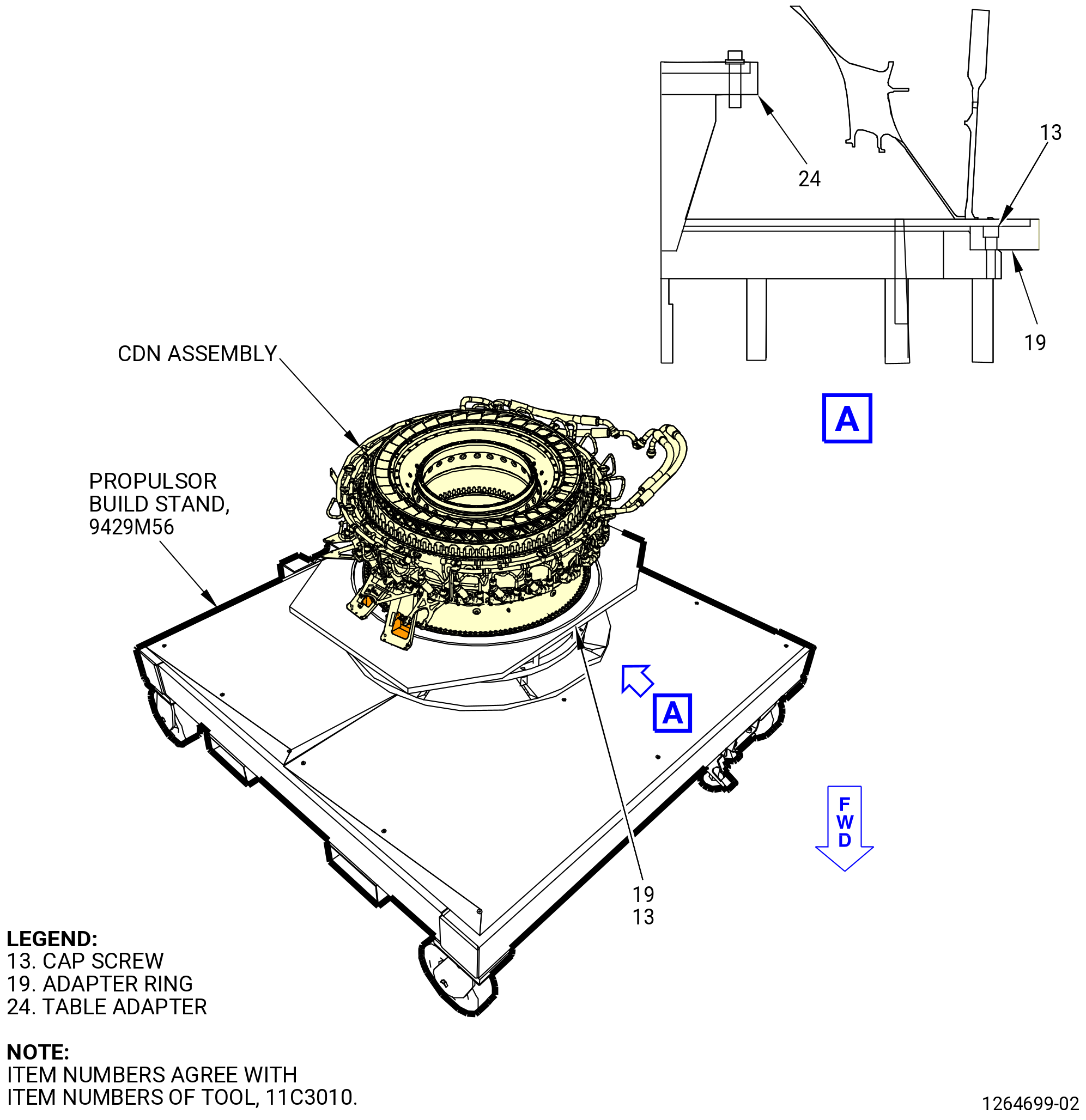
| A. | Make sure that the CDN assembly is correctly installed on the 11C3010 build-up fixture. Refer to Figure 1002. |
| NOTE: |
|
| (1) | If the CDN assembly is not available, use the 11C3051 CDN dummy case and attach the HPT section to the CDN assembly at the end of this procedure. |
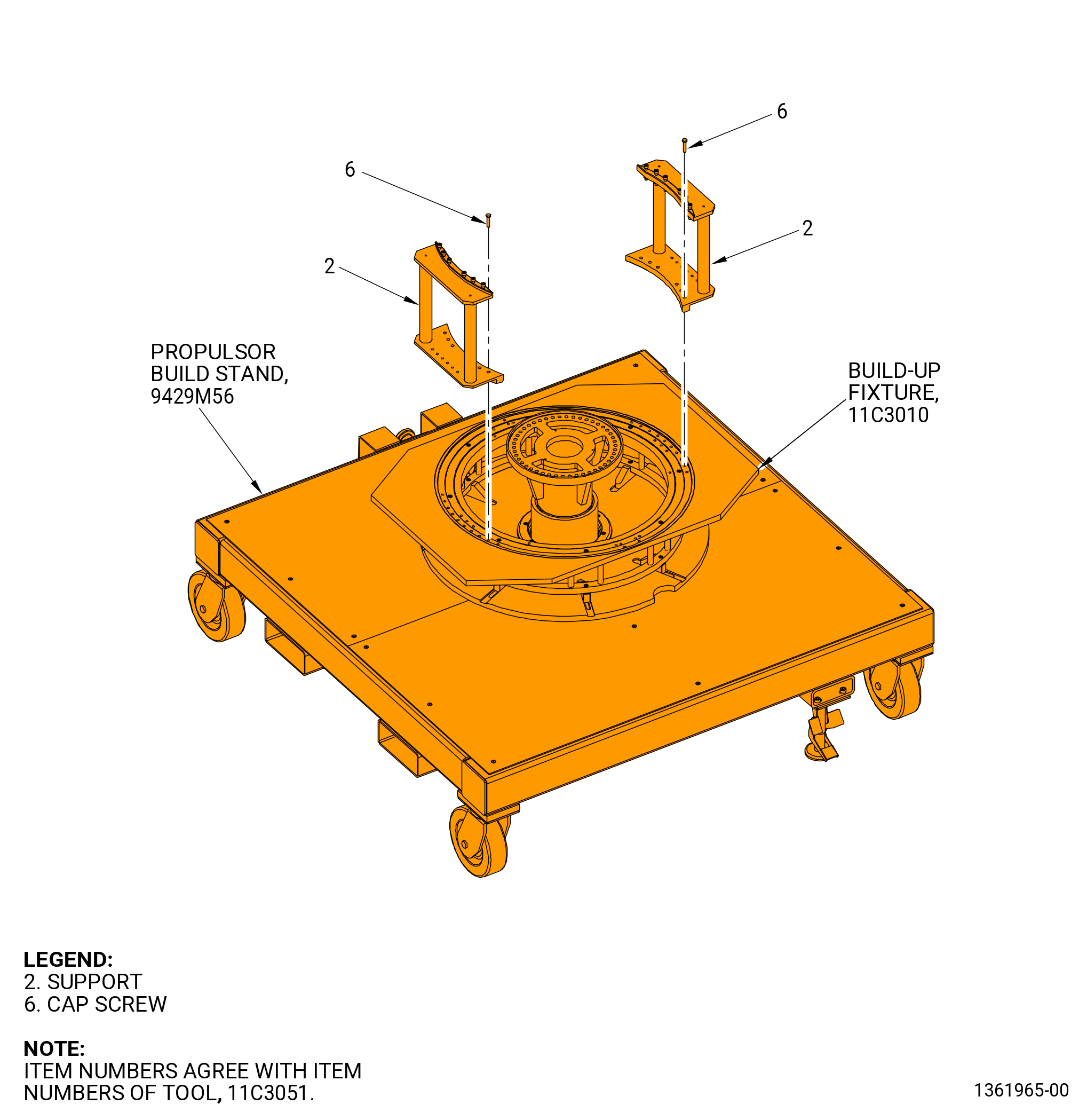
| (a) | Install the 11C3051 CDN dummy case on the 11C3010 build-up fixture as follows. Refer to Figure 1003. |
| 1 | Install one support (item 2) of the 11C3051 CDN dummy case on the 11C3010 build-up fixture with six cap screws (item 6). |
| 2 | Tighten the six cap screws (item 6) until fully seated. |
| 3 | Install the second support (item 2) of the 11C3051 CDN dummy case on the 11C3010 build-up fixture with six cap screws (item 6). |
| 4 | Tighten the six cap screws (item 6) until fully seated. |
| Subtask 72-50-00-430-123 |
| B. | Do not do this procedure if the 11C3051 CDN dummy case is used. Remove the 11C3383 nozzle cover from the combustor diffuser assembly (01-089 , 72-40-00) (SIN 12000) or (01-090 , 72-40-00) (SIN 12000) or (01-091 , 72-40-00) (SIN 12000) or (01-092 , 72-40-00) (SIN 12000). Refer to Figure 1004. |
| Subtask 72-50-00-220-012 |
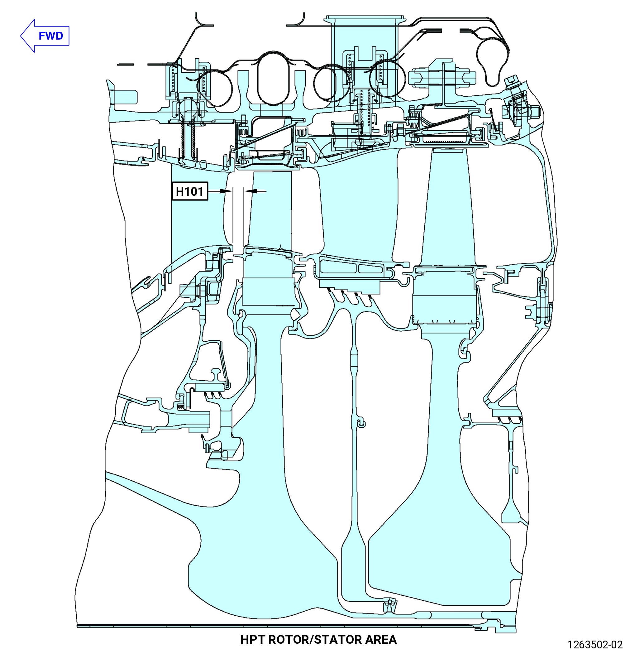
| C. | Calculate and record the clearances between the HPT stage 1 nozzle assembly (01-080 , 72-40-00) (SIN 17200) or (01-081 , 72-40-00) (SIN 17200) or (01-082 , 72-40-00) (SIN 17200) and HPT rotor assembly (34-020 , 72-00-02) (SIN 15000) or (34-021 , 72-00-02) (SIN 15000). Refer to Figure 1005, Figure 1006, and do as follows: |
| NOTE: |
|
| NOTE: |
|
| NOTE: |
|
| (1) | Deleted. |
| (2) | Deleted. |
| (3) | Deleted. |
| (4) | Deleted. |
| NOTE: |
|
| (5) | Deleted. |
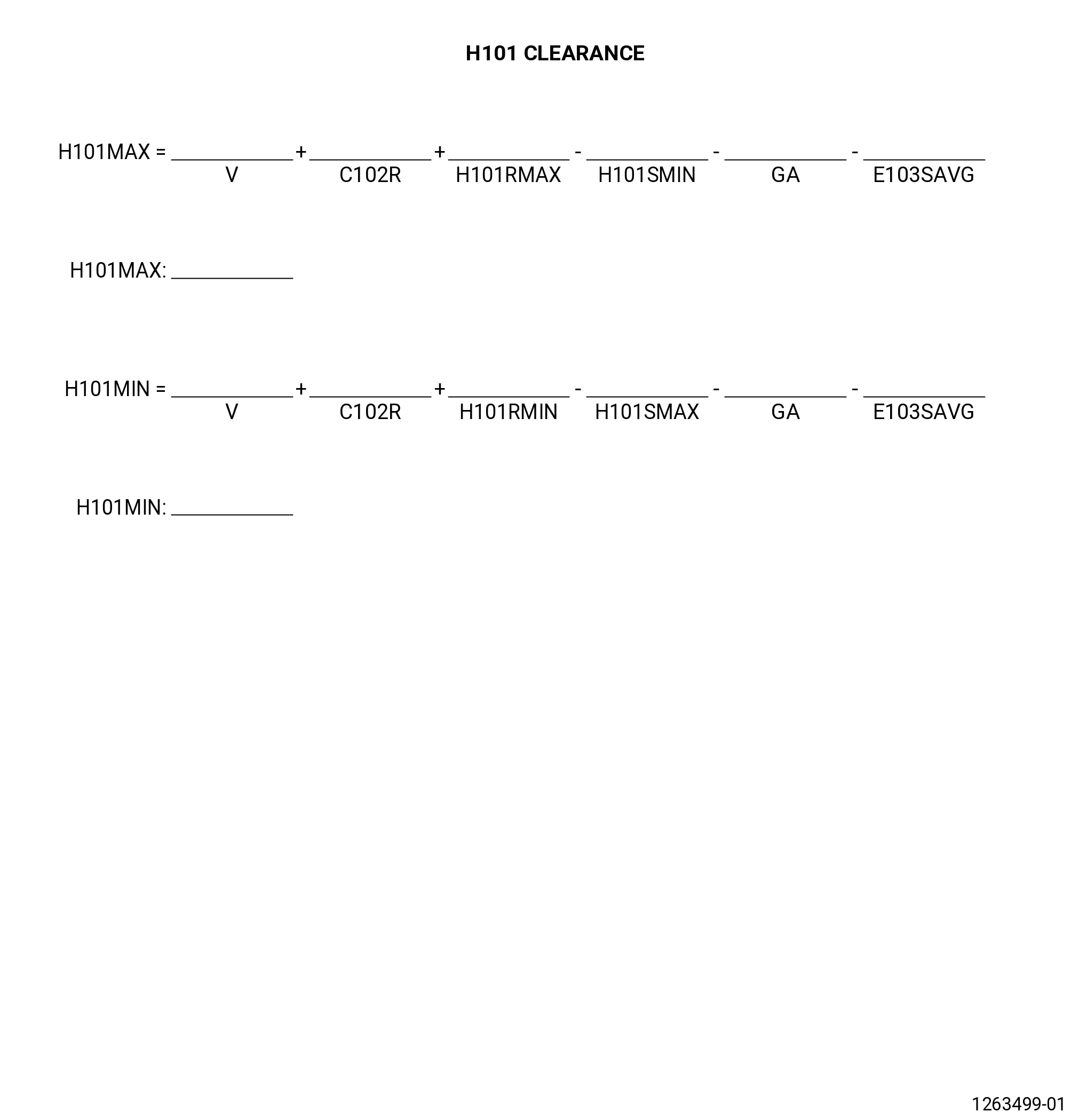
| (6) | To calculate the axial clearance, H101 record the values that follow: |
| (a) | Record the value for dimension V on the record sheet. Refer to TASK 72-30-00-440-801 (72-30-00, ASSEMBLY 001 CONFIG 01) or TASK 72-30-00-440-805 (72-30-00, ASSEMBLY 001 CONFIG 02). |
| (b) | Record the value for dimension C102R on the record sheet. Refer to TASK 72-30-00-440-802 (72-30-00, ASSEMBLY 002 CONFIG 01) or TASK 72-30-00-440-804 (72-30-00, ASSEMBLY 002 CONFIG 02). |
| (c) | Record the value for dimension H101RMIN and H101RMAX on the record sheet. Refer to TASK 72-53-00-440-802 (72-53-00, ASSEMBLY 001 CONFIG 01) or TASK 72-53-00-440-803 (72-53-00, ASSEMBLY 001 CONFIG 02). |
| (d) | Record the value for dimension H101SMIN and H101SMAX on the record sheet. Refer to TASK 72-40-00-440-801 (72-40-00, ASSEMBLY 001 CONFIG 01) or TASK 72-40-00-440-802 (72-40-00, ASSEMBLY 001 CONFIG 02). |
| (e) | Record the value for dimension GA on the record sheet. Refer to TASK 72-30-00-440-802 (72-30-00, ASSEMBLY 002 CONFIG 01) or TASK 72-30-00-440-804 (72-30-00, ASSEMBLY 002 CONFIG 02). |
| (f) | Record the value for dimension E103SAVG on the record sheet. Refer to TASK 72-25-00-440-801 (72-25-00, ASSEMBLY 001). |
| (g) | Calculate H101MIN and H101MAX on the record sheet. |
| NOTE: |
|
| * * * FOR ALL |
| (h) | Make sure that the minimum value for H101MIN is not less than 0.233 inch (5.92 mm). |
| (i) | Make sure that the maximum value for H101MAX is not more than 0.315 inch (8.00 mm). |
| * * * FOR ALL |
| (j) | Make sure that the minimum value for H101MIN is not less than 0.239 inch (6.08 mm). |
| (k) | Make sure that the maximum value for H101MAX is not more than 0.321 inch (8.15 mm). |
| (7) | Deleted. |
| (8) | Deleted. |
| (9) | Deleted. |
| (10) | If a calculated clearance is not in tolerance, find the cause and correct before you continue to build-up the HPT module. |
| Subtask 72-50-00-430-116 |
| D. | Install the HPT rotor assembly (34-020 , 72-00-02) (SIN 15000) or (34-021 , 72-00-02) (SIN 15000) on the aft end of the CDN assembly or the 11C3051 CDN dummy case as follows: |
| Subtask 72-50-00-430-117 |
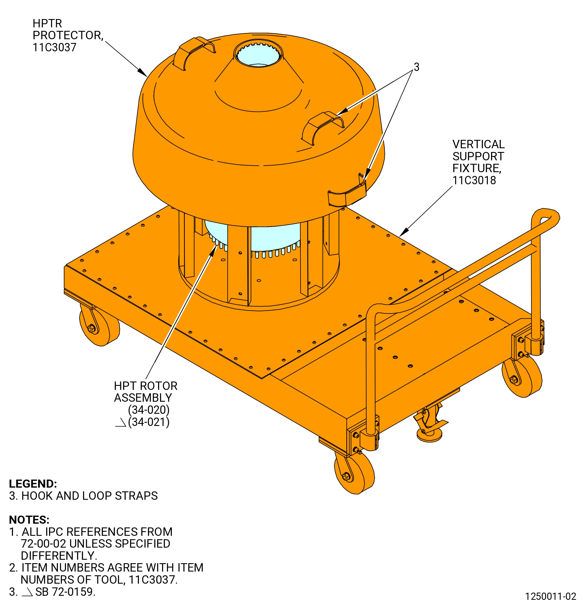
| (1) | Remove the 11C3037 protector from the HPT rotor assembly as follows. Refer to Figure 1007. |
| (a) | Adjust the top and side hook and loop straps (item 3) of the 11C3037 protector until you can get a hold on them. |
| (b) | Use the hook and loop straps (item 3) to lift the 11C3037 protector from the HPT rotor assembly. |
| (2) | Remove the 11C3019 slave blade retainer from the high pressure turbine rotor (HPTR) stage 2 disk (01-130 , 72-53-00) (SIN 150B1) or (02-130 , 72-53-00) (SIN 150B1). Refer to Figure 1008 and do as follows: |
| (a) | Turn the hand knobs (item 10) opposite each other around the circumference to loosen the clamps (item 11). |
| (b) | Move the check nut (item 4) to put the clamps (item 11) in the DISENGAGED position as shown on the retaining ring (item 2). |
| (c) | Thread the slide hammer puller (item 5) into one of the eight threaded holes in the retaining ring (item 2). |
| (d) | Remove the 11C3019 slave blade retainer with the slide hammer puller (item 5). Move the slide hammer puller (item 5) to different locations on the retaining ring (item 2), as necessary, to remove the slave blade retainer. |
| Subtask 72-50-00-430-016 |
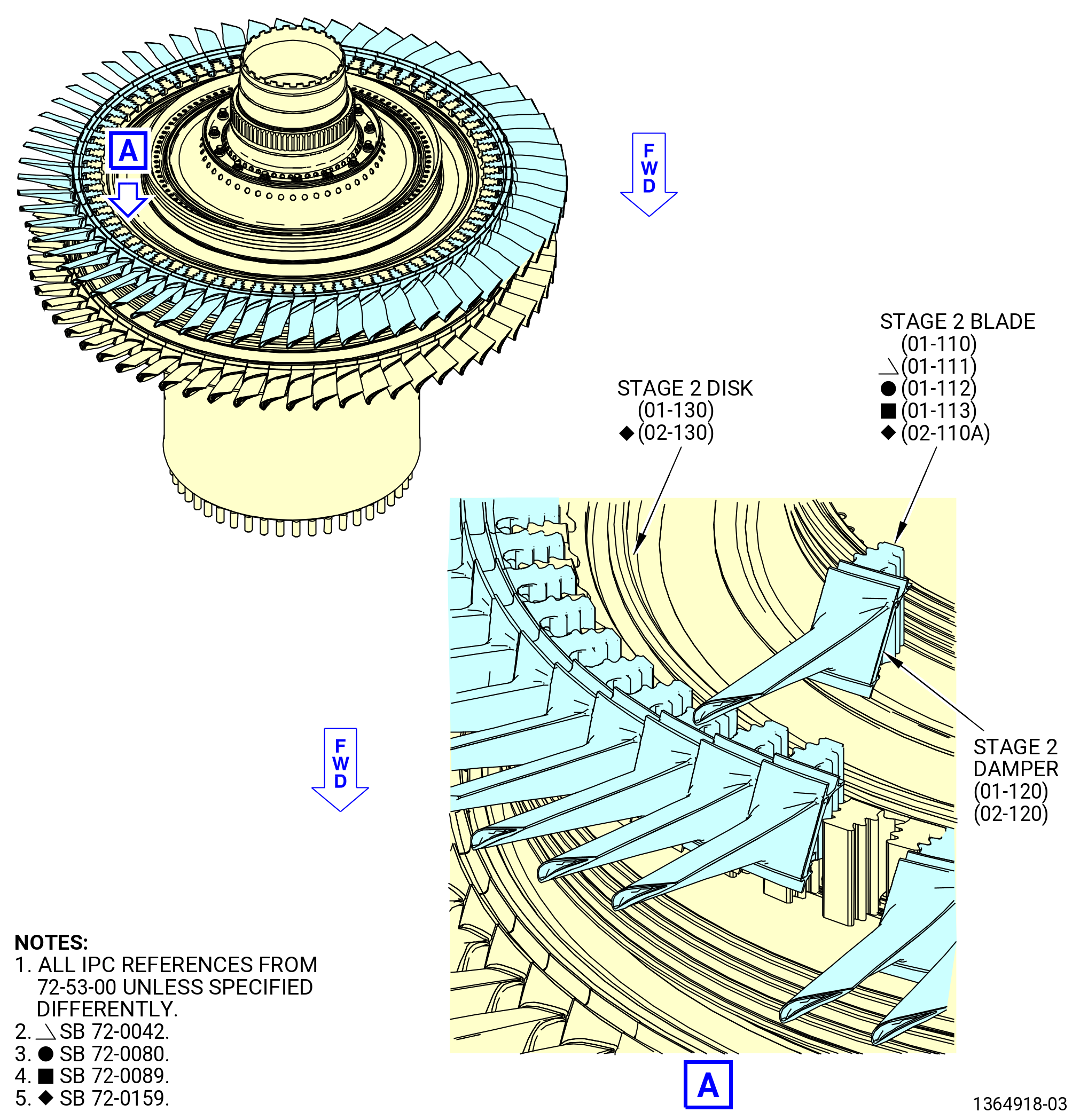
| (3) | Remove the stage 2 HPT rotor blades (stage 2 blades) (01-110 , 72-53-00) (SIN 150B0) or (01-111 , 72-53-00) (SIN 150B0) or (01-112 , 72-53-00) (SIN 150B0) or (01-113 , 72-53-00) (SIN 150B0) or (02-110A , 72-53-00) (SIN 150B0) with the stage 2 HPT rotor blade dampers (stage 2 dampers) (01-120 , 72-53-00) (SIN 150B8) or (02-120 , 72-53-00) (SIN 150B8) from the HPTR stage 2 disk (01-130 , 72-53-00) (SIN 150B1) or (02-130 , 72-53-00) (SIN 150B1). Refer to Figure 1009 and do as follows: |
| (a) | Make sure that you can read the number marks on the stage 2 blades related to their positions in the HPTR stage 2 disk. If not, use the C05-003 pen to put marks on the stage 2 blades related to their positions in the HPTR stage 2 disk. Start the marks with the 1-1 slot in the HPTR stage 2 disk and move CW, ALF. |
| (b) | To remove the first stage 2 blade, move (fan out) approximately 15 blades aft in the HPTR stage 2 disk dovetail slot a small distance until you can remove the first blade. |
| (c) | Continue to remove the stage 2 blades and stage 2 dampers from the HPTR stage 2 disk. Make sure that you do not disengage the stage 2 dampers from the stage 2 blades. |
| (d) | Put all the stage 2 blades in the 11C3015 blade container, airfoils facing down. |
| Subtask 72-50-00-430-114 |
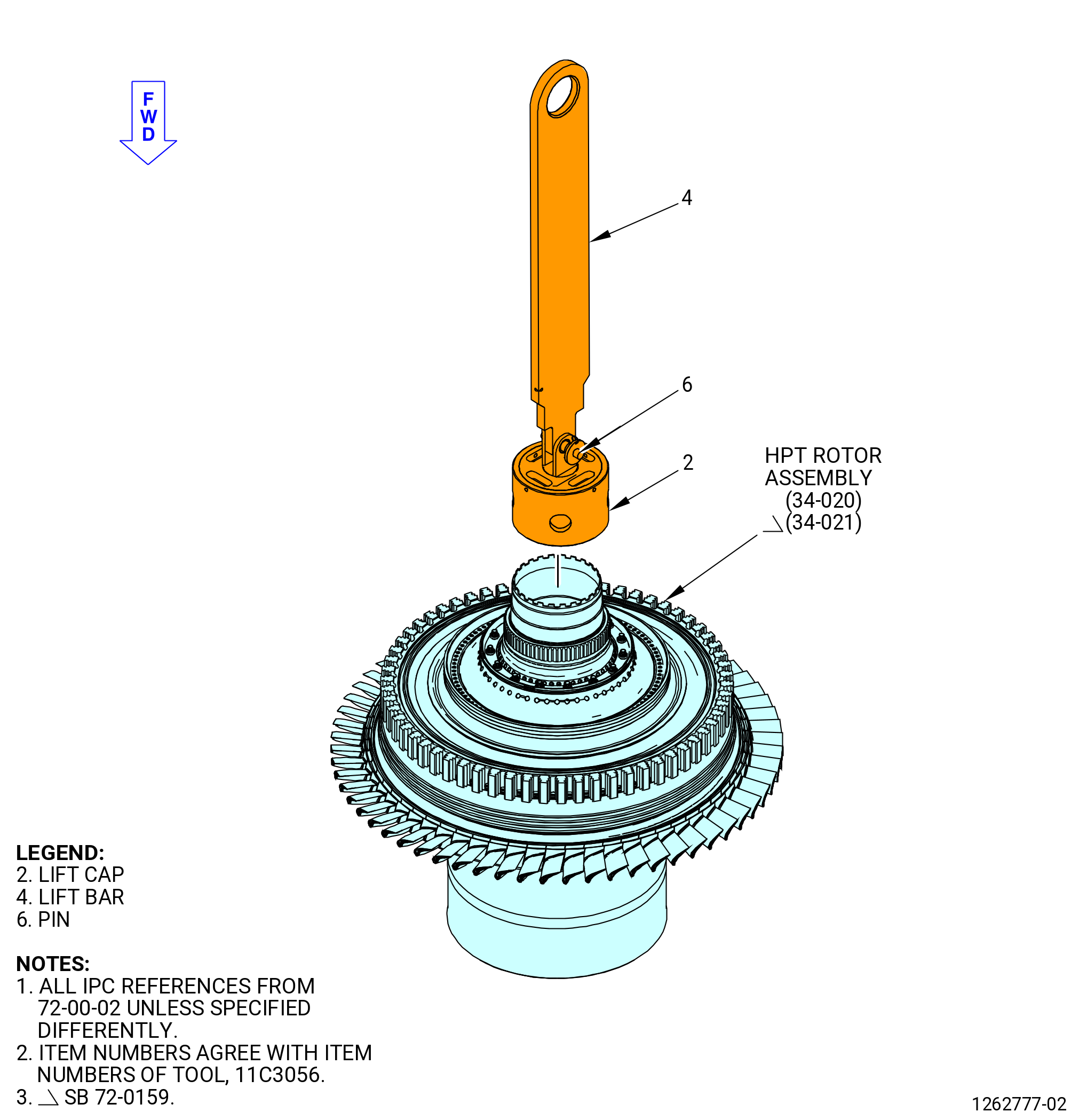
| (4) | Attach the 11C3056 lift/turn fixture to the HPT rotor assembly as follows. Refer to Figure 1010. |
| CAUTION: |
|
| (a) | Thread the lift cap (item 2) of the 11C3056 lift/turn fixture on the aft end of the HPT rotor assembly until the threads are fully engaged. Do not use force to tighten the lift cap. |
| (b) | Connect the lift bar (item 4) of the 11C3056 lift/turn fixture to the lift cap (item 2) in the vertical position with the pin (item 6). |
| Subtask 72-50-00-430-112 |
| (5) | Attach the lift bar (item 4) of the 11C3056 lift/turn fixture to an overhead hoist. |
| WARNING: |
|
| (6) | Lift the HPT rotor assembly with the 11C3056 lift/turn fixture. |
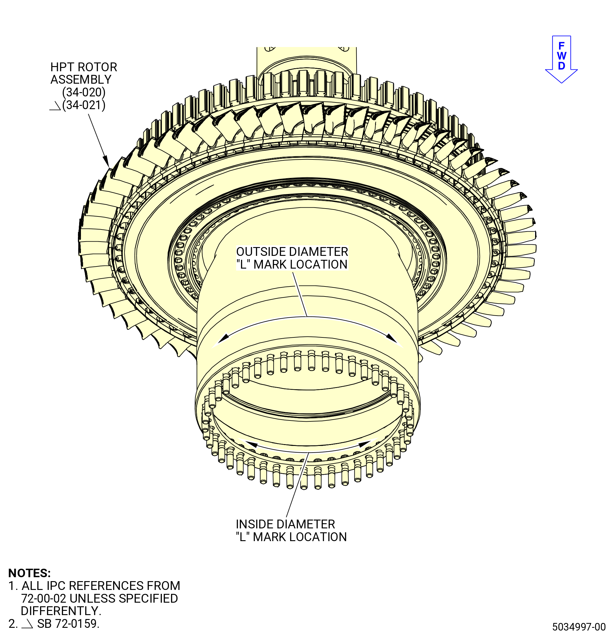
| (7) | Find the L mark on the HPT rotor assembly outside diameter. Transfer the L mark to the inside diameter of the HPT rotor assembly. Use the C05-003 pen to put the L mark at the same circumferential location on the inside diameter of the HPT rotor assembly. Refer to Figure 1011. |
| NOTE: |
|
| Subtask 72-50-00-430-113 |
| (8) | Put the HPT rotor assembly in the CDN assembly or the 11C3051 CDN dummy case, and on the build-up fixture as follows: |
| (a) | Align the L mark on the HPT rotor with TVCL of the 11C3010 build-up fixture. |
| (b) | Slowly lower the HPT rotor assembly into the CDN assembly or the 11C3051 CDN dummy case. Make sure that the L mark on the HPT rotor assembly is aligned with the TVCL of the 11C3010 build-up fixture. |
| (c) | Remove the 11C3056 lift/turn fixture from the HPT rotor assembly. |
| Subtask 72-50-00-430-090 |
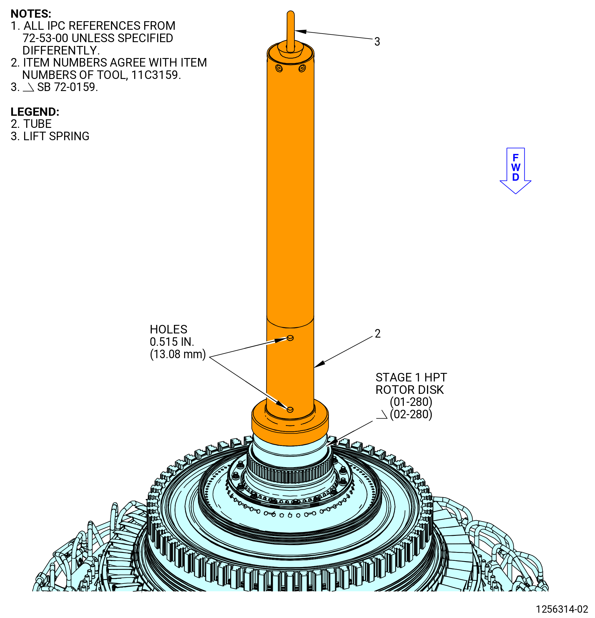
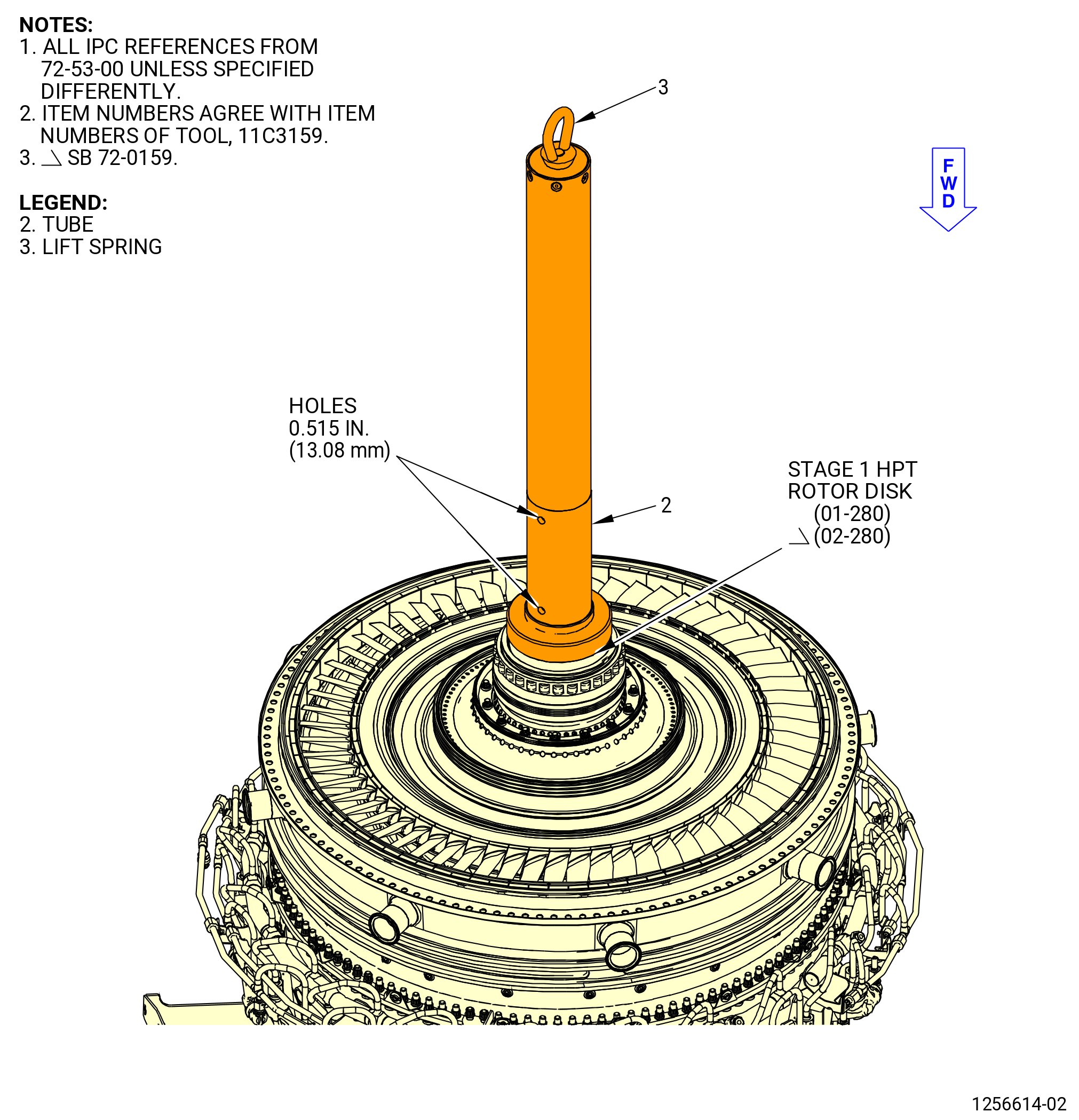
| E. | Attach the 11C3159 guide to the stage 1 HPT rotor disk (01-280 , 72-53-00) (SIN 150A1) or (02-280 , 72-53-00) (SIN 150A1) installed in the CDN assembly or the 11C3051 CDN dummy case. Refer to Figure 1012 and do as follows: |
| (1) | Attach an overhead hoist to the eye of the lift spring (item 3). |
| WARNING: |
|
| (2) | Lift the guide fixture and put the tube (item 2) over the aft end of the stage 1 HPT rotor disk. |
| (3) | Thread the flanged end of the tube (item 2) on the aft end of the stage 1 HPT rotor disk. |
| (4) | Put the breaker bar through the 0.515 inch (13.08 mm) diameter holes of the tube (item 2). |
| CAUTION: |
|
| (5) | Use the bar to turn the tube (item 2) on the stage 1 HPT rotor disk. Do not use excessive force to install the tube. |
| (6) | Remove the breaker bar from the tube (item 2). |
| Subtask 72-50-00-430-091 |
| F. | Install the HPT stage 2 nozzle assembly (34-010 , 72-00-02) (SIN 17400) or (34-011 , 72-00-02) (SIN 17400) or (34-012 , 72-00-02) (SIN 17400) on the CDN assembly or the 11C3051 CDN dummy case as follows: |
| NOTE: |
|
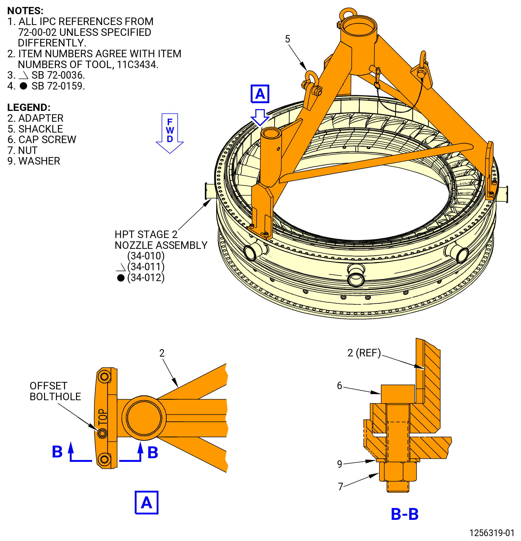
| (1) | Attach the 11C3434 lift/turn fixture on the aft end of the HPT stage 2 nozzle assembly (34-010 , 72-00-02) (SIN 17400) or (34-011 , 72-00-02) (SIN 17400) or (34-012 , 72-00-02) (SIN 17400). Refer to Figure 1013 and do as follows: |
| (a) | Attach an overhead hoist to a three-legged sling. |
| (b) | Attach the three-legged sling to the three shackles (item 5). |
| WARNING: |
|
| (c) | Lift the 11C3434 lift/turn fixture and align the foot of the adapter (item 2) marked as TOP with the TVCL of the HPT stage 2 nozzle assembly. |
| (d) | Align the offset bolthole at TVCL in the aft flange of the HPT stage 2 nozzle assemlby with the offset bolthole in the adapter (item 2) marked as TOP. |
| (e) | Lower the 11C3434 lift/turn fixture to the aft flange of the HPT stage 2 nozzle assembly. |
| (f) | Attach the 11C3434 lift/turn fixture to the aft flange of the HPT stage 2 nozzle assembly with the cap screws (item 6), washers (item 9), and nuts (item 7). Put the cap screw heads on the aft side of the flange and the washers and nuts on the forward side of the flange. Tighten the nuts (item 7) with a wrench. |
| (g) | If necessary, remove the slave HPT stage 2 nozzle hardware. |
| Subtask 72-50-00-430-118 |
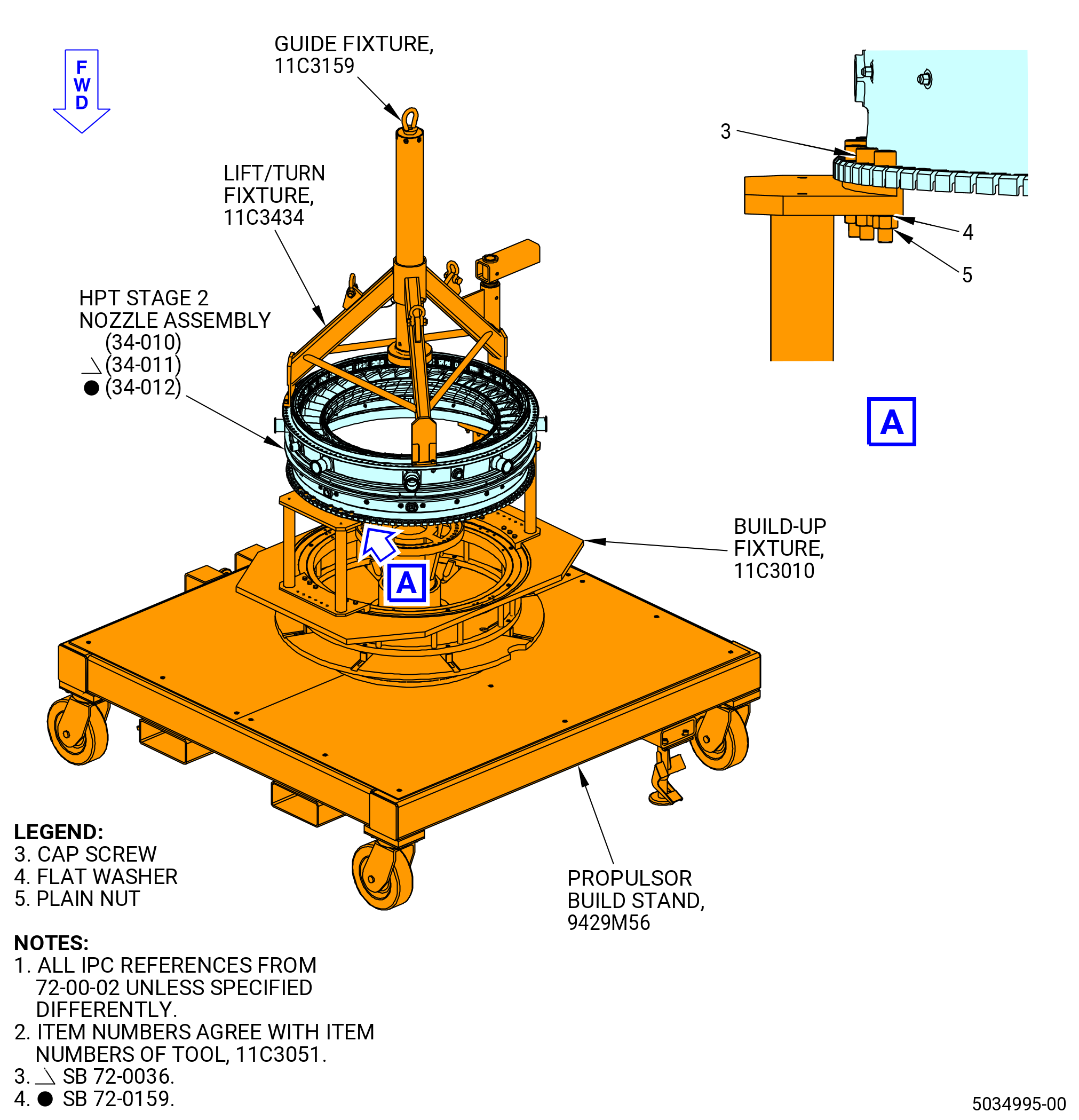
| (2) | Alternative Procedure Available. Install the HPT stage 2 nozzle assembly on the CDN assembly. Refer to Figure 1014 and do as follows: |
| (a) | Make sure that the HPT stage 2 nozzle assembly borescope hole is aligned with the hole in the case. |
| WARNING: |
|
| (b) | Lift the HPT stage 2 nozzle assembly with an overhead hoist and put it over the CDN assembly. |
| (c) | Carefully lower the HPT stage 2 nozzle assembly and engage the 11C3159 guide with the adapter (item 2) of the 11C3434 lift/turn fixture. |
| (d) | Align the TVCL and offset boltholes of the HPT stage 2 nozzle assembly to the TVCL and offset boltholes of the CDN assembly. |
| (e) | Lower the HPT stage 2 nozzle assembly on the CDN assembly. Engage the bolts (12024) in the CDN assembly aft flange through the boltholes in the HPT stage 2 nozzle assembly. Make sure that the offset boltholes are aligned. |
| Subtask 72-50-00-430-125 |
| (2).A. | Alternative Procedure. Install the HPT stage 2 nozzle assembly (34-010 , 72-00-02) (SIN 17400) or (34-011 , 72-00-02) (SIN 17400) or (34-012 , 72-00-02) (SIN 17400) on the 11C3051 CDN dummy case. Refer to Figure 1014 and do as follows: |
| WARNING: |
|
| (a) | Lift the HPT stage 2 nozzle assembly with an overhead hoist and put it over the 11C3051 CDN dummy case. |
| (b) | Carefully lower the HPT stage 2 nozzle assembly and engage the 11C3159 guide with the adapter (item 2) of the 11C3434 lift/turn fixture. |
| (c) | Align the TVCL and offset boltholes of the HPT stage 2 nozzle assembly with the TVCL and offset boltholes of the 11C3051 CDN dummy case. |
| (d) | Lower the HPT stage 2 nozzle assembly onto the 11C3051 CDN dummy case. |
| (e) | Use 12 cap screws (item 3), flat washers (item 4), and plain nuts (item 5) to attach HPT stage 2 nozzle assembly forward flange with the 11C3051 CDN dummy case aft flange. |
| (f) | Tighten the nuts until HPT assembly is fully seated. Make sure the offset boltholes are aligned. |
| Subtask 72-50-00-430-126 |
| (3) | Remove the 11C3434 lift/turn fixture from the HPT stage 2 nozzle assembly. |
| (4) | Remove the 11C3159 guide from the stage 1 HPT rotor disk (01-280 , 72-53-00) (SIN 150A1) or (02-280 , 72-53-00) (SIN 150A1). |
| (5) | Make sure that the 11C3140 protector is installed on the HPT stage 2 nozzle assembly to protect the stage 2 nozzles from damage. Refer to Figure 1015. |
| Subtask 72-50-00-430-092 |
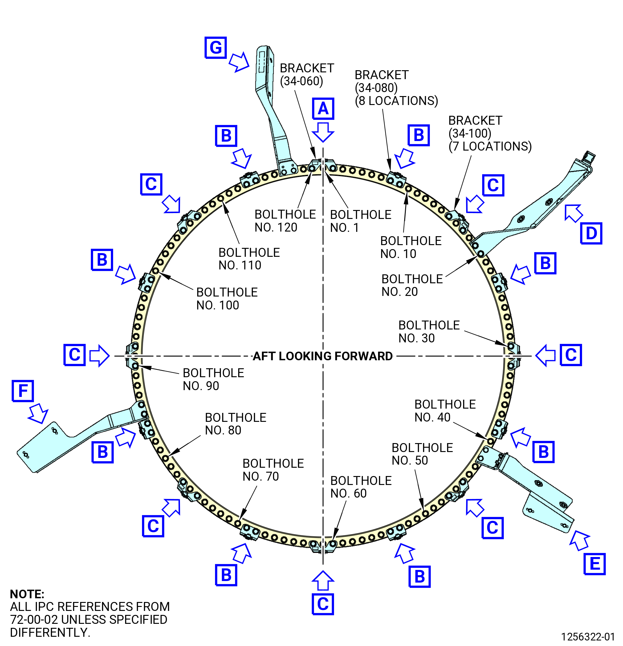
| G. | Do not do this procedure if the 11C3051 CDN dummy case is used. Install the bridge plates and brackets on the HPT stage 2 nozzle assembly (34-010 , 72-00-02) (SIN 17400) or (34-011 , 72-00-02) (SIN 17400) or (34-012 , 72-00-02) (SIN 17400) and CDN assembly flanges. Refer to Figure 1016, Figure 1017, and do as follows: |
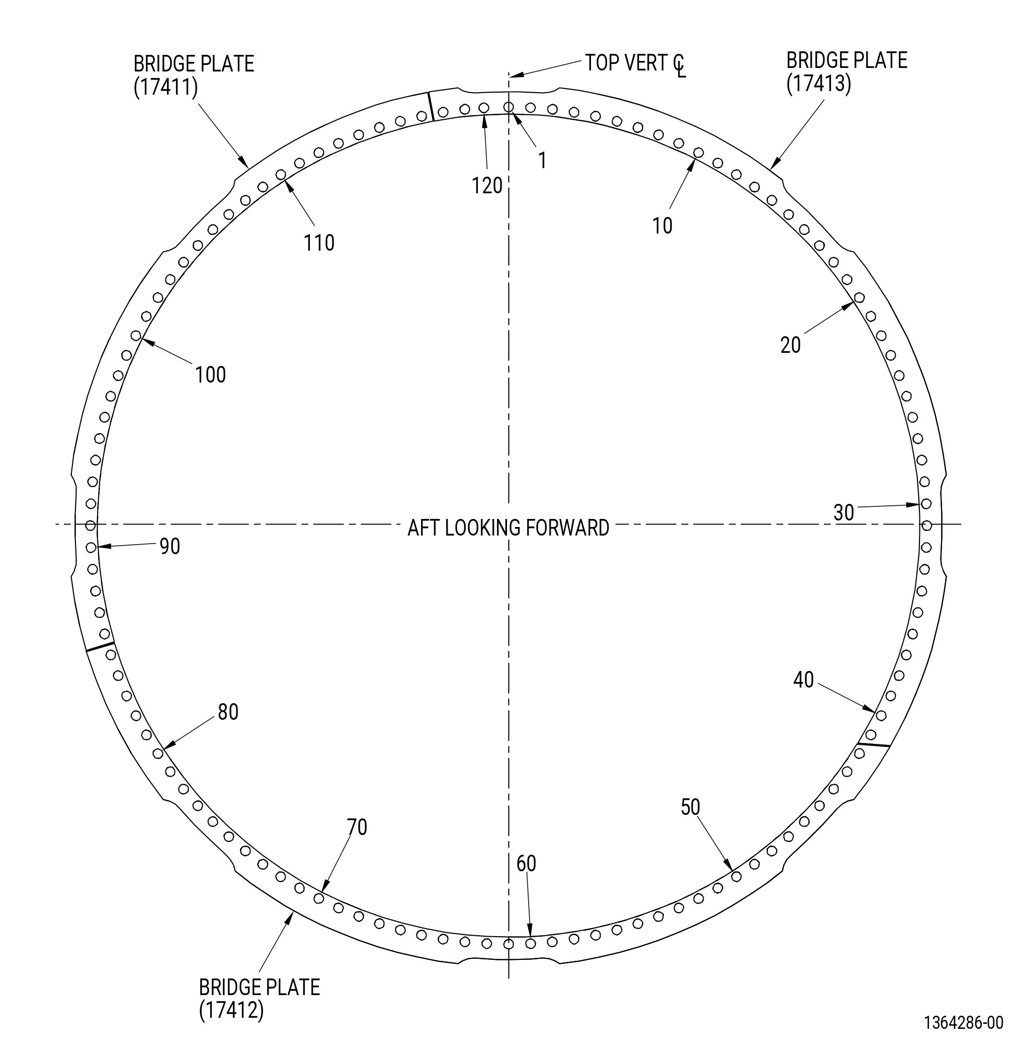
| (1) | Start at bolthole No. 1 TVCL and in a CW direction ALF, number every ten bolthole with a C05-003 pen . |
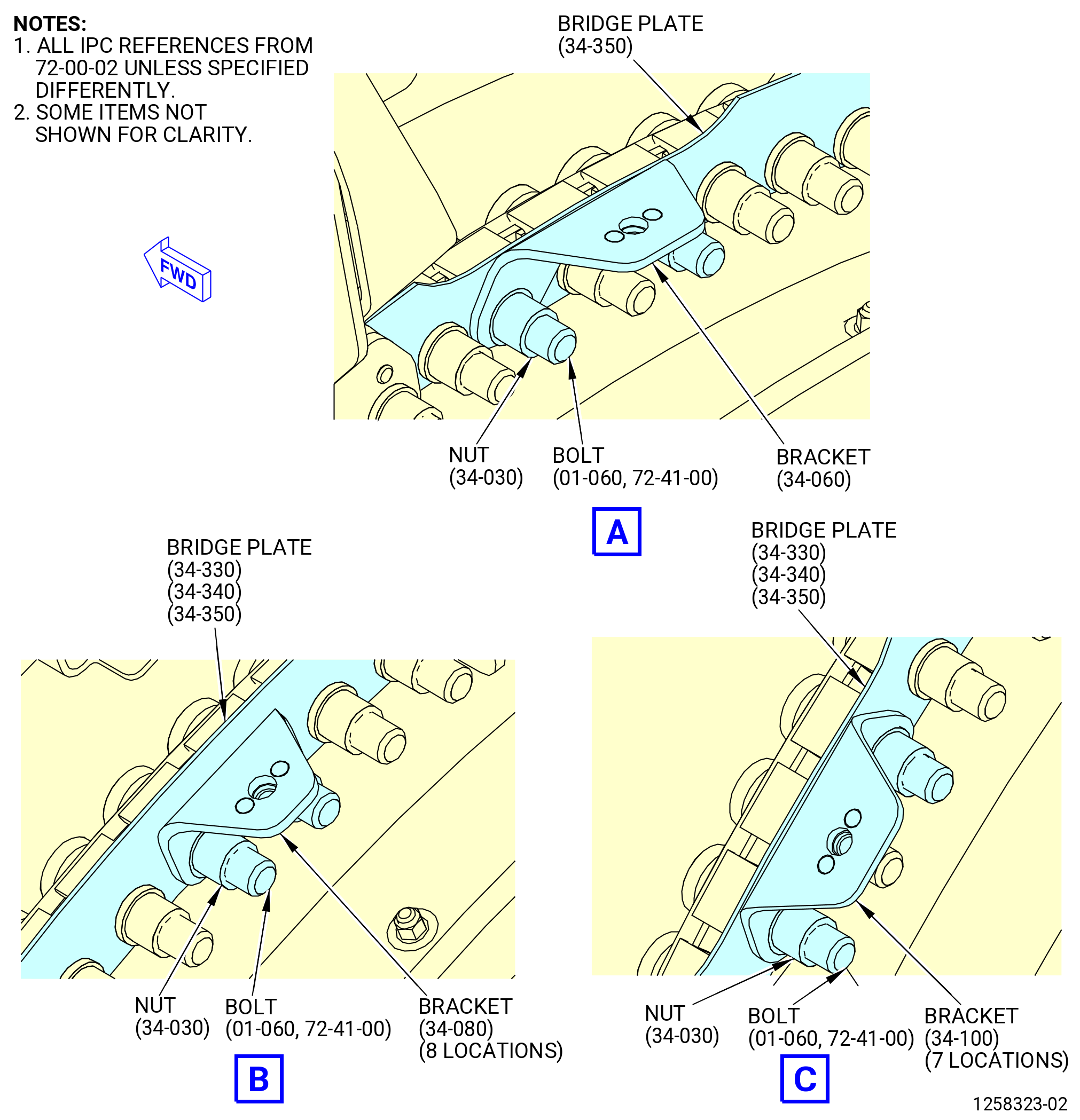
| (2) | Install bridge plate (34-350 , 72-00-02) (SIN 17413) from bolts 118 to 41. |
| (3) | Install bridge plate (34-340 , 72-00-02) (SIN 17412) from bolts 42 to 85. |
| (4) | Install bridge plate (34-330 , 72-00-02) (SIN 17411) from bolts 86 to 117. |
| (5) | Apply C02-058 lubricant to the threads and friction surfaces of the nuts (17440). |
| (6) | Install the 16 nuts (17440) in the boltholes No. 4-5,13-14, 34-35, 50-51, 64-65, 80-81, 94-95, and 110-111. Torque the nuts in a criss-cross pattern to 276-324 lb in. (31.2-36.6 N.m). |
| Subtask 72-50-00-430-128 |
| * * * PRE SB 75-0003( HPTACC without Brackets Reduction ) |
| (7) | Install the 64 nuts (34-030 , 72-00-02) (SIN 17440) in the boltholes No. 1, 3, 6-7, 10-12, 16, 18, 21-22, 25, 29, 31, 33, 36-37, 40, 43-44, 46, 48-49, 52, 55-59, 61, 63, 66-67, 70-74, 76, 78-79, 82, 87-89, 91, 93, 96-97, 100-104, 106, 108-109, 112, 115-116, and 119. |
| * * * END PRE SB 75-0003( ) |
| Subtask 72-50-00-430-129 |
| * * * SB 75-0003( HPTACC with Brackets Reduction ) |
| (7).A. | Install the 64 nuts (34-030 , 72-00-02) (SIN 17440) in the boltholes No. 1, 3, 6-7, 10-12, 17-18, 21-23, 29, 32-33, 36-37, 40, 43-44, 46, 48-49, 52, 55-59, 61, 63, 66-67, 70-74, 76, 78-79, 82, 87-89, 91, 93, 96-97, 100-104, 106, 108-109, 112, 115-116, and 119. |
| * * * END SB 75-0003( ) |
| Subtask 72-50-00-430-130 |
| (8) | Torque the all the 80 nuts in a criss-cross pattern to 368-432 lb in. (41.6-48.8 N.m) |
| (9) | Install the brackets on the aft side of CDN assembly and HPT stage 2 nozzle assembly flanges as follows: |
| Subtask 72-50-00-430-131 |
| * * * PRE SB 75-0003( HPTACC without Brackets Reduction ) |
| (a) | Install the bracket (34-060 , 72-00-02) (SIN 62119) at the boltholes No. 2 and 120 with the nuts (34-030 , 72-00-02) (SIN 17440). Hand-tighten the nuts. |
| * * * END PRE SB 75-0003( ) |
| Subtask 72-50-00-430-132 |
| * * * SB 75-0003( HPTACC with Brackets Reduction ) |
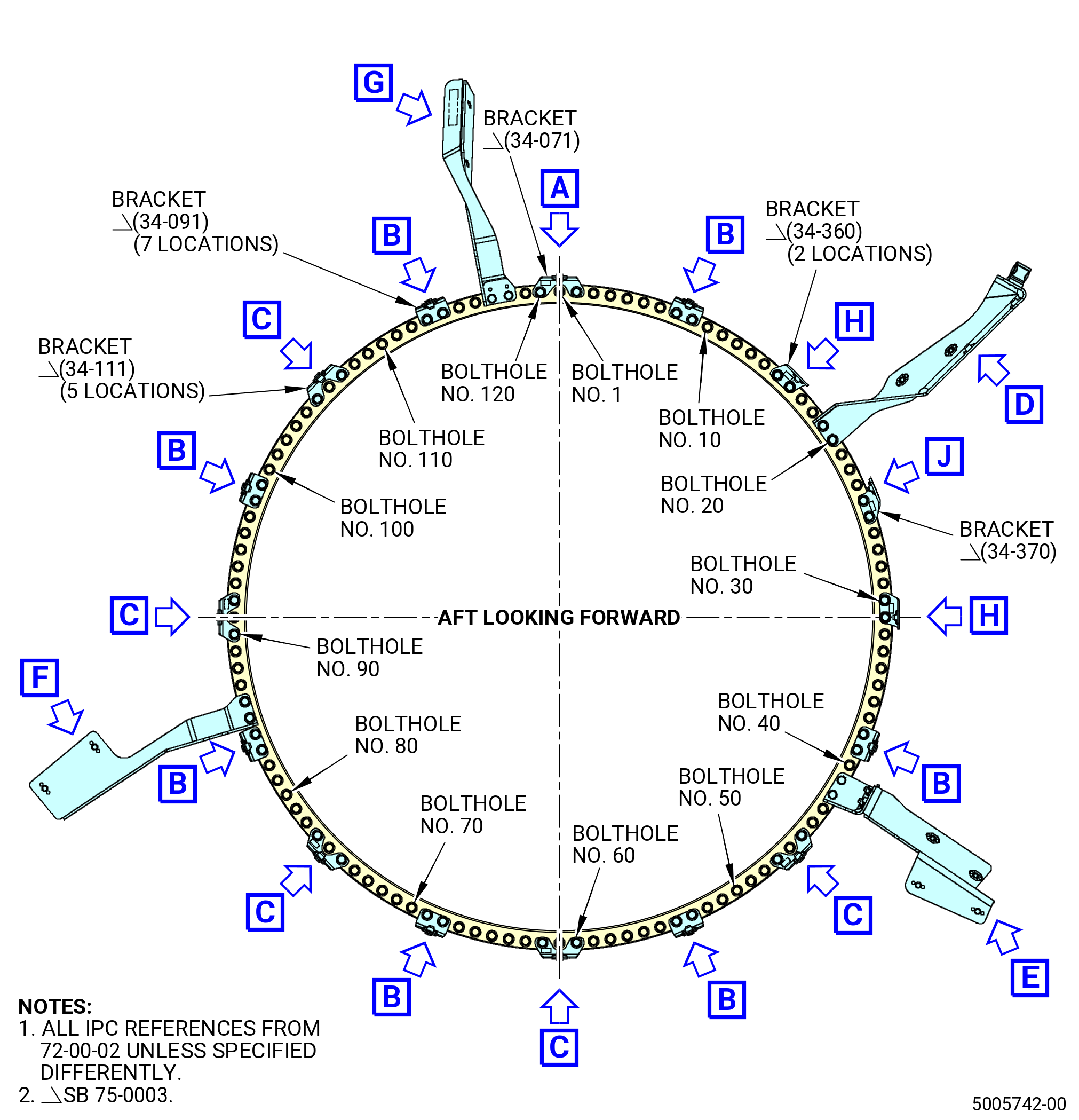
| (a).A. | Install the bracket (34-071 , 72-00-02) (SIN 62119) at the boltholes No. 2 and 120 with the nuts (34-030 , 72-00-02) (SIN 17440). Hand-tighten the nuts. |
| * * * END SB 75-0003( ) |
| Subtask 72-50-00-430-133 |
| * * * PRE SB 75-0003( HPTACC without Brackets Reduction ) |
| (b) | Install the eight brackets (34-080 , 72-00-02) (SIN 6211B) at the boltholes No. 8-9, 23-24, 38-39, 53-54, 68-69, 83-84, 98-99, 113-114 with the nuts (34-030 , 72-00-02) (SIN 17440). Hand-tighten the nuts. |
| * * * END PRE SB 75-0003( ) |
| Subtask 72-50-00-430-134 |
| * * * SB 75-0003( HPTACC with Brackets Reduction ) |
| (b).A. | Install the seven brackets (34-091 , 72-00-02) (SIN 6211B) at the boltholes No. 8-9, 38-39, 53-54, 68-69, 83-84, 98-99, and 113-114 with the nuts (34-030 , 72-00-02) (SIN 17440). Hand-tighten the nuts. |
| * * * END SB 75-0003( ) |
| Subtask 72-50-00-430-135 |
| * * * PRE SB 75-0003( HPTACC without Brackets Reduction ) |
| (c) | Install the seven brackets (34-100 , 72-00-02) (SIN 6211A) at the boltholes No. 15 and 17, 30 and 32, 45 and 47, 60 and 62, 75 and 77, 90 and 92, 105 and 107 with the nuts (34-030 , 72-00-02) (SIN 17440). Hand-tighten the nuts. |
| * * * END PRE SB 75-0003( ) |
| Subtask 72-50-00-430-136 |
| * * * SB 75-0003( HPTACC with Brackets Reduction ) |
| (c).A. | Install the five brackets (34-111 , 72-00-02) (SIN 6211A) at the boltholes No. 45 and 47, 60 and 62, 75 and 77, 90 and 92, 105 and 107 with the nuts (34-030 , 72-00-02) (SIN 17440). Hand-tighten the nuts. |
| * * * END SB 75-0003( ) |
| Subtask 72-50-00-430-137 |
| * * * SB 75-0003( HPTACC with Brackets Reduction ) |
| (d) | Install the HPT manifold brackets (bracket) (34-360 , 72-00-02) (SIN 6211D) at the boltholes No. 15-16 and 30-31 with the nuts (34-030 , 72-00-02) (SIN 17440). Hand-tighten the nuts. |
| NOTE: |
|
| * * * END SB 75-0003( ) |
| Subtask 72-50-00-430-138 |
| * * * SB 75-0003( HPTACC with Brackets Reduction ) |
| (e) | Install the HPT manifold bracket (bracket) (34-370 , 72-00-02) (SIN 6211E) at the boltholes No. 24-25 with the nuts (34-030 , 72-00-02) (SIN 17440). Hand-tighten the nuts. |
| NOTE: |
|
| * * * END SB 75-0003( ) |
| Subtask 72-50-00-430-139 |
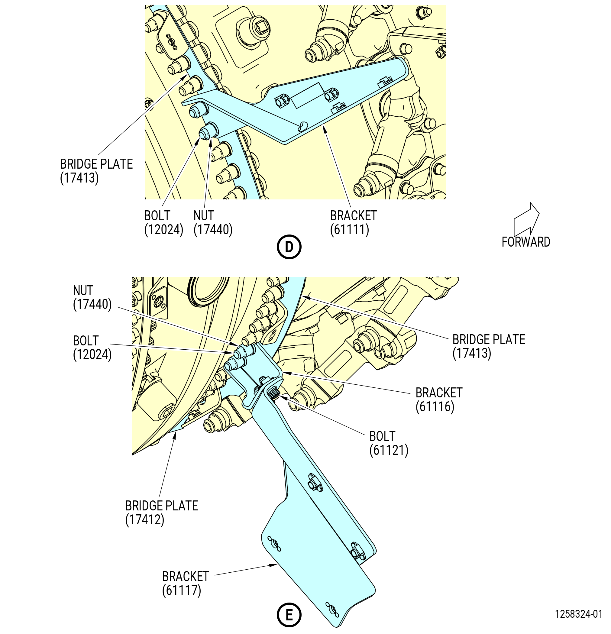
| (f) | Install the 7th stage air support bracket (bracket) (61111) at the boltholes No. 19-20 with the nuts (17440). Tighten the nuts (17440) hand tight. |
| (g) | Install the 7th stage air damper bracket (bracket) (61116) at the boltholes No. 41-42 with the nuts (17440). Tighten the nuts hand tight. |
| (h) | Attach the support bracket (bracket) (61117) to the 7th stage air damper bracket (61116) with the bolts (61121). Torque the bolts to 106-124 lb in. (12.0-14.0 N.m). |
| (i) | Install the 7th stage air support bracket (bracket) (6111C) at the boltholes No. 85-86 with the nuts (17440). Tighten the nuts hand tight. |
| (j) | Install the 7th stage air support bracket (bracket) (6121N) at the boltholes No. 117-118 with the nuts (17440). Tighten the nuts hand tight. |
| (k) | Make sure that there is no gap between the flanges. Use a 0.001 inch (0.03 mm) gauge to check the gap between the flanges. |
| (l) | Torque all the 40 nuts (17440) in a criss-cross pattern to 368-432 lb in. (41.6-48.8 N.m). |
| (10) | Do the final torque to all the 120 nuts (17440) in a circle pattern to 368-432 lb in. (41.6-48.8 N.m). |
| (11) | Remove the flange markings from the HPT stage 2 nozzle assembly (34-010 , 72-00-02) (SIN 17400) or (34-011 , 72-00-02) (SIN 17400) or (34-012 , 72-00-02) (SIN 17400). |
|
|
|
|
| Subtask 72-50-00-430-093 |
| H. | Install the stage 2 blades (01-110 , 72-53-00) (SIN 150B0) or (01-111 , 72-53-00) (SIN 150B0) or (01-112 , 72-53-00) (SIN 150B0) or (01-113 , 72-53-00) (SIN 150B0) or (02-110A , 72-53-00) (SIN 150B0) in the HPT stage 2 nozzle assembly (34-010 , 72-00-02) (SIN 17400) or (34-011 , 72-00-02) (SIN 17400) or (34-012 , 72-00-02) (SIN 17400). Refer to Figure 1018 and do as follows: |
| NOTE: |
|
| (1) | Make sure that a stage 2 blade damper (01-120 , 72-53-00) (SIN 150B8) or (02-120 , 72-53-00) (SIN 150B8) is installed in each stage 2 blade. If necessary, install one stage 2 blade damper in the stage 2 blade as follows: |
| (a) | Apply C10-154 beeswax in the stage 2 blade where the stage 2 blade damper) will be installed. |
| (b) | Put the stage 2 blade damper into the stage 2 blade. |
| (2) | Install the stage 2 blades in the stage 2 HPT rotor disk (stage 2 disk) (01-130 , 72-53-00) (SIN 150B1) or (02-130 , 72-53-00) (SIN 150B1) of the HPT stage 2 nozzle assembly as follows: |
| NOTE: |
|
| (a) | Remove the 11C3140 stage 2 protector to install the stage 2 blades. |
| (b) | Install the stage 2 blade marked with the No. 1 in the 1-1 slot of the HPTR stage 2 disk. Be careful to make sure that the stage 2 blade dampers remain correctly installed. |
| (c) | Continue to install the stage 2 blades in a CW direction ALF in the sequence marked on the blades. |
| (d) | To install the last stage 2 blade, move (fan out) approximately 15 blades aft in the dovetail slot a small distance until you can install the last blade. |
| (e) | Push all the stage 2 blades back into position. |
| Subtask 72-50-00-210-005 |
| (3) | Do a visual inspection of the stage 2 blades for correct installation of the stage 2 blade damper (01-120 , 72-53-00) (SIN 150B8) or (02-120 , 72-53-00) (SIN 150B8) as follows: |
| (a) | Move the stage 2 blades apart and use a light source to view the stage 2 blade damper. |
| (b) | Make sure that the stage 2 blade damper is correctly installed in the slot of the stage 2 blade. If not, remove the stage 2 blade and correct as necessary. Replace the stage 2 blade damper if damaged. |
| Subtask 72-50-00-430-095 |
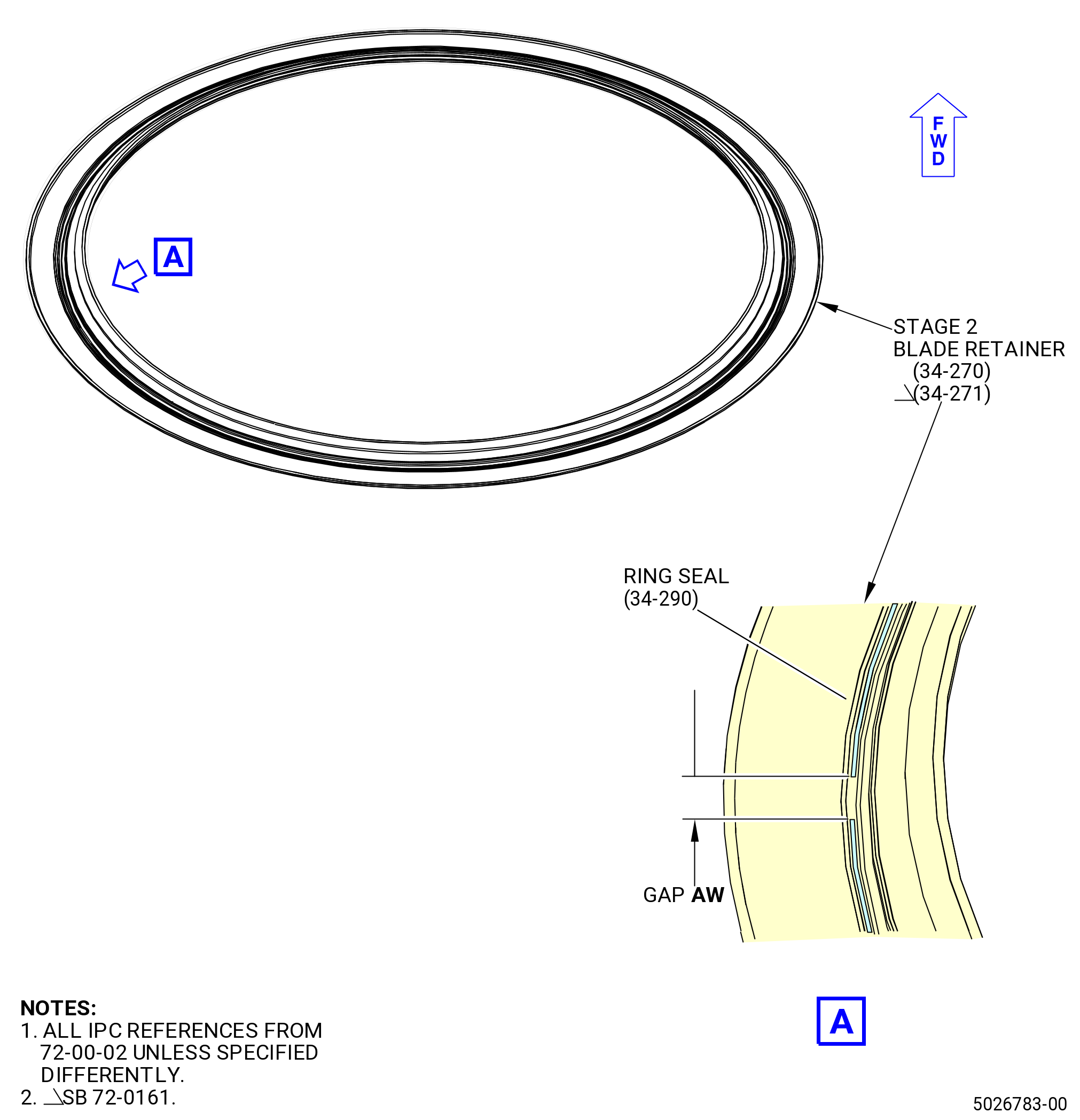
| I. | Install the HPT rotor stage 2 blade retainer (stage 2 blade retainer) (34-270 , 72-00-02) (SIN 150B5) or (34-271 , 72-00-02) (SIN 150B5) and the ring seal (34-290 , 72-00-02) (SIN 150N4) as follows: |
| Subtask 72-50-00-430-096 |
| (1) | Install the ring seal in the groove of the stage 2 blade retainer as follows. Refer to Figure 1019. |
| (a) | Install the ring seal in the groove of the stage 2 blade retainer and hold in place with the C10-021 tape. |
| (b) | Measure the gap AW between the ends of the ring seal. |
| (c) | Remove the ring seal from the stage 2 blade retainer, and trim as necessary to obtain a gap AW of 0.180-0.220 inch (4.57-5.89 mm). |
| (d) | Repeat Subtask 72-50-00-430-096 (paragraph 3.I.(1)(a)) thru (paragraph 3.I.(1)(c)) as necessary to obtain the correct gap AW. |
| (e) | Apply C01-027 adhesive in the groove of the stage 2 blade retainer. |
| (f) | Let the C01-027 adhesive become tacky to the touch. Do not install the ring seal until the adhesive becomes tacky. |
| (g) | When the C01-027 adhesive becomes tacky, install the ring seal in the groove of the stage 2 blade retainer. |
| (h) | Make sure that the ring seal is flush or below the forward surface of the blade retainer in the 360 degree circumference of the groove. |
| (i) | Hold the ring seal in the groove with the C10-021 tape. |
| WARNING: |
|
| (j) | Let the C01-027 adhesive dry for approximately 20 minutes. |
| NOTE: |
|
| (k) | Remove the tape after the C01-027 adhesive is dry. Be careful not to detach the ring seal from the adhesive. |
| Subtask 72-50-00-140-001 |
| WARNING: |
|
| WARNING: |
|
| (2) | Clean the lower dovetail area of the HPTR stage 2 disk (01-130 , 72-53-00) (SIN 150B1) or (02-130 , 72-53-00) (SIN 150B1) where the ring seal on aft stage 2 blade retainer will touch. Use a C10-207 swab moist with the C04-035 isopropyl alcohol, C04-002 Stoddard solvent, or a 50-50 blend of C04-035 isopropyl alcohol and C04-228 denatured alcohol. |
| Subtask 72-50-00-640-001 |
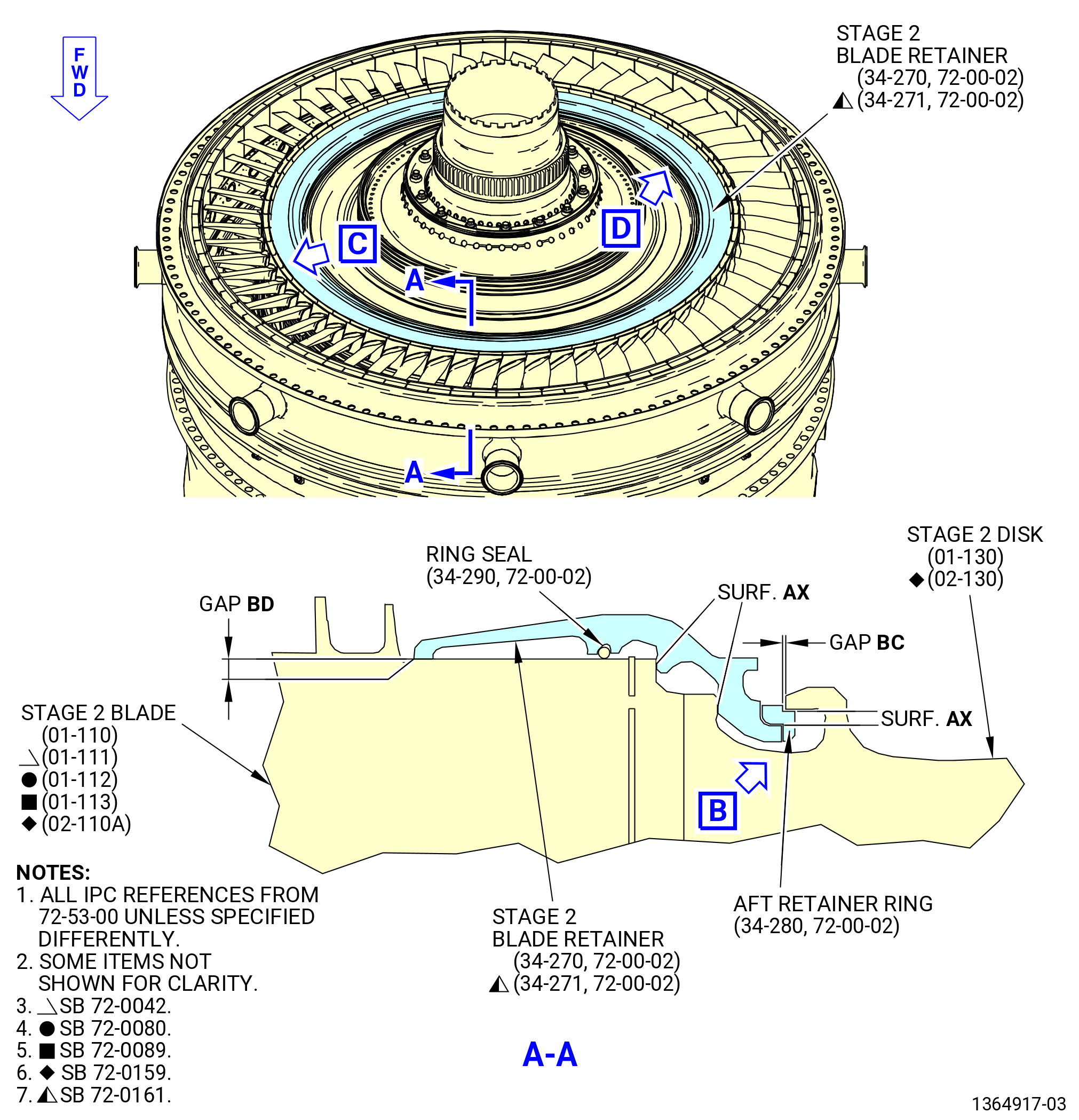
| (3) | Lubricate the aft stage 2 blade retainer and the rear HPT rotor retainer ring (aft retainer ring) (150B7) interface areas (Surfaces AX) with the C02-008 lubricant. Refer to Figure 1020. |
| Subtask 72-50-00-430-097 |
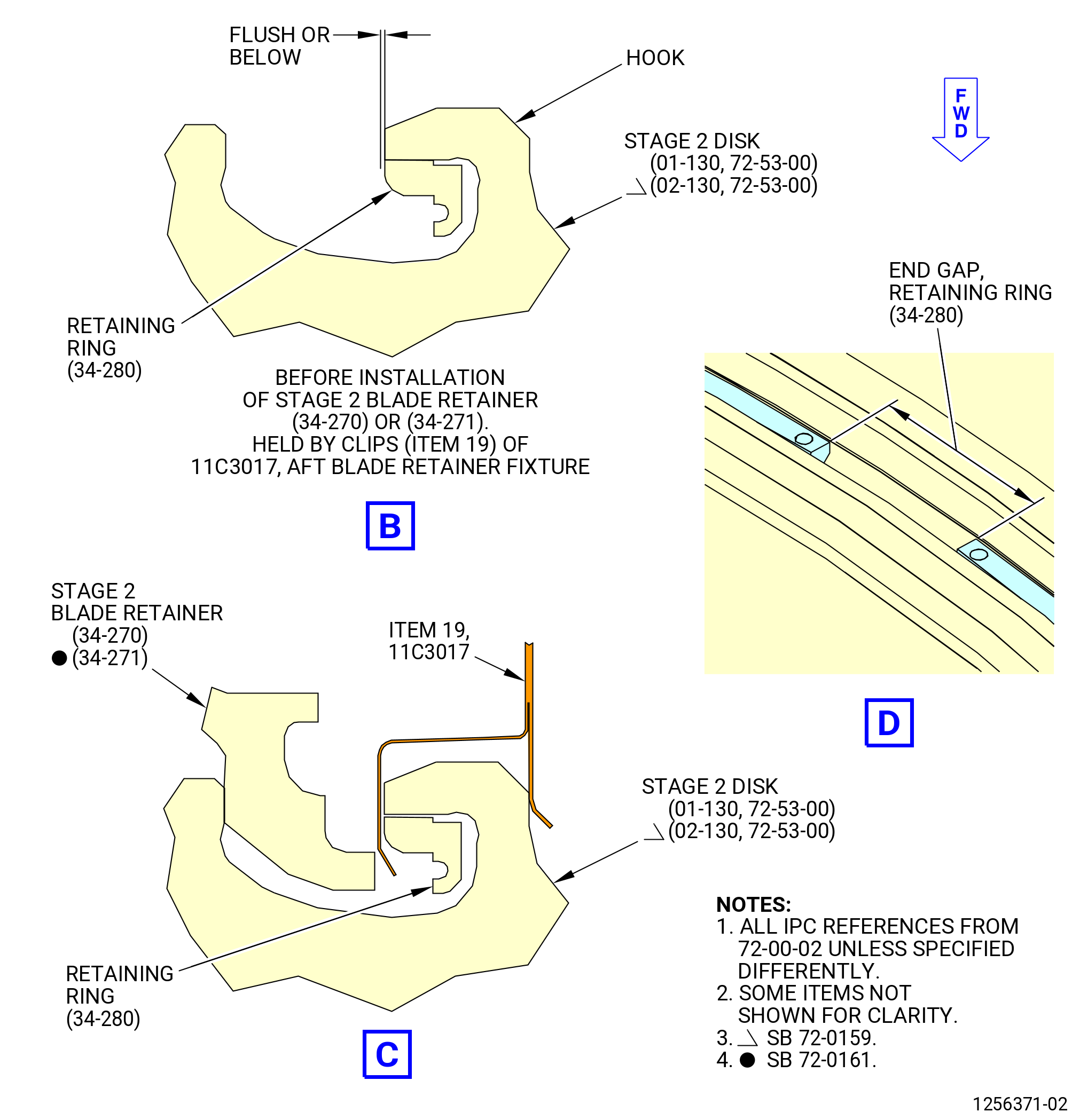
| (4) | Install the aft retainer ring (34-280 , 72-00-02) (SIN 150B7) on the HPTR stage 2 disk (01-130 , 72-53-00) (SIN 150B1) or (02-130 , 72-53-00) (SIN 150B1). Refer to Figure 1020 and do as follows: |
| (a) | Install the aft retainer ring inside the hook on the aft side of the HPTR stage 2 disk (01-130 , 72-53-00) (SIN 150B1) or (02-130 , 72-53-00) (SIN 150B1). |
| NOTE: |
|
| (b) | Compress the aft retainer ring completely inside the hook and install a clip (item 19) of the 11C3017 install/remove fixture around each end of the aft retainer ring end gap. |
| NOTE: |
|
| (c) | Install the remaining clips (item 19) around the aft retainer ring approximately 30 degrees apart. |
| CAUTION: |
|
| (d) | Make sure that the aft retainer ring is flush or below the radial surface of the HPTR stage 2 disk hook. |
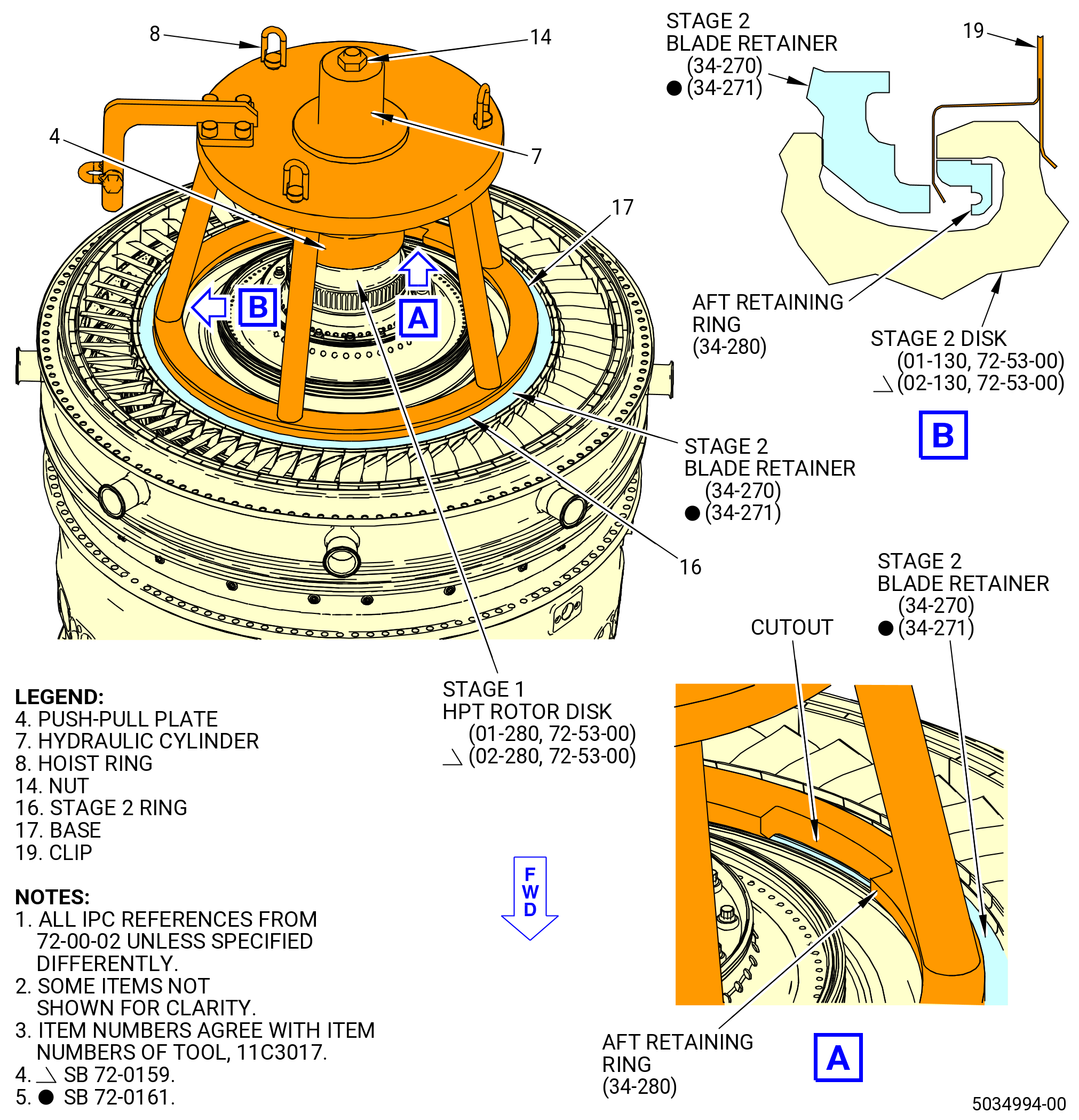
| (5) | Install the aft stage 2 blade retainer (34-270 , 72-00-02) (SIN 150B5) or (34-271 , 72-00-02) (SIN 150B5) on the HPTR stage 2 disk (01-130 , 72-53-00) (SIN 150B1) or (02-130 , 72-53-00) (SIN 150B1) as follows: |
| (a) | Put the stage 2 blade retainer on the HPTR stage 2 disk with the ring seal (150N4) against the HPTR stage 2 disk. |
| (b) | Tap the stage 2 blade retainer lightly with a soft mallet to engage the HPTR stage 2 disk. Make sure that you do not damage the aft retainer ring (150B7). |
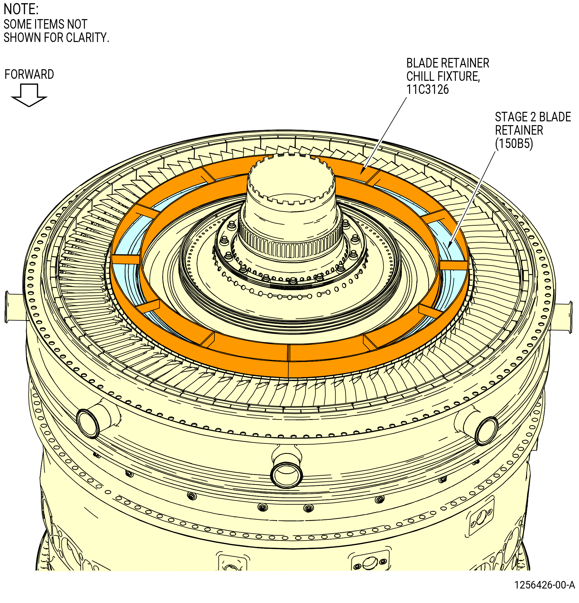
| (c) | Install the 11C3126 chill fixture on the stage 2 blade retainer (150B5) as follows. Refer to Figure 1021. |
| 1 | Carefully put each half of the 11C3126 chill fixture on the aft stage 2 blade retainer. |
| WARNING: |
|
| 2 | Put dry ice in the 11C3126 chill fixture. |
| 3 | Let the temperature of the aft stage 2 blade retainer decrease for 20 minutes. |
| CAUTION: |
|
| (d) | Install the push/pull plate (item 4) of the 11C3017 install/remove fixture on the stage 1 HPT rotor disk (01-280 , 72-53-00) (SIN 150A1) or (02-280 , 72-53-00) (SIN 150A1). Turn the push/pull plate (item 4) CW to install. Do not use too much force to tighten the push-pull plate (item 4). Tighten the push-pull plate (item 4) until it is tight. Refer to Figure 1022. |
| WARNING: |
|
| (e) | After the temperature of the aft stage 2 blade retainer was decreased for 20 minutes, remove the 11C3126 chill fixture and the dry ice. |
| (f) | Install the base (item 17) of the 11C3017 install/remove fixture on the aft stage 2 blade retainer as follows: |
| 1 | Attach an overhead hoist to the hoist rings (item 8). |
| 2 | Align the cutout in the base (item 17) with the split-line gap of the aft retainer ring (150B7). |
| NOTE: |
|
| 3 | Lower the base (item 17) on the aft stage 2 blade retainer (150B5). The stage 2 ring (item 16) that is attached to the base (item 17) will be on the aft stage 2 blade retainer. |
| (g) | Attach the nut (item 14) to the shaft on the push/pull plate (item 4). |
| (h) | Connect a hydraulic pump to the hydraulic cylinder (item 7) of the 11C3017 install/remove fixture. |
| (i) | Put the valve on the hydraulic pump in the PUSH position. |
| (j) | Operate the hydraulic pump three to five full strokes to remove any free movement from the 11C3017 install/remove fixture. |
| (k) | Make sure that the stage 2 ring (item 16) of the 11C3017 install/remove fixture is aligned with the aft stage 2 blade retainer (150B5). |
| CAUTION: |
|
| (l) | Apply up to 7,000 psig (48263 kPa gage) pressure to install the aft stage 2 blade retainer (150B5). When pressure is applied, the 11C3017 install/remove fixture puts a downward pressure on the aft stage 2 blade retainer. |
| (m) | Remove the clips (item 19) of the 11C3017 install/remove fixture. |
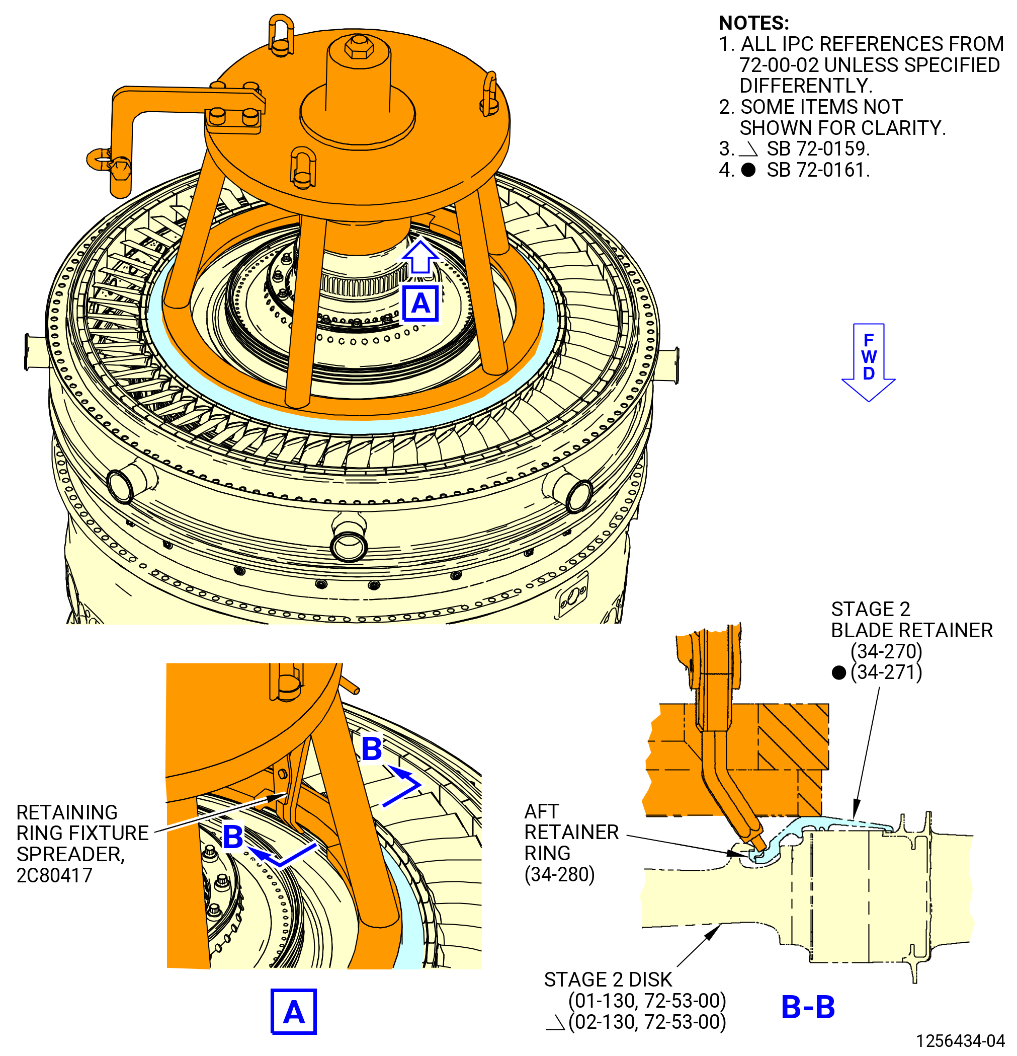
| (n) | Install the 2C80417 retaining ring fixture spreader in the holes on the ends on the aft retainer ring (150B7). Refer to Figure 1023. |
| (o) | Adjust the tool set to move the retainer ring outward (expanded position) around the hook of the HPTR stage 2 disk (01-130 , 72-53-00) (SIN 150B1) or (02-130 , 72-53-00) (SIN 150B1). This will retain the stage 2 blade retainer. |
| (p) | Put the valve on the hydraulic pump in the PULL position. |
| (q) | Operate the hydraulic pump three to five full strokes to release the pressure from the stage 2 blade retainer. |
| (r) | Remove the 2C80417 retaining ring fixture spreader. |
| (s) | Remove the nut (item 14) of the 11C3017 install/remove fixture from the shaft on the push/pull plate (item 4). Refer to Figure 1022. |
| (t) | Attach an overhead hoist to the hoist rings (item 8) and remove the 11C3017 install/remove fixture from the propulsor assembly (30-020 , 72-00-00) (SIN 0010C) or (30-021 , 72-00-00) (SIN 0010C) or (30-022 , 72-00-00) (SIN 0010C) or (30-023 , 72-00-00) (SIN 0010C). |
| CAUTION: |
|
| (u) | Carefully remove the push/pull plate (item 4) from aft end of the stage 1 HPT rotor disk (01-280 , 72-53-00) (SIN 150A1) or (02-280 , 72-53-00) (SIN 150A1). Turn the push/pull plate (item 4) counterclockwise (CCW) to remove. |
| Subtask 72-50-00-220-011 |
| (6) | Examine the correct installation of the aft retainer ring (150B7) and the aft stage 2 blade retainer (150B5) as follows. Refer to Figure 1020. |
| (a) | Make sure that the split-line clearance of the aft retainer ring is 0.680 inch (17.27 mm) or larger and that clearance BC is 0.001 inch (0.03 mm) or larger and as follows: |
| 1 | If the split-line gap and gap BC are smaller, the aft stage 2 blade retainer is not in the correct position in the HPTR stage 2 disk (01-130 , 72-53-00) (SIN 150B1) or (02-130 , 72-53-00) (SIN 150B1) and the aft retainer ring did not expand into the groove of the stage 2 blade retainer. |
| (b) | Use a 0.001 inch (0.03 mm) shim to measure gap BD to make sure that the aft stage 2 blade retainer is completely installed. Check gap BD around the full circumference. A maximum gap of 0.005 inch (0.13 mm) for gap BD is permitted at only two stage 2 blades. |
| Subtask 72-50-00-430-098 |
| (7) | If the aft retainer ring (150B7) or the aft stage 2 blade retainer (150B5) is not correctly installed, do TASK 72-50-00-030-801 (72-50-00, Disassembly 001) to remove the aft stage 2 blade retainer. Do Subtask 72-50-00-140-001 (paragraph 3.I.(2)) thru Subtask 72-50-00-220-011 (paragraph 3.H.(6)) to reinstall the stage 2 blade retainer (150B5). |
| Subtask 72-50-00-220-017 |
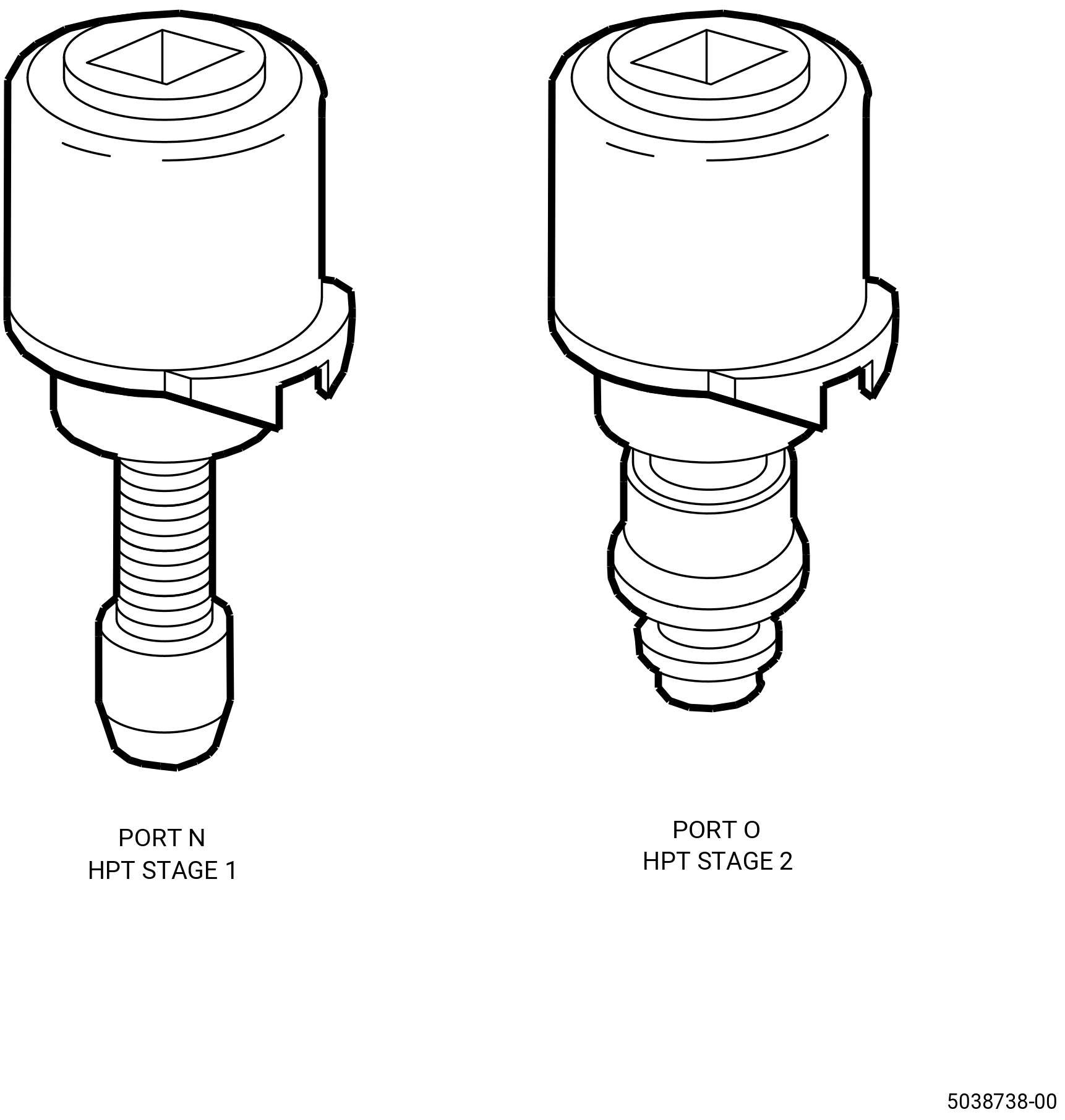
| J. | Do a visual inspection of the borescope plugs and ports. Refer to TASK 72-00-00-800-804 (72-00-00, SPECIAL PROCEDURE 004) (paragraph 5.A. and 5.B.) and Figure 1025. |
| Subtask 72-50-00-430-099 |
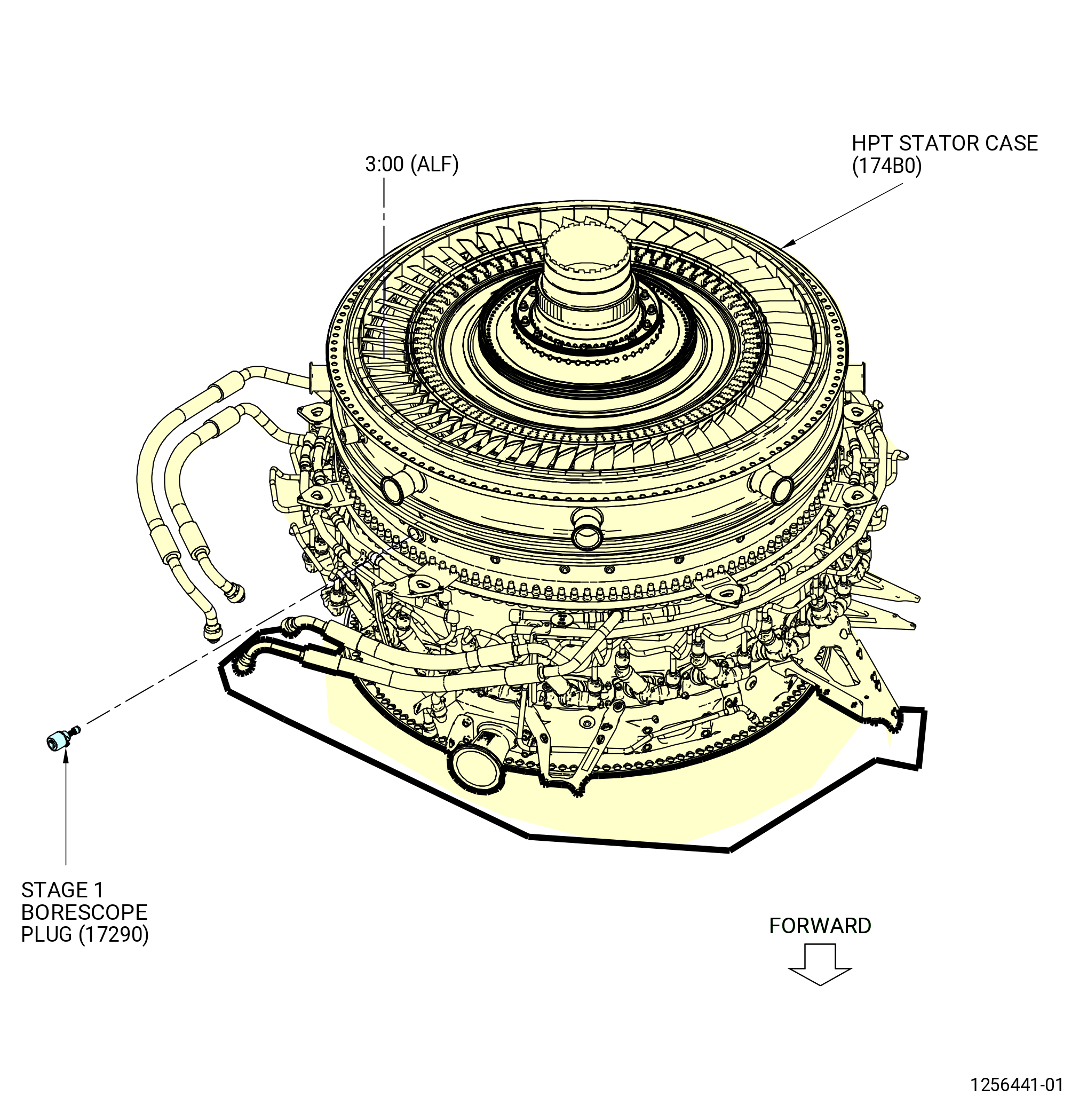
| K. | Install the stage 1 HPT stator borescope plug (stage 1 borescope plug) (17290) in the HPT stator case (174B0) as follows. Refer to Figure 1024. |
| WARNING: |
|
| (1) | Apply C02-097 lubricant or C02-071 lubricant to the mating surfaces and the threads of the stage 1 borescope plug. |
| NOTE: |
|
| (2) | Install the stage 1 borescope plug in the HPT stator case at the 3:00 o'clock position ALF. |
| (3) | Torque the borescope plug to 142.6 to 167.4 lb in. (16.1 to 18.9 Nm), if both borescope plug and HPT stator case are new parts. Torque the borescope plug a second time. |
| NOTE: |
|
| (4) | The maximum running torque is 15.0 lb in. (1.7 Nm), if the borescope plug or the HPT stator case are not a new part. Torque the borescope plug to 142.6 to 167.4 lb in. (16.1 to 18.9 Nm) plus the running torque. Torque the borescope plug a second time. |
| (5) | After the plug has been torqued, do a visual inspection of the plug and make sure that the locking feature is fully engaged with the lug on the borescope boss. Also make sure that the head of the borescope plug is fully seated against the borescope boss. If one of the two conditions are not met, the ratcheting feature of the plug can be seized or locked. Apply a penetrating oil directly in between the locking ring and the head of the plug. Re-apply torque to the plug until the plug begins to rotate freely. Tighten the plug from 142.6 to 167.4 lb in. (16.1 to 18.9 Nm). Do the visual inspection again before proceeding. If the conditions above cannot be met, replace the plug. Refer to Figure 1026. |
| Subtask 72-50-00-430-100 |
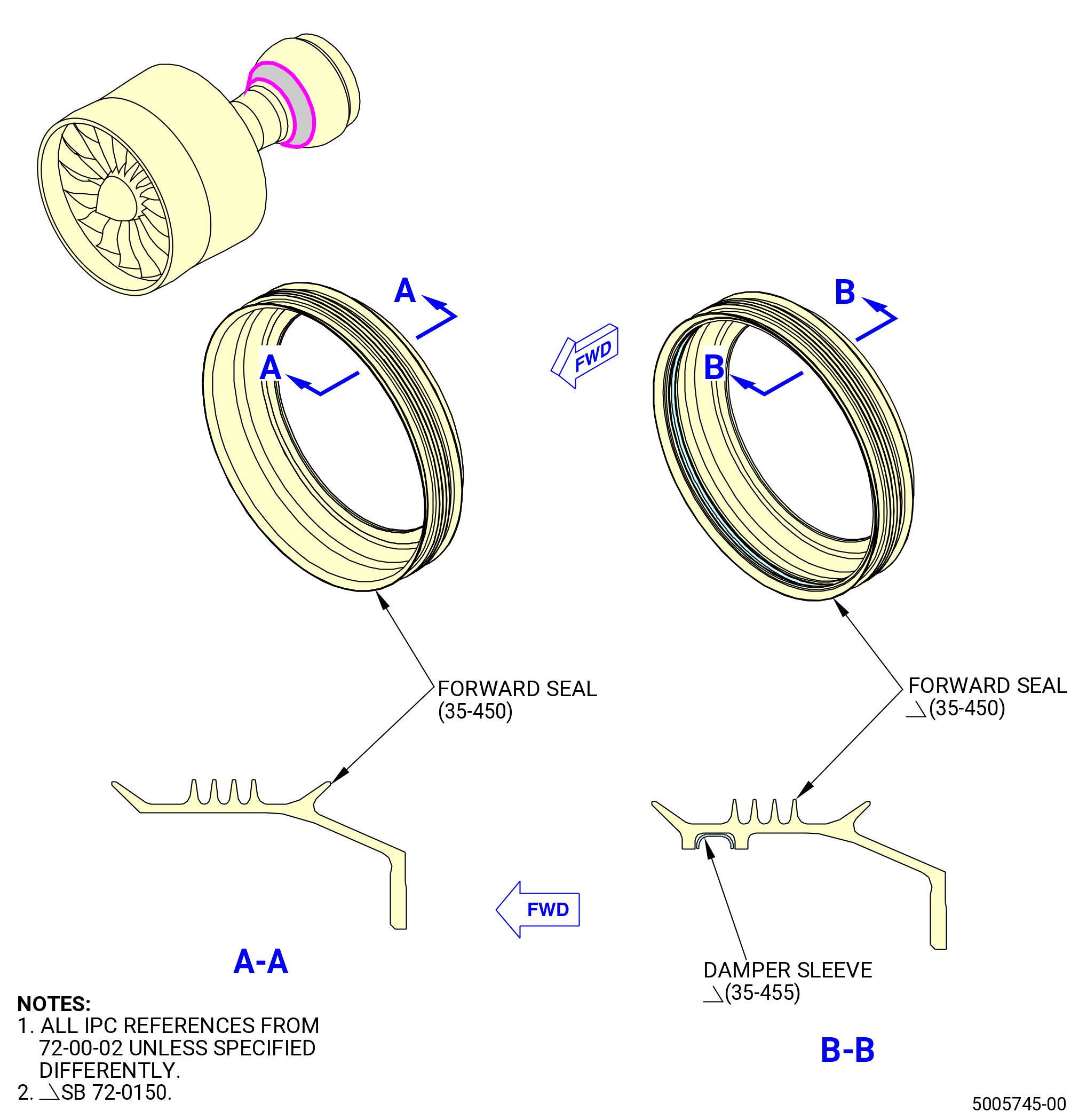
| L. | Install the HPT rotor sump forward seal (forward seal) (35-450 , 72-00-02) (SIN 01401) on the stage 1 HPT rotor disk (01-280 , 72-53-00) (SIN 150A1) or (02-280 , 72-53-00) (SIN 150A1) of the HPT rotor assembly (34-020 , 72-00-02) (SIN 15000) or (34-021 , 72-00-02) (SIN 15000). Refer to Figure 1027 and do as follows: |
| Subtask 72-50-00-430-140 |
| * * * SB 72-0150( Introduction of New Damper Sleeve and Forward Seal ) |
| (1) | Install the damper sleeve (35-455 , 72-00-02) (SIN 01492) to the forward seal (35-450 , 72-00-02) (SIN 01401) as follows: |
| NOTE: |
|
| (a) | Install the damper sleeve in the inner groove of the forward seal. |
| (b) | Do an inspection for axial positioning of the damper sleeve to make sure that it is correctly installed against the forward seal ID. |
| * * * END SB 72-0150( ) |
| Subtask 72-50-00-430-141 |
| (2) | Put the forward seal on the stage 1 HPT rotor disk with the part number in the aft direction. |
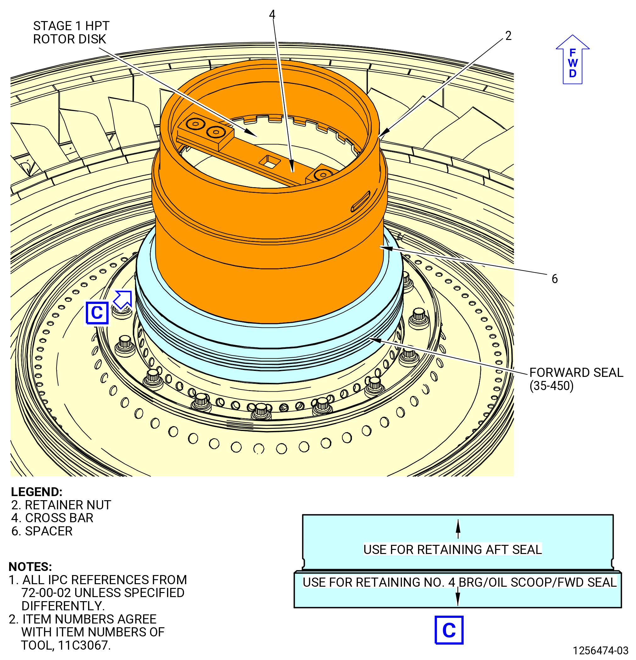
| (3) | Use the 11C3067 retainer fixture to push the forward seal on the stage 1 HPT rotor as follows: |
| (a) | Put the spacer (item 6) on the stage 1 HPT rotor shaft. Make sure that it touches the forward seal. |
| (b) | Put the retainer nut (item 2) with the end that has the mark USE FOR RETAINING NO. 4 BRG/OIL SCOOP/FWD SEAL on the spacer (item 6). |
| (c) | Turn the retainer nut (item 2) CW to thread the retainer on the stage 1 HPT rotor disk. |
| (d) | Use a 0.50 inch (12.7 mm) drive in the center of the cross bar (item 4) to tighten the retainer nut (item 2). Tighten the retainer nut (item 2) until the spacer (item 6) does not move and the forward seal is in the correct position. |
| (4) | Remove the retainer nut (item 2) and the spacer (item 6). |
| Subtask 72-50-00-220-013 |
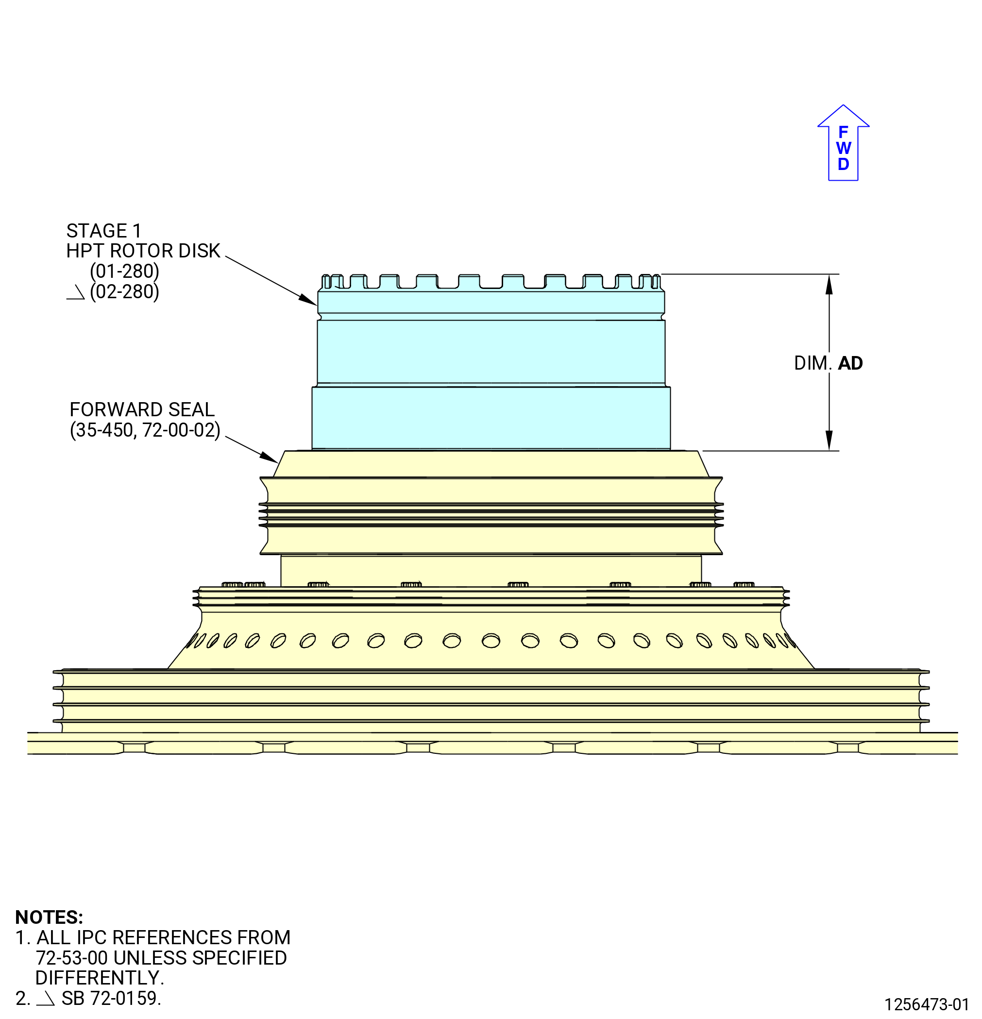
| (5) | Measure the drop (dim AD) from the stage 1 HPT rotor aft end to the forward seal aft flange as follows. Refer to Figure 1028. |
| (a) | Measure the drop at four equally spaced locations. |
| (b) | Record the minimum and the maximum for dim AD. Make sure that the dimension is 3.127-3.157 inches (79.43-80.19 mm). |
| Subtask 72-50-00-430-101 |
| CAUTION: |
|
| CAUTION: |
|
| CAUTION: |
|
| M. | Install the No. 4 cylindrical roller bearing (No. 4 bearing) (15-090 , 72-54-00) (SIN 01400) or (15-091 , 72-54-00) (SIN 01400) inner race on the HPT rotor assembly (34-020 , 72-00-02) (SIN 15000) or (34-021 , 72-00-02) (SIN 15000). Refer to TASK 70-14-00-620-003 (HANDLING OF BEARINGS) and Figure 1029 and do as follows: |
| (1) | Get access to the No. 4 bearing outer race in the turbine frame assembly (35-009 , 72-00-02) (SIN 92500) or (35-010 , 72-00-02) (SIN 92500) or (35-011 , 72-00-02) (SIN 92500) or (35-012 , 72-00-02) (SIN 92500) or (35-015 , 72-00-02) (SIN 92500). If necessary remove the 11C3213 cover or other covering from the bearing area. |
| (2) | Make sure that the No. 4 bearing inner and outer race serial numbers match. |
| WARNING: |
|
| (3) | Use a lint free C10-182 cleaning cloth to apply a light layer of C02-019 engine oil or C02-023 engine oil on No. 4 bearing inner race and the stage 1 HPT rotor disk (01-280 , 72-53-00) (SIN 150A1) or (02-280 , 72-53-00) (SIN 150A1) in the area where the No. 4 bearing inner race will be installed (area P). |
| Subtask 72-50-00-430-102 |
| WARNING: |
|
| CAUTION: |
|
| (4) | Increase the temperature of the No.4 bearing inner race with an induction heater to 350°F (177°C), maximum 400°F (204°C). Use a temperature probe to check the temperature of the inner race. |
| CAUTION: |
|
| (5) | Put the No. 4 bearing inner race on the stage 1 HPT rotor (01-280 , 72-53-00) (SIN 150A1) or (02-280 , 72-53-00) (SIN 150A1) with the puller groove in the aft direction. |
| (6) | Use the 11C3067 retainer fixture to push the No. 4 bearing inner race on the stage 1 HPT rotor as follows: |
| (a) | Put the spacer (item 3) on the stage 1 HPT rotor shaft. Make sure that the spacer touches the inner race. |
| (b) | Put the retainer nut (item 2) with the end that has the mark USE FOR RETAINING NO. 4 BRG/OIL SCOOP/FWD SEAL on the spacer (item 3). |
| (c) | Turn the retainer nut (item 2) CW to thread the retainer on the stage 1 HPT rotor disk. |
| (d) | Use a 0.50 inch (12.7 mm) drive in the center of the cross bar (item 4) to tighten the retainer nut (item 2). Tighten the retainer nut (item 2) until the spacer (item 3) does not move and the No. 4 bearing inner race is in the correct position. |
| (7) | Let the temperature of the No. 4 bearing inner race decrease to room temperature. |
| (8) | Remove the retainer nut (item 2) and the spacer (item 3). |
| Subtask 72-50-00-220-014 |
| (9) | Examine the shims to make sure that the No. 4 bearing inner race is correctly installed on the stage 1 HPT rotor shaft as follows: |
| (a) | Use a 0.001 inch (0.03 mm) shim stock. |
| (b) | Make sure that the shim stock cannot go between the No. 4 bearing inner race and the forward seal (01401). |
| (c) | Examine the shims at four equally spaced locations. |
| Subtask 72-50-00-430-104 |
| N. | Install the turbine frame assembly (35-009 , 72-00-02) (SIN 92500) or (35-010 , 72-00-02) (SIN 92500) or (35-011 , 72-00-02) (SIN 92500) or (35-012 , 72-00-02) (SIN 92500) or (35-015 , 72-00-02) (SIN 92500) on the propulsor assembly (30-020 , 72-00-00) (SIN 0010C) or (30-021 , 72-00-00) (SIN 0010C) or (30-022 , 72-00-00) (SIN 0010C) or (30-023 , 72-00-00) (SIN 0010C) as follows: |
| Subtask 72-50-00-430-122 |
| CAUTION: |
|
| (1) | Install the 11C3159 guide on the stage 1 HPT rotor disk (01-280 , 72-53-00) (SIN 150A1) or (02-280 , 72-53-00) (SIN 150A1). Refer to Figure 1030. |
| Subtask 72-50-00-220-016 |
| (2) | Do a visual inspection of the HPT Stator Case (174B0) aft cavities for foreign object damage (FOD). |
| Subtask 72-50-00-430-121 |
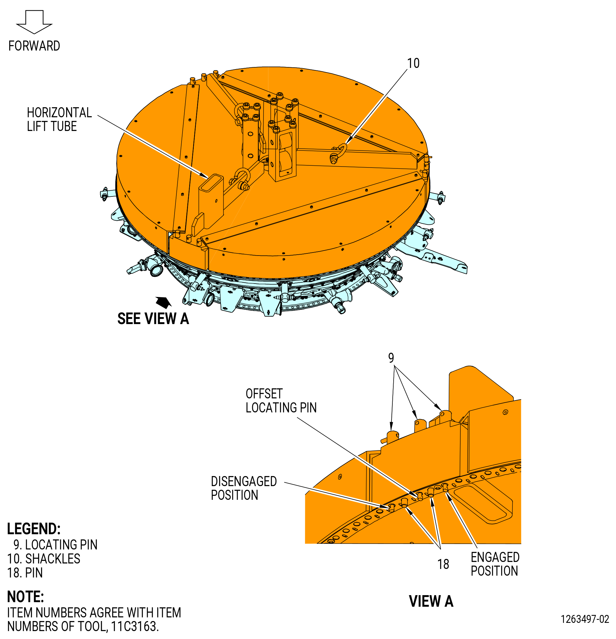
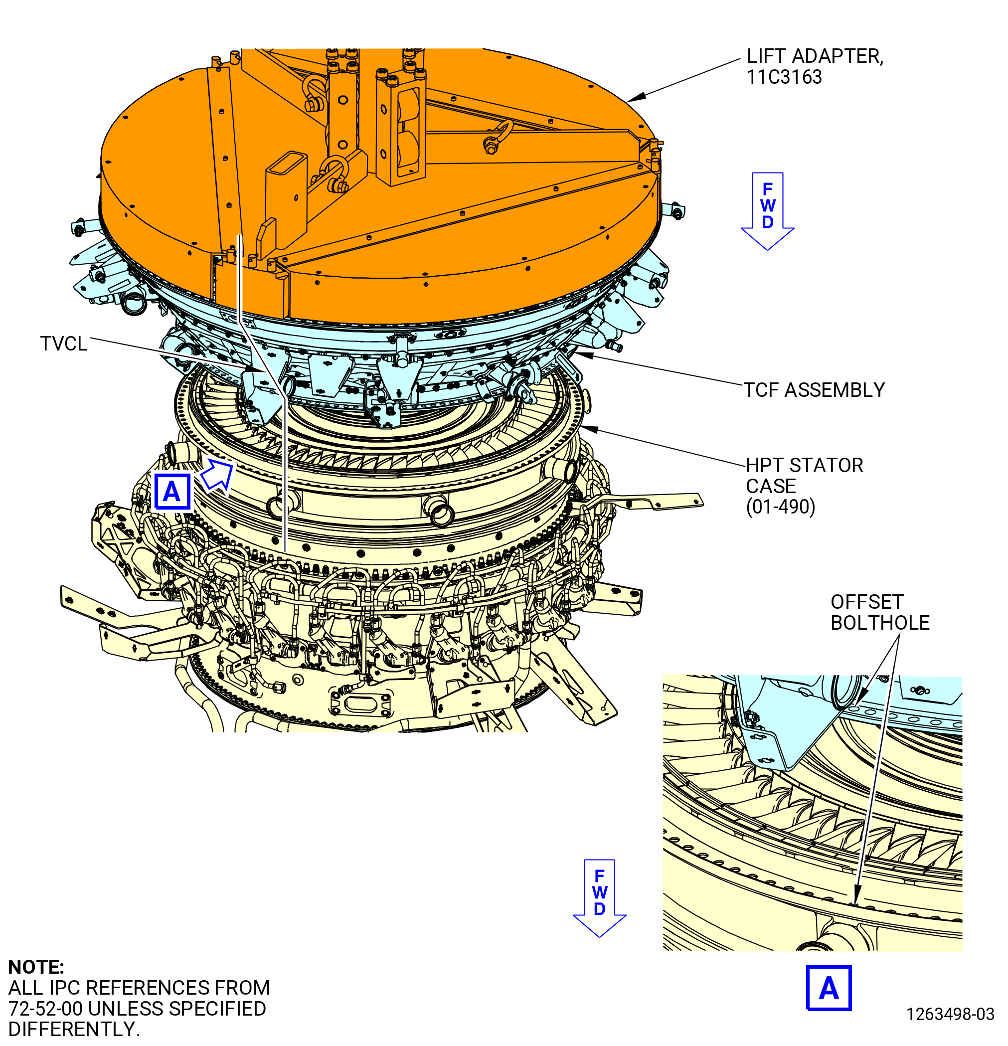
| (3) | Install the 11C3163 lift adapter to the turbine frame assembly as follows. Refer to Figure 1031. |
| (a) | Attach a three-legged sling to the three shackles (item 10) of the 11C3163 lift adapter. |
| (b) | Turn the nine locating pins (item 9) so the pin points out to the disengaged position. |
| WARNING: |
|
| (c) | Lift the 11C3163 lift adapter with an overhead hoist and put it over the turbine frame assembly with the horizontal lift tube at TVCL. |
| NOTE: |
|
| (d) | Lower the lift adapter on the turbine frame assembly. Align the pins (item 18) and the locating pins (item 9) to the flange boltholes. Make sure that the offset bolthole and offset locating pin (item 9) are aligned. |
| (e) | Rotate the nine locating pins (item 9) so the pin points inward to the engaged position. |
| Subtask 72-50-00-430-106 |
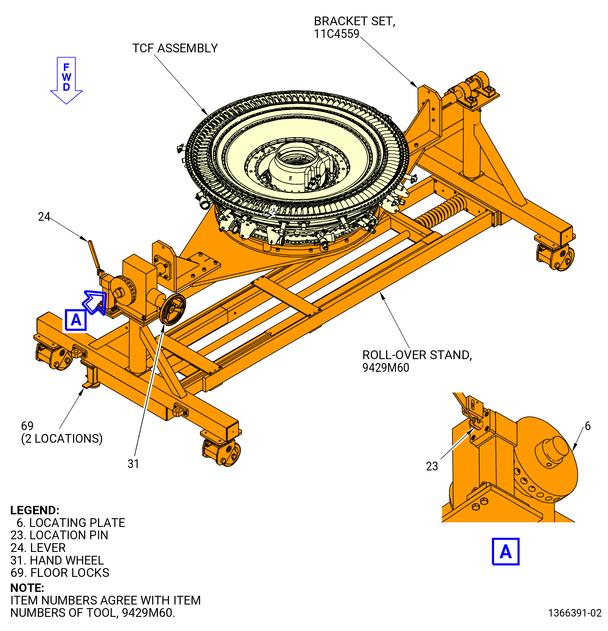
| (4) | Remove the turbine frame assembly from the 11C4559 bracket set installed on the 9429M60 roll-over stand as follows. Refer to Figure 1032. |
| CAUTION: |
|
| (a) | Lower the floor locks (item 69) of the 9429M60 roll-over stand until they touch the floor. The floor locks must stay in contact with the floor to prevent movement of the roll-over stand. Make sure that the roll-over stand is level. |
| WARNING: |
|
| (b) | Lift the turbine frame assembly to remove the weight from the 11C4559 bracket set. |
| (c) | Remove the plain nuts (item 9) and the caps crews (item 8) of the 11C4559 bracket set from the turbine frame assembly forward flange. |
| WARNING: |
|
| (d) | Lift the turbine frame assembly from the 11C4559 bracket set on the 9429M60 roll-over stand. |
| Subtask 72-50-00-430-107 |
| (5) | Slowly lower the turbine frame assembly on the HPT stator case (174B0) aft flange. Carefully engage the No. 4 bearing (15-090 , 72-54-00) (SIN 01400) or (15-091 , 72-54-00) (SIN 01400) outer race with the roller assembly. |
| (6) | Align the turbine frame assembly TVCL to the HPT stage 2 nozzle assembly (34-010 , 72-00-02) (SIN 17400) or (34-011 , 72-00-02) (SIN 17400) or (34-012 , 72-00-02) (SIN 17400) TVCL. Make sure that the off-set boltholes are aligned. |
| NOTE: |
|
| (7) | Remove the 11C3163 lift adapter from the turbine frame assembly as follows. Refer to Figure 1033. |
| (a) | Remove the six 0.375-16 UNC-3B bolts and six pins (item 18) that attach the 11C3163 lift adapter to the turbine frame assembly. |
| (b) | Attach a three-legged sling to the three shackles (item 10) of the 11C3163 lift adapter. |
| WARNING: |
|
| (c) | Lift the 11C3163 lift adapter with an overhead hoist and remove it from the turbine frame assembly. |
| (8) | Remove the 11C3159 guide from the stage 1 HPT rotor disk (01-280 , 72-53-00) (SIN 150A1) or (02-280 , 72-53-00) (SIN 150A1). |
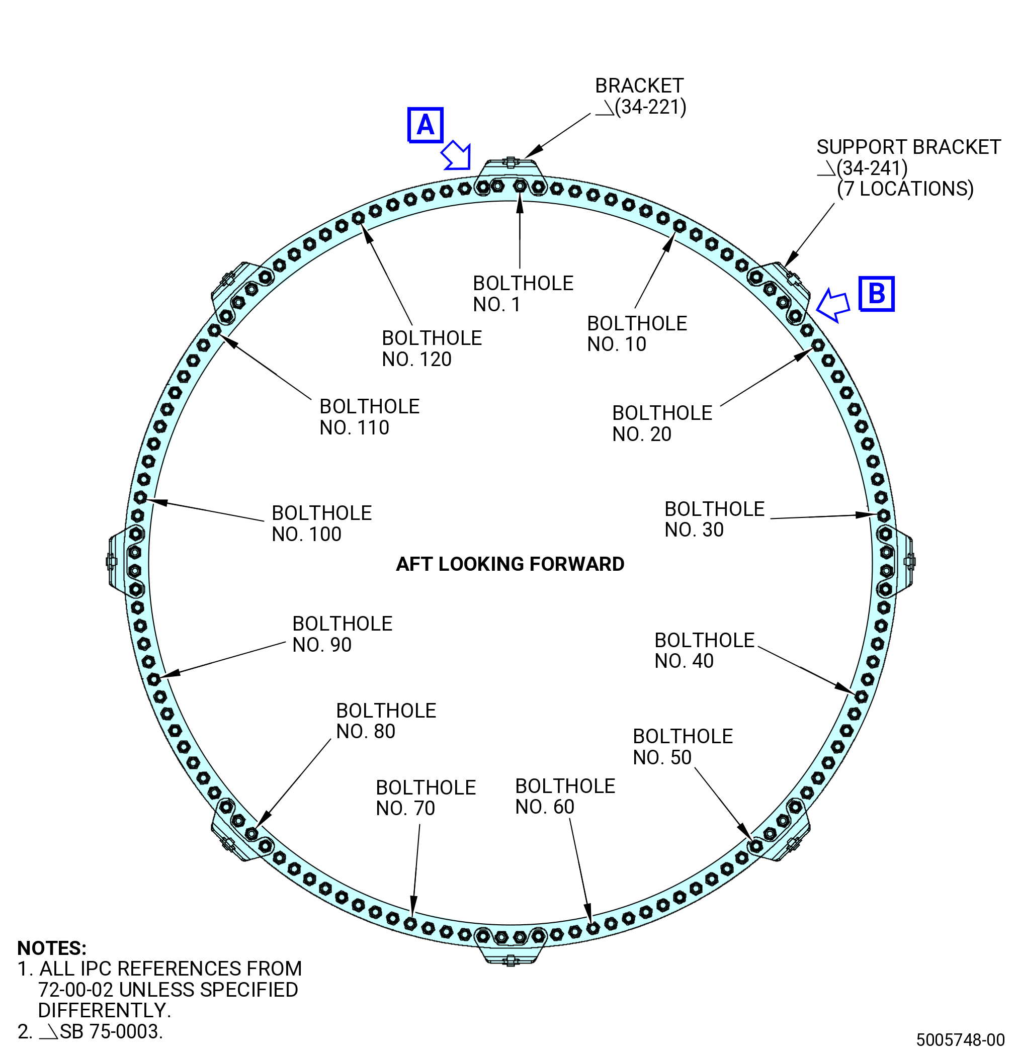
| (9) | On the forward flange of the turbine frame assembly, put a number every ten boltholes with a C05-003 pen in a CW direction ALF. Refer to Figure 1034. |
| WARNING: |
|
| (10) | Apply C02-058 lubricant to the mating surfaces and threads on the nuts (34-200 , 72-00-02) (SIN 92540) and the bolts (34-180 , 72-00-02) (SIN 92520). Make sure that there is lubricant in the V-groove of the threads. |
| (11) | Attach the TCF assembly (35-009 , 72-00-02) (SIN 92500) or (35-010 , 72-00-02) (SIN 92500) or (35-011 , 72-00-02) (SIN 92500) or (35-012 , 72-00-02) (SIN 92500) or (35-015 , 72-00-02) (SIN 92500) to the HPT stator case (01-490 , 72-52-00) (SIN 174B0) with 16 bolts (34-180 , 72-00-02) (SIN 92520) and 16 nuts (34-200 , 72-00-02) (SIN 92540) in the boltholes No. 1, 16, 17, 32, 33, 48, 49, 64, 65, 80, 81, 96, 97, 112, 113, and 128 with the boltheads aft. Hand-tighten the nuts. |
| Subtask 72-50-00-430-142 |
| * * * PRE SB 75-0003( HPTACC without Brackets Reduction ) |
| (12) | Install the support bracket (34-230 , 72-00-02) (SIN 62110) and bracket (34-210 , 72-00-02) (SIN 62111) on the turbine frame assembly forward flange and the HPT stator case (01-490 , 72-52-00) (SIN 174B0) aft flange as follows: |
| NOTE: |
|
| (a) | Install the bracket (34-210 , 72-00-02) (SIN 62111) in the boltholes No. 2 and 127 on the forward side of the flanges. Attach with the bolts (34-190 , 72-00-02) (SIN 92521) and nuts (34-200 , 72-00-02) (SIN 92540) with the bolthead forward. Hand-tighten the nuts. |
| (b) | Install the 15 support brackets (34-230 , 72-00-02) (SIN 62110) on the forward side of the flanges in the boltholes No. 7 and 10, 15 and 18, 23 and 26, 31 and 34, 39 and 42, 47 and 50, 55 and 58, 63 and 66, 71 and 74, 79 and 82, 87 and 90, 95 and 98, 103 and 106, 111 and 114, 119 and 122. Attach with the bolts (34-190 , 72-00-02) (SIN 92521) and nuts (34-200 , 72-00-02) (SIN 92540) with the bolthead forward. Hand-tighten the nuts. |
| * * * END PRE SB 75-0003( ) |
| Subtask 72-50-00-430-143 |
| * * * SB 75-0003( HPTACC with Brackets Reduction ) |
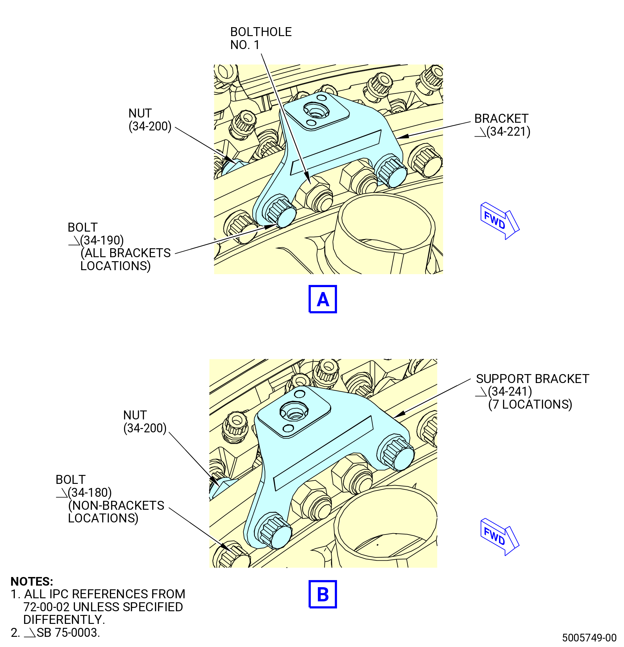
| (12).A. | Install the support bracket (34-241 , 72-00-02) (SIN 62110) and bracket (34-221 , 72-00-02) (SIN 62111) on the turbine frame assembly forward flange and the HPT stator case (01-490 , 72-52-00) (SIN 174B0) aft flange. Refer to Figure 1034A and do as follows: |
| NOTE: |
|
| (a) | Install the bracket (34-221 , 72-00-02) (SIN 62111) in the boltholes No. 2 and 127 on the forward side of the flanges. |
| (b) | Attach the bracket (34-221 , 72-00-02) (SIN 62111) with bolts (34-190 , 72-00-02) (SIN 92521) and nuts (34-200 , 72-00-02) (92540) with the boltheads forward. Hand-tighten the nuts. |
| (c) | Install the seven support brackets (34-241 , 72-00-02) (SIN 62110) on the forward side of the flanges in the boltholes No. 15 and 18, 31 and 34, 47 and 50, 63 and 66, 79 and 82, 95 and 98, 111 and 114. |
| (d) | Attach the support brackets (34-241 , 72-00-02) (SIN 62110) with bolts (34-190 , 72-00-02) (SIN 92521) and nuts (34-200 , 72-00-02) (SIN 92540) with the boltheads forward. Hand-tighten the nuts. |
| * * * END SB 75-0003( ) |
| Subtask 72-50-00-430-144 |
| (13) | Install the bolts (34-180 , 72-00-02) (SIN 92520) and nuts (34-200 , 72-00-02) (SIN 92540) in the remaining boltholes with the boltheads forward. Hand-tighten the nuts. |
| NOTE: |
|
| (14) | Torque the 16 equally spaced nuts (34-200 , 72-00-02) (SIN 92540) in a criss-cross pattern to 276-324 lb in. (31.2-36.6 N.m). |
| (15) | Torque the 128 nuts (34-200 , 72-00-02) (SIN 92540) in a criss-cross pattern to 368-432 lb in. (41.6-48.8 N.m). |
| (16) | Torque the 128 nuts (34-200 , 72-00-02) (SIN 92540) in a circle pattern to 368-432 lb in. (41.6-48.8 N.m). |
|
|
|
|
| Subtask 72-50-00-430-108 |
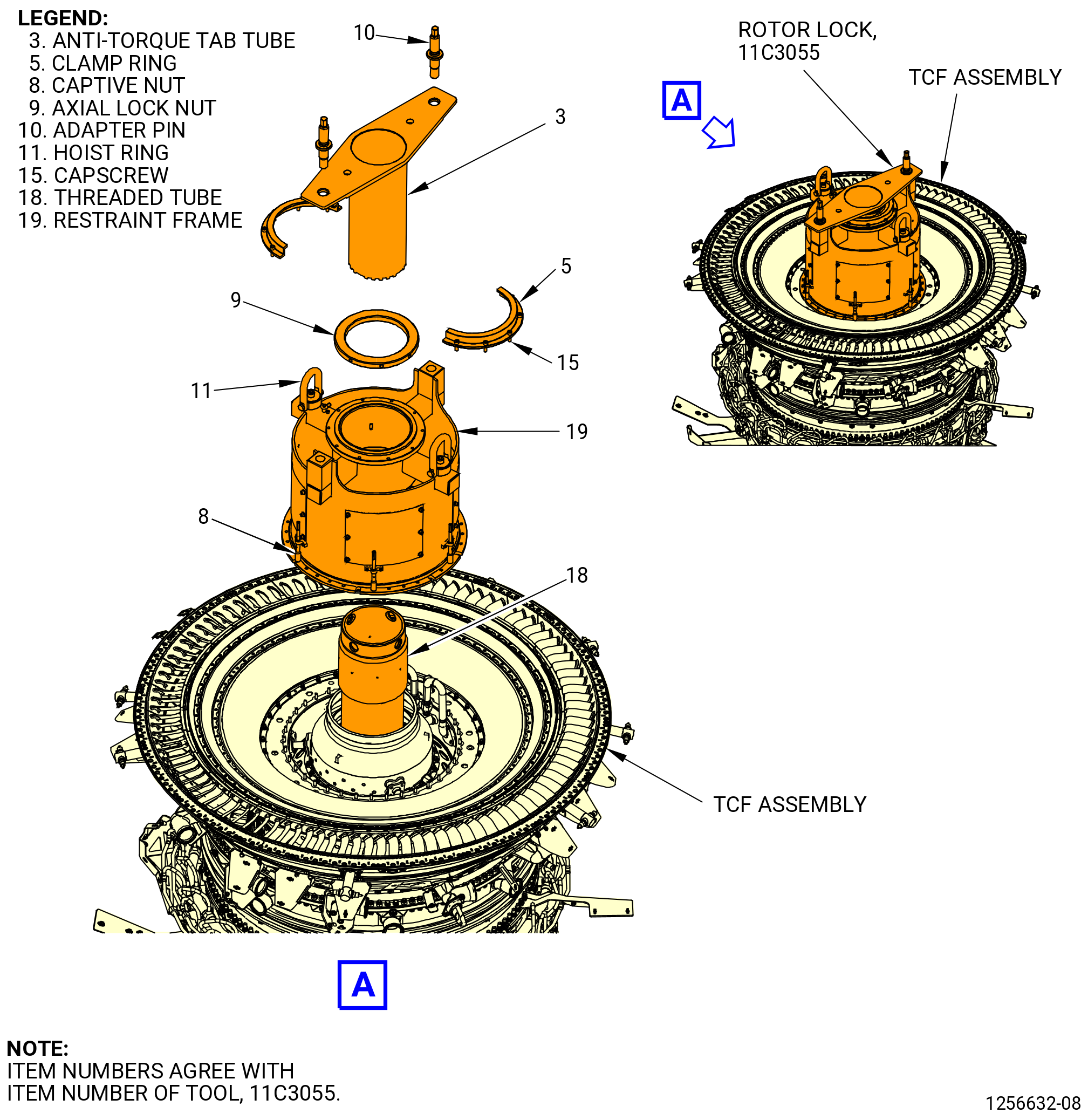
| O. | Install the 11C3055 rotor lock on the aft end of the turbine frame assembly (35-009 , 72-00-02) (SIN 92500) or (35-010 , 72-00-02) (SIN 92500) or (35-011 , 72-00-02) (SIN 92500) or (35-012 , 72-00-02) (SIN 92500) or (35-015 , 72-00-02) (SIN 92500). Refer to Figure 1035 and do as follows: |
| (1) | Install the threaded tube (item 18) as follows: |
| (a) | Put a leverage bar through the 1.00 inch (25.4 mm) diameter holes at the aft end of the threaded tube (item 18). |
| (b) | Thread the forward end of the threaded tube (item 18) into the aft end of the stage 1 HPT rotor disk (01-280 , 72-53-00) (SIN 150A1) or (02-280 , 72-53-00) (SIN 150A1). |
| (c) | Remove the leverage bar from threaded tube (item 18). |
| (2) | Attach a lift strap to the hoist rings (item 11) on the restraint frame (item 19). |
| (3) | Use an overhead hoist to lift the 11C3055 rotor lock and align the holes on the restraint ring of the restraint frame (item 19) with the studs on the turbine frame assembly. Lower the HPT rotor lock to the turbine frame assembly. |
| (4) | Install the captive nuts (item 8) equally spaced on the studs of the turbine frame assembly. |
| (5) | Torque the captive nuts (item 8) to 10 lb ft (13.56 N.m). |
| (6) | Remove the lift strap and overhead hoist from the hoist rings (item 11). |
| (7) | Install the axial lock nut (item 9) on the aft end of the threaded tube (item 18), but do not tighten. |
| (8) | Put the anti-torque tube (item 3) in the threaded tube (item 18) and engage the slots in the stage 1 HPT rotor disk (01-280 , 72-53-00) (SIN 150A1) or (02-280 , 72-53-00) (SIN 150A1). |
| (9) | Put the adapter pins (item 10) in the anti-torque tube (item 3) and thread into the restraint frame (item 19). There must be a 0.125 inch (3.18 mm) gap between the anti-torque tube (item 3) and the restraint frame (item 19) when the adapter pins (item 10) are installed. |
| (10) | Tighten the axial locknut (item 9) with a spanner wrench. |
| (11) | Install the two segments of the clamp ring (item 5) to the restraint frame (item 19) with 10 capscrews (item 15). |
| (12) | Torque the capscrews (item 15) to 120 lb in (13.56 N.m). |
| Subtask 72-50-00-430-109 |
| P. | Install the 11C3025 strongback to the aft end of the turbine frame assembly (35-009 , 72-00-02) (SIN 92500) or (35-010 , 72-00-02) (SIN 92500) or (35-011 , 72-00-02) (SIN 92500) or (35-012 , 72-00-02) (SIN 92500) or (35-015 , 72-00-02) (SIN 92500). Refer to Figure 1036 and do as follows: |
| (1) | Attach the 7C2015 lift/turn fixture to the 11C3025 strongback with the pins (item 3) of the 7C2015 lift/turn fixture. |
| WARNING: |
|
| (2) | Lift the 11C3025 strongback and align the TVCL of the strongback with the aft end of the turbine frame assembly. |
| (3) | Carefully lower the 11C3025 strongback on the turbine frame assembly aft flange and engage the alignment pins in the flange boltholes at the 12:00 o'clock and 6:00 o'clock position. |
| (4) | Attach the 11C3025 strongback to the turbine frame assembly aft flange with the capscrews (item 29) and washers (item 26) at 26 locations. Tighten the capscrews (item 29). |
| Subtask 72-50-00-430-127 |
| Q. | If the 11C3051 CDN dummy case was used, remove the HPT section from the CDN dummy case and install it on the CDN assembly as follows: |
| WARNING: |
|
| (1) | Lift the HPT module buildup with the 7C2015 lift/turn fixture. |
| (a) | Make sure that the 11C3055 rotor lock is installed. |
| (2) | Install the CDN assembly on the 11C3010 build-up fixture. Refer to TASK 72-40-00-440-801 (72-40-00, ASSEMBLY 001). |
| (3) | Install the HPT module buildup on the CDN assembly as follows: |
| (a) | Find the "L" mark on the HPT rotor assembly (34-020 , 72-00-02) (SIN 15000) or (34-021 , 72-00-02) (SIN 15000) outside diameter. |
| (b) | Align the "L" mark on the HPT rotor assembly with the TVCL of the 11C3010 build-up fixture. |
| (c) | Slowly lower the HPT rotor assembly into the CDN assembly. Align the TVCL and off-set boltholes of the HPT stage 2 nozzle assembly (34-010 , 72-00-02) (SIN 17400) or (34-011 , 72-00-02) (SIN 17400) or (34-012 , 72-00-02) (SIN 17400) with the TVCL and off-set boltholes of the CDN assembly. |
| (d) | Engage the bolts (01-060 , 72-41-00) (SIN 12024) in the CDN assembly aft flange through the boltholes in the HPT stage 2 nozzle assembly (34-010 , 72-00-02) (SIN 17400) or (34-011 , 72-00-02) (SIN 17400) or (34-012 , 72-00-02) (SIN 17400). Make sure that the off-set boltholes are aligned. |
| (4) | Install the brackets on the CDN assembly and HPT stage 2 nozzle assembly (34-010 , 72-00-02) (SIN 17400) or (34-011 , 72-00-02) (SIN 17400) or (34-012 , 72-00-02) (SIN 17400) flange. Refer to Subtask 72-50-00-430-092 (paragraph 3.G.). |
| Subtask 72-50-00-510-001 |
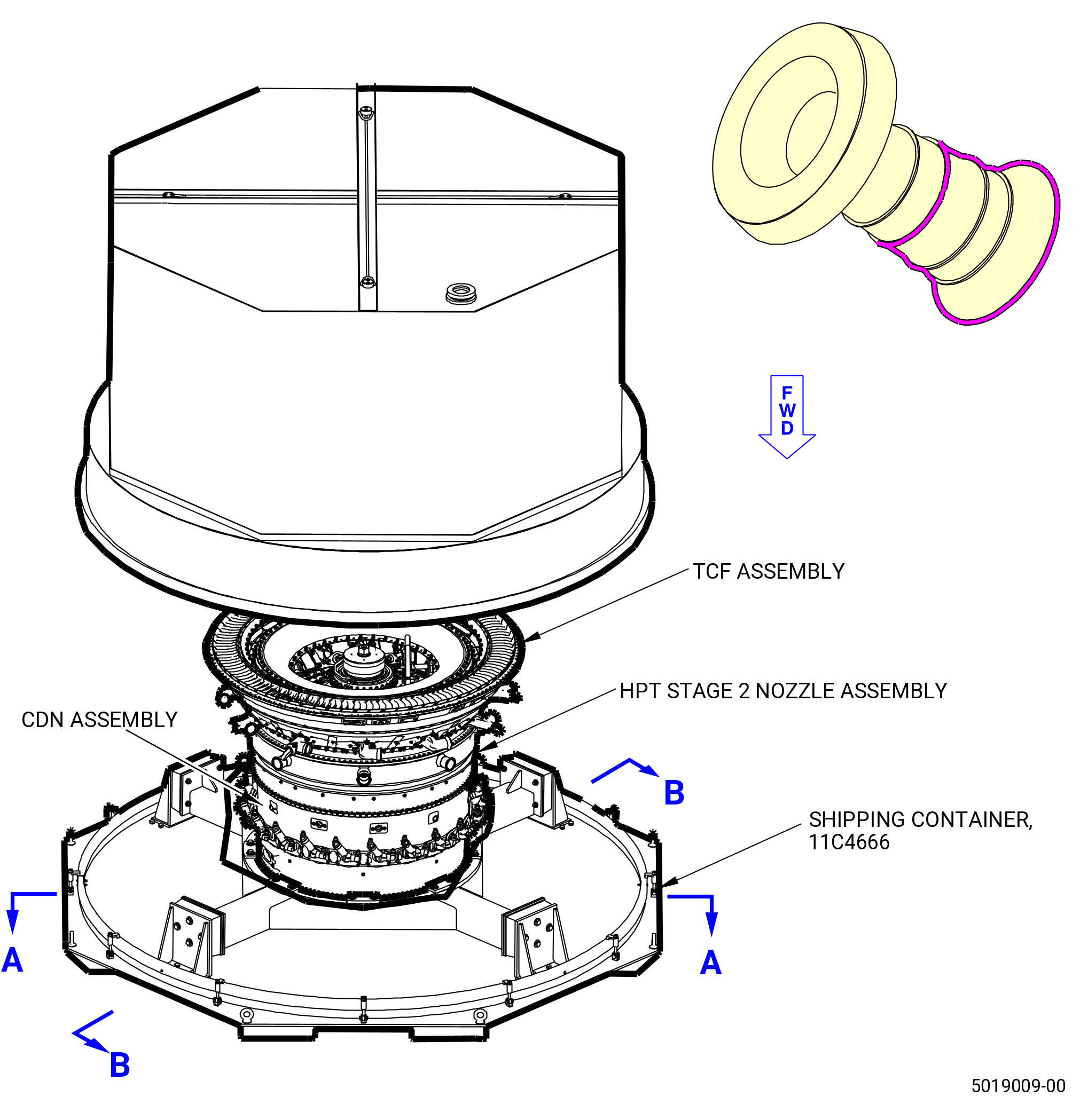
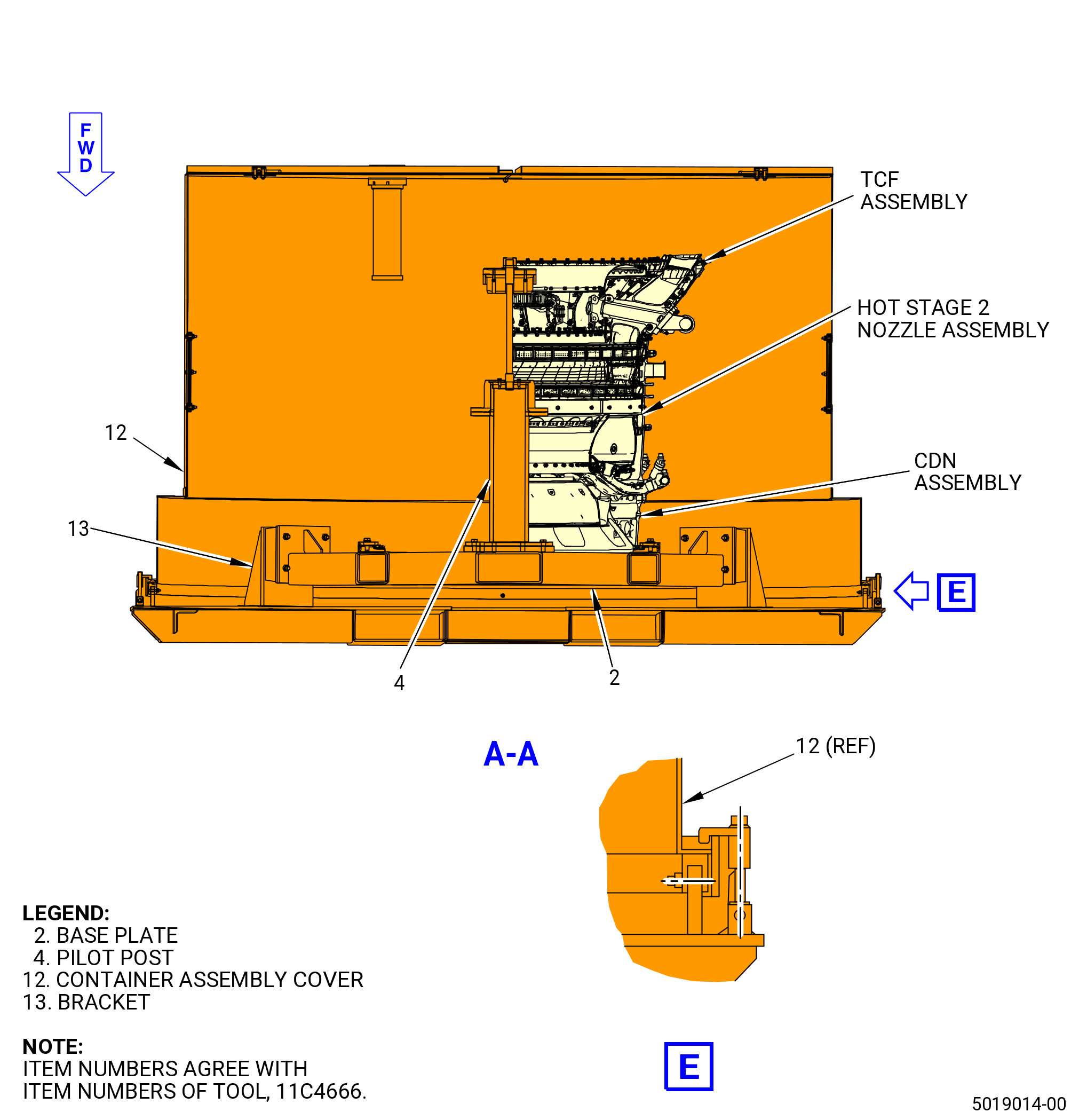
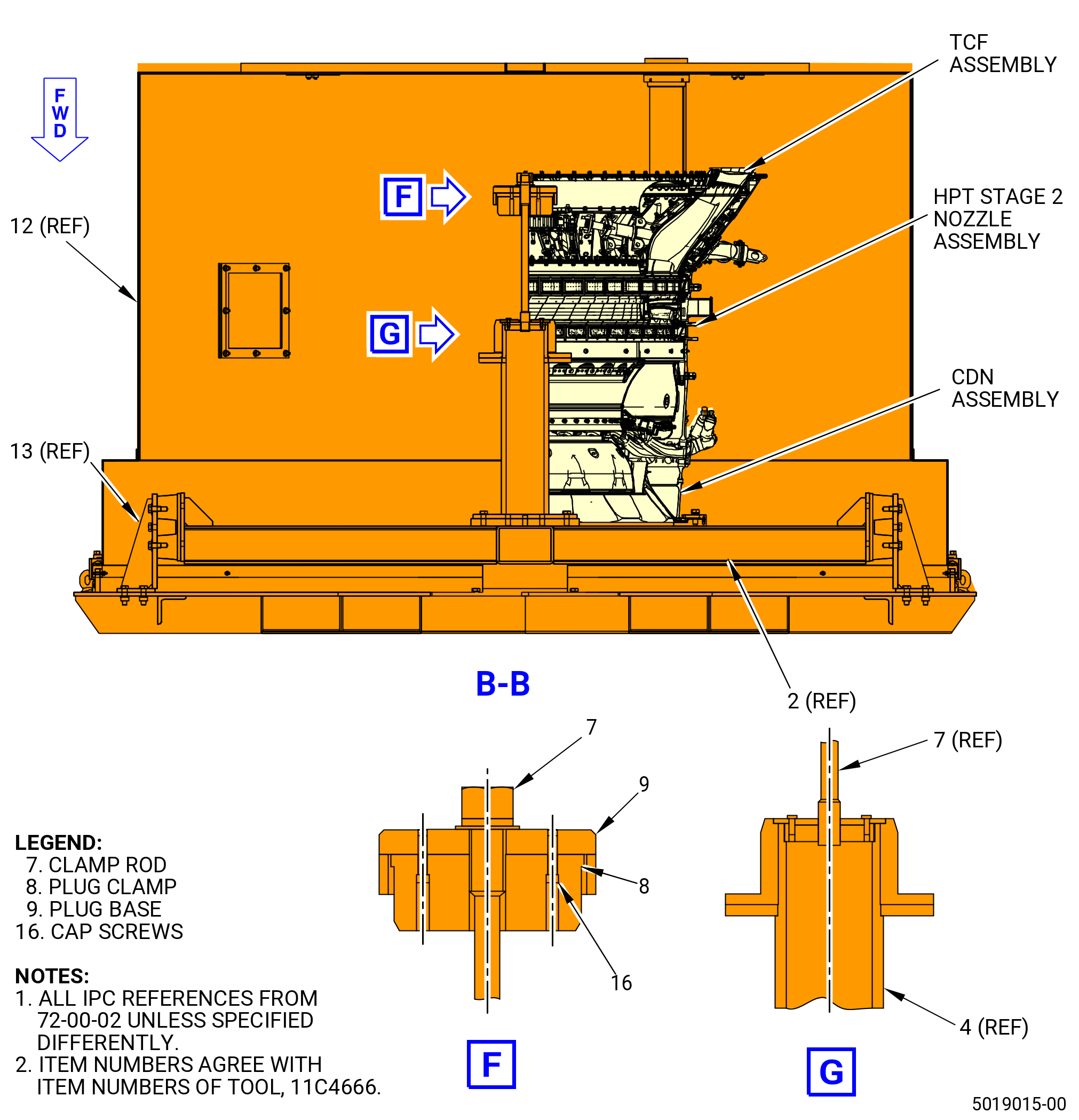
| R. | If the HPT module is to be transported to another facility, put the module in the 11C4666 shipping container. Refer to Figure 1037 and do as follows: |
| (1) | Remove the container assembly cover (item 12) of the 11C4666 shipping container. |
| WARNING: |
|
| (2) | Lift the HPT module and put it on the base plate (item 2) and firmly attach it with four brackets (item 13). |
| (3) | To hold the rotor, install the plug clamp (item 8), plug base (item 9) and 0.25-20 cap screws (item 16), then install the clamp rod (item 7) into the top of the pilot post (item 4) and tighten it to hold the rotor. |
| (4) | Put desiccant bags in the container. |
| (5) | Install the container assembly cover (item 12) and keep it in place with the clamp assemblies P/N (9426M22P10). |