| GENX-1B ENGINE MANUAL | Dated: 03/19/2025 | |
| EM 72-50-00 , DISASSEMBLY 001 | ||
| HIGH PRESSURE TURBINE MODULE - DISASSEMBLY 001 | ||
| GENX-1B ENGINE MANUAL | Dated: 03/19/2025 | |
| EM 72-50-00 , DISASSEMBLY 001 | ||
| HIGH PRESSURE TURBINE MODULE - DISASSEMBLY 001 | ||
| * * * FOR ALL |
| TASK 72-50-00-030-801 |
| 1 . | General. |
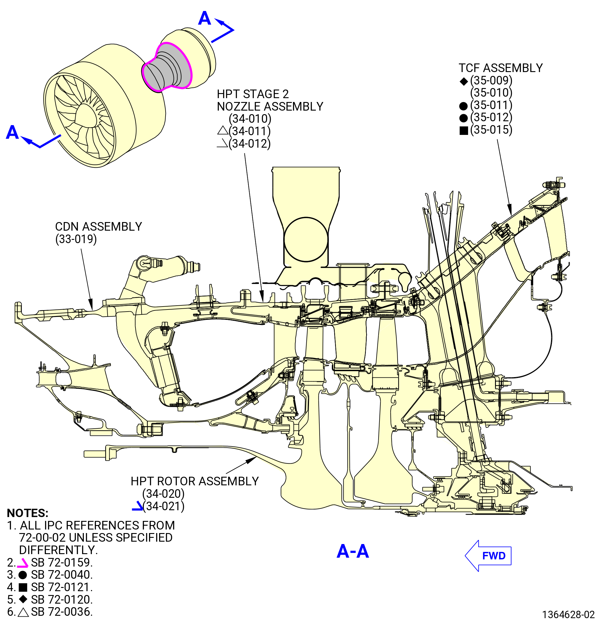
| A. | This procedure gives instructions to disassemble the high pressure turbine (HPT) module. Refer to Figure 501. |
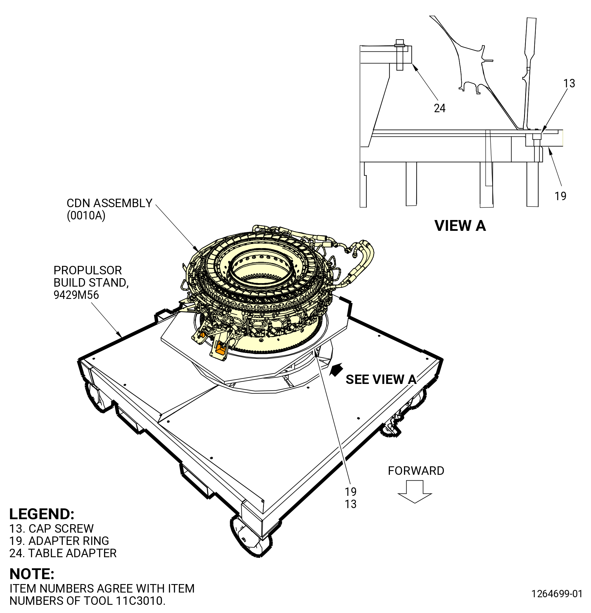
| B. | This procedure starts with the HPT module on the 11C3010 build-up fixture. Refer to Figure 502. |
| C. | Make sure that the engine assembly/sub-assembly/module has the correct support at all times to prevent injury to personnel or damage to engine parts. |
| D. | Before you do this procedure, read the assembly and disassembly techniques section. Refer to TASK 70-10-00-800-009 (ASSEMBLY AND DISASSEMBLY TECHNIQUES). |
| E. | Make sure that you follow the instructions carefully and know the special tools usage before you disassemble the HPT module. |
| F. | All directions are aft looking forward (ALF), unless specified differently. |
| G. | If an axisymmetric rotating part with a visible crack through the axial or radial thickness of the part feature is found during the disassembly procedure, then the mating Life Limited Part(s) (LLP) can be affected. The mating LLP must be considered not serviceable and not repairable. |
| NOTE: |
|
| NOTE: |
|
| 2 . | Tools, Equipment, and Materials. |
| NOTE: |
|
| A. | Tools and Equipment. |
| (1) | Special Tools. |
| (2) | Standard Tools and Equipment. |
|
| (3) | Locally Manufactured Tools. None. |
| B. | Consumable Materials. |
|
| C. | Referenced Procedures. |
|
| D. | Expendable Parts. |
|
| 3 . | Procedure. |
| Subtask 72-50-00-030-030 |
| A. | If installed, remove the 11C3025 strongback with 7C2015 lift fixture as follows. Refer to Figure 503. |
| (1) | Remove the capscrews (item 29) and washers (item 26) that attach the 11C3025 strongback to the turbine center frame assembly (TCF assembly) (35-009 , 72-00-02) (SIN 92500) or (35-010 , 72-00-02) (SIN 92500) or (35-011 , 72-00-02) (SIN 92500) or (35-012 , 72-00-02) (SIN 92500) or (35-015 , 72-00-02) (SIN 92500) aft flange. |
| (2) | Attach an overhead hoist to the lift fixture (item 2) of the 7C2015 lift fixture. |
| WARNING: |
|
| (3) | Lift the 7C2015 lift fixture to remove the 11C3025 strongback from the TCF aft flange. |
| (4) | Remove the shoulder detent pins (item 3) of the 7C2015 lift fixture to remove the lift fixture (item 2) from the 11C3025 strongback. |
| Subtask 72-50-00-030-031 |
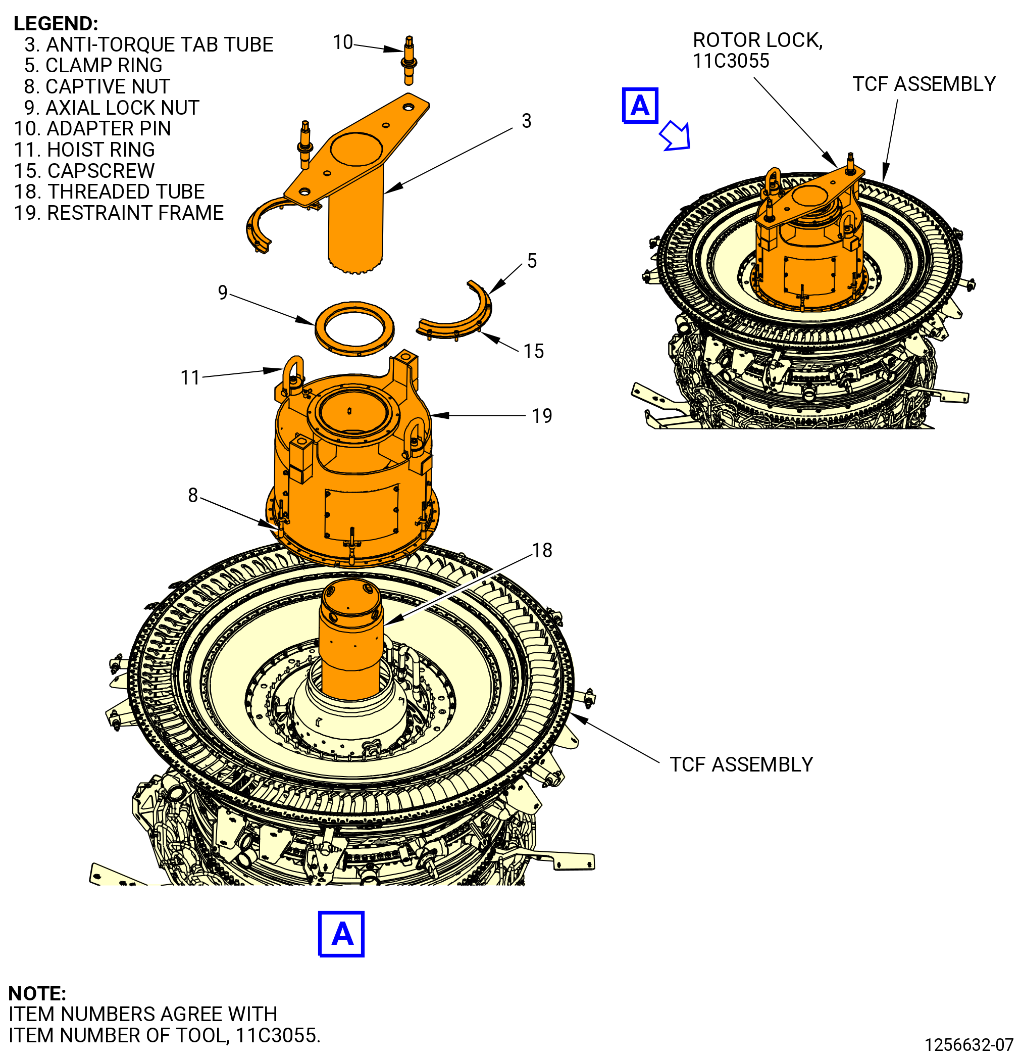
| B. | If installed, remove the 11C3055 rotor lock as follows. Refer to Figure 504. |
| (1) | Remove the capscrews (item 15) and the two halves of the clamp ring (item 5). |
| (2) | Remove the adapter pins (item 10). |
| (3) | Use a spanner wrench to loosen the axial lock nut (item 9). |
| (4) | Turn the anti-torque tab tube (item 3) until the forward tabs disengage from the slots in the HPT rotor shaft. Remove the anti-torque tab tube (item 3) from the threaded tube (item 18). |
| (5) | Loosen the captive nuts (item 8) that attach the restraint frame (item 19) to the TCF assembly. |
| (6) | Attach a lift sling to the two hoist rings (item 11) on the aft side of the restraint frame (item 19). |
| WARNING: |
|
| (7) | Lift the restraint frame (item 19) to remove it from the TCF assembly. |
| (8) | Turn the threaded tube (item 18) to remove it from the threads of the HPT rotor shaft. Use a leverage bar through the 1.00 inch (25.4 mm) diameter holes at the aft end of the threaded tube (item 18). |
| (9) | Remove the threaded tube (item 18). |
| Subtask 72-50-00-030-032 |
| C. | Make sure that the No. 4 bearing rotating seal (01408) is removed. Refer to TASK 72-00-02-030-804 (72-00-02, DISASSEMBLY 004). |
| Subtask 72-50-00-030-033 |
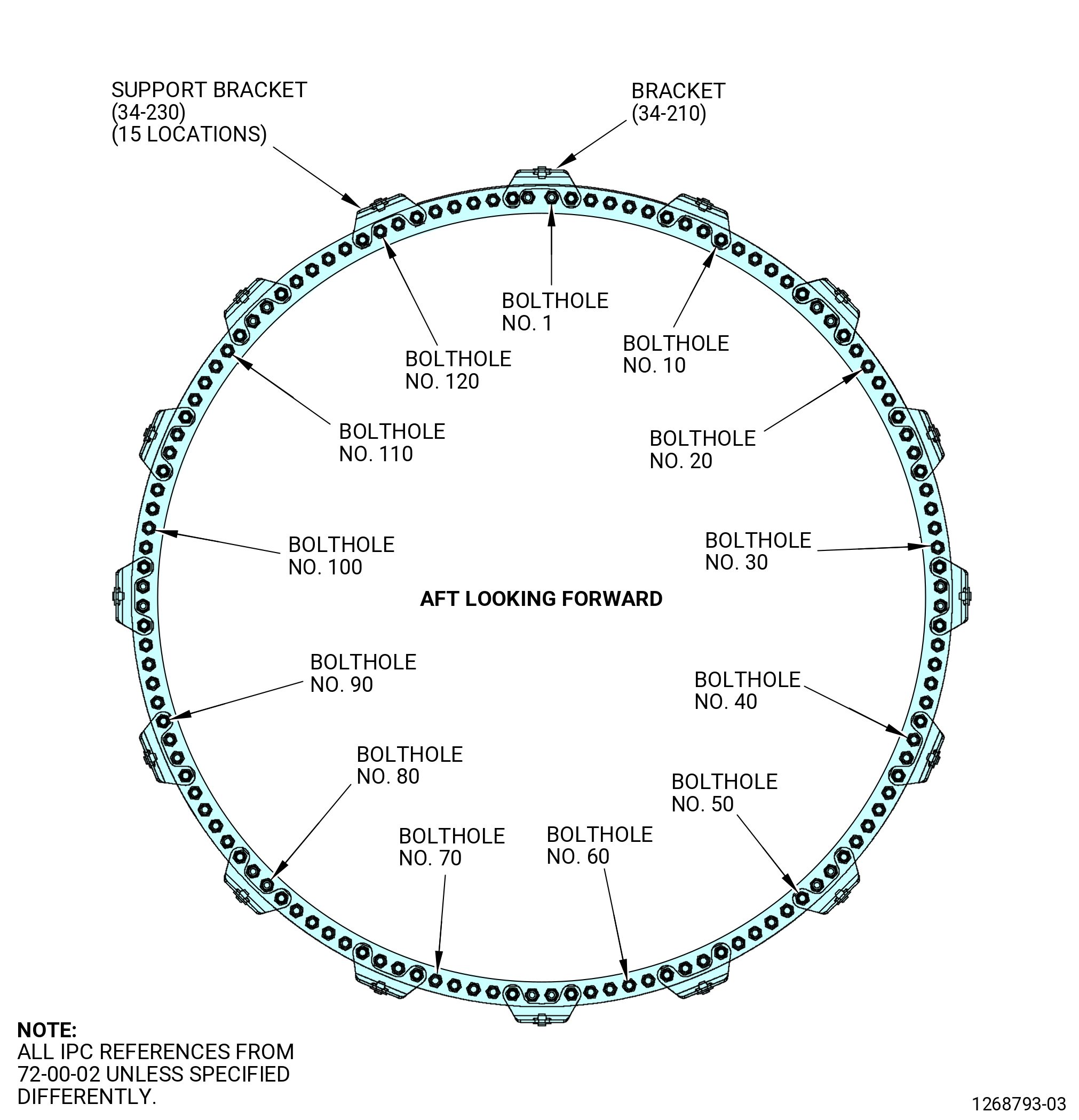
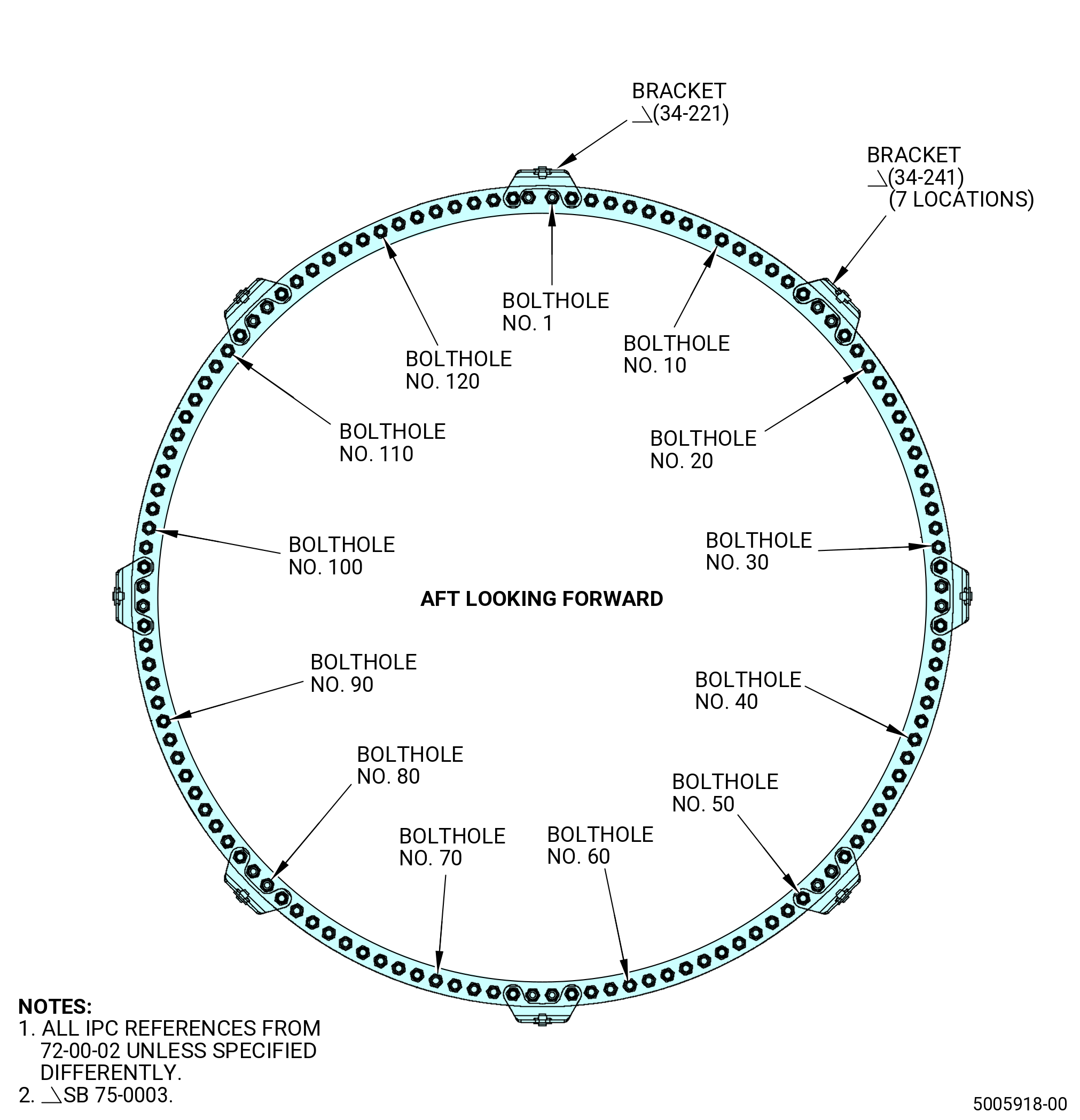
| D. | Remove the flange hardware and brackets from each bolthole location at the HPT stage 2 nozzle/TCF flange. Refer to Figure 505 and Figure 505A. |
|
|
| Subtask 72-50-00-490-001 |
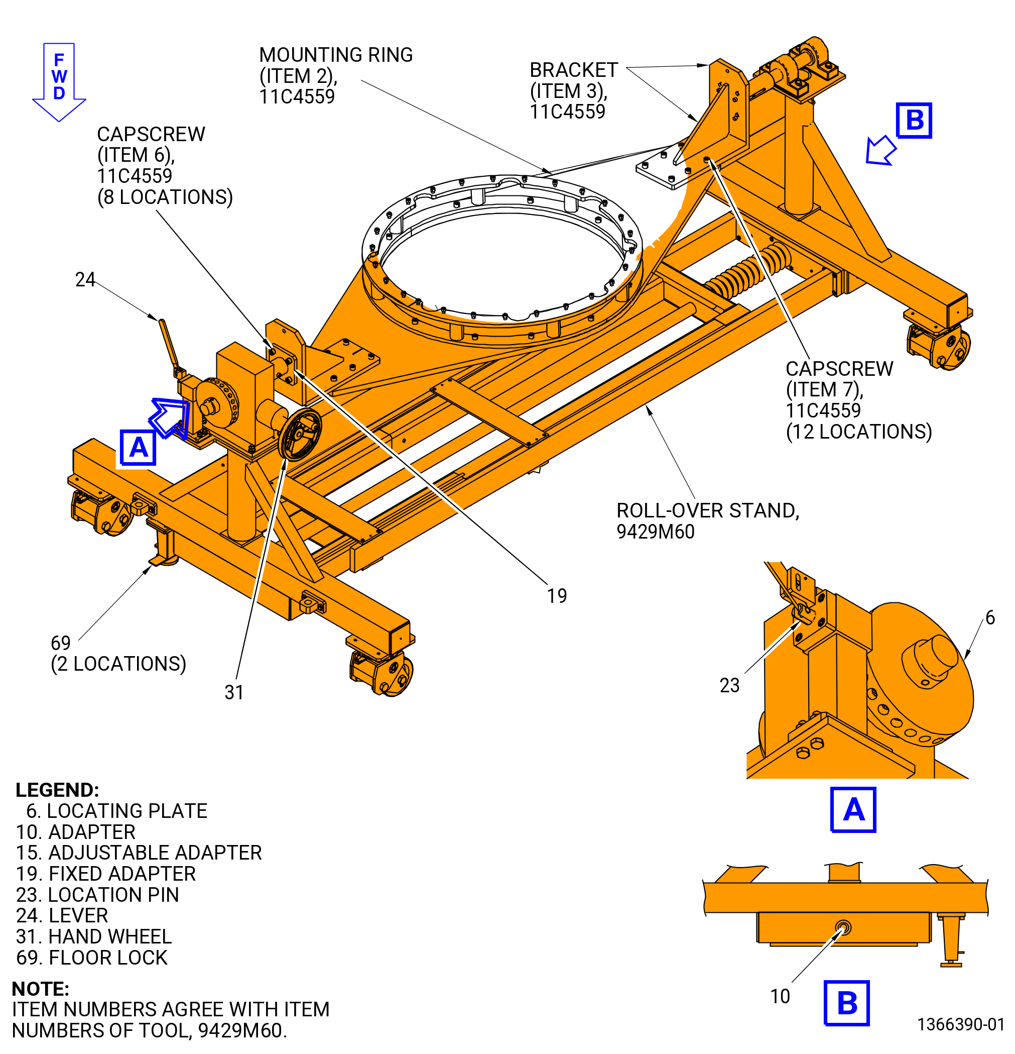
| E. | Install the 11C4559 bracket set on the 9429M60 roll-over stand as follows. Refer to Figure 506. |
| CAUTION: |
|
| (1) | Lower the floor locks (item 69) of the 9429M60 roll-over stand until they touch the floor. The floor locks must stay in contact with the floor to prevent movement of the roll-over stand. |
| (2) | Push the lever (item 24) to unlock the hand wheel (item 31). |
| (3) | Turn the hand wheel (item 31) until the locating plate (item 6) is in the vertical position. |
| CAUTION: |
|
| (4) | Release the lever (item 24) to engage the locating pin (item 23) to lock the hand wheel (item 31). |
| (5) | Turn the adapter (item 10) of the 9429M60 roll-over stand to adjust the length to install the 11C4559 bracket set. |
| (6) | Attach the bracket (item 3) of the 11C4559 bracket set to the fixed adapter (item 19) of the 9429M60 roll-over stand as follows:. |
| (a) | Position the horizontal surface of the bracket up. |
| (b) | Secure the bracket (item 3) of the 11C4559 bracket set to the 9429M60 roll-over stand with capscrews (item 6) of the 11C4559 bracket set. |
| (c) | Torque the capscrews (item 6) to 106-124 lb in. (12-14 N.m). |
| (7) | Attach the bracket (item 3) of the 11C4559 bracket set to the adjustable adapter (item 15) of the 9429M60 roll-over stand as follows: |
| (a) | Secure the bracket (item 3) of the 11C4559 bracket set to the 9429M60 roll-over stand with capscrews (item 6) of the 11C4559 bracket set. |
| (b) | Torque the capscrews (item 6) to 106-124 lb in. (12-14 N.m). |
| (8) | Attach the mounting ring (item 2) of the 11C4559 bracket set to the bracket (item 3) as follows: |
| (a) | Attach a sling to the mounting ring (item 2) on an overhead hoist. |
| WARNING: |
|
| (b) | Lift the mounting ring and position on the bracket (item 3) with engraved markings (forward side) up. |
| (c) | Secure the mounting ring (item 2) to the bracket (item 3) with capscrews (item 7). |
| (d) | Torque the capscrews (item 7) to 106-124 lb in. (12-14 N.m). |
| (9) | Push the lever (item 24) of the 9429M60 roll-over stand to unlock the hand wheel (item 31). |
| (10) | Turn the hand wheel (item 31) to put the mounting ring (item 2) of the 11C4559 bracket set scribed marks (forward side) down. |
| (11) | Release the lever (item 24) of the 9429M60 roll-over stand to engage the locating plate (item 6) to lock the hand wheel (item 31). |
| NOTE: |
|
| (12) | Put a mark on the aft face of the mounting ring (item 2) of the 11C4559 bracket set that is aligned with the TOP VERT mark on the forward face of the mounting ring. |
| Subtask 72-50-00-030-034 |
| F. | Remove the TCF assembly from the aft end of the HPT stage 2 nozzle assembly and the HPT rotor assembly (34-020 , 72-00-02) (SIN 15000) or (34-021 , 72-00-02) (SIN 15000) as follows: |
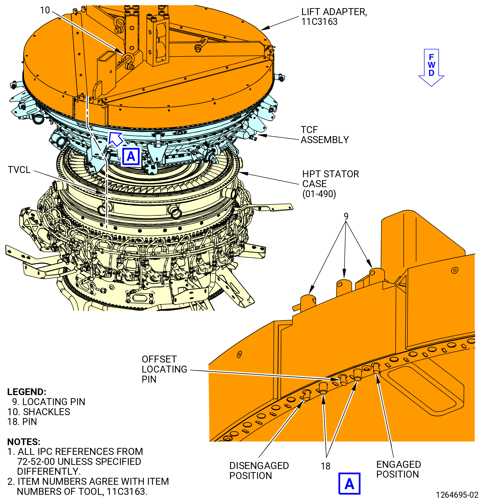
| (1) | Attach the 11C3159 guide and the 11C3163 lift adapter as follows. Refer to Figure 507 and Figure 508. |
| WARNING: |
|
| (a) | Use an overhead hoist to lift the 11C3159 guide and align it with the aft end of the HPT rotor shaft. |
| (b) | Turn the 11C3159 guide to engage the threads on the HPT rotor shaft. |
| (c) | Use a breaker bar through the 0.515 inch (13.08 mm) diameter holes to tighten the 11C3159 guide . |
| (d) | Attach the three-legged sling to the three shackles (item 10) of the 11C3163 lift adapter. |
| (e) | Turn the nine locating pins (item 9) so the pin points outward to the disengaged position. |
| (f) | Lift the 11C3163 lift adapter with an overhead hoist and put it above the TCF assembly with the horizontal lift tube at the top vertical centerline (TVCL). |
| NOTE: |
|
| (g) | Lower the lift adapter on the TCF assembly. Align the pins (item 18) and the locating pins (item 9) to the flange boltholes. Make sure that the offset bolthole and offset locating pin (9) are aligned. |
| (h) | Rotate the nine locating pins (item 9) so the pin points inward to the engaged position. |
| (2) | Lift the TCF assembly from the HPT stage 2 nozzle assembly. If necessary, use a rubber mallet to disengage the TCF assembly. Use care to make sure that the HPT stage 2 shroud aft retainer remains installed on the HPT stage 2 shrouds. |
| Subtask 72-50-00-030-069 |
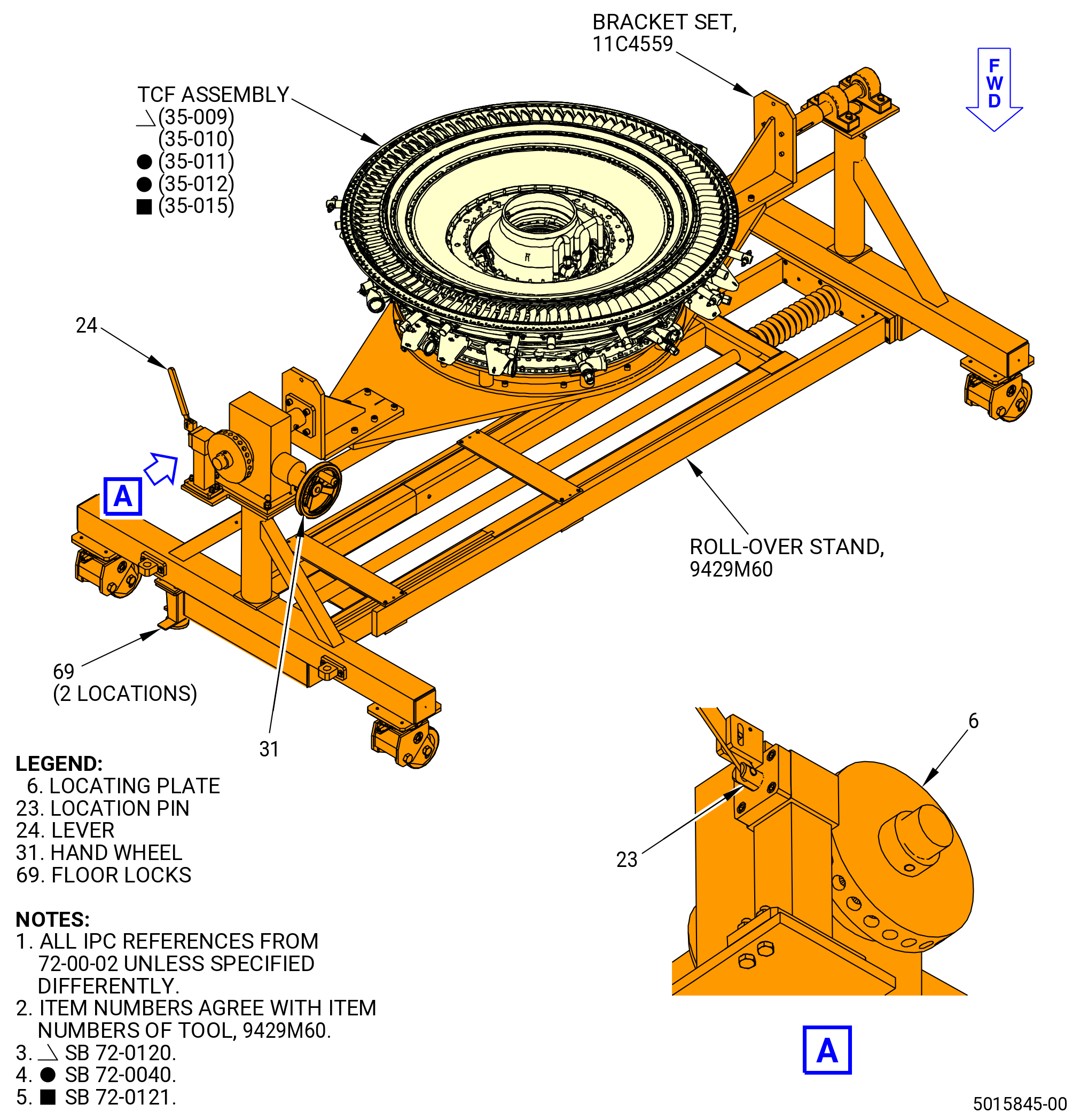
| G. | Install the TCF assembly (35-009 , 72-00-02) (SIN 92500) or (35-010 , 72-00-02) (SIN 92500) or (35-011 , 72-00-02) (SIN 92500) or (35-012 , 72-00-02) (SIN 92500) or (35-015 , 72-00-02) (SIN 92500) in the vertical position, forward end down, on the aft side of 11C4559 bracket set installed on the 9429M60 roll-over stand. Refer to Figure 509 and do as follows: |
| (1) | Lift the TCF assembly, forward flange down, and put the TCF assembly on the spacer (item 4) of the 11C4559 bracket set. |
| (2) | Align the top of the TCF assembly with the TOP VERT mark on the mounting ring (item 2). |
| (3) | Put the TCF assembly on the spacer (item 4) and make sure that the boltholes are aligned. |
| (4) | Install the cap screws (item 8) and plain nuts (item 9) and tighten the nuts to secure the TCF assembly to the spacer (item 4). |
| Subtask 72-50-00-000-002 |
| H. | Remove the 11C3159 guide and the 11C3163 lift adapter from the TCF assembly (35-009 , 72-00-02) (SIN 92500) or (35-010 , 72-00-02) (SIN 92500) or (35-011 , 72-00-02) (SIN 92500) or (35-012 , 72-00-02) (SIN 92500) or (35-015 , 72-00-02) (SIN 92500). Refer to Figure 507, Figure 508, and do as follows: |
| (1) | Remove the six 0.375-16 UNC-3B bolts and six pins (item 18) that attach the 11C3163 lift adapter to the TCF assembly. |
| WARNING: |
|
| (2) | Lift the 11C3163 lift adapter from the TCF assembly with a three-legged sling and overhead hoist. |
| (3) | Put a breaker bar through the 0.515 inch (13.08 mm) diameter holes to loosen the 11C3159 guide . |
| (4) | Turn the 11C3159 guide to disengage the threads on the HPT rotor shaft. |
| (5) | Use an overhead hoist to lift the 11C3159 guide from the aft end of the HPT rotor shaft. |
| Subtask 72-50-00-030-042 |
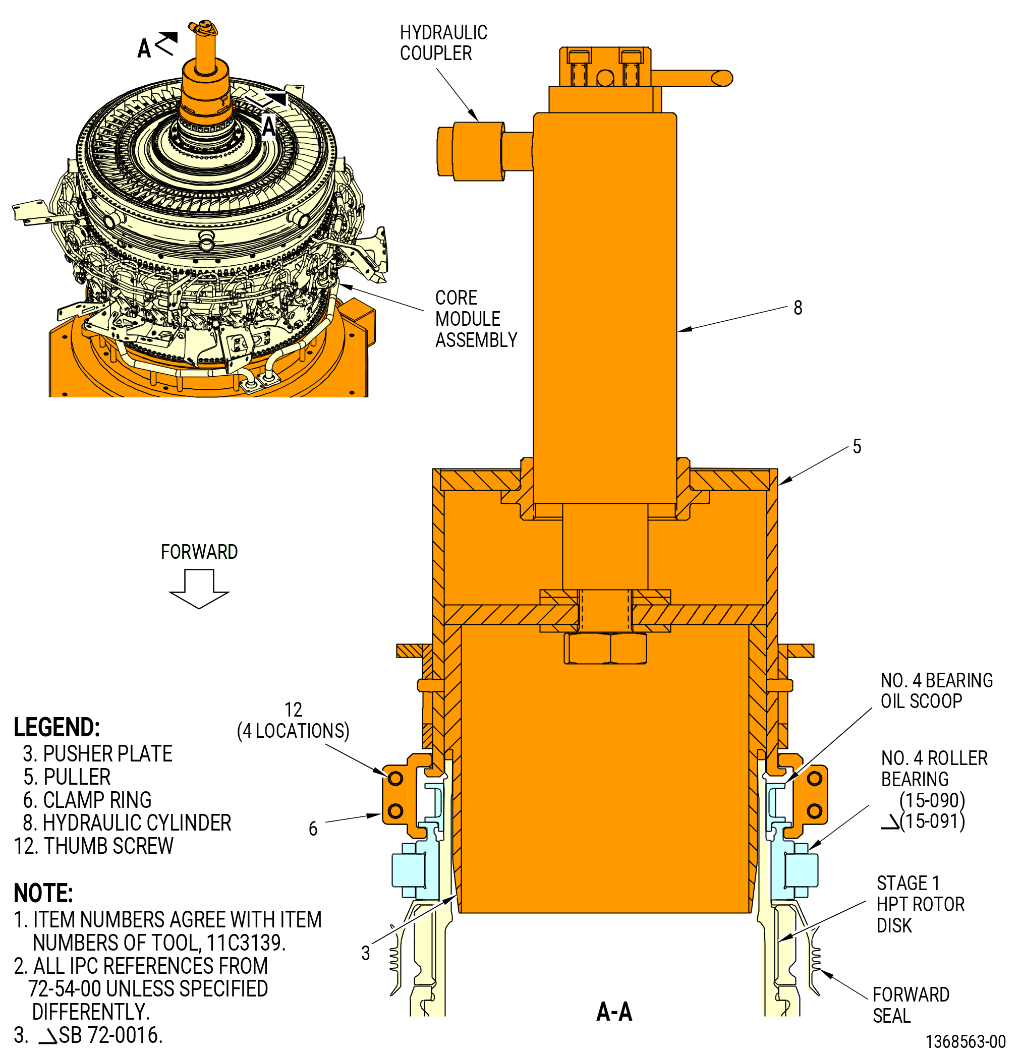
| I. | Remove the No. 4 bearing radial oil scoop (oil scoop) and the inner race of the No. 4 cylindrical roller bearing (No. 4 roller bearing) (15-090 , 72-54-00) (SIN 01400) or (15-091 , 72-54-00) (SIN 01400) with the 11C3139 puller as follows. Refer to Figure 510. |
| (1) | Put the 11C3139 puller on the aft shaft of the HPT rotor assembly (34-020 , 72-00-02) (SIN 15000) or (34-021 , 72-00-02) (SIN 15000) with the pusher plate (item 3) in the shaft and the puller (item 5) against the oil scoop. |
| (2) | Put the clamp ring (item 6) halves in the groove of the inner race and the puller (item 5). |
| (3) | Attach the clamp ring (item 6) halves together with the thumb screws (item 12). |
| (4) | Attach a hydraulic pump to the hydraulic cylinder (item 8). |
| WARNING: |
|
| (5) | Operate the hydraulic pump to disengage the oil scoop and the inner race. |
| (6) | Release the pressure on the hydraulic pump. |
| (7) | Remove the hydraulic pump and the 11C3139 puller. |
| (8) | Remove the oil scoop and the inner race. |
| (9) | Put the inner race in a bag and attach a tag with the serial number. |
| NOTE: |
|
| Subtask 72-50-00-030-044 |
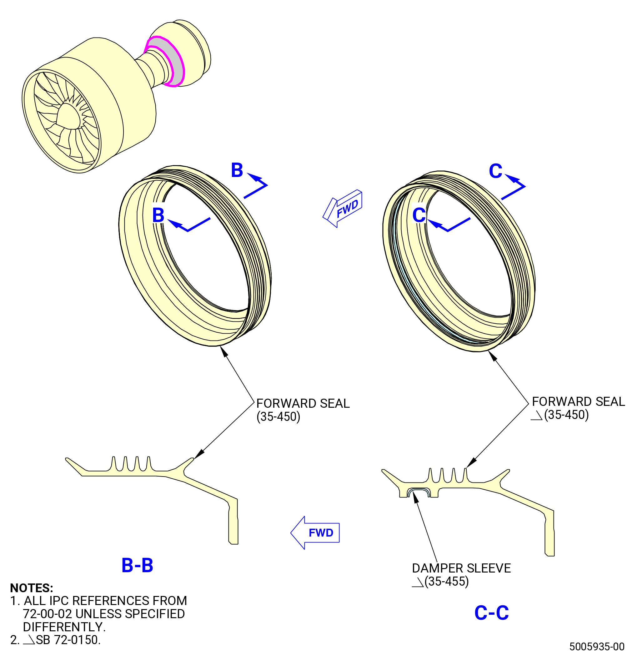
| J. | Remove the HPT inner sump seal (forward seal). |
| Subtask 72-50-00-030-084 |
| * * * SB 72-0150( Introduction of the Damper Sleeve and a New Forward Seal ) |
| (1) | Remove the damper sleeve (35-455 , 72-00-02) (SIN 01492) from the inner groove of the forward seal (35-450 , 72-00-02) (SIN 01401). Discard the damper sleeve (35-455 , 72-00-02) (SIN 01492). |
| NOTE: |
|
| * * * END SB 72-0150 |
| Subtask 72-50-00-030-045 |
| K. | Remove the stage 1 nozzle borescope plug assembly from the HPT case at the 3:00 o'clock position, ALF. |
| Subtask 72-50-00-030-046 |
| L. | Remove the HPT rotor stage 2 blade retainer (blade retainer) and the aft retainer ring as follows. Refer to Figure 511 and Figure 512. |
| (1) | Disengage the blade retainer with the 11C3017 install/remove fixture as follows: |
| CAUTION: |
|
| (a) | Install the push-pull plate (item 4) of the 11C3017 install/remove fixture on the stage 1 HPT rotor disk. Turn the push-pull plate (item 4) clockwise (CW) to install. Tighten the push-pull plate (item 4) hand-tight. |
| (b) | Install the base (item 17) of the 11C3017 install/remove fixture on the aft stage 2 blade retainer (34-270 , 72-00-02) (SIN 150B5) or (34-271 , 72-00-02) (SIN 150B5) as follows: |
| 1 | Attach an overhead hoist to the hoist rings (item 8). |
| 2 | Align the cutout in the base (item 17) with the split-line gap of the aft stage 2 blade retainer. |
| NOTE: |
|
| 3 | Lower the base (item 17) on the aft stage 2 blade retainer. |
| NOTE: |
|
| (c) | Install the hydraulic cylinder (item 7) on the shaft of the push-pull plate (item 4). |
| (d) | Attach the nut (item 14) to the shaft on the push-pull plate (item 4). |
| (e) | Connect the hydraulic pump to the hydraulic cylinder (item 7) of the 11C3017 install/remove fixture. |
| (f) | Put the valve on the hydraulic pump in the PUSH position. |
| (g) | Operate the hydraulic pump three to five full strokes to prevent free movement of the 11C3017 install/remove fixture. |
| (h) | Make sure that the stage 2 ring (item 16) of the 11C3017 install/remove fixture is aligned with the aft stage 2 blade retainer. |
| CAUTION: |
|
| (i) | Apply a maximum pressure of 10,000 psig (68950 kPa gage) to deflect the aft stage 2 blade retainer. When you apply the pressure, the 11C3017 install/remove fixture will apply downward pressure on the aft stage 2 blade retainer. Apply sufficient pressure to permit free movement of the aft retainer ring. |
| (j) | Compress the aft retainer ring (150B7) as follows: |
| 1 | Install the 9429M68 retaining ring tool set in the holes on the ends on the aft retainer ring. |
| 2 | Adjust the tool set to move the aft retainer ring in (compressed position) below the hook of the stage 2 disk. |
| NOTE: |
|
| 3 | Compress the aft retainer ring completely below the hook and install a clip (item 19) of the 11C3017 install/remove fixture around each end of the aft retainer ring end gap. |
| NOTE: |
|
| 4 | Install the remaining clips (item 19) around the aft retainer ring approximately 30 degrees apart. |
| (k) | Remove the 9429M68 retaining ring tool set. |
| (l) | Put the valve on the hydraulic pump in the PULL position. |
| (m) | Operate the hydraulic pump three to five full strokes to release the pressure and lift the 11C3017 install/remove fixture from the stage 2 blade retainer. |
| (n) | Disconnect the hydraulic pump from the hydraulic cylinder (item 7). |
| (o) | Remove the nut (item 14) from the shaft on the push-pull plate (item 4). |
| (p) | Remove the hydraulic cylinder (item 7) from the shaft on the push-pull plate (item 4). |
| (q) | Attach an overhead hoist to the hoist rings (item 8) and remove the 11C3017 install/remove fixture. |
| CAUTION: |
|
| (r) | Carefully remove the push-pull plate (item 4) from the aft end of the stage 1 HPT rotor disk. Turn the push-pull plate (item 4) counterclockwise (CCW) to remove it. |
| (2) | Install the 11C3126 chill fixture on the aft stage 2 blade retainer as follows. Refer to Figure 513. |
| (a) | Carefully put the 11C3126 chill fixture on the aft stage 2 blade retainer. |
| WARNING: |
|
| (b) | Put dry ice in the 11C3126 chill fixture. |
| (c) | Chill the aft stage 2 blade retainer for 10-20 minutes. |
| (3) | Remove the 11C3126 chill fixture from the aft stage 2 blade retainer and quickly remove the aft stage 2 blade retainer. |
| (4) | Remove the clips (item 19) of the 11C3017 install/remove fixture from the aft retainer ring. Refer to Figure 511. |
| (5) | Remove the aft retainer ring. Use the 9429M68 retaining ring tool set to expand the aft retainer ring as necessary. Refer to Figure 513. |
| Subtask 72-50-00-030-078 |
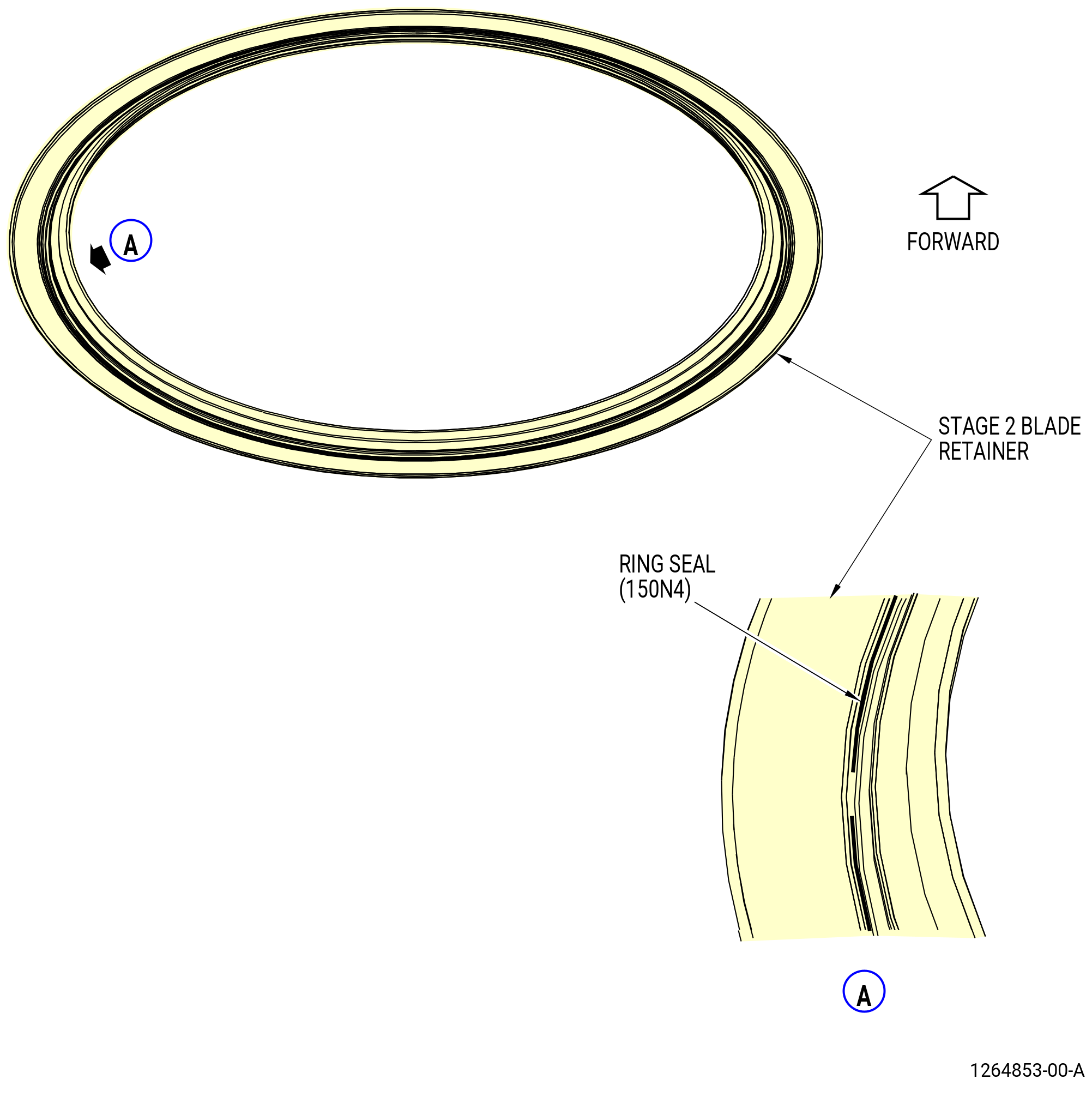
| M. | Remove and discard the ring seal (34-290 , 72-00-02) (SIN 150N4) from the blade retainer. Refer to Figure 514. |
| Subtask 72-50-00-030-049 |
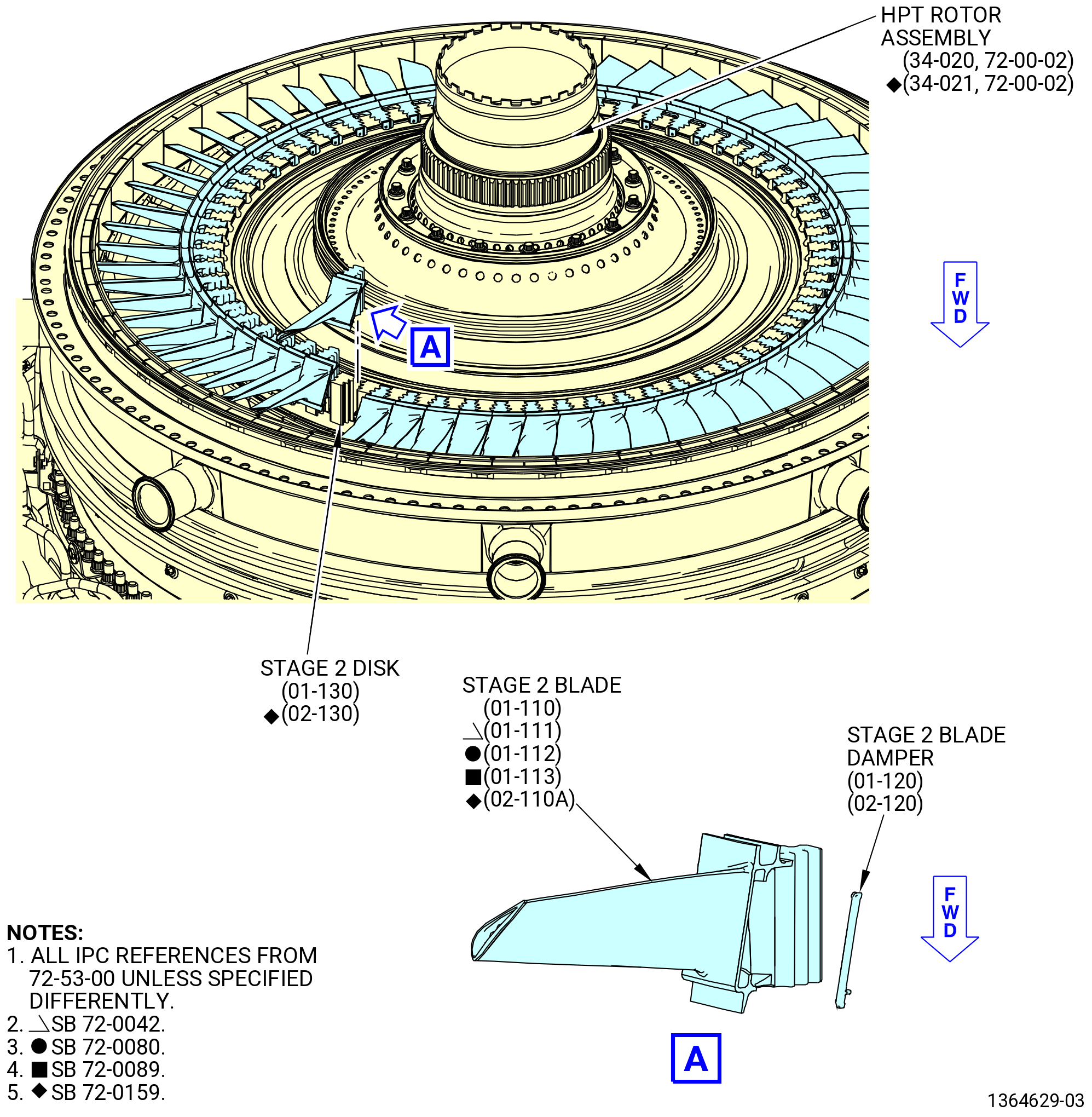
| N. | Remove the HPT rotor stage 2 blades (stage 2 blades) (01-110 , 72-53-00) (SIN 150B0) or (01-111 , 72-53-00) (SIN 150B0) or (01-112 , 72-53-00) (SIN 150B0) or (01-113 , 72-53-00) (SIN 150B0) or (02-110A , 72-53-00) (SIN 150B0) from the stage 2 disk. Refer to Figure 515 and do as follows: |
| (1) | If necessary, use the C05-003 pen to put a mark on each dovetail slot of the stage 2 disk and each dovetail of the stage 2 blades in relation to the blade position in the stage 2 disk. Begin the marks with the 1-1 slot (marked on the disk post) and move CW, ALF. |
| NOTE: |
|
| (2) | Remove the stage 2 blades and dampers (01-120 , 72-53-00) (SIN 150B8) or (02-120 , 72-53-00) (SIN 150B8) from the stage 2 disk as follows: |
| (a) | Move a blade axially aft a small distance until you can move the adjacent blade axially aft. |
| CAUTION: |
|
| (b) | Continue this procedure until you can remove a blade and a stage 2 damper. |
| NOTE: |
|
| (c) | Remove the remaining stage 2 blades and dampers. |
| (d) | Put all the stage 2 blades in the 11C3015 blade container, airfoils facing down. |
| (3) | Discard the stage 2 blade dampers (01-120 , 72-53-00) (SIN 150B8) or (02-120 , 72-53-00) (SIN 150B8). |
| Subtask 72-50-00-030-081 |
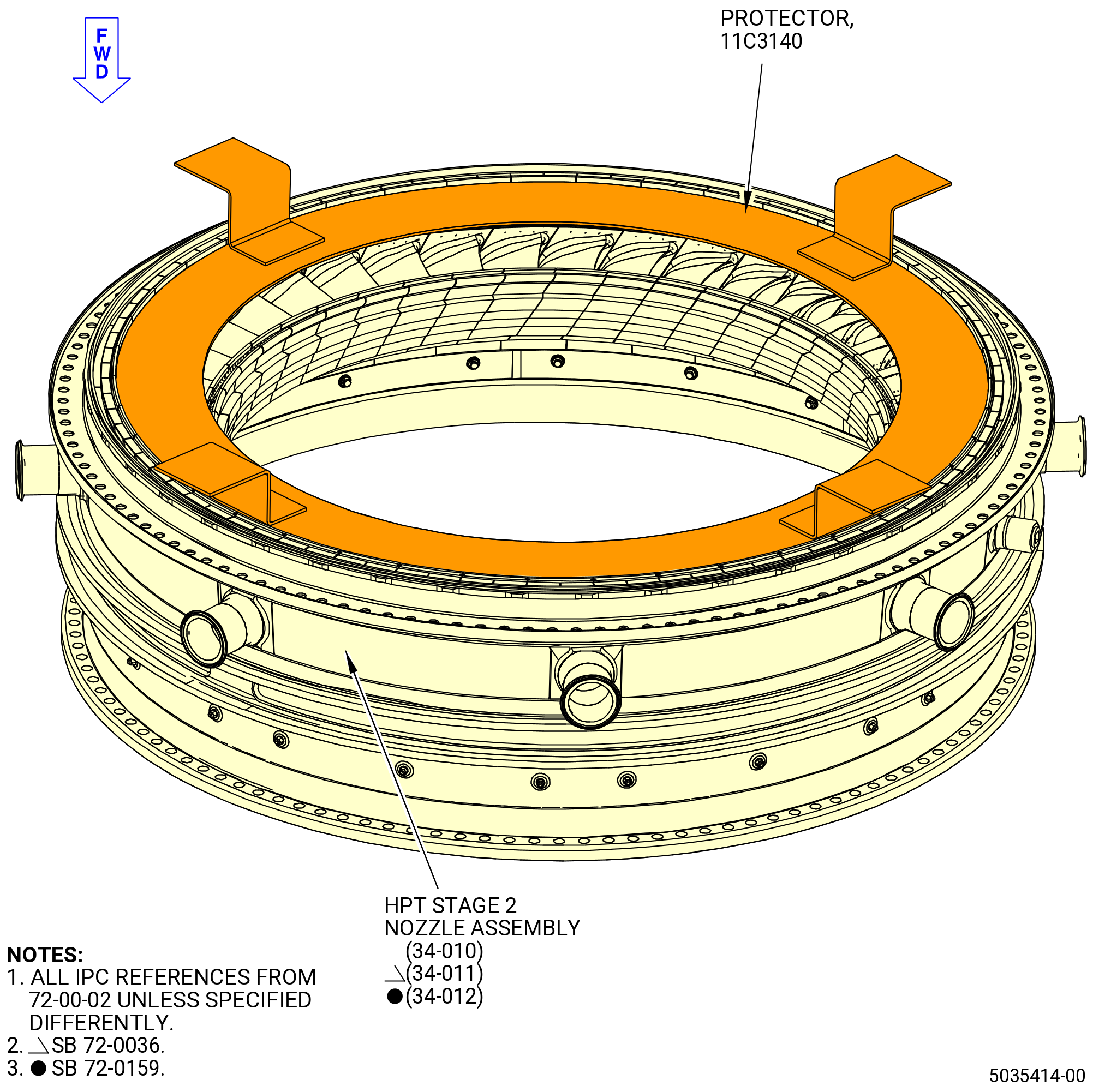
| O. | Put the 11C3140 protector above the HPT stage 2 nozzles. Refer to Figure 516. |
| Subtask 72-50-00-030-086 |
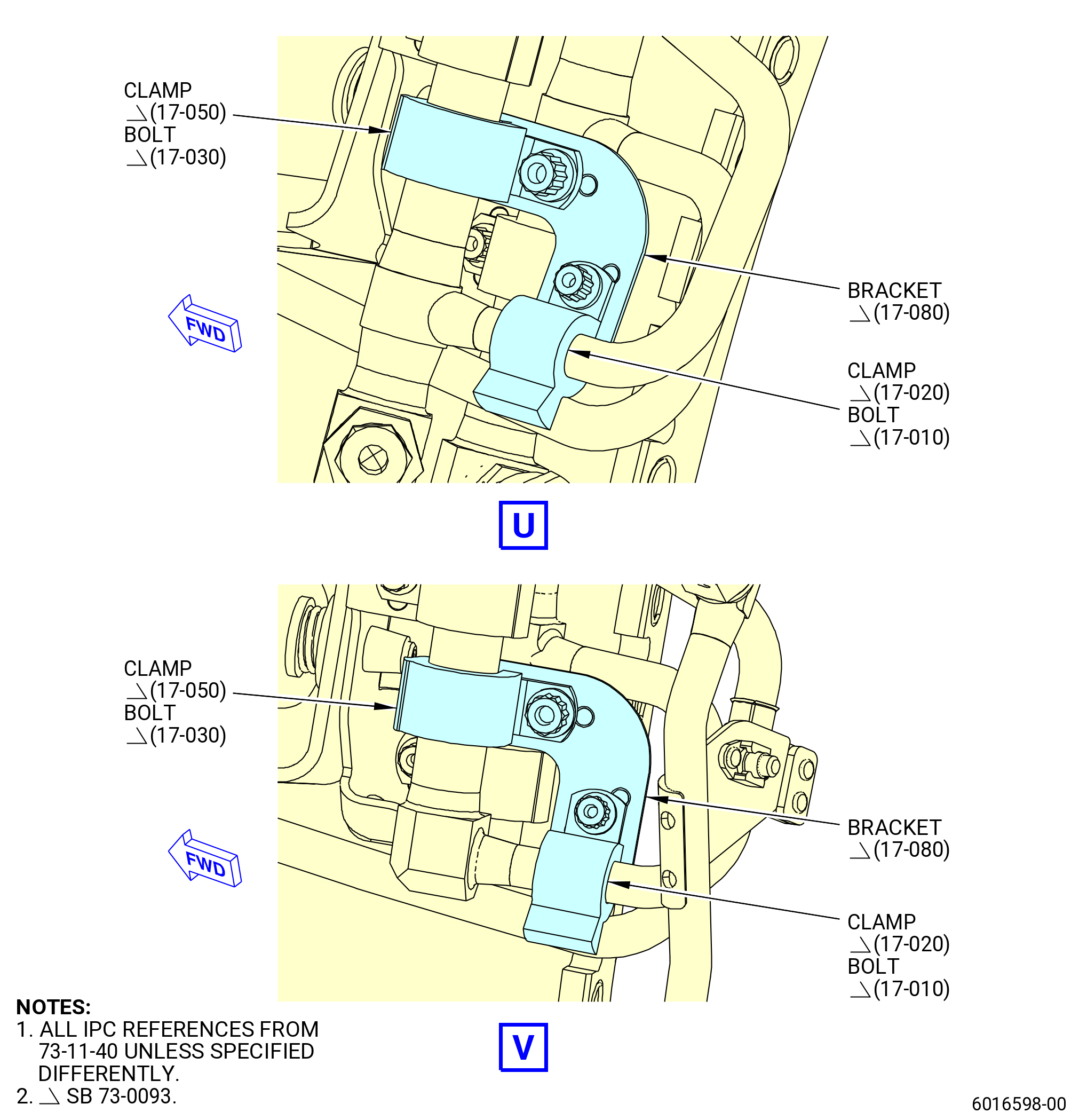
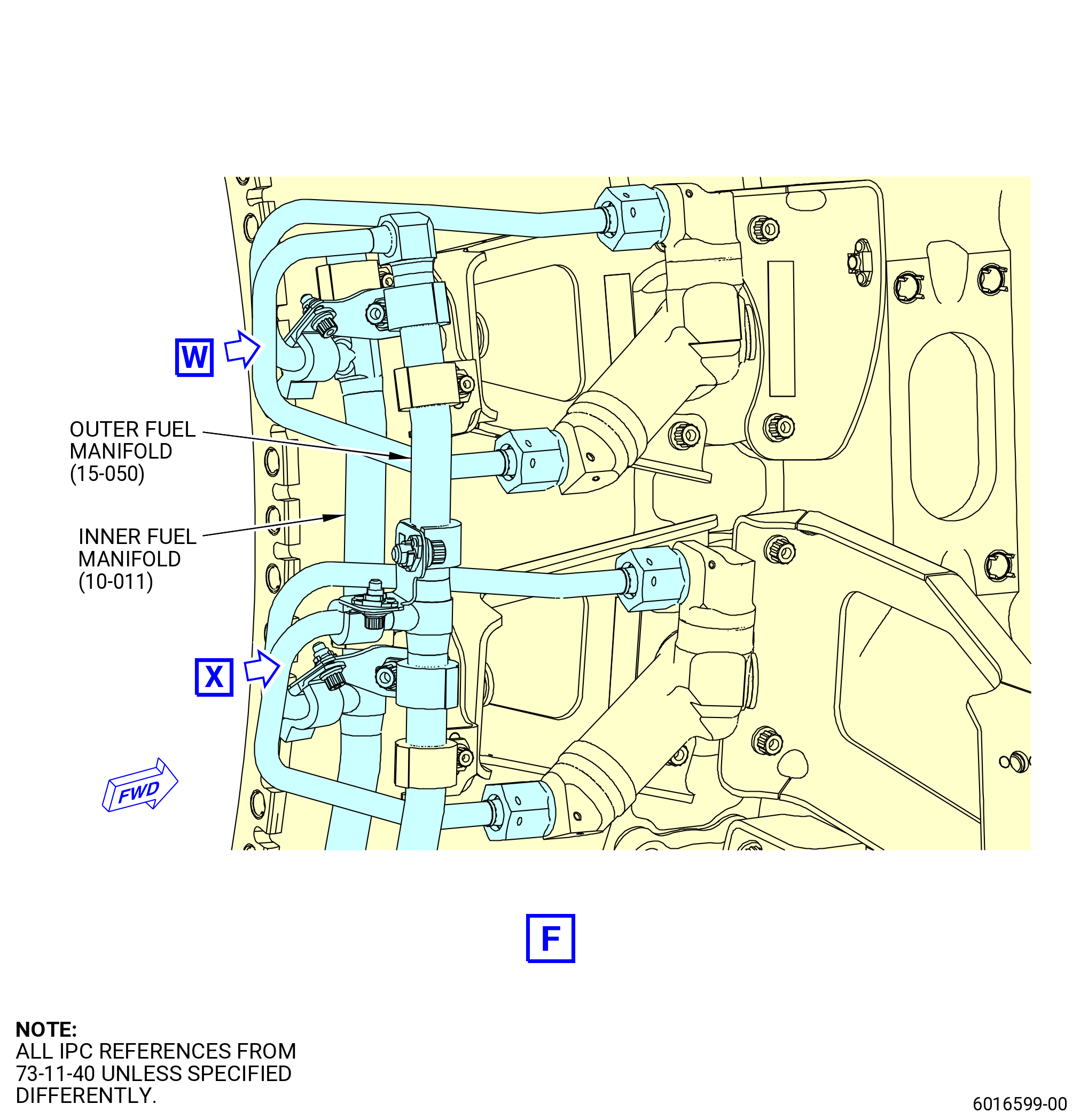
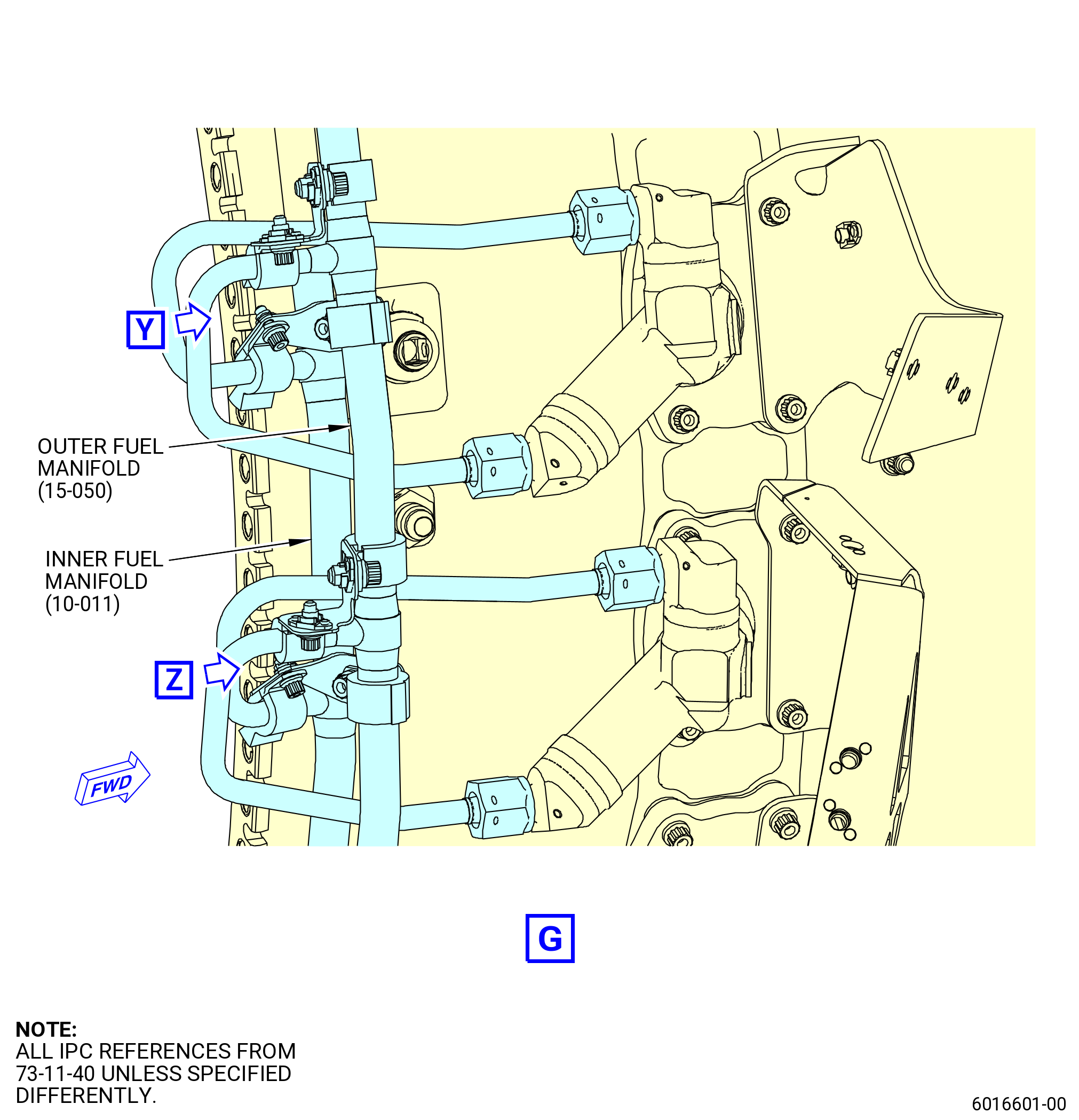
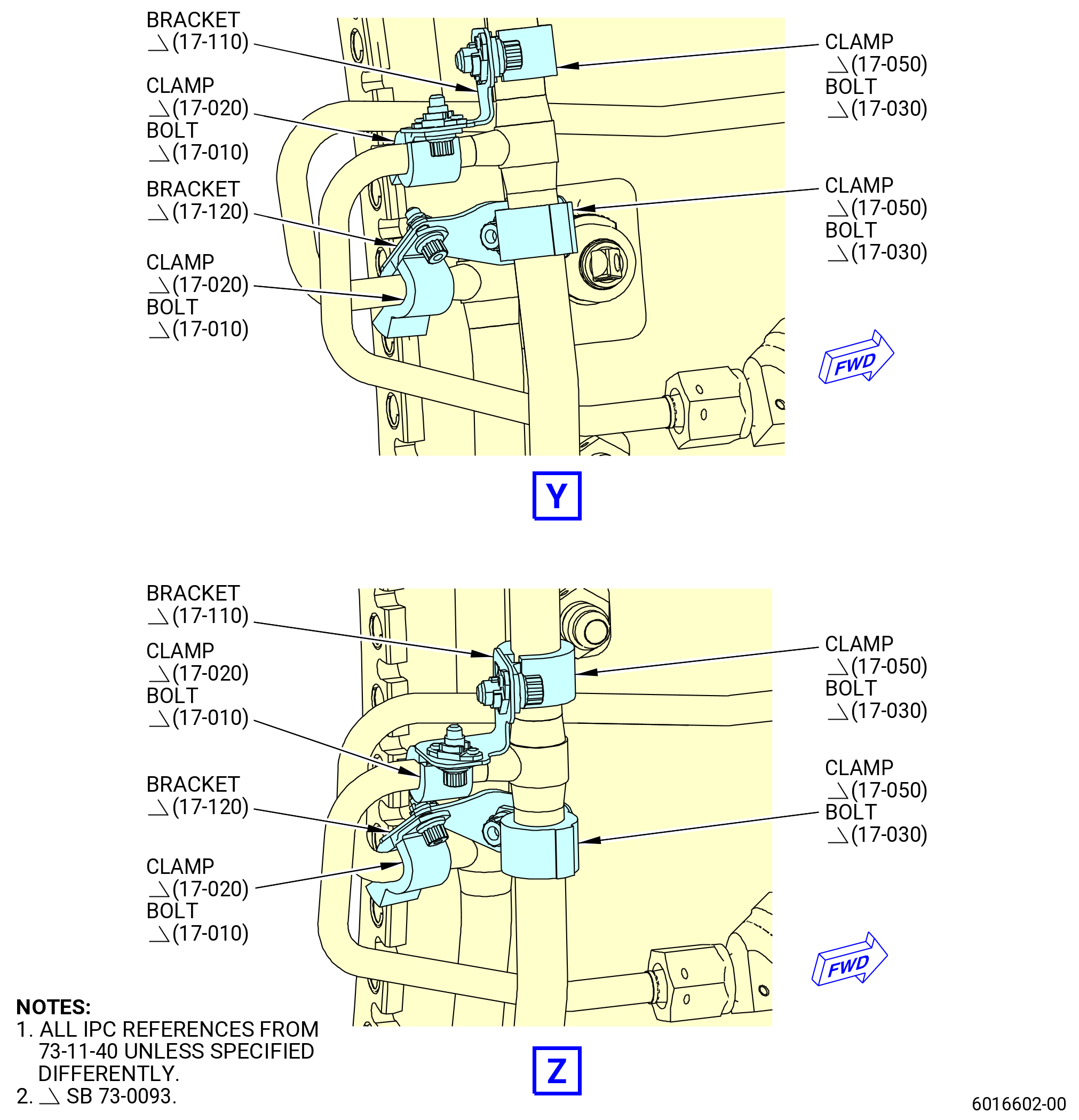
| * * * SB 73-0093( Engines with New Pigtail Brackets Configuration ) |
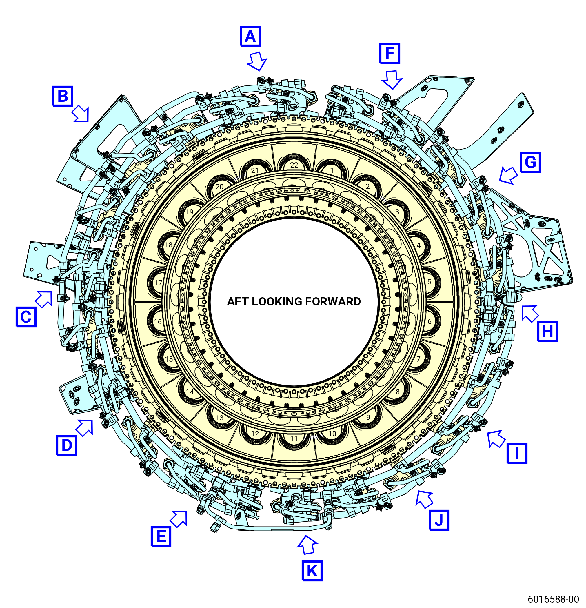
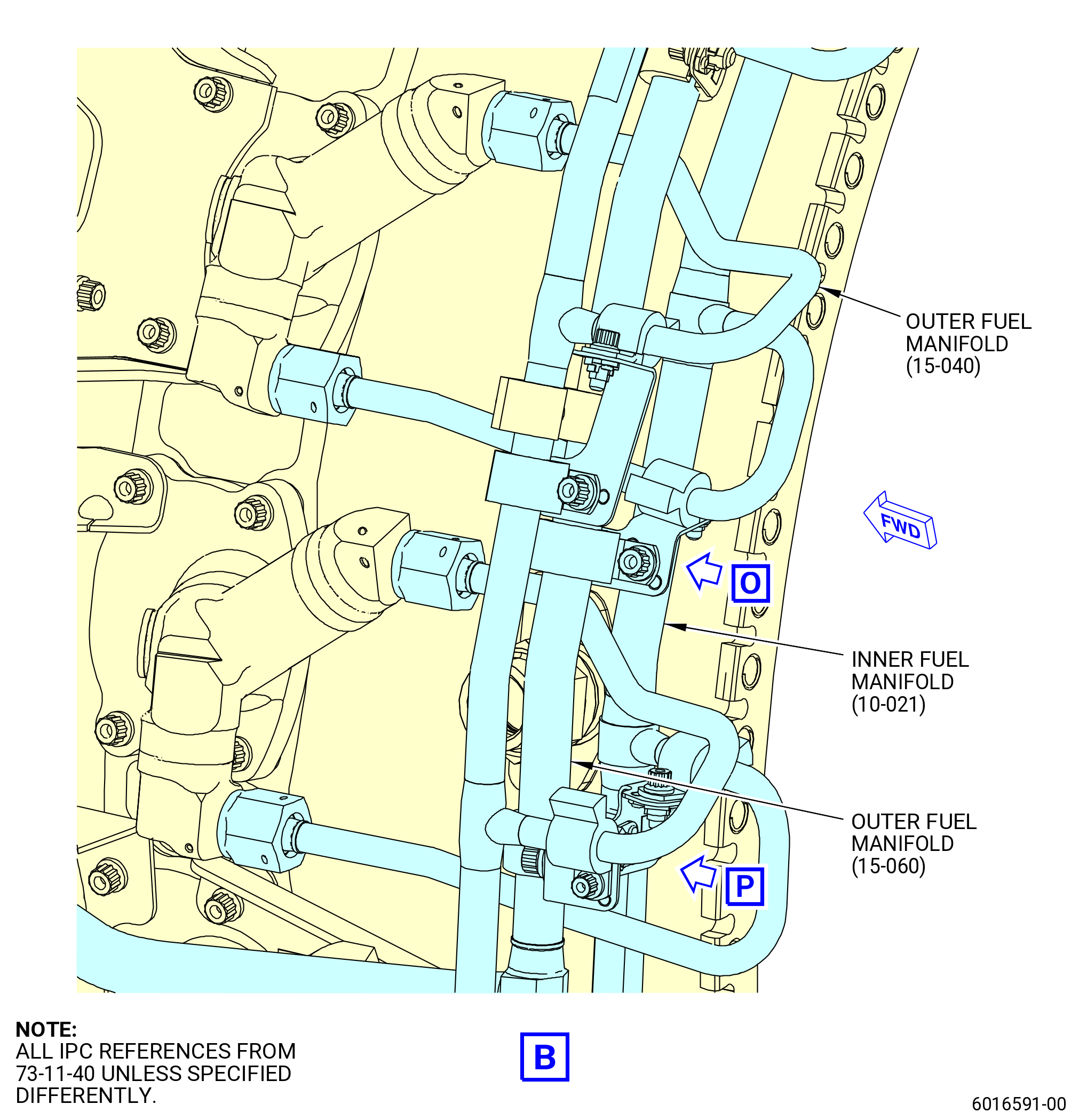
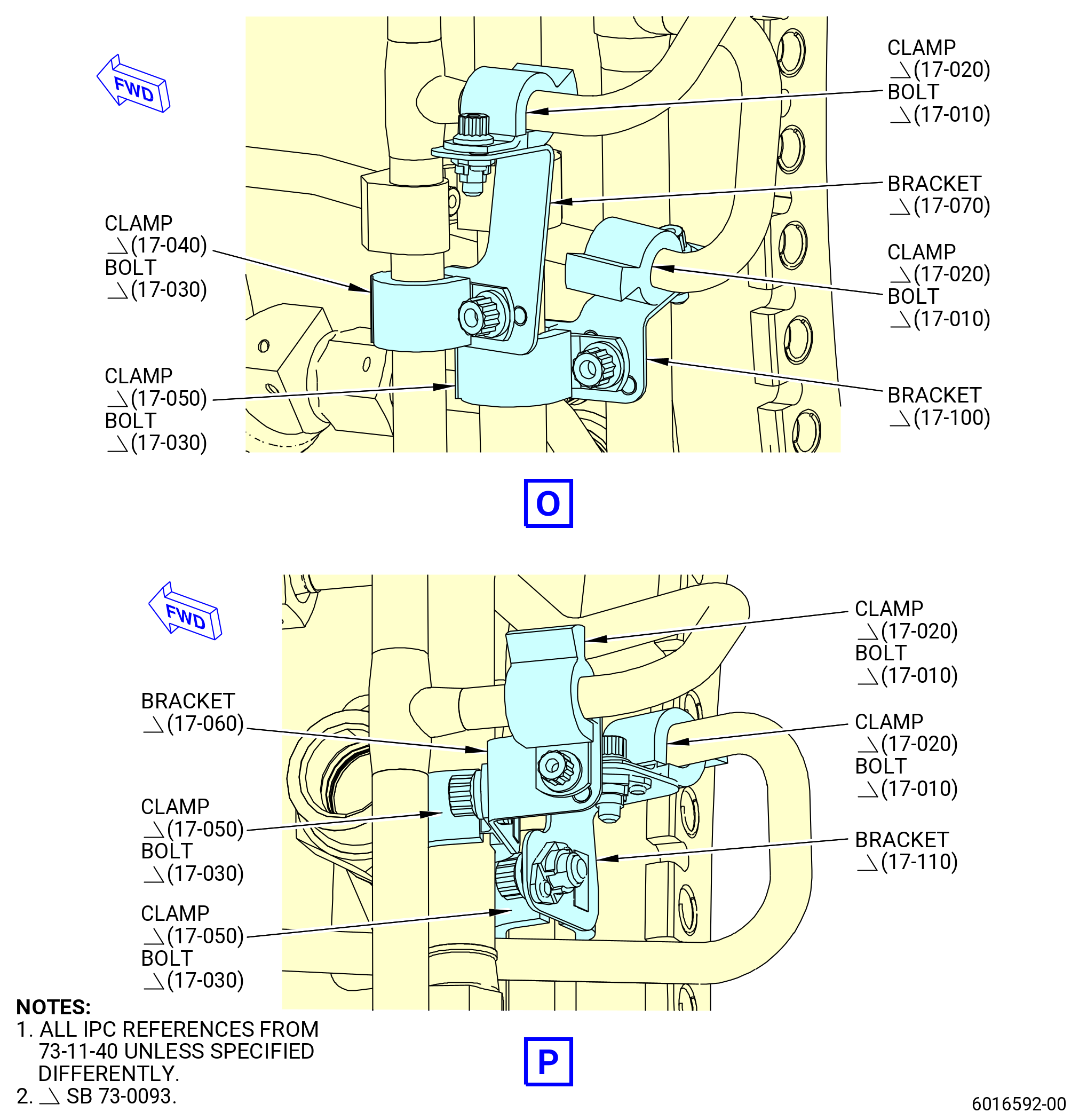
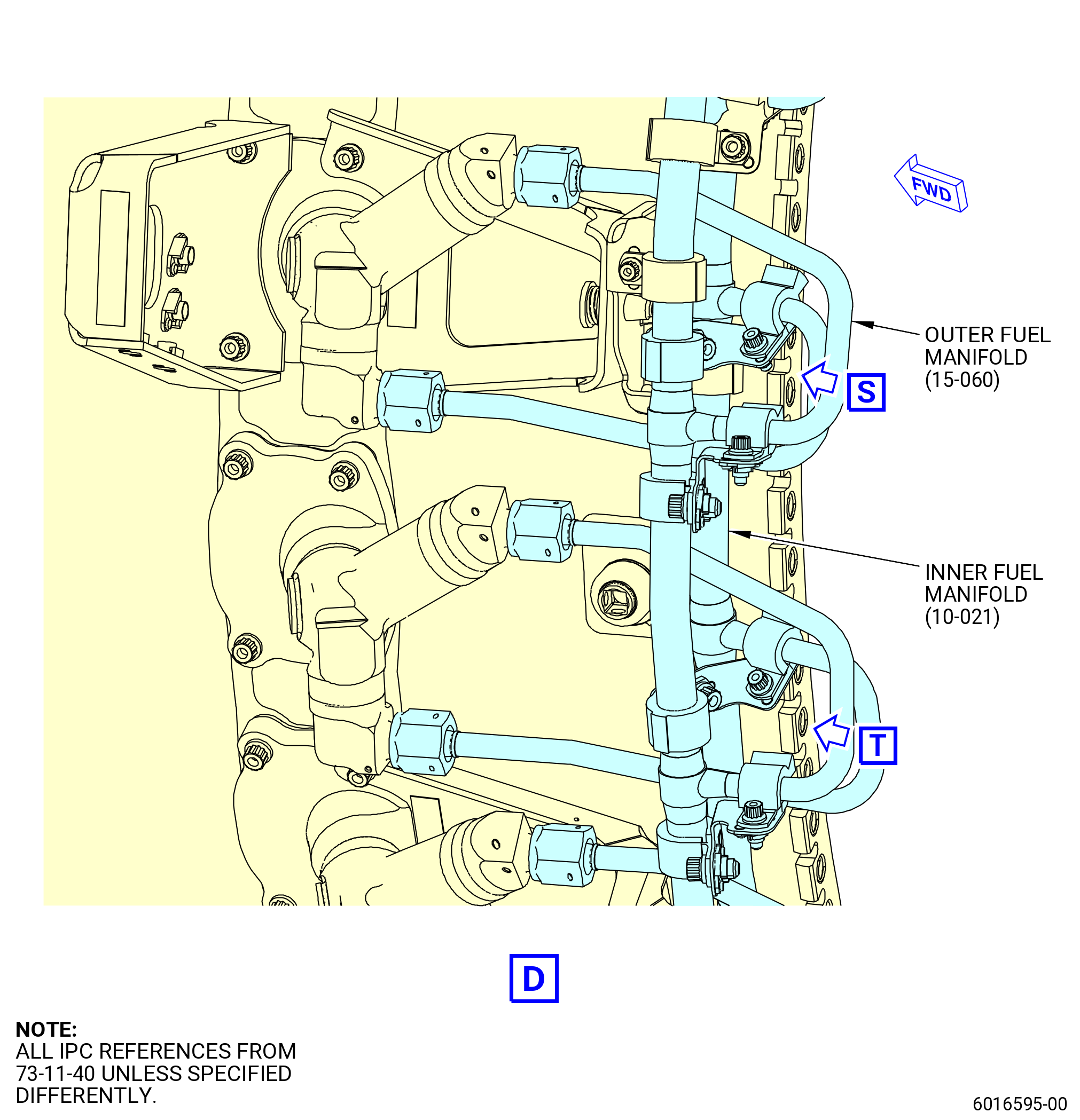
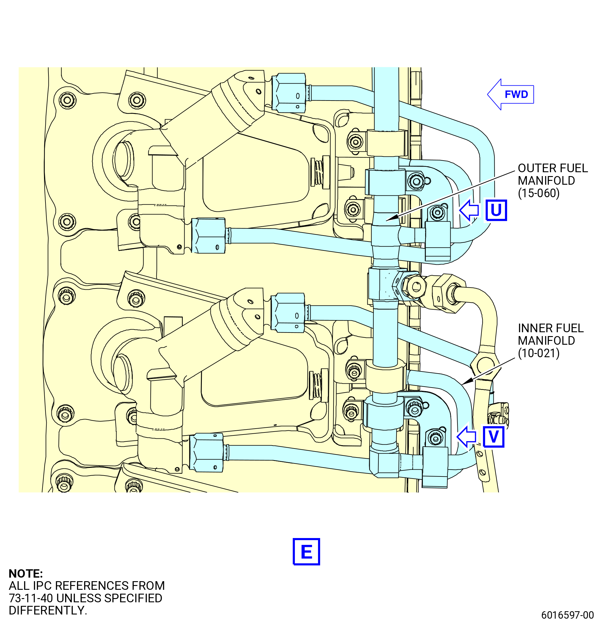
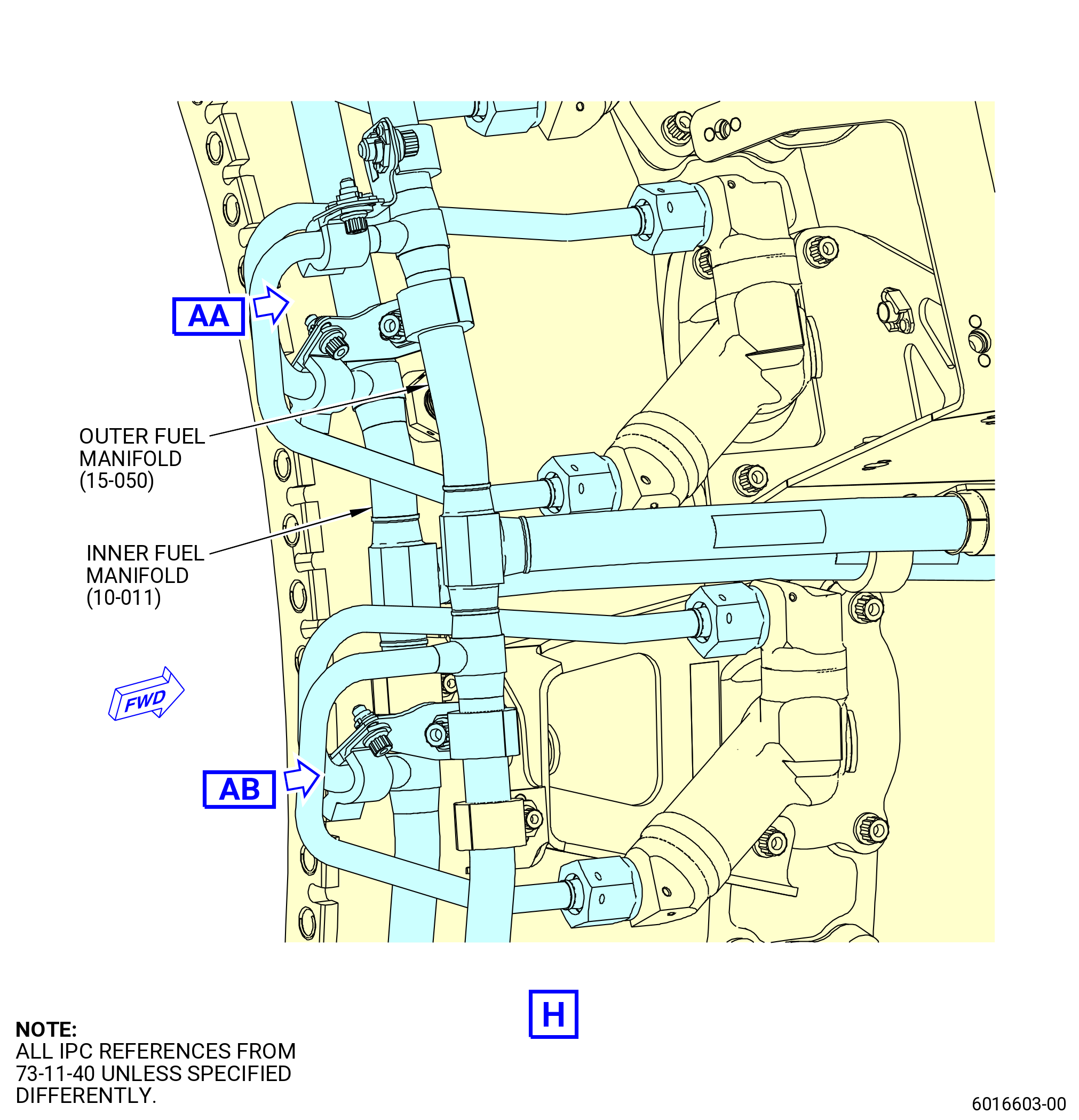
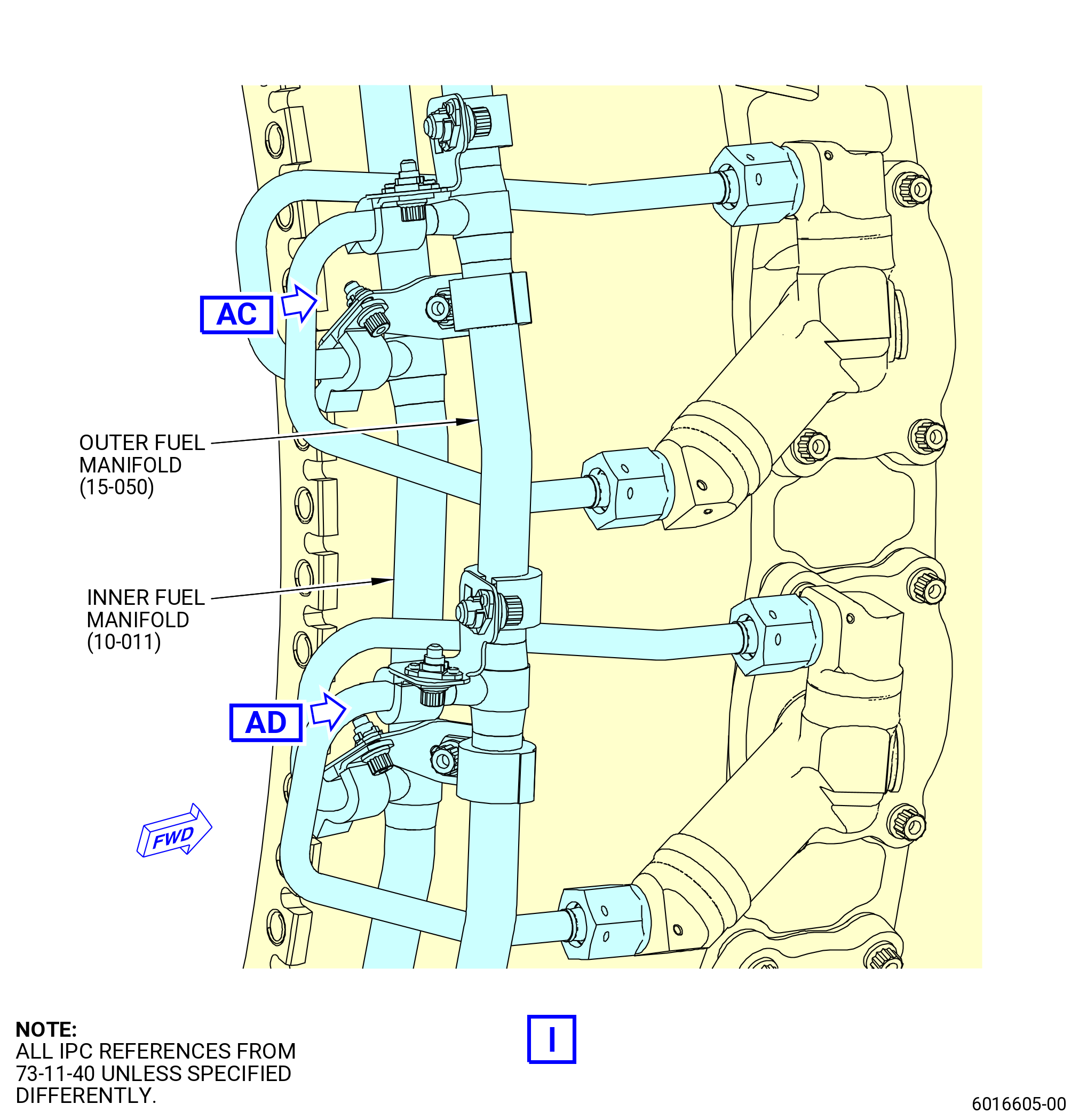
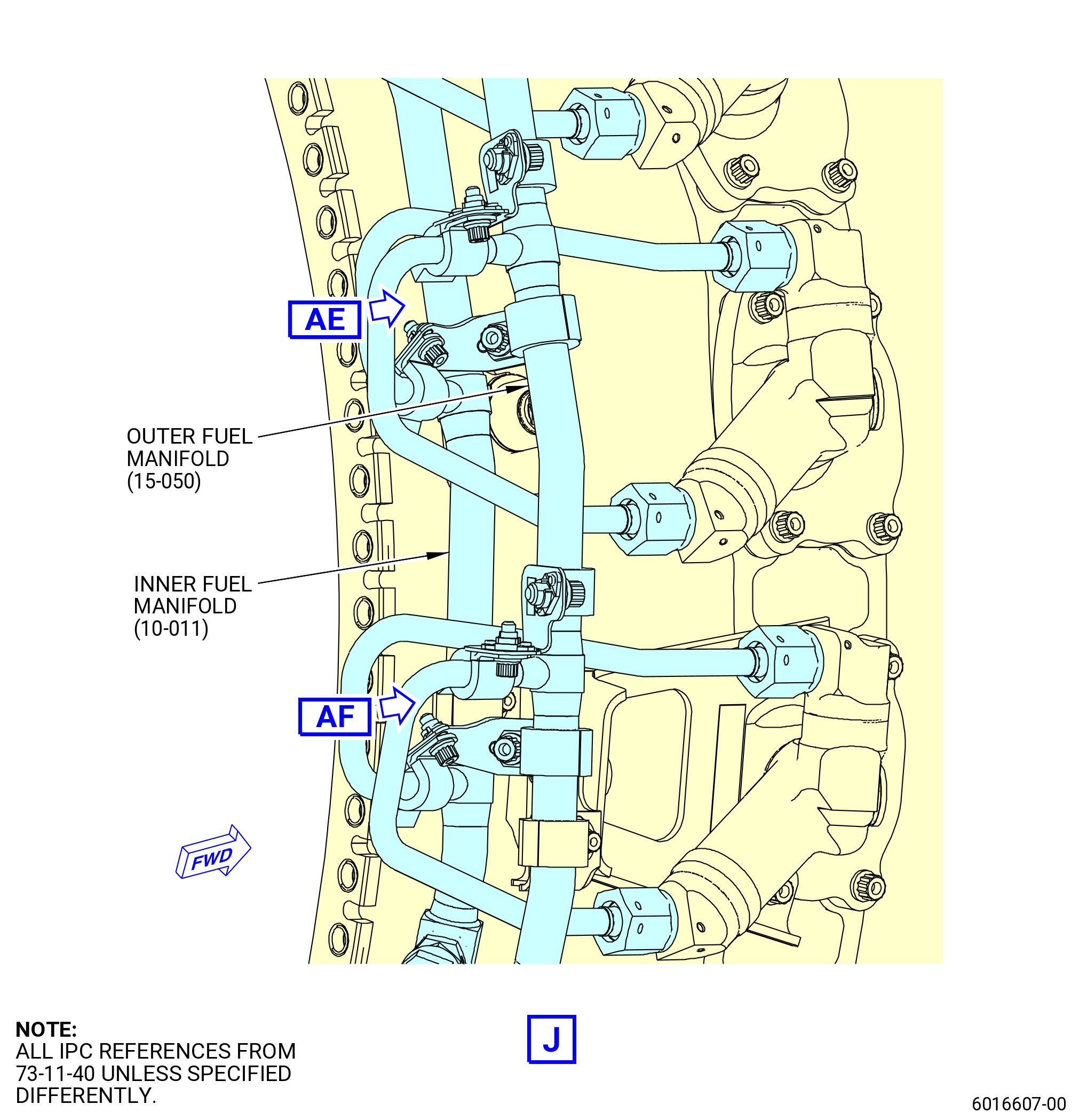
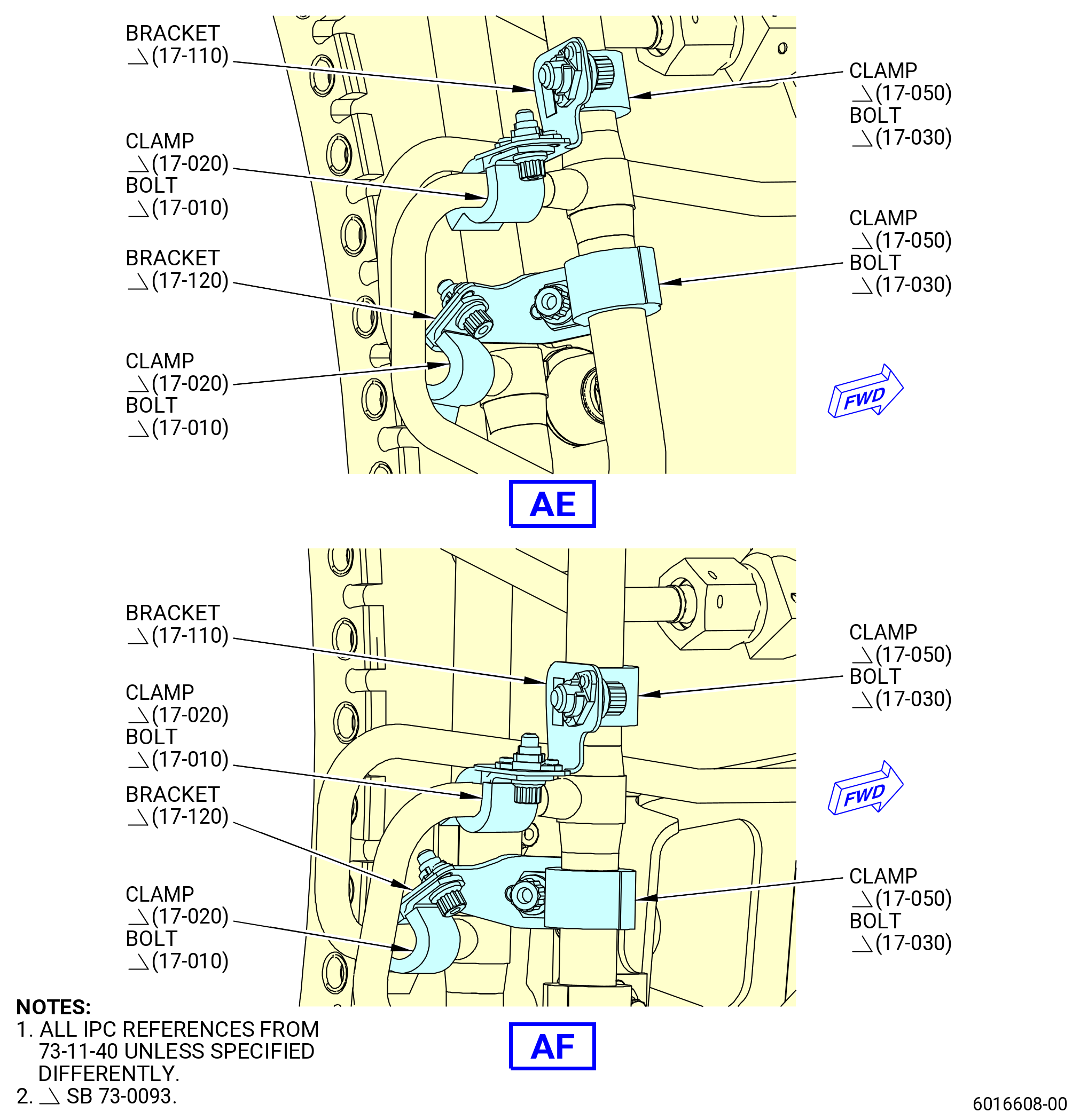
| P. | Remove the new support bracket configuration to the outer segment LS fuel manifold (outer fuel manifold) (15-060 , 73-11-40) (SIN 34202), outer signal enriched LS fuel manifold (outer fuel manifold) (15-040 , 73-11-40) (SIN 34302), inner segment LS fuel manifold (inner fuel manifold) (10-021 , 73-11-40) (SIN 34102), outer segment RS fuel manifold (outer fuel manifold) (15-050 , 73-11-40) (SIN 34201) and inner segment RS fuel manifold (inner fuel manifold) (10-011 , 73-11-40) (SIN 34101). Refer to Figure 517 and as follows: |
| NOTE: |
|
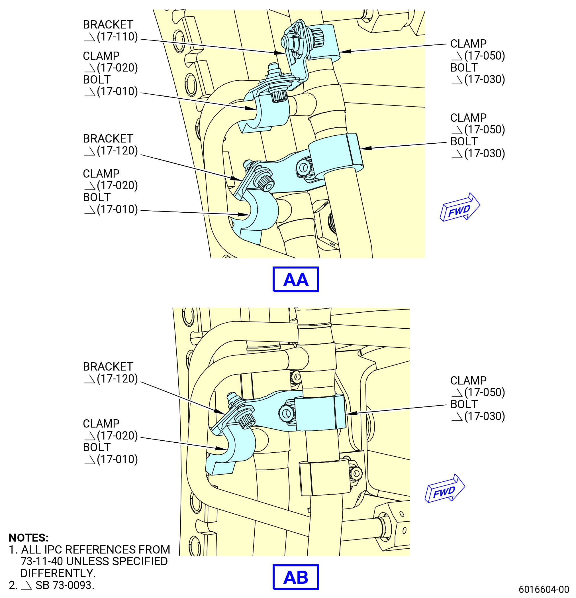
| (1) | Remove one pigtail bracket (17-120 , 73-11-40) (SIN 3411V) that attaches the outer fuel manifold (15-050 , 73-11-40) (SIN 34201) with a cushioned loop clamp (17-050 , 73-11-40) (SIN 3438C) and a machine bolt (17-030 , 73-11-40) (SIN 3432B) to the pigtail of the inner fuel manifold (10-011 , 73-11-40) (SIN 34101) that connects to the fuel nozzle (05-030 , 73-11-30) (SIN 12500) at position 1 with a cushioned loop clamp (17-020 , 73-11-40) (SIN 3438A) and a machine bolt (17-010 , 73-11-40) (SIN 3432A). |
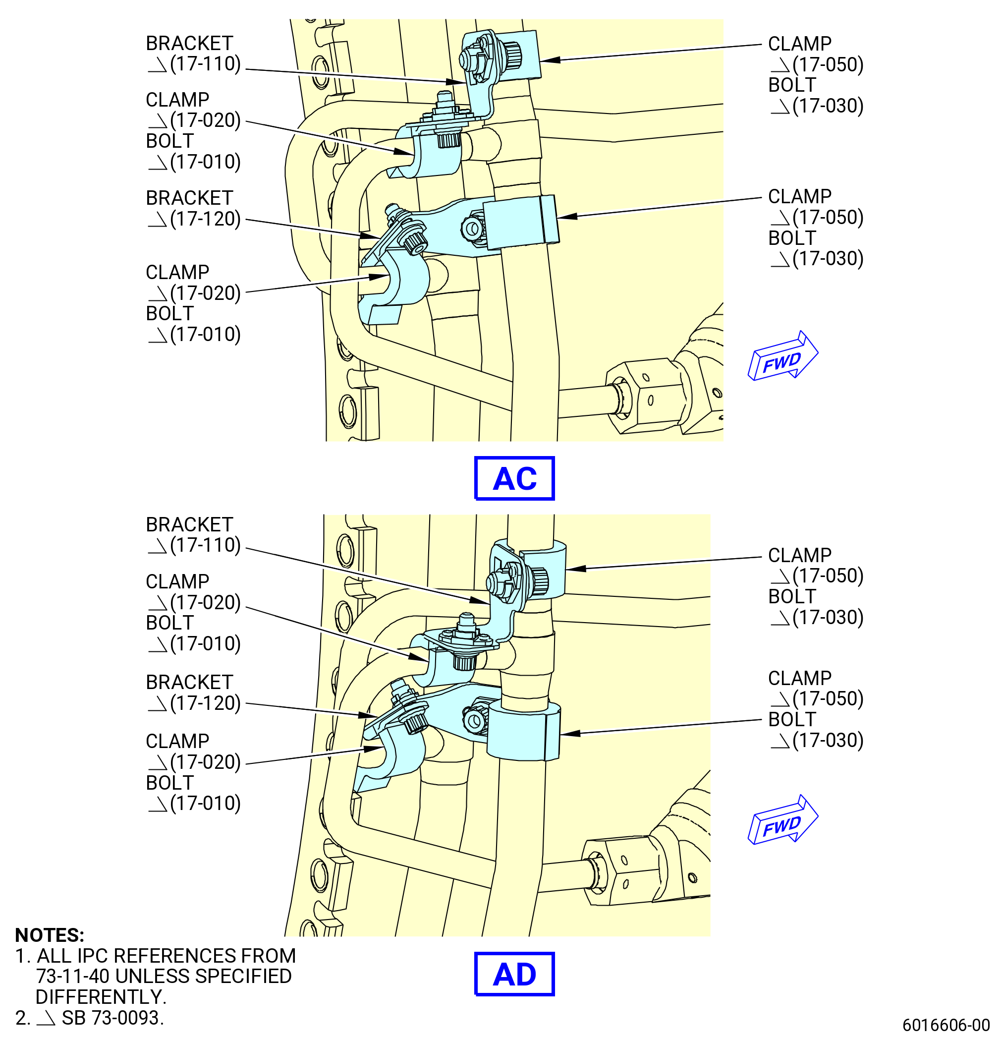
| (2) | Remove one pigtail bracket (17-110 , 73-11-40) (SIN 3411U) that attaches the outer fuel manifold (15-050 , 73-11-40) (SIN 34201) with a cushioned loop clamp (17-050 , 73-11-40) (SIN 3438C) and a machine bolt (17-030 , 73-11-40) (SIN 3432B) to the pigtail of the outer fuel manifold (15-050 , 73-11-40) (SIN 34201) that connects to the fuel nozzle (05-040 , 73-11-30) (SIN 12500) at position 2 with a cushioned loop clamp (17-020 , 73-11-40) (SIN 3438A) and a machine bolt (17-010 , 73-11-40) (SIN 3432A). |
| (3) | Remove one pigtail bracket (17-120 , 73-11-40) (SIN 3411V) that attaches the outer fuel manifold (15-050 , 73-11-40) (SIN 34201) with a cushioned loop clamp (17-050 , 73-11-40) (SIN 3438C) and a machine bolt (17-030 , 73-11-40) (SIN 3432B) to the pigtail of the inner fuel manifold (10-011 , 73-11-40) (SIN 34101) that connects to the fuel nozzle (05-040 , 73-11-30) (SIN 12500) at position 2 with a cushioned loop clamp (17-020 , 73-11-40) (SIN 3438A) and a machine bolt (17-010 , 73-11-40) (SIN 3432A). |
| (4) | Remove one pigtail bracket (17-110 , 73-11-40) (SIN 3411U) that attaches the outer fuel manifold (15-050 , 73-11-40) (SIN 34201) with a cushioned loop clamp (17-050 , 73-11-40) (SIN 3438C) and a machine bolt (17-030 , 73-11-40) (SIN 3432B) to the pigtail of the outer fuel manifold (15-050 , 73-11-40) (SIN 34201) that connects to the fuel nozzle (05-050 , 73-11-30) (SIN 12500) at position 3 with a cushioned loop clamp (17-020 , 73-11-40) (SIN 3438A) and a machine bolt (17-010 , 73-11-40) (SIN 3432A). |
| (5) | Remove one pigtail bracket (17-120 , 73-11-40) (SIN 3411V) that attaches the outer fuel manifold (15-050 , 73-11-40) (SIN 34201) with a cushioned loop clamp (17-050 , 73-11-40) (SIN 3438C) and a machine bolt (17-030 , 73-11-40) (SIN 3432B) to the pigtail of the inner fuel manifold (10-011 , 73-11-40) (SIN 34101) that connects to the fuel nozzle (05-050 , 73-11-30) (SIN 12500) at position 3 with a cushioned loop clamp (17-020 , 73-11-40) (SIN 3438A) and a machine bolt (17-010 , 73-11-40) (SIN 3432A). |
| (6) | Remove one pigtail bracket (17-110 , 73-11-40) (SIN 3411U) that attaches the outer fuel manifold (15-050 , 73-11-40) (SIN 34201) with a cushioned loop clamp (17-050 , 73-11-40) (SIN 3438C) and a machine bolt (17-030 , 73-11-40) (SIN 3432B) to the pigtail of the outer fuel manifold (15-050 , 73-11-40) (SIN 34201) that connects to the fuel nozzle (05-060 , 73-11-30) (SIN 12500) at position 4 with a cushioned loop clamp (17-020 , 73-11-40) (SIN 3438A) and a machine bolt (17-010 , 73-11-40) (SIN 3432A). |
| (7) | Remove one pigtail bracket (17-120 , 73-11-40) (SIN 3411V) that attaches the outer fuel manifold (15-050 , 73-11-40) (SIN 34201) with a cushioned loop clamp (17-050 , 73-11-40) (SIN 3438C) and a machine bolt (17-030 , 73-11-40) (SIN 3432B) to the pigtail of the inner fuel manifold (10-011 , 73-11-40) (SIN 34101) that connects to the fuel nozzle (05-060 , 73-11-30) (SIN 12500) at position 4 with a cushioned loop clamp (17-020 , 73-11-40) (SIN 3438A) and a machine bolt (17-010 , 73-11-40) (SIN 3432A). |
| (8) | Remove one pigtail bracket (17-110 , 73-11-40) (SIN 3411U) that attaches the outer fuel manifold (15-050 , 73-11-40) (SIN 34201) with a cushioned loop clamp (17-050 , 73-11-40) (SIN 3438C) and a machine bolt (17-030 , 73-11-40) (SIN 3432B) to the pigtail of the outer fuel manifold (15-050 , 73-11-40) (SIN 34201) that connects to the fuel nozzle (05-070 , 73-11-30) (SIN 12500) at position 5 with a cushioned loop clamp (17-020 , 73-11-40) (SIN 3438A) and a machine bolt (17-010 , 73-11-40) (SIN 3432A). |
| (9) | Remove one pigtail bracket (17-120 , 73-11-40) (SIN 3411V) that attaches the outer fuel manifold (15-050 , 73-11-40) (SIN 34201) with a cushioned loop clamp (17-050 , 73-11-40) (SIN 3438C) and a machine bolt (17-030 , 73-11-40) (SIN 3432B) to the pigtail of the inner fuel manifold (10-011 , 73-11-40) (SIN 34101) that connects to the fuel nozzle (05-070 , 73-11-30) (SIN 12500) at position 5 with a cushioned loop clamp (17-020 , 73-11-40) (SIN 3438A) and a machine bolt (17-010 , 73-11-40) (SIN 3432A). |
| (10) | Remove one pigtail bracket (17-120 , 73-11-40) (SIN 3411V) that attaches the outer fuel manifold (15-050 , 73-11-40) (SIN 34201) with a cushioned loop clamp (17-050 , 73-11-40) (SIN 3438C) and a machine bolt (17-030 , 73-11-40) (SIN 3432B) to the pigtail of the inner fuel manifold (10-011 , 73-11-40) (SIN 34101) that connects to the fuel nozzle (05-080 , 73-11-30) (SIN 12500) at position 6 with a cushioned loop clamp (17-020 , 73-11-40) (SIN 3438A) and a machine bolt (17-010 , 73-11-40) (SIN 3432A). |
| (11) | Remove one pigtail bracket (17-110 , 73-11-40) (SIN 3411U) that attaches the outer fuel manifold (15-050 , 73-11-40) (SIN 34201) with a cushioned loop clamp (17-050 , 73-11-40) (SIN 3438C) and a machine bolt (17-030 , 73-11-40) (SIN 3432B) to the pigtail of the outer fuel manifold (15-050 , 73-11-40) (SIN 34201) that connects to the fuel nozzle (05-090 , 73-11-30) (SIN 12500) at position 7 with a cushioned loop clamp (17-020 , 73-11-40) (SIN 3438A) and a machine bolt (17-010 , 73-11-40) (SIN 3432A). |
| (12) | Remove one pigtail bracket (17-120 , 73-11-40) (SIN 3411V) that attaches the outer fuel manifold (15-050 , 73-11-40) (SIN 34201) with a cushioned loop clamp (17-050 , 73-11-40) (SIN 3438C) and a machine bolt (17-030 , 73-11-40) (SIN 3432B) to the pigtail of the inner fuel manifold (10-011 , 73-11-40) (SIN 34101) that connects to the fuel nozzle (05-090 , 73-11-30) (SIN 12500) at position 7 with a cushioned loop clamp (17-020 , 73-11-40) (SIN 3438A) and a machine bolt (17-010 , 73-11-40) (SIN 3432A). |
| (13) | Remove one pigtail bracket (17-110 , 73-11-40) (SIN 3411U) that attaches the outer fuel manifold (15-050 , 73-11-40) (SIN 34201) with a cushioned loop clamp (17-050 , 73-11-40) (SIN 3438C) and a machine bolt (17-030 , 73-11-40) (SIN 3432B) to the pigtail of the outer fuel manifold (15-050 , 73-11-40) (SIN 34201) that connects to the fuel nozzle (05-100 , 73-11-30) (SIN 12500) at position 8 with a cushioned loop clamp (17-020 , 73-11-40) (SIN 3438A) and a machine bolt (17-010 , 73-11-40) (SIN 3432A). |
| (14) | Remove one pigtail bracket (17-120 , 73-11-40) (SIN 3411V) that attaches the outer fuel manifold (15-050 , 73-11-40) (SIN 34201) with a cushioned loop clamp (17-050 , 73-11-40) (SIN 3438C) and a machine bolt (17-030 , 73-11-40) (SIN 3432B) to the pigtail of the inner fuel manifold (10-011 , 73-11-40) (SIN 34101) that connects to the fuel nozzle (05-100 , 73-11-30) (SIN 12500) at position 8 with a cushioned loop clamp (17-020 , 73-11-40) (SIN 3438A) and a machine bolt (17-010 , 73-11-40) (SIN 3432A). |
| (15) | Remove one pigtail bracket (17-110 , 73-11-40) (SIN 3411U) that attaches the outer fuel manifold (15-050 , 73-11-40) (SIN 34201) with a cushioned loop clamp (17-050 , 73-11-40) (SIN 3438C) and a machine bolt (17-030 , 73-11-40) (SIN 3432B) to the pigtail of the outer fuel manifold (15-050 , 73-11-40) (SIN 34201) that connects to the fuel nozzle (05-110 , 73-11-30) (SIN 12500) at position 9 with a cushioned loop clamp (17-020 , 73-11-40) (SIN 3438A) and a machine bolt (17-010 , 73-11-40) (SIN 3432A). |
| (16) | Remove one pigtail bracket (17-120 , 73-11-40) (SIN 3411V) that attaches the outer fuel manifold (15-050 , 73-11-40) (SIN 34201) with a cushioned loop clamp (17-050 , 73-11-40) (SIN 3438C) and a machine bolt (17-030 , 73-11-40) (SIN 3432B) to the pigtail of the inner fuel manifold (10-011 , 73-11-40) (SIN 34101) that connects to the fuel nozzle (05-110 , 73-11-30) (SIN 12500) at position 9 with a cushioned loop clamp (17-020 , 73-11-40) (SIN 3438A) and a machine bolt (17-010 , 73-11-40) (SIN 3432A). |
| (17) | Remove one pigtail bracket (17-110 , 73-11-40) (SIN 3411U) that attaches the outer fuel manifold (15-050 , 73-11-40) (SIN 34201) with a cushioned loop clamp (17-050 , 73-11-40) (SIN 3438C) and a machine bolt (17-030 , 73-11-40) (SIN 3432B) to the pigtail of the outer fuel manifold (15-050 , 73-11-40) (SIN 34201) that connects to the fuel nozzle (05-120 , 73-11-30) (SIN 12500) at position 10 with a cushioned loop clamp (17-020 , 73-11-40) (SIN 3438A) and a machine bolt (17-010 , 73-11-40) (SIN 3432A). |
| (18) | Remove one pigtail bracket (17-120 , 73-11-40) (SIN 3411V) that attaches the outer fuel manifold (15-050 , 73-11-40) (SIN 34201) with a cushioned loop clamp (17-050 , 73-11-40) (SIN 3438C) and a machine bolt (17-030 , 73-11-40) (SIN 3432B) to the pigtail of the inner fuel manifold (10-011 , 73-11-40) (SIN 34101) that connects to the fuel nozzle (05-120 , 73-11-30) (SIN 12500) at position 10 with a cushioned loop clamp (17-020 , 73-11-40) (SIN 3438A) and a machine bolt (17-010 , 73-11-40) (SIN 3432A). |
| (19) | Remove one pigtail bracket (17-090 , 73-11-40) (SIN 3411Y) that attaches the outer fuel manifold (15-050 , 73-11-40) (SIN 34201) with a cushioned loop clamp (17-020 , 73-11-40) (SIN 3438A) and a machine bolt (17-010 , 73-11-40) (SIN 3432A) to the pigtail of the inner fuel manifold (10-011 , 73-11-40) (SIN 34101) that connects to the fuel nozzle (05-130 , 73-11-30) (SIN 12500) at position 11 with a cushioned loop clamp (17-020 , 73-11-40) (SIN 3438A) and a machine bolt (17-010 , 73-11-40) (SIN 3432A). |
| (20) | Remove one pigtail bracket (17-080 , 73-11-40) (SIN 3431J) that attaches the outer fuel manifold (15-060 , 73-11-40) (SIN 34202) with a cushioned loop clamp (17-050 , 73-11-40) (SIN 3438C) and a machine bolt (17-030 , 73-11-40) (SIN 3432B) to the pigtail of the outer fuel manifold (15-060 , 73-11-40) (SIN 34202) that connects to the fuel nozzle (05-140 , 73-11-30) (SIN 12500) at position 12 with a cushioned loop clamp (17-020 , 73-11-40) (SIN 3438A) and a machine bolt (17-010 , 73-11-40) (SIN 3432A). |
| (21) | Remove one pigtail bracket (17-080 , 73-11-40) (SIN 3431J) that attaches the outer fuel manifold (15-060 , 73-11-40) (SIN 34202) with a cushioned loop clamp (17-050 , 73-11-40) (SIN 3438C) and a machine bolt (17-030 , 73-11-40) (SIN 3432B) to the pigtail of the outer fuel manifold (15-060 , 73-11-40) (SIN 34202) that connects to the fuel nozzle (05-150 , 73-11-30) (SIN 12500) at position 13 with a cushioned loop clamp (17-020 , 73-11-40) (SIN 3438A) and a machine bolt (17-010 , 73-11-40) (SIN 3432A). |
| (22) | Remove one pigtail bracket (17-110 , 73-11-40) (SIN 3411U) that attaches the outer fuel manifold (15-060 , 73-11-40) (SIN 34202) with a cushioned loop clamp (17-050 , 73-11-40) (SIN 3438C) and a machine bolt (17-030 , 73-11-40) (SIN 3432B) to the pigtail of the outer fuel manifold (15-060 , 73-11-40) (SIN 34202) that connects to the fuel nozzle (05-160 , 73-11-30) (SIN 12500) at position 14 with a cushioned loop clamp (17-020 , 73-11-40) (SIN 3438A) and a machine bolt (17-010 , 73-11-40) (SIN 3432A). |
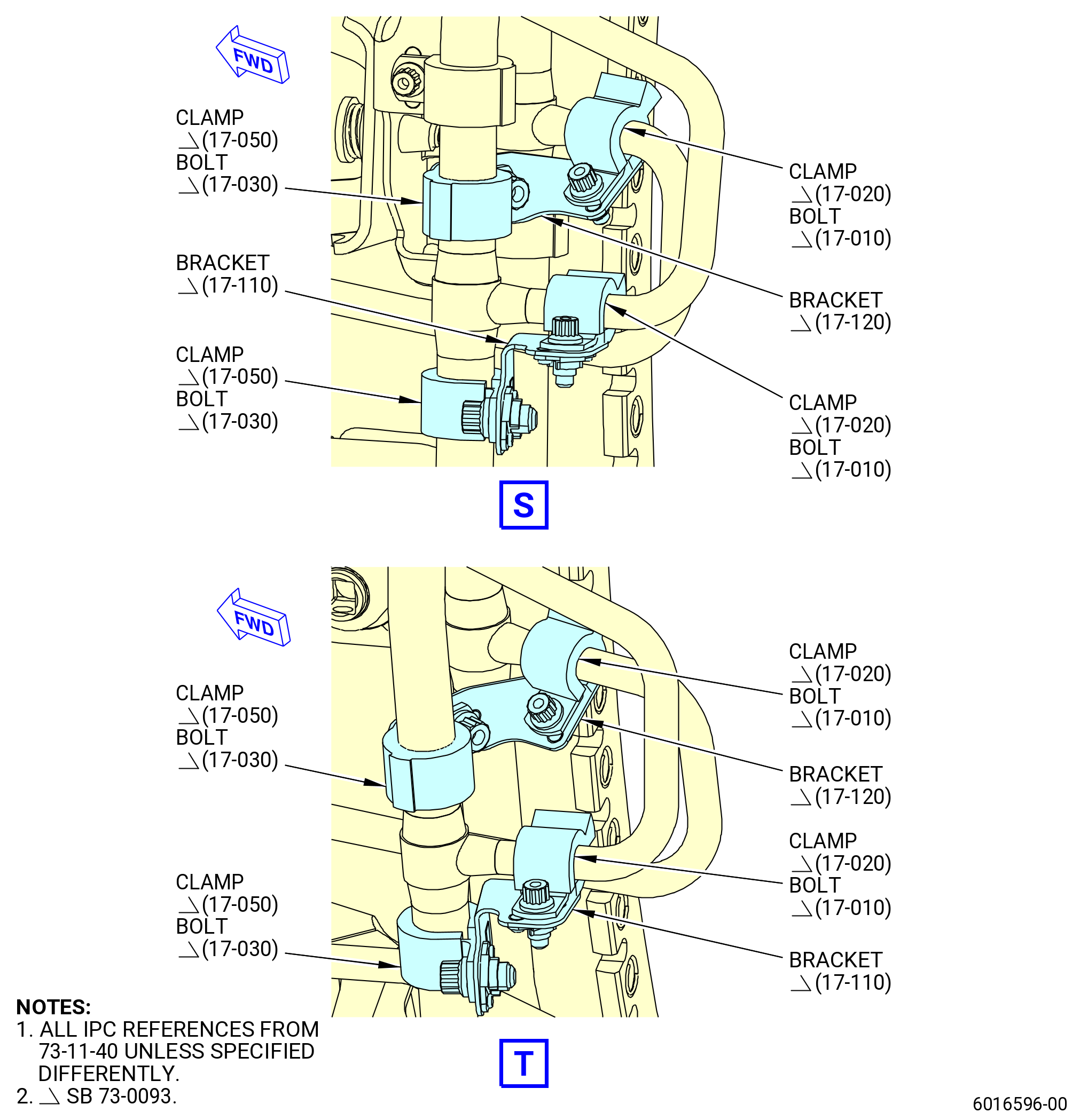
| (23) | Remove one pigtail bracket (17-120 , 73-11-40) (SIN 3411V) that attaches the outer fuel manifold (15-060 , 73-11-40) (SIN 34202) with a cushioned loop clamp (17-050 , 73-11-40) (SIN 3438C) and a machine bolt (17-030 , 73-11-40) (SIN 3432B) to the pigtail of the inner fuel manifold (10-021 , 73-11-40) (SIN 34102) that connects to the fuel nozzle (05-160 , 73-11-30) (SIN 12500) at position 14 with a cushioned loop clamp (17-030 , 73-11-40) (SIN 3438A) and a machine bolt (17-010 , 73-11-40) (SIN 3432A). |
| (24) | Remove one pigtail bracket (17-110 , 73-11-40) (SIN 3411U) that attaches the outer fuel manifold (15-060 , 73-11-40) (SIN 34202) with a cushioned loop clamp (17-050 , 73-11-40) (SIN 3438C) and a machine bolt (17-030 , 73-11-40) (SIN 3432B) to the pigtail of the outer fuel manifold (15-060 , 73-11-40) (SIN 34202) that connects to the fuel nozzle (05-170 , 73-11-30) (SIN 12500) at position 15 with a cushioned loop clamp (17-020 , 73-11-40) (SIN 3438A) and a machine bolt (17-010 , 73-11-40) (SIN 3432A). |
| (25) | Remove one pigtail bracket (17-120 , 73-11-40) (SIN 3411V) that attaches the outer fuel manifold (15-060 , 73-11-40) (SIN 34202) with a cushioned loop clamp (17-050 , 73-11-40) (SIN 3438C) and a machine bolt (17-030 , 73-11-40) (SIN 3432B) to the pigtail of the inner fuel manifold (10-021 , 73-11-40) (SIN 34102) that connects to the fuel nozzle (05-170 , 73-11-30) (SIN 12500) at position 15 with a cushioned loop clamp (17-020 , 73-11-40) (SIN 3438A) and a machine bolt (17-010 , 73-11-40) (SIN 3432A). |
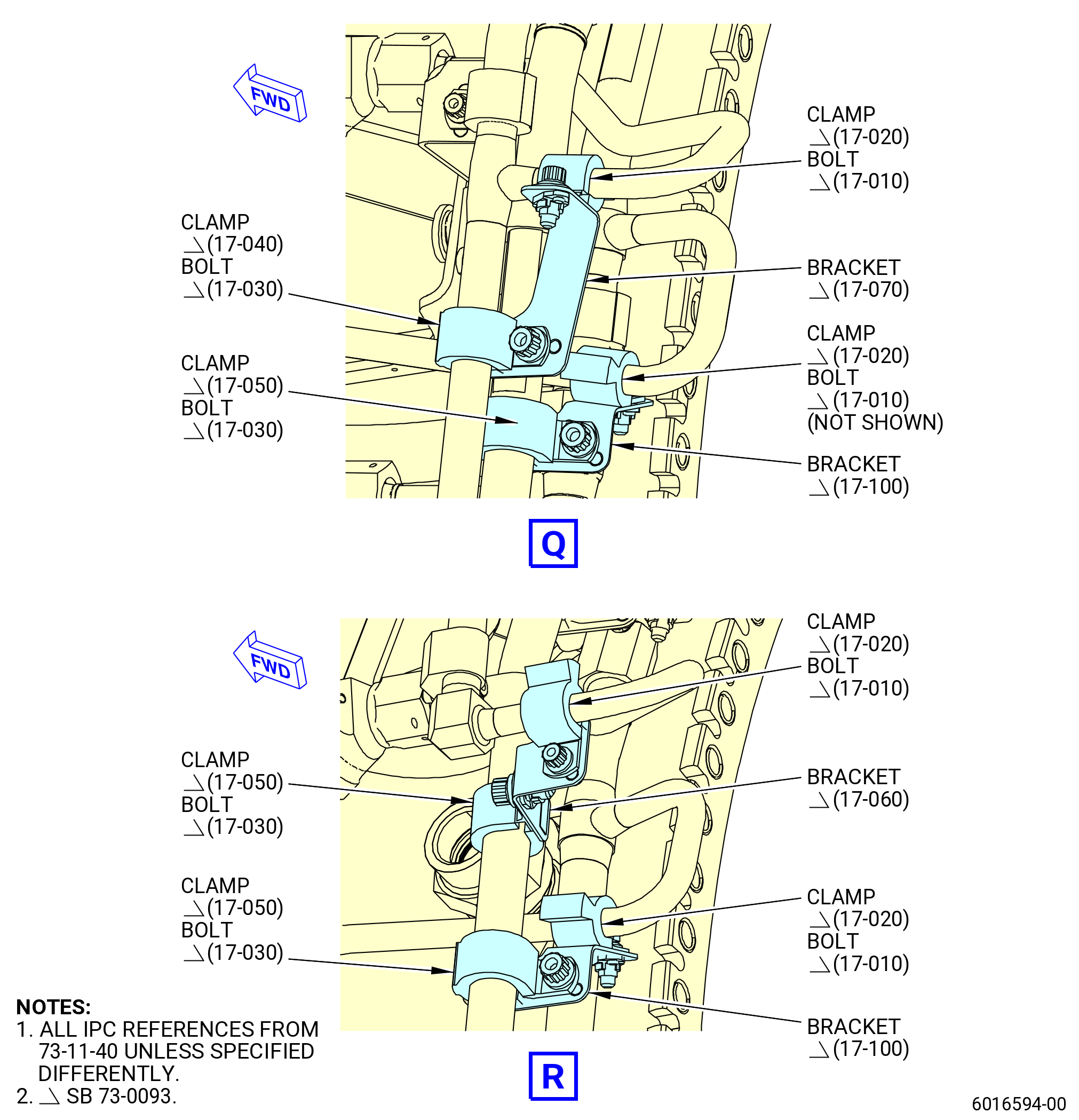
| (26) | Remove one pigtail bracket (17-100 , 73-11-40) (SIN 3411W) that attaches the outer fuel manifold (15-060 , 73-11-40) (SIN 34202) with a cushioned loop clamp (17-050 , 73-11-40) (SIN 3438C) and a machine bolt (17-030 , 73-11-40) (SIN 3432B) to the pigtail of the inner fuel manifold (10-021 , 73-11-40) (SIN 34102) that connects to the fuel nozzle (05-180 , 73-11-30) (SIN 12500) at position 16 with a cushioned loop clamp (17-020 , 73-11-40) (SIN 3438A) and a machine bolt (17-010 , 73-11-40) (SIN 3432A). |
| (27) | Remove one pigtail bracket (17-060 , 73-11-40) (SIN 3431K) that attaches the outer fuel manifold (15-060 , 73-11-40) (SIN 34202) with a cushioned loop clamp (17-050 , 73-11-40) (SIN 3438C) and a machine bolt (17-030 , 73-11-40) (SIN 3432B) to the pigtail of the outer fuel manifold (15-060 , 73-11-40) (SIN 34302) that connects to the fuel nozzle (05-180 , 73-11-30) (SIN 12500) at position 16 with a cushioned loop clamp (17-020 , 73-11-40) (SIN 3438A) and a machine bolt (17-010 , 73-11-40) (SIN 3432A). |
| (28) | Remove one pigtail bracket (17-100 , 73-11-40) (SIN 3411W) that attaches the outer fuel manifold (15-060 , 73-11-40) (SIN 34202) with a cushioned loop clamp (17-050 , 73-11-40) (SIN 3438C) and a machine bolt (17-030 , 73-11-40) (SIN 3432B) to the pigtail of the inner fuel manifold (10-021 , 73-11-40) (SIN 34102) that connects to the fuel nozzle (05-190 , 73-11-30) (SIN 12500) at position 17 with a cushioned loop clamp (17-020 , 73-11-40) (SIN 3438A) and a machine bolt (17-010 , 73-11-40) (SIN 3432A). |
| (29) | Remove one pigtail bracket (17-070 , 73-11-40) (SIN 3431L) that attaches the outer fuel manifold (15-040 , 73-11-40) (SIN 34302) with a cushioned loop clamp (17-040 , 73-11-40) (SIN 3438B) and a machine bolt (17-030 , 73-11-40) (SIN 3432B) to the pigtail of the outer fuel manifold (15-040 , 73-11-40) (SIN 34302) that connects to the fuel nozzle (05-190 , 73-11-30) (SIN 12500) at position 17 with a cushioned loop clamp (17-020 , 73-11-40) (SIN 3438A) and a machine bolt (17-010 , 73-11-40) (SIN 3432A). |
| (30) | Remove one pigtail bracket (17-060 , 73-11-40) (SIN 3431K) that attaches the outer fuel manifold (15-060 , 73-11-40) (SIN 34202) with a cushioned loop clamp (17-050 , 73-11-40) (SIN 3438C) and a machine bolt (17-030 , 73-11-40) (SIN 3432B) to the pigtail of the outer fuel manifold (15-040 , 73-11-40) (SIN 34302) that connects to the fuel nozzle (05-200 , 73-11-30) (SIN 12500) at position 18 with a cushioned loop clamp (17-020 , 73-11-40) (SIN 3438A) and a machine bolt (17-010 , 73-11-40) (SIN 3432A). |
| (31) | Remove one pigtail bracket (17-110 , 73-11-40) (SIN 3411U) that attaches the inner fuel manifold (10-021 , 73-11-40) (SIN 34102) with a cushioned loop clamp (17-050 , 73-11-40) (SIN 3438C) and a machine bolt (17-030 , 73-11-40) (SIN 3432B) to the pigtail of the inner fuel manifold (10-021 , 73-11-40) (SIN 34102) that connects to the fuel nozzle (05-200 , 73-11-30) (SIN 12500) at position 18 with a cushioned loop clamp (17-020 , 73-11-40) (SIN 3438A) and a machine bolt (17-010 , 73-11-40) (SIN 3432A). |
| (32) | Remove one pigtail bracket (17-070 , 73-11-40) (SIN 3431L) that attaches the outer fuel manifold (15-040 , 73-11-40) (SIN 34302) with a cushioned loop clamp (17-040 , 73-11-40) (SIN 3438B) and a machine bolt (17-030 , 73-11-40) (SIN 3432B) to the pigtail of the outer fuel manifold (15-040 , 73-11-40) (SIN 34302) that connects to the fuel nozzle (05-210 , 73-11-30) (SIN 12500) at position 19 with a cushioned loop clamp (17-020 , 73-11-40) (SIN 3438A) and a machine bolt (17-010 , 73-11-40) (SIN 3432A). |
| (33) | Remove one pigtail bracket (17-100 , 73-11-40) (SIN 3411W) that attaches the outer fuel manifold (15-060 , 73-11-40) (SIN 34202) with a cushioned loop clamp (17-050 , 73-11-40) (SIN 3438C) and a machine bolt (17-030 , 73-11-40) (SIN 3432B) to the pigtail of the inner fuel manifold (10-021 , 73-11-40) (SIN 34102) that connects to the fuel nozzle (05-210 , 73-11-30) (SIN 12500) at position 19 with a cushioned loop clamp (17-020 , 73-11-40) (SIN 3438A) and a machine bolt (17-010 , 73-11-40) (SIN 3432A). |
| (34) | Remove one pigtail bracket (17-110 , 73-11-40) (SIN 3411U) that attaches the outer fuel manifold (15-060 , 73-11-40) (SIN 34202) with a cushioned loop clamp (17-050 , 73-11-40) (SIN 3438C) and a machine bolt (17-030 , 73-11-40) (SIN 3432B) to the pigtail of the outer fuel manifold (15-060 , 73-11-40) (SIN 34202) that connects to the fuel nozzle (05-220 , 73-11-30) (SIN 12500) at position 20 with a cushioned loop clamp (17-020 , 73-11-40) (SIN 3438A) and a machine bolt (17-010 , 73-11-40) (SIN 3432A). |
| (35) | Remove one pigtail bracket (17-110 , 73-11-40) (SIN 3411U) that attaches the inner fuel manifold (10-021 , 73-11-40) (SIN 34102) with a cushioned loop clamp (17-050 , 73-11-40) (SIN 3438C) and a machine bolt (17-030 , 73-11-40) (SIN 3432B) to the pigtail of the inner fuel manifold (10-021 , 73-11-40) (SIN 34102) that connects to the fuel nozzle (05-220 , 73-11-30) (SIN 12500) at position 20 with a cushioned loop clamp (17-020 , 73-11-40) (SIN 3438A) and a machine bolt (17-010 , 73-11-40) (SIN 3432A). |
| (36) | Remove one pigtail bracket (17-110 , 73-11-40) (SIN 3411U) that attaches the outer fuel manifold (15-060 , 73-11-40) (SIN 34202) with a cushioned loop clamp (17-050 , 73-11-40) (SIN 3438C) and a machine bolt (17-030 , 73-11-40) (SIN 3432B) to the pigtail of the outer fuel manifold (15-060 , 73-11-40) (SIN 34202) that connects to the fuel nozzle (05-230 , 73-11-30) (SIN 12500) at position 21 with a cushioned loop clamp (17-020 , 73-11-40) (SIN 3438A) and a machine bolt (17-010 , 73-11-40) (SIN 3432A). |
| (37) | Remove one pigtail bracket (17-120 , 73-11-40) (SIN 3411V) that attaches the outer fuel manifold (15-060 , 73-11-40) (SIN 34202) with a cushioned loop clamp (17-050 , 73-11-40) (SIN 3438C) and a machine bolt (17-030 , 73-11-40) (SIN 3432B) to the pigtail of the inner fuel manifold (10-021 , 73-11-40) (SIN 34102) that connects to the fuel nozzle (05-230 , 73-11-30) (SIN 12500) at position 21 with a cushioned loop clamp (17-020 , 73-11-40) (SIN 3438A) and a machine bolt (17-010 , 73-11-40) (SIN 3432A). |
| (38) | Remove one pigtail bracket (17-110 , 73-11-40) (SIN 3411U) that attaches the outer fuel manifold (15-060 , 73-11-40) (SIN 34202) with a cushioned loop clamp (17-050 , 73-11-40) (SIN 3438C) and a machine bolt (17-030 , 73-11-40) (SIN 3432B) to the pigtail of the outer fuel manifold (15-060 , 73-11-40) (SIN 34202) that connects to the fuel nozzle (05-240 , 73-11-30) (SIN 12500) at position 22 with a cushioned loop clamp (17-020 , 73-11-40) (SIN 3438A) and a machine bolt (17-010 , 73-11-40) (SIN 3432A). |
| (39) | Remove one pigtail bracket (17-120 , 73-11-40) (SIN 3411V) that attaches the outer fuel manifold (15-060 , 73-11-40) (SIN 34202) with a cushioned loop clamp (17-050 , 73-11-40) (SIN 3438C) and a machine bolt (17-030 , 73-11-40) (SIN 3432B) to the pigtail of the inner fuel manifold (10-021 , 73-11-40) (SIN 34102) that connects to the fuel nozzle (05-240 , 73-11-30) (SIN 12500) at position 22 with a cushioned loop clamp (17-020 , 73-11-40) (SIN 3438A) and a machine bolt (17-010 , 73-11-40) (SIN 3432A). |
| (40) | Remove, if attached, the C10-225 PTFE coated tape or C10-230 PTFE tape from the outer fuel manifolds and inner fuel manifolds. |
| NOTE: |
|
| * * * END SB 73-0093 |
|
|
|
|
|
|
|
|
|
|
|
|
|
|
|
|
|
|
|
|
|
|
| Subtask 72-50-00-030-082 |
| * * * FOR 1B/P/G03.1B/P/G04.1B/P1/G01 |
| * * * PRE SB 72-0155( CDN Module without PIP 2 Configuration ) |
| Q. | Remove the fuel manifolds from the combustor diffuser nozzle (CDN) assembly. Refer to Figure 518 and as follows: |
| NOTE: |
|
| (1) | Remove the bolts and loop cushion clamps that attach the fuel manifolds to the damper brackets. |
| (2) | Fully loosen the coupling nuts that attach the fuel manifolds to the fuel nozzles. |
| (3) | Remove the fuel manifolds. |
| * * * END PRE SB 72-0155 |
| Subtask 72-50-00-030-085 |
| * * * FOR ALL PIP 2 |
| * * * SB 72-0155( CDN Module PIP 2 Configuration ) |
| Q.A. | Remove the fuel manifolds from the combustor diffuser nozzle (CDN) assembly. Refer to Figure 518 and as follows: |
| NOTE: |
|
| (1) | Remove the bolts and loop cushion clamps that attach the fuel manifolds to the damper brackets. |
| (2) | Fully loosen the coupling nuts that attach the fuel manifolds to the fuel nozzles and the fuel manifold (10-100 , 73-11-40) (SIN 3410J) from the manifolds. Refer to Figure 518. |
| (3) | Remove the fuel manifolds and discard packings (10-140 , 73-11-40) (SIN 3415J). |
| * * * END SB 72-0155 |
|
|
| Subtask 72-50-00-030-050 |
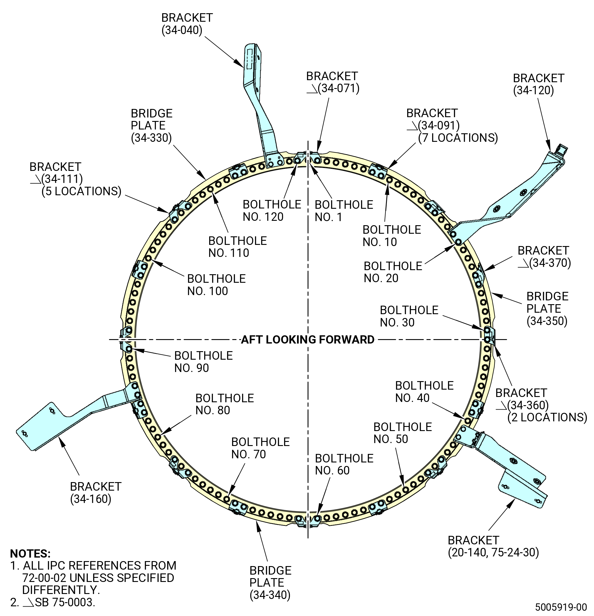
| R. | Remove the flange hardware and brackets from each bolthole location at the CDN/HPT stage 2 nozzle flange as follows. Refer to Figure 519 and Figure 519A. |
| (1) | Remove brackets from the aft side of the CDN/HPT stage 2 nozzle flange. |
| (2) | Discard the flange nuts. |
| (3) | Remove the three bridge plates from the CDN/HPT stage 2 nozzle flange. |
| (4) | Discard the bridge plates (34-330 , 72-00-02) (SIN 17411), (34-340 , 72-00-02) (SIN 17412), and (34-350 , 72-00-02) (SIN 17413). |
|
|
| Subtask 72-50-00-030-051 |
| S. | Remove the HPT stage 2 nozzle assembly from the CDN assembly as follows: |
| Subtask 72-50-00-030-052 |
| (1) | Install the 11C3159 guide on the aft shaft of the HPT rotor assembly (34-020 , 72-00-02) (SIN 15000) or (34-021 , 72-00-02) (SIN 15000). Refer to Figure 520 and do as follows: |
| WARNING: |
|
| (a) | Use an overhead hoist to lift the 11C3159 guide and align it with the aft end of the HPT rotor shaft. |
| (b) | Turn the 11C3159 guide to engage the threads on the HPT rotor shaft. |
| (c) | Use a breaker bar through the 0.515 inch (13.08 mm) diameter holes to tighten the 11C3159 guide . |
| Subtask 72-50-00-030-080 |
| (2) | If necessary, turn the 11C3143hanger install fixture aft side up for installation of the HPT stage 2 nozzle assembly as follows. Refer to Figure 521. |
| (a) | Attach the lift sling (item 10) to an overhead hoist. Lift the lift bar (item 7). |
| (b) | Lower the lift bar (item 7) to the adapter (item 4). |
| (c) | Attach the clevises (item 6) to the adapter (item 4) at the hole with the mark TOOL with the quick release pins (item 13). |
| (d) | Make sure that the quick release pins (item 12) are installed through the lift bar (item 7) and engaged in the plate of the clevises (item 6). |
| WARNING: |
|
| (e) | Lift the base (item 2 or item 29) with the hoist. |
| (f) | Remove the quick release pins (item 12). Turn the base (item 2 or item 29) aft side up. Engage the quick release pins (item 12). Lower the base (item 2 or item 29) on table. |
| (g) | Remove the quick release pins (item 13) from the clevises (item 6). |
| (h) | Remove the lift bar (item 7) from the adapter (item 4). |
| Subtask 72-50-00-030-079 |
| (3) | Install the 11C3434 lift/turn fixture on the aft flange of the HPT stage 2 nozzle assembly as follows. Refer to Figure 520. |
| (a) | Attach an overhead hoist to a three-legged sling. |
| (b) | Attach the three-legged sling to the three shackles (item 5) on the lift and turn adapter (item 2). |
| (c) | Make sure that the 11C3140 protector is installed on the HPT stage 2 nozzle (34-010 , 72-00-02) (SIN 17400) or (34-011 , 72-00-02) (SIN 17400) or (34-012 , 72-00-02) (SIN 17400). |
| WARNING: |
|
| (d) | Lift the 11C3434 lift/turn fixture and engage the 11C3159 guide in the center hub of the lift and turn fixture. |
| (e) | Align the foot of the adapter (item 2) of the 11C3434 lift/turn fixture marked TOP with the TVCL of the HPT stage 2 nozzle assembly. |
| (f) | Align the offset bolthole at TVCL in the aft flange of the HPT stage 2 nozzle assembly with the offset bolthole in the adapter (item 2) marked TOP. |
| (g) | Lower the 11C3434 lift/turn fixture to the aft flange of the HPT stage 2 nozzle assembly. |
| (h) | Attach the 11C3434 lift/turn fixture to the aft flange of the HPT stage 2 nozzle assembly with the cap screws (item 6), washers (item 9), and nuts (item 7). Put the cap screw heads on the aft side of the flange and the washers and nuts on the forward side of the flange. Tighten the nuts (item 7) with a wrench. |
| (4) | Lift the HPT stage 2 nozzle assembly from the CDN assembly. |
| (5) | Alternative Procedure Available. Install the HPT stage 2 nozzle assembly aft side up on the 11C3143 hanger install fixture as follows. Refer to Figure 521. |
| (a) | Find the word TOP marked on the outer diameter (OD) of the HPT stator case aft flange. Write the words TOP FORWARD, with a C05-003 pen, on the OD of the HPT stator case forward flange. |
| (b) | Loosen the capscrews to put the hook clamps (item 19) away from the step in the base (item 2 or item 29) of the 11C3143 hanger install fixture. |
| (c) | Find the TOP VERTICAL mark on the base (item 2 or item 29) of the 11C3143 hanger install fixture. |
| (d) | Lift the HPT stage 2 nozzle assembly from the CDN assembly. |
| (e) | Lower the HPT stage 2 nozzle assembly on the base (item 2 or item 29) of the 11C3143 hanger install fixture and align the top vertical centerlines of the hanger install fixture and the HPT stator case. Engage the two pins in the base (item 2 or item 29) with the top vertical centerline and offset boltholes of the HPT stator case. |
| (f) | Remove the 11C3434 lift/turn fixture from the HPT stage 2 nozzle assembly as follows: |
| 1 | Remove the cap screws (item 6), washers (item 9), and nuts (item 7) that attach the 11C3434 lift/turn fixture to the HPT stage 2 nozzle assembly. Refer to Figure 520. |
| 2 | Remove the 11C3434 lift/turn fixture from the HPT stage 2 nozzle assembly. |
| (g) | Put the hook clamps (item 19) of the 11C3143G01 hanger install fixture above the forward flange of the HPT stator case. |
| (h) | Tighten the capscrews to secure hook clamps (item 19) against the forward flange of the HPT stator case. Torque capscrews to 200 lb in. (22.6 N.m). |
| (i) | Install the legs (item 8) on the base (item 2 or item 29), as necessary. |
| Subtask 72-50-00-030-057 |
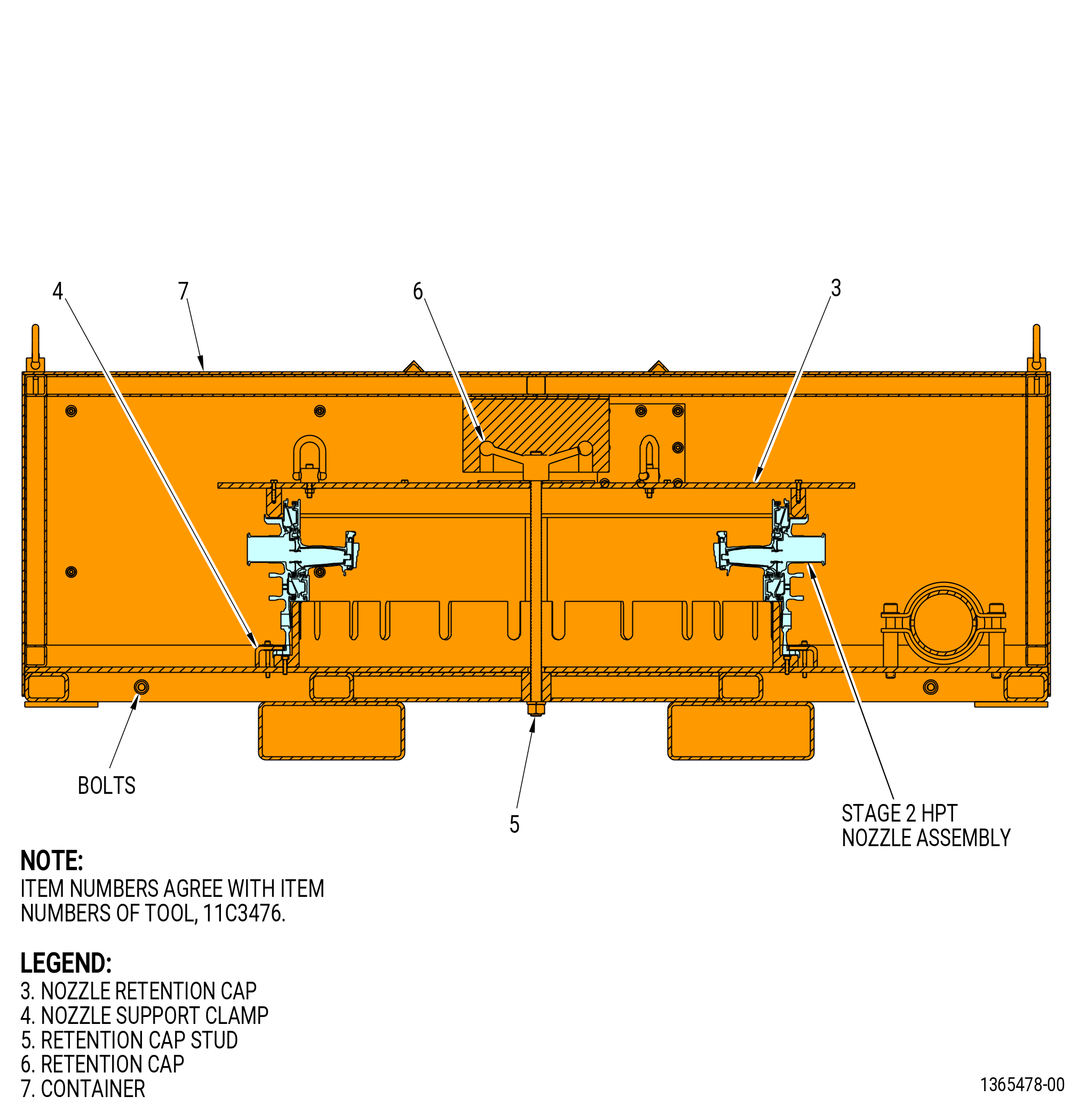
| (5).A. | Alternative Procedure. Install the stage 2 HPT nozzle assembly, aft side up, on the 11C3476 shipping container as follows. Refer to Figure 522. |
| (a) | Attach the three-legged sling to the hoist rings on the container (item 7). |
| WARNING: |
|
| (b) | Remove the container (item 7) from the 11C3476 shipping container. |
| (c) | Remove the retention cap (item 6) and nozzle retention cap (item 3) from the retention cap stud (item 5). |
| (d) | Carefully lower the stage 2 HPT nozzle assembly into the container. Align the holes on the HPT case forward flange with the holes in the 11C3476 shipping container. |
| (e) | Remove the 11C3434 lift/turn fixture from the stage 2 HPT nozzle assembly as follows: |
| 1 | Remove the cap screws (item 6), washers (item 9), and nuts (item 7) that attach the 11C3434 lift/turn fixture to the stage 2 HPT nozzle assembly. Refer to Figure 521. |
| 2 | Remove the 11C3434 lift/turn fixture from the stage 2 HPT nozzle assembly. |
| (f) | Attach the FWD flange of the stage 2 HPT nozzle assembly to the 11C3476 shipping container with nozzle support clamps (item 4). |
| (g) | Align the hole in the nozzle retention cap (item 3) with the retention cap stud (item 5) and lower the nozzle retention cap (item 3) onto the stage 2 HPT nozzle assembly. |
| (h) | Attach the retention cap (item 6) to the retention cap stud (item 5) and tighten the retention cap (item 6). |
| (i) | Attach the three-legged sling to the hoist rings on the container (item 7). |
| WARNING: |
|
| (j) | Lift the container (item 7). |
| (k) | Lower the container (item 7) on the 11C3476 shipping container. |
| (l) | Attach the container (item 7) to the 11C3476 shipping container with four bolts. Tighten the bolts. |
| Subtask 72-50-00-030-083 |
| (6) | Remove the 11C3159 guide from the HPT rotor shaft. Refer to Figure 520. |
| Subtask 72-50-00-030-058 |
| T. | Remove the HPT rotor assembly (34-020 , 72-00-02) (SIN 15000) or (34-021 , 72-00-02) (SIN 15000) from the CDN assembly as follows. |
| (1) | Attach the 11C3056 lift and turn fixture to the HPT rotor assembly as follows. Refer to Figure 523. |
| CAUTION: |
|
| CAUTION: |
|
| (a) | Thread the lift cap (item 2) of the 11C3056 lift and turn fixture on the aft end of the HPT rotor assembly (34-020 , 72-00-02) (SIN 15000) or (34-021 , 72-00-02) (SIN 15000) until the threads are fully engaged. Do not use force to tighten the lift cap. |
| (b) | Connect the lift bar (item 4) of the 11C3056 lift and turn fixture to the lift cap (item 2) in the vertical position with the pin (item 6). |
| (c) | Attach the lift bar (item 4) of the 11C3056 lift and turn fixture to an overhead hoist. |
| CAUTION: |
|
| (d) | Make sure that the hoist is directly above the center of the HPT rotor assembly until you can lift it straight up from the CDN assembly. |
| WARNING: |
|
| (2) | Lift the HPT rotor assembly from the CDN assembly. |
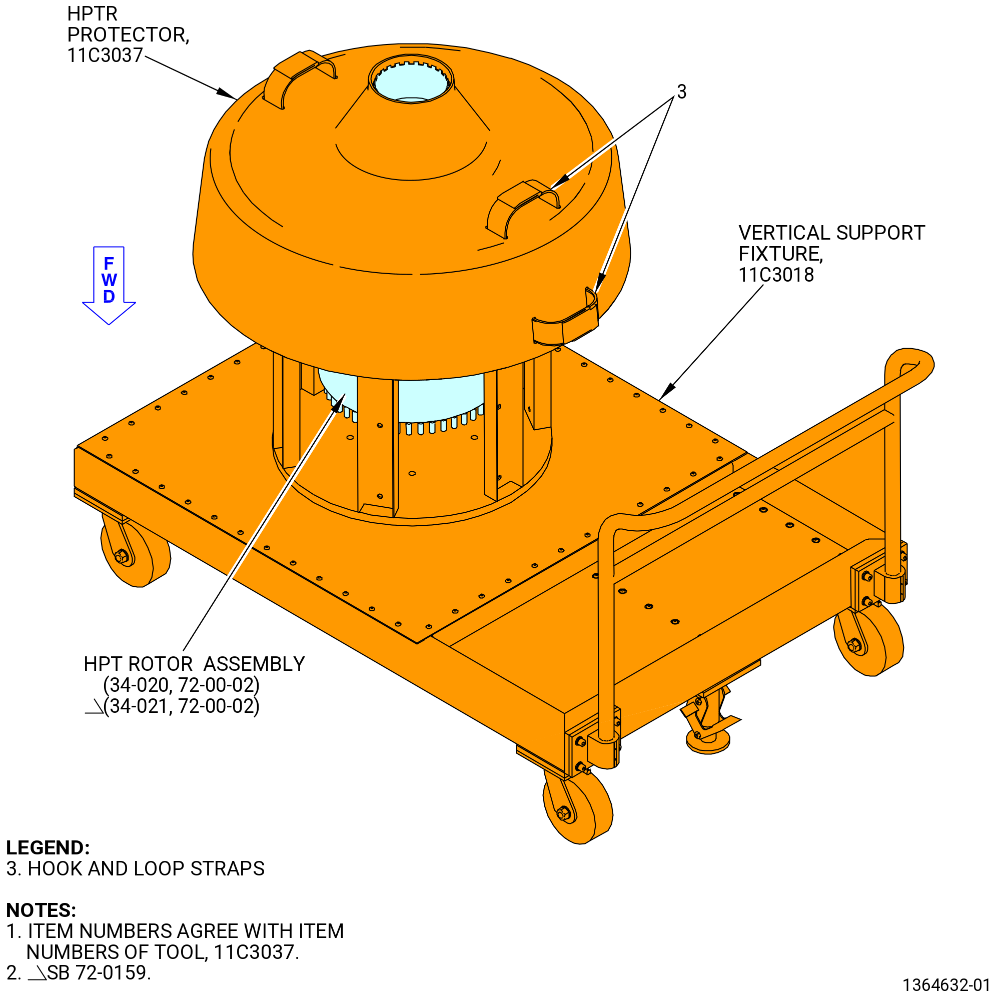
| (3) | Install the HPT rotor assembly on the 11C3018 vertical support fixture or into the 11C4676 shipping container. Refer to Figure 524. |
| (4) | Install the 11C3037 protector . |
| Subtask 72-50-00-030-064 |
| U. | Install the CDN assembly in the 9429M60 roll-over stand as follows: |
| (1) | Remove fixture hardware from froward flange of CDN assembly to disconnect the CDN assembly from the 11C3010 build-up fixture. |
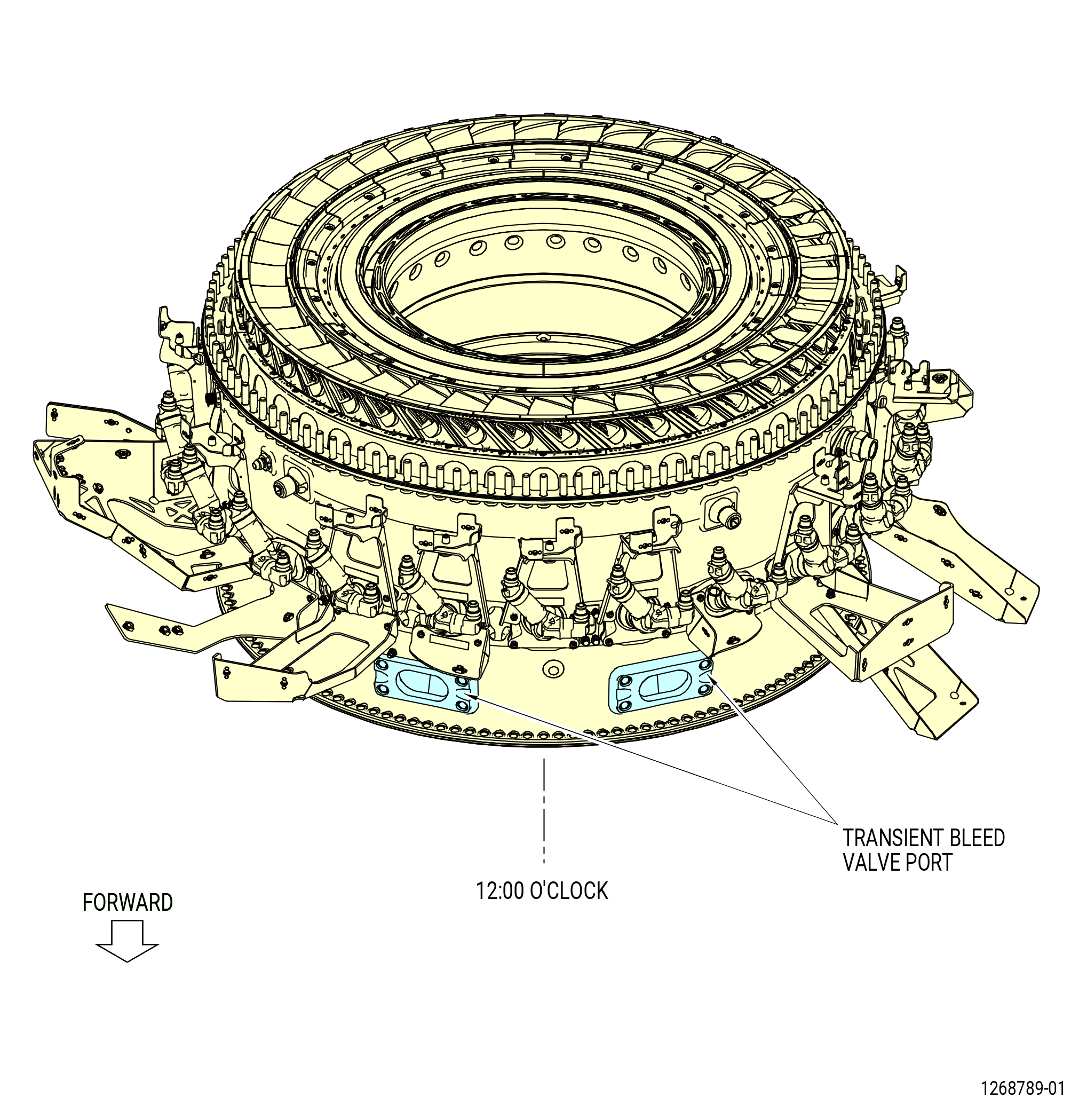
| (2) | Prepare the CDN assembly for installation into the 9429M60 roll-over stand as follows. Refer to Figure 525. |
| (a) | Find the two transient bleed valve ports near the forward flange of the combustion case. The No. 1 fuel nozzle is aligned between the two transient bleed valve ports. Use the C05-003 pen to put a mark on the No. 1 fuel nozzle position. |
| (b) | Use the C05-003 pen to put a mark on the remaining fuel nozzle positions, CW aft looking forward, from fuel nozzle No. 2 thru fuel nozzle No. 22. |
| (c) | Locate the center of the No. 1 fuel nozzle pad. This is the TVCL of the combustion case. Use the C05-003 pen to put a mark on the TVCL on the forward and aft flanges of the combustion case. |
| Subtask 72-50-00-030-072 |
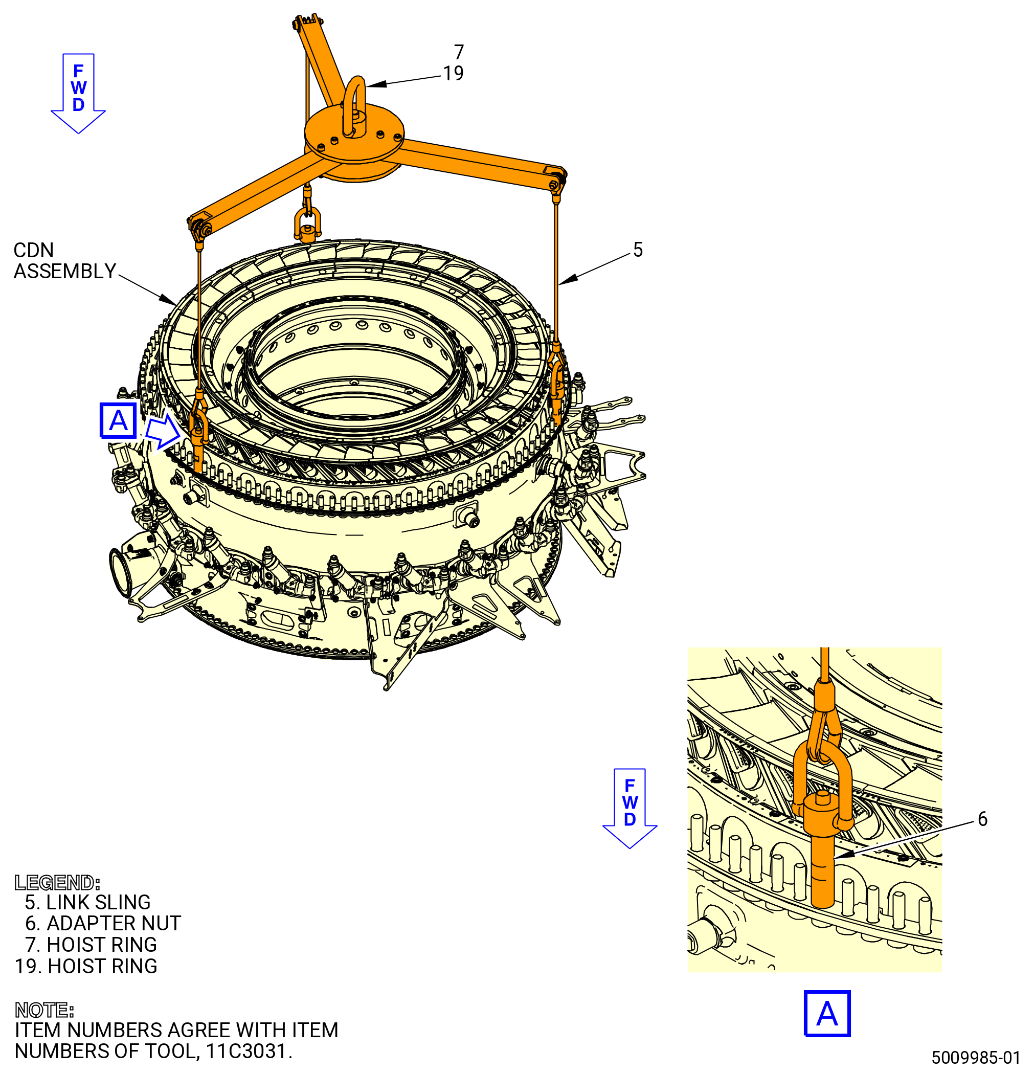
| (3) | Install the 11C3031lift fixture on the CDN assembly aft flange as follows. Refer to Figure 526. |
| NOTE: |
|
| (a) | Attach an overhead hoist to the hoist ring (item 7) or (item 19) and lift the lift fixture above the aft end of the CDN assembly. |
| (b) | Put the 11C3031lift fixture in a position so the link slings (item 5) and adapter nuts (item 6) are directly above three equally spaced bolts in the aft flange of the CDN assembly. |
| (c) | Attach the adapter nuts (item 6) to the bolts in the aft flange of the CDN assembly. |
| (d) | Tighten the adapter nuts (item 6) hand-tight on the bolts in the aft flange of the CDN assembly at three equally spaced locations until fully seated. |
| Subtask 72-50-00-030-073 |
| NOTE: |
|
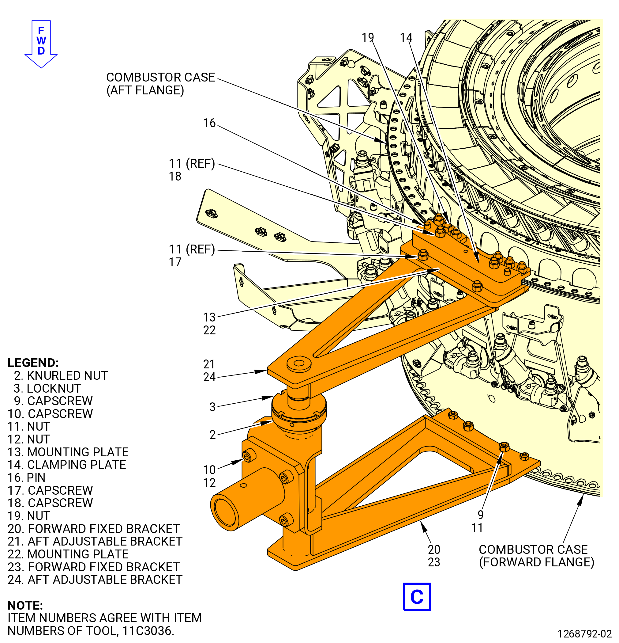
| (4) | Install the 11C3036 bracket set on the combustion case as follows. Refer to Figure 527. |
| (a) | Assemble the 11C3036 bracket set as follows: |
| NOTE: |
|
| 1 | Loosen the locknut (item 3) and turn the knurled nut (item 2) to retract the end plate of the aft adjustable bracket (item 21) or (item 24). |
| 2 | Install the mounting plate (item 13) or (item 22) to the end of the aft adjustable bracket and make sure that the cutouts point out. |
| 3 | Install the capscrews (item 17) through the boltholes in the aft adjustable bracket and mounting plate with the bolt head against the aft adjustable bracket. Install the nuts (item 11) on capscrews and tighten. |
| WARNING: |
|
| (b) | Lift the combustion case with the 11C3031 lift fixture. |
| Subtask 72-50-00-030-074 |
| (c) | Install a bracket set to the combustion case at the 3:00 o'clock position and do as follows: |
| 1 | Align the end plate of the forward fixed bracket (item 20) or (item 23) with the boltholes on the combustion case forward flange at the 3:00 o'clock position. |
| 2 | Move the end plate of the aft adjustable bracket (item 21) or (item 24) to the bolthole on the combustion case aft flange at the 3:00 o'clock position. |
| 3 | Turn the knurled nut (item 2) until the end plates are held tightly against the forward and aft flanges. Make sure that the 3:00 o'clock position marks on the brackets align with TVCL on the combustion case. Make sure that the two pins in the forward fixed bracket (item 20) or (item 23) engage the boltholes in the forward flange of the combustion case. |
| 4 | Turn the locknut (item 3) until it is against the knurled nut (item 2). |
| 5 | Align the boltholes in the clamping plate (item 14) with the alignment pins in the mounting plate (item 13) or (item 22) and the bolts in the combustor case. Install the clamping plate on the mounting plate and make sure that the THIS SIDE UP WITH COMBUSTOR mark points out. |
| 6 | Install the capscrews (item 18) through the boltholes in the bracket, mounting plate, and clamping plate with the bolt head against the aft adjustable bracket. Install the nuts (item 11) on the capscrews and tighten them. |
| 7 | Torque the nuts (item 11) to 70-110 lb in. (7.9-12.4 N.m). |
| 8 | Install the capscrews (item 9) through the boltholes of the forward fixed bracket and the combustion case forward flange with the bolt head against the forward fixed bracket. |
| 9 | Attach the nuts (item 11) to the capscrews (item 9). |
| 10 | Torque the nuts (item 11) to 70-110 lb in. (7.9-12.4 N.m). |
| (d) | Install a bracket set to the combustion case at the 9:00 o'clock position as follows: |
| 1 | Align the end plate of the forward fixed bracket (item 20) or (item 23) with the boltholes on the combustion case forward flange at the 9:00 o'clock position. |
| 2 | Move the end plate of the aft adjustable bracket (item 21) or (item 24) to the bolthole on the combustion case aft flange at the 9:00 o'clock position. |
| 3 | Turn the knurled nut (item 2) until the end plates are held tightly against the forward and aft flanges. Make sure that the 9:00 o'clock position marks on the brackets align with TVCL on the combustion case. Make sure that the two pins in the forward fixed bracket (item 20) or (item 23) engage the boltholes in the forward flange of the combustion case. |
| 4 | Turn the locknut (item 3) until it is against the knurled nut (item 2). |
| 5 | Align the boltholes in the clamping plate (item 14) with the alignment pins in the mounting plate (item 13) or (item 22) and the bolts in the combustor case. Install the clamping plate on the mounting plate and make sure that the THIS SIDE UP WITH COMBUSTOR mark points out. |
| 6 | Install the capscrews (item 18) through the boltholes in the bracket, mounting plate, and clamping plate with the bolt head against the aft adjustable bracket. Install nuts (item 11) on the capscrews and tighten them. |
| 7 | Torque the nuts (item 11) to 70-110 lb in. (7.9-12.4 N.m). |
| 8 | Install the capscrews (item 9) through the boltholes of the forward fixed bracket and the combustion case forward flange with the bolt head against the forward fixed bracket. |
| 9 | Attach the nuts (item 11) to the capscrews (item 9). |
| 10 | Torque the nuts (item 11) to 70-110 lb in. (7.9-12.4 N.m). |
| (5) | Install the combustion case in the 9429M60 roll-over stand as follows. Refer to Figure 527. |
| CAUTION: |
|
| (a) | Lower the floor locks (item 69) of the 9429M60 roll-over stand until they touch the floor. The floor locks must stay in contact with the floor to prevent movement of the roll-over stand. Make sure that the roll-over stand is level. |
| (b) | Turn adapter (item 15) and adapter (item 19) until the edges of the square plates are horizontal and parallel to the floor as follows : |
| 1 | Push the lever (item 24) to unlock the hand wheel (item 31). Turn the hand wheel until the square plates of the adapters are horizontal and parallel to the floor. |
| CAUTION: |
|
| 2 | Release the lever (item 24) to engage the locating plate (item 6) to lock the hand wheel (item 31). |
| NOTE: |
|
| WARNING: |
|
| (c) | Move the combustion case to the 9429M60 roll-over stand. |
| (d) | Align one bracket of the 11C3036 bracket set with the end of the fixed adapter (item 19) of the 9429M60 roll-over stand. |
| (e) | Align the other bracket of the 11C3036 bracket set with the end of the adjustable adapter (item 15) of the 9429M60 roll-over stand. |
| (f) | Install the hardware that attaches the 11C3036 bracket set to the 9429M60 roll-over stand as follows: |
| 1 | Attach the bracket to the fixed adapter (item 19) with the capscrews (item 10) and nut (item 12). |
| 2 | Attach the bracket to the adjustable adapter (item 15) with the capscrews (item 10) and nut (item 12). |
| 3 | Torque the nuts (item 12) to 420-510 lb in. (47.5-57.6 N.m). |
| (6) | Remove the 11C3031lift fixture from the CDN assembly. |