| GENX-1B ENGINE MANUAL | Dated: 03/29/2025 | |
| EM 72-40-00 , ASSEMBLY 001 | ||
| COMBUSTOR DIFFUSER NOZZLE ASSEMBLY - ASSEMBLY 001 - CONFIGURATION 01 | ||
| GENX-1B ENGINE MANUAL | Dated: 03/29/2025 | |
| EM 72-40-00 , ASSEMBLY 001 | ||
| COMBUSTOR DIFFUSER NOZZLE ASSEMBLY - ASSEMBLY 001 - CONFIGURATION 01 | ||
| * * * FOR 1B/P/G03.1B/P/G04.1B/P1/G01 |
| TASK 72-40-00-440-801 |
| 1 . | General. |
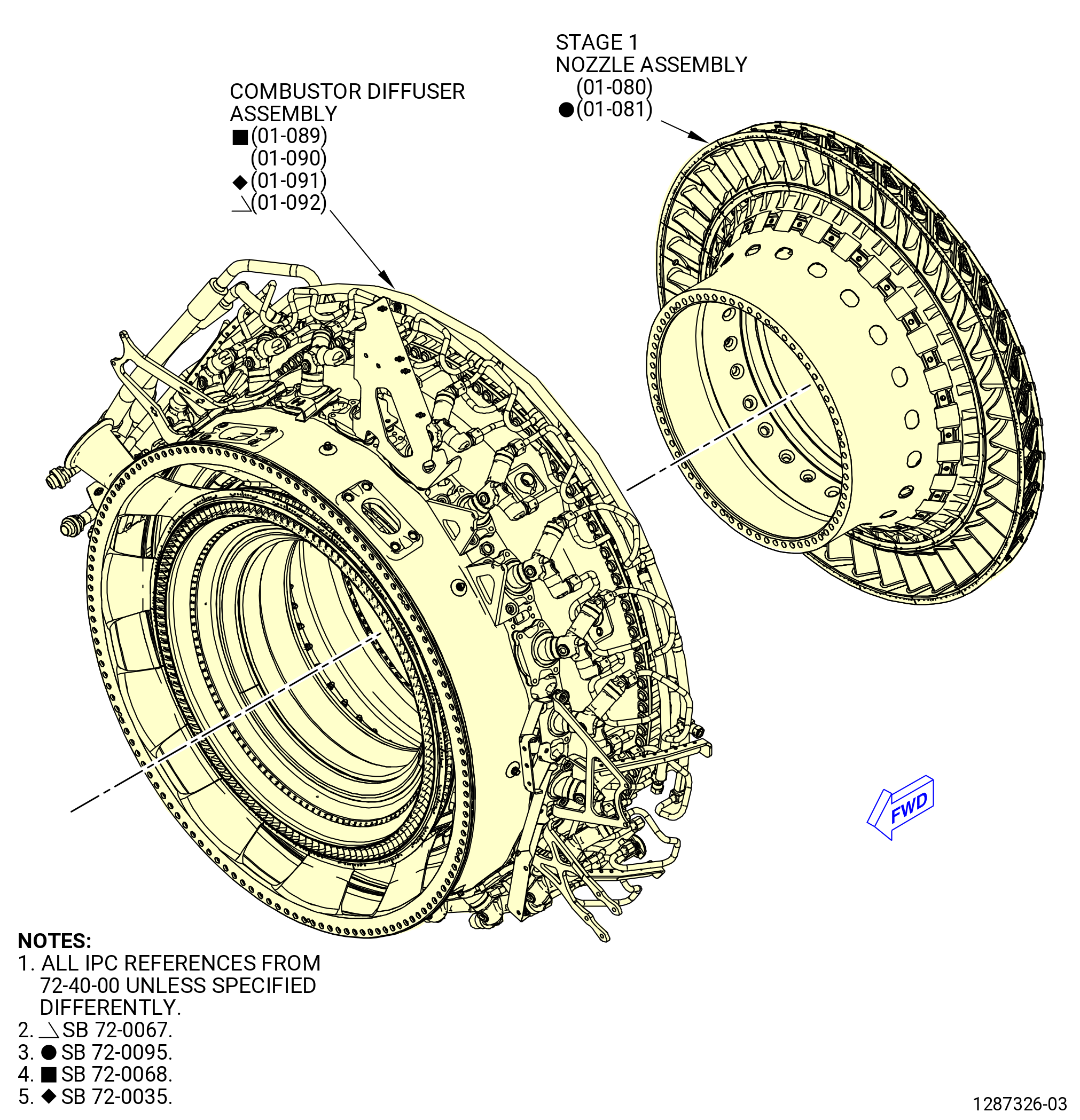
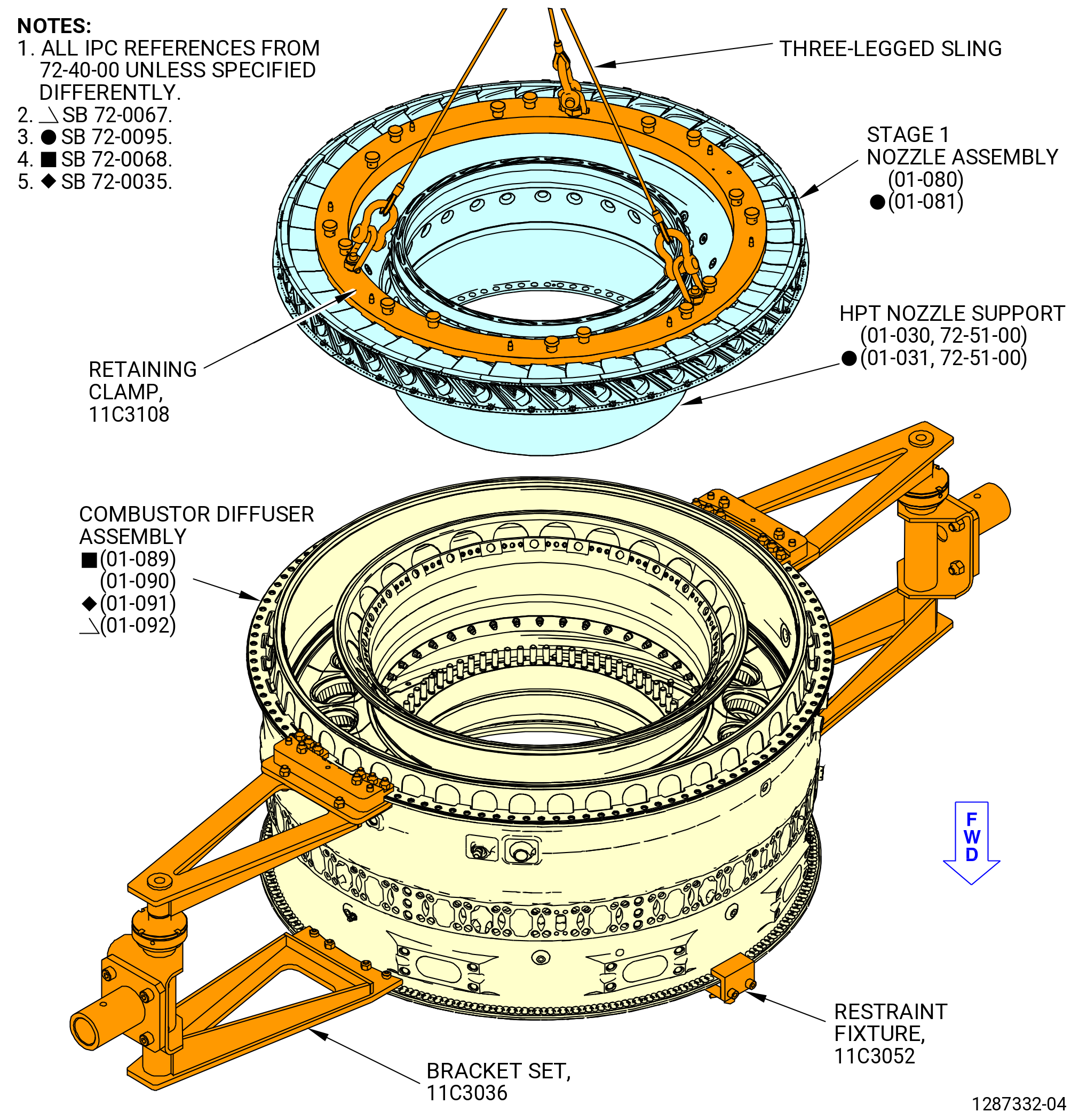
| A. | This procedure gives instructions to assemble the combustor diffuser nozzle (CDN) assembly (33-019 , 72-00-02) (SIN 0010A) or (33-020 , 72-00-02) (SIN 0010A). Refer to Figure 1001. The CDN assembly contains: |
| • |
|
| • |
|
| B. | The combustor diffuser assembly is in the 9429M60 roll-over stand, in the vertical position, aft end up, with the 11C3052 restraint fixture and the 11C4297 pad covers installed. |
| C. | The stage 1 nozzle assembly is on the 11C3081 buildup fixture in the vertical position, aft end up. |
| D. | Install all of the bolts with the heads up or forward unless specified differently. |
| E. | Apply the lubricants to the threads and the friction surfaces only. |
| F. | Make sure that all rabbets and flanges are free of foreign material and raised metal. |
| G. | Follow the instructions to safety parts with safety wire, safety cable, cotter pins, or tab washers. Refer to TASK 70-11-00-400-001 (FASTENER RETENTION PROCEDURES) . |
| 2 . | Tools, Equipment, and Materials. |
| NOTE: |
|
| A. | Tools and Equipment. |
| (1) | Special Tools. |
| (2) | Standard Tools and Equipment. |
|
| (3) | Locally Manufactured Tools. None. |
| B. | Consumable Materials. |
|
| C. | Referenced Procedures. |
|
| D. | Expendable Parts. |
|
| 3 . | Procedure. |
| Subtask 72-40-00-440-001 |
| A. | Make sure that the combustor diffuser assembly (01-089) (SIN 12000) or, (01-090) (SIN 12000) or, (01-091) (SIN 12000), or (01-092) (SIN 12000) is correctly installed in the 9429M60 roll-over stand with the 11C3052 restraint fixture installed. If the 9429M60 roll-over stand is not available, the CDN can be assembled in the 11C4578 assembly stand. |
| NOTE: |
|
| Subtask 72-40-00-440-002 |
| WARNING: |
|
| B. | Clean the mating surfaces of these components with C04-002 stoddard solvent, C04-035 isopropyl alcohol, or 50-50 blend of C04-035 isopropyl alcohol, and C04-228 denatured alcohol: |
| • |
|
| • |
|
| • |
|
| Subtask 72-40-00-440-021 |
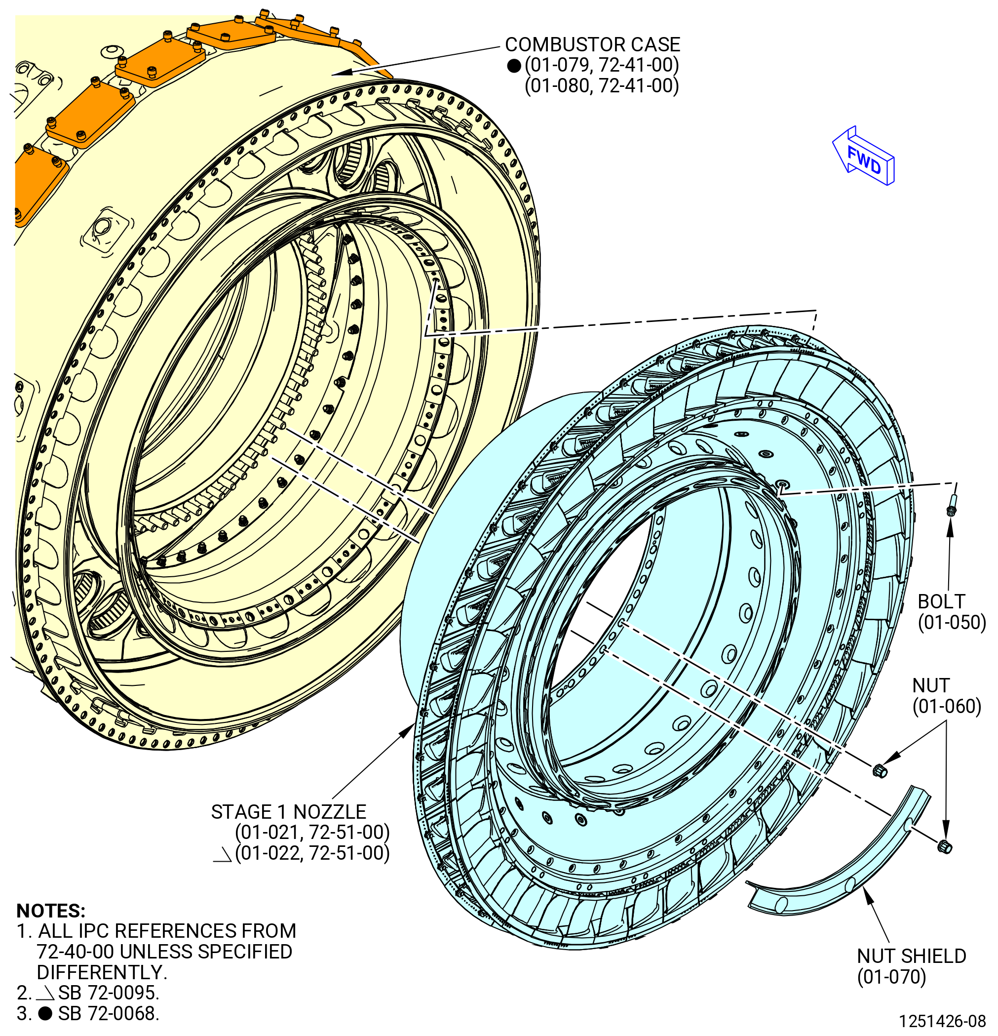
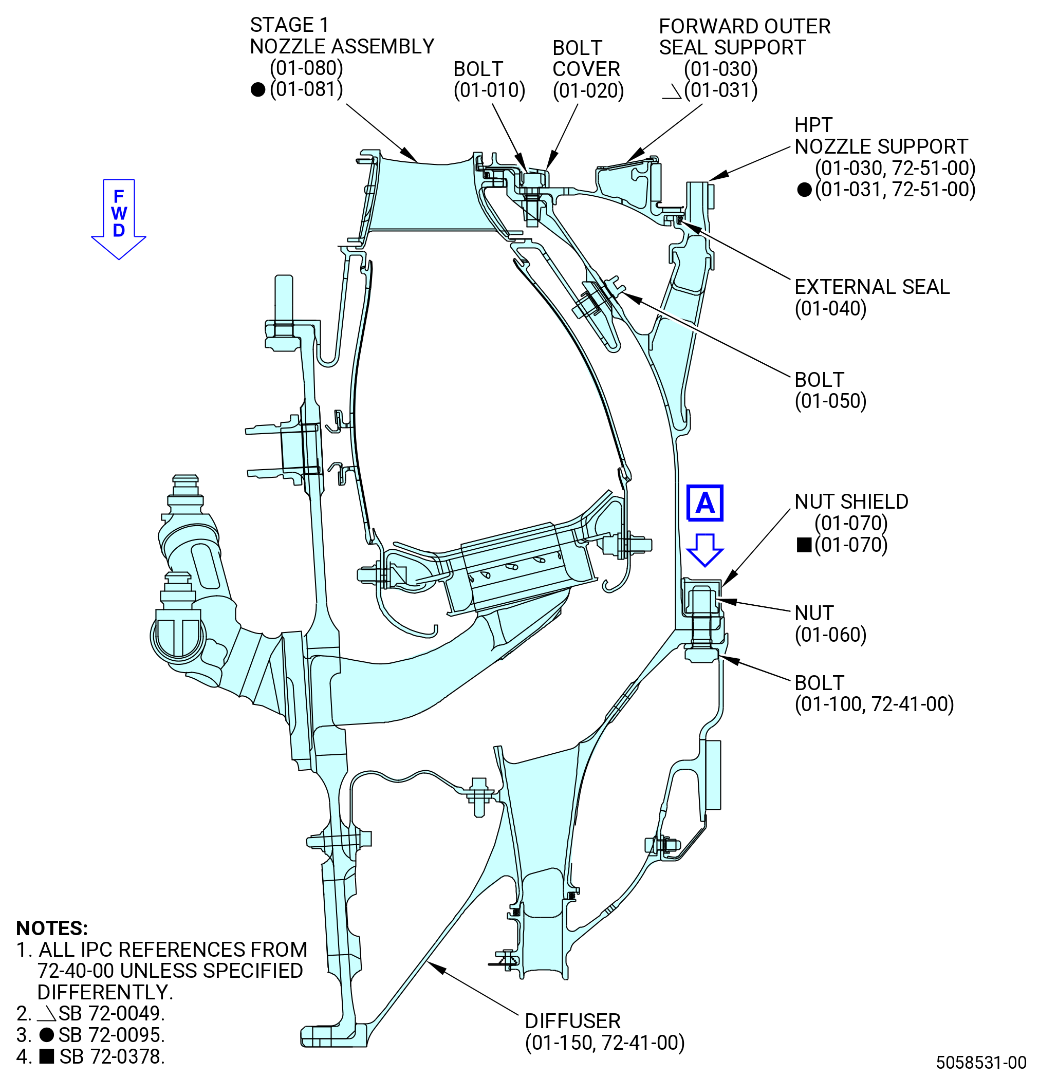
| C. | Install the stage 1 nozzle assembly (01-080) (SIN 17200) or (01-081) (SIN 17200) as follows. Refer to Figure 1002. |
| (1) | Do an inspection of the self-locking shank nut (P/N 9114M97P19 ) internal thread condition for damaged thread, flatten thread, and worn or missing thread. If one of the conditions is observed, replace the shank nuts into a new one before the assembly on the combustor diffuser nozzle assembly. Refer to TASK 72-00-00-800-819 (72-00-00, SPECIAL PROCEDURE 016) or refer to TASK 72-51-01-300-801 (72-51-01, REPAIR 001). |
| (2) | Remove the slave nuts and washers from the outlet guide vane (OGV) bolts. |
| (3) | Put a small bead of C10-154 beeswax every two to three inches on the aft outer surface of the combustor case (12001). |
| NOTE: |
|
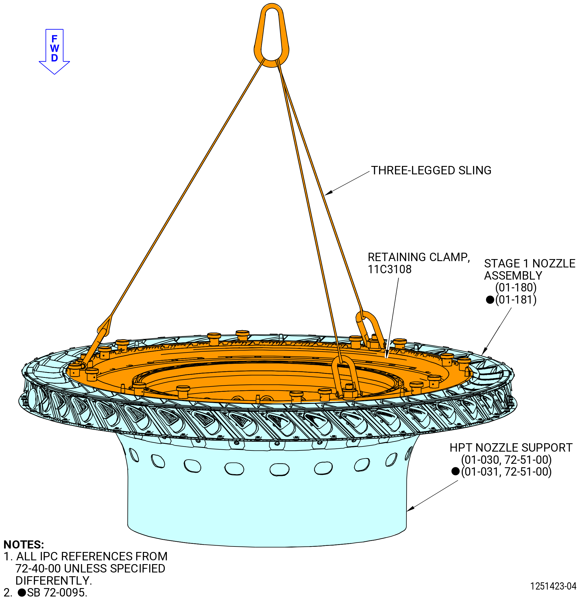
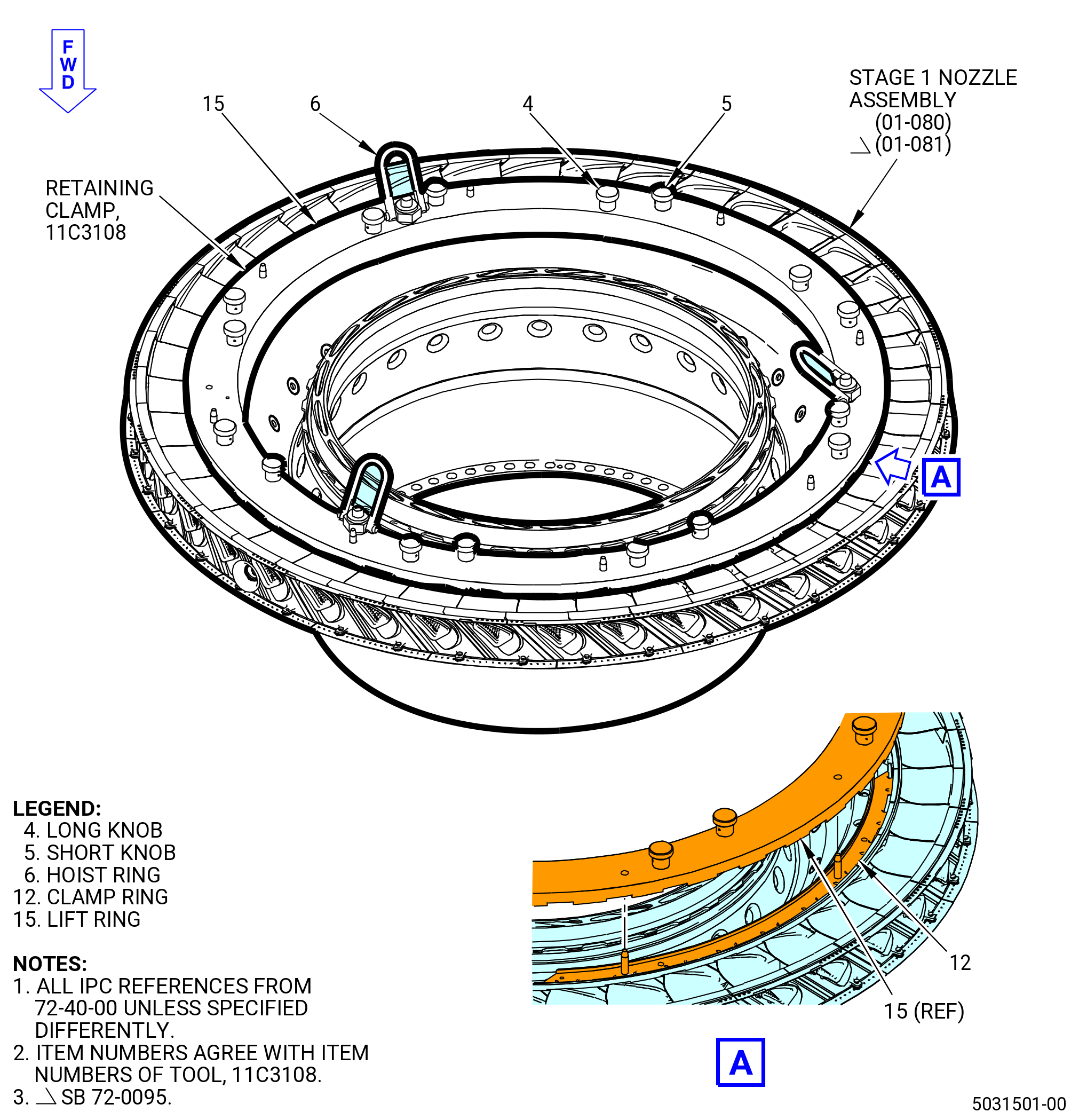
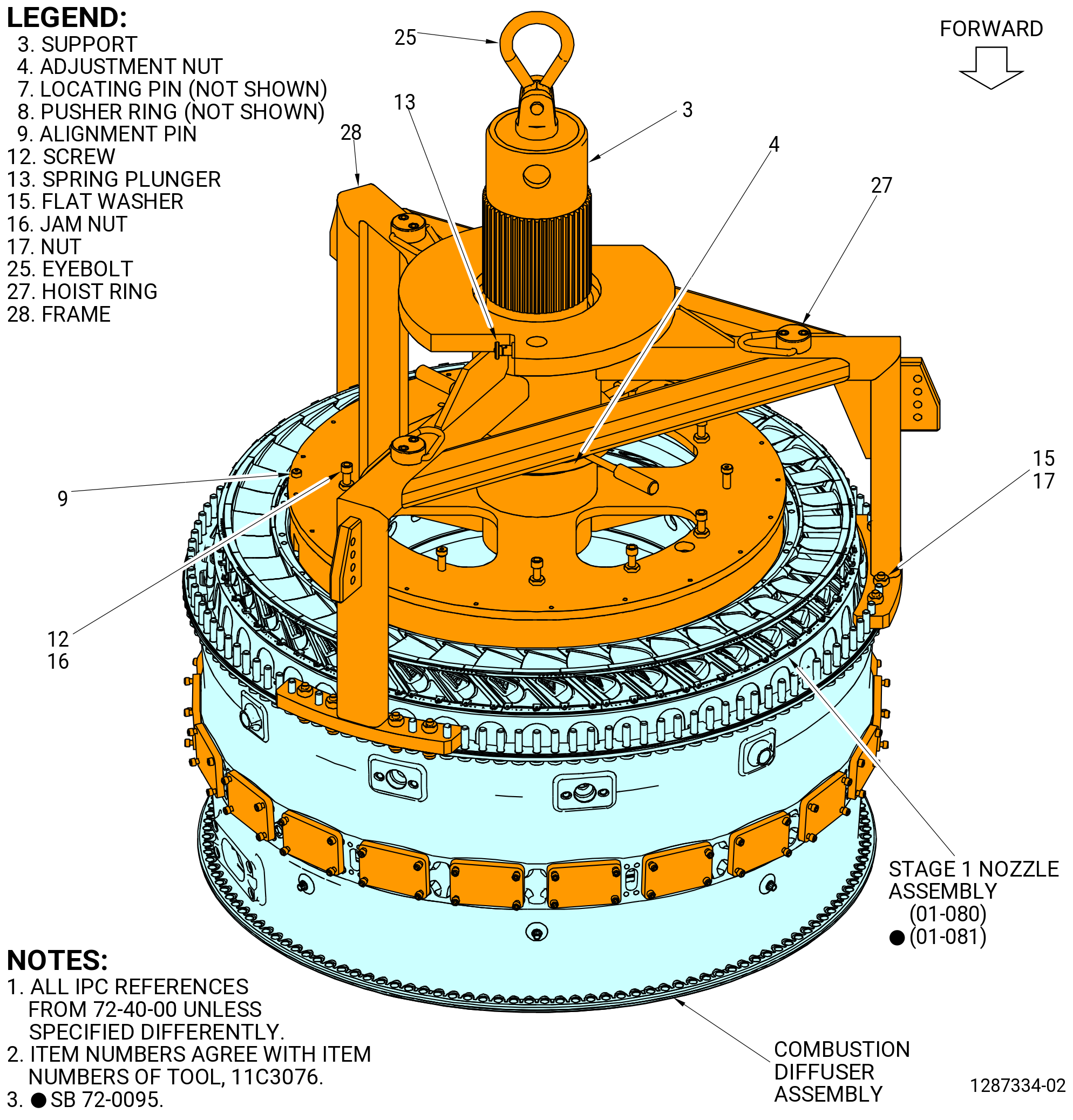
| (4) | Attach the 11C3108 retaining clamp to the stage 1 nozzle assembly (01-080) (SIN 17200) or (01-081) (SIN 17200) as follows. Refer to Figure 1002. |
| (a) | Put one clamp ring (item 12) with the top vertical centerline (TVCL) marking at the TVCL position on the stage 1 nozzle assembly. Engage the tabs in the clamp ring in the slots in the inner band of the nozzles. If necessary, tap the clamp ring down and radially outward to make sure that the clamp ring engages in the slots. |
| (b) | Install the remaining three clamp rings (item 12) on the stage 1 nozzle assembly. Engage the tabs in the clamp rings in the slots in the inner band of the nozzles. If necessary, tap the clamp rings down and radially outward to make sure that the clamp rings engage in the slots. |
| (c) | Attach a three-legged sling to the hoist rings (item 6) of the lift ring (item 15). |
| (d) | Put the lift ring (item 15) on the clamp rings (item 12). Align the TVCL of the lift ring with the TVCL of the stage 1 nozzle assembly. |
| (e) | Make sure that the pins of the clamp ring align with the holes in the lift ring. |
| (f) | Make sure that the long knobs (item 4) align with the holes in the nut plate and the short knobs (item 5) align with the holes in the clamp rings. |
| (g) | Tighten the long knobs (item 4) and the short knobs (item 5) to attach the lift ring to the clamp rings and the stage 1 nozzle support. |
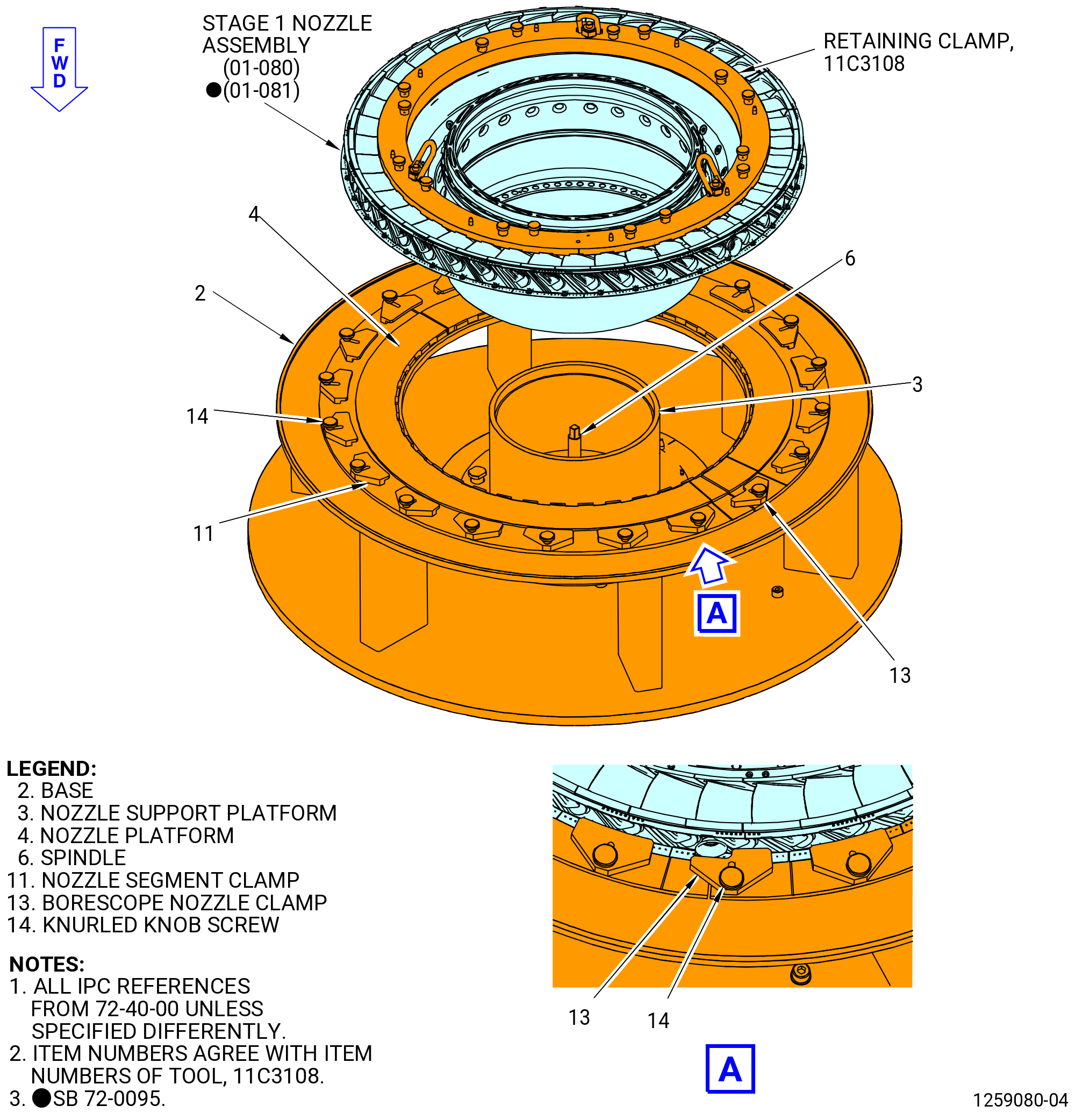
| (5) | Loosen screws (item 14) of the 11C3081 build-up fixture and move the nozzle segment clamps (item 11) and borescope nozzle clamp (item 13) away from nozzle segments. Refer to Figure 1003. |
| (6) | Attach a three-legged sling to the hoist rings (item 6) of the 11C3108 retaining clamp. |
| Subtask 72-40-00-440-030 |
| WARNING: |
|
| (7) | Lift the stage 1 nozzle assembly (01-080) (SIN 17200) or (01-081) (SIN 17200) and put it in position above the combustor case rear flange (12001). Refer to Figure 1004. |
| (8) | Use a white light and pick to make sure that all the inboard and outboard spline seals are installed between the nozzle segments. Refer to Figure 1005. |
| (9) | Align the middle of the No. 1 vane in the stage 1 nozzle with the TVCL of the combustor case. Make sure that the stage 1 nozzle borescope hole is at the 3:00 o'clock position, aft looking forward (ALF). |
| (10) | Lower the stage 1 nozzle assembly to the combustor assembly and align the bolts in the diffuser/stage 10 OGV flange with the boltholes in the stage 1 nozzle support flange. |
| (11) | Make sure that all shear bolts (bolts) (01-100 , 72-41-00) (SIN 17221) can be moved freely without binding. |
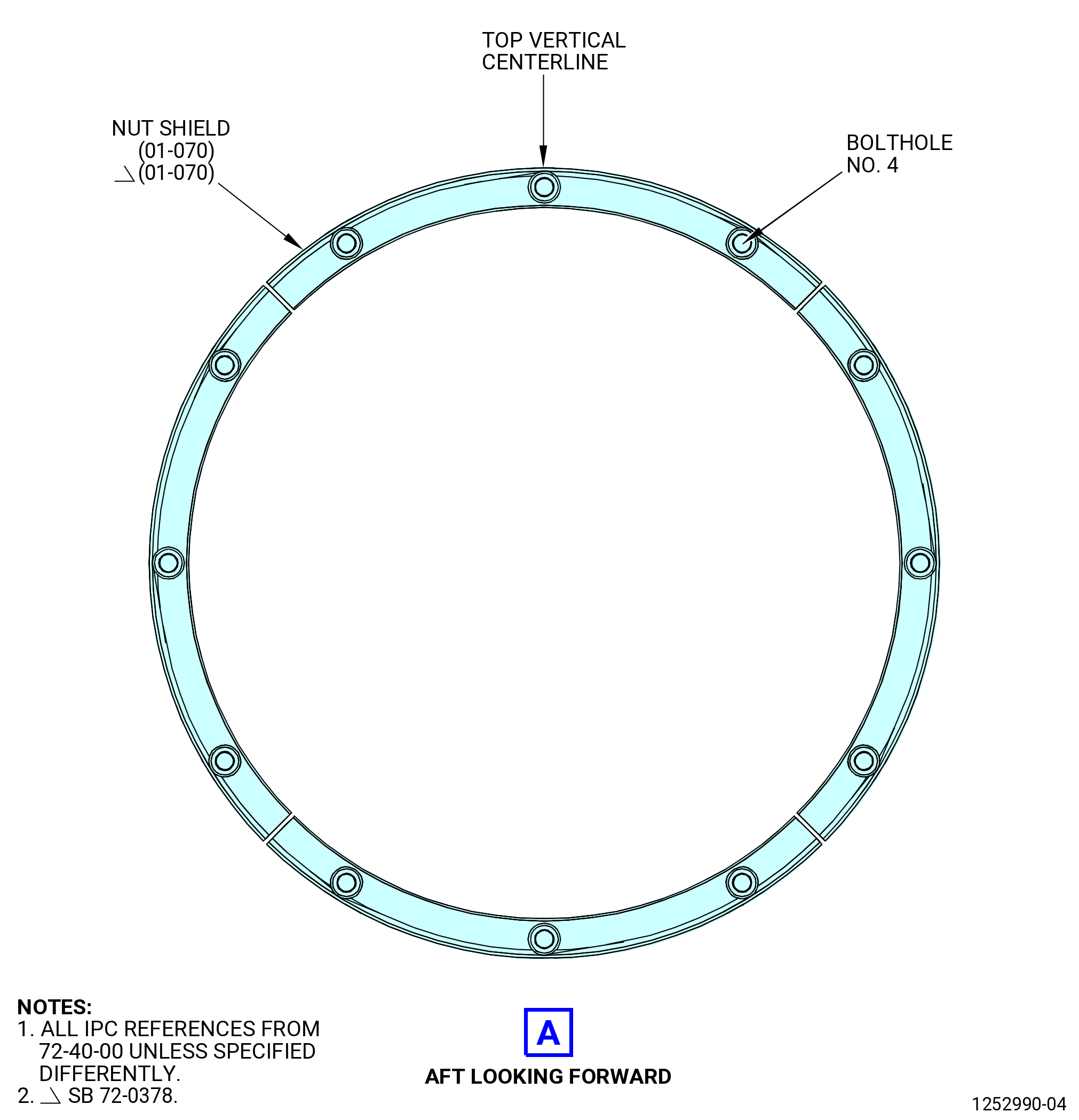
| (12) | Temporarily install the four nut shields (01-070) (SIN 17204) equally spaced on the bolts (17221). Use the C05-003 pen to put a mark on the bolts that you can see and then remove the nut shields. |
| WARNING: |
|
| (13) | Apply C02-058 lubricant or C02-097 lubricant to the threads and friction surfaces of eight self-locking nuts (nuts) (01-060) (SIN 17240). Refer to Figure 1006. |
| (14) | Install eight equally spaced nuts (01-060) (SIN 17240) on bolts (01-100 , 72-41-00) (SIN 17221) that do no have a mark, to seat the stage 1 nozzle assembly (01-080) (SIN 17200) or (01-081) (SIN 17200) to the combustor diffuser assembly. |
| NOTE: |
|
| (15) | Torque the nuts (01-060) (SIN 17240) to 251 to 295 lb in. (28.4 to 33.3 Nm) to seat the stage 1 nozzle on the combustor diffuser assembly. |
| WARNING: |
|
| CAUTION: |
|
| (16) | Install the HPT nozzle to the combustor. Apply C02-058 lubricant or C02-097 lubricant to the threads and friction surfaces of 25 bolts (01-050) (SIN 12420). Refer to Figure 1006. |
| (17) | Install the 25 bolts (01-050) (SIN 12420) through the stage 1 nozzle assembly (01-030 , 72-51-00) (SIN 172A1) or (01-031 , 72-51-00) (SIN 172A1) into the combustor assembly (01-090 , 72-41-00) (SIN 12400) or (01-091 , 72-41-00) (SIN 12400) and tighten them. |
| (18) | Torque the bolts (12420) at equally spaced locations to 69-81 lb in. (7.8-9.2 N.m) in a criss-cross pattern. |
| (19) | Apply a final torque of 69-81 lb in. (7.8-9.2 N.m) to all the bolts (12420) in a circular pattern. |
| (20) | Remove the 11C3108 retaining clamp as follows: |
| (a) | Fully loosen the long knobs (item 4) and the short knobs (item 5). |
| (b) | Remove the lift ring (item 15) from the stage 1 nozzle assembly. |
| (c) | Remove the clamp rings (item 12). |
| WARNING: |
|
| (21) | Apply C02-058 lubricant or C02-097 lubricant to the threads and friction surfaces of the remaining 48 nuts (01-060) (SIN 17240). |
| (22) | Install the 48 nuts (01-060) (SIN 17240) on every bolt (01-100 , 72-41-00) (SIN 17221) except the ones previously marked and tightened. |
| (23) | Torque the nuts (01-060) (SIN 17240) in a criss-cross pattern to 251 to 295 lb in. (28.4 to 33.3 Nm). |
|
|
| Subtask 72-40-00-440-040 |
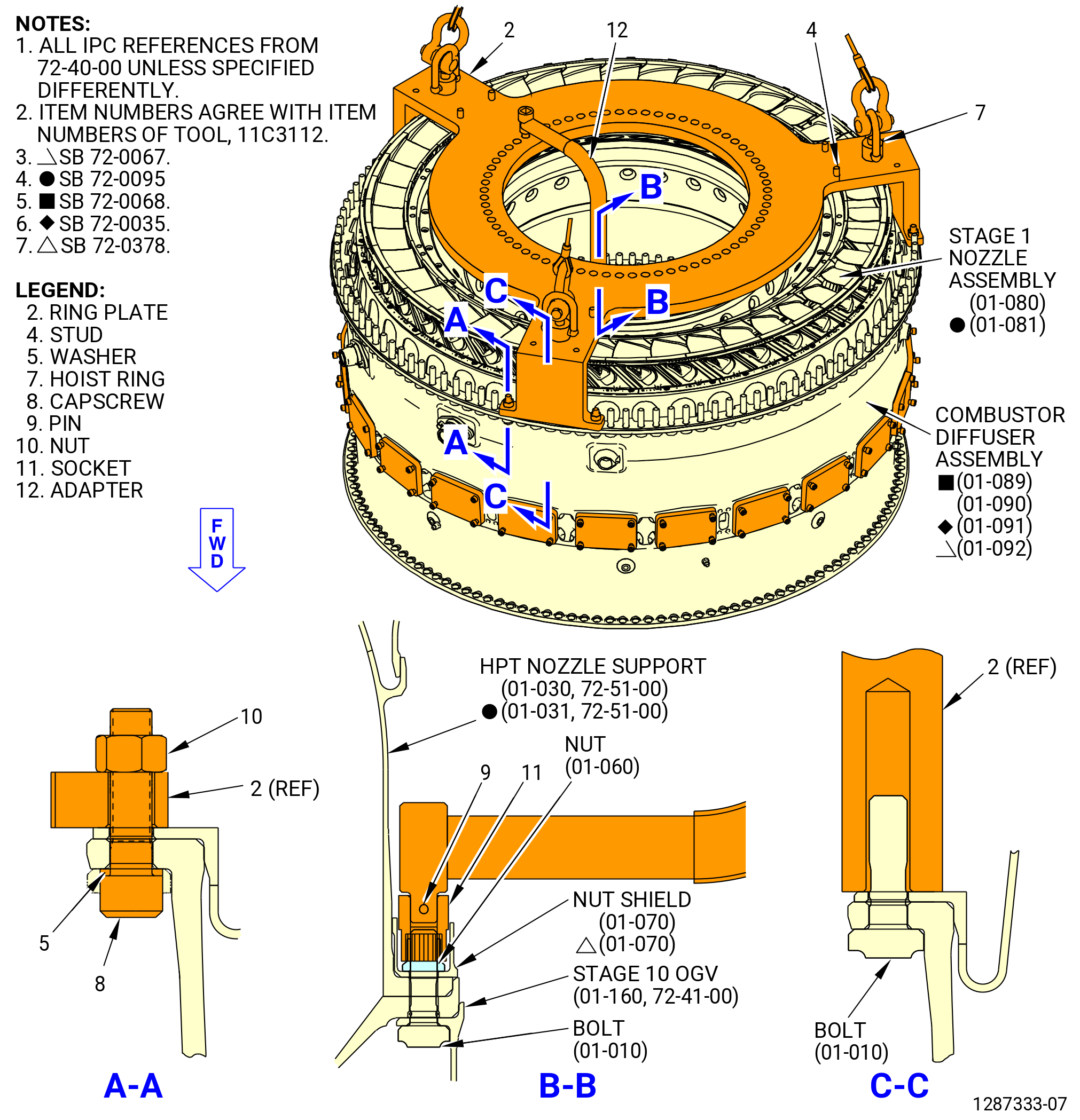
| D. | Torque the stage 1 nozzle assembly nuts (01-060) (SIN 17240) and install the nut shields (01-070) (SIN 17204). Refer to Figure 1007 and do as follows: |
| WARNING: |
|
| (1) | Attach a three-legged sling to the hoist rings (item 7) of the 11C3112 torque fixture. |
| (2) | Align the TVCL on the ring plate (item 2) with the TVCL of the combustor case (12001). |
| (3) | Lower the 11C3112 torque fixture on to the combustor case (12001). Make sure that the legs of the ring plate (item 2) engage the bolts in the combustor case (12001) aft flange. |
| (4) | Attach the ring plate (item 2) to the combustor case (12001) with capscrews (item 8), nuts (item 10) and washers (item 5). |
| (5) | Insert the adapter (item 12), with the socket (item 11) end, through the center opening in the adapter ring (item 2). |
| (6) | Put the bar on the aft end of the adapter in one of the 56 holes on the ring plate (item 2). |
| (7) | Deleted. |
| (8) | Use the adapter (item 12) of the 11C3112 torque fixture and torque the nuts (01-060) (SIN 17240) in a criss-cross pattern. |
| (9) | Torque all 56 installed nuts (01-060) (SIN 17240) in a criss-cross pattern to 336 to 394 lb in. (38.0 to 44.5 Nm). |
| (10) | Loosen and torque one nut (01-060) (SIN 17240) at a time in a circular pattern to 336 to 394 lb in. (38.0 to 44.5 Nm) until all of the 56 nuts are torqued twice. |
| (11) | Deleted. |
| (12) | Install the four nut shields (01-070) (SIN 17204) as follows. Refer to Figure 1008. |
| WARNING: |
|
| (a) | Apply C02-058 lubricant or C02-097 lubricant to the threads and friction surfaces of the remaining 12 nuts (01-060) (SIN 17240). |
| (b) | Put the four nut shields (01-070) (SIN 17204) on the 12 bolts (01-100 , 72-41-00) (SIN 17221) previously marked. |
| (c) | Install 12 nuts (01-060) (SIN 17240) on the bolts (17221) and tighten them in a criss-cross pattern. |
| (d) | Torque the nuts (01-060) (SIN 17240) in a criss-cross pattern to 336 to 394 lb in. (38.0 to 44.5 Nm). |
| (e) | Loosen and torque one nut (01-060) (SIN 17240) at a time in a circular pattern to 336 to 394 lb in. (38.0 to 44.5 Nm) until all the nuts are torqued twice. |
| (f) | Deleted. |
| Subtask 72-40-00-440-023 |
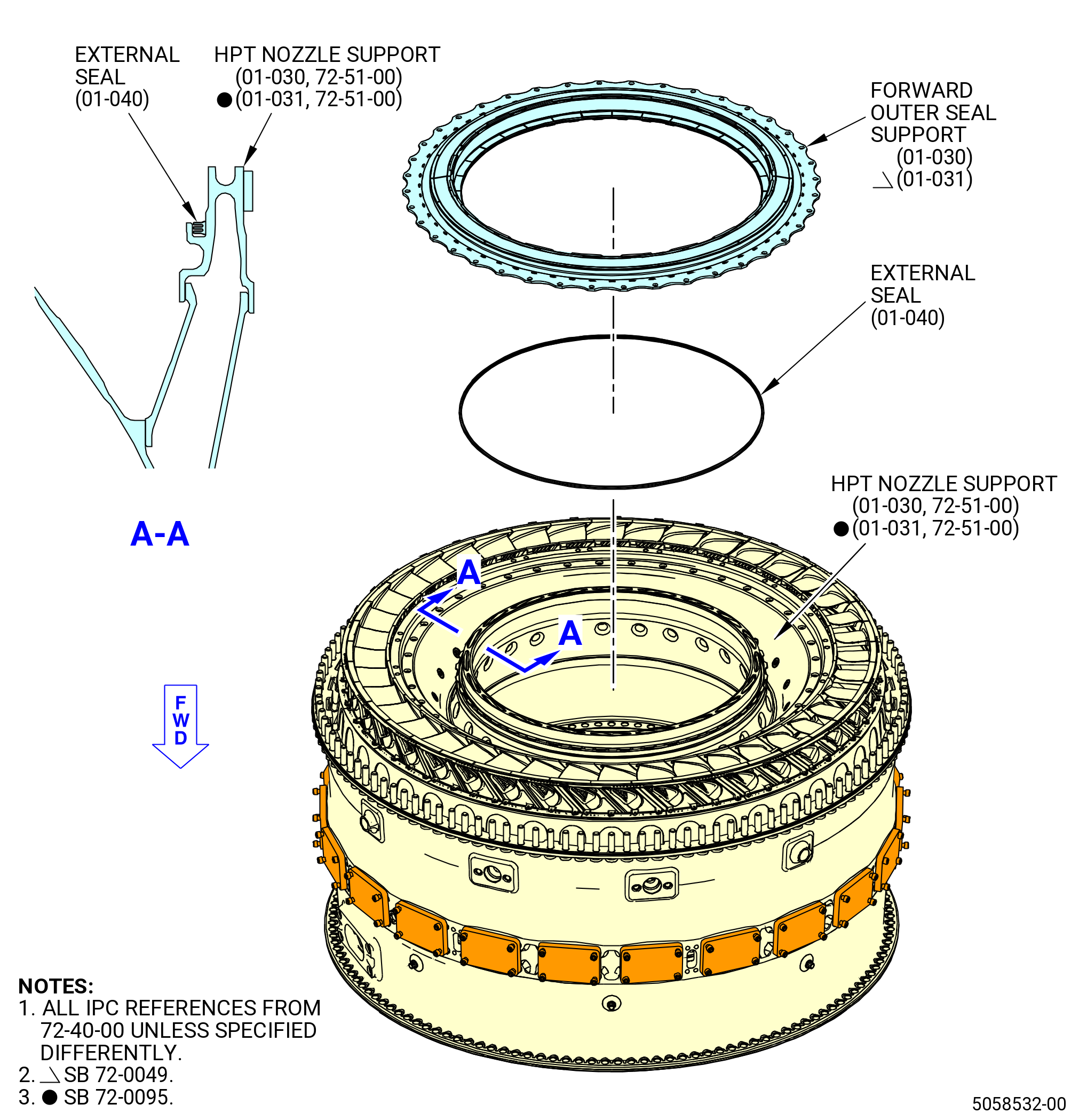
| E. | Install the HPT forward outer seal support (forward outer seal support) (01-030) (SIN 172A4) or (01-031) (SIN 172A4) as follows. Refer to Figure 1009. |
| WARNING: |
|
| WARNING: |
|
| (1) | Clean the forward outer seal support with C04-002 Stoddard solvent, C04-035 isopropyl alcohol, or 50-50 blend of C04-035 isopropyl alcohol, and C04-228 denatured alcohol. |
| WARNING: |
|
| (2) | Decrease the temperature of the forward outer seal support as follows: |
| (a) | Apply dry ice equally to the forward outer seal support for 15 minutes. |
| (3) | Install the external seal (01-040) (SIN 172N1) in the HPT nozzle support (01-030 , 72-51-00) (SIN 172A1) or (01-031 , 72-51-00) (SIN 172A1). |
| (4) | Put the forward outer seal support on the HPT nozzle support (01-030 , 72-51-00) (SIN 172A1) or (01-031 , 72-51-00) (SIN 172A1). Align the TOP mark on the forward outer seal support with the top vertical center line of the combustor case (12001) and the HPT nozzle support (01-030 , 72-51-00) (SIN 172A1) or (01-031 , 72-51-00) (SIN 172A1). |
| (5) | Push the forward outer seal support until the bolthole flange is against the forward inner nozzle support. |
| NOTE: |
|
| Subtask 72-40-00-440-033 |
| F. | Engage the forward outer seal support (01-030) (SIN 172A4) or (01-031) (SIN 172A4) and the HPT nozzle support (01-030 , 72-51-00) (SIN 172A1) or (01-031 , 72-51-00) (SIN 172A1) bayonet tabs as follows. Refer to Figure 1010. |
| (1) | Remove the slave washers and nuts from the combustor case aft flange bolts. |
| WARNING: |
|
| (2) | Attach the three-legged sling to the hoist rings (item 27) of the 11C3076 remove/install fixture. Use a hoist to remove the frame (item 2) from the support (item 3). |
| (3) | Turn the screws (item 12) to fully retract the pusher ring (item 8). |
| (4) | Turn the adjustment nut (item 4) until it makes contact with the machined surface on the support (item 3). |
| (5) | Attach a hoist to the eyebolt (item 25) and lift the support (item 3) above the forward outer seal. |
| (6) | Align the locating pins (item 7) with the boltholes in the forward outer seal. |
| (7) | Lower the support (item 3) onto the forward outer seal and engage the locating pins (item 7) in the boltholes. Look through the cutouts in the support to make sure that the support is completely against the forward outer seal and all of the locating pins are engaged in the boltholes. |
| (8) | Remove the hoist from the eyebolt (item 25). |
| (9) | Attach the three-legged sling to the hoist rings (item 27) of the frame (item 2). Use a hoist and lift the frame above the support (item 3). |
| (10) | Lower the frame (item 2) on the support (item 3) with the bolts in the combustor case flange in the boltholes in the legs of the frame. |
| CAUTION: |
|
| (11) | Attach the frame (item 28) to the combustor case with 12 nuts (item 17) and flat washers (item 15). |
| (12) | Remove the three-legged sling from the hoist rings (item 27). |
| (13) | Turn the adjusting nut (item 4) until it is against the frame (item 28). |
| (14) | Turn the jam nuts (item 16) on the screws (item 12) to put them away from the support (item 3). |
| (15) | Turn the capscrews (item 12) until the pusher ring (item 8) touches the forward outer seal. |
| (16) | Use a depth gage at the three holes in the support (item 3) and measure the distance from the top of the support (item 3) to the top of the pusher ring (item 8). Use this dimension as a reference to determine the correct amount of deflection in the subsequent step. |
| (17) | Turn each capscrew (item 12) one-quarter turn at a time to deflect the forward outer seal until the depth from the top of the support (item 3) to the top of the pusher ring (item 8) is 0.010 inch (0.25 mm) more than the reference dimension in the previous step. |
| (18) | Turn the jam nuts (item 16) tight against the support (item 3). |
| (19) | Install the Sweeney No. 8200 torque multiplier on the 11C3076 remove/install fixture. Engage the two anchor pins in the holes in the frame (item 2) and engage the spring plungers (item 13). |
| (20) | Attach a three-quarter inch drive breaker bar to the torque multiplier. |
| (21) | Turn the torque multiplier to engage the forward outer seal support (01-030) (SIN 172A4) or (01-031) (SIN 172A4) and the HPT nozzle support (01-030 , 72-51-00) (SIN 172A1) or (01-031 , 72-51-00) (SIN 172A1) bayonet tabs as follows: |
| (a) | Turn the torque multiplier to turn the forward outer seal support counterclockwise (CCW), ALF. |
| (b) | Turn the forward outer seal until the scribe lines in the cutouts of the support (item 3) align with the boltholes in the forward inner nozzle support. |
| (c) | Use the threaded alignment pins (item 9) at the alignment holes located between the scribed lines in the support to make sure that the forward outer seal and the forward inner nozzle support are aligned. The threads of the alignment pins must freely engage the threads of the boltholes. |
| (d) | Remove the threaded alignment pins (item 9). |
| (22) | Disengage the spring plungers (item 13) from the pins of the torque multiplier. |
| (23) | Use a hoist to remove the torque multiplier from the install/remove fixture. |
| (24) | Remove the nuts (item 17) and flat washers (item 15). |
| (25) | Attach a hoist to the eyebolt (item 25) and remove the 11C3076 remove/install fixture. |
| Subtask 72-40-00-440-026 |
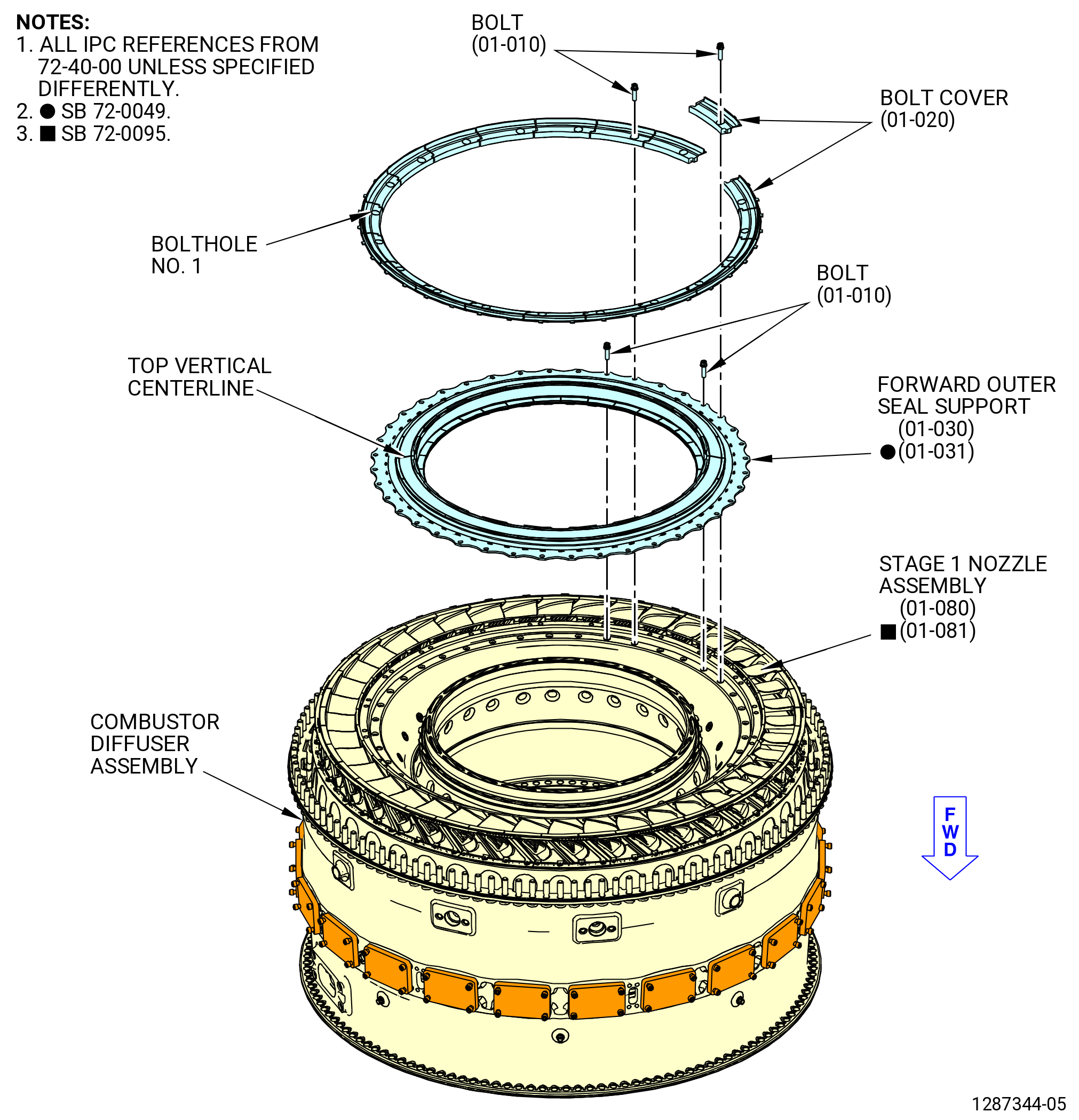
| G. | Attach the forward outer seal support (01-030) (SIN 172A4) or (01-031) (SIN 172A4) on the stage 1 nozzle assembly (01-080) (SIN 17200) or (01-081) (SIN 17200) as follows. Refer to Figure 1011. |
| WARNING: |
|
| (1) | Apply C02-058 lubricant or C02-097 lubricant to the threads and friction surfaces of the 20 bolts (01-010) (SIN 17222). |
| (2) | Find the number 1 hole at the first hole to the right of TVCL. |
| (3) | Start at hole number 2 and install bolts (17222) in 20 equally spaced holes. Hand tighten the bolts. |
| NOTE: |
|
| (4) | Torque four bolts (17222) equally spaced in a criss-cross pattern to 85 lb in. (9.6 N.m.) to seat the forward outer seal. |
| (5) | Torque the 20 installed bolts (01-010) (SIN 17222) in a criss-cross pattern to 106 to 124 lb in. (12.0 to 14.0 Nm.). |
| Subtask 72-40-00-440-034 |
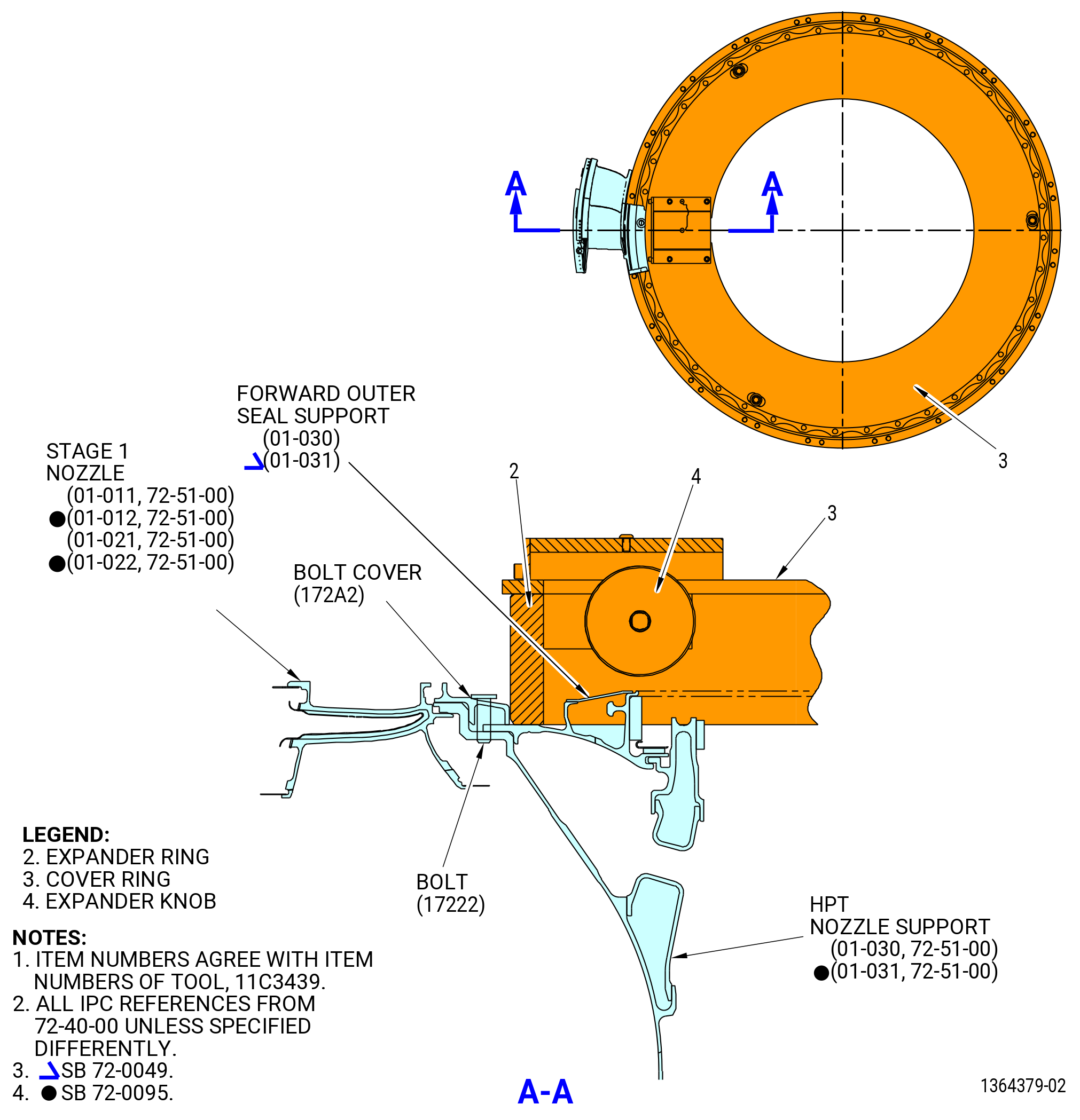
| H. | Install the bolt covers (172A2) as follows. Refer to Figure 1011 and Figure 1012. |
| WARNING: |
|
| (1) | Apply C02-058 lubricant or C02-097 lubricant to the threads and friction surfaces of the 20 bolts (01-010) (SIN 17222). |
| (2) | Put the bolt covers (172A2) on the forward outer seal support (01-030) (SIN 172A4) or (01-031) (SIN 172A4). |
| (3) | Align the bolthole in the bolt covers with the empty boltholes in the forward outer seal. |
| (4) | Make sure that the tabs on the bolt covers are below the tabs on the stage 1 nozzles. |
| (5) | Start at top vertical centerline and attach the bolt covers (172A2) with 20 bolts (17222). Do not tighten the bolts. |
| (6) | Install the expander ring (item 2) of the 11C3439 bolt cover installation fixture into the center of the forward outer seal support (01-030) (SIN 172A4) or (01-031) (SIN 172A4) until the lower lip touches the aft surface of the forward outer seal support. |
| (7) | Turn the expander knob (item 4) until bolt covers (172A2) are against HPT nozzle support (01-030 , 72-51-00) (SIN 172A1) or (01-031 , 72-51-00) (SIN 172A1). |
| (8) | Torque the 20 installed bolts (01-010) (SIN 17222) in a circular pattern to 106 to 124 lb in. (12.0 to 14.0 Nm.). |
| (9) | Turn the expander knob (item 4) to loosen the expander ring (item 2) and remove the 11C3439 bolt cover installation fixture. |
| Subtask 72-40-00-220-015 |
| NOTE: |
|
| (10) | Make sure that after installation the bolt head top surface must be flush below the bolt cover machined surface. |
| (11) | Do an inspection of the bolt cover seating position and make sure that there is no loose fit between the bolt cover and adjacent hardware. |
| Subtask 72-40-00-440-190 |
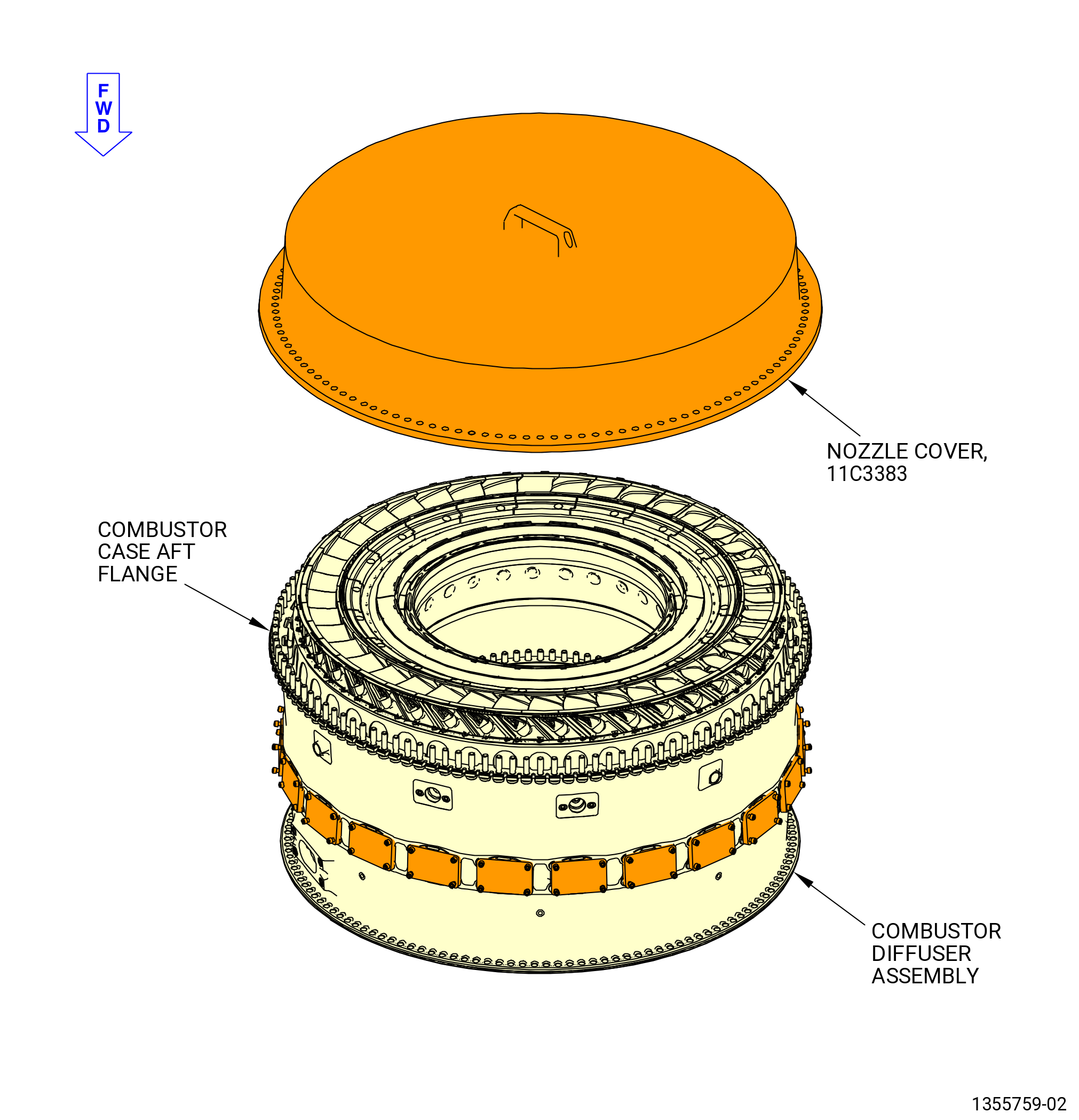
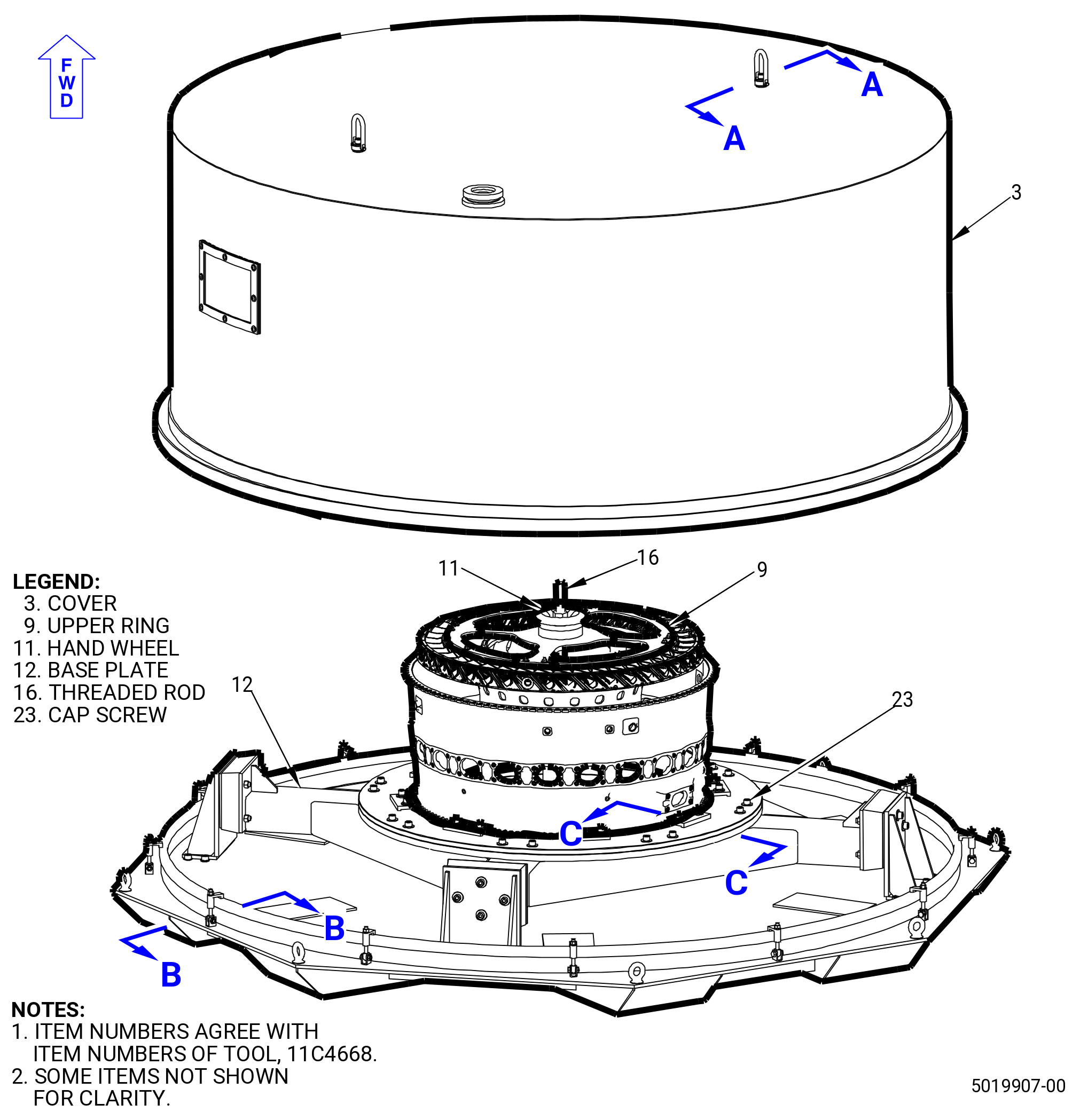
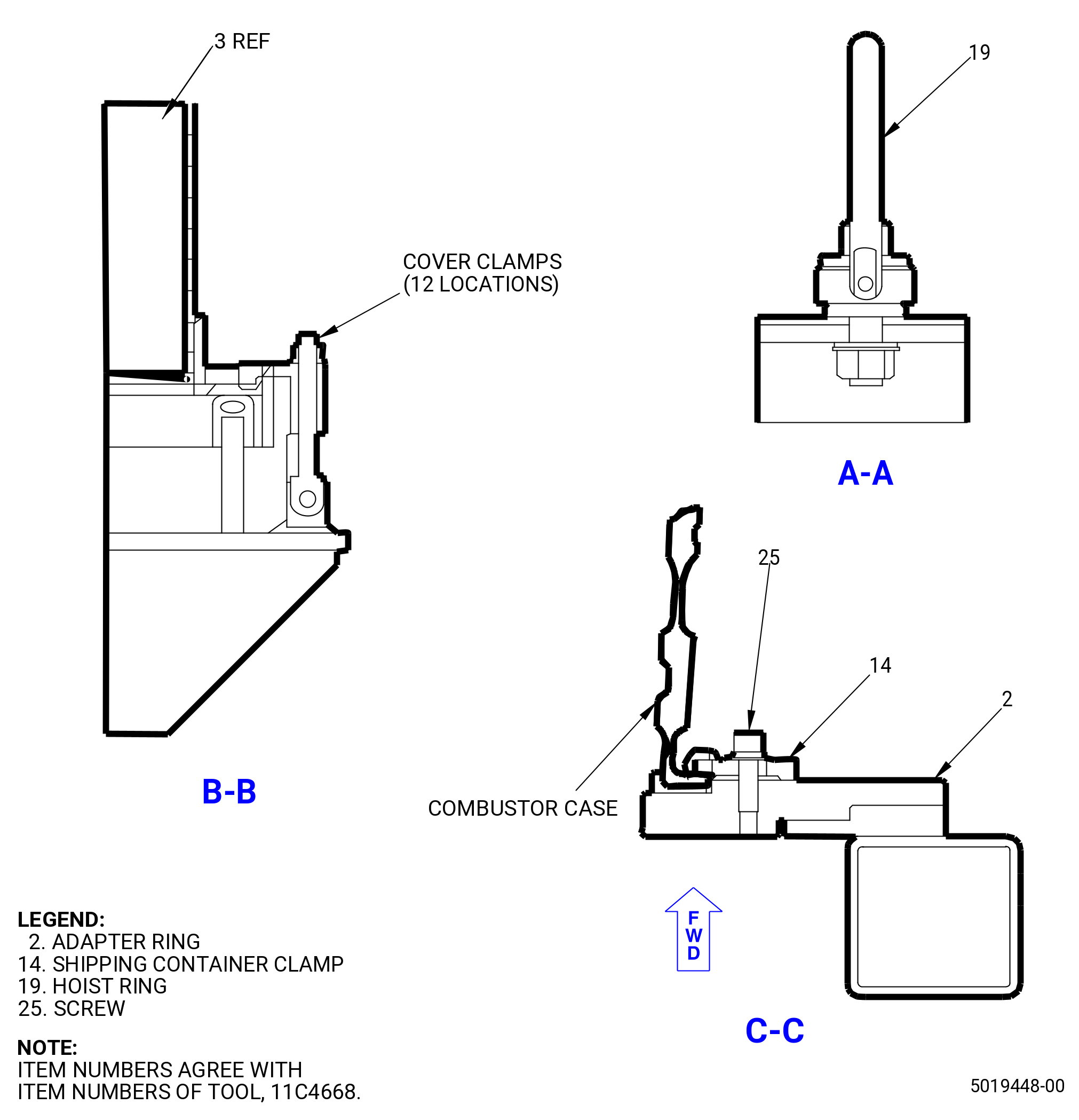
| I. | Install the 11C3383 nozzle cover. Put the 11C3383 nozzle cover on the aft end of the assembly with the lip over the aft flange of the combustor case (12001) aligning the “TOP VERT” mark on the cover with the top vertical center line of the combustor case. Refer to Figure 1013. |
| Subtask 72-40-00-440-077 |
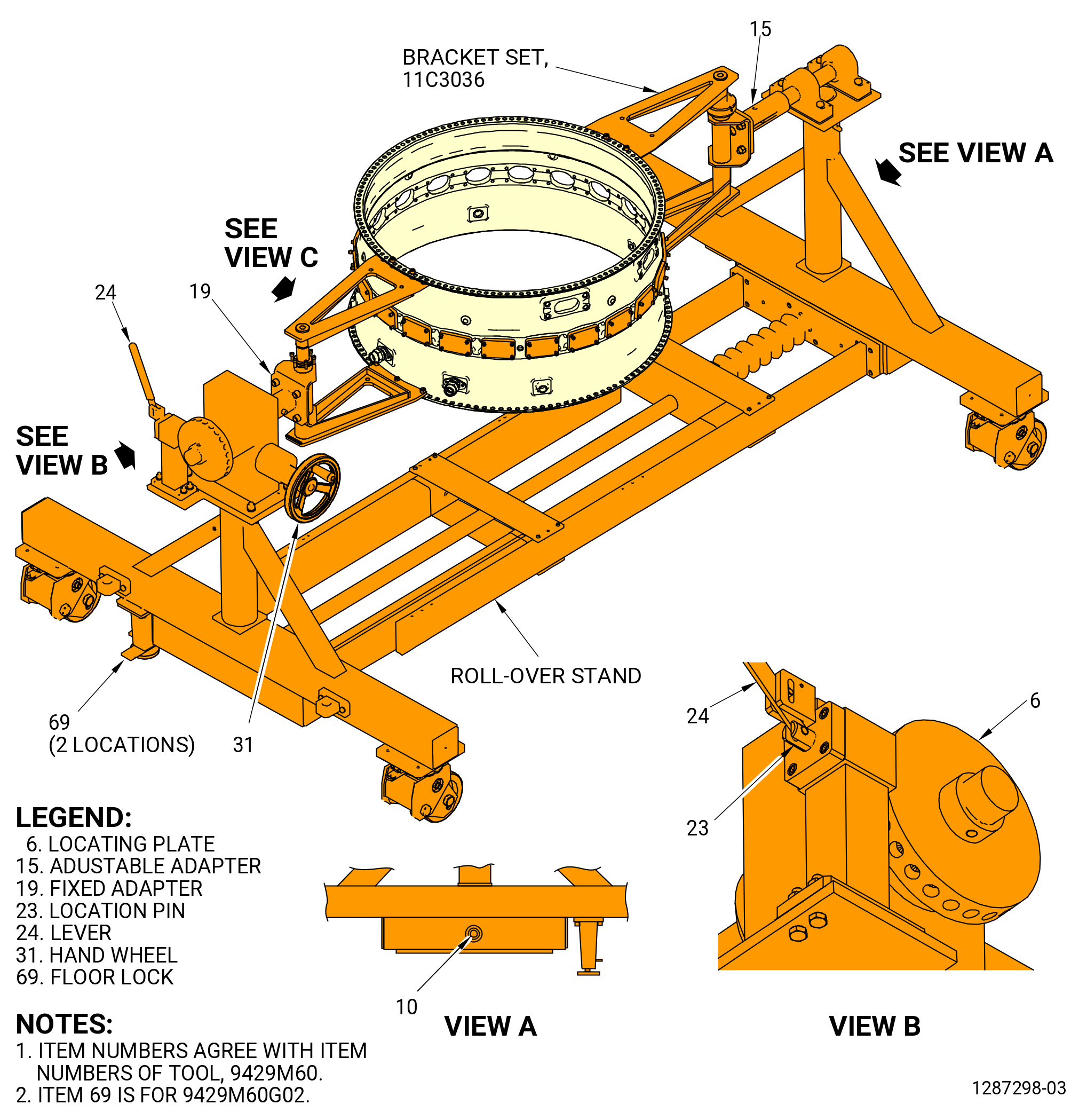
| J. | Turn the combustor case forward end up in the 9429M60 roll-over stand. Refer to Figure 1014 and do as follows: |
| (1) | Make sure that the combustor case is correctly installed in the 11C3036 bracket set on the 9429M60 roll-over stand. |
| CAUTION: |
|
| (a) | Lower the floor locks (item 69) of the 9429M60 roll-over stand until they touch the floor. The floor locks must touch the floor to prevent movement of the roll-over stand. Make sure that the roll-over stand is level. |
| (2) | Push the lever (item 24) to unlock the hand wheel (item 31). |
| (3) | Turn the hand wheel (item 31) to put the forward end of the combustor case up. |
| CAUTION: |
|
| (4) | Pull the lever (item 24) to engage the locating pin (item 23) into the locating plate (item 6) to lock the hand wheel (item 31). |
| Subtask 72-40-00-440-011 |
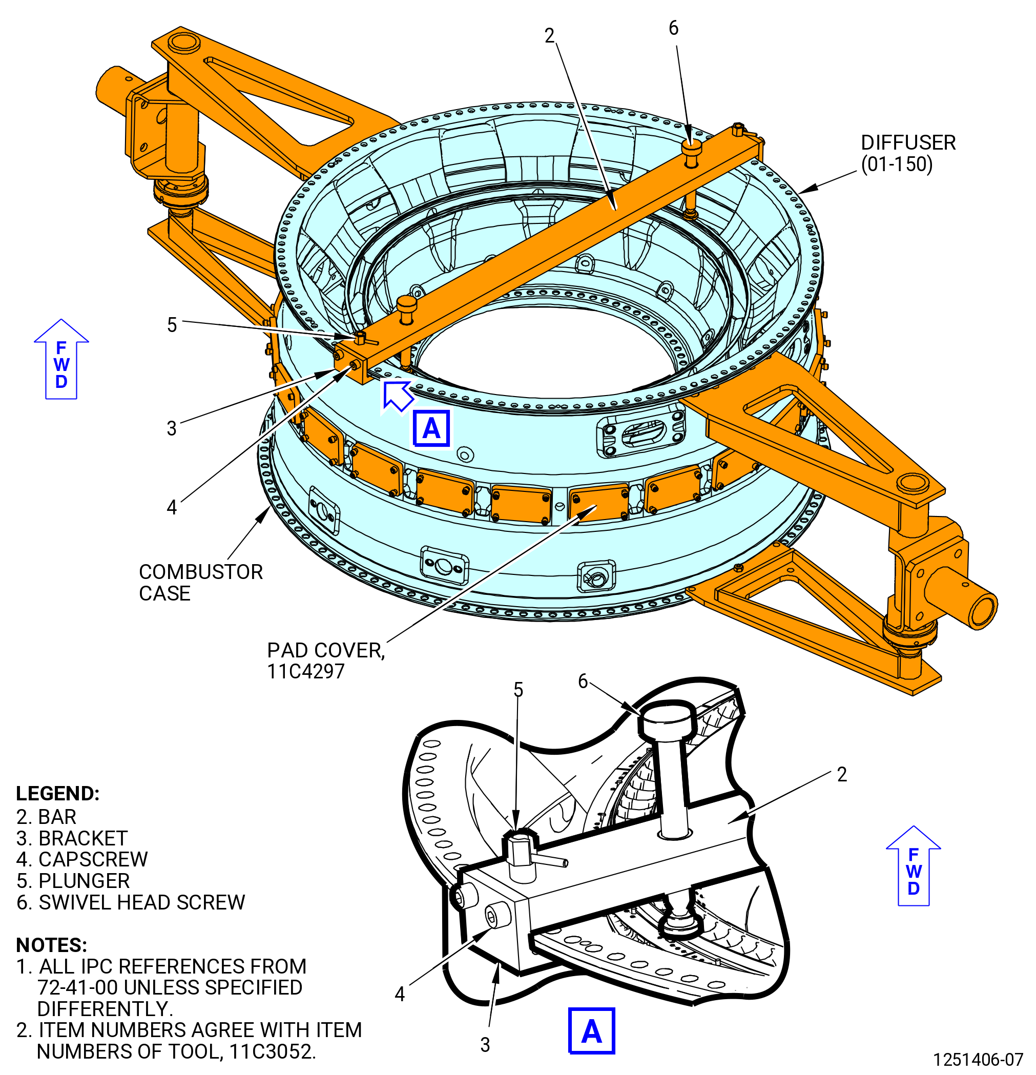
| K. | Remove the 11C3052 restraint fixture as follows. Refer Figure 1015. |
| (1) | Loosen each swivel head screw (item 6). |
| (2) | Remove the plungers (item 5) from the combustor case forward flange boltholes and move the bar (item 2) away from the center of the case to disengage side brackets (item 3) from the flange. |
| (3) | Remove the 11C3052 restraint fixture. |
| Subtask 72-40-00-440-078 |
| L. | Turn the CDN assembly (33-019 , 72-00-02) (SIN 0010A) or (33-020 , 72-00-02) (SIN 0010A) forward end down in the 9429M60 roll-over stand. Refer to Figure 1014 and do as follows: |
| CAUTION: |
|
| (1) | Lower the floor locks (item 69) of the 9429M60 roll-over stand until they touch the floor. The floor locks must touch the floor to prevent movement of the roll-over stand. Make sure that the roll-over stand is level. |
| (2) | Push the lever (item 24) to unlock the hand wheel (item 31). |
| (3) | Turn the hand wheel (item 31) to put the forward end of the combustor case up. |
| CAUTION: |
|
| (4) | Pull the lever (item 24) to engage the locating pin (item 23) into the locating plate (item 6) to lock the hand wheel (item 31). |
| Subtask 72-40-00-440-079 |
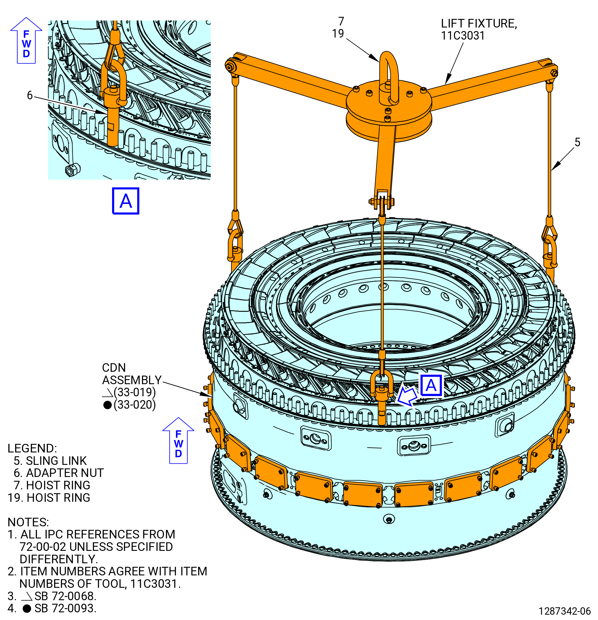
| M. | Remove the CDN assembly (33-019 , 72-00-02) (SIN 0010A) or (33-020 , 72-00-02) (SIN 0010A) from the 9429M60 roll-over stand. Refer to Figure 1016 and do as follows: |
| (1) | Install the 11C3031 lift fixture on the CDN aft flange as follows. |
| NOTE: |
|
| (a) | Attach the hoist ring (item 7) or (item 19) to an overhead hoist and position the 11C3031 lift fixture above the aft end of the CDN assembly. |
| (b) | Lower the adapter nuts (item 6) to the bolts in the aft flange of the CDN assembly. |
| (c) | Tighten the adapter nuts (item 6) by hand onto the bolts in the aft flange of the CDN assembly at three equally spaced locations until fully seated. |
| WARNING: |
|
| (d) | Lift the hoist to support the weight of the CDN assembly. |
| (2) | Remove the CDN assembly from the 9429M60 roll-over stand as follows. Refer to Figure 1014. |
| (a) | Remove the nuts (item 12) and capscrews (item 10) that attach the 11C3036 bracket set to the fixed adapter (item 19) and the adjustable adapter (item 15) of the 9429M60 roll-over stand. |
| (b) | Lift the hoist and remove the CDN assembly, with the 11C3036 bracket set installed, from the 9429M60 roll-over stand. |
| (3) | Put three inspection blocks of equal size on a clean, level, inspection table. Put the blocks in position at the 12:00 o'clock, 4:00 o'clock, and 8:00 o'clock positions. |
| (4) | Lower the CDN assembly onto the inspection blocks. Make sure that the blocks are slightly inboard of the boltholes on the forward flange. |
| (5) | Remove the 11C3031 lift fixture. |
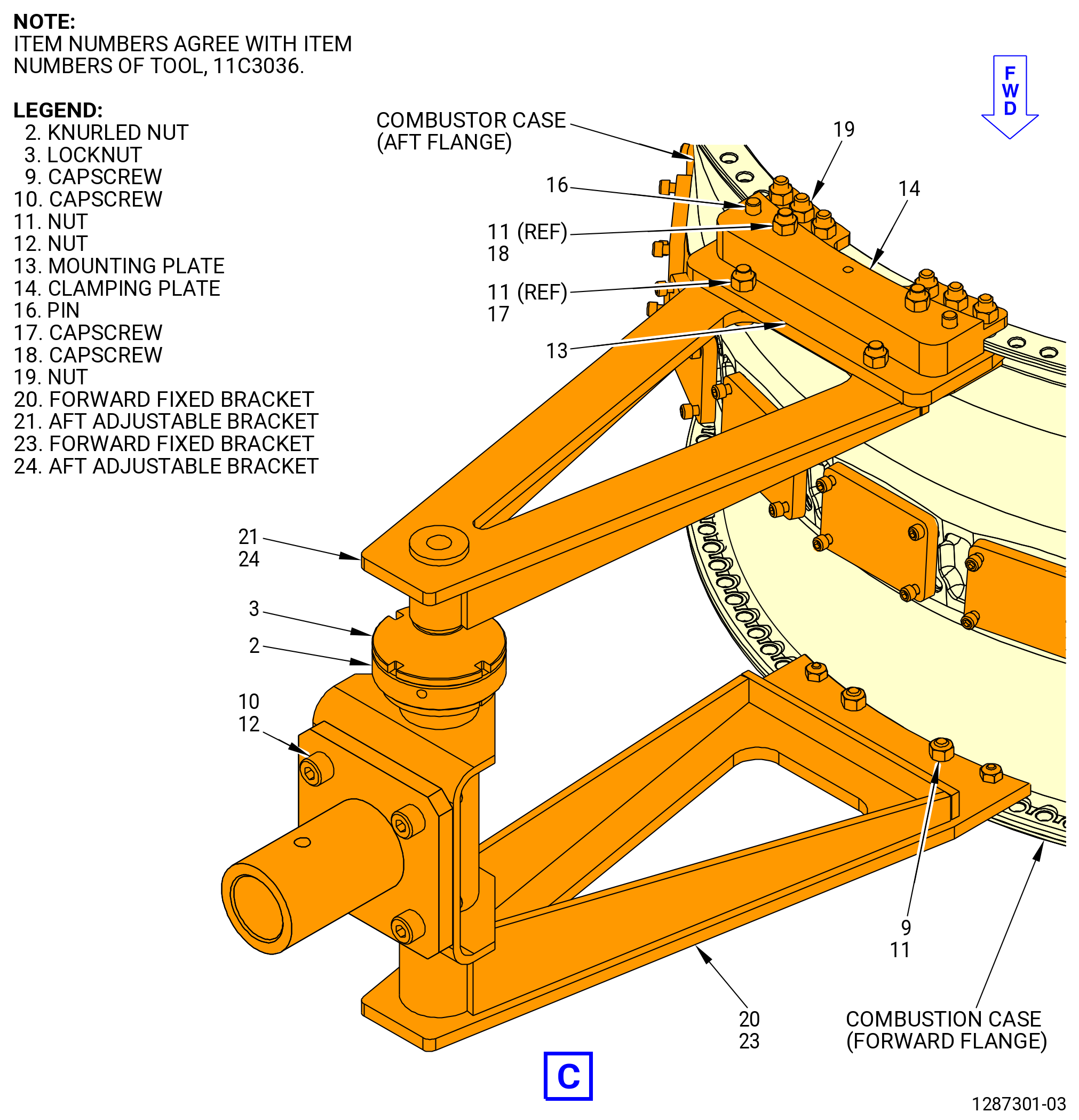
| (6) | Remove each bracket of the 11C3036 bracket set from the CDN assembly as follows: |
| NOTE: |
|
| (a) | Remove the nuts (item 11) and capscrews (item 9) that attach the forward fixed bracket (item 5) to the forward flange of the combustor case (12001). |
| (b) | Remove the nuts (item 11) and capscrews (item 18) that attach the aft adjustable brackets (item 21) or (item 24) to the aft flange of the combustor case. |
| (c) | Loosen the locknut (item 3) and turn the knurled nut (item 2) CCW to retract the aft adjustable brackets (item 21) or (item 24) from the combustor case flange. |
| (d) | Disengage the pins of the forward fixed brackets (item 20) or (item 23) from the forward flange of the combustor case. |
| (e) | Remove the bracket. |
| Subtask 72-40-00-220-009 |
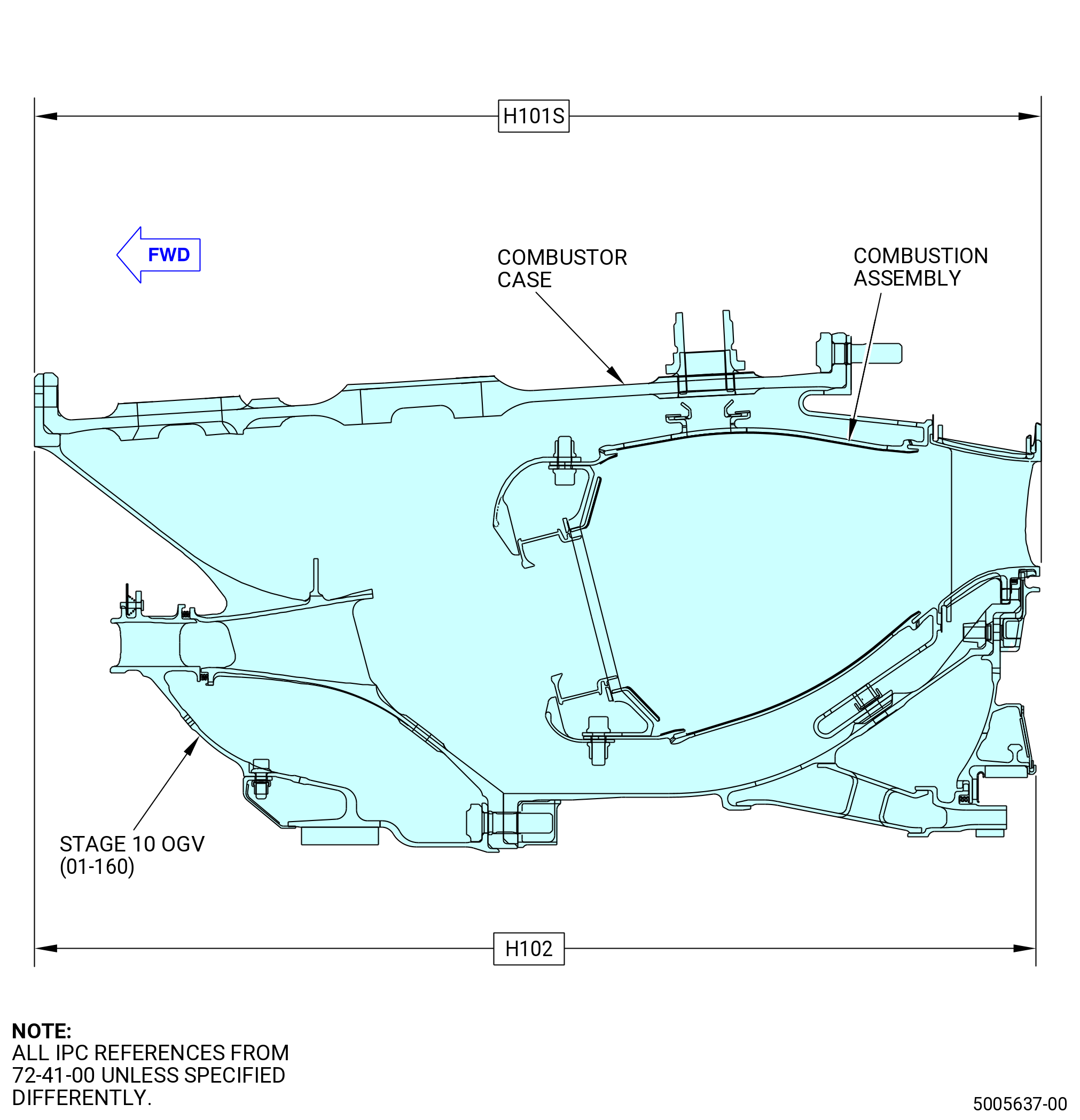
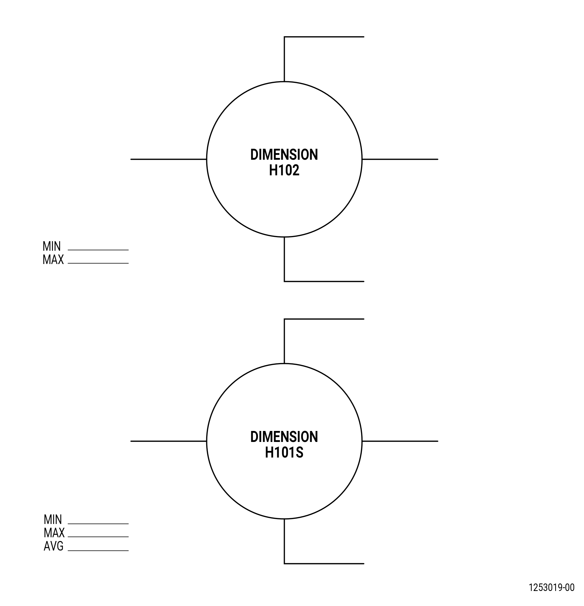
| N. | Measure H102 and H101S as follows: |
| (1) | Measure the dimension H102 at the 12:00 o'clock, 3:00 o'clock, 6:00 o'clock, and 9:00 positions. Refer to Figure 1017. |
| (2) | Record the maximum of the four H102 dimensions readings, 19.022-19.082 inches (483.16-484.68 mm). |
| (3) | Measure the dimension H101S at 12:00 o'clock, 3:00 o'clock, 6:00 o'clock, and 9:00 o'clock positions. |
| (a) | Record the average of the four readings. H101S limits are 19.079-19.113 inches (484.61-485.47 mm). |
| Subtask 72-40-00-440-017 |
| O. | Install the CDN assembly (33-019 , 72-00-02) (SIN 0010A) or (33-020 , 72-00-02) (SIN 0010A) on the 11C3010 build-up fixture. Refer to Figure 1019 and do as follows: |
| WARNING: |
|
| (1) | Clean the mating surface of the adapter ring (item 19) with C04-035 isopropyl alcohol, C04-002 Stoddard solvent, or a 50-50 blend of C04-035 isopropyl alcohol and C04-228 denatured alcohol. |
| (2) | Install the 11C3031 lift fixture on the CDN aft flange as follows. Refer to Figure 1016. |
| (a) | Attach the sling link (item 5) to an overhead hoist and position the lift fixture above the aft end of the CDN assembly. |
| (b) | Lower the adapter nuts (item 6) to the bolts in the aft flange of the CDN assembly. |
| (c) | Tighten the adapter nuts (item 6) by hand on the bolts in the aft flange of the CDN assembly at three equally spaced locations until they are firmly installed. |
| WARNING: |
|
| (3) | Lift the CDN assembly from the inspection table. |
| (4) | Install the CDN assembly on the 11C3010 build-up fixture as follows. Refer to Figure 1019. |
| (a) | Align the “TOP VERT” markings on the table adapter (item 24) and adapter ring (item 19) of the 11C3010 build-up fixture. |
| (b) | Align the forward flange of the HPT module with the adapter ring (item 19). Align the “TOP VERT” marking on the combustor case with the marking on the table adapter (item 24). |
| (c) | Lower the HPT module on the adapter ring (item 19). Make sure that the CDP bolts go through the boltholes in the table adapter (item 24). |
| (d) | Tighten the eight cap screws (item 13) to hold the HPT module on the 11C3010 build-up fixture. |
| (5) | Remove the 11C3031 lift fixture from the CDN aft flange. |
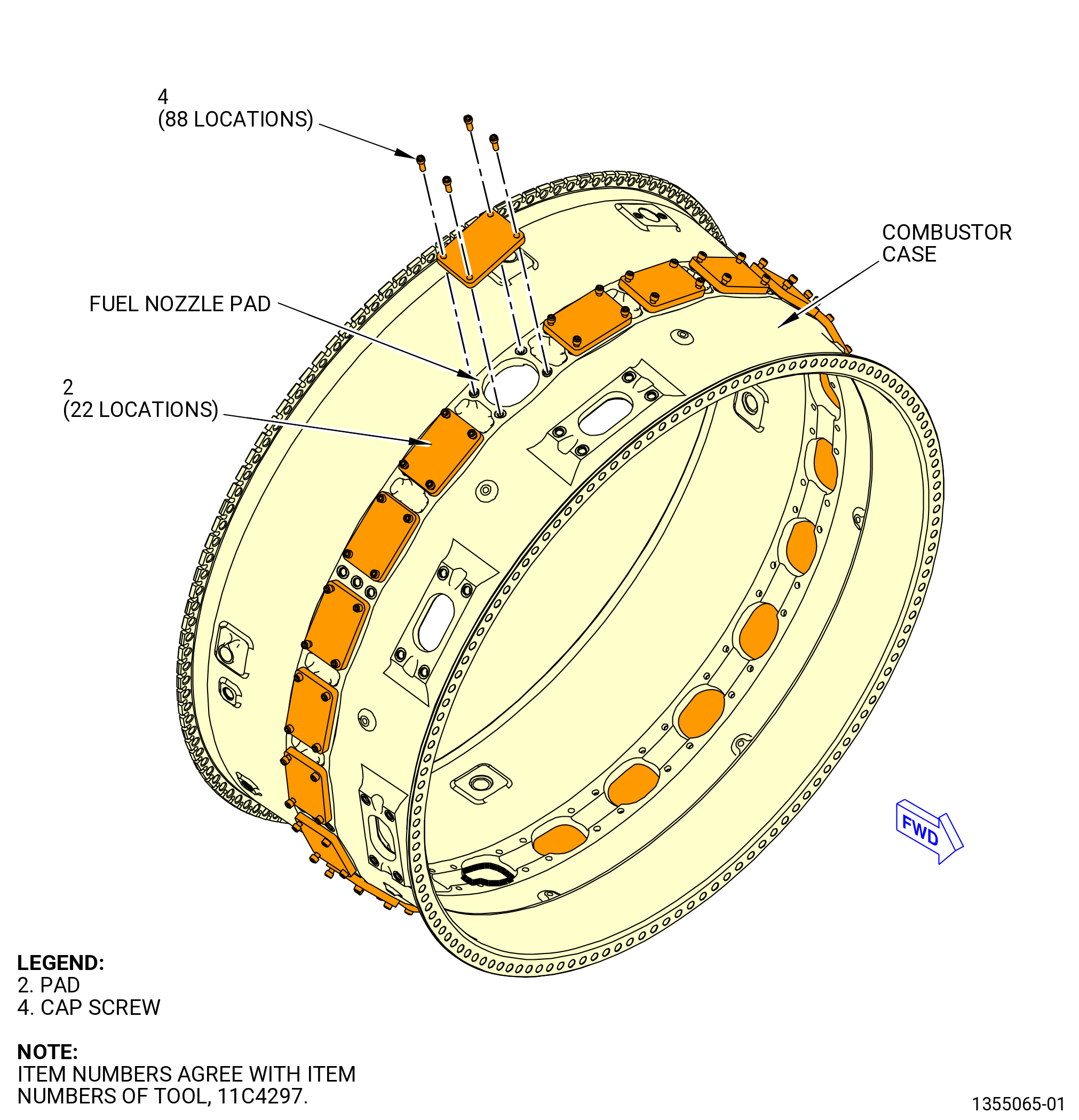
| P. | Remove the 11C4297 pad covers from the combustor case fuel nozzle pads. Refer to Figure 1018. |
| Subtask 72-40-00-440-085 |
| CAUTION: |
|
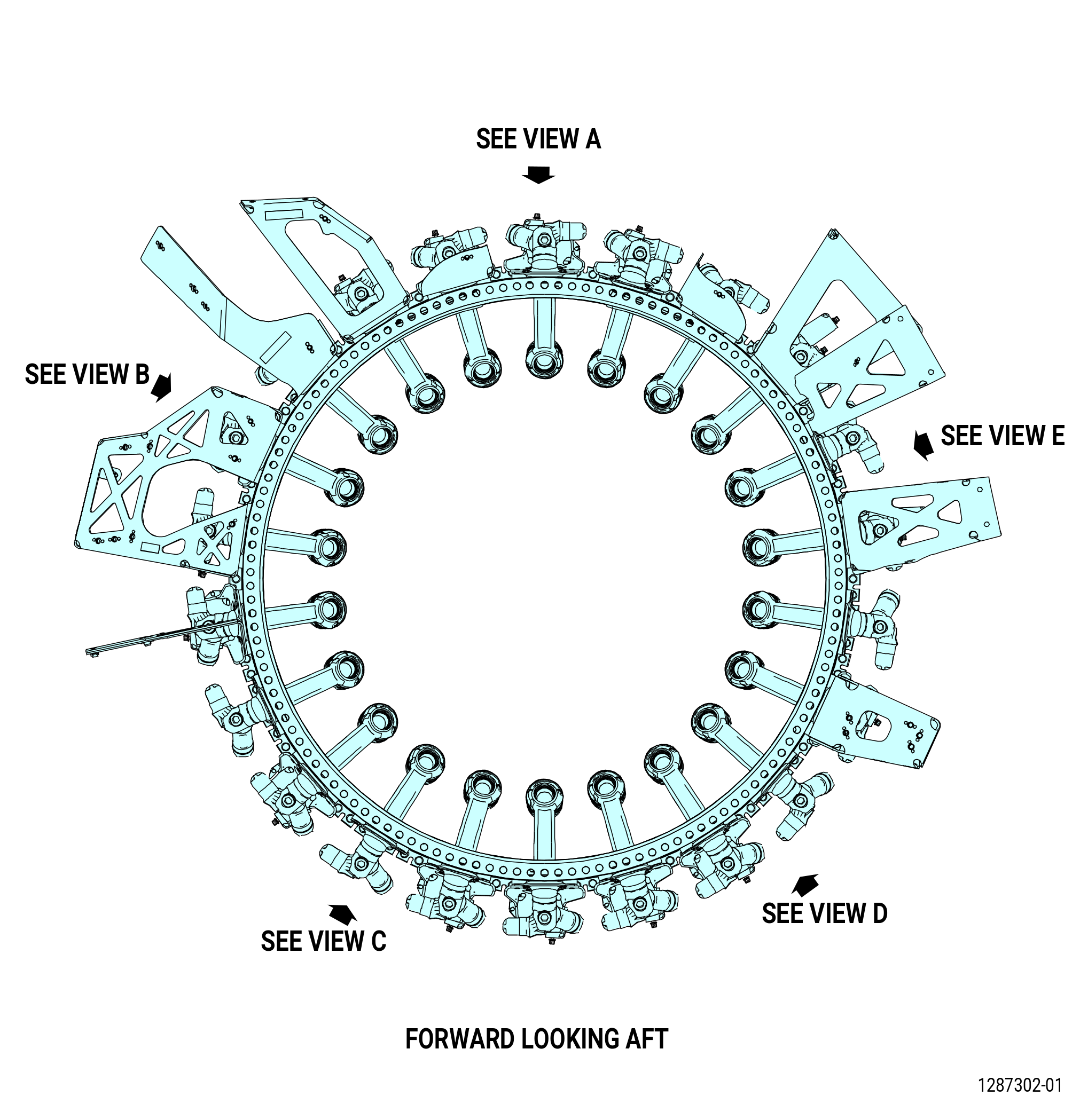
| Q. | Install the 22 fuel nozzles (12500), (12501), and seal assemblies (05-020 , 73-11-30) (SIN 12550) in the combustor case. Refer to Figure 1020 and do as follows: |
| CAUTION: |
|
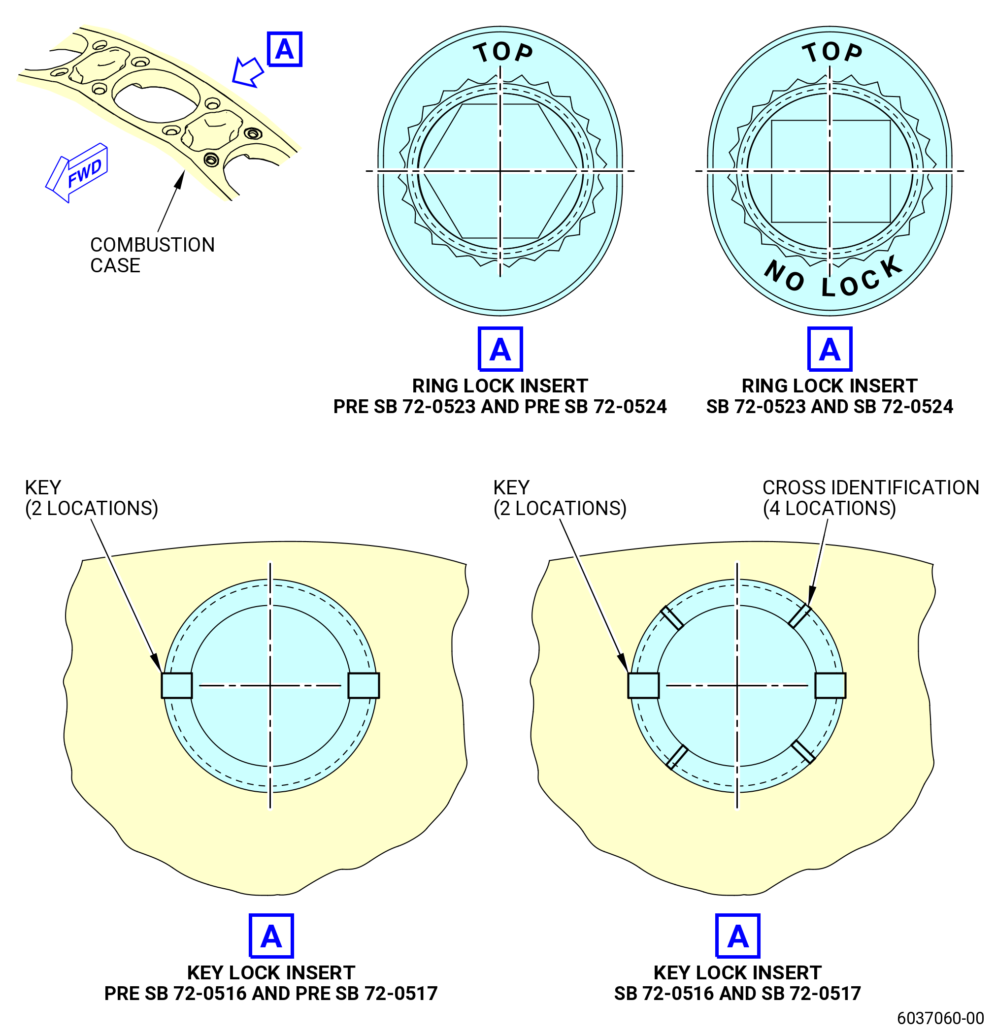
| (1) | Do a check of the CDN case compliance to SB 72-0516, SB 72-0517, SB 72-0523, SB 72-0524, and SB 72-0532. Refer to Figure 1021 and as follows: |
| (a) | SB 72-0516, SB 72-0517, SB 72-0523, and SB 72-0524 inserts have unique marking located at top surface. Refer to Figure 1021. |
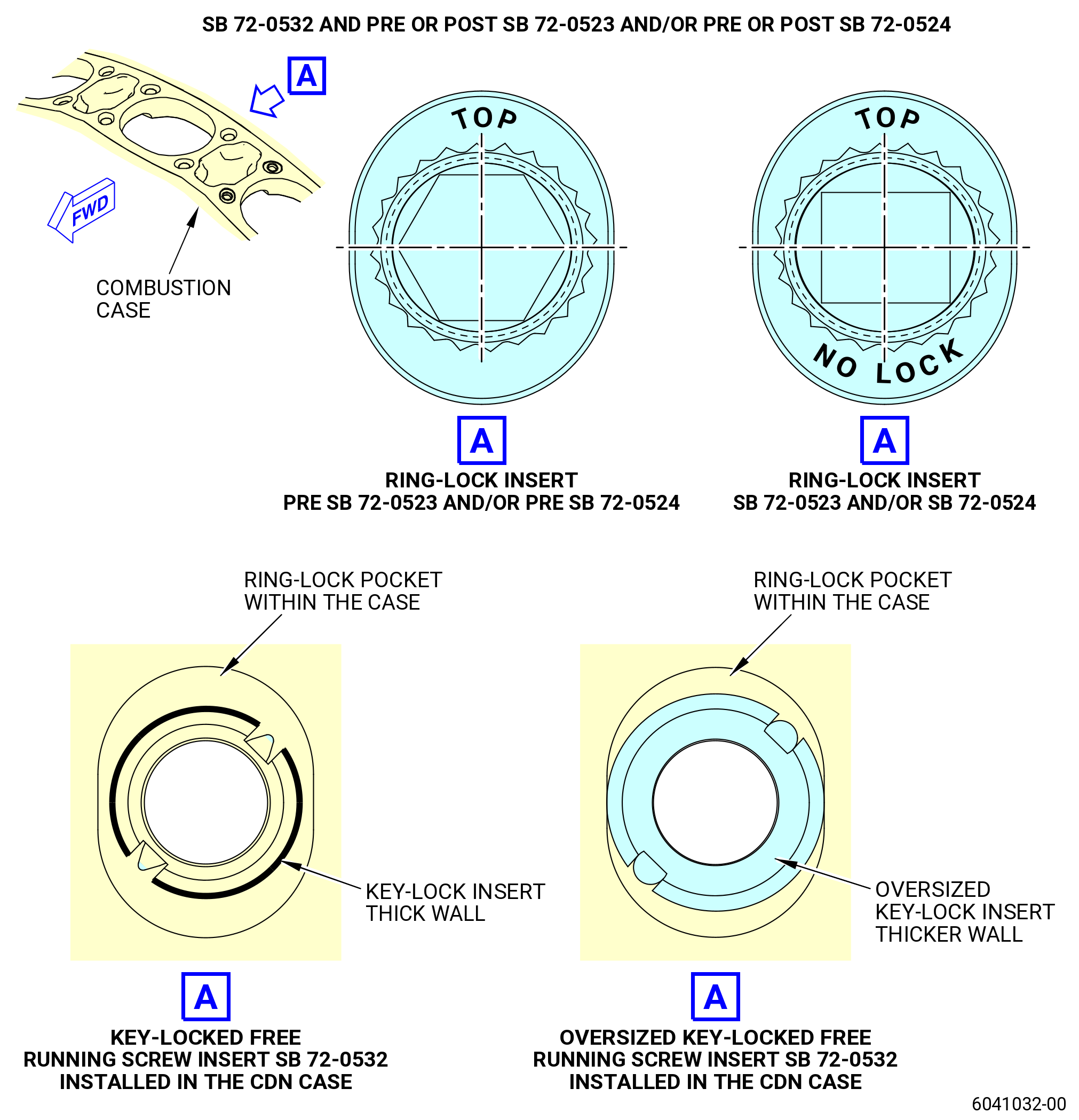
| (b) | SB 72-0532 key-locked free running screw insert and/or oversized key-locked free running screw insert can be installed in quantity as required to fuel nozzle pads. SB 72-0532 is applicable to all CDN case insert configurations. |
| (c) | In effect, SB 72-0532 and PRE SB 72-0366 and/or SB 72-0523 and/or SB 72-0524 configuration results in intermixed insert configuration with key-locked free running screw insert (SB 72-0532) and/or oversized key-locked free running screw insert (SB 72-0532) in quantity as required and all remaining ring-lock inserts (PRE SB 72-0366) and/or free running ring-locked inserts (SB 72-0523 and/or SB 72-0524) installed. The new SB 72-0532 screw inserts have thicker wall comparing to PRE SB 72-0366 , SB 72-0523 and SB 72-0524 inserts. Refer to Figure 1021. |
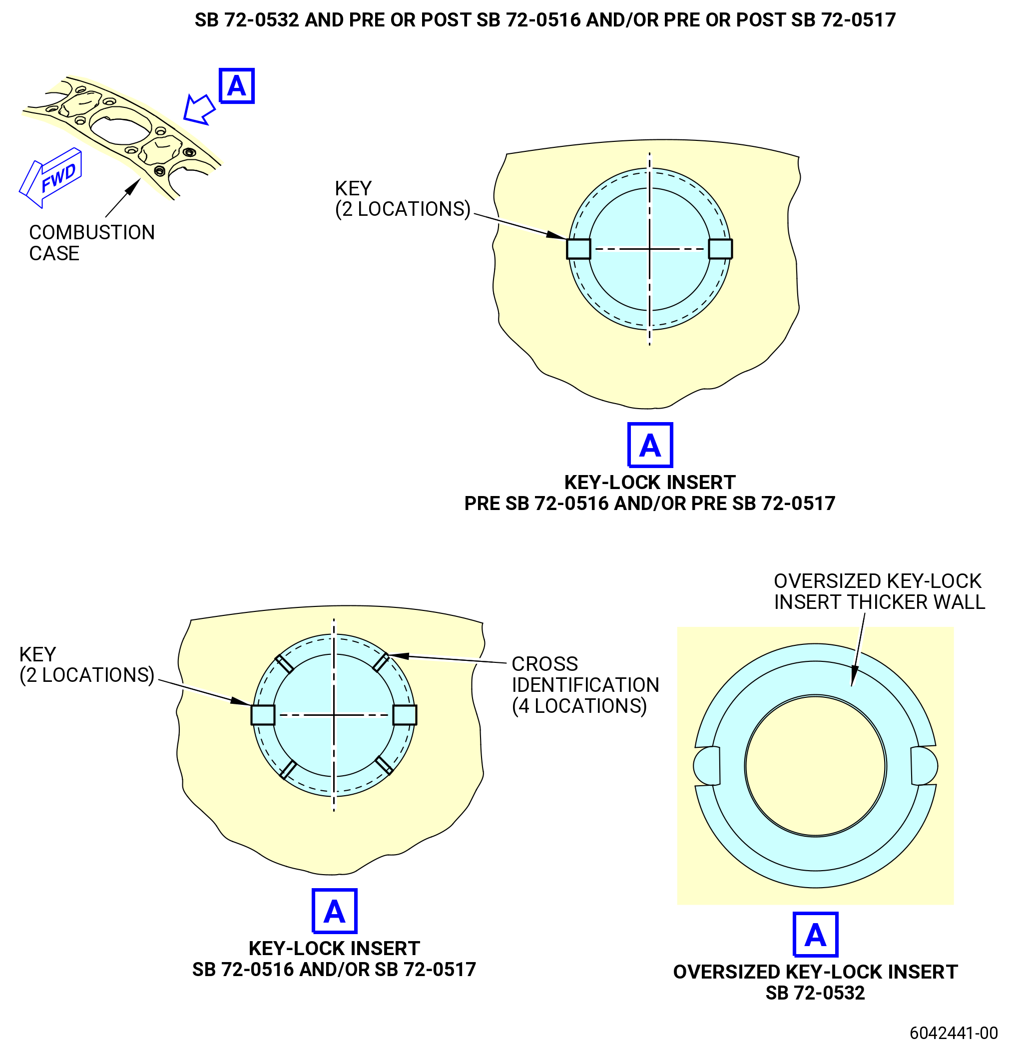
| (d) | SB 72-0532 and SB 72-0366 and/or POST SB 72-0516 and/or SB 72-0517 configuration results in intermixed insert configuration with oversized key-locked free running screw insert (SB 72-0532) in quantity as required and all remaining key-locked screw inserts (SB 72-0366) and/or key-locked free running screw inserts (SB 72-0516 and/or SB 72-0517). The new oversized key-locked free running screw insert has thicker wall comparing to SB 72-0366, 72-0516 and 72-0517 inserts. Refer to Figure 1021. |
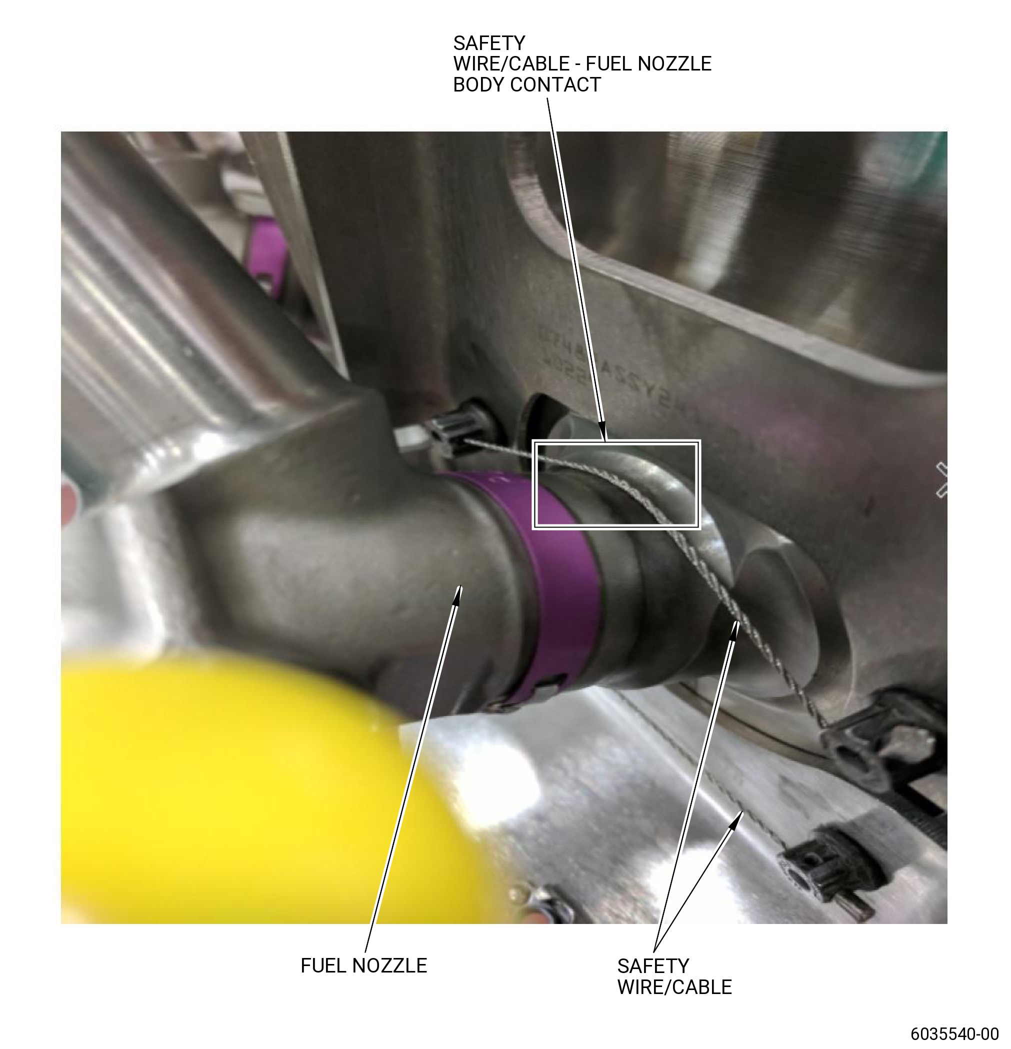
| (e) | Make sure that the SB 72-0516 or SB 72-0517 or SB 72-0523 or SB 72-0524 or SB 72-0532 inserts are being assembled with bolts (05-010 , 73-11-30) (SIN 12520) and safety cable/wire. |
| WARNING: |
|
| CAUTION: |
|
| (2) | Apply C02-097 lubricant or optionally C02-058 lubricant to the threads and friction surfaces of the 88 bolts (05-010 , 73-11-30) (SIN 12520). |
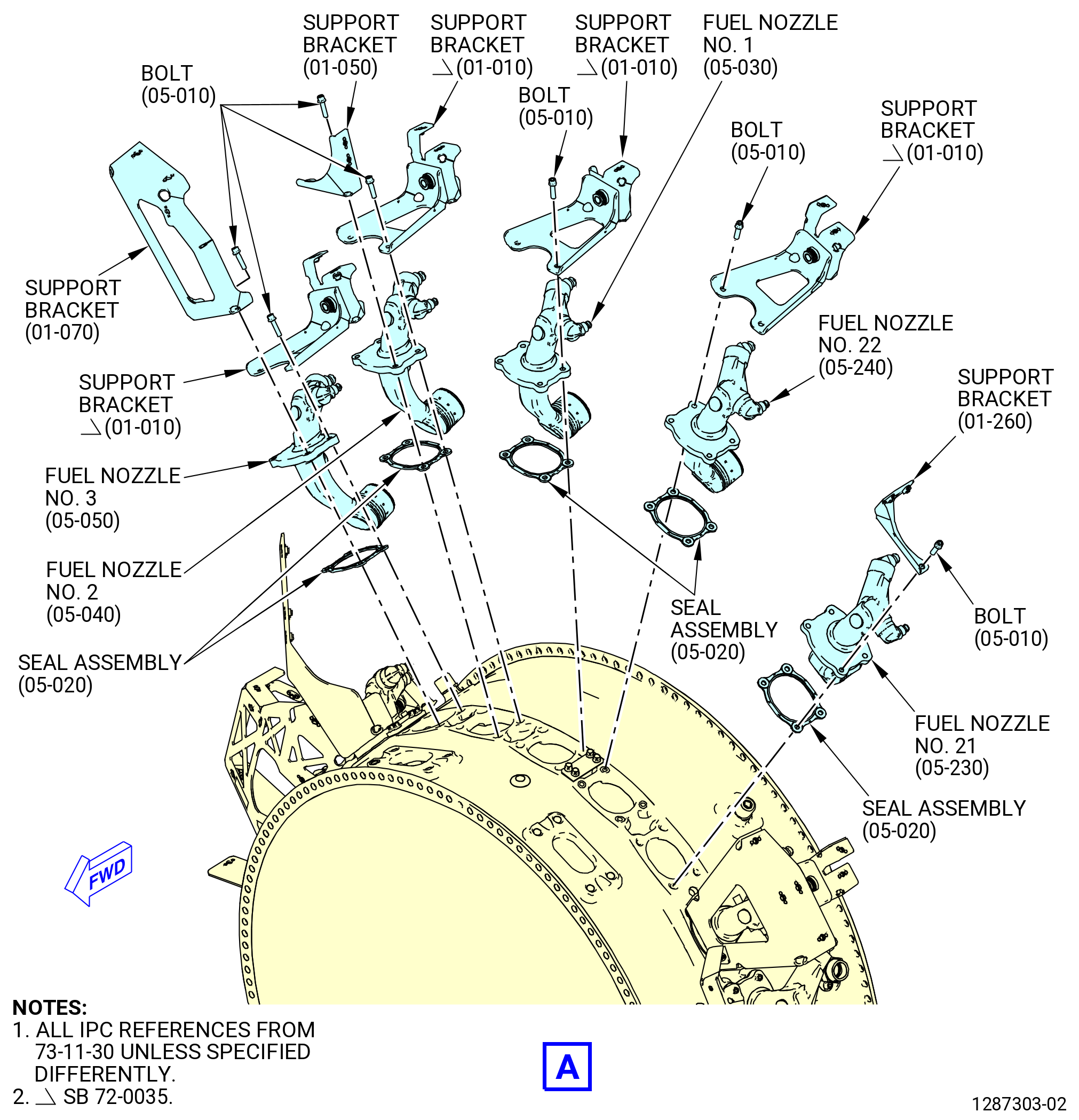
| (3) | Install the No. 1 fuel nozzle (05-030 , 73-11-30) (SIN 12500) in the combustor case as follows: |
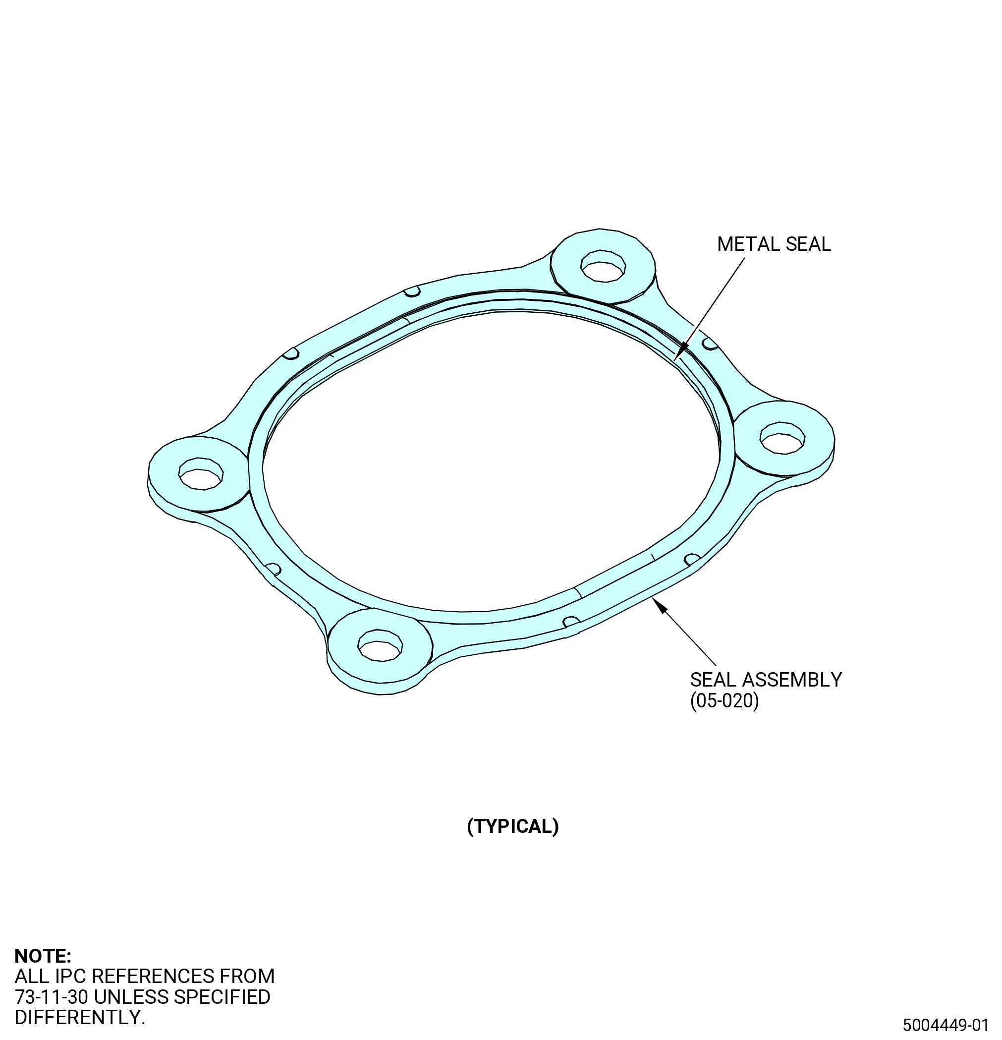
| (a) | Make sure that the inner metal seal is in position on the seal assembly (05-020 , 73-11-30) (SIN 12550). |
| (b) | Install the fuel nozzle and seal assembly on the combustor case. |
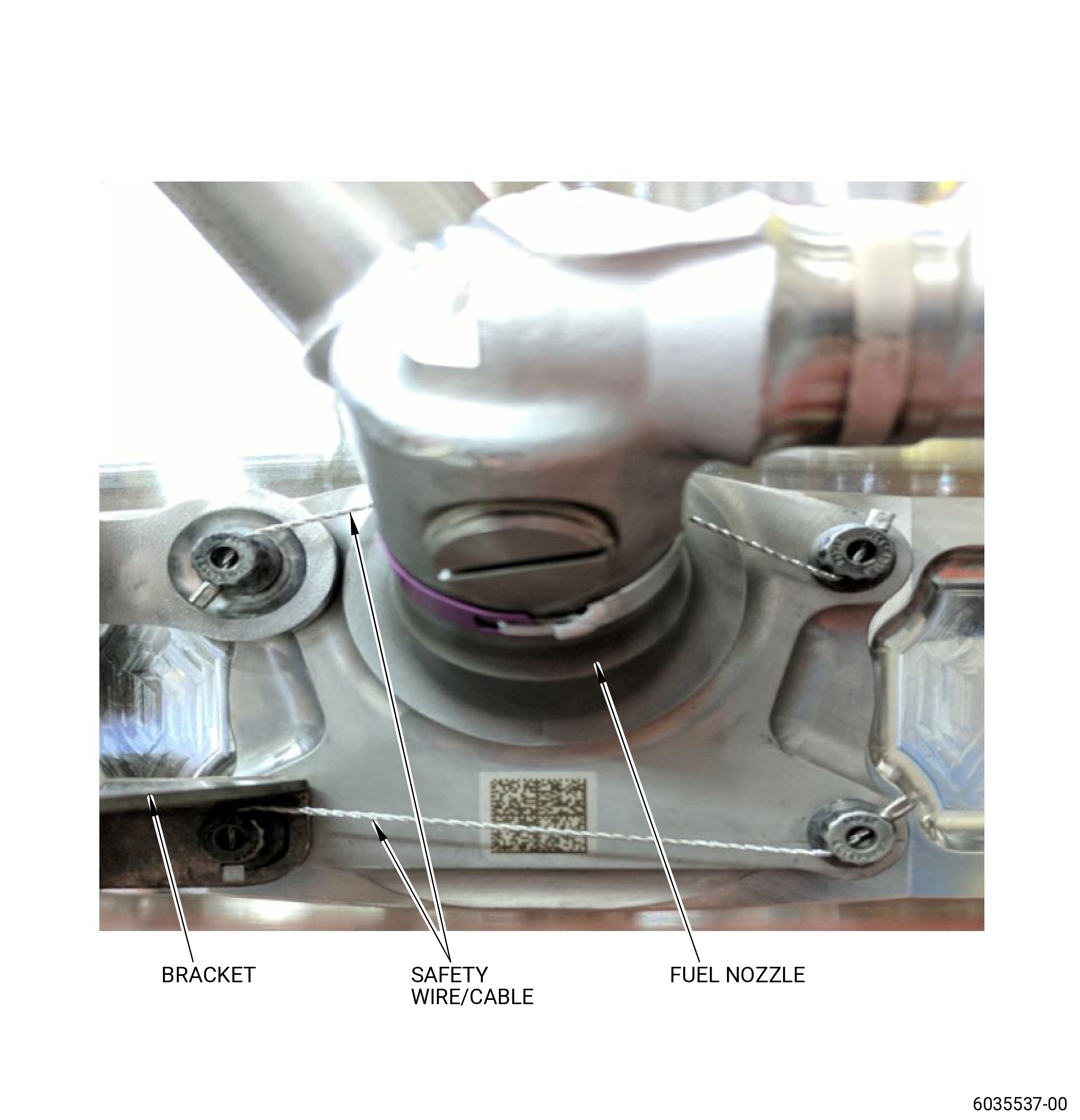
| (c) | Install the support bracket (01-010 , 73-11-30) (SIN 3411A) in the aft boltholes on top of the fuel nozzle. |
| (d) | Attach the fuel nozzle, the seal assembly, and the support bracket to the combustor case with four bolts (05-010 , 73-11-30) (SIN 12520). Hand-tighten the bolts. Do not torque the bolts at this time. |
| CAUTION: |
|
| (e) | Do a visual inspection for the correct position of the fuel nozzle seal assembly as follows: |
| 1 | Make sure the four bolts (05-010 , 73-11-30) (SIN 12520) go through each seal assembly (05-020 , 73-11-30) (SIN 12550) bolthole. |
| (f) | Make sure that the fuel nozzle is inside the combustion chamber liner and radial mixer. |
| (4) | Install the No. 2 fuel nozzle (05-040 , 73-11-30) (SIN 12500) in the combustor case as follows: |
| (a) | Make sure that the inner metal seal is in position on the seal assembly (05-020 , 73-11-30) (SIN 12550). |
| (b) | Install the fuel nozzle and seal assembly on the combustor case. |
| (c) | Install the support bracket (01-010 , 73-11-30) (SIN 3411A) in the aft holes and the fuel tube support bracket (support bracket) (01-050 , 73-11-30) (SIN 34113) in the fwd boltholes on top of the fuel nozzle. |
| (d) | Attach the fuel nozzle, the seal assembly, and the support brackets to the combustor case with the bolts (05-010 , 73-11-30) (SIN 12520). Hand-tighten the bolts. Do not torque the bolts at this time. |
| CAUTION: |
|
| (e) | Do a visual inspection for the correct position of the fuel nozzle seal assembly as follows: |
| 1 | Make sure the four bolts (05-010 , 73-11-30) (SIN 12520) go through each seal assembly (05-020 , 73-11-30) (SIN 12550) bolthole. |
| (f) | Make sure that the fuel nozzle is inside the combustion chamber liner and radial mixer. |
| (5) | Install the No. 3 fuel nozzle (05-050 , 73-11-30) (SIN 12500) in the combustor case as follows: |
| (a) | Make sure that the inner metal seal is in position on the seal assembly (05-020 , 73-11-30) (SIN 12550). |
| (b) | Install the fuel nozzle and the seal assembly on the combustor case. |
| (c) | Install the support bracket (01-010 , 73-11-30) (SIN 3411A) in the aft holes and the stage 7 air support bracket (support bracket) (01-070 , 73-11-30) (SIN 61110) in the fwd boltholes on top of the fuel nozzle. |
| (d) | Attach the fuel nozzle, the seal assembly, and the support brackets to the combustor case with the bolts (05-010 , 73-11-30) (SIN 12520). Hand-tighten the bolts. Do not torque the bolts at this time. |
| CAUTION: |
|
| (e) | Do a visual inspection for the correct position of the fuel nozzle seal assembly as follows: |
| 1 | Make sure the four bolts (05-010 , 73-11-30) (SIN 12520) go through each seal assembly (05-020 , 73-11-30) (SIN 12550) bolthole. |
| (f) | Make sure that the fuel nozzle is inside the combustion chamber liner and radial mixer. |
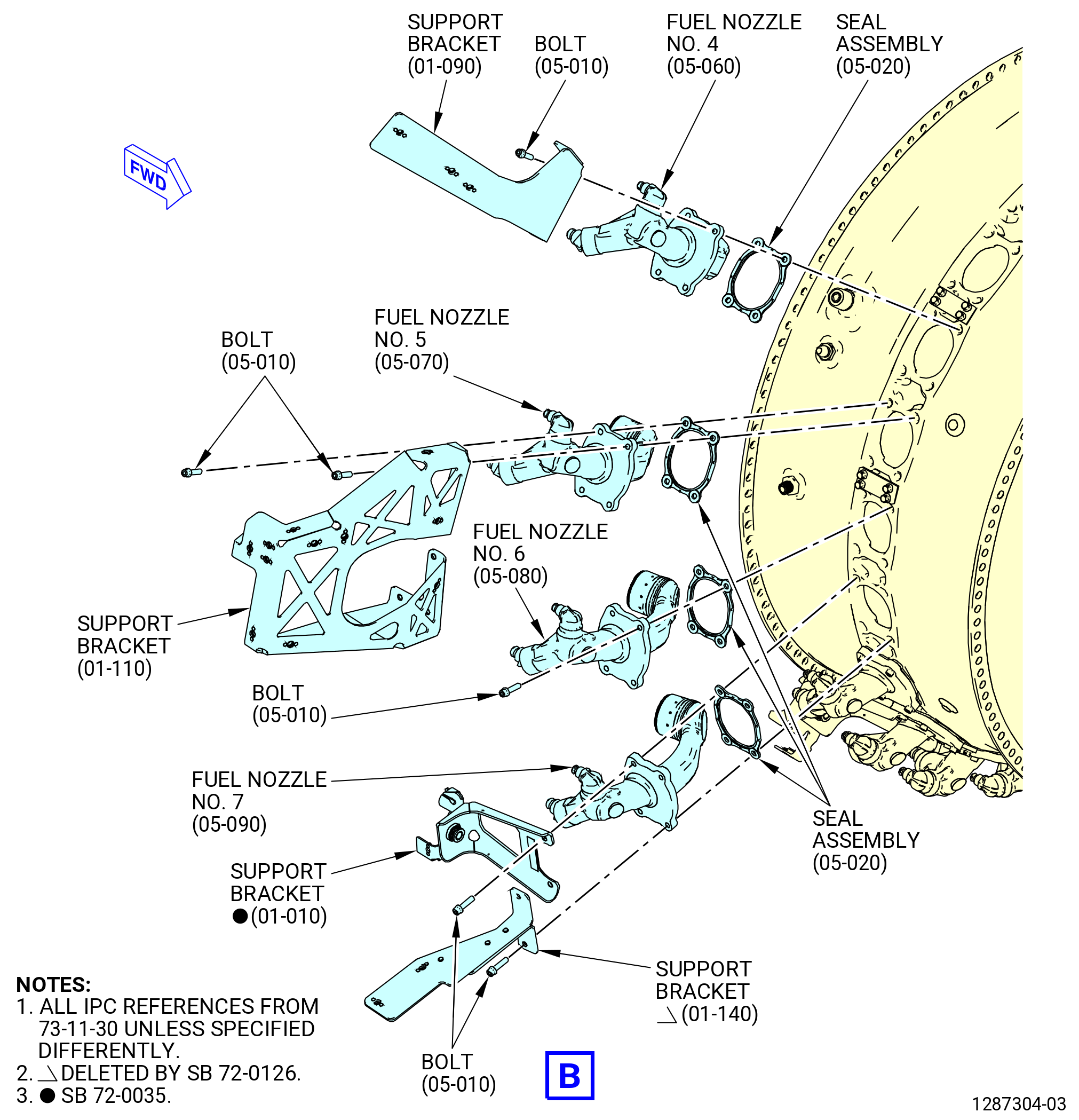
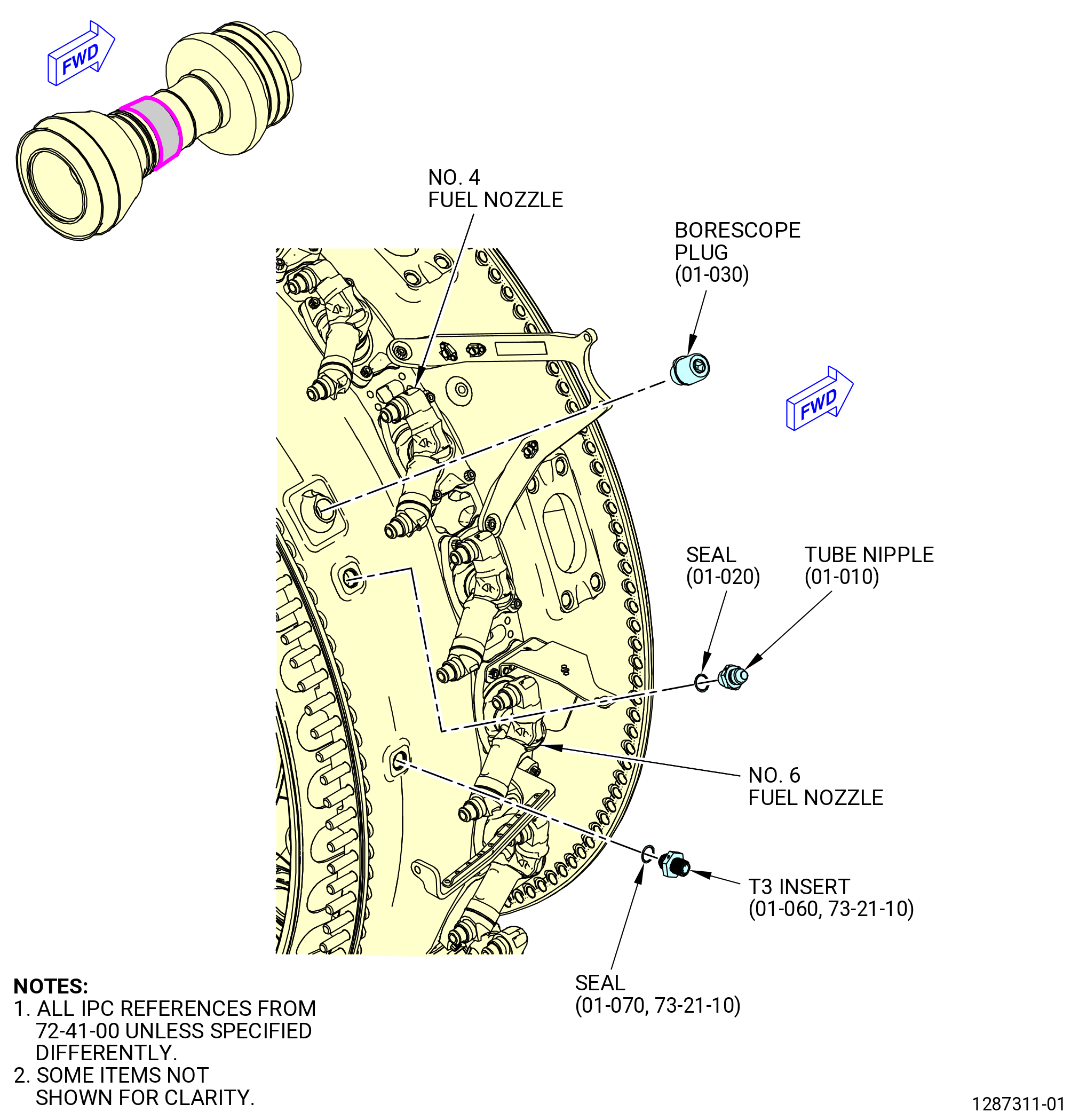
| (6) | Install the No. 4 fuel nozzle (05-060 , 73-11-30) (SIN 12500) in the combustor case as follows: |
| (a) | Make sure that the inner metal seal is in position on the seal assembly (05-020 , 73-11-30) (SIN 12550). |
| (b) | Install the fuel nozzle and the seal assembly on the combustor case. |
| (c) | Install the support bracket (01-090 , 73-11-30) (SIN 6121M) in the fwd boltholes on top of the fuel nozzle. |
| (d) | Attach the fuel nozzle, the seal assembly, and the support bracket to the combustor case with the bolts (05-010 , 73-11-30) (SIN 12520). Hand-tighten the bolts. Do not torque the bolts at this time. |
| CAUTION: |
|
| (e) | Do a visual inspection for the correct position of the fuel nozzle seal assembly as follows: |
| 1 | Make sure the four bolts (05-010 , 73-11-30) (SIN 12520) go through each seal assembly (05-020 , 73-11-30) (SIN 12550) bolthole. |
| (f) | Make sure that the fuel nozzle is inside the combustion chamber liner and radial mixer. |
| (7) | Install the No. 5 fuel nozzle (05-070 , 73-11-30) (SIN 12500) in the combustor case as follows: |
| (a) | Make sure that the inner metal seal is in position on the seal assembly (05-020 , 73-11-30) (SIN 12550). |
| (b) | Install the fuel nozzle and the seal assembly on the combustor case. |
| (c) | Install the support bracket (01-110 , 73-11-30) (SIN 61A12) in the fwd boltholes on top of the fuel nozzle. |
| NOTE: |
|
| (d) | Attach the fuel nozzle, the seal assembly, and the support bracket to the combustor case with the bolts (05-010 , 73-11-30) (SIN 12520). Hand-tighten the bolts. Do not torque the bolts at this time. |
| CAUTION: |
|
| (e) | Do a visual inspection for the correct position of the fuel nozzle seal assembly as follows: |
| 1 | Make sure the four bolts (05-010 , 73-11-30) (SIN 12520) go through each seal assembly (05-020 , 73-11-30) (SIN 12550) bolthole. |
| (f) | Make sure that the fuel nozzle is inside the combustion chamber liner and radial mixer. |
| (8) | Install the No. 6 fuel nozzle (05-080 , 73-11-30) (SIN 12500) in the combustor case as follows: |
| (a) | Make sure that the inner metal seal is in position on the seal assembly (05-020 , 73-11-30) (SIN 12550). |
| (b) | Install the fuel nozzle and the seal assembly on the combustor case. |
| (c) | Install the support bracket (01-110 , 73-11-30) (SIN 61A12) in the fwd boltholes on top of the fuel nozzle. |
| NOTE: |
|
| (d) | Attach the fuel nozzle, the seal assembly, and the support bracket to the combustor case with the bolts (05-010 , 73-11-30) (SIN 12520). Hand-tighten the bolts. Do not torque the bolts at this time. |
| CAUTION: |
|
| (e) | Do a visual inspection for the correct position of the fuel nozzle seal assembly as follows: |
| 1 | Make sure the four bolts (05-010 , 73-11-30) (SIN 12520) go through each seal assembly (05-020 , 73-11-30) (SIN 12550) bolthole. |
| (f) | Make sure that the fuel nozzle is inside the combustion chamber liner and radial mixer. |
| (9) | Install the No. 7 fuel nozzle (05-090 , 73-11-30) (SIN 12500) in the combustor case as follows: |
| (a) | Make sure that the inner metal seal is in position on the seal assembly (05-020 , 73-11-30) (SIN 12550). |
| (b) | Install the fuel nozzle and the seal assembly on the combustor case. |
| (c) | Install the support bracket (01-010 , 73-11-30) (SIN 3411A) in the aft boltholes on top of the fuel nozzle. |
| Subtask 72-40-00-440-160 |
| * * * PRE SB 72-0126( Installation of the No. 7 Fuel Nozzle with the 7th Stage Air Support Bracket ) |
| (d) | Install the 7th air support bracket (support bracket) (01-140 , 73-11-30) (SIN 61114) in the fwd boltholes on top of the fuel nozzle. |
| NOTE: |
|
| * * * END PRE SB 72-0126 |
| Subtask 72-40-00-440-161 |
| * * * PRE SB 72-0126( Installation of the No. 7 Fuel Nozzle with the 7th Stage Air Support Bracket ) |
| (e) | Attach the fuel nozzle, the seal assembly, and the support brackets (01-010 , 73-11-30) (SIN 3411A) and (01-140 , 73-11-30) (SIN 61114) to the combustor case with the bolts (05-010 , 73-11-30) (SIN 12520). Hand-tighten the bolts. Do not torque the bolts at this time. |
| * * * END PRE SB 72-0126 |
| Subtask 72-40-00-440-162 |
| * * * SB 72-0126( Installation of the No. 7 Fuel Nozzle without the 7th Stage Air Support Bracket ) |
| (e).A. | Attach the fuel nozzle, the seal assembly, and the support bracket (01-010 , 73-11-30) (SIN 3411A) to the combustor case with the bolts (05-010 , 73-11-30) (SIN 12520). Hand-tighten the bolts. Do not torque the bolts at this time. |
| * * * END SB 72-0126 |
| Subtask 72-40-00-440-163 |
| CAUTION: |
|
| (f) | Do a visual inspection for the correct position of the fuel nozzle seal assembly as follows: |
| 1 | Make sure the four bolts (05-010 , 73-11-30) (SIN 12520) go through each seal assembly (05-020 , 73-11-30) (SIN 12550) bolthole. |
| (g) | Make sure that the fuel nozzle is inside the combustion chamber liner and radial mixer. |
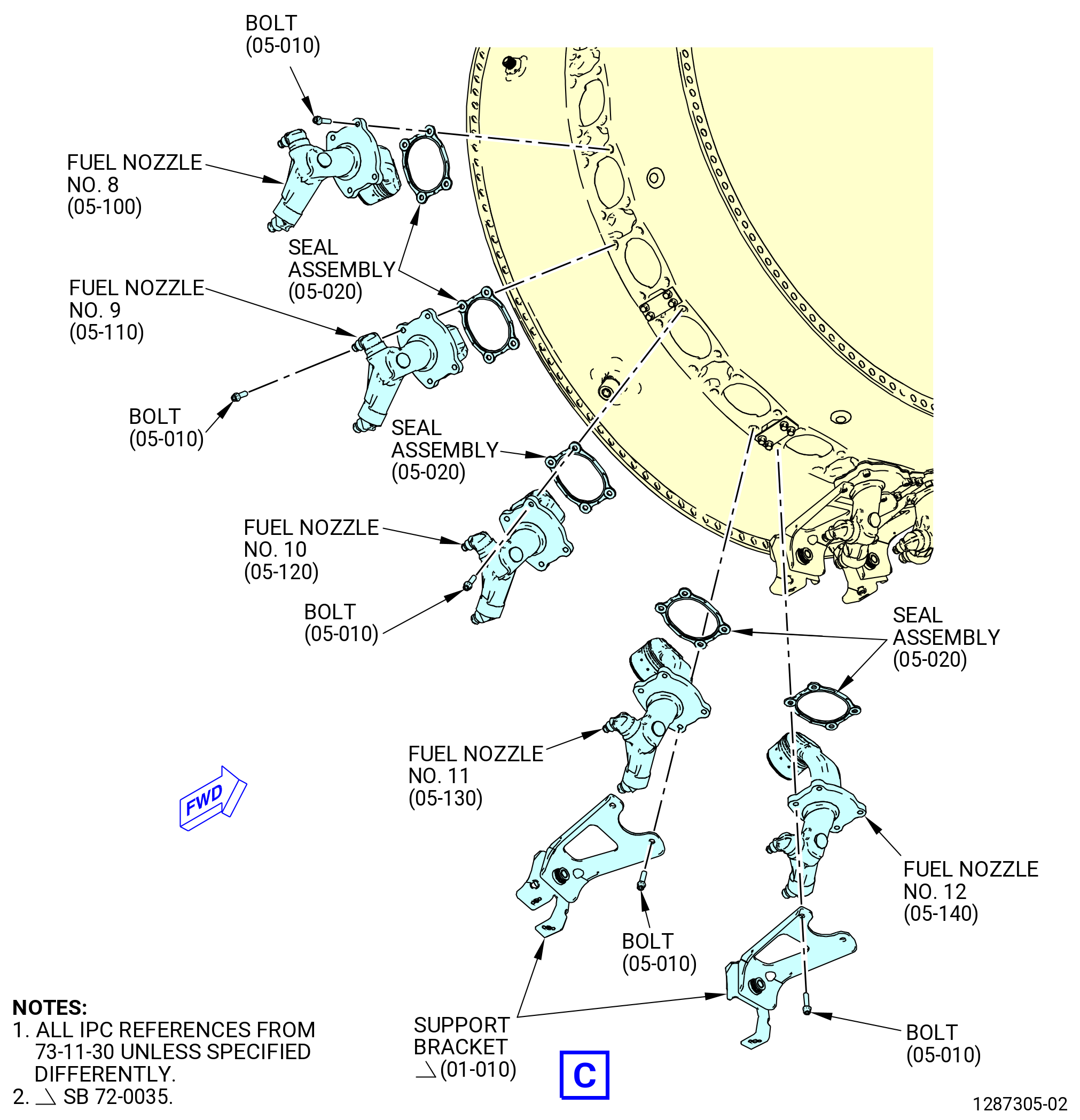
| (10) | Install the No. 8 fuel nozzle (05-100 , 73-11-30) (SIN 12500) in the combustor case as follows: |
| (a) | Make sure that the inner metal seal is in position on the seal assembly (05-020 , 73-11-30) (SIN 12550). |
| (b) | Install the fuel nozzle and the seal assembly on the combustor case. |
| (c) | Attach the fuel nozzle and the seal assembly to the combustor case with the bolts (05-010 , 73-11-30) (SIN 12520). Hand-tighten the bolts. Do not torque the bolts at this time. |
| CAUTION: |
|
| (d) | Do a visual inspection for the correct position of the fuel nozzle seal assembly as follows: |
| 1 | Make sure the four bolts (05-010 , 73-11-30) (SIN 12520) go through each seal assembly (05-020 , 73-11-30) (SIN 12550) bolthole. |
| (e) | Make sure that the fuel nozzle is inside the combustion chamber liner and radial mixer. |
| (11) | Install the No. 10 fuel nozzle (05-120 , 73-11-30) (SIN 12500) in the combustor case as follows: |
| (a) | Make sure that the inner metal seal is in position on the seal assembly (05-020 , 73-11-30) (SIN 12550). |
| (b) | Install the fuel nozzle and the seal assembly on the combustor case. |
| (c) | Attach the fuel nozzle and the seal assembly to the combustor case with the bolts (05-010 , 73-11-30) (SIN 12520). Hand-tighten the bolts. Do not torque the bolts at this time. |
| CAUTION: |
|
| (d) | Do a visual inspection for the correct position of the fuel nozzle seal assembly as follows: |
| 1 | Make sure the four bolts (05-010 , 73-11-30) (SIN 12520) go through each seal assembly (05-020 , 73-11-30) (SIN 12550) bolthole. |
| (e) | Make sure that the fuel nozzle is inside the combustion chamber liner and radial mixer. |
| (12) | Install the No. 11 fuel nozzle (05-130 , 73-11-30) (SIN 12500) in the combustor case as follows: |
| (a) | Make sure that the inner metal seal is in position on the seal assembly (05-020 , 73-11-30) (SIN 12550). |
| (b) | Install the fuel nozzle and the seal assembly on the combustor case. |
| (c) | Install the support bracket (01-010 , 73-11-30) (SIN 3411A) in the aft boltholes on top of the fuel nozzle. |
| (d) | Attach the fuel nozzle, the seal assembly, and the support bracket (01-010 , 73-11-30) (SIN 3411A) to the combustor case with the bolts (05-010 , 73-11-30) (SIN 12520). Hand-tighten the bolts. Do not torque the bolts at this time. |
| CAUTION: |
|
| (e) | Do a visual inspection for the correct position of the fuel nozzle seal assembly as follows: |
| 1 | Make sure the four bolts (05-010 , 73-11-30) (SIN 12520) go through each seal assembly (05-020 , 73-11-30) (SIN 12550) bolthole. |
| (f) | Make sure that the fuel nozzle is inside the combustion chamber liner and radial mixer. |
| (13) | Install the No. 9 fuel nozzle (05-110 , 73-11-30) (SIN 12500) in the combustor case as follows: |
| (a) | Make sure that the inner metal seal is in position on the seal assembly (05-020 , 73-11-30) (SIN 12550). |
| (b) | Install the fuel nozzle and the seal assembly on the combustor case. |
| (c) | Attach the fuel nozzle and the seal assembly to the combustor case with the bolts (05-010 , 73-11-30) (SIN 12520). Hand-tighten the bolts. Do not torque the bolts at this time. |
| CAUTION: |
|
| (d) | Do a visual inspection for the correct position of the fuel nozzle seal assembly as follows: |
| 1 | Make sure the four bolts (05-010 , 73-11-30) (SIN 12520) go through each seal assembly (05-020 , 73-11-30) (SIN 12550) bolthole. |
| (e) | Make sure that the fuel nozzle is inside the combustion chamber liner and radial mixer. |
| (14) | Install the No. 12 fuel nozzle (05-140 , 73-11-30) (SIN 12500) in the combustor case as follows: |
| (a) | Make sure that the inner metal seal is in position on the seal assembly (05-020 , 73-11-30) (SIN 12550). |
| (b) | Install the fuel nozzle and the seal assembly on the combustor case. |
| (c) | Install the support bracket (01-010 , 73-11-30) (SIN 3411A) in the aft boltholes on top of the fuel nozzle. |
| (d) | Attach the fuel nozzle, the seal assembly, and the support bracket (01-010 , 73-11-30) (SIN 3411A) to the combustor case with the bolts (05-010 , 73-11-30) (SIN 12520). Hand-tighten the bolts. Do not torque the bolts at this time. |
| CAUTION: |
|
| (e) | Do a visual inspection for the correct position of the fuel nozzle seal assembly as follows: |
| 1 | Make sure the four bolts (05-010 , 73-11-30) (SIN 12520) go through each seal assembly (05-020 , 73-11-30) (SIN 12550) bolthole. |
| (f) | Make sure that the fuel nozzle is inside the combustion chamber liner and radial mixer. |
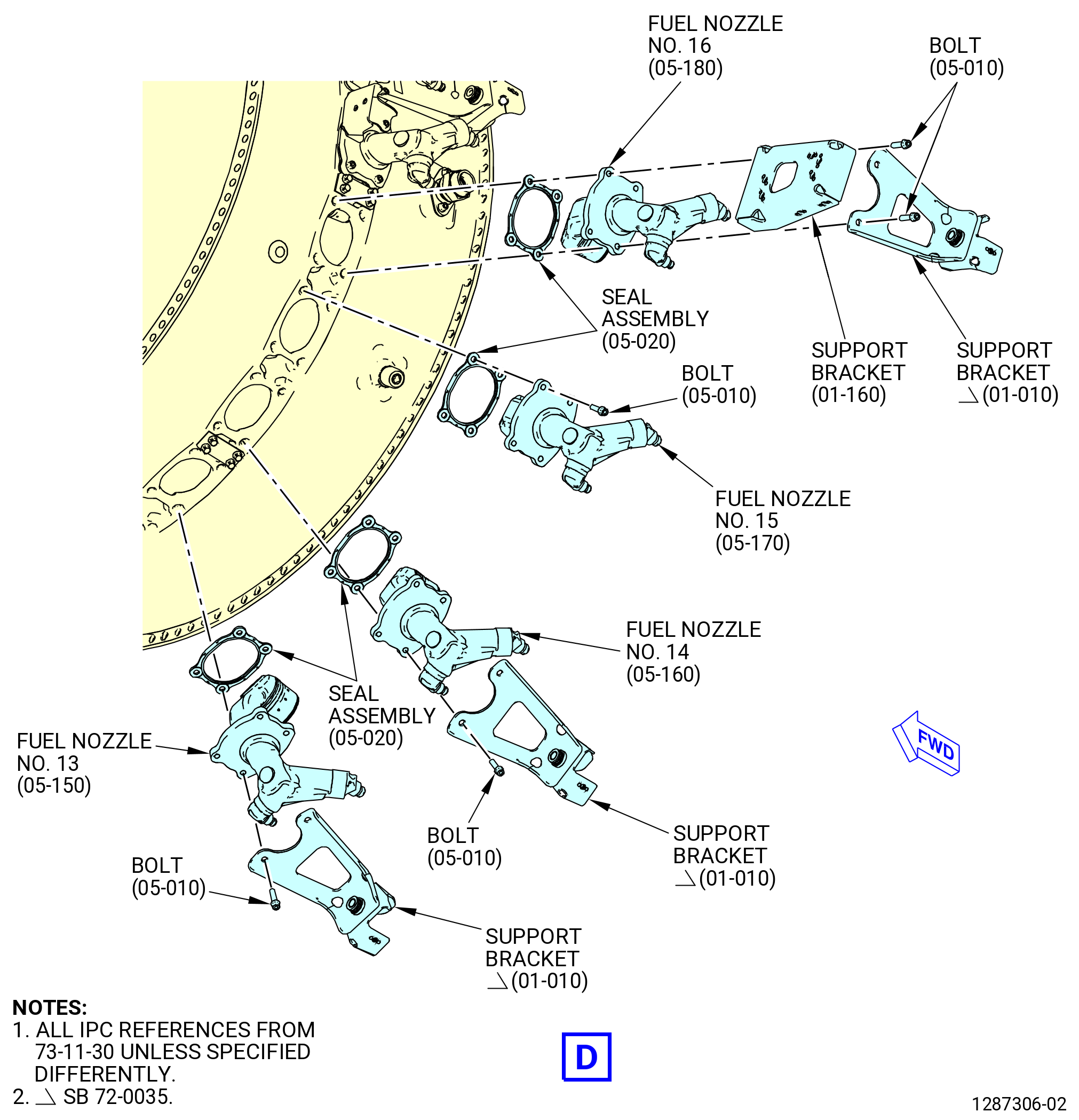
| (15) | Install the No. 13 fuel nozzle (05-150 , 73-11-30) (SIN 12500) in the combustor case as follows: |
| (a) | Make sure that the inner metal seal is in position on the seal assembly (05-020 , 73-11-30) (SIN 12550). |
| (b) | Install the fuel nozzle and the seal assembly on the combustor case. |
| (c) | Install the support bracket (01-010 , 73-11-30) (SIN 3411A) in the aft boltholes on top of the fuel nozzle. |
| (d) | Attach the fuel nozzle, the seal assembly, and the support bracket (01-010 , 73-11-30) (SIN 3411A) to the combustor case with the bolts (05-010 , 73-11-30) (SIN 12520). Hand-tighten the bolts. Do not torque the bolts at this time. |
| CAUTION: |
|
| (e) | Do a visual inspection for the correct position of the fuel nozzle seal assembly as follows: |
| 1 | Make sure the four bolts (05-010 , 73-11-30) (SIN 12520) go through each seal assembly (05-020 , 73-11-30) (SIN 12550) bolthole. |
| (f) | Make sure that the fuel nozzle is inside the combustion chamber liner and radial mixer. |
| (16) | Install the No. 14 fuel nozzle (05-160 , 73-11-30) (SIN 12500) in the combustor case as follows: |
| (a) | Make sure that the inner metal seal is in position on the seal assembly (05-020 , 73-11-30) (SIN 12550). |
| (b) | Install the fuel nozzle and the seal assembly on the combustor case. |
| (c) | Install the support bracket (01-010 , 73-11-30) (SIN 3411A) in the aft boltholes on top of the fuel nozzle. |
| (d) | Attach the fuel nozzle, the seal assembly, and the support bracket (01-010 , 73-11-30) (SIN 3411A) to the combustor case with the bolts (05-010 , 73-11-30) (SIN 12520). Hand-tighten the bolts. Do not torque the bolts at this time. |
| CAUTION: |
|
| (e) | Do a visual inspection for the correct position of the fuel nozzle seal assembly as follows: |
| 1 | Make sure the four bolts (05-010 , 73-11-30) (SIN 12520) go through each seal assembly (05-020 , 73-11-30) (SIN 12550) bolthole. |
| (f) | Make sure that the fuel nozzle is inside the combustion chamber liner and radial mixer. |
| (17) | Install the No. 15 fuel nozzle (05-170 , 73-11-30) (SIN 12500) in the combustor case as follows: |
| (a) | Make sure that the inner metal seal is in position on the seal assembly (05-020 , 73-11-30) (SIN 12550). |
| (b) | Install the fuel nozzle and the seal assembly on the combustor case. |
| (c) | Attach the fuel nozzle and the seal assembly to the combustor case with the bolts (05-010 , 73-11-30) (SIN 12520). Hand-tighten the bolts. Do not torque the bolts at this time. |
| (d) | Make sure that the fuel nozzle is inside the combustion chamber liner and radial mixer. |
| (18) | Install the No. 16 fuel nozzle (05-180 , 73-11-30) (SIN 12500) in the combustor case as follows: |
| (a) | Make sure that the inner metal seal is in position on the seal assembly (05-020 , 73-11-30) (SIN 12550). |
| (b) | Install the fuel nozzle and the seal assembly on the combustor case. |
| (c) | Install the support bracket (01-010 , 73-11-30) (SIN 3411A) in the aft boltholes and the stage 7 air support bracket (support bracket) (01-160 , 73-11-30) (SIN 6111A) in the fwd boltholes on top of the fuel nozzle. |
| (d) | Attach the fuel nozzle, the seal assembly, and the support brackets (01-010 , 73-11-30) (SIN 3411A) and (01-160 , 73-11-30) (SIN 6111A) to the combustor case with the bolts (05-010 , 73-11-30) (SIN 12520). Hand-tighten the bolts. Do not torque the bolts at this time. |
| CAUTION: |
|
| (e) | Do a visual inspection for the correct position of the fuel nozzle seal assembly as follows: |
| 1 | Make sure the four bolts (05-010 , 73-11-30) (SIN 12520) go through each seal assembly (05-020 , 73-11-30) (SIN 12550) bolthole. |
| (f) | Make sure that the fuel nozzle is inside the combustion chamber liner and radial mixer. |
| CAUTION: |
|
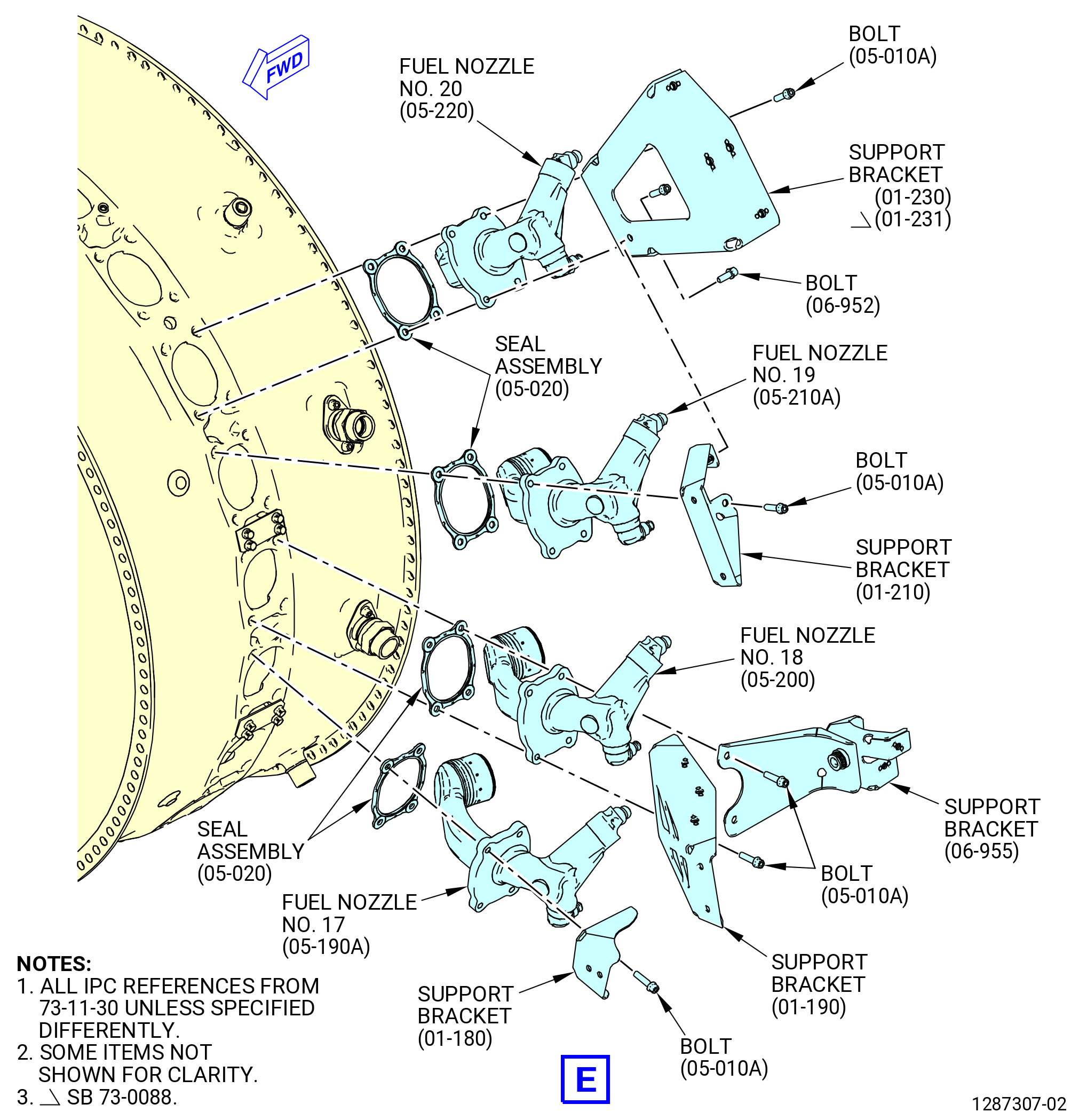
| (19) | Install the No. 17 fuel nozzle (05-190 , 73-11-30) (SIN 12501) in the combustor case as follows: |
| (a) | Make sure that the inner metal seal is in position on the seal assembly (05-020 , 73-11-30) (SIN 12550). |
| (b) | Install the fuel nozzle and the seal assembly on the combustor case. |
| (c) | Install the eductor support bracket (support bracket) (01-180 , 73-11-30) (SIN 61B18) in the fwd and aft boltholes at the 12:00 o'clock position on top of the fuel nozzle. |
| (d) | Attach the fuel nozzle, the seal assembly, and the support bracket (01-180 , 73-11-30) (SIN 61B18) to the combustor case with the bolts (05-010 , 73-11-30) (SIN 12520). Hand-tighten the bolts. Do not torque the bolts at this time. |
| CAUTION: |
|
| (e) | Do a visual inspection for the correct position of the fuel nozzle seal assembly as follows: |
| 1 | Make sure the four bolts (05-010 , 73-11-30) (SIN 12520) go through each seal assembly (05-020 , 73-11-30) (SIN 12550) bolthole. |
| (f) | Make sure that the fuel nozzle is inside the combustion chamber liner and radial mixer. |
| CAUTION: |
|
| (20) | Install the No. 18 fuel nozzle (05-200 , 73-11-30) (SIN 12501) in the combustor case as follows: |
| (a) | Make sure that the inner metal seal is in position on the seal assembly (05-020 , 73-11-30) (SIN 12550). |
| (b) | Install the fuel nozzle and the seal assembly on the combustor case. |
| (c) | Install the support bracket (01-190 , 73-11-30) (SIN 6221B) in the fwd boltholes and the fuel manifold bracket (support bracket) (01-030 , 73-11-20) (SIN 34118) in the aft boltholes on top of the fuel nozzle. |
| (d) | Attach the fuel nozzle, the seal assembly, and the support brackets (01-190 , 73-11-30) (SIN 6221B) and (01-030 , 73-11-30) (SIN 34118) to the combustor case with the bolts (05-010 , 73-11-30) (SIN 12520). Hand-tighten the bolts. Do not torque the bolts at this time. |
| CAUTION: |
|
| (e) | Do a visual inspection for the correct position of the fuel nozzle seal assembly as follows: |
| 1 | Make sure the four bolts (05-010 , 73-11-30) (SIN 12520) go through each seal assembly (05-020 , 73-11-30) (SIN 12550) bolthole. |
| (f) | Make sure that the fuel nozzle is inside the combustion chamber liner and radial mixer. |
| CAUTION: |
|
| (21) | Install the No. 19 fuel nozzle (05-210 , 73-11-30) (SIN 12501) in the combustor case as follows: |
| (a) | Make sure that the inner metal seal is in position on the seal assembly (05-020 , 73-11-30) (SIN 12550). |
| (b) | Install the fuel nozzle and the seal assembly on the combustor case. |
| (c) | Install the support bracket (01-210 , 73-11-30) (SIN 62116) in the right fwd bolthole at the 12:00 o'clock position on top of the fuel nozzle. |
| NOTE: |
|
| (d) | Attach the fuel nozzle, the seal assembly, and the support bracket (01-210 , 73-11-30) (SIN 62116) to the combustor case with the bolts (05-010 , 73-11-30) (SIN 12520). Hand-tighten the bolts. Do not torque the bolts at this time. |
| CAUTION: |
|
| (e) | Do a visual inspection for the correct position of the fuel nozzle seal assembly as follows: |
| 1 | Make sure the four bolts (05-010 , 73-11-30) (SIN 12520) go through each seal assembly (05-020 , 73-11-30) (SIN 12550) bolthole. |
| (f) | Make sure that the fuel nozzle is inside the combustion chamber liner and radial mixer. |
| CAUTION: |
|
| (22) | Install the No. 20 fuel nozzle (05-220 , 73-11-30) (SIN 12501) in the combustor case as follows: |
| (a) | Make sure that the inner metal seal is in position on the seal assembly (05-020 , 73-11-30) (SIN 12550). |
| (b) | Install the fuel nozzle and the seal assembly on the combustor case. |
| (c) | Install the support bracket (01-230 , 73-11-30) (SIN 61112) or (01-231 , 73-11-30) (SIN 61112) in the fwd boltholes on top of the fuel nozzle. |
| NOTE: |
|
| (d) | Attach the fuel nozzle, the seal assembly, and the support bracket to the combustor case with the bolts (05-010 , 73-11-30) (SIN 12520). Hand-tighten the bolts. Do not torque the bolts at this time. |
| CAUTION: |
|
| (e) | Do a visual inspection for the correct position of the fuel nozzle seal assembly as follows: |
| 1 | Make sure the four bolts (05-010 , 73-11-30) (SIN 12520) go through each seal assembly (05-020 , 73-11-30) (SIN 12550) bolthole. |
| (f) | Make sure that the fuel nozzle is inside the combustion chamber liner and radial mixer. |
| (23) | Install the No. 21 fuel nozzle (05-230 , 73-11-30) (SIN 12500) in the combustor case as follows: |
| (a) | Make sure that the inner metal seal is in position on the seal assembly (05-020 , 73-11-30) (SIN 12550). |
| (b) | Install the fuel nozzle and the seal assembly on the combustor case. |
| (c) | Install the support bracket (01-260 , 73-11-30) (SIN 34116) in the fwd boltholes on top of the fuel nozzle. |
| (d) | Attach the fuel nozzle, the seal assembly, and the support bracket (01-260 , 73-11-30) (SIN 34116) to the combustor case with the bolts (05-010 , 73-11-30) (SIN 12520). Hand-tighten the bolts. Do not torque the bolts at this time. |
| CAUTION: |
|
| (e) | Do a visual inspection for the correct position of the fuel nozzle seal assembly as follows: |
| 1 | Make sure the four bolts (05-010 , 73-11-30) (SIN 12520) go through each seal assembly (05-020 , 73-11-30) (SIN 12550) bolthole. |
| (f) | Make sure that the fuel nozzle is inside the combustion chamber liner and radial mixer. |
| (24) | Install the No. 22 fuel nozzle (05-240 , 73-11-30) (SIN 12500) in the combustor case as follows: |
| (a) | Make sure that the inner metal seal is in position on the seal assembly (05-020 , 73-11-30) (SIN 12550). |
| (b) | Install the fuel nozzle and the seal assembly on the combustor case. |
| (c) | Install the support bracket (01-010 , 73-11-30) (SIN 3411A) in the aft boltholes on top of the fuel nozzle. |
| (d) | Attach the fuel nozzle, the seal assembly, and the support bracket (01-010 , 73-11-30) (SIN 3411A) to the combustor case with the bolts (05-010 , 73-11-30) (SIN 12520). Hand-tighten the bolts. Do not torque the bolts at this time. |
| CAUTION: |
|
| (e) | Do a visual inspection for the correct position of the fuel nozzle seal assembly as follows: |
| 1 | Make sure the four bolts (05-010 , 73-11-30) (SIN 12520) go through each seal assembly (05-020 , 73-11-30) (SIN 12550) bolthole. |
| (f) | Make sure that the fuel nozzle is inside the combustion chamber liner and radial mixer. |
| (25) | Secure the support bracket (01-210 , 73-11-30) (SIN 62116) and the support bracket (01-230 , 73-11-30) (SIN 61112) or (01-231 , 73-11-30) (SIN 61112) as follows: |
| (a) | Attach the two support brackets (01-210 , 73-11-30) (SIN 62116) and (01-230 , 73-11-30) (SIN 61112) or (01-231 , 73-11-30) (SIN 61112) with a bolt (01-250 , 73-11-30) (SIN 62124). |
| (b) | Torque the bolt (01-250 , 73-11-30) (SIN 62124) to 138 to 162 lb in. (15.6 to 18.3 Nm). |
| Subtask 72-40-00-440-159 |
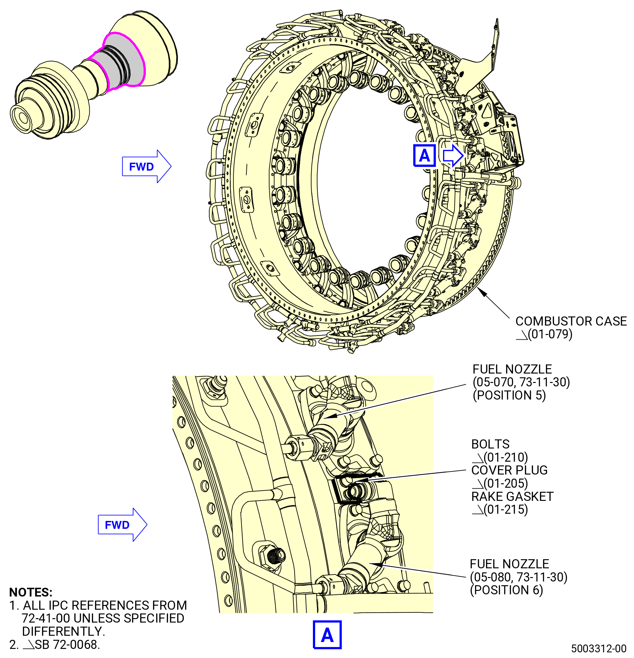
| * * * SB 72-0068( Combustor Case with Rake Pad ) |
| (26) | If necessary, install the cover plug (01-205 , 72-41-00) (SIN 65N01). Refer to Figure 1022 and do as follows: |
| NOTE: |
|
| WARNING: |
|
| (a) | Lubricate the threads of the four machine bolts (bolts) (01-210 , 72-41-00) (SIN 65N20) with C02-058 lubricant or C02-097 lubricant. |
| (b) | Install the cover plug and the rake gasket (01-215 , 72-41-00) (SIN 65N50) on the combustor case (01-079 , 72-41-00) (SIN 12001) with four bolts (01-210 , 72-41-00) (SIN 65N20) between the fuel nozzle (05-070 , 73-11-30) (SIN 12500) (position 5) and fuel nozzle (05-080 , 73-11-30) (SIN 12500) (position 6). |
| NOTE: |
|
| (c) | Torque the bolts in a criss-cross pattern to 106-124 lb in. (12.0-14.0 N.m). |
| (d) | Safety the bolts with C10-071 safety wire or C10-143 safety cable. |
| * * * END SB 72-0068 |
|
| Subtask 72-40-00-440-107 |
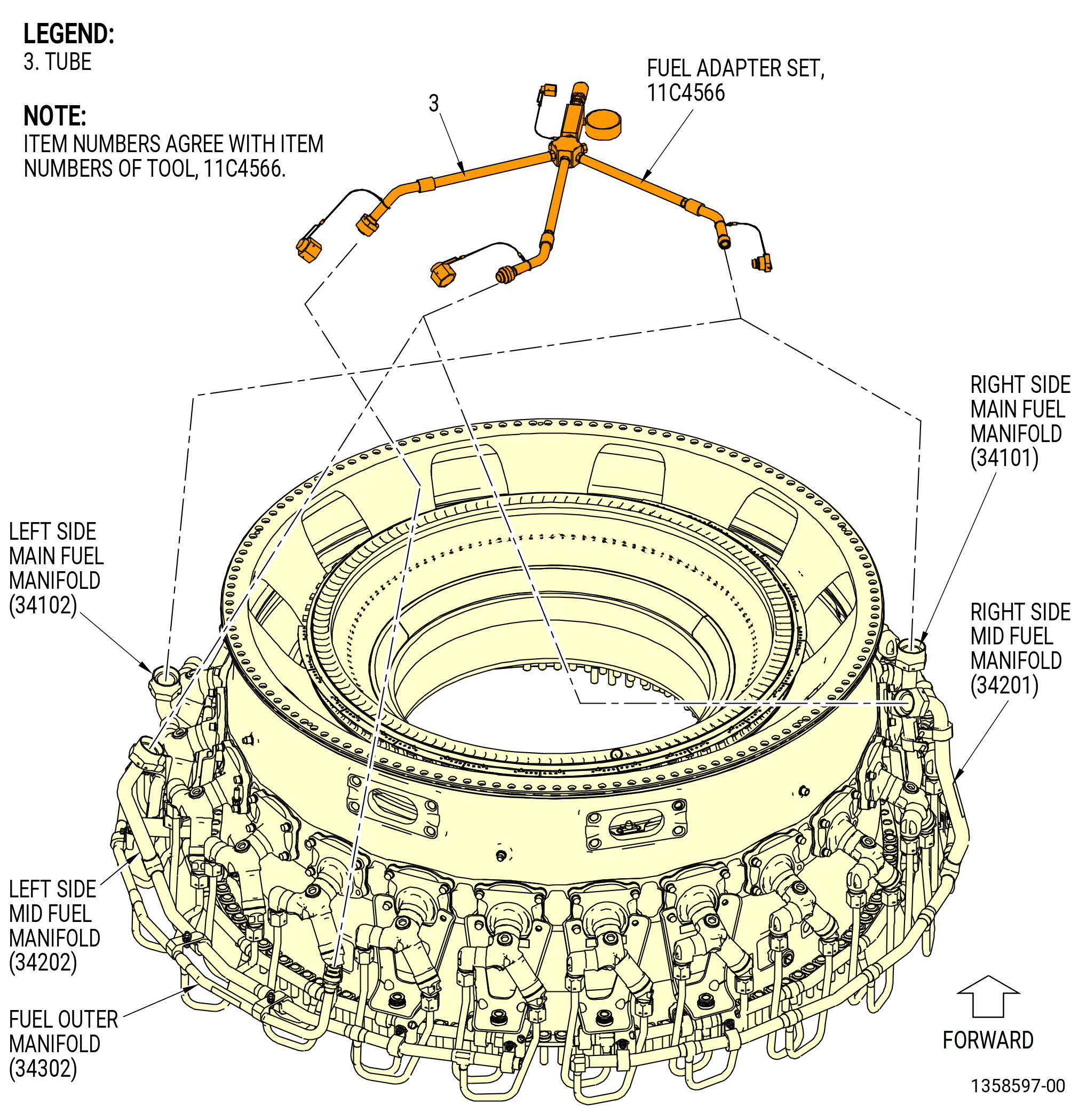
| R. | Install the fuel manifolds (34101, 34102) as follows: |
| (1) | Apply C02-033 petrolatum to the new preformed packings (10-080 , 73-11-40) (SIN 12551). Refer to Figure 1023. |
| (2) | Install the two new preformed packings (10-080 , 73-11-40) (SIN 12551) on each fuel nozzle (12500) and (12501). |
| (3) | Prepare the fuel manifolds (34101, 34102) for installation as follows: |
| (a) | Put the fuel manifolds with the coupling nuts vertical on a clean table. |
| (b) | Remove the protective caps from the manifold coupling nuts. |
| (c) | Make sure that the fuel manifold coupling nuts are free to move and do not have thread damage. |
| (d) | Put C02-033 petrolatum on the lead-in chamfers of the fuel manifold fittings. |
| (4) | Install the fuel manifold (34101) as follows. Refer to Figure 1024. |
| (a) | Loosely connect the coupling nuts of the manifold to fuel nozzles No. 2 thru No. 12. |
| (5) | Install the fuel manifold (34102) as follows: |
| (a) | Loosely connect the coupling nuts of the manifold to fuel nozzles No. 13 thru No. 1. |
| Subtask 72-40-00-440-191 |
| * * * PRE SB 73-0075( Fuel Manifold without Split Bushing ) |
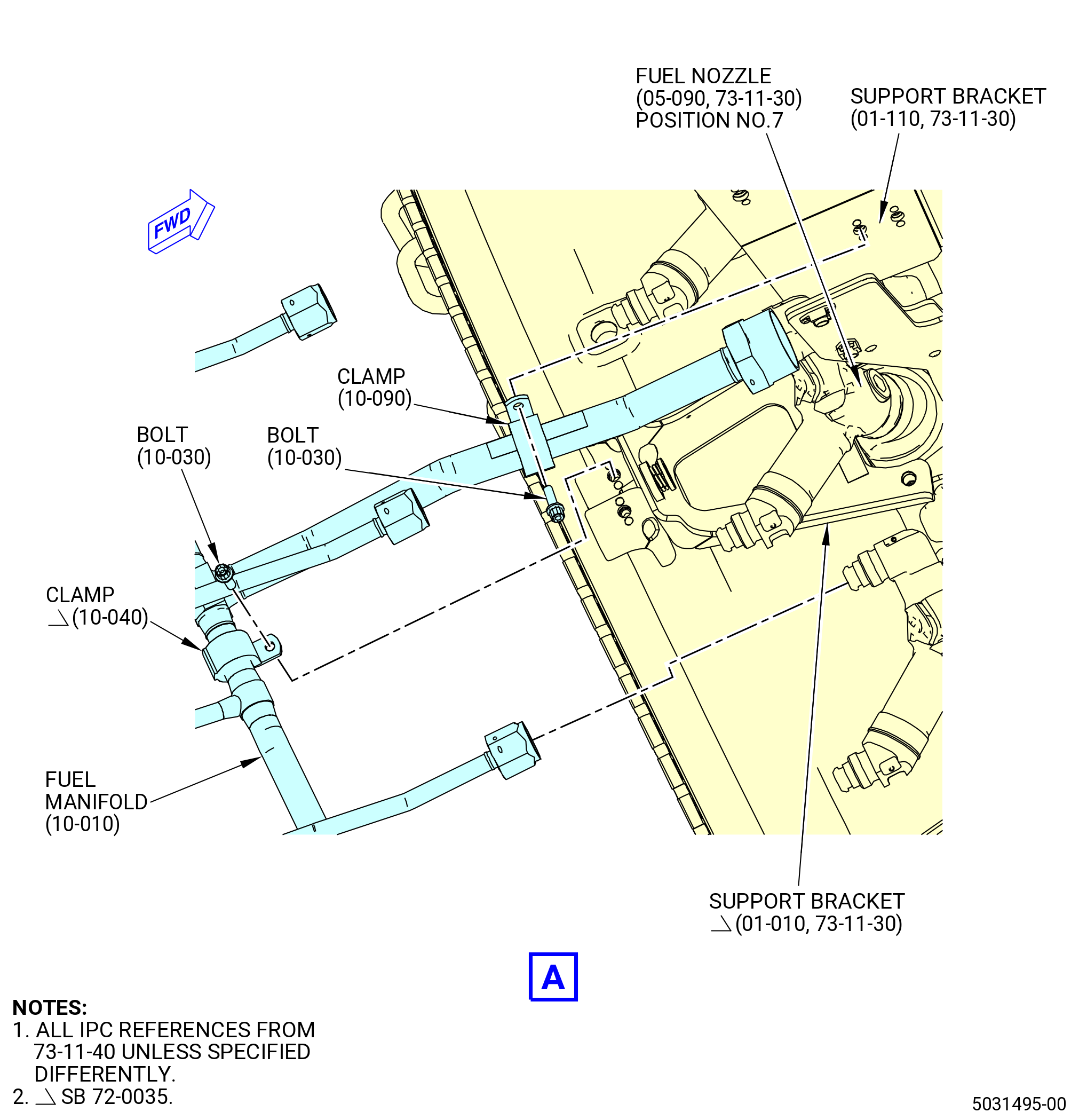
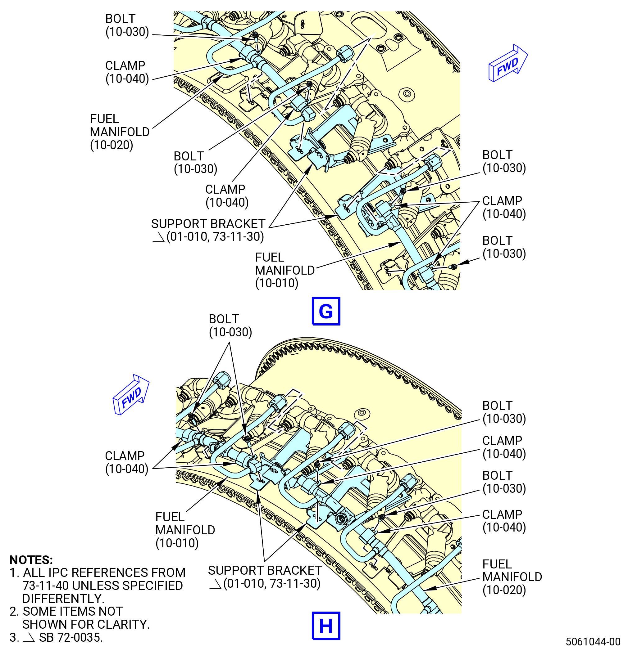
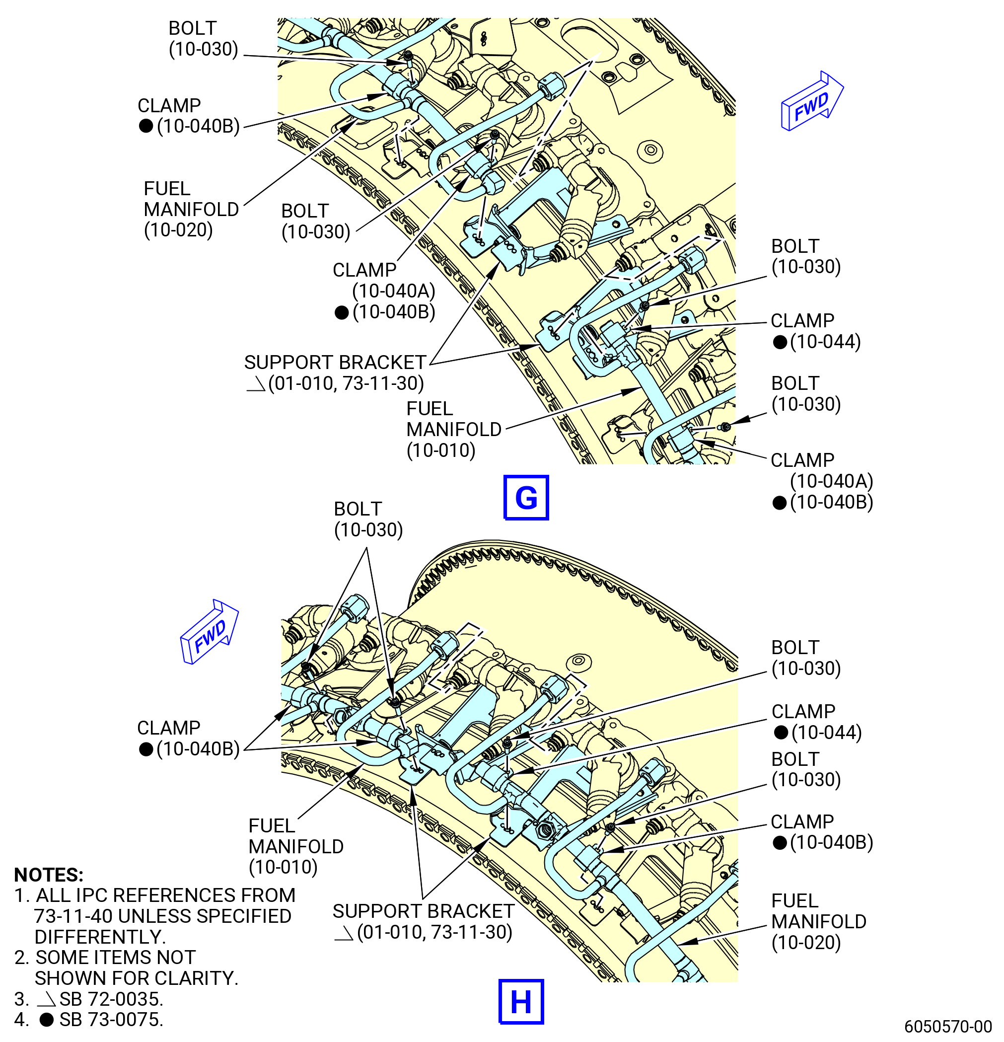
| (6) | Install the cushion loop clamps (clamps) (10-040 , 73-11-40) (SIN 34180) and (10-090 , 73-11-40) (SIN 34181) as follows: |
| (a) | Deleted. |
| (b) | Install 10 clamps (10-040 , 73-11-40) (SIN 34180) on the fuel manifolds (10-010 , 73-11-40) (SIN 34101) and (10-020 , 73-11-40) (SIN 34102) and one clamp (10-090 , 73-11-40) (SIN 34181) on the fuel manifold (10-010 , 73-11-40) (SIN 34101). |
| (c) | Safety the clamps (10-040 , 73-11-40) (SIN 34180) and (10-090 , 73-11-40) (SIN 34181) with 11 bolts (10-030 , 73-11-40) (SIN 34120). |
| (d) | Do not torque the bolts (10-030 , 73-11-40) (SIN 34120) at this time. |
| * * * END PRE SB 73-0075 |
| Subtask 72-40-00-440-192 |
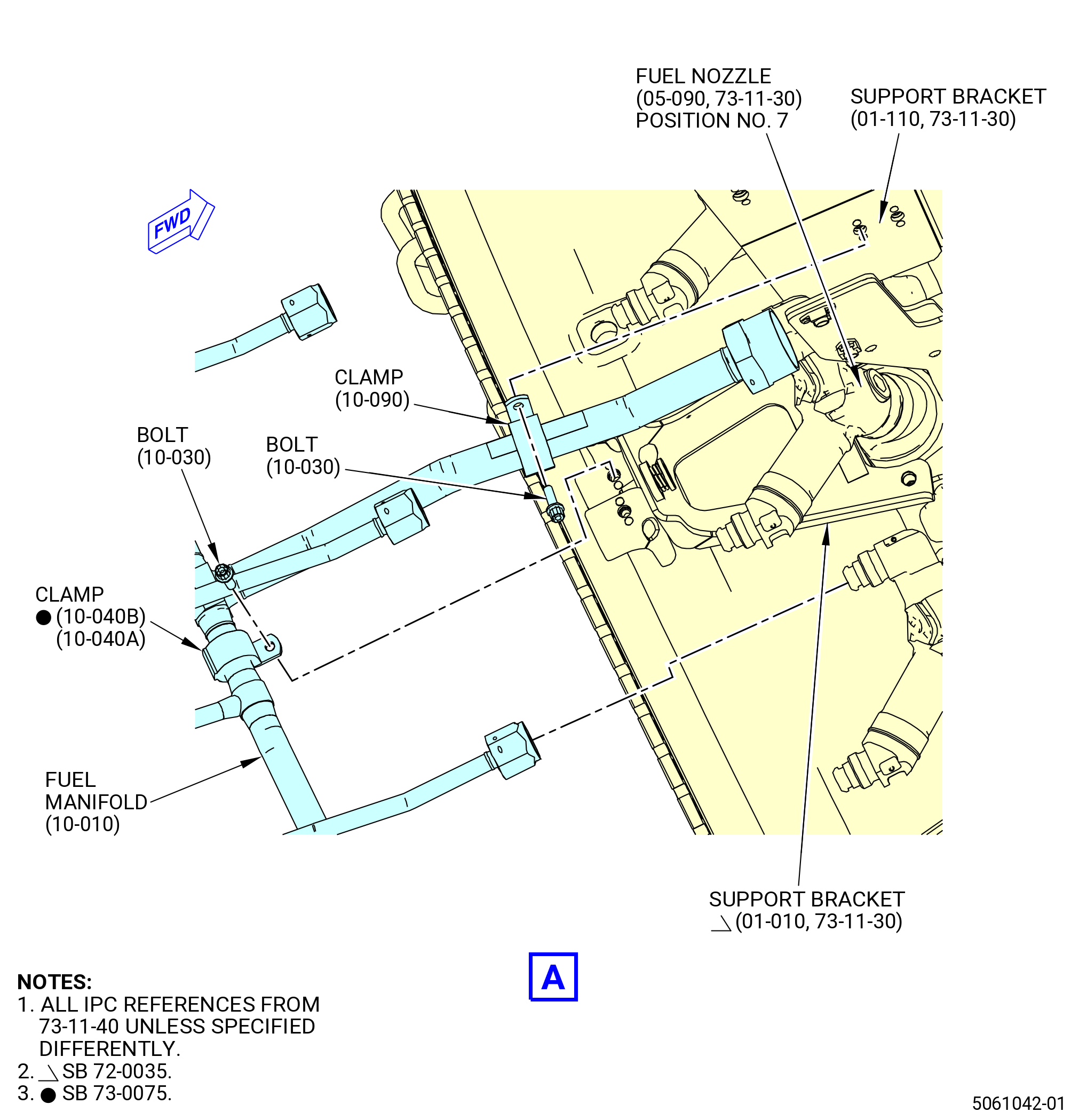
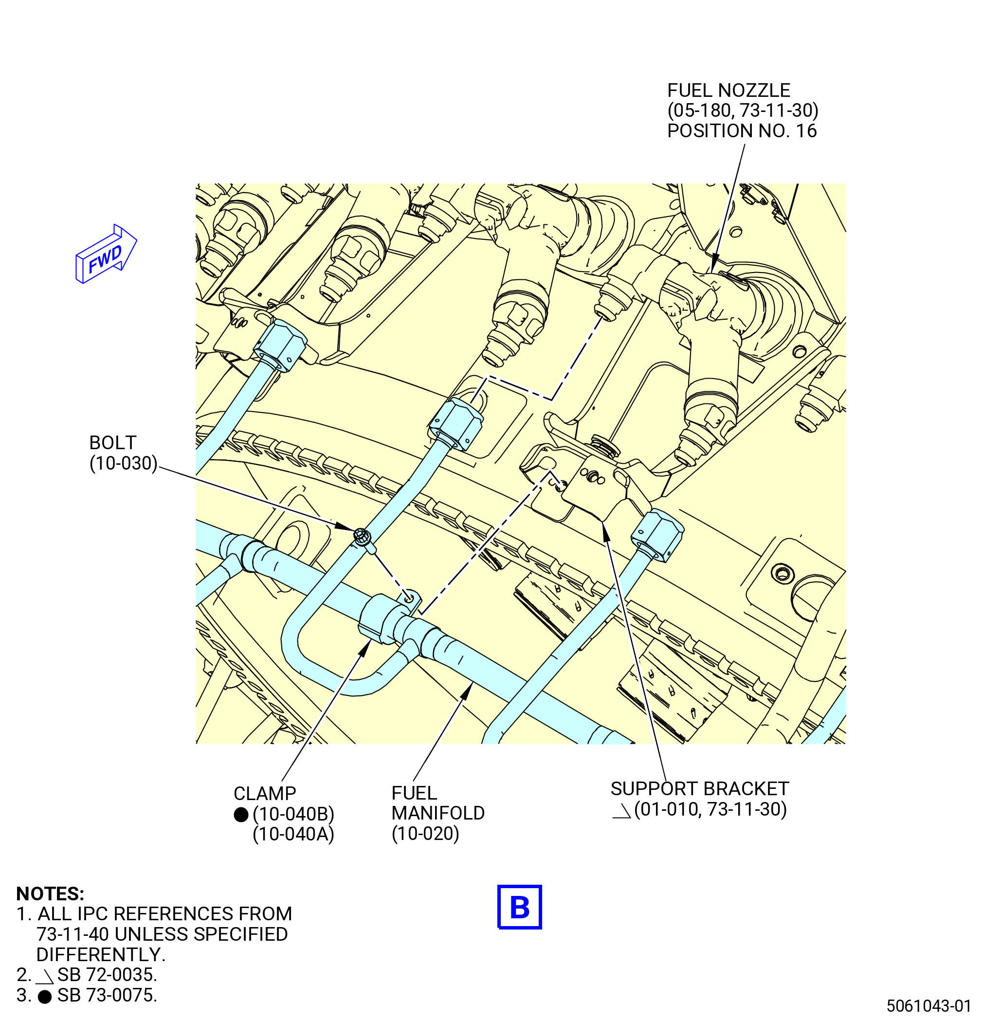
| * * * SB 73-0075( Fuel Manifold with Split Bushing or with Split Bushing and Cushion Clamps ) |
| (6).A. | Install the clamps (10-040B , 73-11-40) (SIN 34180), or (10-040A , 73-11-40) (SIN 34180), (10-043A , 73-11-40) (SIN 3428G), or (10-044 , 73-11-40) (SIN 3428G), and (10-090 , 73-11-40) (SIN 34181) as follows: |
| (a) | Install nine clamps (10-040B , 73-11-40) (SIN 34180) or 11 clamps (10-040A , 73-11-40) (SIN 34180) on the fuel manifolds (10-010 , 73-11-40) (SIN 34101) and (10-020 , 73-11-40) (SIN 34102) and one clamp (10-090 , 73-11-40) (SIN 34181) on the fuel manifold (10-010 , 73-11-40) (SIN 34101). |
| (b) | For split bushing configuration, install four split bushings (10-045 , 73-11-40) (SIN 34270) on the fuel manifolds (10-010 , 73-11-40) (SIN 34101) and (10-020 , 73-11-40) (SIN 34102). |
| (c) | Install two clamps (10-043A , 73-11-40) (SIN 3428G) or (10-044 , 73-11-40) (SIN 3428G) for split bushing configuration use two brackets (10-047 , 73-11-40) (SIN 342E0), on the fuel manifolds (10-010 , 73-11-40) (SIN 34101) and (10-020 , 73-11-40) (SIN 34102). |
| (d) | Safety the clamps (10-040B , 73-11-40) (SIN 34180), (10-043A , 73-11-40) (SIN 3428G) and (10-090 , 73-11-40) (SIN 34181) with 12 bolts (10-030 , 73-11-40) (SIN 34120). |
| (e) | Do not torque the bolts (10-030 , 73-11-40) (SIN 34120) at this time. |
| * * * END SB 73-0075 |
| Subtask 72-40-00-440-193 |
| (7) | Install the inner right hand fuel manifold (fuel manifold) (34201) as follows: |
| (a) | Lubricate the lead-in chamfers of the fuel manifold with C02-033 petrolatum. |
| (b) | Install the fuel manifold (34201) on the fuel nozzles No. 2 thru No. 12. |
| (8) | Install the inner left hand fuel manifold (fuel manifold) (34202) as follows: |
| (a) | Lubricate the lead-in chamfers of the fuel manifold with C02-033 petrolatum. |
| (b) | Install the fuel manifold (34202) on the fuel nozzles No. 13 thru No. 16 and from No. 21 thru No. 1. |
| Subtask 72-40-00-440-194 |
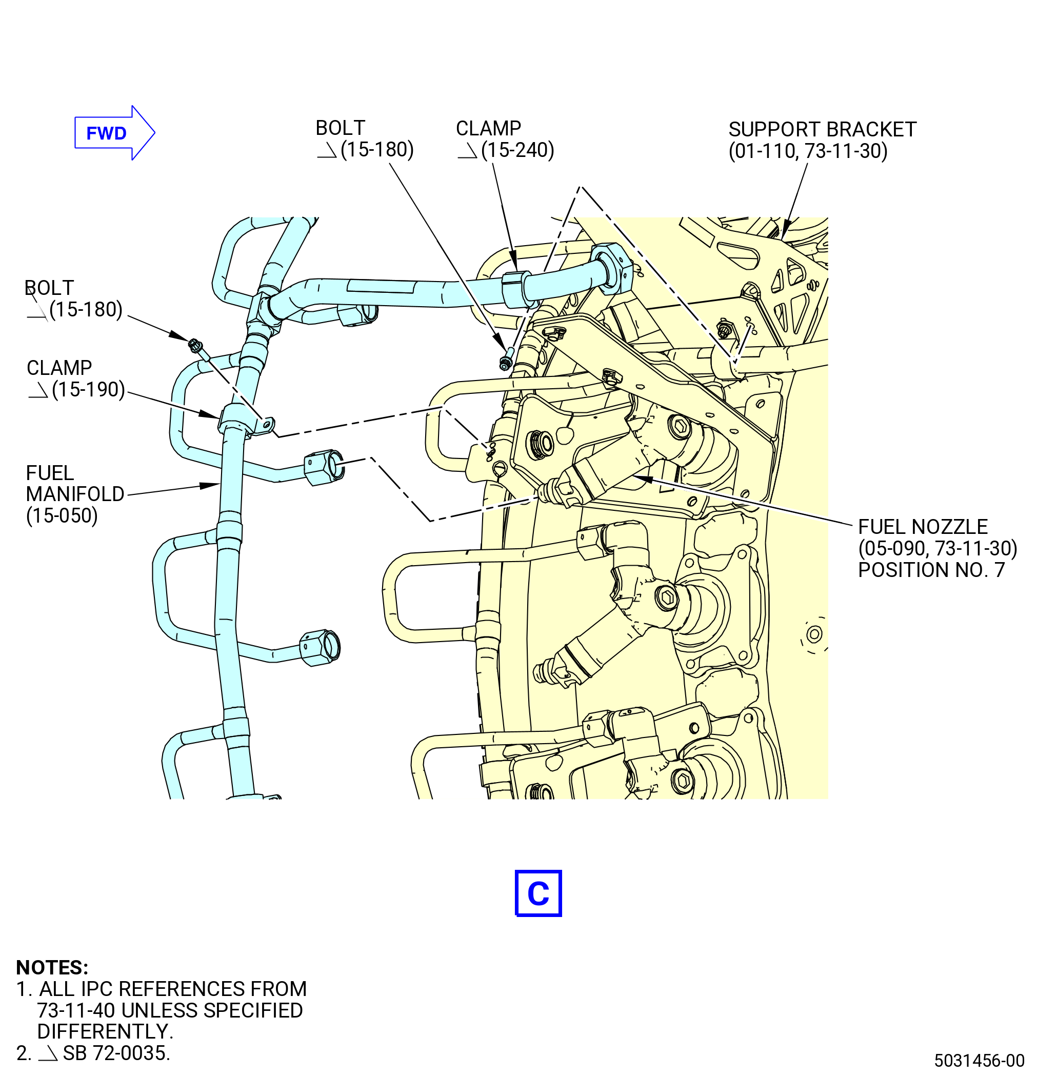
| * * * PRE SB 73-0075( Fuel Manifold without Split Bushing ) |
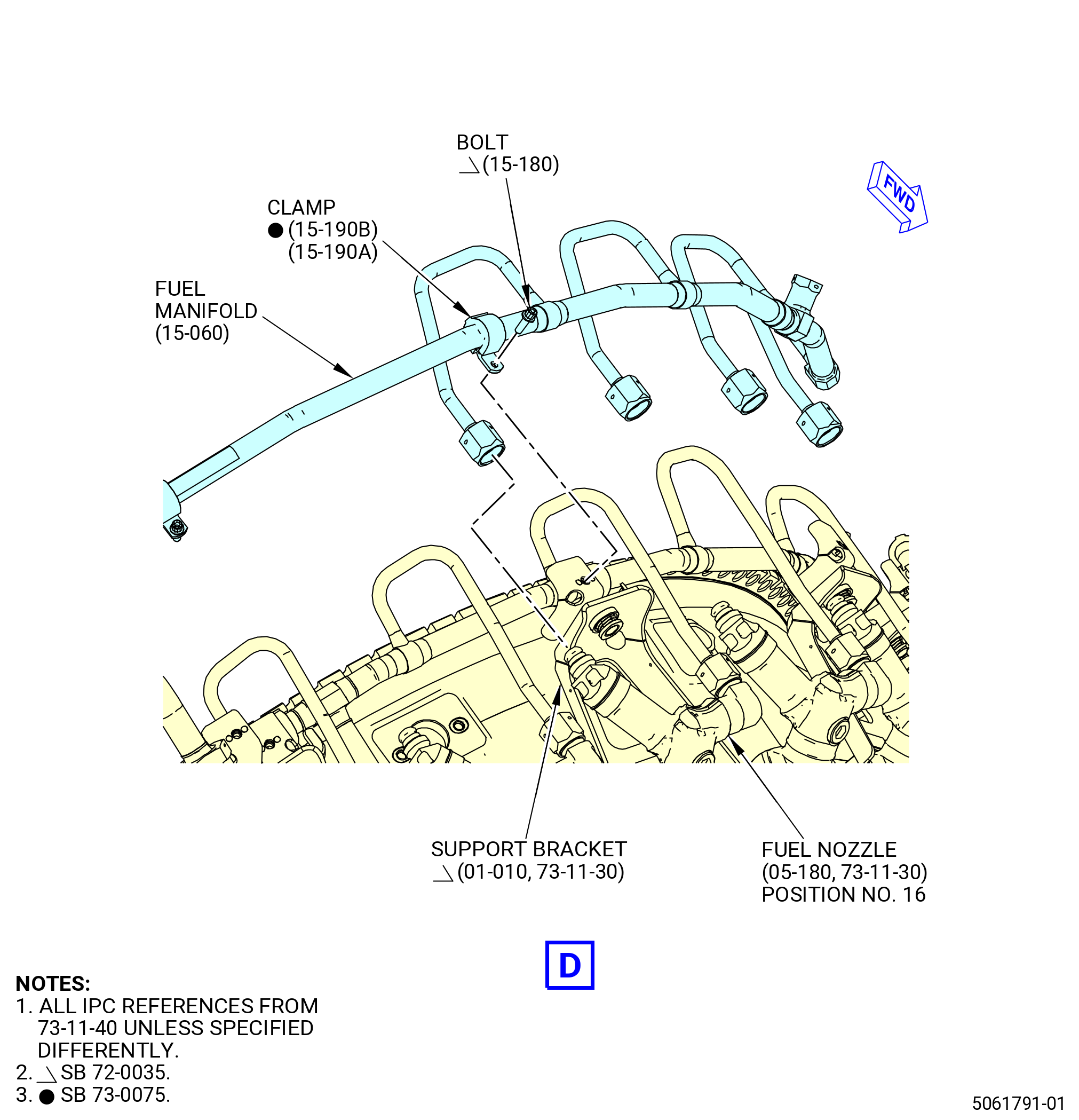
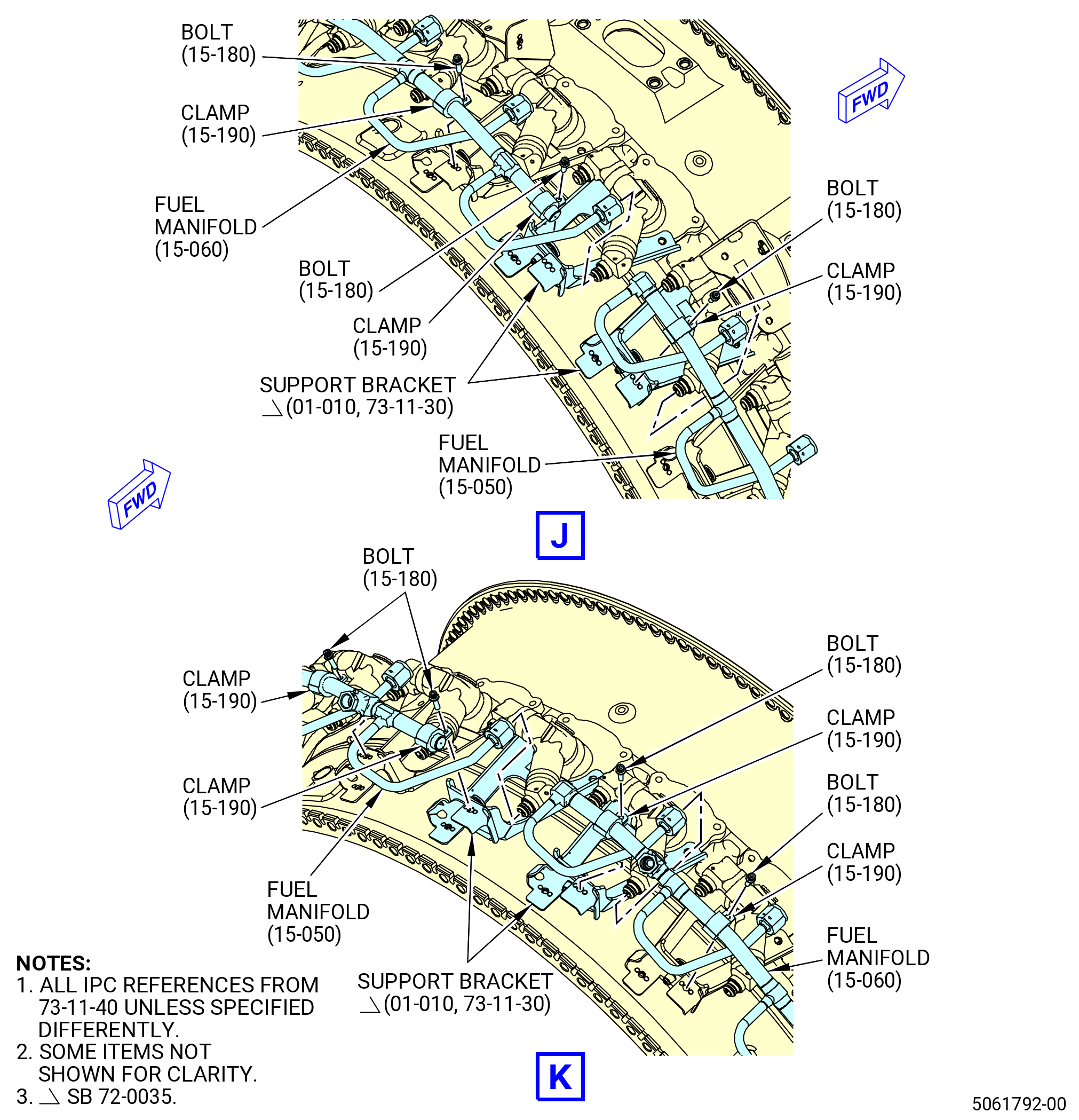
| (9) | Install the cushion loop clamps (clamps) (15-190 , 73-11-40) (SIN 34280) and (15-240 , 73-11-40) (SIN 34281) as follows: |
| (a) | Deleted. |
| (b) | Install 10 clamps (15-190 , 73-11-40) (SIN 34280) and one clamp (15-240 , 73-11-40) (SIN 34281) on the fuel manifolds (15-050 , 73-11-40) (SIN 34201) and (15-060 , 73-11-40) (SIN 34202). |
| (c) | Safety the clamps (15-190 , 73-11-40) (SIN 34280) and (15-240 , 73-11-40) (SIN 34281) with 11 bolts (15-180 , 73-11-40) (SIN 34220). |
| (d) | Do not torque the bolts (15-180 , 73-11-40) (SIN 34220) at this time. |
| * * * END PRE SB 73-0075 |
| Subtask 72-40-00-440-195 |
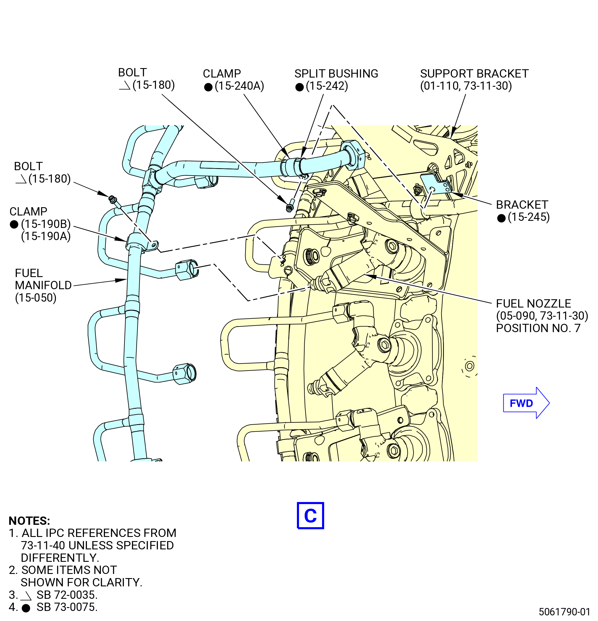
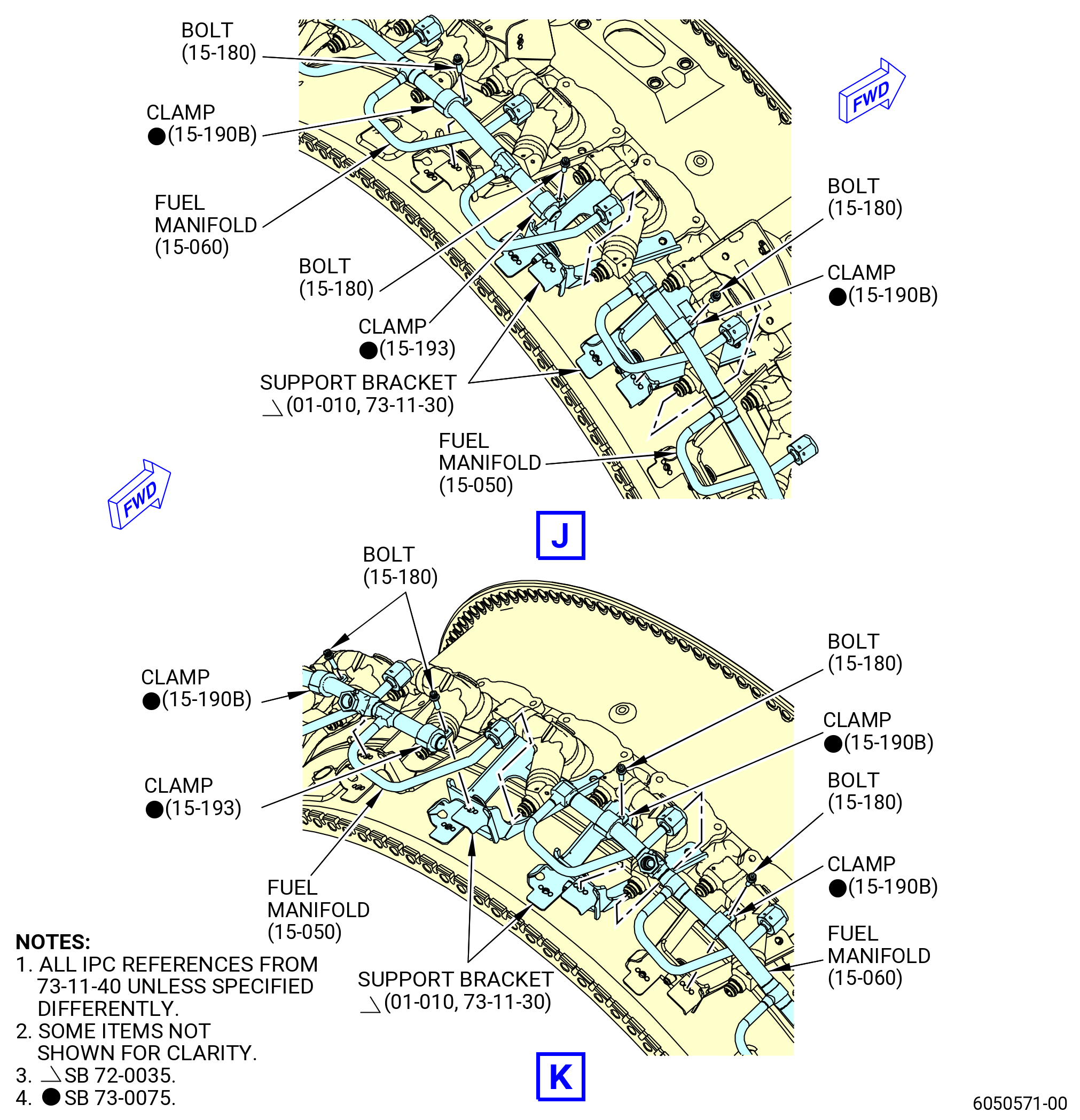
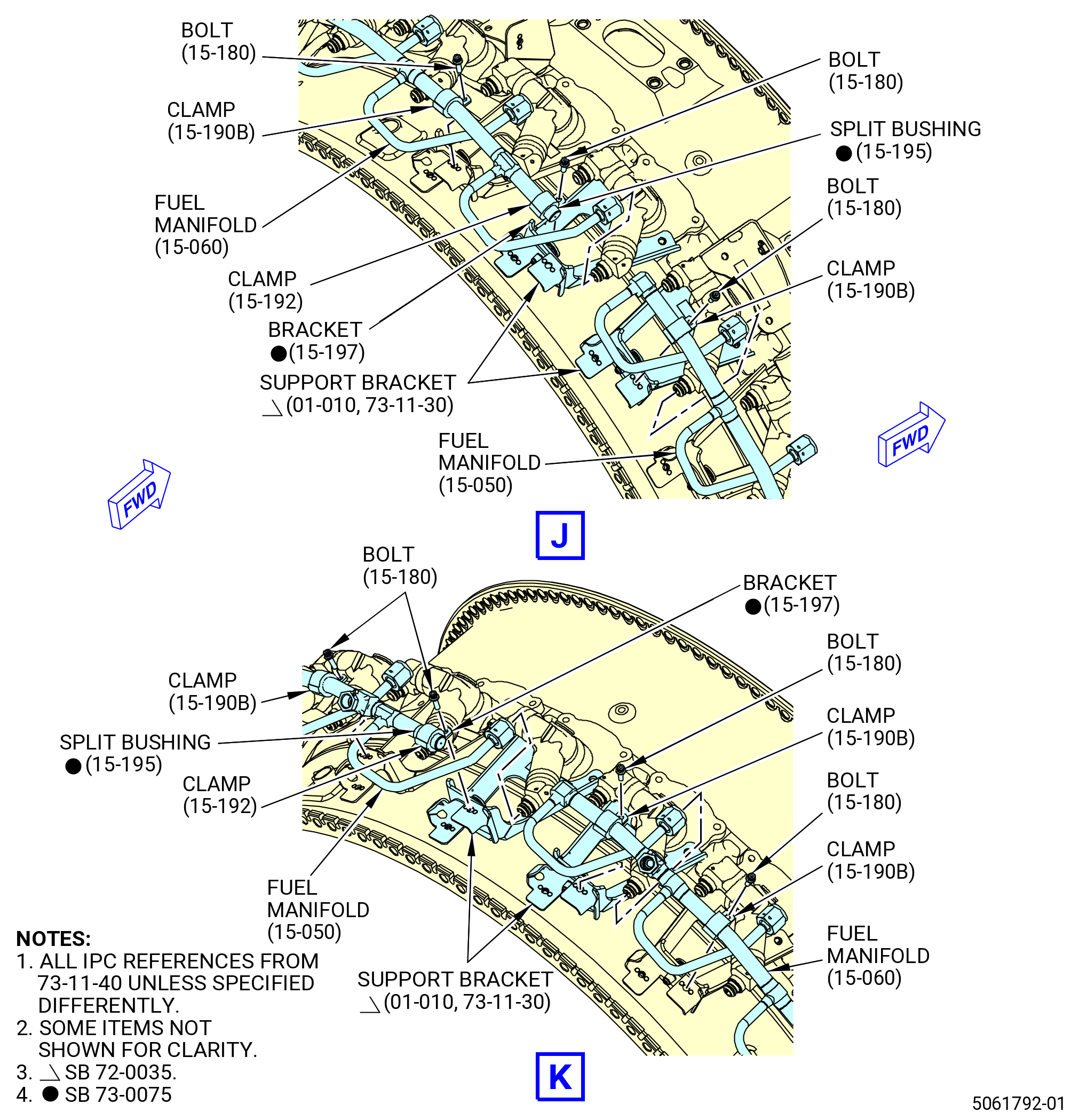
| * * * SB 73-0075( Fuel Manifold with Split Bushing or with Split Bushing and Cushion Clamps ) |
| (9).A. | Install the clamps (15-190B , 73-11-40) (SIN 34280) and (15-193 , 73-11-40) (SIN 3428G), or (15-190A , 73-11-40) (SIN 34280), (15-240A , 73-11-40) (SIN 34281) and (15-192 , 73-11-40) (SIN 3428G) as follows: |
| (a) | Install the 12 clamps (15-190B , 73-11-40) (SIN 34280) or 14 clamps (15-190A , 73-11-40) (SIN 34280) on fuel manifolds (15-050 , 73-11-40) (SIN 34201) and (15-060 , 73-11-40) (SIN 34202). |
| (b) | For split bushing configuration, install four split bushings (15-195 , 73-11-40) (SIN 34270) on fuel manifolds (15-050 , 73-11-40) (SIN 34201) and (15-060 , 73-11-40) (SIN 34202). For split bushing, split bushing and cushioning clamp configurations, install two split bushings (15-242 , 73-11-40) (SIN 34271) on the fuel manifold (15-050 , 73-11-40) (SIN 34201). |
| (c) | Install two clamps (15-192 , 73-11-40) (SIN 3428G) or (15-193 , 73-11-40) (SIN 3428G), and one clamp (15-240A , 73-11-40) (SIN 34281). For split bushing configuration, install two brackets (15-197 , 73-11-40) (SIN 342E0) on fuel manifolds (15-050 , 73-11-40) (SIN 34201) and (15-060 , 73-11-40) (SIN 34202). For split bushing, split bushing and cushioning clamp configurations, install one bracket (15-185 , 73-11-40) (SIN 341E1) on the fuel manifold (15-050 , 73-11-40) (SIN 34201). |
| (d) | Safety the clamps (15-190B , 73-11-40) (SIN 34280), or (15-190A , 73-11-40) (SIN 34280), (15-192 , 73-11-40) (SIN 3428G) or (15-193 , 73-11-40) (SIN 3428G) and (15-240A , 73-11-40) (SIN 34281) with 15 bolts (15-180 , 73-11-40) (SIN 34220). |
| (e) | Do not torque the bolts (15-180 , 73-11-40) (SIN 34220) at this time. |
| * * * END SB 73-0075 |
| Subtask 72-40-00-440-196 |
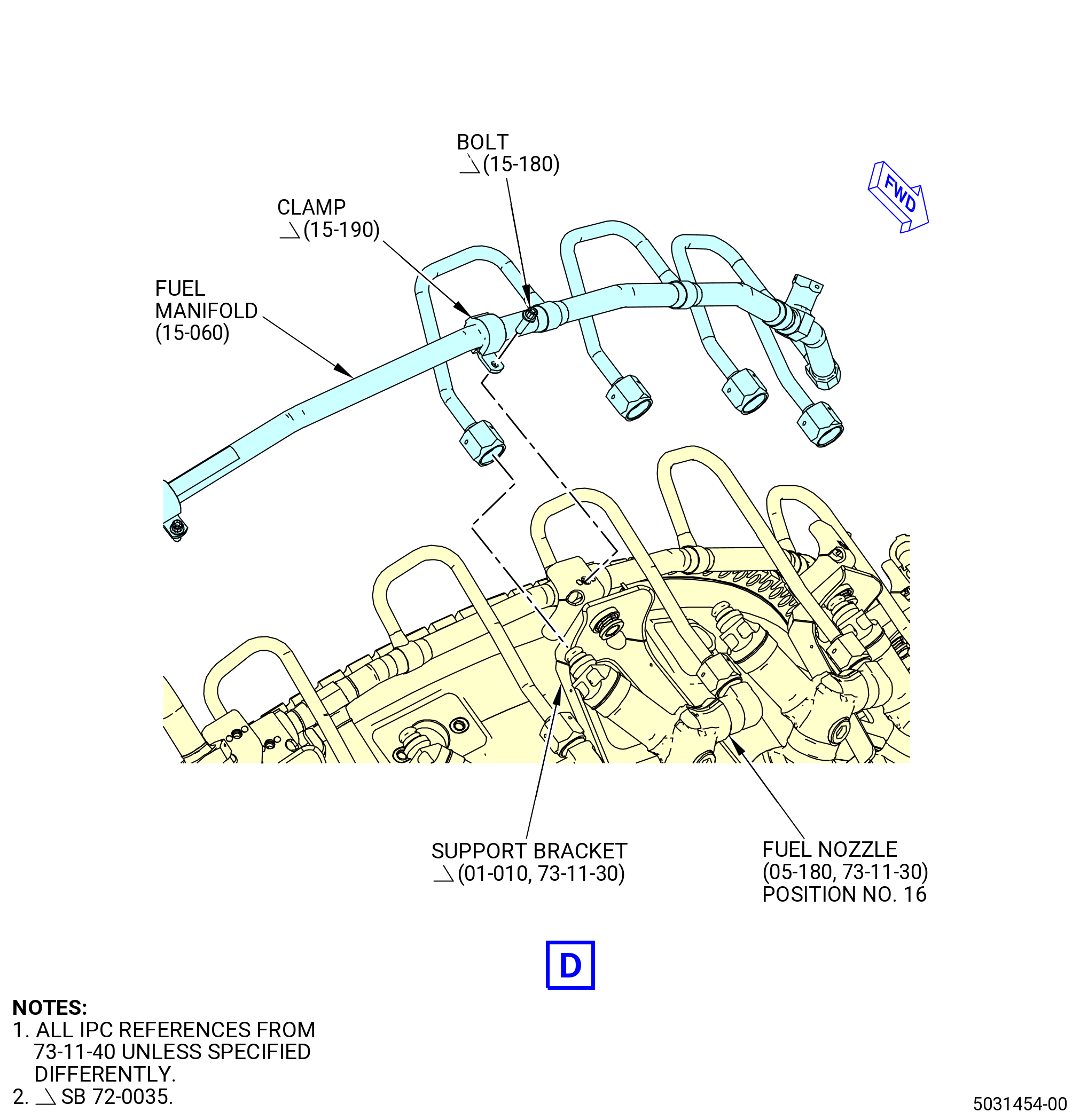
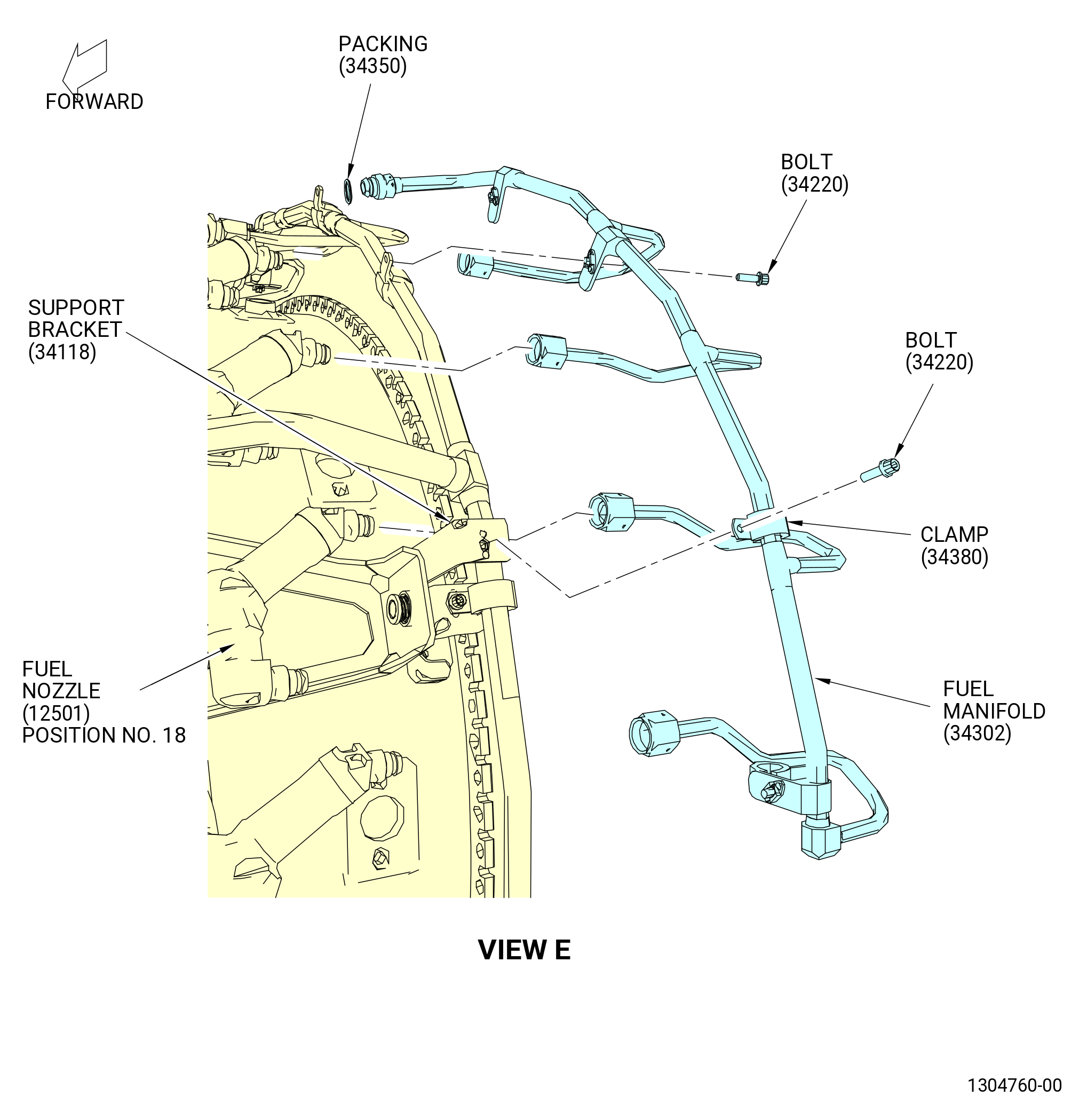
| (10) | Install the outer left hand fuel manifold (fuel manifold) (34302) as follows: |
| (a) | Lubricate the lead-in chamfers of the fuel manifold with C02-033 petrolatum. |
| (b) | Install the fuel manifold (34302) on the fuel nozzles No. 17 thru No. 20. |
| (11) | Install the cushion loop clamps (clamps) (15-190 , 73-11-40) (SIN 34280) and (15-140 , 73-11-40) (SIN 34380) as follows: |
| (a) | Deleted. |
| (b) | Install one clamp (15-140 , 73-11-40) (SIN 34380) and three clamps (15-190 , 73-11-40) (SIN 34280) on the fuel manifold (15-040 , 73-11-40) (SIN 34302). |
| (c) | Safety the clamp (15-140 , 73-11-40) (SIN 34380) with one bolt (15-130 , 73-11-40) (SIN 34320) and clamps (15-190 , 73-11-40) (SIN 34280) with three bolts (15-180 , 73-11-40) (SIN 34220). |
| (d) | Do not torque the bolts (15-130 , 73-11-40) (SIN 34320) and (15-180 , 73-11-40) (SIN 34220) at this time. |
| (12) | Install the preformed packing (packing) (34350) as follows: |
| (a) | Lubricate the packing (34350) with C02-033 petrolatum. |
| (b) | Install the packing (34350) in the fuel manifold (34302). |
| (13) | Tighten the bolts (05-010 , 73-11-30) (SIN 12520) that attach the fuel nozzles and brackets to the combustor case to seat them as follows: |
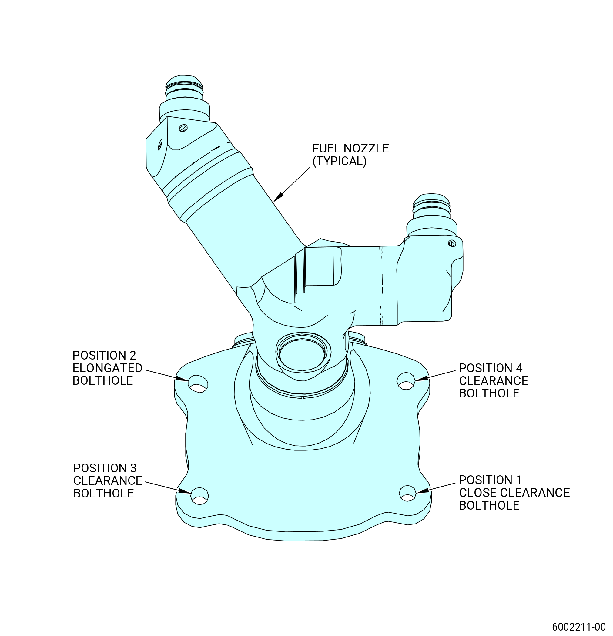
| (a) | Tighten the fuel nozzle bolts (05-010 , 73-11-30) (SIN 12520) to 135 to 140 lb in. (15.2 to 15.8 Nm). Follow the torquing sequence for each fuel nozzle bolt starting with position 1 (close clearance bolthole), then torque position 2 (elongated bolthole), then position 3 (clearance bolthole) and ending with position 4 (clearance bolthole). Refer to Figure 1020. |
| (14) | Do a seal assembly shim check as follows: |
| (a) | Use a Feeler Gauge, STD-5468 and set the gauge shim stock to 0.005 in. (0.13 mm). |
| (b) | Put the 0.005 in. (0.13 mm) gauge shim stock between the combustion case port and the seal assembly or between the fuel nozzle mounting flange and the seal assembly at or near the four attachment bolts. |
| (c) | The 0.005 in. (0.13 mm) feeler gauge must not pass between the combustion case and the seal assembly or between the seal assembly and the fuel nozzle mounting flange at any location. |
| NOTE: |
|
| (15) | One bolt at a time unseat and tighten each of the fuel nozzle bolts (05-010 , 73-11-30) (SIN 12520) to the final torque. |
| (a) | Torque the fuel nozzle bolts (05-010 , 73-11-30) (SIN 12520) a final time to 135 to 140 lb in. (15.2 to 15.8 Nm). Follow the torque sequence for each fuel nozzle bolt starting with position 1 (close clearance bolthole), then torque position 2 (elongated bolthole), then position 3 (clearance bolthole), and ending with position 4 (clearance bolthole). |
| NOTE: |
|
| CAUTION: |
|
| (16) | Torque the coupling nuts on the fuel manifolds as follows: |
| (a) | Start at fuel nozzle No. 1 and torque the coupling nuts at each nozzle, in sequence, to 460-540 lb in. (52.0-61.0 N.m). |
| (b) | After you torque all the coupling nuts, go back to fuel nozzle No. 1 and loosen the coupling nuts at each nozzle until the nut is loose. |
| (c) | When all the coupling nuts are loose, go back to fuel nozzle No. 1 and torque the coupling nuts at each nozzle, in sequence, to 460-540 lb in. (52.0-61.0 N.m). |
| (d) | When all the coupling nuts are tight, go back to fuel nozzle No. 1 and torque the coupling nuts at each nozzle again, in sequence, to 460-540 lb in. (52.0-61.0 N.m). |
| (17) | Torque the bolt (10-030 , 73-11-40) (SIN 34120) at bracket (01-110 , 73-11-30) (SIN 61A12) to 32 to 38 lb in. (3.6 to 4.2 Nm). |
| (18) | Torque the bolts (10-030 , 73-11-40) (SIN 34120) to 32 to 38 lb in. (3.6 to 4.2 Nm). |
| (19) | Torque the bolts (15-180 , 73-11-40) (SIN 34220) to 32 to 38 lb in. (3.6 to 4.2 Nm). |
| (20) | Torque the clamp bolt (34320) to 32-38 lb in. (3.6-4.3 N.m). |
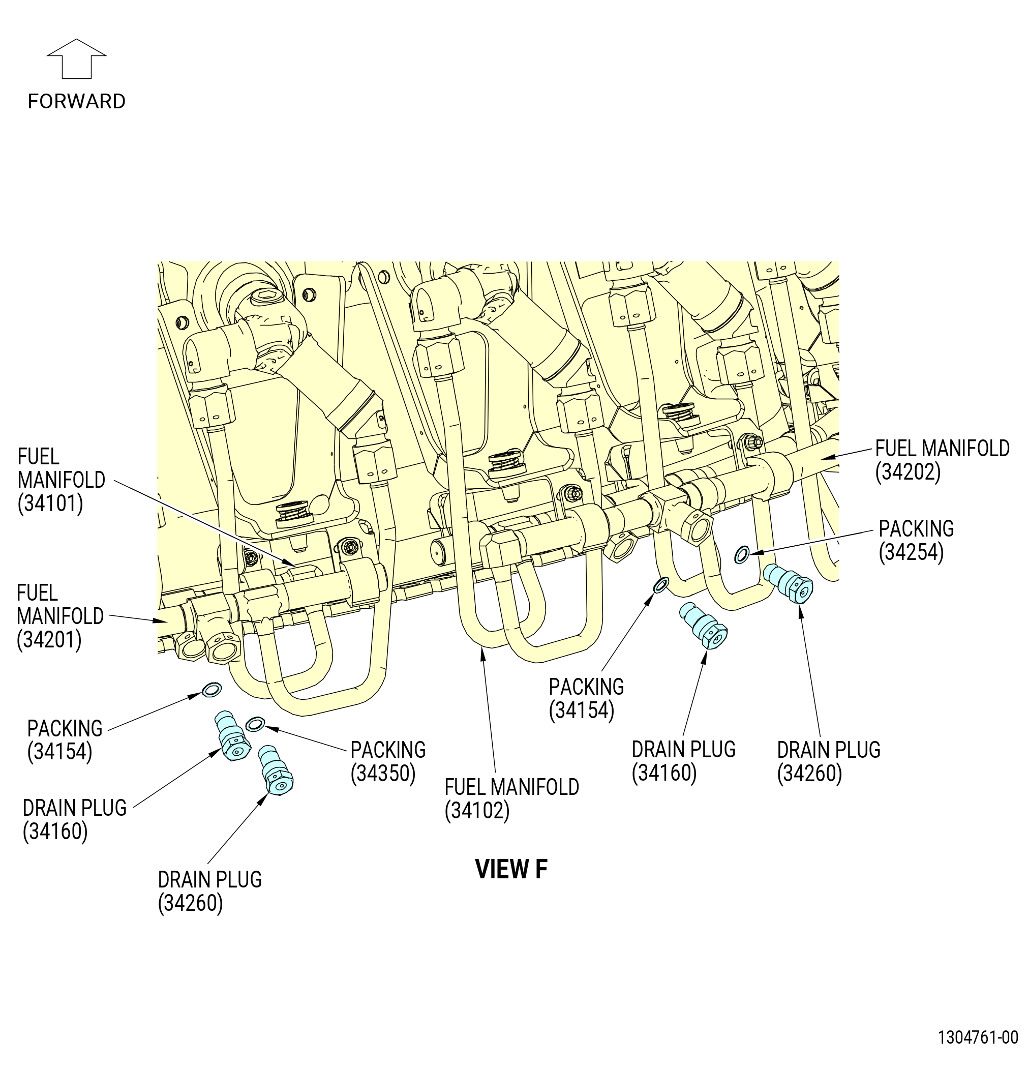
| (21) | Install the fuel manifold drain plugs (drain plugs) (34160) as follows: |
| WARNING: |
|
| (a) | Apply C02-023 engine oil to the preformed packings (10-060 , 73-11-40) (SIN 34154). |
| (b) | Apply C02-023 engine oil to the lead-in chamfers of the fuel manifold and the threads and friction surfaces of the drain plugs. |
| (c) | Install the preformed packings (10-060 , 73-11-40) (SIN 34154) on the drain plugs. |
| (d) | Install the drain plugs on the fuel manifolds (34101) and (34102). |
| (e) | Torque the drain plugs to 262-308 lb in. (29.6-34.8 N.m). |
| (22) | Install the fuel manifold drain plugs (drain plugs) (34260) as follows: |
| WARNING: |
|
| (a) | Apply C02-023 engine oil to the preformed packings (15-200 , 73-11-40) (SIN 34254). |
| (b) | Apply C02-023 engine oil to the lead-in chamfers of the fuel manifold and the threads and friction surfaces of the drain plugs. |
| (c) | Install the preformed packings (15-200 , 73-11-40) (SIN 34254) on the drain plugs. |
| (d) | Install the drain plugs on the fuel manifolds (34201, 34202). |
| (e) | Torque the drain plugs to 262-308 lb in. (29.6-34.8 N.m). |
|
|
|
|
|
|
|
|
|
|
|
|
|
|
| Subtask 72-40-00-440-206 |
| * * * SB 73-0093( Engines with New Pigtail Brackets Configuration ) |
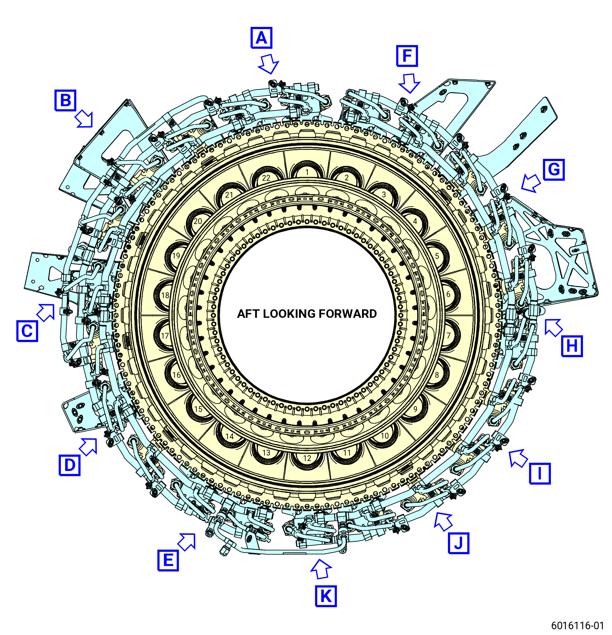
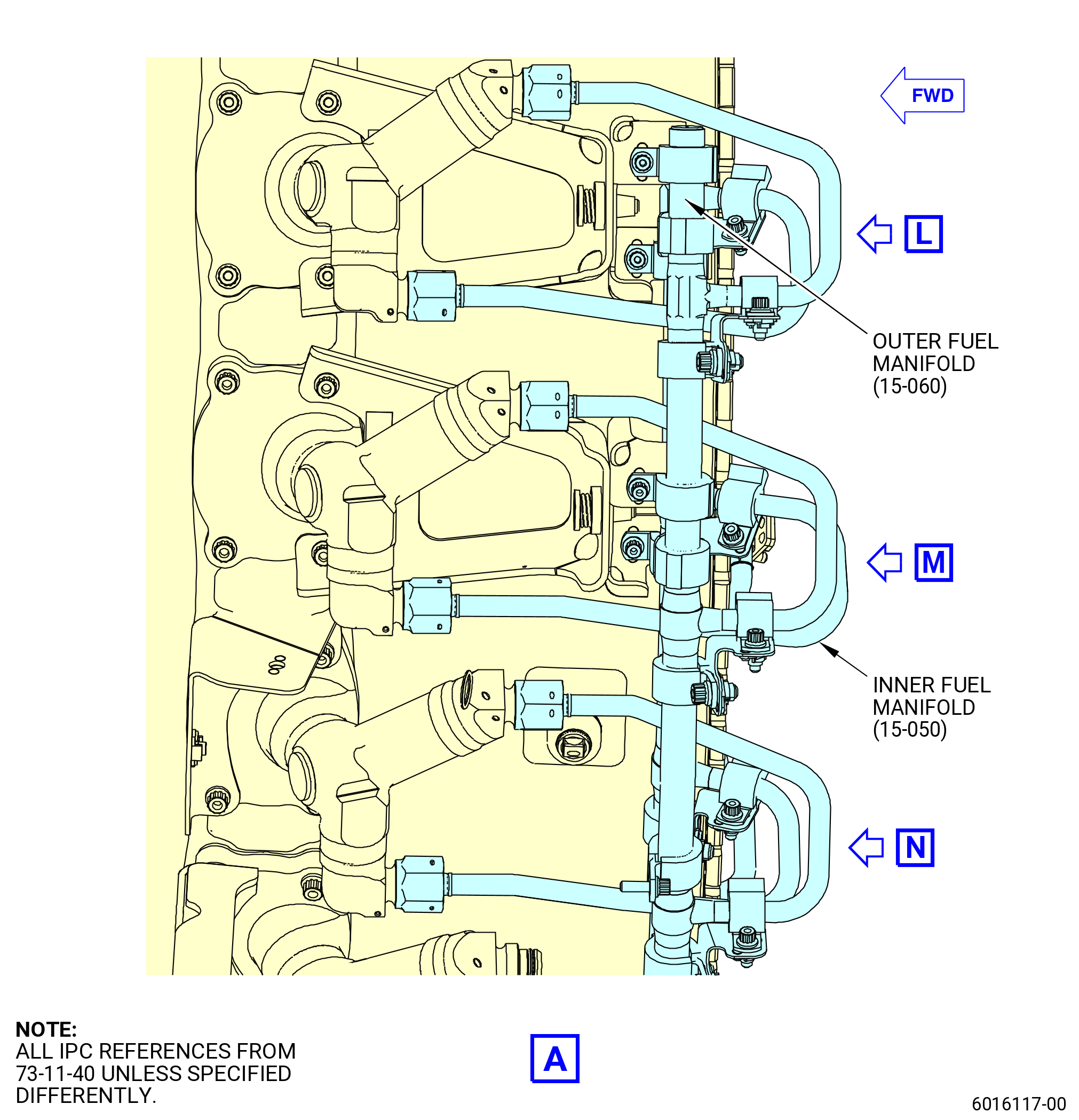
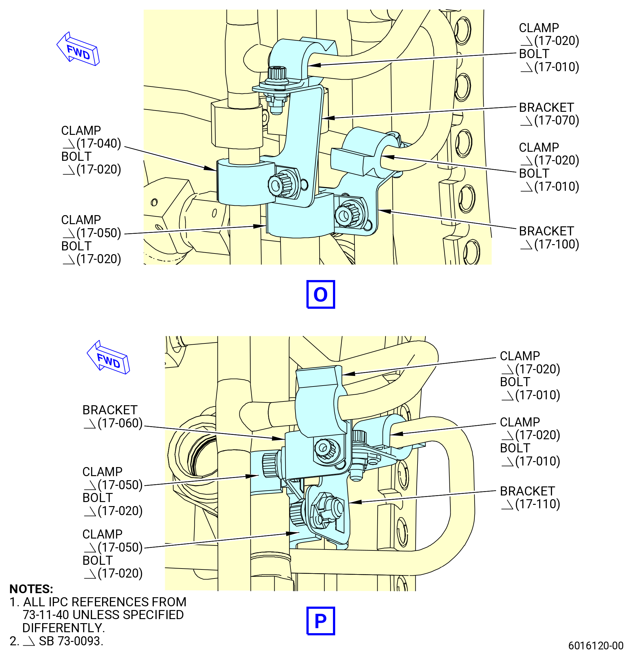
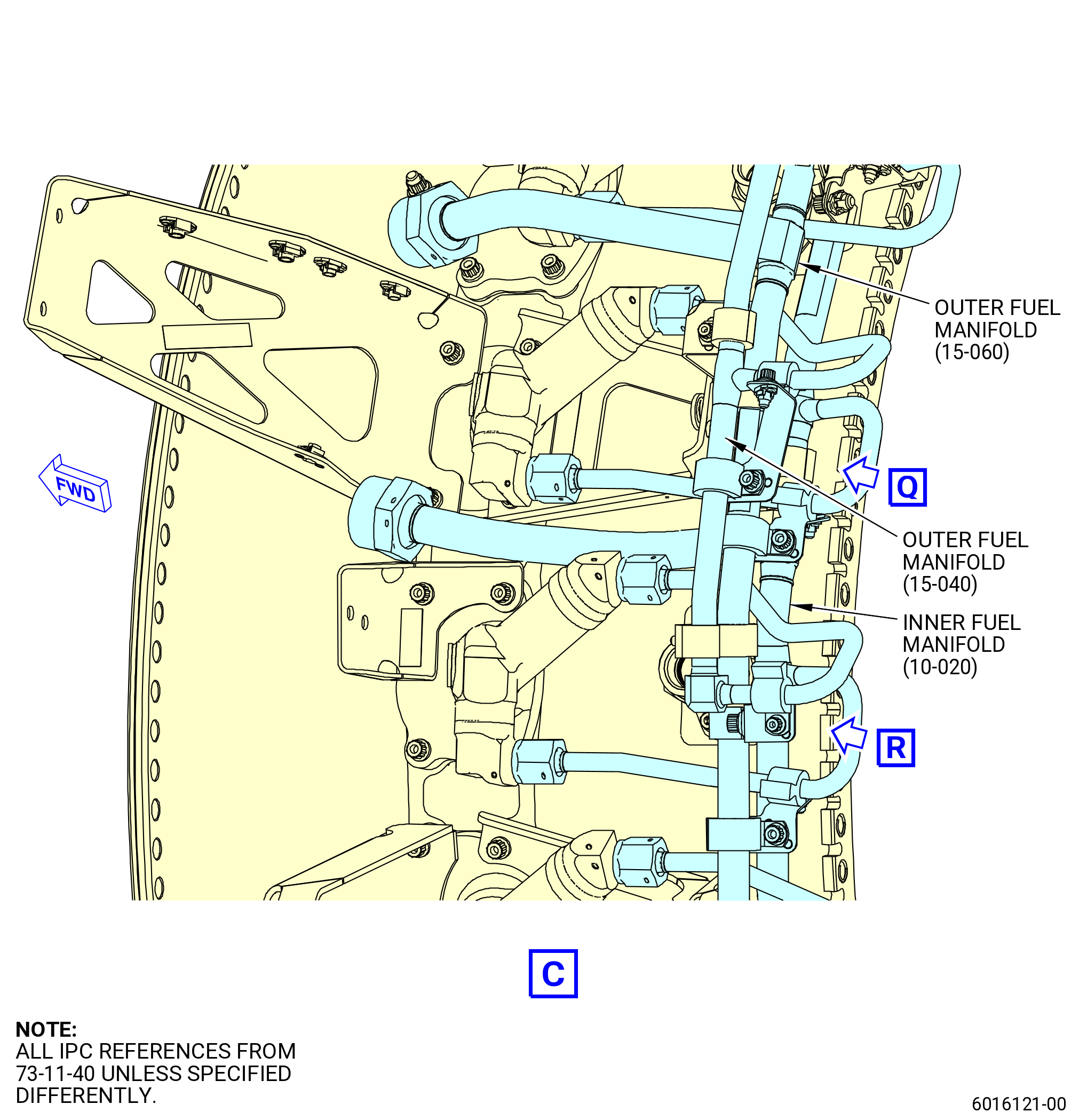
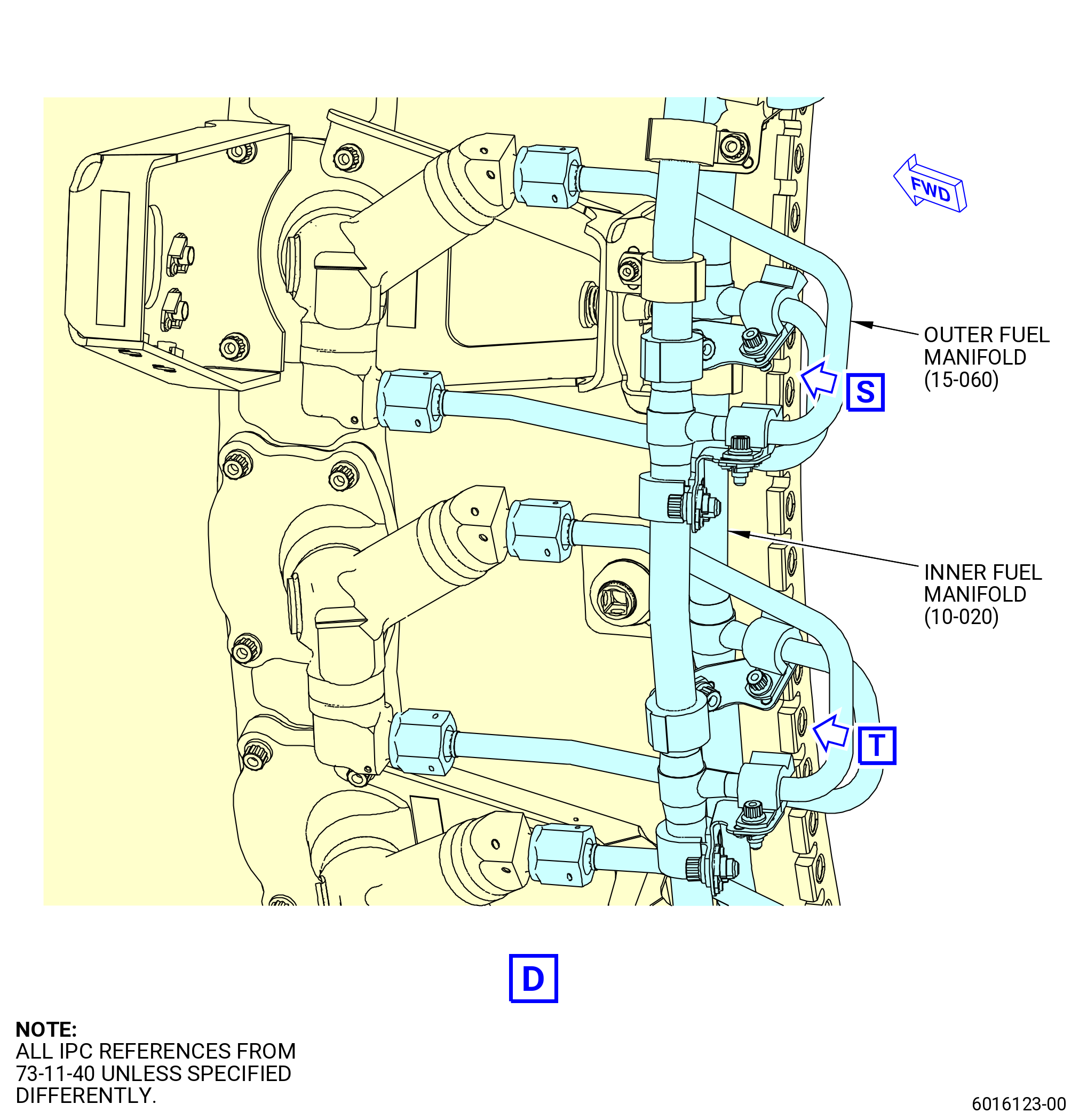
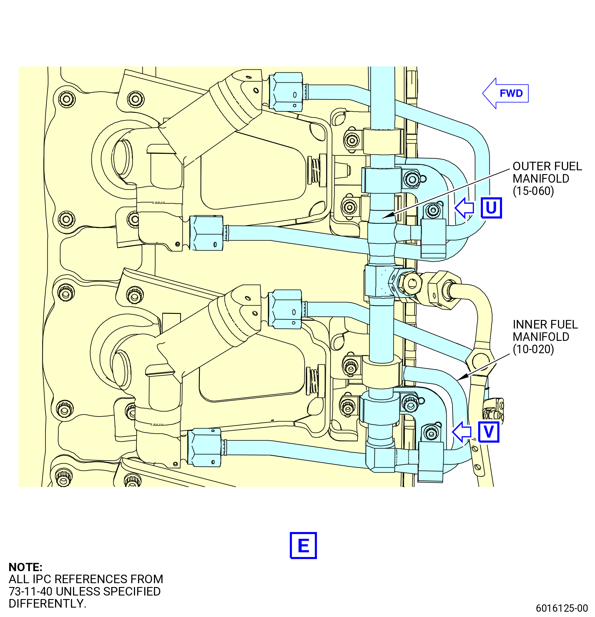
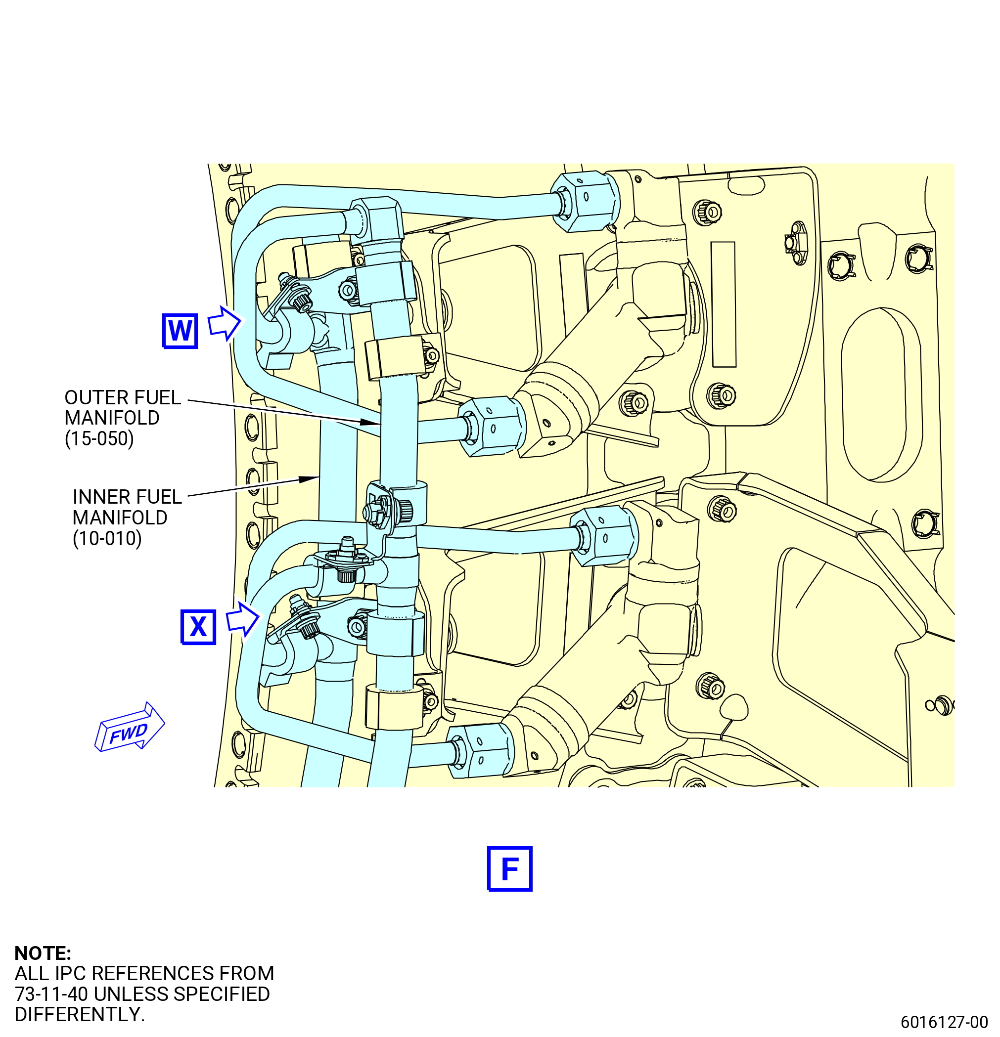
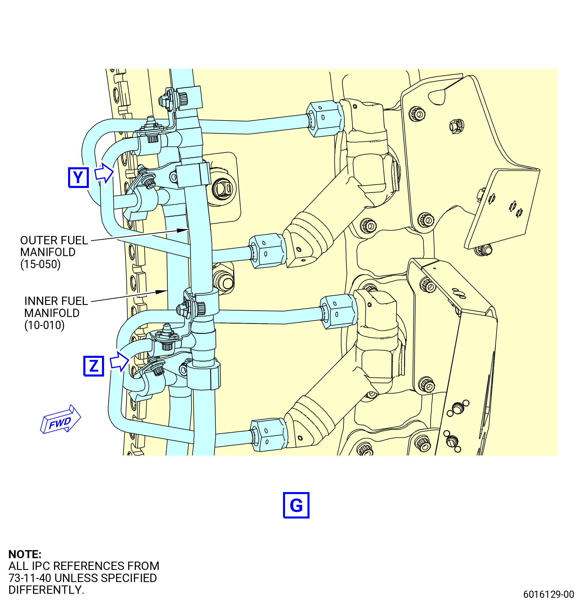
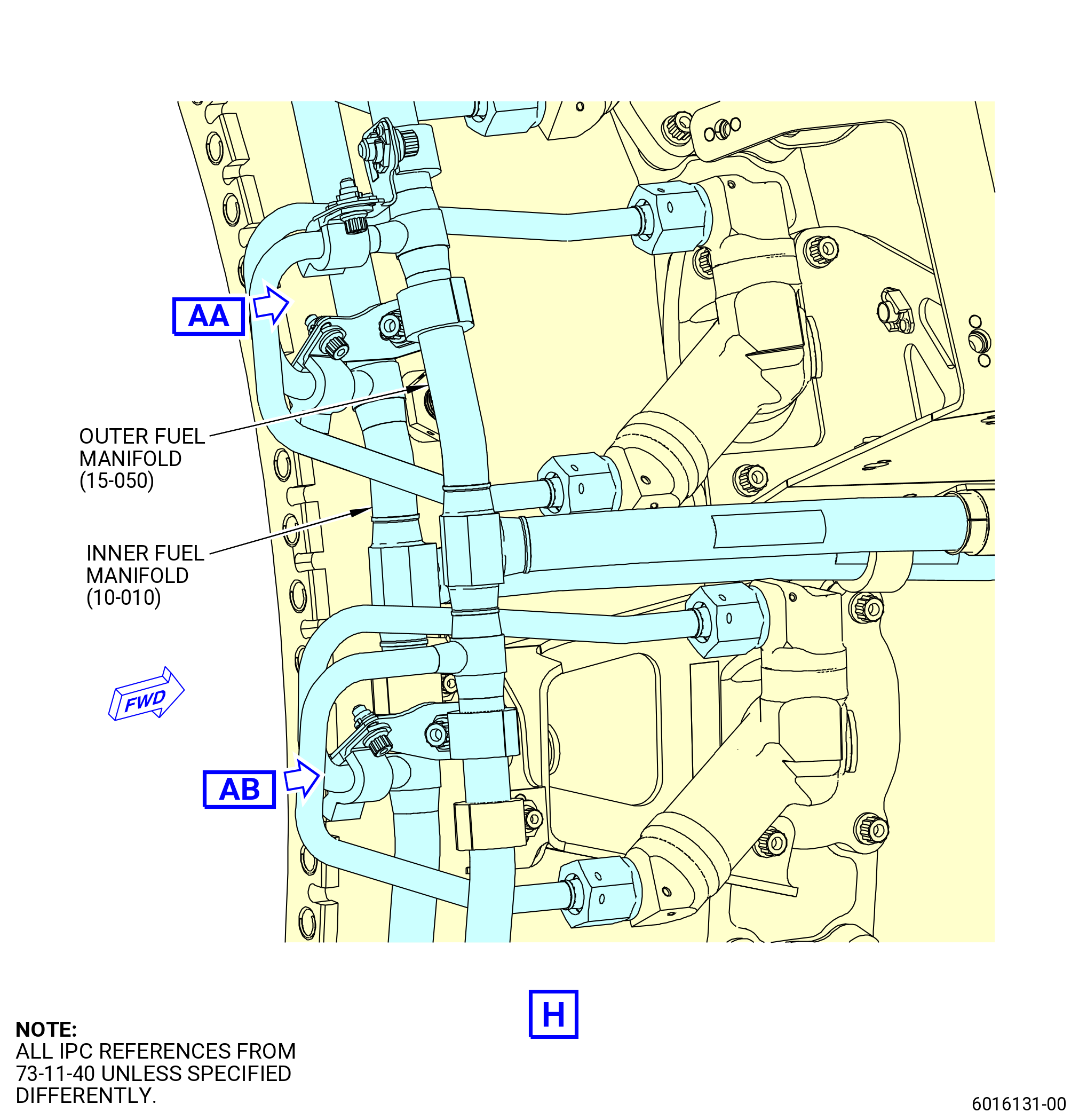
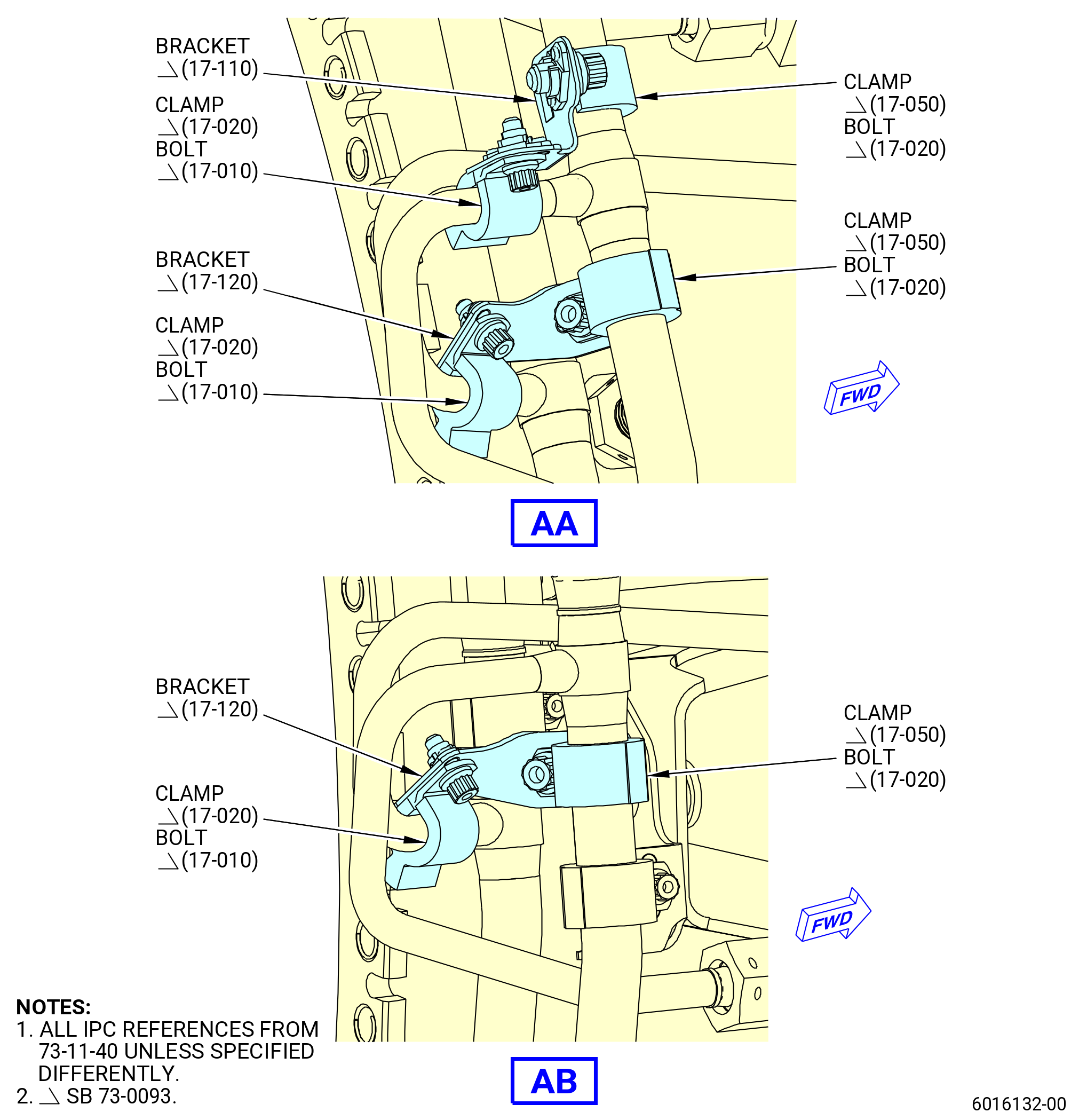
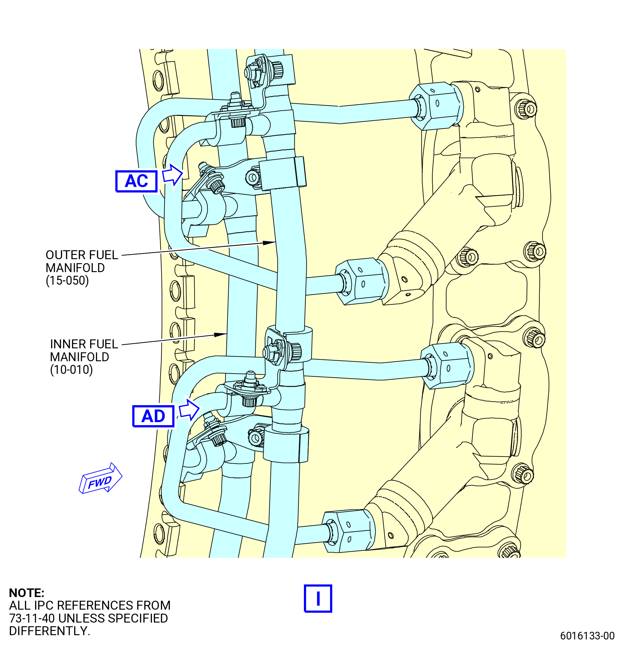
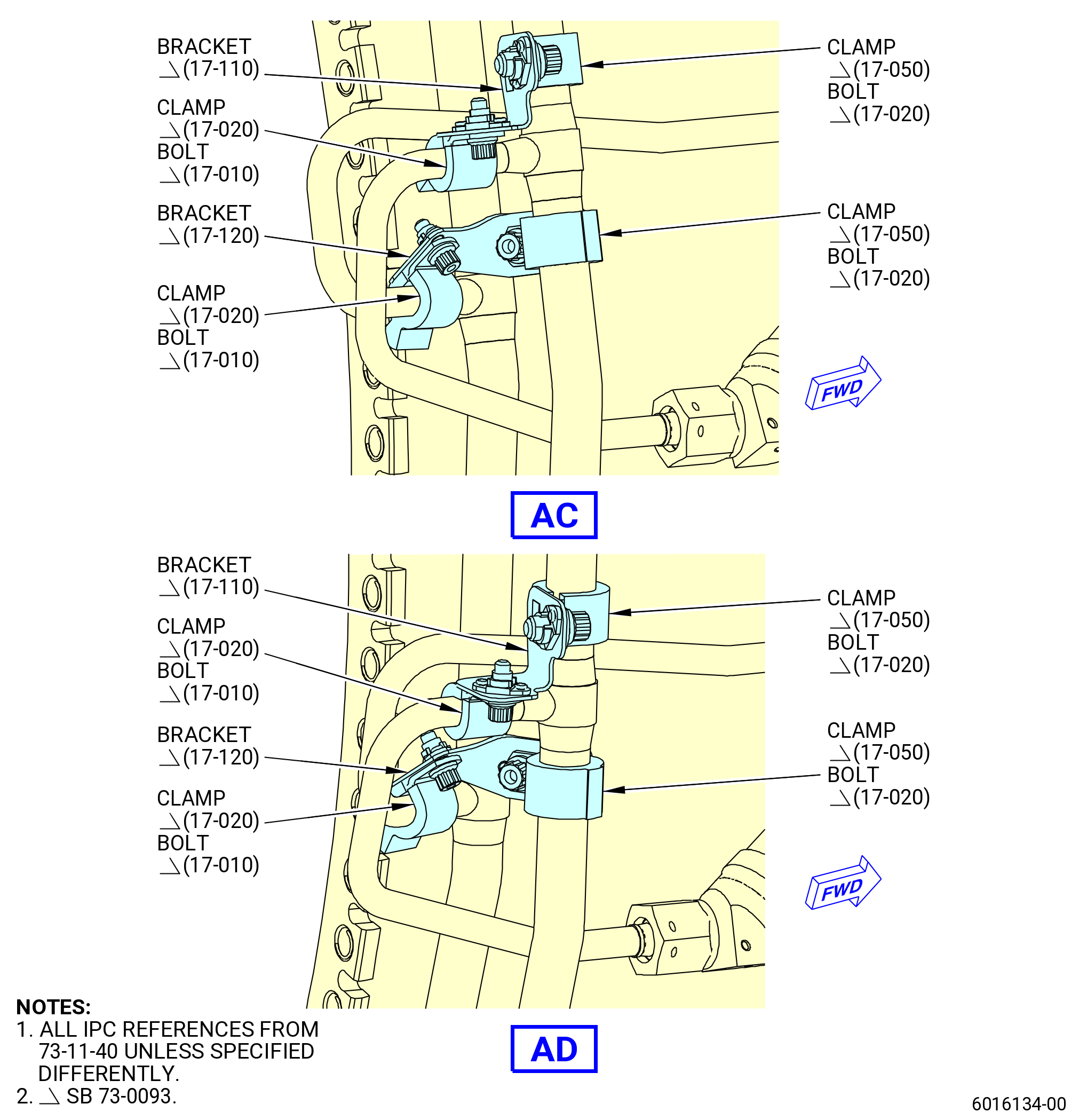
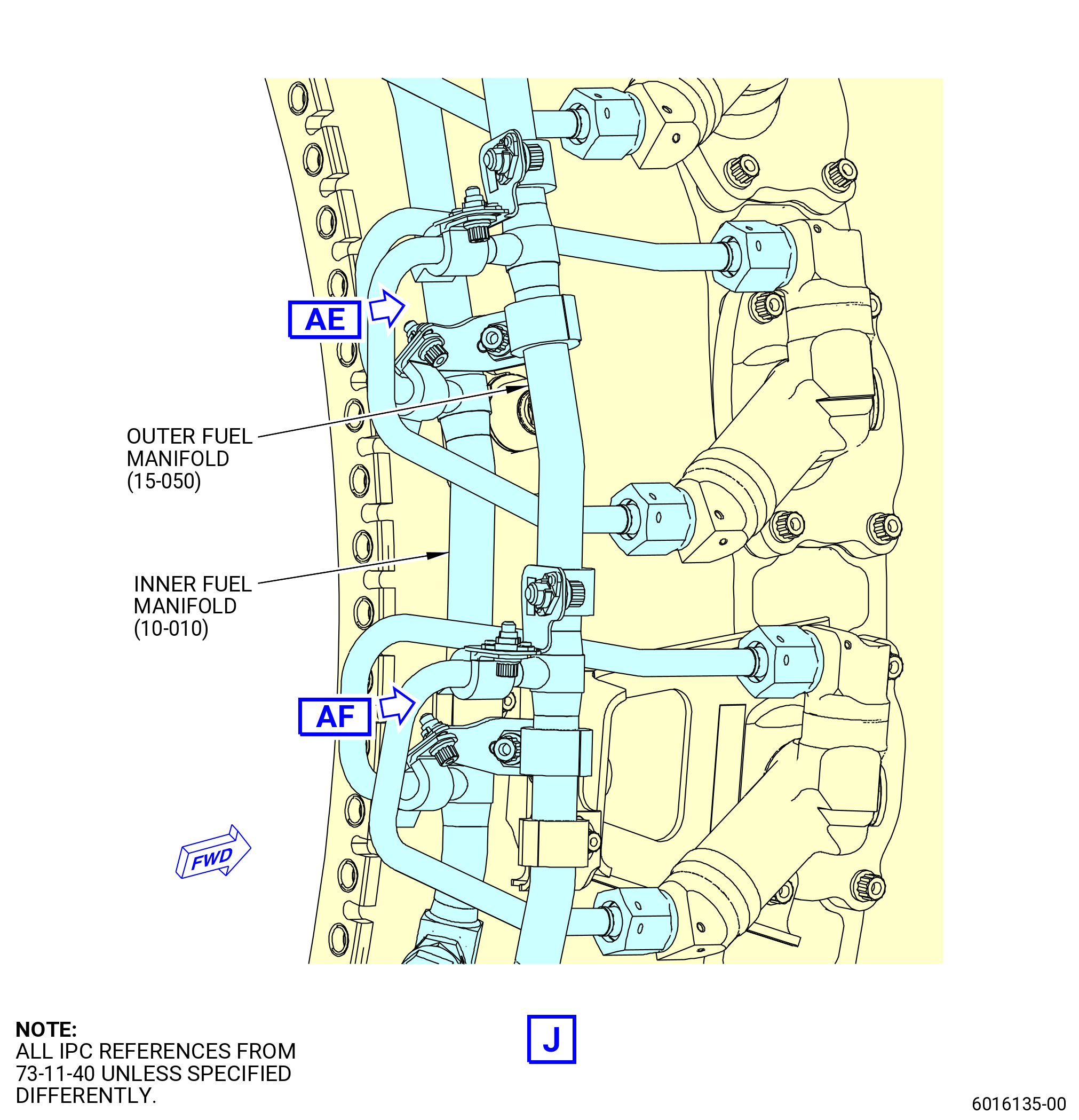
| S. | Install the new support bracket configuration to the outer segment LS fuel manifold (outer fuel manifold) (15-060 , 73-11-40) (SIN 34202), outer signal enriched LS fuel manifold (outer fuel manifold) (15-040 , 73-11-40) (SIN 34302), inner segment LS fuel manifold (inner fuel manifold) (10-020 , 73-11-40) (SIN 34102), outer segment RS fuel manifold (outer fuel manifold) (15-050 , 73-11-40) (SIN 34201) and inner segment RS fuel manifold (inner fuel manifold) (10-010 , 73-11-40) (SIN 34101). Refer to Figure 1025 and as follows: |
| NOTE: |
|
| NOTE: |
|
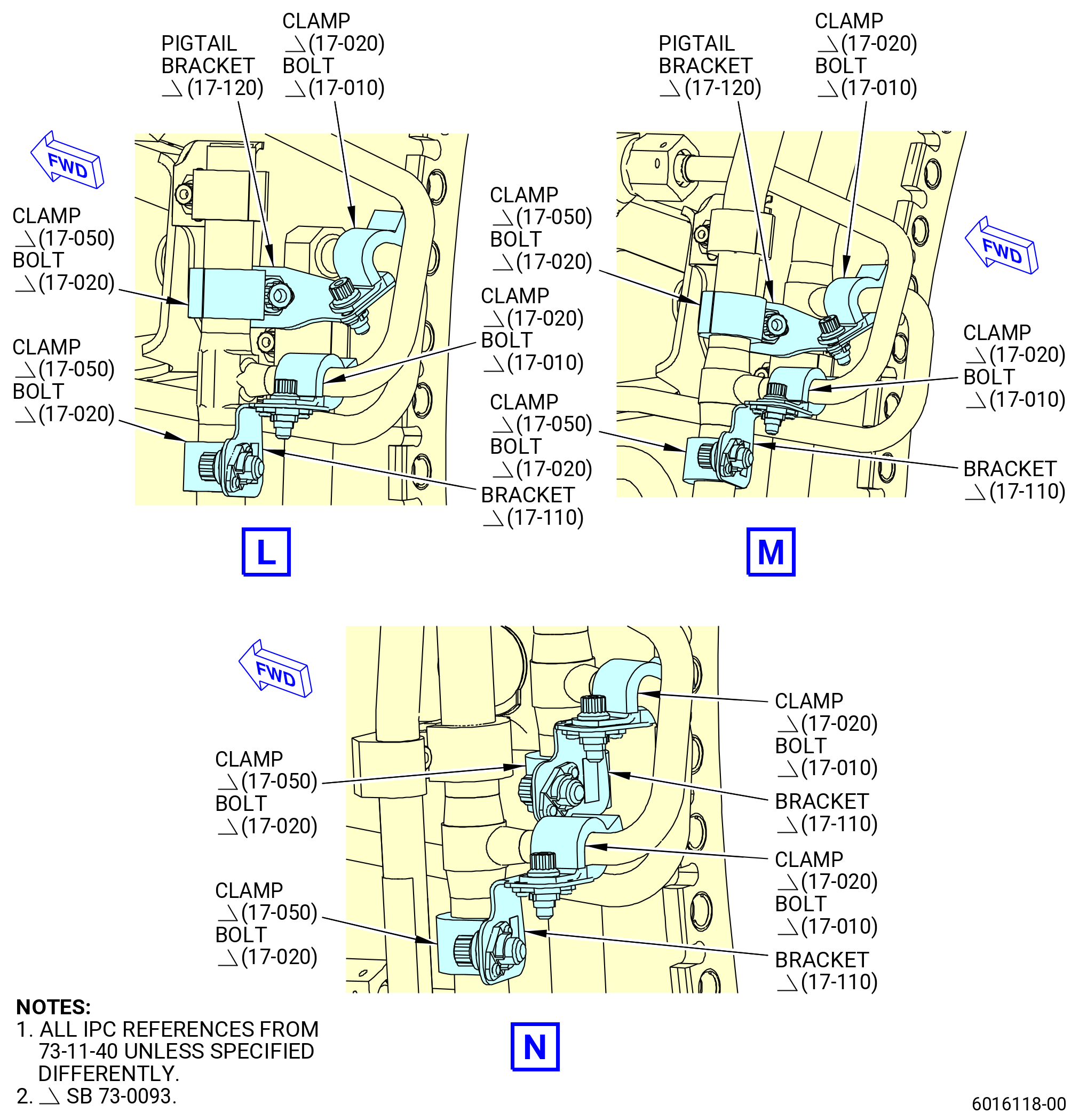
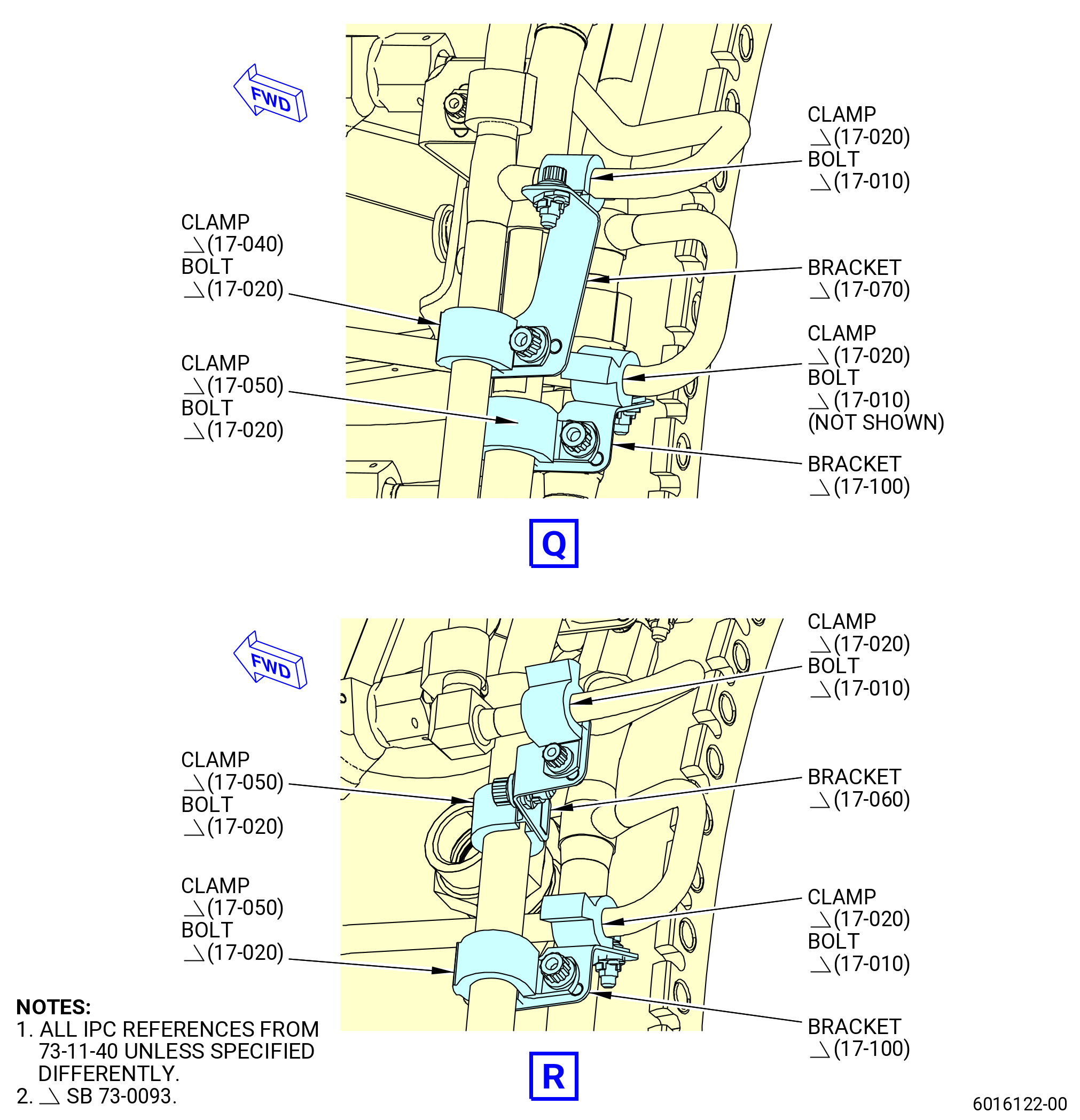
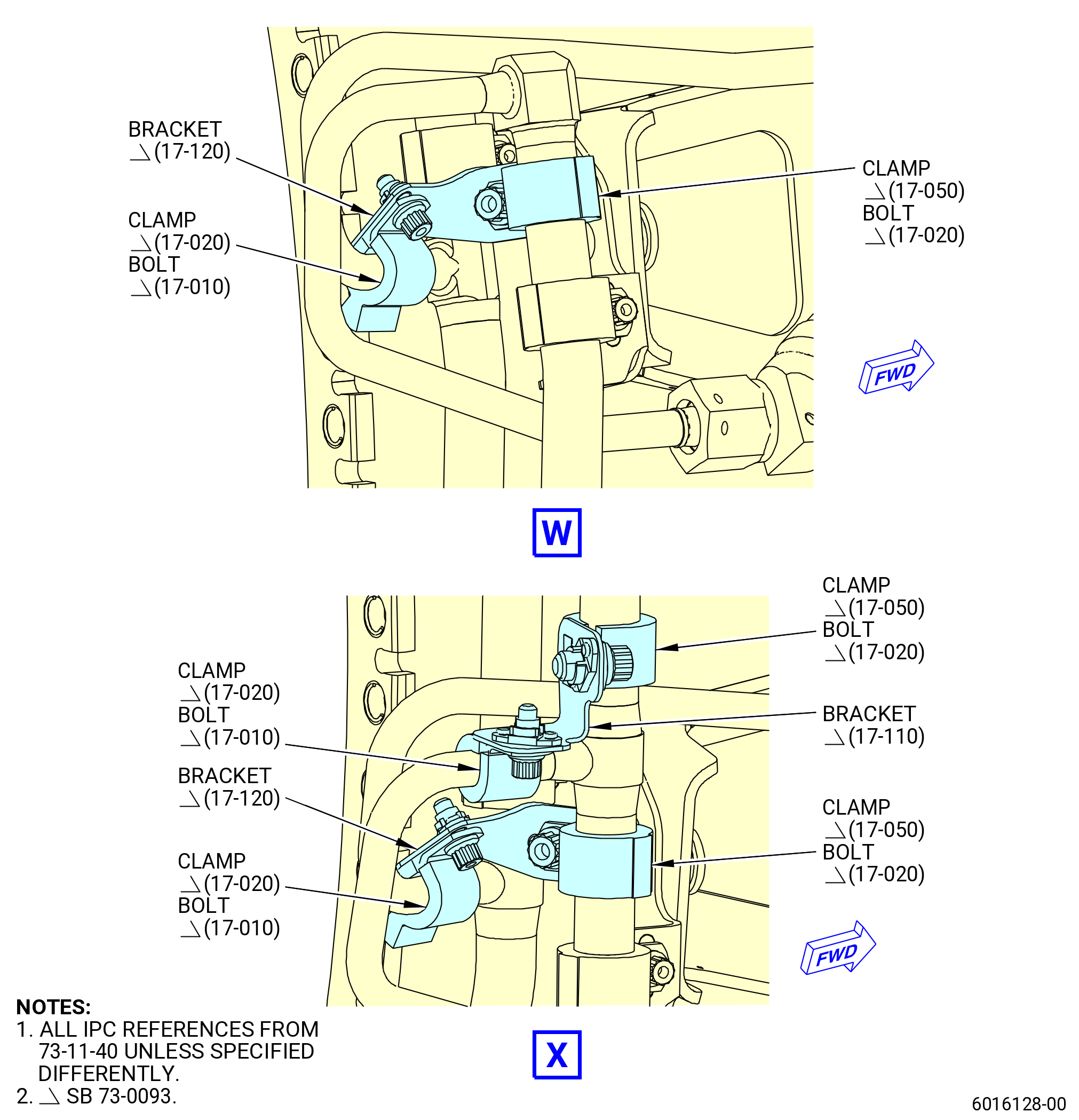
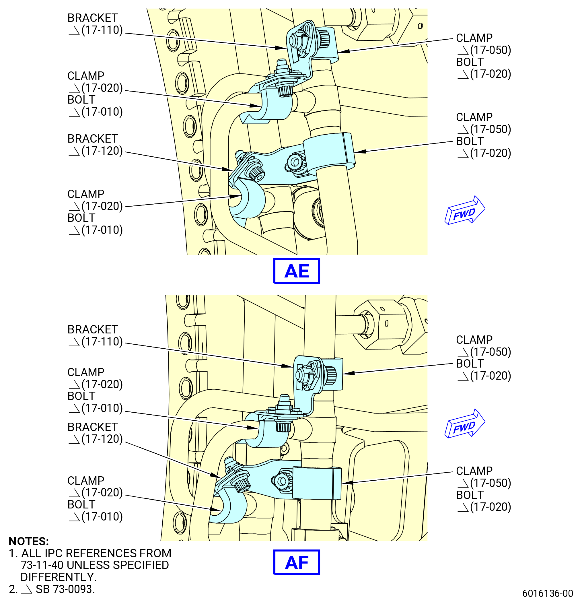
| (1) | Install one pigtail bracket (17-120 , 73-11-40) (SIN 3411V) to attach the outer fuel manifold (15-050 , 73-11-40) (SIN 34201) with a cushioned loop clamp (17-050 , 73-11-40) (SIN 3438C) and a machine bolt (17-020 , 73-11-40) (SIN 3432B) to the pigtail of the inner fuel manifold (10-010 , 73-11-40) (SIN 34101) that connects to the fuel nozzle (05-030 , 73-11-30) (SIN 12500) at position 2 with a cushioned loop clamp (17-020 , 73-11-40) (SIN 3438A) and a machine bolt (17-010 , 73-11-40) (SIN 3432A). Hand-tighten the bolts at this time. |
| (2) | Install one pigtail bracket (17-110 , 73-11-40) (SIN 3411U) to attach the outer fuel manifold (15-050 , 73-11-40) (SIN 34201) with a cushioned loop clamp (17-050 , 73-11-40) (SIN 3438C) and a machine bolt (17-020 , 73-11-40) (SIN 3432B) to the pigtail of the outer fuel manifold (15-050 , 73-11-40) (SIN 34201) that connects to the fuel nozzle (05-040 , 73-11-30) (SIN 12500) at position 3 with a cushioned loop clamp (17-020 , 73-11-40) (SIN 3438A) and a machine bolt (17-010 , 73-11-40) (SIN 3432A). Hand-tighten the bolts at this time. |
| (3) | Install one pigtail bracket (17-120 , 73-11-40) (SIN 3411V) to attach the outer fuel manifold (15-050 , 73-11-40) (SIN 34201) with a cushioned loop clamp (17-050 , 73-11-40) (SIN 3438C) and a machine bolt (17-020 , 73-11-40) (SIN 3432B) to the pigtail of the inner fuel manifold (10-010 , 73-11-40) (SIN 34101) that connects to the fuel nozzle (05-040 , 73-11-30) (SIN 12500) at position 3 with a cushioned loop clamp (17-020 , 73-11-40) (SIN 3438A) and a machine bolt (17-010 , 73-11-40) (SIN 3432A). Hand-tighten the bolts at this time. |
| (4) | Install one pigtail bracket (17-110 , 73-11-40) (SIN 3411U) to attach the outer fuel manifold (15-050 , 73-11-40) (SIN 34201) with a cushioned loop clamp (17-050 , 73-11-40) (SIN 3438C) and a machine bolt (17-020 , 73-11-40) (SIN 3432B) to the pigtail of the outer fuel manifold (15-050 , 73-11-40) (SIN 34201) that connects to the fuel nozzle (05-050 , 73-11-30) (SIN 12500) at position 4 with a cushioned loop clamp (17-020 , 73-11-40) (SIN 3438A) and a machine bolt (17-010 , 73-11-40) (SIN 3432A). Hand-tighten the bolts at this time. |
| (5) | Install one pigtail bracket (17-120 , 73-11-40) (SIN 3411V) to attach the outer fuel manifold (15-050 , 73-11-40) (SIN 34201) with a cushioned loop clamp (17-050 , 73-11-40) (SIN 3438C) and a machine bolt (17-020 , 73-11-40) (SIN 3432B) to the pigtail of the inner fuel manifold (10-010 , 73-11-40) (SIN 34101) that connects to the fuel nozzle (05-050 , 73-11-30) (SIN 12500) at position 4 with a cushioned loop clamp (17-020 , 73-11-40) (SIN 3438A) and a machine bolt (17-010 , 73-11-40) (SIN 3432A). Hand-tighten the bolts at this time. |
| (6) | Install one pigtail bracket (17-110 , 73-11-40) (SIN 3411U) to attach the outer fuel manifold (15-050 , 73-11-40) (SIN 34201) with a cushioned loop clamp (17-050 , 73-11-40) (SIN 3438C) and a machine bolt (17-020 , 73-11-40) (SIN 3432B) to the pigtail of the outer fuel manifold (15-050 , 73-11-40) (SIN 34201) that connects to the fuel nozzle (05-060 , 73-11-30) (SIN 12500) at position 5 with a cushioned loop clamp (17-020 , 73-11-40) (SIN 3438A) and a machine bolt (17-010 , 73-11-40) (SIN 3432A). Hand-tighten the bolts at this time. |
| (7) | Install one pigtail bracket (17-120 , 73-11-40) (SIN 3411V) to attach the outer fuel manifold (15-050 , 73-11-40) (SIN 34201) with a cushioned loop clamp (17-050 , 73-11-40) (SIN 3438C) and a machine bolt (17-020 , 73-11-40) (SIN 3432B) to the pigtail of the inner fuel manifold (10-010 , 73-11-40) (SIN 34101) that connects to the fuel nozzle (05-060 , 73-11-30) (SIN 12500) at position 5 with a cushioned loop clamp (17-020 , 73-11-40) (SIN 3438A) and a machine bolt (17-010 , 73-11-40) (SIN 3432A). Hand-tighten the bolts at this time. |
| (8) | Install one pigtail bracket (17-110 , 73-11-40) (SIN 3411U) to attach the outer fuel manifold (15-050 , 73-11-40) (SIN 34201) with a cushioned loop clamp (17-050 , 73-11-40) (SIN 3438C) and a machine bolt (17-020 , 73-11-40) (SIN 3432B) to the pigtail of the outer fuel manifold (15-050 , 73-11-40) (SIN 34201) that connects to the fuel nozzle (05-070 , 73-11-30) (SIN 12500) at position 6 with a cushioned loop clamp (17-020 , 73-11-40) (SIN 3438A) and a machine bolt (17-010 , 73-11-40) (SIN 3432A). Hand-tighten the bolts at this time. |
| (9) | Install one pigtail bracket (17-120 , 73-11-40) (SIN 3411V) to attach the outer fuel manifold (15-050 , 73-11-40) (SIN 34201) with a cushioned loop clamp (17-050 , 73-11-40) (SIN 3438C) and a machine bolt (17-020 , 73-11-40) (SIN 3432B) to the pigtail of the inner fuel manifold (10-010 , 73-11-40) (SIN 34101) that connects to the fuel nozzle (05-070 , 73-11-30) (SIN 12500) at position 6 with a cushioned loop clamp (17-020 , 73-11-40) (SIN 3438A) and a machine bolt (17-010 , 73-11-40) (SIN 3432A). Hand-tighten the bolts at this time. |
| (10) | Install one pigtail bracket (17-120 , 73-11-40) (SIN 3411V) to attach the outer fuel manifold (15-050 , 73-11-40) (SIN 34201) with a cushioned loop clamp (17-050 , 73-11-40) (SIN 3438C) and a machine bolt (17-020 , 73-11-40) (SIN 3432B) to the pigtail of the inner fuel manifold (10-010 , 73-11-40) (SIN 34101) that connects to the fuel nozzle (05-080 , 73-11-30) (SIN 12500) at position 7 with a cushioned loop clamp (17-020 , 73-11-40) (SIN 3438A) and a machine bolt (17-010 , 73-11-40) (SIN 3432A). Hand-tighten the bolts at this time. |
| (11) | Install one pigtail bracket (17-110 , 73-11-40) (SIN 3411U) to attach the outer fuel manifold (15-050 , 73-11-40) (SIN 34201) with a cushioned loop clamp (17-050 , 73-11-40) (SIN 3438C) and a machine bolt (17-020 , 73-11-40) (SIN 3432B) to the pigtail of the outer fuel manifold (15-050 , 73-11-40) (SIN 34201) that connects to the fuel nozzle (05-090 , 73-11-30) (SIN 12500) at position 8 with a cushioned loop clamp (17-020 , 73-11-40) (SIN 3438A) and a machine bolt (17-010 , 73-11-40) (SIN 3432A). Hand-tighten the bolts at this time. |
| (12) | Install one pigtail bracket (17-120 , 73-11-40) (SIN 3411V) to attach the outer fuel manifold (15-050 , 73-11-40) (SIN 34201) with a cushioned loop clamp (17-050 , 73-11-40) (SIN 3438C) and a machine bolt (17-020 , 73-11-40) (SIN 3432B) to the pigtail of the inner fuel manifold (10-010 , 73-11-40) (SIN 34101) that connects to the fuel nozzle (05-090 , 73-11-30) (SIN 12500) at position 8 with a cushioned loop clamp (17-020 , 73-11-40) (SIN 3438A) and a machine bolt (17-010 , 73-11-40) (SIN 3432A). Hand-tighten the bolts at this time. |
| (13) | Install one pigtail bracket (17-110 , 73-11-40) (SIN 3411U) to attach the outer fuel manifold (15-050 , 73-11-40) (SIN 34201) with a cushioned loop clamp (17-050 , 73-11-40) (SIN 3438C) and a machine bolt (17-020 , 73-11-40) (SIN 3432B) to the pigtail of the outer fuel manifold (15-050 , 73-11-40) (SIN 34201) that connects to the fuel nozzle (05-100 , 73-11-30) (SIN 12500) at position 9 with a cushioned loop clamp (17-020 , 73-11-40) (SIN 3438A) and a machine bolt (17-010 , 73-11-40) (SIN 3432A). Hand-tighten the bolts at this time. |
| (14) | Install one pigtail bracket (17-120 , 73-11-40) (SIN 3411V) to attach the outer fuel manifold (15-050 , 73-11-40) (SIN 34201) with a cushioned loop clamp (17-050 , 73-11-40) (SIN 3438C) and a machine bolt (17-020 , 73-11-40) (SIN 3432B) to the pigtail of the inner fuel manifold (10-010 , 73-11-40) (SIN 34101) that connects to the fuel nozzle (05-100 , 73-11-30) (SIN 12500) at position 9 with a cushioned loop clamp (17-020 , 73-11-40) (SIN 3438A) and a machine bolt (17-010 , 73-11-40) (SIN 3432A). Hand-tighten the bolts at this time. |
| (15) | Install one pigtail bracket (17-110 , 73-11-40) (SIN 3411U) to attach the outer fuel manifold (15-050 , 73-11-40) (SIN 34201) with a cushioned loop clamp (17-050 , 73-11-40) (SIN 3438C) and a machine bolt (17-020 , 73-11-40) (SIN 3432B) to the pigtail of the outer fuel manifold (15-050 , 73-11-40) (SIN 34201) that connects to the fuel nozzle (05-110 , 73-11-30) (SIN 12500) at position 10 with a cushioned loop clamp (17-020 , 73-11-40) (SIN 3438A) and a machine bolt (17-010 , 73-11-40) (SIN 3432A). Hand-tighten the bolts at this time. |
| (16) | Install one pigtail bracket (17-120 , 73-11-40) (SIN 3411V) to attach the outer fuel manifold (15-050 , 73-11-40) (SIN 34201) with a cushioned loop clamp (17-050 , 73-11-40) (SIN 3438C) and a machine bolt (17-020 , 73-11-40) (SIN 3432B) to the pigtail of the inner fuel manifold (10-010 , 73-11-40) (SIN 34101) that connects to the fuel nozzle (05-110 , 73-11-30) (SIN 12500) at position 10 with a cushioned loop clamp (17-020 , 73-11-40) (SIN 3438A) and a machine bolt (17-010 , 73-11-40) (SIN 3432A). Hand-tighten the bolts at this time. |
| (17) | Install one pigtail bracket (17-110 , 73-11-40) (SIN 3411U) to attach the outer fuel manifold (15-050 , 73-11-40) (SIN 34201) with a cushioned loop clamp (17-050 , 73-11-40) (SIN 3438C) and a machine bolt (17-020 , 73-11-40) (SIN 3432B) to the pigtail of the outer fuel manifold (15-050 , 73-11-40) (SIN 34201) that connects to the fuel nozzle (05-120 , 73-11-30) (SIN 12500) at position 11 with a cushioned loop clamp (17-020 , 73-11-40) (SIN 3438A) and a machine bolt (17-010 , 73-11-40) (SIN 3432A). Hand-tighten the bolts at this time. |
| (18) | Install one pigtail bracket (17-120 , 73-11-40) (SIN 3411V) to attach the outer fuel manifold (15-050 , 73-11-40) (SIN 34201) with a cushioned loop clamp (17-050 , 73-11-40) (SIN 3438C) and a machine bolt (17-020 , 73-11-40) (SIN 3432B) to the pigtail of the inner fuel manifold (10-010 , 73-11-40) (SIN 34101) that connects to the fuel nozzle (05-120 , 73-11-30) (SIN 12500) at position 11 with a cushioned loop clamp (17-020 , 73-11-40) (SIN 3438A) and a machine bolt (17-010 , 73-11-40) (SIN 3432A). Hand-tighten the bolts at this time. |
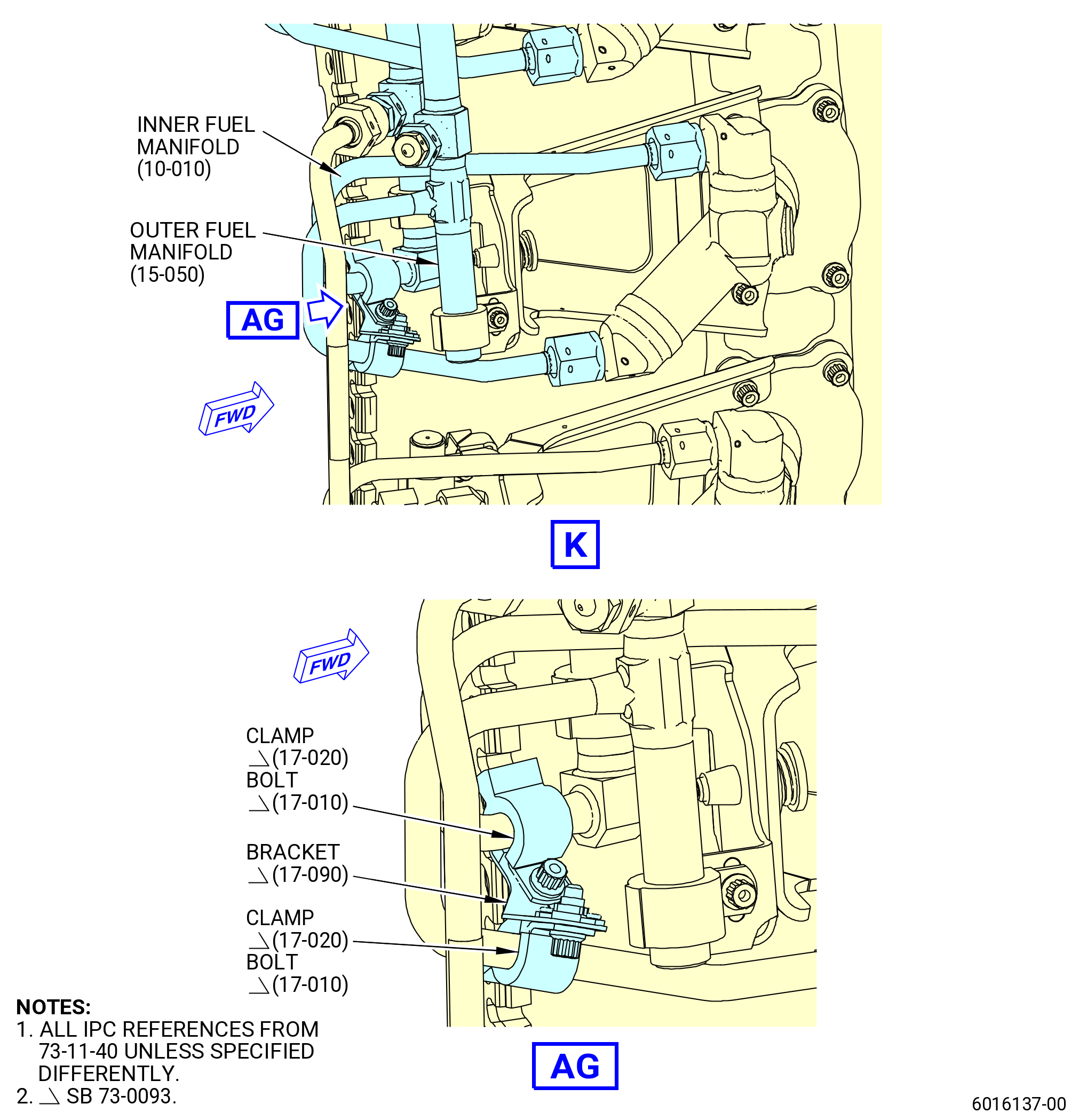
| (19) | Install one pigtail bracket (17-090 , 73-11-40) (SIN 3411Y) to attach the outer fuel manifold (15-050 , 73-11-40) (SIN 34201) with a cushioned loop clamp (17-020 , 73-11-40) (SIN 3438A) and a machine bolt (17-010 , 73-11-40) (SIN 3432A) to the pigtail of the inner fuel manifold (10-010 , 73-11-40) (SIN 34101) that connects to the fuel nozzle (05-130 , 73-11-30) (SIN 12500) at position 12 with a cushioned loop clamp (17-020 , 73-11-40) (SIN 3438A) and a machine bolt (17-010 , 73-11-40) (SIN 3432A). Hand-tighten the bolts at this time. |
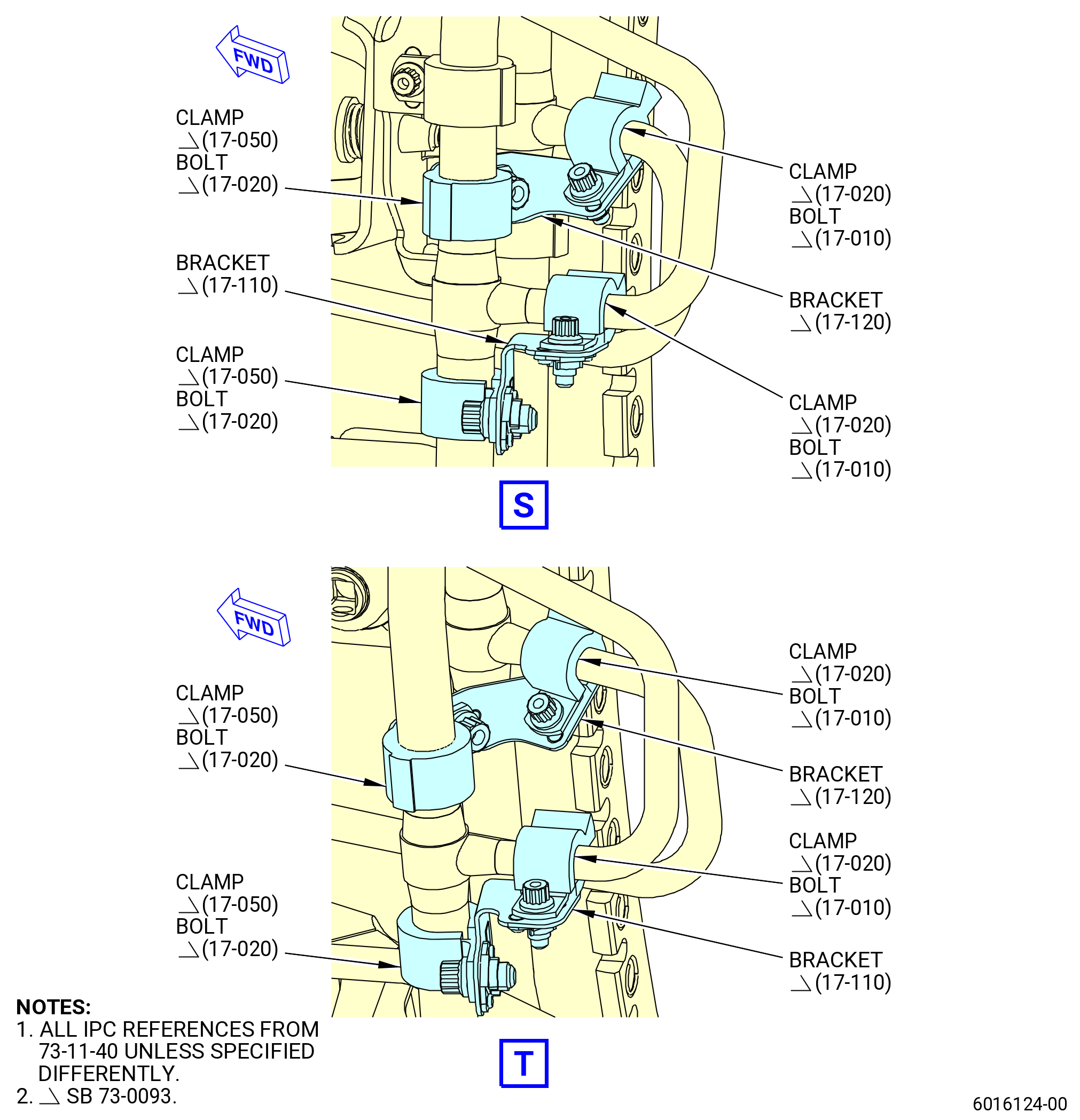
| (20) | Install one pigtail bracket (17-080 , 73-11-40) (SIN 3431J) to attach the outer fuel manifold (15-060 , 73-11-40) (SIN 34202) with a cushioned loop clamp (17-050 , 73-11-40) (SIN 3438C) and a machine bolt (17-020 , 73-11-40) (SIN 3432B) to the pigtail of the outer fuel manifold (15-060 , 73-11-40) (SIN 34202) that connects to the fuel nozzle (05-140 , 73-11-30) (SIN 12500) at position 13 with a cushioned loop clamp (17-020 , 73-11-40) (SIN 3438A) and a machine bolt (17-010 , 73-11-40) (SIN 3432A). Hand-tighten the bolts at this time. |
| (21) | Install one pigtail bracket (17-080 , 73-11-40) (SIN 3431J) to attach the outer fuel manifold (15-060 , 73-11-40) (SIN 34202) with a cushioned loop clamp (17-050 , 73-11-40) (SIN 3438C) and a machine bolt (17-020 , 73-11-40) (SIN 3432B) to the pigtail of the outer fuel manifold (15-060 , 73-11-40) (SIN 34202) that connects to the fuel nozzle (05-150 , 73-11-30) (SIN 12500) at position 14 with a cushioned loop clamp (17-020 , 73-11-40) (SIN 3438A) and a machine bolt (17-010 , 73-11-40) (SIN 3432A). Hand-tighten the bolts at this time. |
| (22) | Install one pigtail bracket (17-110 , 73-11-40) (SIN 3411U) to attach the outer fuel manifold (15-060 , 73-11-40) (SIN 34202) with a cushioned loop clamp (17-050 , 73-11-40) (SIN 3438C) and a machine bolt (17-020 , 73-11-40) (SIN 3432B) to the pigtail of the outer fuel manifold (15-060 , 73-11-40) (SIN 34202) that connects to the fuel nozzle (05-160 , 73-11-30) (SIN 12500) at position 15 with a cushioned loop clamp (17-020 , 73-11-40) (SIN 3438A) and a machine bolt (17-010 , 73-11-40) (SIN 3432A). Hand-tighten the bolts at this time. |
| (23) | Install one pigtail bracket (17-120 , 73-11-40) (SIN 3411V) to attach the outer fuel manifold (15-060 , 73-11-40) (SIN 34202) with a cushioned loop clamp (17-050 , 73-11-40) (SIN 3438C) and a machine bolt (17-020 , 73-11-40) (SIN 3432B) to the pigtail of the inner fuel manifold (10-020 , 73-11-40) (SIN 34102) that connects to the fuel nozzle (05-160 , 73-11-30) (SIN 12500) at position 15 with a cushioned loop clamp (17-020 , 73-11-40) (SIN 3438A) and a machine bolt (17-010 , 73-11-40) (SIN 3432A). Hand-tighten the bolts at this time. |
| (24) | Install one pigtail bracket (17-110 , 73-11-40) (SIN 3411U) to attach the outer fuel manifold (15-060 , 73-11-40) (SIN 34202) with a cushioned loop clamp (17-050 , 73-11-40) (SIN 3438C) and a machine bolt (17-020 , 73-11-40) (SIN 3432B) to the pigtail of the outer fuel manifold (15-060 , 73-11-40) (SIN 34202) that connects to the fuel nozzle (05-170 , 73-11-30) (SIN 12500) at position 16 with a cushioned loop clamp (17-020 , 73-11-40) (SIN 3438A) and a machine bolt (17-010 , 73-11-40) (SIN 3432A). Hand-tighten the bolts at this time. |
| (25) | Install one pigtail bracket (17-120 , 73-11-40) (SIN 3411V) to attach the outer fuel manifold (15-060 , 73-11-40) (SIN 34202) with a cushioned loop clamp (17-050 , 73-11-40) (SIN 3438C) and a machine bolt (17-020 , 73-11-40) (SIN 3432B) to the pigtail of the inner fuel manifold (10-020 , 73-11-40) (SIN 34102) that connects to the fuel nozzle (05-170 , 73-11-30) (SIN 12500) at position 16 with a cushioned loop clamp (17-020 , 73-11-40) (SIN 3438A) and a machine bolt (17-010 , 73-11-40) (SIN 3432A). Hand-tighten the bolts at this time. |
| (26) | Install one pigtail bracket (17-100 , 73-11-40) (SIN 3411W) to attach the outer fuel manifold (15-060 , 73-11-40) (SIN 34202) with a cushioned loop clamp (17-050 , 73-11-40) (SIN 3438C) and a machine bolt (17-020 , 73-11-40) (SIN 3432B) to the pigtail of the inner fuel manifold (10-020 , 73-11-40) (SIN 34102) that connects to the fuel nozzle (05-180 , 73-11-30) (SIN 12500) at position 17 with a cushioned loop clamp (17-020 , 73-11-40) (SIN 3438A) and a machine bolt (17-010 , 73-11-40) (SIN 3432A). Hand-tighten the bolts at this time. |
| (27) | Install one pigtail bracket (17-060 , 73-11-40) (SIN 3431K) to attach the outer fuel manifold (15-060 , 73-11-40) (SIN 34202) with a cushioned loop clamp (17-050 , 73-11-40) (SIN 3438C) and a machine bolt (17-020 , 73-11-40) (SIN 3432B) to the pigtail of the outer fuel manifold (15-040 , 73-11-40) (SIN 34302) that connects to the fuel nozzle (05-180 , 73-11-30) (SIN 12500) at position 17 with a cushioned loop clamp (17-020 , 73-11-40) (SIN 3438A) and a machine bolt (17-010 , 73-11-40) (SIN 3432A). Hand-tighten the bolts at this time. |
| (28) | Install one pigtail bracket (17-100 , 73-11-40) (SIN 3411W) to attach the outer fuel manifold (15-060 , 73-11-40) (SIN 34202) with a cushioned loop clamp (17-050 , 73-11-40) (SIN 3438C) and a machine bolt (17-020 , 73-11-40) (SIN 3432B) to the pigtail of the inner fuel manifold (10-020 , 73-11-40) (SIN 34102) that connects to the fuel nozzle (05-190 , 73-11-30) (SIN 12500) at position 18 with a cushioned loop clamp (17-020 , 73-11-40) (SIN 3438A) and a machine bolt (17-010 , 73-11-40) (SIN 3432A). Hand-tighten the bolts at this time. |
| (29) | Install one pigtail bracket (17-070 , 73-11-40) (SIN 3431L) to attach the outer fuel manifold (15-040 , 73-11-40) (SIN 34302) with a cushioned loop clamp (17-040 , 73-11-40) (SIN 3438B) and a machine bolt (17-020 , 73-11-40) (SIN 3432B) to the pigtail of the outer fuel manifold (15-040 , 73-11-40) (SIN 34302) that connects to the fuel nozzle (05-190 , 73-11-30) (SIN 12500) at position 18 with a cushioned loop clamp (17-020 , 73-11-40) (SIN 3438A) and a machine bolt (17-010 , 73-11-40) (SIN 3432A). Hand-tighten the bolts at this time. |
| (30) | Install one pigtail bracket (17-060 , 73-11-40) (SIN 3431K) to attach the outer fuel manifold (15-060 , 73-11-40) (SIN 34202) with a cushioned loop clamp (17-050 , 73-11-40) (SIN 3438C) and a machine bolt (17-020 , 73-11-40) (SIN 3432B) to the pigtail of the outer fuel manifold (15-040 , 73-11-40) (SIN 34302) that connects to the fuel nozzle (05-200 , 73-11-30) (SIN 12501) at position 19 with a cushioned loop clamp (17-020 , 73-11-40) (SIN 3438A) and a machine bolt (17-010 , 73-11-40) (SIN 3432A). Hand-tighten the bolts at this time. |
| (31) | Install one pigtail bracket (17-110 , 73-11-40) (SIN 3411U) to attach the inner fuel manifold (10-020 , 73-11-40) (SIN 34102) with a cushioned loop clamp (17-050 , 73-11-40) (SIN 3438C) and a machine bolt (17-020 , 73-11-40) (SIN 3432B) to the pigtail of the inner fuel manifold (10-020 , 73-11-40) (SIN 34102) that connects to the fuel nozzle (05-200 , 73-11-30) (SIN 12501) at position 19 with a cushioned loop clamp (17-020 , 73-11-40) (SIN 3438A) and a machine bolt (17-010 , 73-11-40) (SIN 3432A). Hand-tighten the bolts at this time. |
| (32) | Install one pigtail bracket (17-070 , 73-11-40) (SIN 3431L) to attach the outer fuel manifold (15-040 , 73-11-40) (SIN 34302) with a cushioned loop clamp (17-040 , 73-11-40) (SIN 3438B) and a machine bolt (17-020 , 73-11-40) (SIN 3432B) to the pigtail of the outer fuel manifold (15-040 , 73-11-40) (SIN 34302) that connects to the fuel nozzle (05-210 , 73-11-30) (SIN 12501) at position 20 with a cushioned loop clamp (17-020 , 73-11-40) (SIN 3438A) and a machine bolt (17-010 , 73-11-40) (SIN 3432A). Hand-tighten the bolts at this time. |
| (33) | Install one pigtail bracket (17-100 , 73-11-40) (SIN 3411W) to attach the outer fuel manifold (15-060 , 73-11-40) (SIN 34202) with a cushioned loop clamp (17-050 , 73-11-40) (SIN 3438C) and a machine bolt (17-020 , 73-11-40) (SIN 3432B) to the pigtail of the inner fuel manifold (10-020 , 73-11-40) (SIN 34102) that connects to the fuel nozzle (05-210 , 73-11-30) (SIN 12501) at position 20 with a cushioned loop clamp (17-020 , 73-11-40) (SIN 3438A) and a machine bolt (17-010 , 73-11-40) (SIN 3432A). Hand-tighten the bolts at this time. |
| (34) | Install one pigtail bracket (17-110 , 73-11-40) (SIN 3411U) to attach the outer fuel manifold (15-060 , 73-11-40) (SIN 34202) with a cushioned loop clamp (17-050 , 73-11-40) (SIN 3438C) and a machine bolt (17-020 , 73-11-40) (SIN 3432B) to the pigtail of the outer fuel manifold (15-060 , 73-11-40) (SIN 34202) that connects to the fuel nozzle (05-220 , 73-11-30) (SIN 12501) at position 21 with a cushioned loop clamp (17-020 , 73-11-40) (SIN 3438A) and a machine bolt (17-010 , 73-11-40) (SIN 3432A). Hand-tighten the bolts at this time. |
| (35) | Install one pigtail bracket (17-110 , 73-11-40) (SIN 3411U) to attach the inner fuel manifold (10-020 , 73-11-40) (SIN 34102) with a cushioned loop clamp (17-050 , 73-11-40) (SIN 3438C) and a machine bolt (17-020 , 73-11-40) (SIN 3432B) to the pigtail of the inner fuel manifold (10-020 , 73-11-40) (SIN 34102) that connects to the fuel nozzle (05-220 , 73-11-30) (SIN 12501) at position 21 with a cushioned loop clamp (17-020 , 73-11-40) (SIN 3438A) and a machine bolt (17-010 , 73-11-40) (SIN 3432A). Hand-tighten the bolts at this time. |
| (36) | Install one pigtail bracket (17-110 , 73-11-40) (SIN 3411U) to attach the outer fuel manifold (15-060 , 73-11-40) (SIN 34202) with a cushioned loop clamp (17-050 , 73-11-40) (SIN 3438C) and a machine bolt (17-020 , 73-11-40) (SIN 3432B) to the pigtail of the outer fuel manifold (15-060 , 73-11-40) (SIN 34202) that connects to the fuel nozzle (05-230 , 73-11-30) (SIN 12501) at position 22 with a cushioned loop clamp (17-020 , 73-11-40) (SIN 3438A) and a machine bolt (17-010 , 73-11-40) (SIN 3432A). Hand-tighten the bolts at this time. |
| (37) | Install one pigtail bracket (17-120 , 73-11-40) (SIN 3411V) to attach the outer fuel manifold (15-060 , 73-11-40) (SIN 34202) with a cushioned loop clamp (17-050 , 73-11-40) (SIN 3438C) and a machine bolt (17-020 , 73-11-40) (SIN 3432B) to the pigtail of the inner fuel manifold (10-020 , 73-11-40) (SIN 34102) that connects to the fuel nozzle (05-230 , 73-11-30) (SIN 12501) at position 22 with a cushioned loop clamp (17-020 , 73-11-40) (SIN 3438A) and a machine bolt (17-010 , 73-11-40) (SIN 3432A). Hand-tighten the bolts at this time. |
| (38) | Install one pigtail bracket (17-110 , 73-11-40) (SIN 3411U) to attach the outer fuel manifold (15-060 , 73-11-40) (SIN 34202) with a cushioned loop clamp (17-050 , 73-11-40) (SIN 3438C) and a machine bolt (17-020 , 73-11-40) (SIN 3432B) to the pigtail of the outer fuel manifold (15-060 , 73-11-40) (SIN 34202) that connects to the fuel nozzle (05-240 , 73-11-30) (SIN 12501) at position 1 with a cushioned loop clamp (17-020 , 73-11-40) (SIN 3438A) and a machine bolt (17-010 , 73-11-40) (SIN 3432A). Hand-tighten the bolts at this time. |
| (39) | Install one pigtail bracket (17-120 , 73-11-40) (SIN 3411V) to attach the outer fuel manifold (15-060 , 73-11-40) (SIN 34202) with a cushioned loop clamp (17-050 , 73-11-40) (SIN 3438C) and a machine bolt (17-020 , 73-11-40) (SIN 3432B) to the pigtail of the inner fuel manifold (10-020 , 73-11-40) (SIN 34102) that connects to the fuel nozzle (05-240 , 73-11-30) (SIN 12501) at position 1 with a cushioned loop clamp (17-020 , 73-11-40) (SIN 3438A) and a machine bolt (17-010 , 73-11-40) (SIN 3432A). Hand-tighten the bolts at this time. |
| (40) | Torque the bolts (17-020 , 73-11-40) (SIN 3432B) and (17-010 , 73-11-40) (SIN 3432A) to 51 to 59 lb in. (5.7 to 6.6 Nm). |
| (41) | If one or more clamps (17-020 , 73-11-40) (SIN 3438A), (17-040 , 73-11-40) (SIN 3438B) or (17-050 , 73-11-40) (SIN 3438C) are loose after the final torque procedure, do as follows: |
| (a) | Remove the loose clamps and related bolts (17-010 , 73-11-40) (SIN 3432A) or (17-030 , 73-11-40) (SIN 3432B). |
| WARNING: |
|
| (b) | Clean the outer fuel manifold or inner fuel manifold where the clamps were attached with C04-035 isopropyl alcohol or equivalent and let it dry. |
| NOTE: |
|
| (c) | Put a continuous piece of C10-225 PTFE coated tape or C10-230 PTFE tape around the outer fuel manifold or inner fuel manifold. Apply enough layers of tape to firmly attach the related outer fuel manifold or inner fuel manifold with the clamp. |
| (d) | Make sure that the C10-225 PTFE coated tape or C10-230 PTFE tape is aligned with the previous one. |
| (e) | Push the C10-225 PTFE coated tape or C10-230 PTFE tape firmly to complete the contact around the outer fuel manifold or inner fuel manifold diameter. |
| (f) | Do a visual inspection of the C10-225 PTFE coated tape or C10-230 PTFE tape for correct bond. There must be no visual evidence of unbonded areas between the tape and the related outer fuel manifold or inner fuel manifold. |
| (g) | Do a visual inspection of the C10-225 PTFE coated tape or C10-230 PTFE tape to make sure that there are no visual signs of tears and wrinkles in the tape. |
| NOTE: |
|
| (h) | Install again the removed clamps (17-020 , 73-11-40) (SIN 3438A), (17-040 , 73-11-40) (SIN 3438B) or (17-050 , 73-11-40) (SIN 3438C) and related bolts (17-010 , 73-11-40) (SIN 3432A) or (17-030 , 73-11-40) (SIN 3432B). |
| (i) | Torque the bolts (17-010 , 73-11-40) (SIN 3432A) or (17-030 , 73-11-40) (SIN 3432B) to 51 to 59 lb in. (5.7 to 6.6 Nm). |
| * * * END SB 73-0093 |
|
|
|
|
|
|
|
|
|
|
|
|
|
|
|
|
|
|
|
|
|
|
|
| Subtask 72-40-00-220-010 |
| T. | Pressure test the fuel manifolds and fuel nozzles as follows. Refer to Figure 1026. |
| (1) | Connect the 11C4566 fuel adapter set to the right side mid fuel manifold (34201), right side main fuel manifold (34101), and fuel outer manifold (34302). |
| WARNING: |
|
| WARNING: |
|
| (2) | Connect the 9C1207 nitrogen cart to the 11C4566 fuel adapter set. |
| (3) | Apply 50-60 psig (345-414 kPa gage) at the same time to the fuel manifolds for not more than 5 seconds and then stop the nitrogen supply to the fuel manifolds. |
| (4) | Make sure that the fuel nozzle check valves close correctly and there are no leaks at the nozzle outlets. |
| (5) | After 3 minutes, make sure that the pressure on the gauge is not below 8 psig (55 kPa gage). |
| NOTE: |
|
| (6) | Apply 50-60 psig (345-414 kPa gage) again at the same time to the fuel manifolds. |
| (7) | Put C05-005 leak detection fluid on each fuel nozzle coupling nut. |
| (8) | Look for bubbles at all of the fuel manifold coupling nuts, connectors, and drain plugs. |
| (9) | No leak is permitted, except from the fuel nozzle outlet inside of the combustion chamber. |
| (10) | Stop the nitrogen supply to the fuel manifolds. |
| Subtask 72-40-00-440-124 |
| (11) | Safety the fuel manifold coupling nuts to the fuel nozzles with C10-143 safety cable. Safety the fuel manifold drain plugs with C10-143 safety cable. |
| (12) | Do Subtask 72-40-00-220-010 (paragraph 3.S.(1)) through Subtask 72-40-00-440-124 (paragraph 3.S.(10)) for the left side fuel manifold leak check. |
| (a) | Connect the 11C4566 fuel adapter set to the left side mid fuel manifold (34202), left side main fuel manifold (34102), and fuel outer manifold (34302). |
| Subtask 72-40-00-220-019 |
| * * * SB 73-0103( Short Bolt with secondary retention ) |
| U. | Safety the bolts (05-010 , 73-11-30) (SIN 12520) with C10-143 safety cable or 0.032 inch diameter stainless steel (AMS 5689)C10-071 safety wire, refer to Figure 1032 and as follows: |
| (1) | Pair two neighbor bolts (05-010 , 73-11-30) (SIN 12520) each other with the sequence that follows: |
| (a) | Route of safety cable/wire in Standard FWD-AFT sequence. Refer to Figure 1032. |
| (b) | For locations where Standard FWD-AFT routing sequence overlaps with bracket, proceed with SIDE sequence. Refer to Figure 1033. |
| NOTE: |
|
| NOTE: |
|
| (2) | Inspect all safety cables/wires on bolts (05-010 , 73-11-30) (SIN 12520). |
| (a) | If safety cable/wire is neutral or pulling loose, replace it with new. |
| * * * END SB 73-0103 |
| Subtask 72-40-00-220-013 |
| V. | Do a visual inspection of the borescope plugs and ports. Refer to TASK 72-00-00-800-804 (72-00-00, SPECIAL PROCEDURE 004) (paragraph 5.A. and 5.B.). |
| Subtask 72-40-00-440-119 |
| W. | Install the borescope plugs (12090) as follows. Refer to Figure 1028. |
| WARNING: |
|
| CAUTION: |
|
| (1) | Apply C02-097 lubricant or C02-071 lubricant or optionally C02-058 lubricant to only the threads and the friction surfaces of the borescope plugs. |
| (2) | Install the borescope plugs into the combustor case at the No. 4, No. 10, No. 15, and No. 21 fuel nozzle locations. |
| NOTE: |
|
| (3) | Torque the borescope plugs to 92-108 lb in. (10.4-12.2 N.m). Make sure that the run-on torque of the borescope plug is less than 15 lb in. (1.7 N.m). Replace the borescope plug if the run-on torque is more than the limit. |
| (4) | Make sure that the final torque of the borescope plugs is 92-108 lb in. (10.4-12.2 N.m). |
| (5) | After the plug has been torqued, perform a visual inspection of the plug and make sure that the locking feature is fully engaged with the lug on the borescope boss. Also make sure that the head of the borescope plug is fully seated against the borescope boss. If one of the two conditions are not met, the ratcheting feature of the plug can be seized or locked. Apply a penetrating oil directly in between the locking ring and the head of the plug. Re-apply torque to the plug until the plug begins to rotate freely. Tighten the plug from 92 to 108 lb in. (10.4 to 12.2 Nm). Do the visual inspection again before proceeding. If the conditions above cannot be met, replace the plug. Refer to Figure 1027. |
| Subtask 72-40-00-440-120 |
| X. | Install the T3 insert (65N70) in the combustor case. Refer to Figure 1028 and do as follows: |
| (1) | Install the T3 insert and seal (01-070 , 73-21-10) (SIN 65N71) in the combustor case at the No. 6 fuel nozzle (12500). |
| (2) | Torque the T3 insert to 262-308 lb in. (29.6-34.8 N.m.). |
| (3) | Safety the T3 insert with C10-143 safety cable. |
| Subtask 72-40-00-440-126 |
| Y. | Install the tube nipple (61560) in the combustor case. Refer to Figure 1028 and do as follows: |
| (1) | Install the seal (01-020 , 72-41-00) (SIN 61550) on the tube nipple. |
| (2) | Install the tube nipple in the combustor case aft of the No. 5 fuel nozzle. |
| (3) | Torque the tube nipple to 262-308 lb in. (29.6-34.8 N.m.). |
| (4) | Safety the tube nipple with C10-143 safety cable. |
| Subtask 72-40-00-440-127 |
| Z. | Deleted. |
| Subtask 72-40-00-440-128 |
| AA. | Install the plug (61061) in the combustor case. Refer to Figure 1029 and do as follows: |
| NOTE: |
|
| (1) | Install the seal (01-050 , 72-41-00) (SIN 61056) and the plug in the combustor case between the No. 20 and No. 21 fuel nozzles. |
| (2) | Torque the plug to 106-124 lb in. (12.0-14.0 N.m.). |
| (3) | Safety the plug with C10-071 safety wire or C10-143 safety cable. |
| Subtask 72-40-00-440-189 |
| WARNING: |
|
| AB. | Install the CDN module in 11C4668 shipping container. Refer to Figure 1030 and do as follows: |
| (1) | Turn and loosen the 12 cover clamps to release the cover (item 3). |
| (2) | Attach a two-legged sling or strap to the hoist rings (item 19) located on top of the cover (item 3). |
| (3) | Lift and remove the cover (item 3) from the base plate (item 12). |
| (4) | Loosen the screws (item 25) and retract the shipping container clamps (item 14) from the CDN module seating surface. |
| CAUTION: |
|
| (5) | Remove the hand wheel (item 11) and upper ring (item 9) from the threaded rod (item 16). |
| (6) | Attach the 11C3031 lift fixture to the aft flange of the CDN module. Refer to 72-40-00-440-079 (paragraph 3.M.(1)). |
| (7) | Lift the CDN module and lower it onto the adapter ring (item 2) of the 11C4668 shipping container. |
| (8) | Engage the shipping container clamps (item 14) and tighten the screws (item 25) to firmly attach the forward flange of the CDN module. |
| (9) | Remove the 11C3031 lift fixture from the CDN module. |
| (10) | Use a plastic sheet to protect the stage 1 HPT nozzles and wind it 360 degrees with tape two times for better restraint and protection during shipment. Refer to Figure 1031. |
| (11) | Lift the upper ring (item 9) and move it over the threaded rod (item 16) and onto the stage 1 HPT nozzles. |
| CAUTION: |
|
| (12) | Hand-tighten the hand wheel (item 11) on the upper ring (item 9). Make sure that no axial load is applied to the ring clamp. |
| (13) | Screw the counter nut onto threaded rod (item 16) until it seats on the hand wheel (item 11). |
| (14) | Put the desiccant (item 20) in the container. Use the adhesive backing of the bags to attach them. |
| NOTE: |
|
| (15) | Lift the cover (item 3) and seat it on the base plate (item 12). |
| (16) | Turn the shipping container clamps (item 14) and push them down to firmly attach the cover (item 3) to the base plate (item 12). |
|
|
|