| GENX-1B ENGINE MANUAL | Dated: 12/06/2024 | |
| EM 72-41-00 , ASSEMBLY 001 | ||
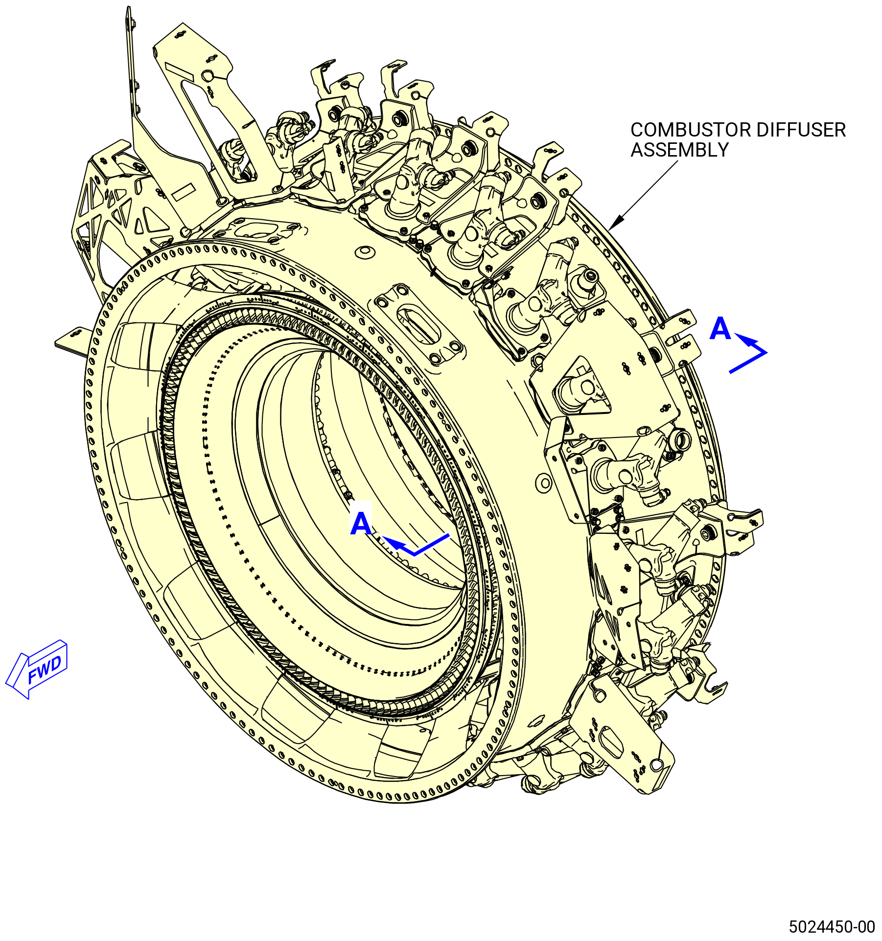
| COMBUSTOR DIFFUSER ASSEMBLY - ASSEMBLY 001 - CONFIGURATION 01 | ||
| GENX-1B ENGINE MANUAL | Dated: 12/06/2024 | |
| EM 72-41-00 , ASSEMBLY 001 | ||
| COMBUSTOR DIFFUSER ASSEMBLY - ASSEMBLY 001 - CONFIGURATION 01 | ||
| * * * FOR 1B/P/G03.1B/P/G04.1B/P1/G01 |
| TASK 72-41-00-440-801 |
| 1 . | General. |
| A. | This procedure gives instructions to assemble the combustor diffuser assembly. Refer to Figure 1001. |
| • |
|
| • |
|
| • |
|
| • |
|
| B. | Install all the bolts with the heads up and or forward unless specific instructions are given. |
| C. | Before installation, verify all rabbets and flanges are free of foreign material and raised metal. |
| WARNING: |
|
| WARNING: |
|
| D. | Clean the flanges with C04-002 Stoddard solvent, C04-035 isopropyl alcohol, or 50-50 blend of C04-035 isopropyl alcohol, and C04-228 denatured alcohol . |
| E. | Make sure that the condition of the stage 10 outlet guide vane honeycomb as either before the engine run or pre-grooved according to TASK 72-41-20-300-811 (72-41-20, REPAIR 010) if the combustor diffuser assembly will be installed with an engine run CDP rotating seal (01-460 , 72-31-00) (SIN 050NC). The CDP rotating seal teeth must be restored to piece part serviceability in order to correctly break in a new stage 10 outlet guide vane honeycomb. |
| 2 . | Tools, Equipment, and Materials. |
| NOTE: |
|
| A. | Tools and Equipment. |
| (1) | Special Tools. |
| (2) | Standard Tools and Equipment. |
|
| (3) | Locally Manufactured Tools. None. |
| B. | Consumable Materials. |
|
| C. | Referenced Procedures. |
|
| D. | Expendable Parts. |
|
| 3 . | Procedure. |
| Subtask 72-41-00-440-001 |
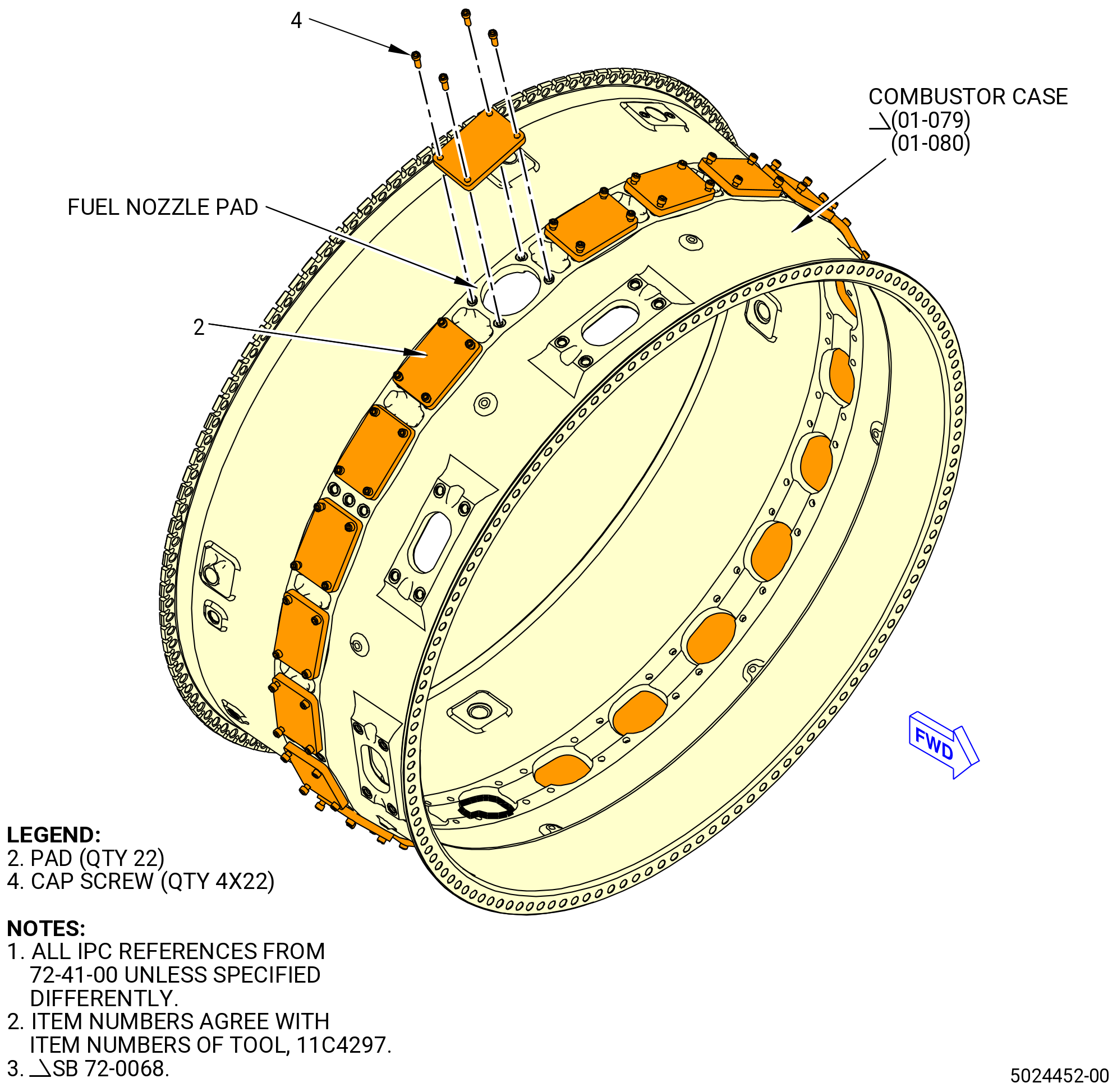
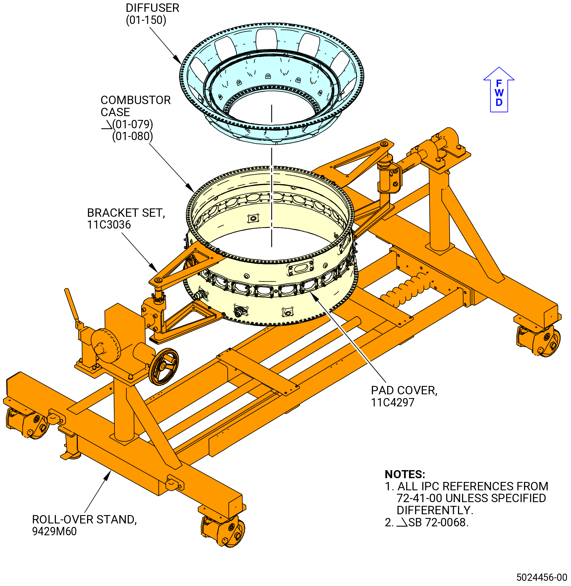
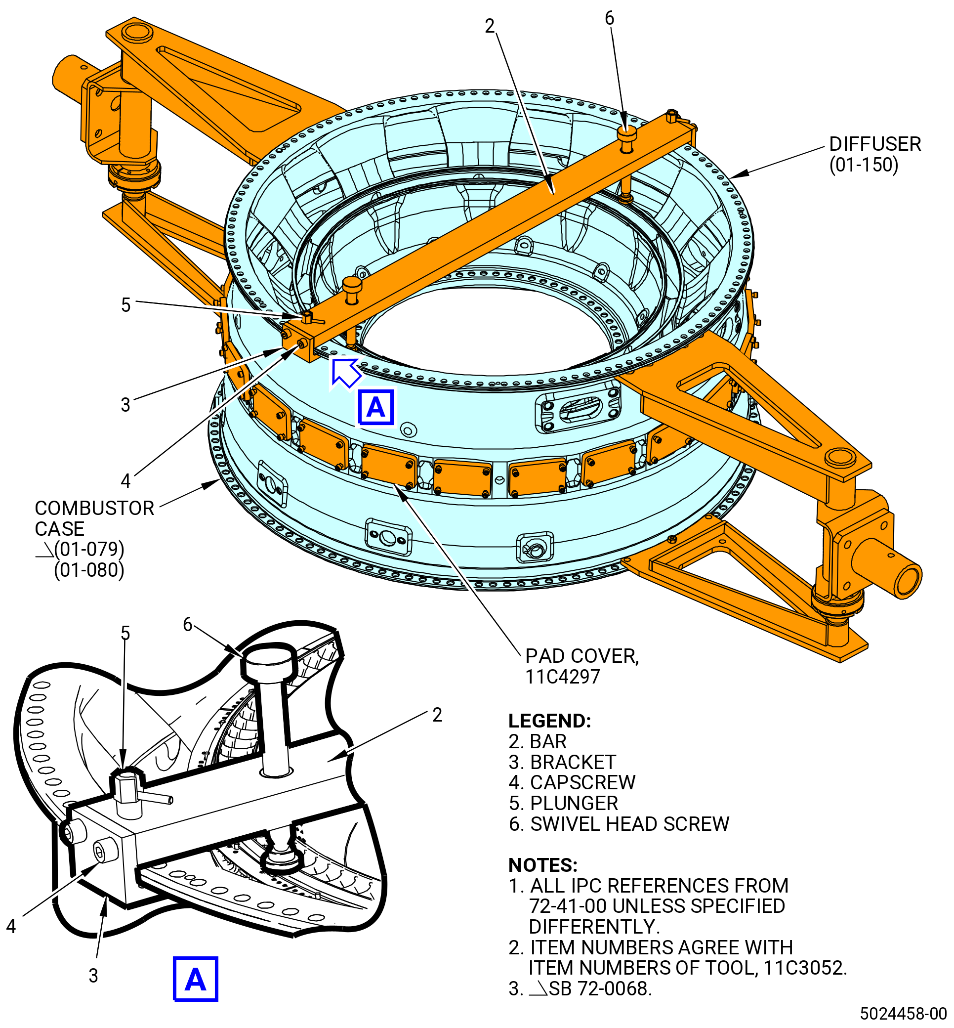
| A. | Install the 11C4297 pad covers on the combustor case (01-079) (SIN 12001) or (01-080) (SIN 12001). Refer to Figure 1002 and do as follows: |
| (1) | Install a pad (item 2) on the combustor case fuel nozzle pad using four cap screws (item 4). |
| (2) | Tighten the four cap screws (item 4) to 10 lb in. (1.1 N.m) to minimize wear on the threaded inserts in the combustor case. |
| (3) | Do again Subtask 72-41-00-440-001 (paragraph 3.A.(1) thru paragraph 3.A.(2)) for installation of each pad (item 2). |
| Subtask 72-41-00-440-174 |
| B. | Install the combustor case (01-079) (SIN 12001) or (01-080) (SIN 12001) in the 9429M60 roll-over stand as follows. If the 9429M60 roll-over stand is not available, the CDN can be assembled in the 11C4578 assembly stand. |
| (1) | Prepare the combustor case for installation into the roll-over stand as follows. Refer to Figure 1003. |
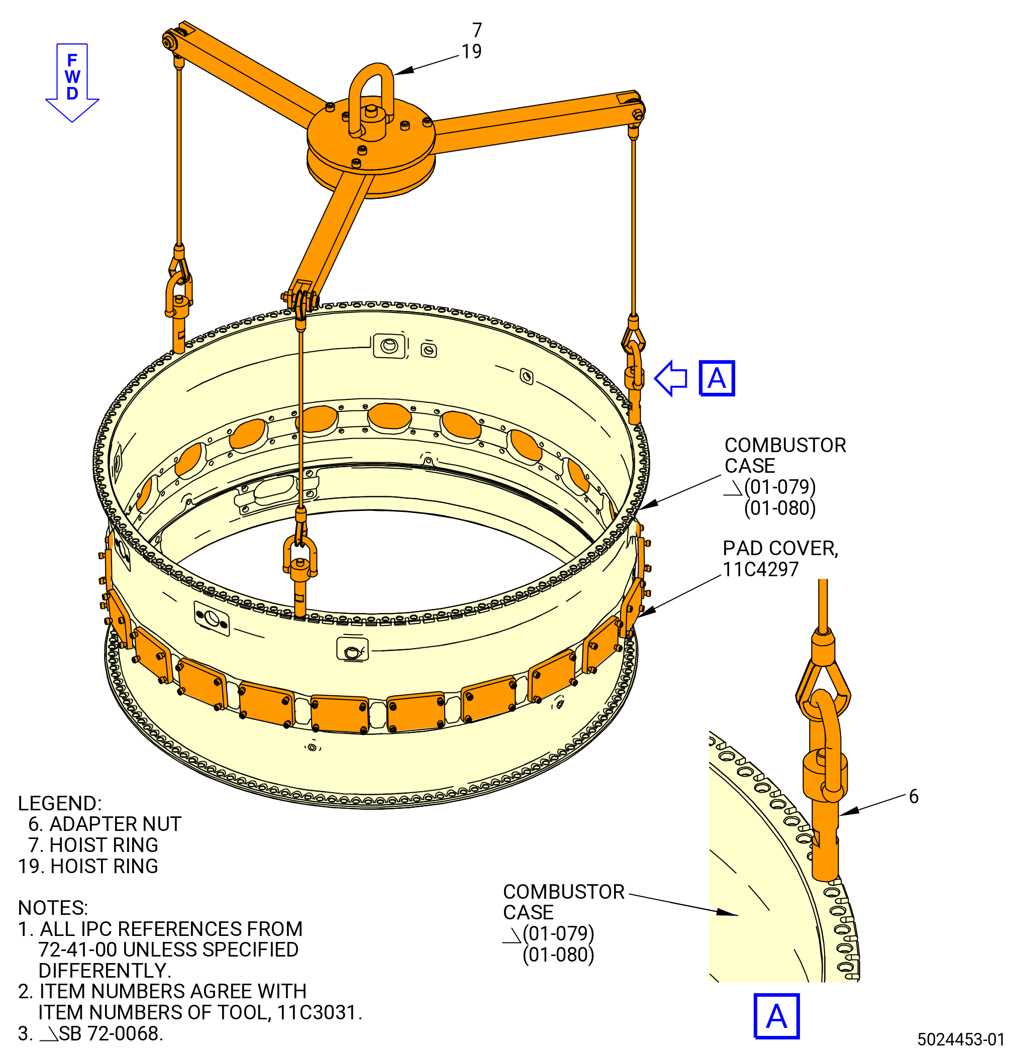
| (a) | Attach the 11C3031 lift fixture to the aft flange of the combustor case at locations away from the 12:00 o'clock and 6:00 o'clock positions as follows. Refer to Figure 1003. |
| NOTE: |
|
| 1 | Attach the hoist ring (item 7) or (item 19) on an overhead hoist and position the 11C3031 lift fixture above the aft end of the combustor case. |
| 2 | Lower the adapter nuts (item 6) to the bolts in the aft flange of the combustor case above the flange. |
| 3 | Align the adapter nuts (item 6) with boltholes in the flange. |
| 4 | Tighten the adapter nuts (item 6) by hand onto the bolts in the aft flange of the combustor case at three equally spaced locations until fully seated. |
| WARNING: |
|
| (b) | Use a hoist to lift the combustor case and lower it on a clean table. |
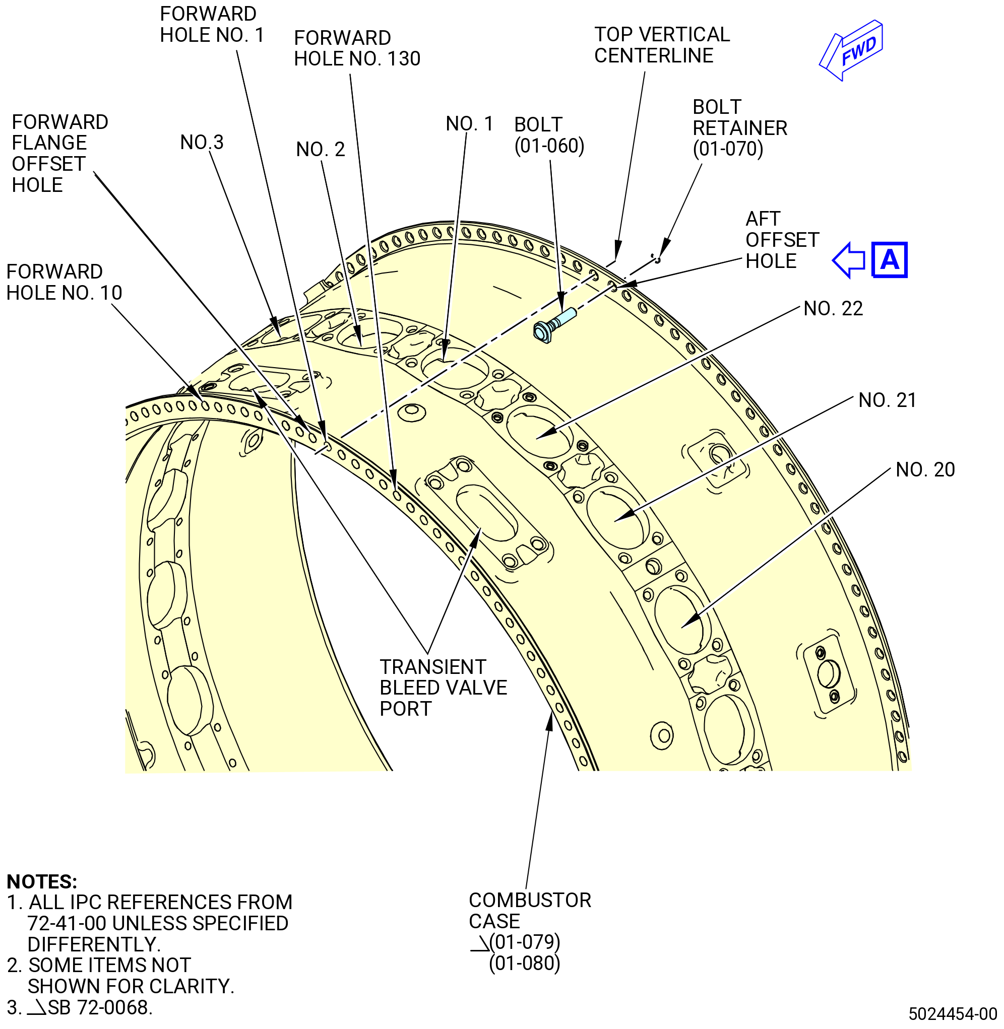
| (c) | Find the two transient bleed valve ports near the forward flange of the combustor case. The No. 1 fuel nozzle is aligned between the two transient bleed valve ports. Use a C05-003 pen to put a mark on the No. 1 fuel nozzle position. Refer to Figure 1004. |
| (d) | Use a C05-003 pen to put a mark on the remaining fuel nozzle positions, clockwise (CW) aft looking forward (ALF), from fuel nozzle No. 2 through fuel nozzle No. 22. |
| (e) | Find the center of the No. 1 fuel nozzle pad. This is the top vertical center line (TVCL) of the combustor case. Use a C05-003 pen to put a mark on the TVCL on the forward and aft flanges of the combustor case. |
| (f) | Find the bolthole at TVCL on the aft flange of the combustor case. The offset bolthole is the first bolthole counterclockwise (CCW) of the bolthole at TVCL, ALF. Use a C05-003 pen to put a mark on the offset bolthole location on the aft flange of the combustor case. |
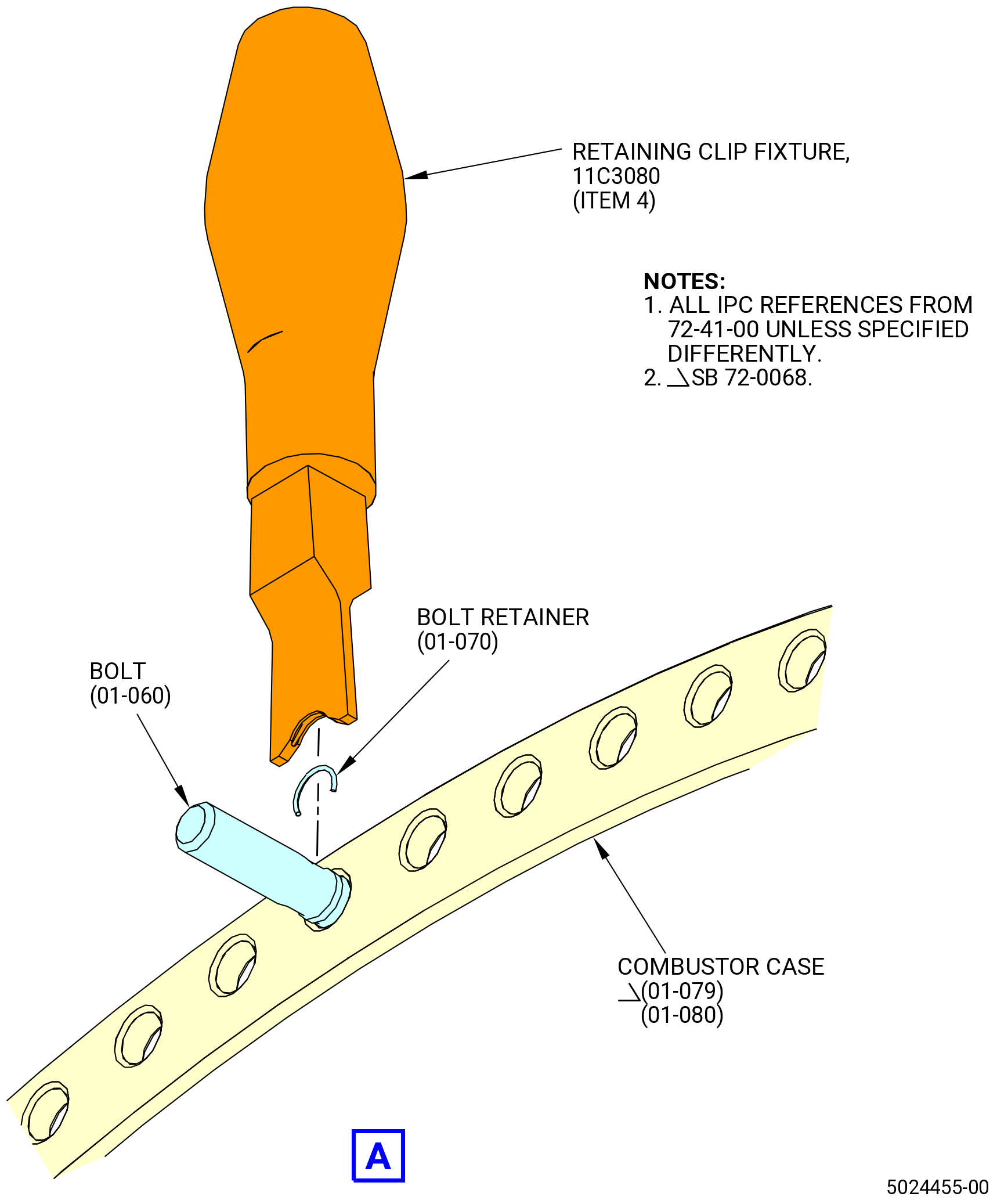
| (g) | Install 120 bolts (12024) through the boltholes in the aft flange with the bolt head flat against the case. Use installation tool (item 4) of the 11C3080 retaining clip fixture to install 120 bolt retainers (01-070) (SIN 12080) to attach bolts. |
| Subtask 72-41-00-440-002 |
| (2) | Install the 11C3036 bracket set on the combustor case as follows. Refer to Figure 1005. |
| (a) | Assemble the 11C3036 bracket set as follows: |
| NOTE: |
|
| NOTE: |
|
| 1 | Loosen the locknut (item 3) and turn the knurled nut (item 2) to retract the end plate of the aft adjustable bracket (item 21) or (item 24). |
| 2 | Install the mounting plate (item 13) or (item 22) to the end of the aft adjustable bracket with the cutouts. |
| 3 | Install capscrews (item 17) through the boltholes in the aft adjustable bracket and mounting plate with the bolt head against the aft adjustable bracket. Install nuts (item 11) on capscrews and tighten. |
| WARNING: |
|
| (b) | Lift the combustor case with the 11C3031 lift fixture. |
| (c) | Install the 11C3036 bracket set to the combustor case at the 3:00 o'clock position as follows: |
| 1 | Align the end plate of the forward fixed bracket (item 20) or (item 23) with the boltholes on the combustor case forward flange at the 3:00 o'clock position. |
| 2 | Move the end plate of the aft adjustable bracket (item 21) or (item 24) to the bolthole on the combustor case aft flange at the 3:00 o'clock position. |
| 3 | Turn the knurled nut (item 2) until the end plates are held tightly against the forward and aft flanges. Make sure that the 3:00 o'clock position marks on the brackets align with TVCL on the combustor case. Make sure that the two pins in the forward fixed bracket (item 20) or (item 23) engage the boltholes in the forward flange of the combustor case. |
| 4 | Turn the locknut (item 3) until it is against the knurled nut (item 2). |
| 5 | Align the boltholes in the clamping plate (item 14) with the alignment pins in the mounting plate (item 13) or (item 22) and the bolts in the combustor case. Install the clamping plate on the mounting plate with THIS SIDE UP WITHOUT COMBUSTOR mark on the outer side. |
| 6 | Install the capscrews (item 18) through the boltholes in the bracket, mounting plate, and clamping plate with the bolt head against the aft adjustable bracket. Install the nuts (item 11) on the capscrews and tighten them. |
| 7 | Torque the nuts (item 11) to 70-110 lb in. (7.9-12.4 N.m). |
| 8 | Install the capscrews (item 9) through the boltholes of the forward fixed bracket and the combustor case forward flange with the bolt head against the forward fixed bracket. |
| 9 | Attach the nuts (item 11) to the capscrews (item 9). |
| 10 | Torque the nuts (item 11) to 70-110 lb in. (7.9-12.4 N.m). |
| (d) | Install the bracket set to the combustor case at the 9:00 o'clock position as follows: |
| 1 | Align the end plate of the forward fixed bracket (item 20) or (item 23) with the boltholes on the combustor case forward flange at the 9:00 o'clock position. |
| 2 | Move the end plate of the aft adjustable bracket (item 21) or (item 24) to the bolthole on the combustor case aft flange at the 9:00 o'clock position. |
| 3 | Turn the knurled nut (item 2) until the end plates are held tightly against the forward and aft flanges. Make sure that the 9:00 o'clock position marks on the brackets align with TVCL on the combustor case. Make sure that the two pins in the forward fixed bracket (item 20) or (item 23) engage the boltholes in the forward flange of the combustor case. |
| 4 | Turn the locknut (item 3) until it is against the knurled nut (item 2). |
| 5 | Align the boltholes in the clamping plate (item 14) with the alignment pins in the mounting plate (item 13) or (item 22) and the bolts in the combustor case. Install clamping plate on the mounting plate with THIS SIDE UP WITHOUT COMBUSTOR mark on the outer side. |
| 6 | Install the capscrews (item 18) through the boltholes in the bracket, mounting plate, and clamping plate with the bolt head against the aft adjustable bracket. Install the nuts (item 11) on the capscrews and tighten them. |
| 7 | Torque the nuts (item 11) to 70-110 lb in. (7.9-12.4 N.m). |
| 8 | Install the capscrews (item 9) through the boltholes of the forward fixed bracket and the combustor case forward flange with the bolt head against the forward fixed bracket. |
| 9 | Attach the nuts (item 11) to the capscrews (item 9). |
| 10 | Torque the nuts (item 11) to 70-110 lb in. (7.9-12.4 N.m). |
| Subtask 72-41-00-440-006 |
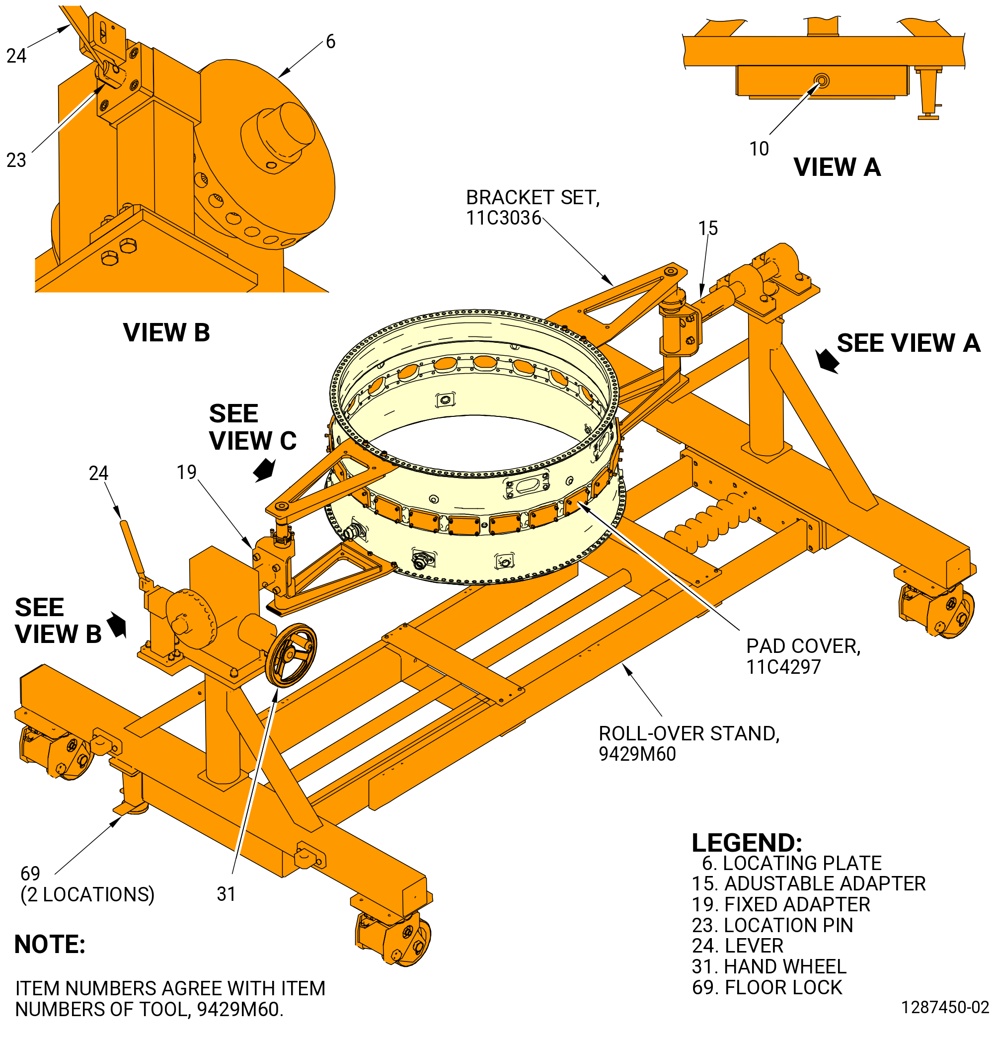
| (3) | Install the combustor case in the 9429M60 roll-over stand as follows. Refer to Figure 1005. |
| CAUTION: |
|
| (a) | Lower the floor locks (item 69) of the 9429M60 roll-over stand until they touch the floor. The floor locks must stay in contact with the floor to prevent movement of the roll-over stand. Make sure that the roll-over stand is level. |
| (b) | Put the ends of the adapters (item 15) and (item 19) square to the floor as follows: |
| 1 | Push the lever (item 24) to disengage the locating pin (item 23) from the locating plate (item 6) and turn the handle (item 31) until the square plates of the adapters are square to the floor. |
| CAUTION: |
|
| 2 | Release the lever (item 24) and turn handle back and forth until the locating pin (item 23) engages the locating plate (item 6). |
| NOTE: |
|
| WARNING: |
|
| (c) | Move the combustor case to the 9429M60 roll-over stand. |
| (d) | Align one bracket of the 11C3036 bracket set with the end of the fixed adapter (item 19) of the 9429M60 roll-over stand. |
| (e) | Align the other bracket of the 11C3036 bracket set with the end of the adjustable adapter (item 15) of the 9429M60 roll-over stand. |
| (f) | Install the hardware that attaches the 11C3036 bracket set to the 9429M60 roll-over stand as follows: |
| 1 | Attach the bracket to the fixed adapter (item 19) with the capscrews (item 10) and nuts (item 12). |
| 2 | Attach the bracket to the adjustable adapter (item 15) with the capscrews (item 10) and nuts (item 12). |
| 3 | Torque the nuts (item 12) to 420-510 lb in. (47.5-57.6 N.m). |
| (4) | Remove the 11C3031 lift fixture from the combustor case. |
| Subtask 72-41-00-440-012 |
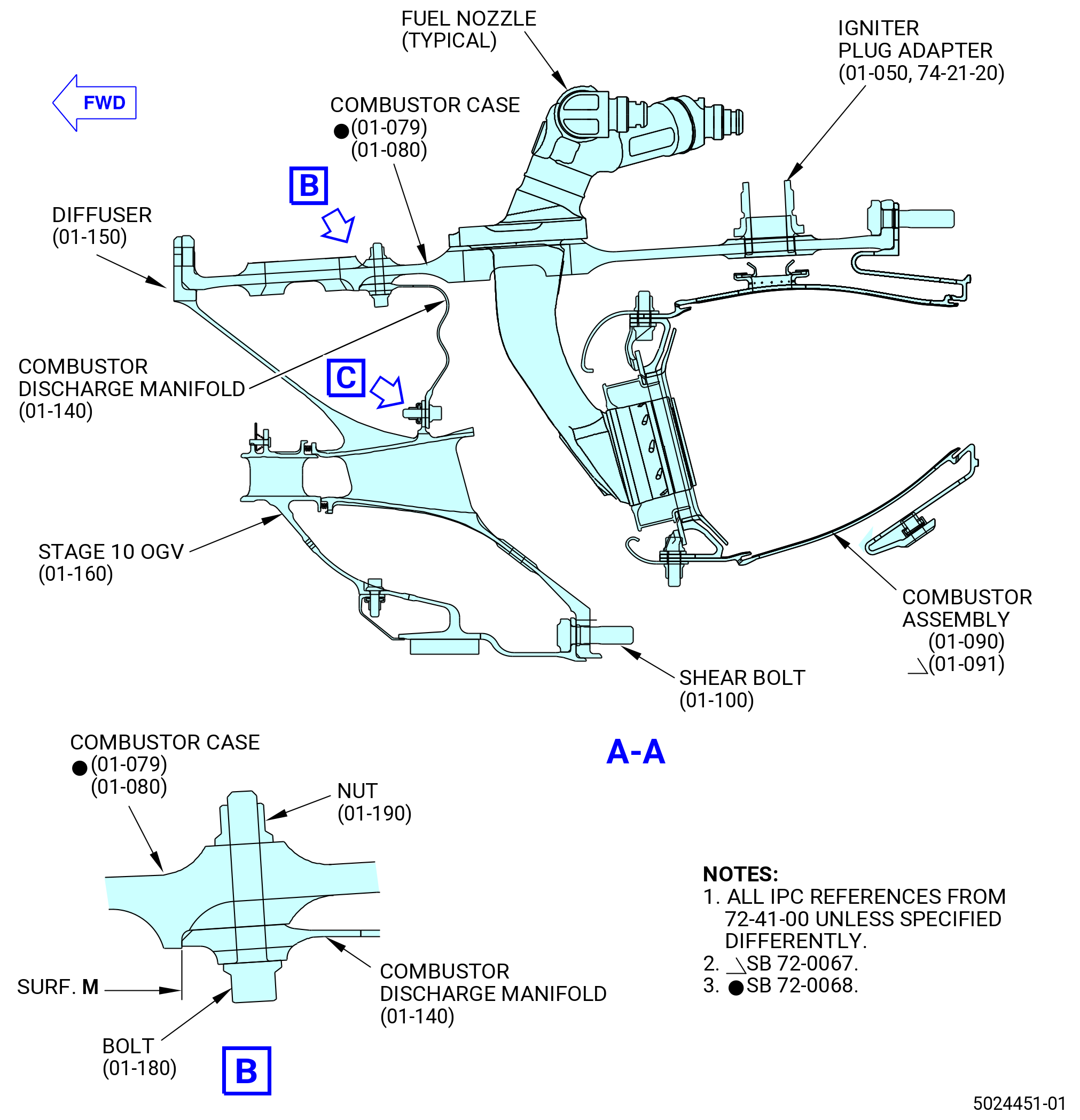
| C. | Install the diffuser (01-150) (SIN 09800) in the combustor case (01-079) (SIN 12001) or (01-080) (SIN 12001). Refer to Figure 1006 and do as follows: |
| WARNING: |
|
| CAUTION: |
|
| (1) | Turn the combustor case in the 9429M60 roll-over stand forward end up as follows. Refer to Figure 1005. |
| (a) | Make sure that the combustor case is correctly installed in the 11C3036 bracket set and the 9429M60 roll-over stand. Refer to Subtask 72-41-00-440-002 (paragraph 3.A.(2)) and Subtask 72-41-00-440-013 (paragraph 3.D.). |
| (b) | Push the lever (item 24) to unlock the hand wheel (item 31). |
| (c) | Turn the hand wheel (item 31) until the combustor case is in the forward end up position. |
| CAUTION: |
|
| (d) | Release the lever (item 24) and turn the handle back and forth until the locating pin (item 23) engages the locating plate (item 6). |
| NOTE: |
|
| (2) | Find the bolthole at TVCL on the forward flange of the combustor case. The offset bolthole is the first bolthole CCW of the bolthole at TVCL, forward looking aft (FLA). Use a C05-003 pen to put a mark on the offset bolthole location on the forward flange of the combustor case. |
| WARNING: |
|
| WARNING: |
|
| (3) | Clean the diffuser flange and combustor case flange with C04-002 Stoddard solvent, or a 50-50 blend of C04-035 isopropyl alcohol, and C04-228 denatured alcohol, or C04-035 isopropyl alcohol. Refer to TASK 70-20-00-100-001 (CLEANING ENGINE PARTS). |
| (4) | Make sure that there is no unwanted material or raised metal on the rabbet or structural flanges. Refer to TASK 70-42-00-350-002 (BLENDING AND REMOVAL OF HIGH METAL PROCEDURES). |
| (5) | Find the offset bolthole in the diffuser flange as follows: |
| (a) | Find the part mark on the inside surface of the diffuser near the aft flange. This is the location of the No. 1 strut. |
| (b) | Find the bolthole at the centerline of the No. 1 strut of the diffuser. The offset bolthole is the fourth bolthole CCW of the bolthole at the centerline of the No. 1 strut, FLA. Use a C05-003 pen to put a mark on the offset bolthole location on the forward flange of the diffuser. |
| (6) | Decrease the temperature of the forward flange of the diffuser as follows: |
| NOTE: |
|
| WARNING: |
|
| (a) | Apply dry ice to the forward flange of the diffuser for 20 minutes. |
| (7) | Use nylon straps to lift the diffuser and align the offset hole with the combustor case offset hole. |
| NOTE: |
|
| (8) | Lower the diffuser into the combustor case. Make sure that the offset holes align. |
| (9) | Attach the diffuser to the combustor case with the 0.375-24 UNJF slave bolts and nuts at 12 equally spaced locations. Tighten the slave nuts until the diffuser and combustor case flanges touch. |
| (10) | Let the temperature of the parts return to ambient temperature. |
| (11) | Use a 0.001 inch (0.03 mm) feeler gage to make sure that the diffuser is fully against the combustor case. |
| Subtask 72-41-00-440-169 |
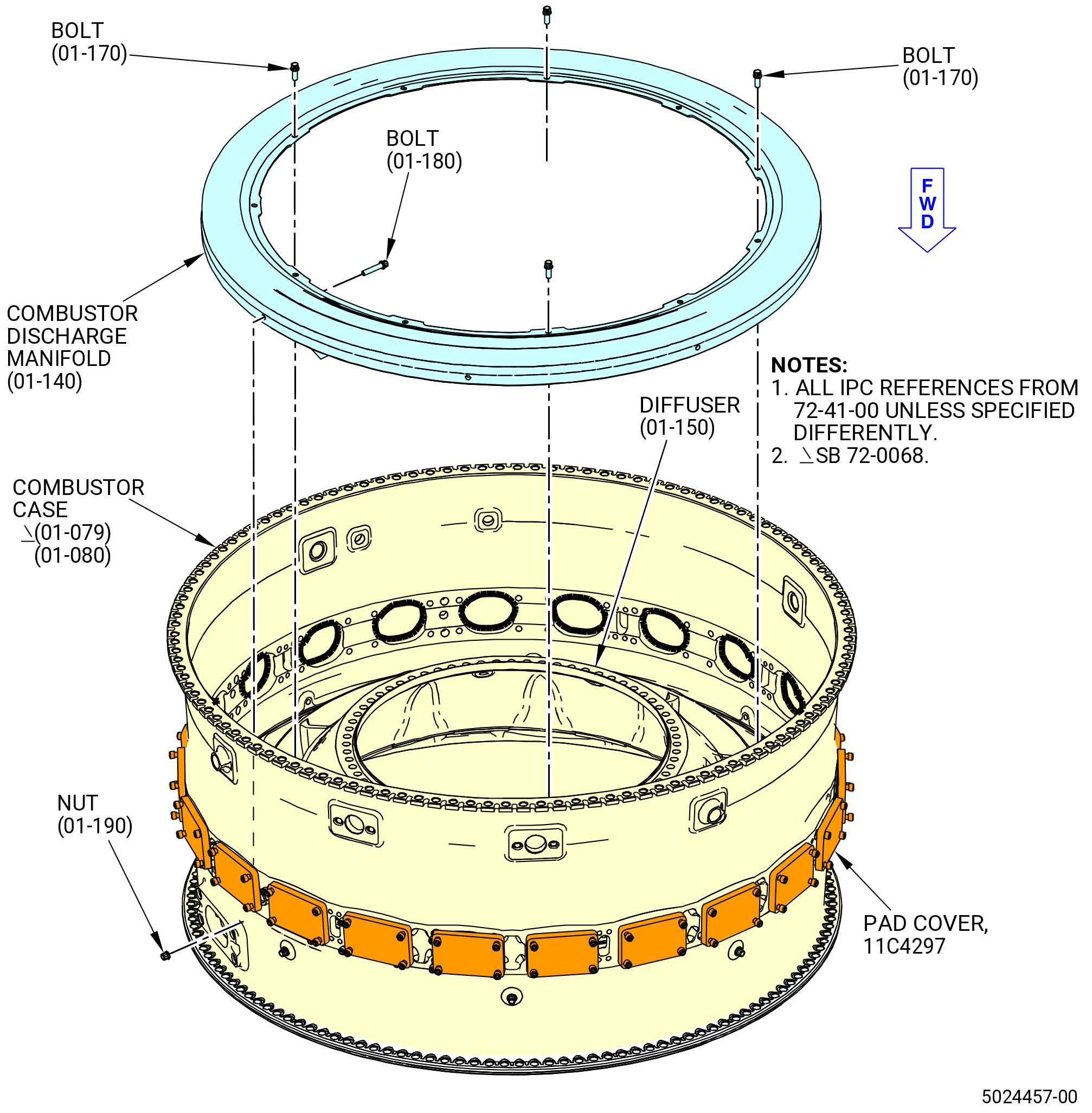
| D. | Install the combustor discharge manifold (01-140) (SIN 09801) in the combustor case (01-079) (SIN 12001) or (01-080) (SIN 12001). Refer to Figure 1007 and do as follows: |
| (1) | Turn the combustor case in the 9429M60 roll-over stand forward end down. |
| WARNING: |
|
| WARNING: |
|
| (2) | Clean the diffuser flange and combustor case flange with C04-002 Stoddard solvent, or a 50-50 blend of C04-035 isopropyl alcohol, and C04-228 denatured alcohol, or C04-035 isopropyl alcohol. Refer to TASK 70-20-00-100-001 (CLEANING ENGINE PARTS). Refer to TASK 70-20-00-100-001 (CLEANING ENGINE PARTS). |
| WARNING: |
|
| CAUTION: |
|
| (3) | Apply C02-097 lubricant or optionally C02-058 lubricant to the threads of 11 bolts (01-170) (SIN 09820). |
| (4) | Install the combustor discharge manifold in the combustor case on the diffuser (09800). |
| Subtask 72-41-00-440-201 |
| * * * PRE SB 72-0530 |
| (5) | Attach the combustor discharge manifold to the diffuser (09800) with the bolts (09820). Torque the bolts to 52-60 lb in. (5.9-6.8 N.m) in a criss-cross pattern. |
| (6) | Make sure that the combustor discharge manifold is fully against the combustor case at surface M. Use a 0.001 inch (0.03 mm) feeler gage. |
| (7) | Torque the bolts (09820) to 69-81 lb in. (7.8-9.2 N.m) in a criss-cross pattern. |
| * * * END PRE SB 72-0530 |
| Subtask 72-41-00-440-202 |
| * * * SB 72-0530 |
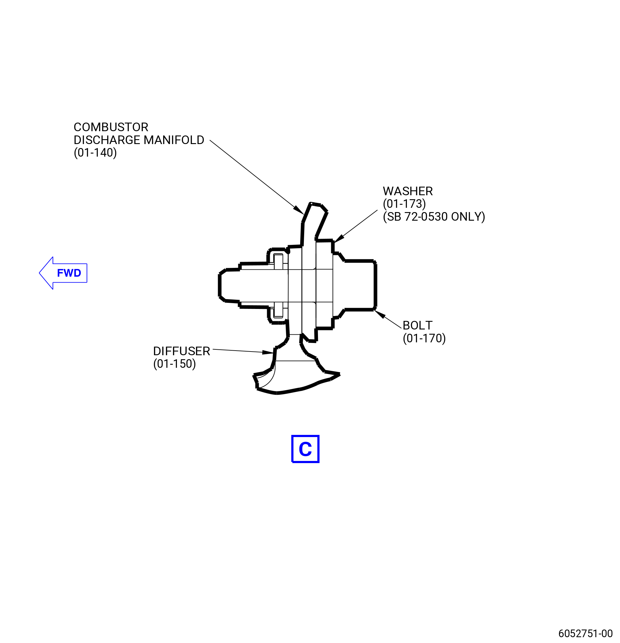
| (8) | Attach the combustor discharge manifold to the diffuser (01-150) (SIN 09800) or (01-155) (SIN 09800) with 11 bolts (01-170A) (SIN 09820) and washers (01-173) (SIN 09830). The washers go between the bolt head and the CDP manifold, refer to Figure 1001. Torque the bolts to 52 to 60 lb in. (5.9 to 6.8 Nm) in a criss-cross pattern. |
| (9) | Make sure that the combustor discharge manifold is fully against the combustor case at surface M. Use a 0.001 inch (0.03 mm) feeler gage. Refer to Figure 1001. |
| (10) | Torque the bolts (01-170A) (SIN 09820) to 97 to 113 lb in. (11.0 to 12.8 Nm) in a criss-cross pattern. |
| * * * END SB 72-0530 |
| Subtask 72-41-00-440-203 |
| WARNING: |
|
| CAUTION: |
|
| (11) | Apply C02-097 lubricant or optionally C02-058 lubricant to the threads and washer face of six self-locking nuts (nuts) (01-190) (SIN 09841). |
| (12) | Install bolts (09821) through the combustor discharge manifold and the combustor case. |
| WARNING: |
|
| CAUTION: |
|
| (13) | Apply C02-097 lubricant or optionally C02-058 lubricant to the threads of six bolts (01-180) (SIN 09821) after they are installed in the combustor case. Do not put lubricant between the flanges of the combustor case and combustor discharge manifold. |
| (14) | Install nuts (09841) on the bolts (09821). |
| (15) | Torque the nuts (09841) to 69-81 lb in. (7.8-9.2 N.m) in a criss-cross pattern. |
| NOTE: |
|
| (16) | Remove unwanted lubricant from the combustor case. |
| Subtask 72-41-00-440-013 |
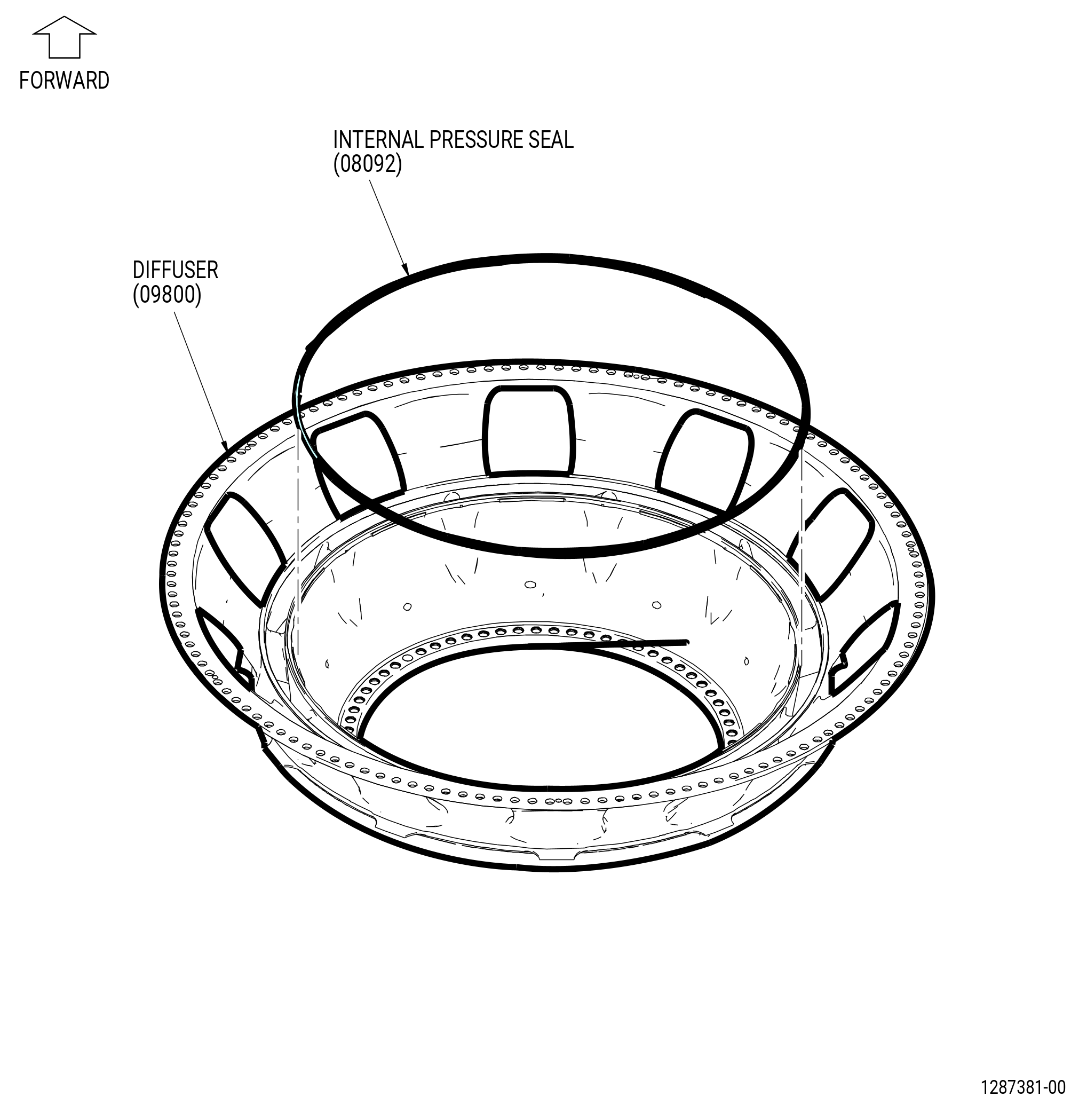
| E. | Attach the internal pressure seal (01-130) (SIN 08092) to the diffuser (09800) as follows. Refer to Figure 1008. |
| (1) | Turn the combustor case in the 9429M60 roll-over stand forward end up. |
| (2) | Apply C01-037 adhesive or C10-154 beeswax in small quantities to the internal pressure seal flange at locations spaced 6.0 inches (152.4 mm) apart. |
| (3) | Install the internal pressure seal into the internal seal flange of the diffuser. |
| (4) | Make sure that the internal pressure seal is fully against the flange of the diffuser. |
| (5) | Remove the unwanted adhesive or beeswax from the internal pressure seal and the flange area of the diffuser. |
| Subtask 72-41-00-440-207 |
| F. | Optional Procedure. Pre-groove the honeycomb for the assembly with engine run CDP rotating seal (01-460 , 72-31-00) (SIN 050NC). Refer to TASK 72-41-20-300-811 (72-41-20, REPAIR 010). |
| NOTE: |
|
| Subtask 72-41-00-440-104 |
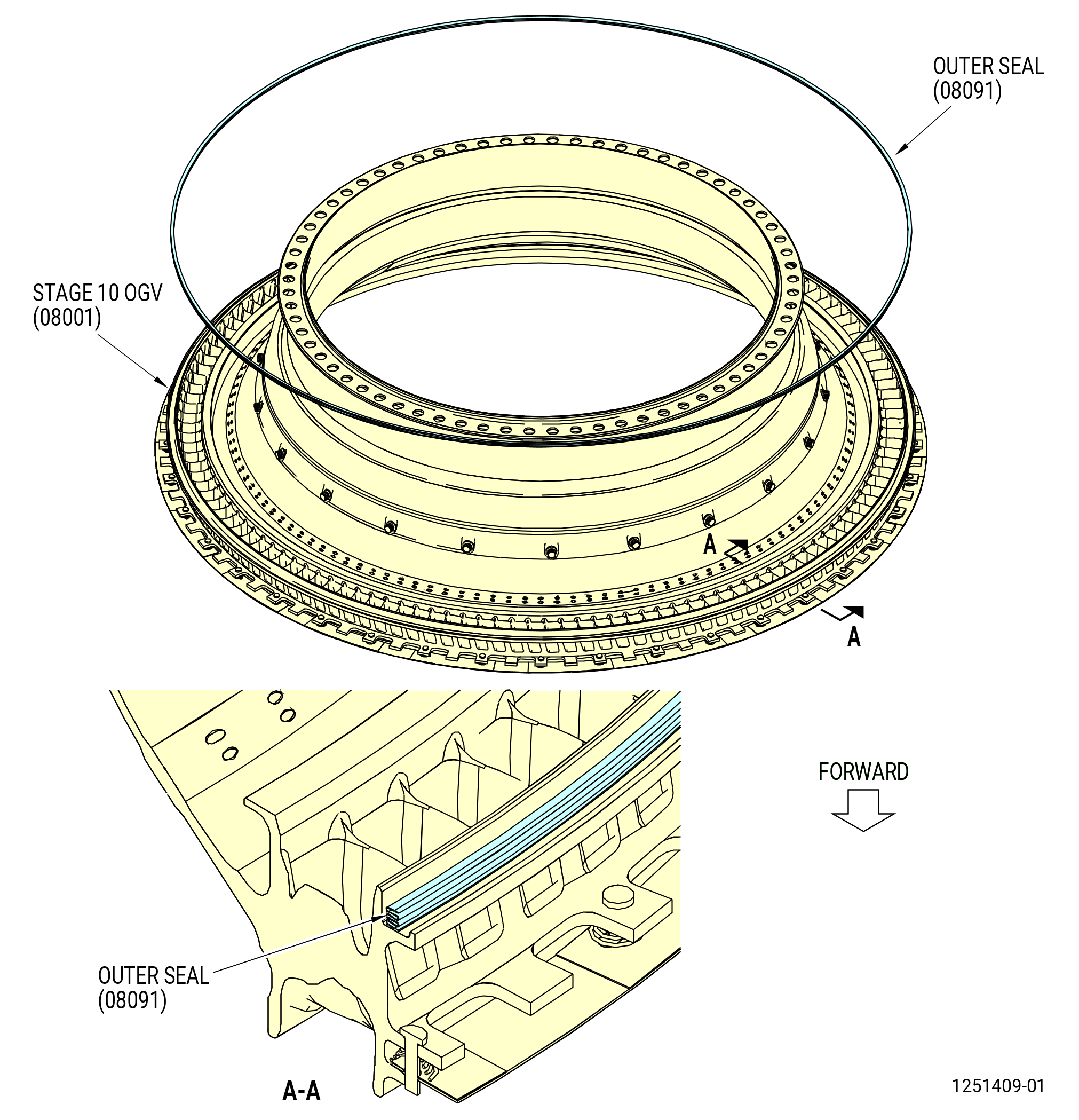
| G. | Install the external pressure seal (01-120) (SIN 08091) into the stage 10 outlet guide vane (OGV) (08001) as follows. Refer to Figure 1009. |
| WARNING: |
|
| (1) | Put the stage 10 OGV aft end up on a clean work table. |
| (2) | Apply C01-037 adhesive or C10-154 beeswax in small amounts to the stage 10 OGV external pressure seal flange at locations spaced 6.0 inches (152.4 mm) apart. |
| (3) | Install the external pressure seal into the flange of the stage 10 OGV. |
| (4) | Make sure that the external pressure seal is fully against the flange of the stage 10 OGV. |
| (5) | Remove the unwanted adhesive or beeswax from the external pressure seal and the flange area of the stage 10 OGV. |
| Subtask 72-41-00-440-014 |
| CAUTION: |
|
| H. | Install the shear bolts (01-100) (SIN 17221) and bolt retainers (01-110) (SIN 17291) into the aft flange of the stage 10 OGV (08001). Use installation tool (item 4) of the 11C3080 retaining clip fixture to install bolt retainers (01-110) (SIN 17291). Refer to Figure 1010. |
| Subtask 72-41-00-440-016 |
| I. | Alternative Procedure Available. Install the 11C3079 OGV lift fixture on the stage 10 OGV (08001) as follows. Refer to Figure 1011. |
| (1) | Put the stage 10 OGV on a clean work table, forward end up. |
| (2) | Put the stage 10 OGV on blocks so there is space below the aft flange to permit installation of the 11C3079 OGV lift fixture. |
| (3) | Turn the four vertical hand knobs (item 18) on the extension rods (item 5) CW to fully retract the segments of the lower clamp plate (item 25). |
| (4) | Turn the four horizontal hand knobs (item 18) CW to fully retract the segments of the upper clamp plate (item 24). |
| (5) | Turn the four knurled knobs (item 26) CCW to loosen the positioning stops (item 9). |
| (6) | Turn the adjustment nut (item 10) with the torque handle (item 4) to move the lower guide plate (item 6) and the upper guide plate (item 7) apart approximately 0.25 inch (6.4 mm). |
| (7) | Turn the hex head screw on the side of the fixator (item 44). |
| (8) | Turn the nut (item 42) CCW to lift it above the fixator (item 44). |
| (9) | Remove the ball lock pins (item 51) from the storage stand (item 31). |
| (10) | Move the retaining plates of the storage stand from the support beam (item 2). |
| WARNING: |
|
| (11) | Attach an overhead hoist to the lift eye (item 46) and lift the 11C3079 OGV lift fixture from the storage stand (item 31). |
| (12) | Align the 11C3079 OGV lift fixture above the stage 10 OGV. |
| (13) | Lower the 11C3079 OGV lift fixture on the stage 10 OGV. The positioning stops (item 9) will touch the forward face of the stage 10 OGV. |
| (14) | Adjust the lower clamp plate (item 25) raidially until the segments lightly touch the inside diameter of the stage 10 OGV. Turn the nut (item 42) to adjust the axial position of the lower clamp plate. |
| (15) | Lower the fixator (item 44) into position and turn the nut (item 42) until the bottom edge of the lower clamp plate (item 25) is fully against the bottom edge of the stage 10 OGV. |
| (16) | Look through the holes in the upper guide plate (item 7) with a white light to make sure that the lower clamp plate is fully against the stage 10 OGV. Make sure that you can see the white scribed circle line on the lower guide plate. Make sure that the scribed circle line and the lower clamp plate (item 25) are concentric. |
| (17) | Turn the vertical hand knobs (item 18) CCW to tighten the lower clamp plate (item 25) against the stage 10 OGV. |
| (18) | Turn the horizontal knobs (item 18) CCW and move the upper clamp plate segments (item 24) until they lightly touch the inside diameter groove of the stage 10 OGV. |
| (19) | Use torque handle (item 4) to turn the adjustment nut (item 10) up or down to align the radius of the 11C3079 OGV lift fixture with the radius of the stage 10 OGV. |
| (20) | Turn the horizontal knobs (item 18) CCW and tighten the upper clamp plate segments (item 24) against the inside diameter groove of the stage 10 OGV. |
| (21) | Look at the white circle line to make sure that the plates are concentric. |
| (22) | Move the positioning stops (item 9) above the stage 10 OGV flange. Tighten the knurled knobs (item 26) to hold the guide plates in position. |
| Subtask 72-41-00-440-171 |
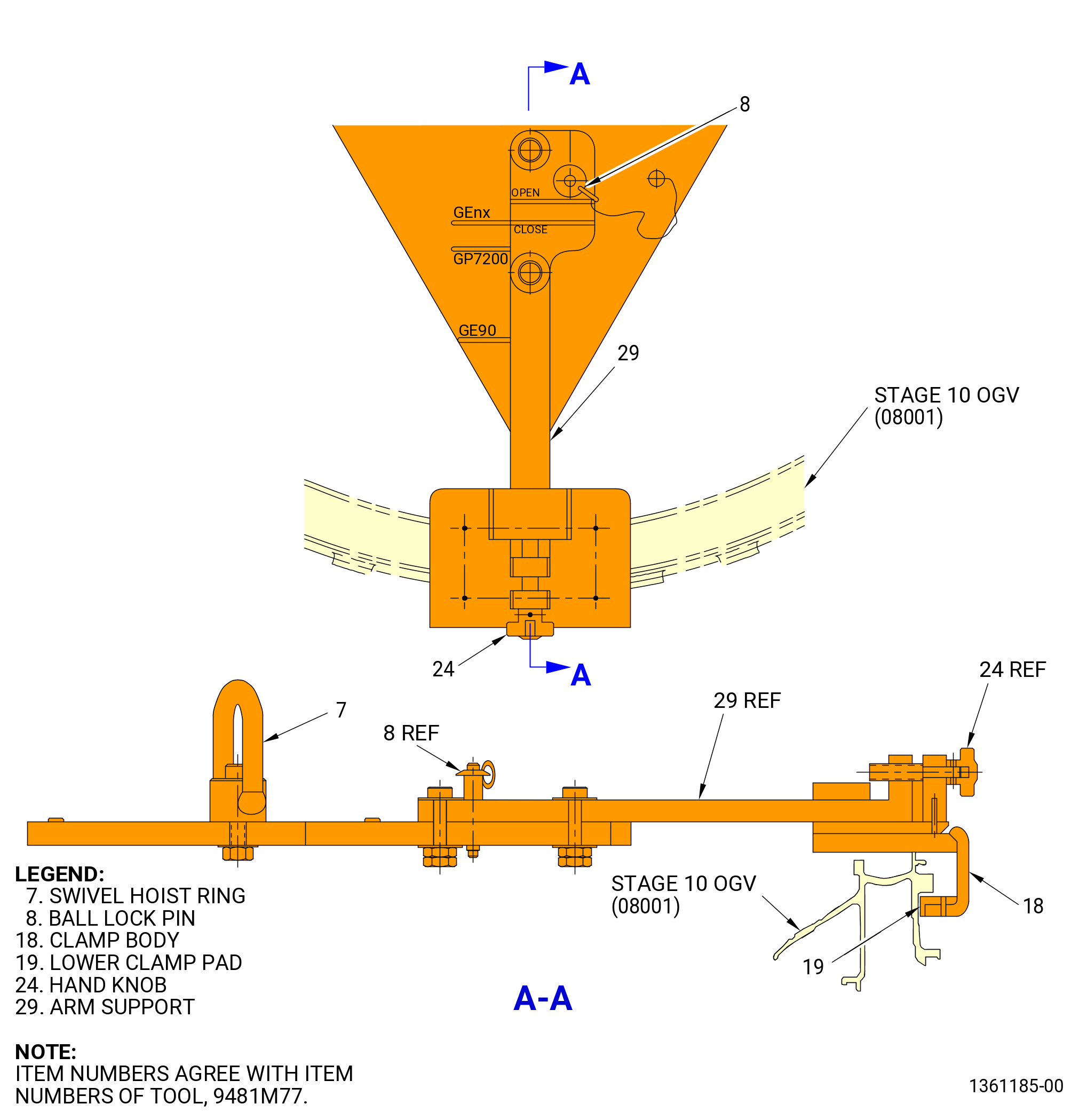
| I.A. | Alternative Procedure. Install the 9481M77 OGV lift fixture on the stage 10 OGV (08001) as follows. Refer to Figure 1012. |
| (1) | Remove the ball-lock pins (item 8) from the three arm supports (item 29). |
| (2) | Turn each hand knob (item 24) to open the engagement diameter between the stage 10 OGV and the clamp body (item 18). |
| (3) | Put the 9481M77 OGV lift fixture on the stage 10 OGV. Make sure that the arm supports (item 29) are extended to the OPEN position for GEnx Engine application. |
| (4) | Install the arm supports (item 29) on the OGV as follows: |
| (a) | Put the arm supports (item 29) in the CLOSED position for the GEnx Engine application. |
| (b) | Insert the ball-lock pins (item 8) into the arm supports (item 29). |
| WARNING: |
|
| WARNING: |
|
| (5) | Turn the hand knob (item 24) to adjust the clamp body (item 18) until there is zero gap between the lower clamp pad (item 19) and the stage 10 OGV. |
| Subtask 72-41-00-440-020 |
| J. | Alternative Procedure Available. Install the stage 10 OGV (08001) in the diffuser (09800) with the 11C3079 OGV lift fixture as follows: |
| WARNING: |
|
| (1) | Clean mating surfaces with C04-035 isopropyl alcohol. |
| WARNING: |
|
| (2) | Use dry ice to decrease the temperature of the stage 10 OGV flange. |
| (3) | Make sure that you remove all ice from the flange and seal surfaces of the stage 10 OGV. |
| WARNING: |
|
| (4) | Use a hoist and lift straps attached to the vanes to lower the 11C3079 OGV lift fixture to the combustor case (01-079) (SIN 12001) or (01-080) (SIN 12001) as follows: |
| (a) | Align the shear bolts (01-100) (SIN 17221) in the stage 10 OGV with the boltholes in the inner flange of the diffuser. Refer to Figure 1001. |
| NOTE: |
|
| (b) | Align the two pins of the support beam (item 2) with the boltholes in the outer flange of the diffuser. Refer to Figure 1011. |
| (c) | If necessary turn the nut (item 42) to install the stage 10 OGV. |
| (5) | Install the capscrews (item 37) through the CDN flange and into the support beam (item 2) of the 11C3079 OGV lift fixture. Tighten the capscrews (item 37) until they touch the combustor case (01-079) (SIN 12001) or (01-080) (SIN 12001). Refer to Figure 1011. |
| (6) | Apply C02-058 lubricant or C02-097 lubricant to the threads and friction surfaces of the shear bolts (01-100) (SIN 17221). Refer to Figure 1010. |
| (7) | Install the slave washers and the nuts on the shear bolts (01-100) (SIN 17221). Tighten the slave nuts to put the stage 10 OGV against the diffuser. |
| (8) | Keep the 11C3079 OGV lift fixture in the same position until the parts return to room temperature. |
| (9) | Remove the 11C3079 OGV lift fixture as follows: |
| (a) | Remove the capscrews (item 37) from the support beam (item 2) of 11C3079 OGV lift fixture. Refer to Figure 1011. |
| (b) | Turn the four vertical hand knobs (item 18) on the extension rods (item 5) CW to fully retract the segments of the lower clamp plate (item 25). |
| (c) | Turn the four horizontal hand knobs (item 18) CW to fully retract the segments of the upper clamp plate (item 24). |
| (d) | Turn the four knurled knobs (item 26) CCW to loosen the positioning stops (item 9). |
| (e) | Use the torque handle (item 4) to turn the adjustment nut (item 10) CCW until the shoulder face of the lower clamp plate (item 25) is disengaged from the stage 10 OGV. |
| WARNING: |
|
| (f) | Lift the 11C3079 OGV lift fixture from the stage 10 OGV. |
| (g) | Put the 11C3079 OGV lift fixture in the storage stand (item 31). |
| (h) | Put the retaining plates of the storage stand in position on the support beam. |
| (i) | Install the two ball lock pins (item 51) in the retaining plates to attach the support beam (item 2) to the storage stand (item 31). |
| (j) | Remove the hoist from the lift eye (item 46). |
| Subtask 72-41-00-440-172 |
| J.A. | Alternative Procedure. Install the stage 10 OGV (08001) in the diffuser (09800) with the 9481M77 OGV lift fixture as follows. Refer to Figure 1012. |
| (1) | Connect the swivel hoist ring (item 7) to an overhead hoist with minimum lift capacity of 126 kg (278 lb). |
| (2) | Put the stage 10 OGV in the diffuser as follows: |
| WARNING: |
|
| WARNING: |
|
| (a) | Use dry ice to decrease the temperature of the stage 10 OGV flange. |
| (b) | Make sure to remove all ice from the flange and seal surfaces of the stage 10 OGV. |
| WARNING: |
|
| (c) | Use the hoist to lower the 9481M77 OGV lift fixture and stage 10 OGV. |
| (d) | Align the shear bolts (01-100) (SIN 17221) in the stage 10 OGV with the boltholes in the inner flange of the diffuser. Refer to Figure 1001. |
| (e) | Apply C02-058 lubricant or C02-097 lubricant to the threads and friction surfaces of the shear bolts (01-100) (SIN 17221). Refer to Figure 1010. |
| (f) | Install the slave washers and the nuts on the shear bolts (01-100) (SIN 17221). Tighten the slave nuts to put the stage 10 OGV against the diffuser. |
| (g) | Keep the 9481M77 OGV lift fixture in the same position until the parts return to room temperature. |
| (h) | Remove the hoist from the swivel hoist ring (item 7). |
| (3) | Open the clamp body (item 18) by turning the hand knob (item 24) until there is sufficient clearance between the lower clamp pads (item 19) and the stage 10 OGV to remove the tool. |
| (4) | Remove the arm supports (item 29) from the stage 10 OGV as follows: |
| (a) | Remove the ball-lock pins (item 8). |
| (b) | Move the arm supports radially outwards until they are in the OPEN position for the GEnx Engine application. |
| (c) | Fully re-insert the ball-lock pins (item 8). |
| (5) | Remove the 9481M77 OGV lift fixture from the stage 10 OGV and store the 9481M77 OGV lift fixture tool. |
| Subtask 72-41-00-440-021 |
| K. | Install the 11C3052 restraint fixture to hold the stage 10 OGV (08001) and the diffuser (09800) in position as follows. Refer to Figure 1013. |
| (1) | Retract the swivel head screws (item 6). |
| (2) | Retract the plunger (item 5). |
| (3) | Make sure that the side bracket (item 3) is attached to the bar (item 2) with the capscrews (item 4). Make sure that the L-shaped part of the bracket is below the bar until it engages the flange of the combustor case (01-079) (SIN 12001) or (01-080) (SIN 12001). |
| (4) | Remove the slave nuts, bolts, and washers from the forward flange of the combustor case (01-079) (SIN 12001) or (01-080) (SIN 12001) to let the restraint fixture be installed. |
| (5) | Put the bar (item 2) on the forward flange of the combustor case (01-079) (SIN 12001) or (01-080) (SIN 12001) at approximately 4:00 o'clock and 8:00 o'clock positions. Make sure that the swivel feet of the swivel head screws (item 6) are inside the combustor case and the side brackets (item 3) are outside the combustor case. |
| (6) | Move the bar (item 2) to the center of the combustor case (01-079) (SIN 12001) or (01-080) (SIN 12001) with the side brackets (item 3) at approximately 3:00 o'clock and 9:00 o'clock positions. Align the plunger (item 5) with the holes in the combustor case 180 degrees apart and engage the plungers in the holes. |
| (7) | Turn each swivel head screw (item 6), one after another, until they are tight against the stage 10 OGV. |
| (8) | Attach the stage 10 OGV to the diffuser with the 0.375-24 UNJF slave nuts and washers at four equally spaced locations on shear bolts (01-100) (17221). Tighten the slave nuts until the stage 10 OGV and diffuser flanges touch. |
| (9) | Turn the combustor case (01-079) (SIN 12001) or (01-080) (SIN 12001) in the 9429M60 roll-over stand to the vertical position, aft end up, as follows. Refer to Figure 1004. |
| (10) | Install eight additional 0.375-24 UNJF slave nuts and washers at equally spaced locations to attach the stage 10 OGV to the diffuser. Tighten the slave nuts until the stage 10 OGV and diffuser flanges touch. |
| Subtask 72-41-00-440-024 |
| L. | Install the combustion chamber assembly (combustor assembly) (01-090) (SIN 12400) or (01-091) (SIN 12400) in the combustor case (01-079) (SIN 12001) or (01-080) (SIN 12001) as follows: |
| (1) | Find the offset bolthole in the combustor assembly flange as follows: |
| (a) | Find the part marking on the aft surface of the combustor assembly aft flange. This is the location of the TVCL. |
| (b) | Find the bolthole at TVCL on the combustor assembly aft flange. The offset bolthole is the first bolthole CCW of the bolthole at the TVCL, ALF. Use a C05-003 pen to put a mark on the offset bolthole location on the aft flange of the combustor assembly. |
| (2) | Heat the combustor case aft flange as follows: |
| NOTE: |
|
| WARNING: |
|
| (a) | Put FRE161006 or FRE162006 heat tape in front of the aft flange of the combustor case. |
| CAUTION: |
|
| (b) | Heat the combustor case aft flange to 150° (65.6°C). |
| NOTE: |
|
| (3) | Remove the nuts (item 11) and bolts (item 18) from each clamping plate (item 14) of the 11C3036 bracket set. Remove the clamping plate. Refer to Figure 1005. |
| (4) | Attach the 11C3050 install fixture to the combustor assembly as follows. Refer to Figure 1014. |
| (a) | Attach a three-legged sling to the 11C3050 install fixture, hoist rings (item 6). |
| (b) | Retract the four plungers (item 5) and slide the four lift brackets (item 2) to the outboard position. |
| WARNING: |
|
| (c) | Use an overhead hoist to put the 11C3050 install fixture on the combustor assembly. |
| (d) | Slide the four lift brackets (item 2) to engage them in the slots in the combustor assembly. |
| (e) | Engage the four plungers (item 5) into the lift brackets (item 2). Make sure that the plungers are fully engaged in the base ring (item 3) and that the lift brackets are fully engaged with the combustor assembly. |
| (5) | Attach the combustor assembly to the combustor case as follows: |
| (a) | Use an overhead hoist to put the 11C3050 install fixture and combustor assembly above the combustor case. |
| (b) | Align the offset bolthole and the igniter plug holes in the combustor assembly with the offset bolthole and igniter plug holes in the combustor case. |
| (c) | Lower the combustor assembly to the aft flange. |
| CAUTION: |
|
| (d) | Attach the combustor assembly to the combustor case with the 0.375-24 UNJF slave nuts and washers at 12 equally spaced locations. |
| (e) | Tighten the slave nuts, in a criss-cross pattern until the combustor assembly is installed. |
| (f) | Retract the four plungers (item 5) from the lift brackets (item 2) and slide the lift brackets outward. Use an overhead hoist to remove the 11C3050 install fixture. |
| (g) | Let the assembly go back to ambient temperature. |
| (h) | Use a 0.001 inch (0.03 mm) feeler gage at each slave nut to make sure that the combustion chamber is installed in the combustor case. |
| Subtask 72-41-00-220-016 |
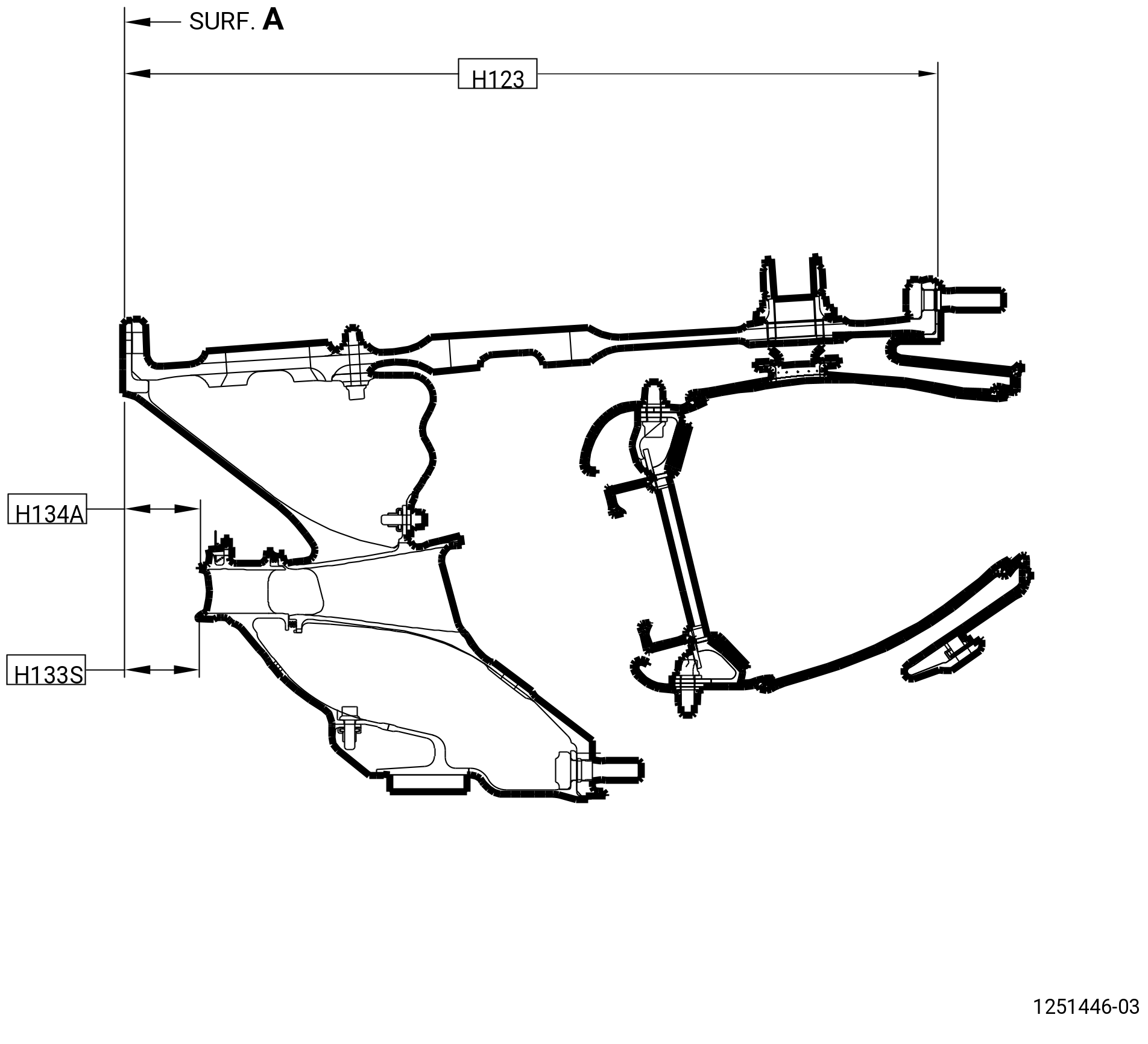
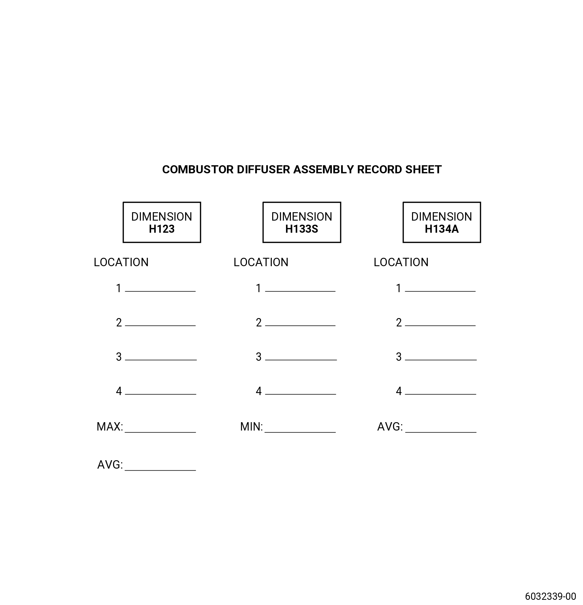
| M. | Measure H133S and H134A as follows. Refer to Figure 1015. |
| (1) | Measure dimension H133S at the 12:00 o'clock, 3:00 o'clock, 6:00 o'clock, and 9:00 o'clock positions and record. |
| (a) | Minimum reading (1.417-1.447 inches (35.99-36.75 mm)): _________. |
| (2) | Measure dimension H134A at the 12:00 o'clock, 3:00 o'clock, 6:00 o'clock, and 9:00 o'clock positions and record the average reading. |
| (a) | Average reading __________. (1.435-1.465 inches (36.45-37.21 mm)). |
| Subtask 72-41-00-220-017 |
| N. | Measure dimension H123 as follows. Refer to Figure 1015. |
| (1) | Measure dimension H123 at the 12:00 o'clock, 3:00 o'clock, 6:00 o'clock, and 9:00 o'clock positions. |
| (a) | Record the maximum reading. |
| (b) | H123 limits, 15.531-15.547 inches (394.49-394.89 mm). |
| (c) | Record the average of the four readings, H123AVG. |
| Subtask 72-41-00-440-027 |
| O. | Install the igniter plug adapters (01-050 , 74-21-20) (SIN 66201) in the igniter pads of the combustor case (01-079) (SIN 12001) or (01-080) (SIN 12001) at the 8:45 o'clock and 10:00 o'clock positions, ALF. Refer to Figure 1016 and do as follows: |
| CAUTION: |
|
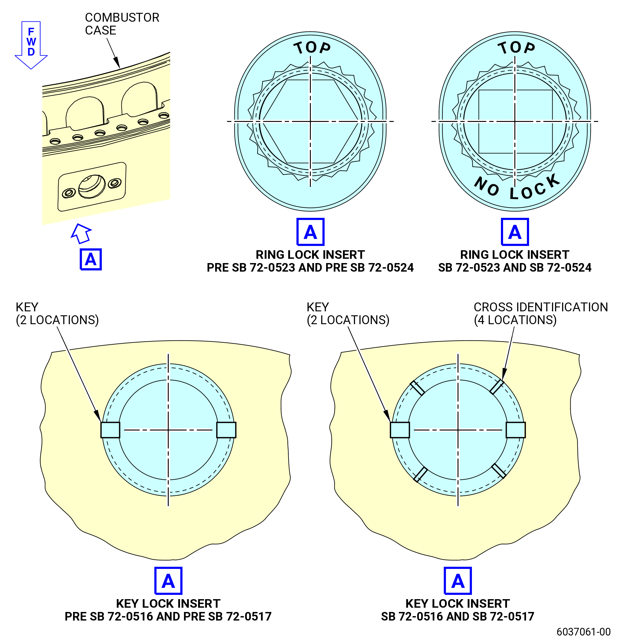
| (1) | Examine CDN case compliance to SB 72-0516 , SB 72-0517, SB 72-0523, SB 72-0524, and SB 72-0532. Refer to Figure 1017 and as follows: |
| (a) | SB 72-0516, SB 72-0517, SB 72-0523, and SB 72-0524 inserts have unique marking located at top surface. Refer to Figure 1017. |
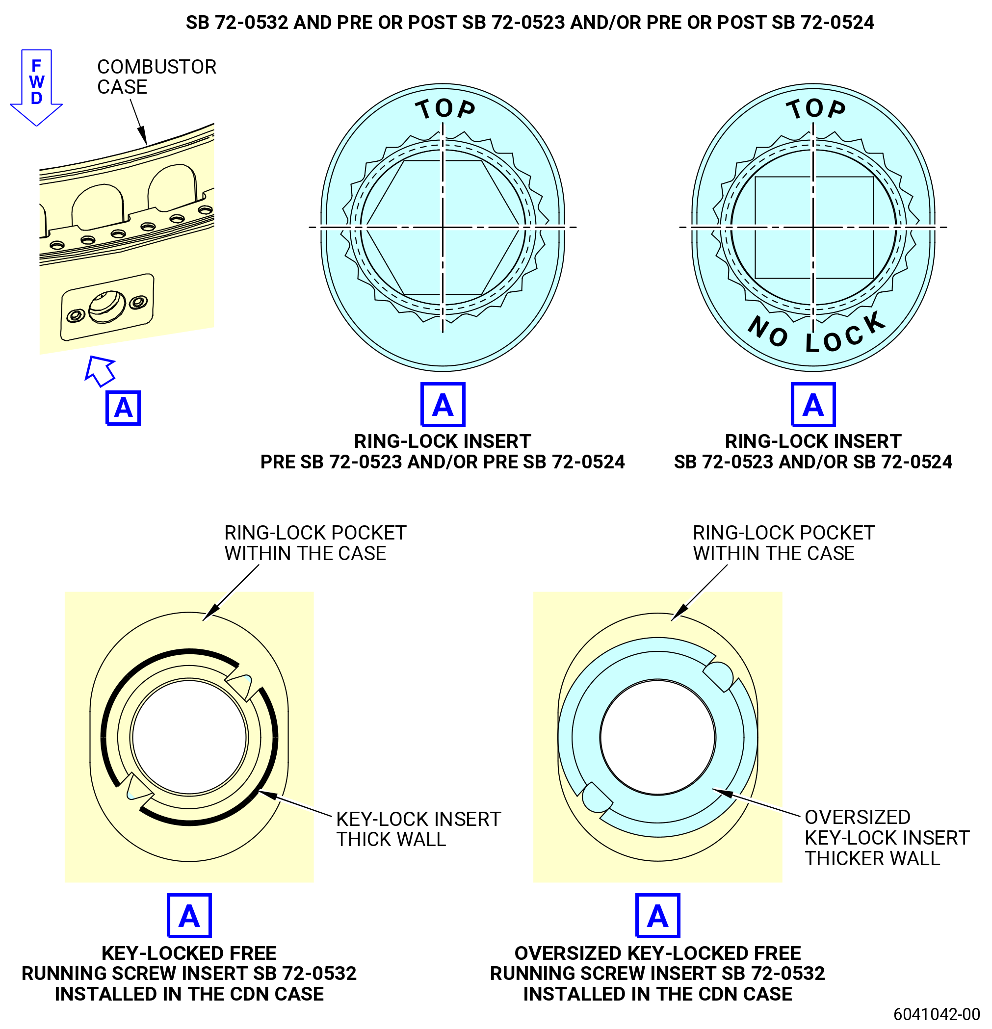
| (b) | SB 72-0532 key-locked free running screw insert and/or oversized key-locked free running screw insert can be installed in quantity as required to igniter adapter pads. SB 72-0532 is applicable to all CDN case insert configurations. |
| (c) | In effect, SB 72-0532 and PRE SB 72-0366 and/or SB 72-0523 and/or SB 72-0524 configuration results in intermixed insert configuration with key-locked free running screw insert (SB 72-0532) and/or oversized key-locked free running screw insert (SB 72-0532) in quantity as required and all remaining ring-lock inserts (PRE SB 72-0366) and/or free running ring locked inserts (SB 72-0523 and/or SB 72-0524) installed. The new SB 72-0532 screw inserts have thicker wall comparing to PRE SB 72-0366 , SB 72-0523 and SB 72-0524 inserts. Refer to Figure 1017. |
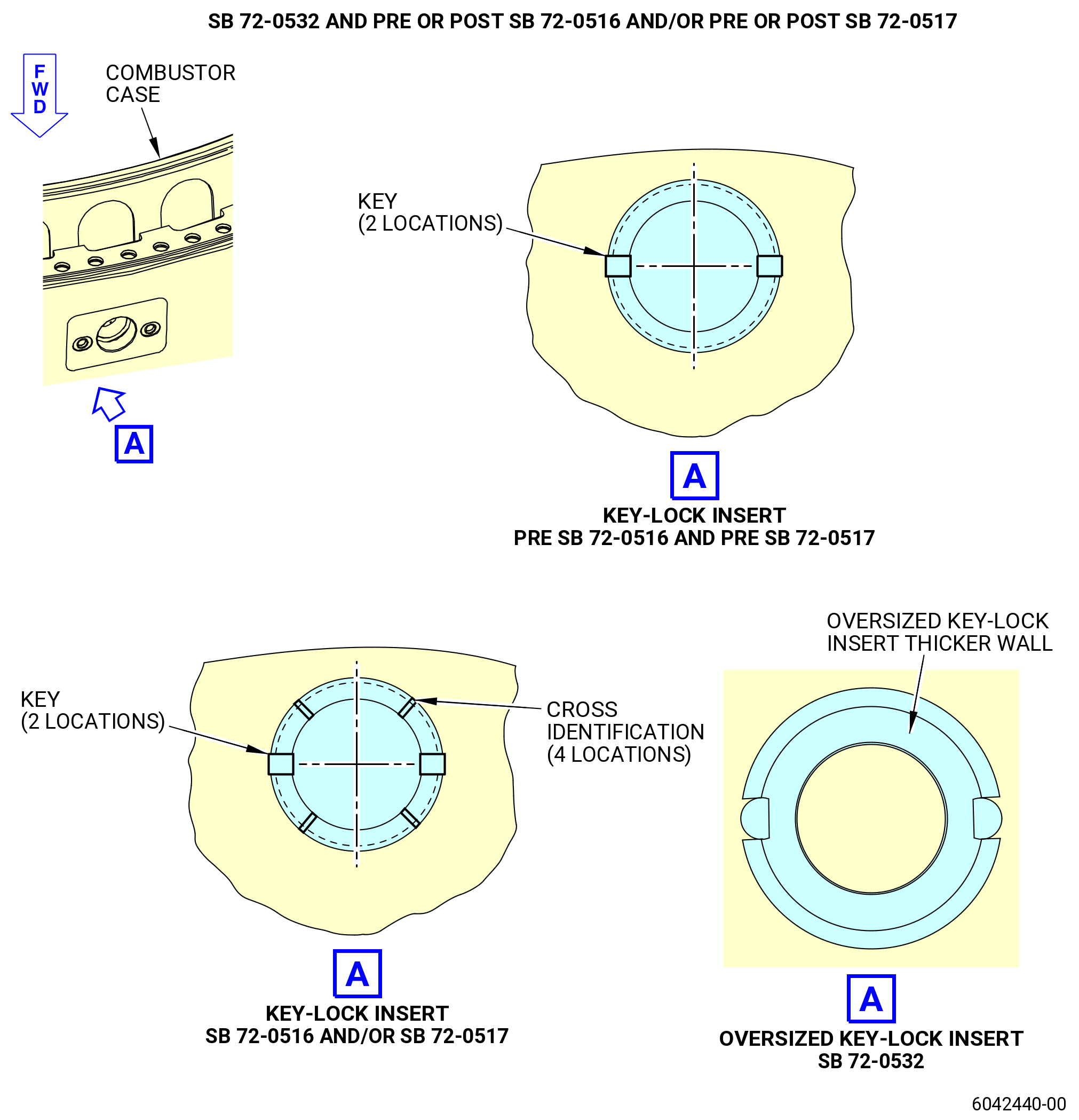
| (d) | SB 72-0532 and POST SB 72-0366 and/or POST SB 72-0516 and/or POST SB 72-0517 configuration results in intermixed insert configuration with oversized key-locked free running screw insert (SB 72-0532) in quantity as required and all remaining key-locked screw inserts (SB 72-0366) and/or key-locked free running screw inserts (SB 72-0516 and/or SB 72-0517). The new oversized key-locked free running screw insert has thicker wall comparing to SB 72-0366, SB 72-0516 and SB 72-0517 inserts. Refer to Figure 1017. |
| (e) | Make sure that SB 72-0516, SB 72-0517, SB 72-0523, SB 72-0524, and SB 72-0532 inserts are being assembled with bolts (01-040 , 74-21-20) (SIN 66220) and safety cable/wire. |
| WARNING: |
|
| CAUTION: |
|
| (2) | Apply C02-097 lubricant or optionally C02-058 lubricant to only the threads and friction surfaces of the bolts (01-040 , 74-21-20) (SIN 66220). |
| (3) | Install one new seal assembly (01-060 , 74-21-20) (SIN 66250) and one igniter plug adapter to the 8:45 o'clock and 10:00 o'clock positions of the combustor case with the new bolts (01-040 , 74-21-20) (SIN 66220). |
| (a) | Make sure that the inner ring is installed on the seal assembly (01-060 , 74-21-20) (SIN 66250). |
| (4) | Torque the bolts (01-040 , 74-21-20) (SIN 66220) to 135 to 140 lb in. (15.2 to 15.8 Nm). |
| (5) | One bolt at a time unseat and tighten each of the bolts that safety the igniter plug adapter (01-050 , 74-21-20) (SIN 66201) to the combustion case (01-079) (SIN 12001) or (01-080) (SIN 12001). Apply a final torque to the bolts (01-040 , 74-21-20) (SIN 66220) to 135 to 140 lb in. (15.2 to 15.8 Nm). |
| WARNING: |
|
| CAUTION: |
|
| (6) | Apply C02-097 lubricant or optionally C02-058 lubricant to the threads on the outer diameter of the igniter plug adapter and the threads on the igniter plug bushing (01-020 , 74-21-20) (SIN 66203). |
| (7) | Install one igniter plug gasket (01-030 , 74-21-20) (SIN 66270) and one igniter plug bushing (66203) to the igniter plug adapters at the 8:45 o'clock and 10:00 o'clock positions of the combustor case. |
| (8) | Tighten but do not torque the igniter plug adapter. |
| (9) | Torque the igniter plug bushings to 382-448 lb in. (43.2-50.6 N.m). |
| (10) | Torque the igniter plug bushings again to 382-448 lb in. (43.2-50.6 N.m). |
| Subtask 72-41-00-220-013 |
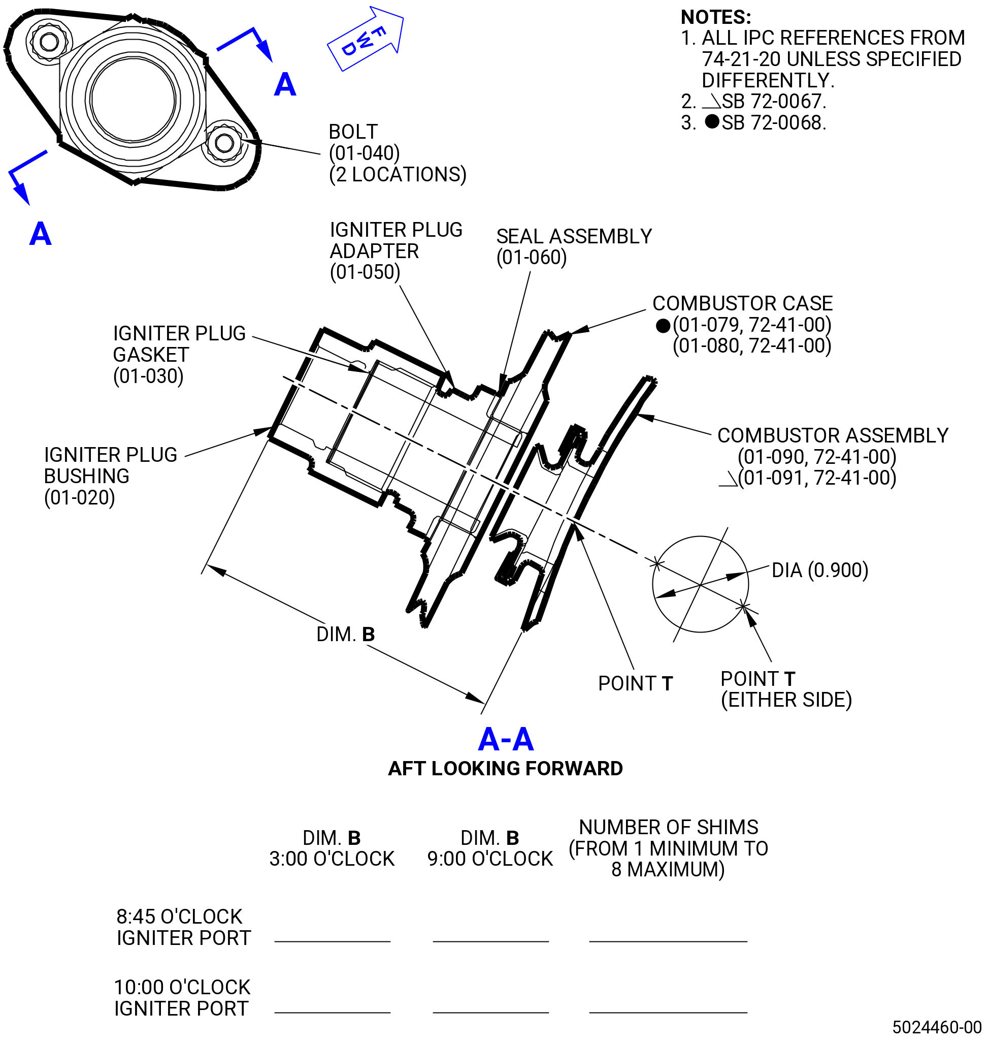
| (11) | Do an inspection of each igniter plug adapter assembly with the 11C3340 immersion depth gage as follows. Refer to Figure 1018. |
| (a) | Install the immersion depth gage into an igniter plug adapter assembly. Measure dimension B from the outboard end of the igniter plug bushing (66203) into the inside of the combustor chamber outer liner. |
| (b) | With the combustor case in a vertical position, make sure that the measurement is taken at point T, at the 3:00 o'clock position or 9:00 o'clock position of the combustor chamber outer liner. |
| (c) | The minimum distance permitted is 3.010 inches (76.45 mm) and the maximum distance permitted is 3.026 inches (76.86 mm). |
| Subtask 72-41-00-440-029 |
| (12) | If necessary, correct the dimension at each port as follows. Refer to Figure 1016. |
| (a) | Remove the igniter plug bushing (66203) from the igniter plug adapter. |
| (b) | Calculate the number of additional igniter plug gaskets (01-030 , 74-21-20) (SIN 66270), based on the thickness of a single igniter plug gasket, necessary to get the correct immersion depth measurement. |
| WARNING: |
|
| CAUTION: |
|
| (c) | Apply C02-097 lubricant or optionally C02-058 lubricant to the threads on the outer diameter of the igniter plug adapter and the threads of the igniter plug bushing (01-020 , 74-21-20) (66203). |
| (d) | Install the additional calculated number of igniter plug gaskets (01-030 , 74-21-20) (SIN 66270), to a maximum of eight, and the igniter plug bushing (66203) on the igniter plug adapter. |
| (e) | Record the number of gaskets used at each of the igniter plug adapter ports. Refer to Figure 1018. |
| Subtask 72-41-00-440-170 |
| (13) | Measure dimension B again to make sure it is in limits. Refer to Subtask 72-41-00-220-013 (paragraph 3.K.(7)). |
| (a) | Record final dimension B for each igniter plug adapter port. |
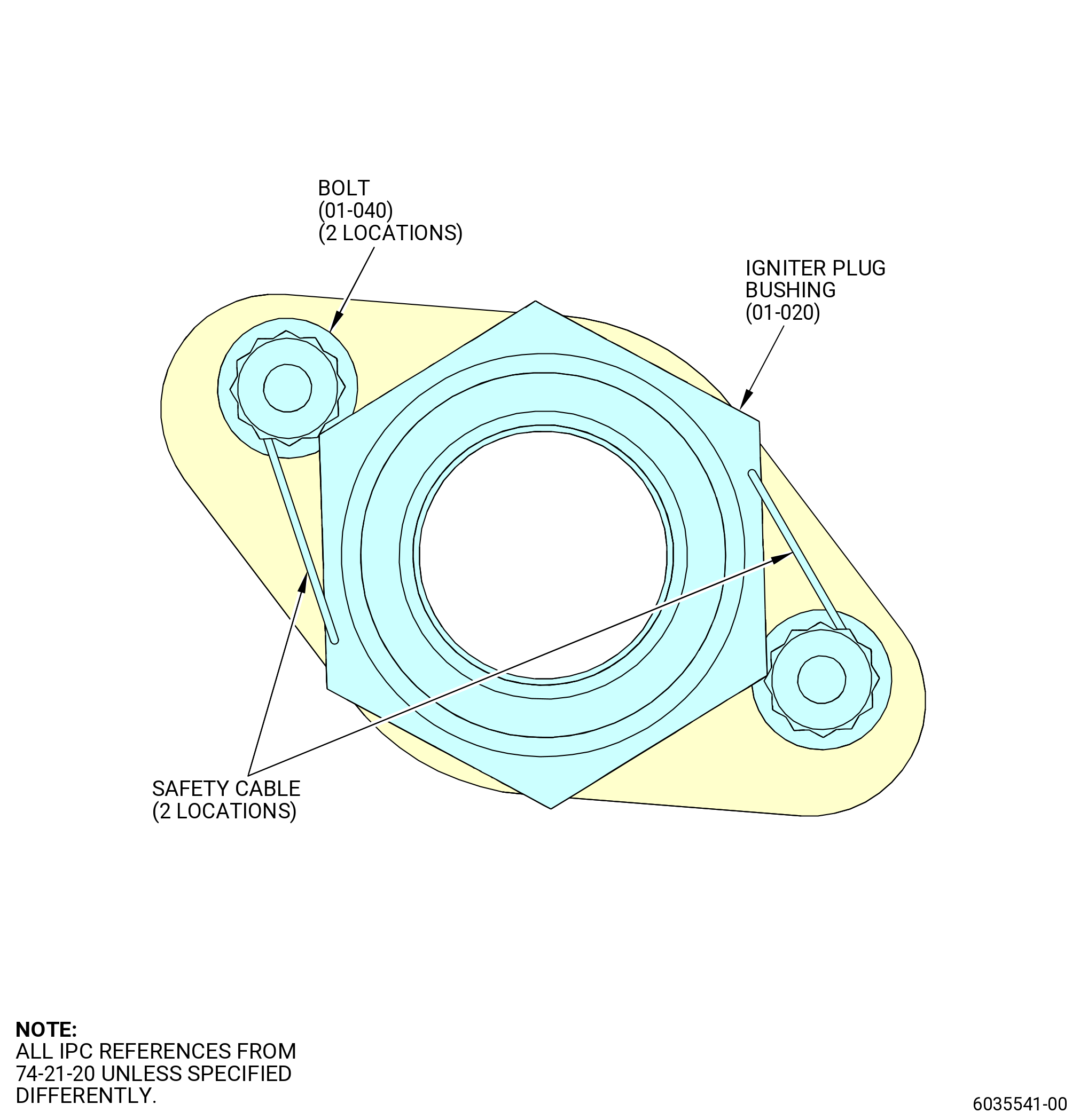
| (14) | Safety the igniter plug bushings (01-020 , 74-21-20) (SIN 66203) at the 8:45 o'clock and 10:00 o'clock positions, to the bolts (2 locations for each adapter) (01-040 , 74-21-20) (SIN 66220). Refer to Figure 1019 and do as follows: |
| (a) | Route one C10-143 safety cable assembly for each of the two bolts (01-040 , 74-41-20) (SIN 66220). Refer to TASK 70-11-00-400-001 (FASTENER RETENTION PROCEDURES). |
| Subtask 72-41-00-440-173 |
| P. | Storage or shop transportation. |
| (1) | If necessary, put the module with the 11C4432 ring support in the storage and shop transportation stand. |