| GENX-1B CLEANING,INSPECTION,AND REPAIR MANUAL | Dated: 06/05/2024 | |
| CIR 72-41-20 , REPAIR 010 | ||
| STAGE 10 OUTLET GUIDE VANE - REPAIR - HONEYCOMB PRE-GROOVE MACHINING | ||
| GENX-1B CLEANING,INSPECTION,AND REPAIR MANUAL | Dated: 06/05/2024 | |
| CIR 72-41-20 , REPAIR 010 | ||
| STAGE 10 OUTLET GUIDE VANE - REPAIR - HONEYCOMB PRE-GROOVE MACHINING | ||
| * * * FOR ALL |
| TASK 72-41-20-300-811 |
| 1 . | Honeycomb Pre-Groove Machining. |
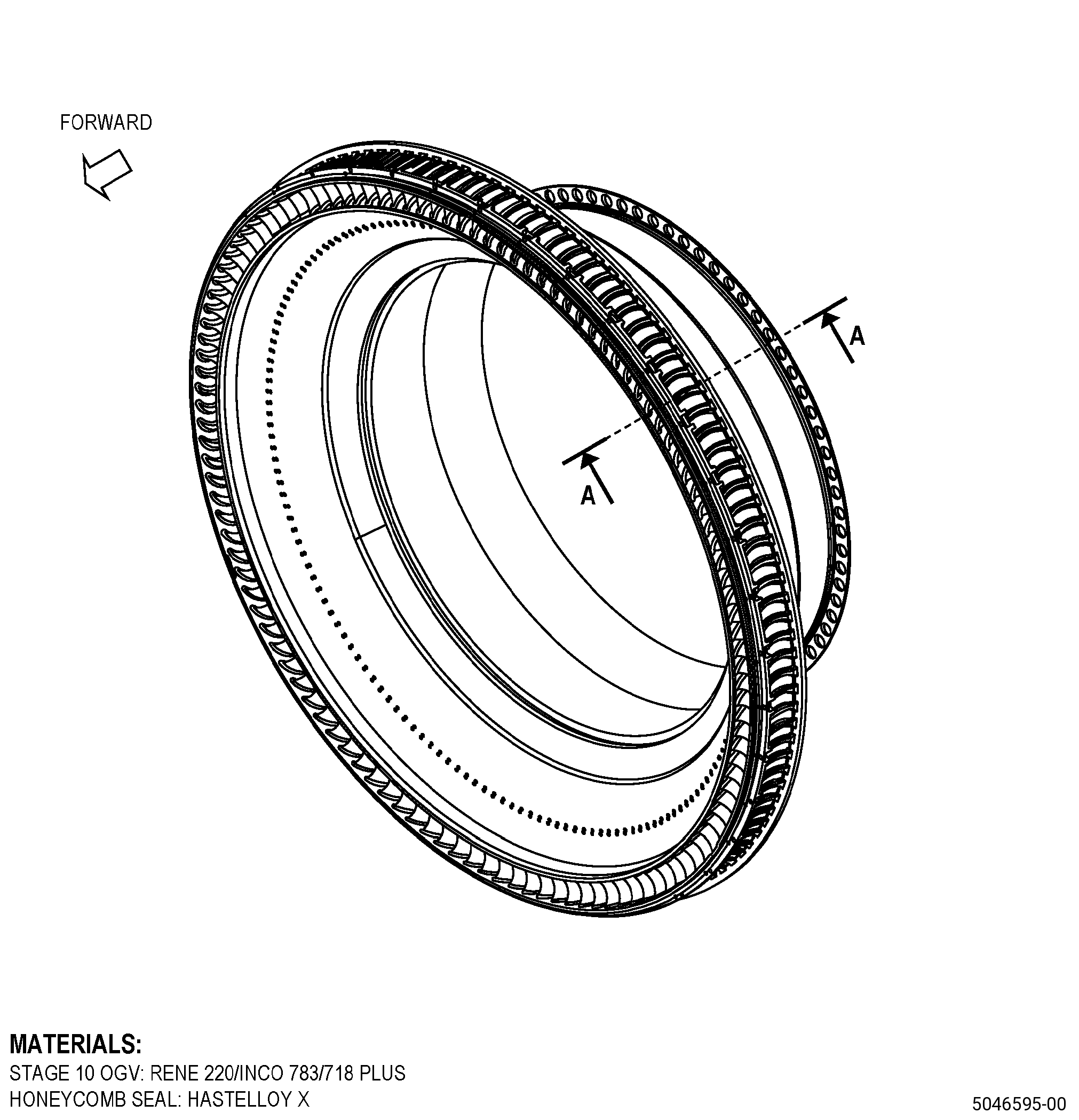
| A. | This procedure gives instructions to repair the stage 10 outlet guide vane (OGV) by pre-groove machining the honeycomb. Refer to Figure 901. |
| NOTE: |
|
| B. | There are no maximum repairable limits for this repair. |
| C. | The subsequent table gives a list of the part numbers that are applicable to this repair. All part numbers are applicable to all paragraphs unless specified differently. |
|
||||||||||||||||||||||||||||||||||||||||||||||||||||||||||||||
| D. | Proprietary/Complex Process Statement. |
| (1) | None. |
| 2 . | Tools, Equipment, and Materials. |
| NOTE: |
|
| A. | Tools and Equipment. |
| (1) | Special Tools. None. |
| (2) | Standard Tools and Equipment. None. |
| (3) | Locally Manufactured Tools. None. |
| B. | Consumable Materials. |
|
| C. | Referenced Procedures. |
|
| D. | Expendable Parts. None. |
| E. | SPD Information. |
| (1) | Locally Manufactured SPD. None. |
| F. | Special Solutions. None. |
| G. | Test Specimens. None. |
| 3 . | Dimensional Information. |
| Subtask 72-41-20-220-102 |
| A. | Refer to Figure 901 for specified dimensions and locations. |
| NOTE: |
|
| NOTE: |
|
| 4 . | Setup Information. |
| Subtask 72-41-20-350-082 |
| A. | Set-up the OGV for machining/grinding as follows: |
| Subtask 72-41-20-930-006 |
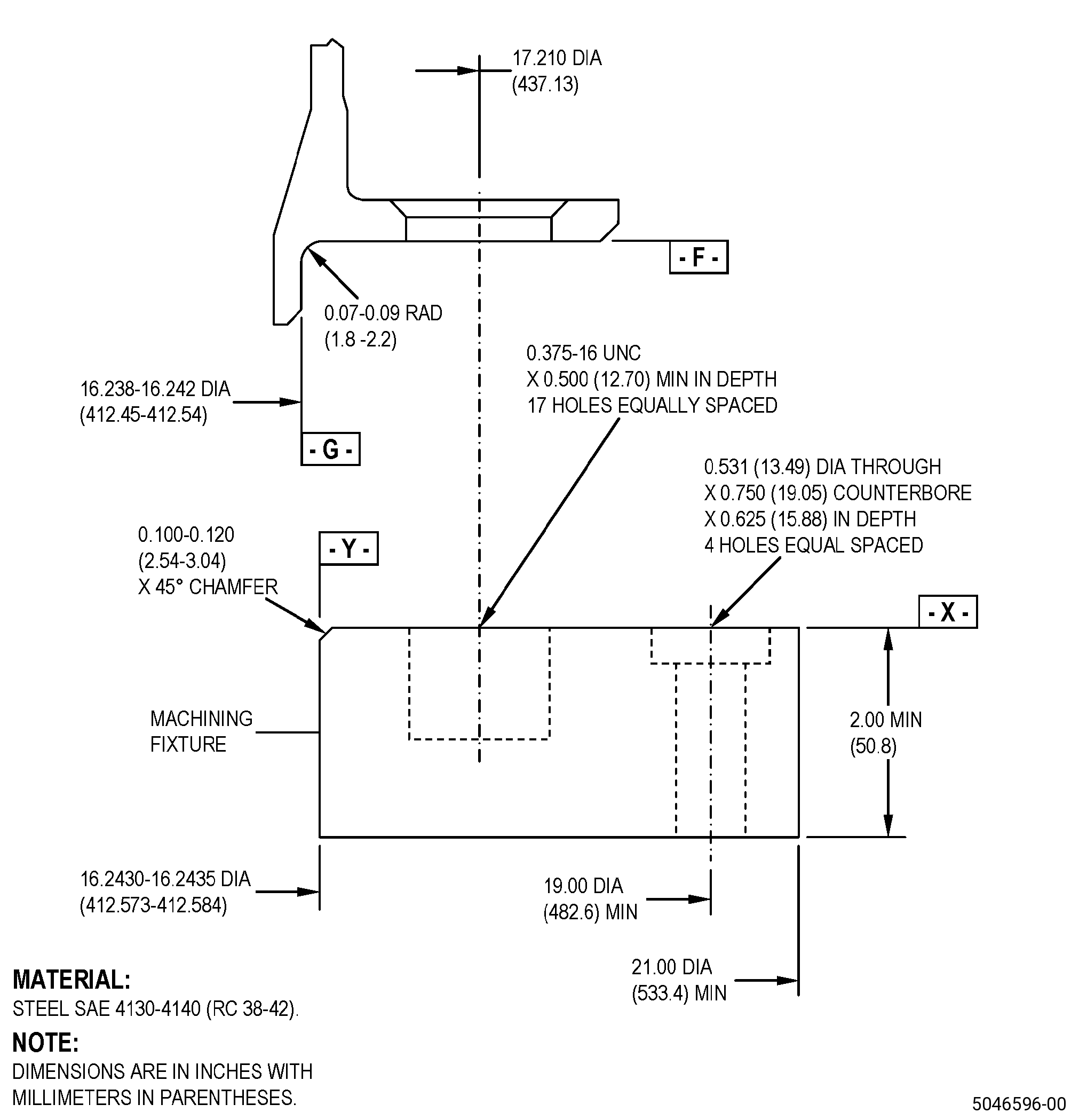
| (1) | If necessary, make the machining fixture. Refer to Figure 902. |
| Subtask 72-41-20-350-083 |
| (2) | Install the machining fixture on the machining table as follows: |
| (a) | Adjust the position of the machining fixture to get the runout of surface X to 0.001 inch (0.02 mm) FIR or less as follows: |
| 1 | If necessary, put C10-155 shims between the machining fixture and the machining table to get the necessary runout. |
| (b) | If necessary, adjust the position of the machining fixture to make sure that the runout of diameter Y is 0.001 inch (0.02 mm) FIR or less. |
| (c) | Use four 0.500-13 UNC socket-head capscrews to hold the machining fixture to the machining table and as follows: |
| 1 | Make sure that the runouts of surface X and diameter Y agree with the requirements specified in Subtask 72-41-20-350-083 (paragraph 4.A.(2)(a)) and Subtask 72-41-20-350-083 (paragraph 4.A.(2)(b)). |
| (3) | Install the OGV onto the machining fixture as follows: |
| NOTE: |
|
| (a) | Put the OGV onto the machining fixture and align the boltholes in the flange with the 17 threaded holes in the machining fixture. |
| (b) | Attach the OGV to the machining fixture with seventeen 0.375-16 UNC bolts or screws. |
| (4) | Make sure that you install the OGV flat on the machining fixture as follows: |
| (a) | The maximum permitted clearance between surface X of the machining fixture and surface F of the OGV is 0.002 inch (0.05 mm). |
| 5 . | Procedure. |
| Subtask 72-41-20-350-085 |
| A. | Remove the three cover plates from the OGV. Refer to TASK 72-41-20-300-802 (72-41-20, REPAIR 003). |
| Subtask 72-41-20-320-018 |
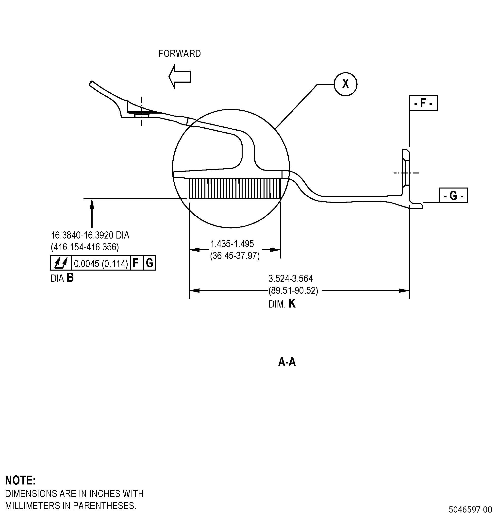
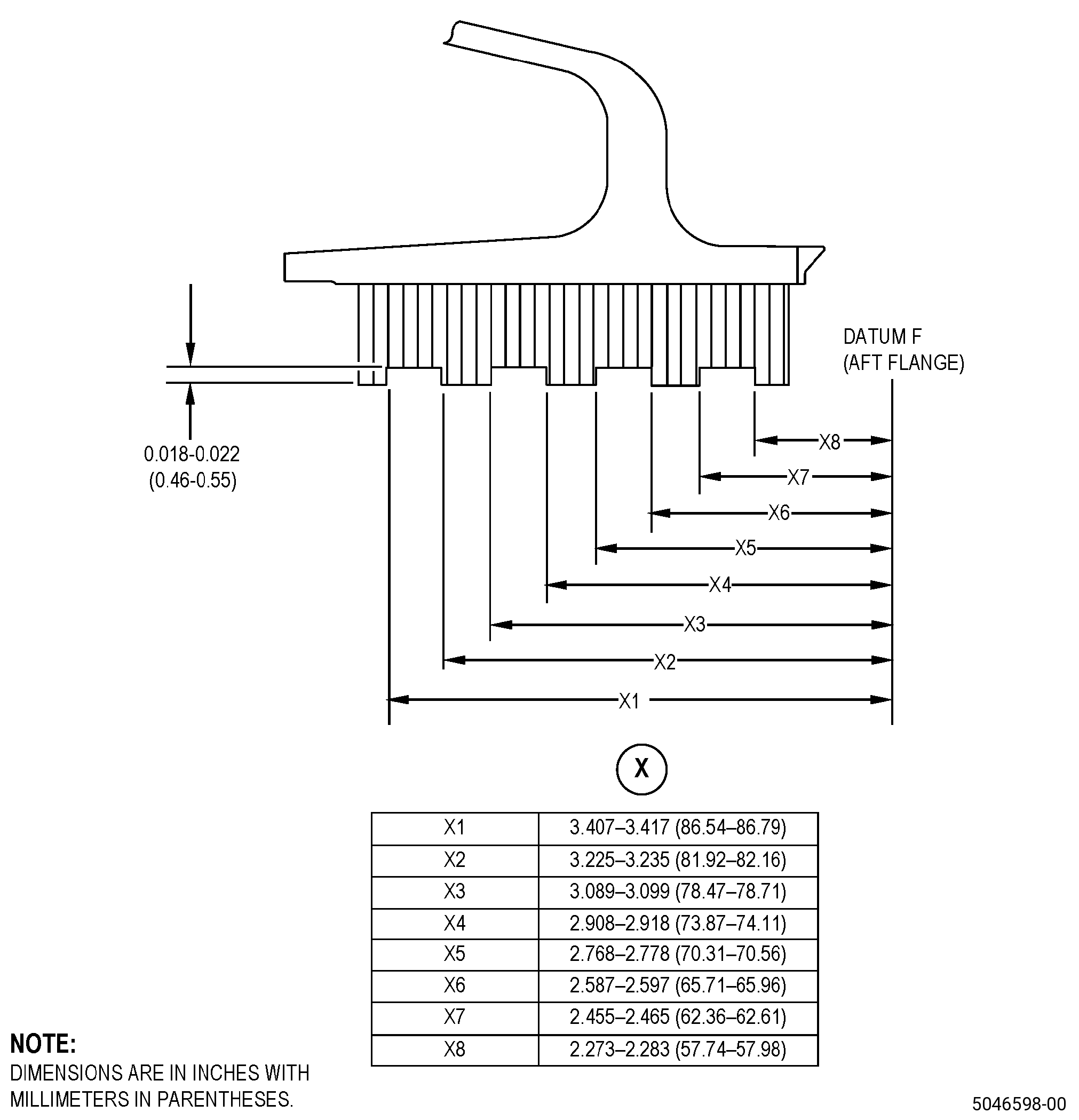
| B. | Alternative Procedure Available. Machine the honeycomb seal pre-groove on diameter B. Refer to TASK 70-00-03-800-004 (MACHINING DATA), Figure 901Figure 903, and do as follows: |
| NOTE: |
|
| Subtask 72-41-20-350-084 |
| (1) | Set-up the OGV for machining. Refer to Subtask 72-41-20-350-082 (paragraph 4.A.). |
| Subtask 72-41-20-320-019 |
| (2) | Machine the honeycomb seal diameter B. Refer to TASK 70-31-05-220-001 (ENGINE PART SURFACE INTEGRITY ACCEPTABILITY LIMITS FOR NONTRADITIONAL MACHINED SURFACES), and as follows: |
| (a) | The average recast layer permitted on the honeycomb seal surfaces is 0.002 inch (0.05 mm) or less. |
| (b) | The maximum recast layer permitted on the honeycomb seal surface is 0.004 inch (0.10 mm). |
| (c) | Micro-cracks are permitted in the recast layer only. |
| (d) | The maximum intergranular attack permitted on the honeycomb surface is 0.0015 inch (0.038 mm) or less. |
| (e) | Surface finish requirements do not apply to the machined honeycomb seal surfaces. |
| (f) | Metal particles into the honeycomb cells are not permitted, unless it is as follows: |
| 1 | Material that is not more than 0.002 inch (0.05 mm) built-up and is as follows: |
| a | Perpendicular to the cell wall. |
| b | In the top 25 percent of the finished machined cell height. |
| (g) | Metal particles that are on the surface adjacent to the honeycomb seal are not permitted. |
| Subtask 72-41-20-220-104 |
| (3) | Do a dimensional inspection of the honeycomb diameters and honeycomb runout while the OGV is in the fixture. |
| (4) | Remove the OGV seal from the machining fixture. |
| Subtask 72-41-20-320-020 |
| B.A. | Alternative Procedure. Grind the honeycomb seal pre-groove on diameter B. Refer to TASK 70-00-03-800-004 (MACHINING DATA), Figure 901, Figure 903, and do as follows: |
| (1) | Set-up the OGV for grinding. Refer to Subtask 72-41-20-350-082 (paragraph 4.A.). |
| Subtask 72-41-20-220-105 |
| (2) | Do a dimensional inspection of the honeycomb diameters and honeycomb runout while the OGV is in the fixture. |
| (3) | Remove the OGV seal from the machining fixture. |
| Subtask 72-41-20-220-106 |
| C. | Do a visual inspection of the honeycomb seal for cells filled with remaining braze material as follows: |
| (1) | Filled cells are not permitted unless they agree with the conditions that follow: |
| (a) | All cells agree with a pin that measures 0.010 inch (0.25 mm) in diameter and 0.250 inch (6.35 mm) in depth. |
| (b) | Filled cells are permitted in the forward end partial cell area or aft end partial cell area. |
| (c) | If necessary, repair filled cells by EDM or with a jeweler's drill to make them agree with the limits as follows: |
| 1 | No more than two percent of the honeycomb cells are repaired in a circumferential row. |
| 2 | Repaired cells must agree with a pin that measures 0.010 inch (0.25 mm) in diameter and 0.250 inch (6.35 mm) in depth. |
| Subtask 72-41-20-440-007 |
| D. | Install the three cover plates onto the OGV. Refer to TASK 72-41-20-300-802 (72-41-20, REPAIR 003). |
| Subtask 72-41-20-160-013 |
| E. | If necessary, clean the OGV. Refer to TASK 72-41-20-100-801 (72-41-20, CLEANING 001). |