| GENX-1B CLEANING,INSPECTION,AND REPAIR MANUAL | Dated: 06/05/2024 | |
| CIR 72-41-20 , REPAIR 003 | ||
| STAGE 10 OUTLET GUIDE VANE - REPAIR - REPLACEMENT OF THE COVER PLATES AND SELF-LOCKING NUT ASSEMBLY | ||
| GENX-1B CLEANING,INSPECTION,AND REPAIR MANUAL | Dated: 06/05/2024 | |
| CIR 72-41-20 , REPAIR 003 | ||
| STAGE 10 OUTLET GUIDE VANE - REPAIR - REPLACEMENT OF THE COVER PLATES AND SELF-LOCKING NUT ASSEMBLY | ||
| * * * FOR ALL |
| TASK 72-41-20-300-802 |
| 1 . | Repair for the Stage 10 Outlet Guide Vane. |
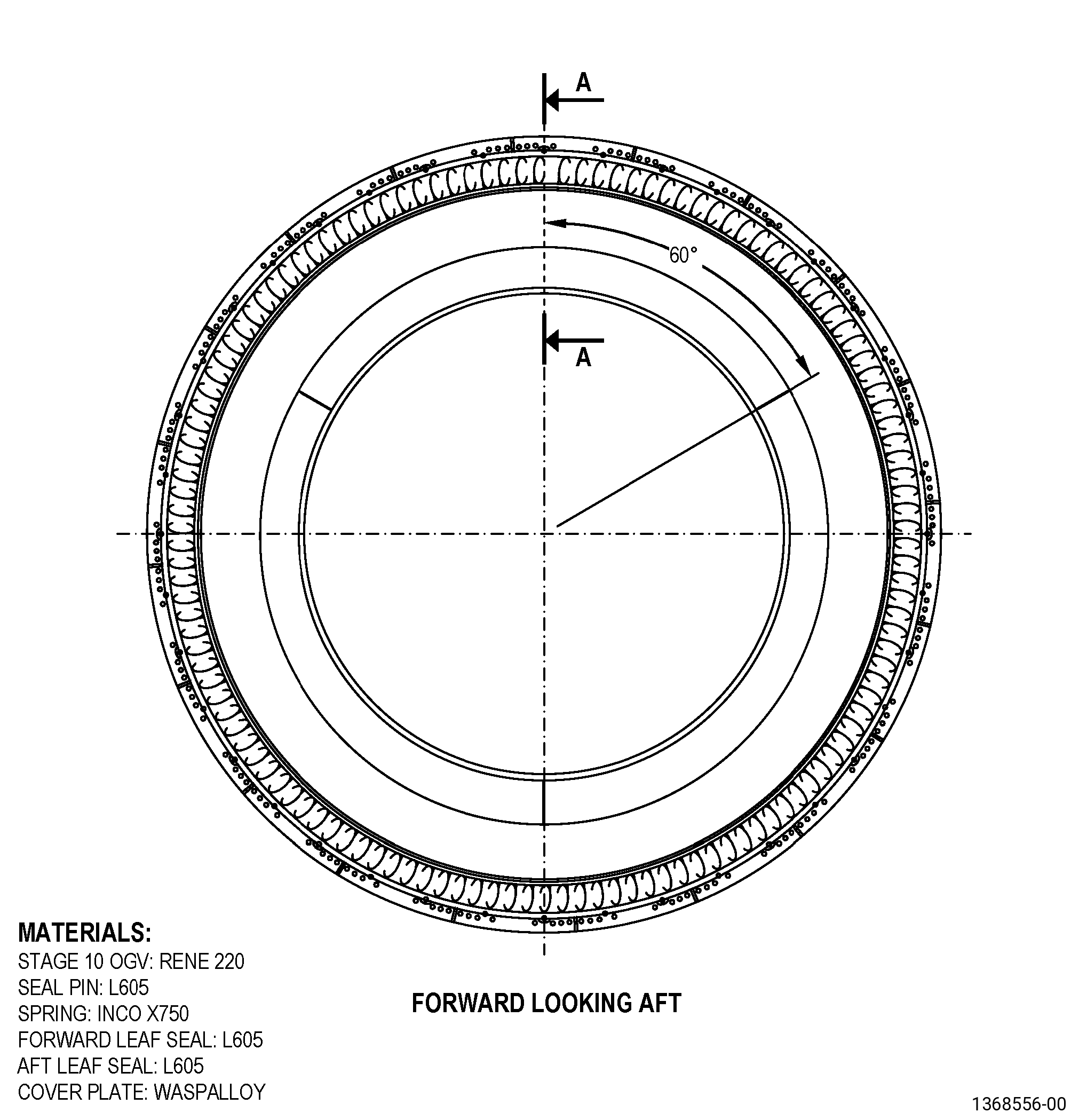
| A. | This procedure gives instructions to repair the stage 10 outlet guide vane (OGV) by replacing the self-locking nut assembly (self-locking nuts) and the cover plates. Refer to Figure 901. |
| B. | The following maximum repairable limits apply to this repair: |
| NOTE: |
|
| (4) | Visual Inspection. |
| (j) | Do an inspection of the cover plate self-locking nut for: |
| NOTE: |
|
| 1 | Damaged self-locking nut or partial seized bolts: |
| Maximum repairable limit: |
|
| C. | The subsequent table gives a list of the part numbers that are applicable to this repair. All part numbers are applicable to all paragraphs unless specified differently. |
|
||||||||||||||||||||||||||||||||||||||||||||||||||||||||||||||
| D. | Proprietary/Complex Process Statement. |
| (1) | None. |
| 2 . | Tools, Equipment, and Materials. |
| NOTE: |
|
| A. | Tools and Equipment. |
| (1) | Special Tools. None. |
| (2) | Standard Tools and Equipment. |
|
| (3) | Locally Manufactured Tools. None. |
| B. | Consumable Materials. |
|
| C. | Referenced Procedures. |
| D. | Expendable Parts. |
|
| E. | SPD Information. |
|
| (1) | Locally Manufactured SPD. None. |
| F. | Special Solutions. None. |
| G. | Test Specimens. None. |
| 3 . | Dimensional Information. |
| Subtask 72-41-20-220-037 |
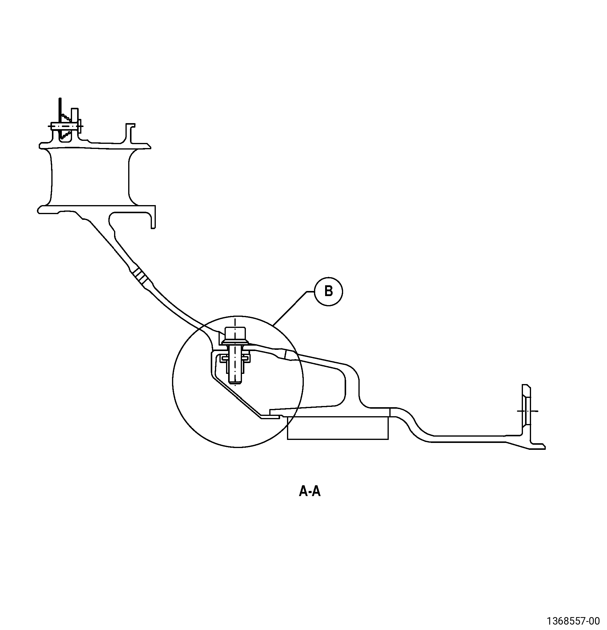
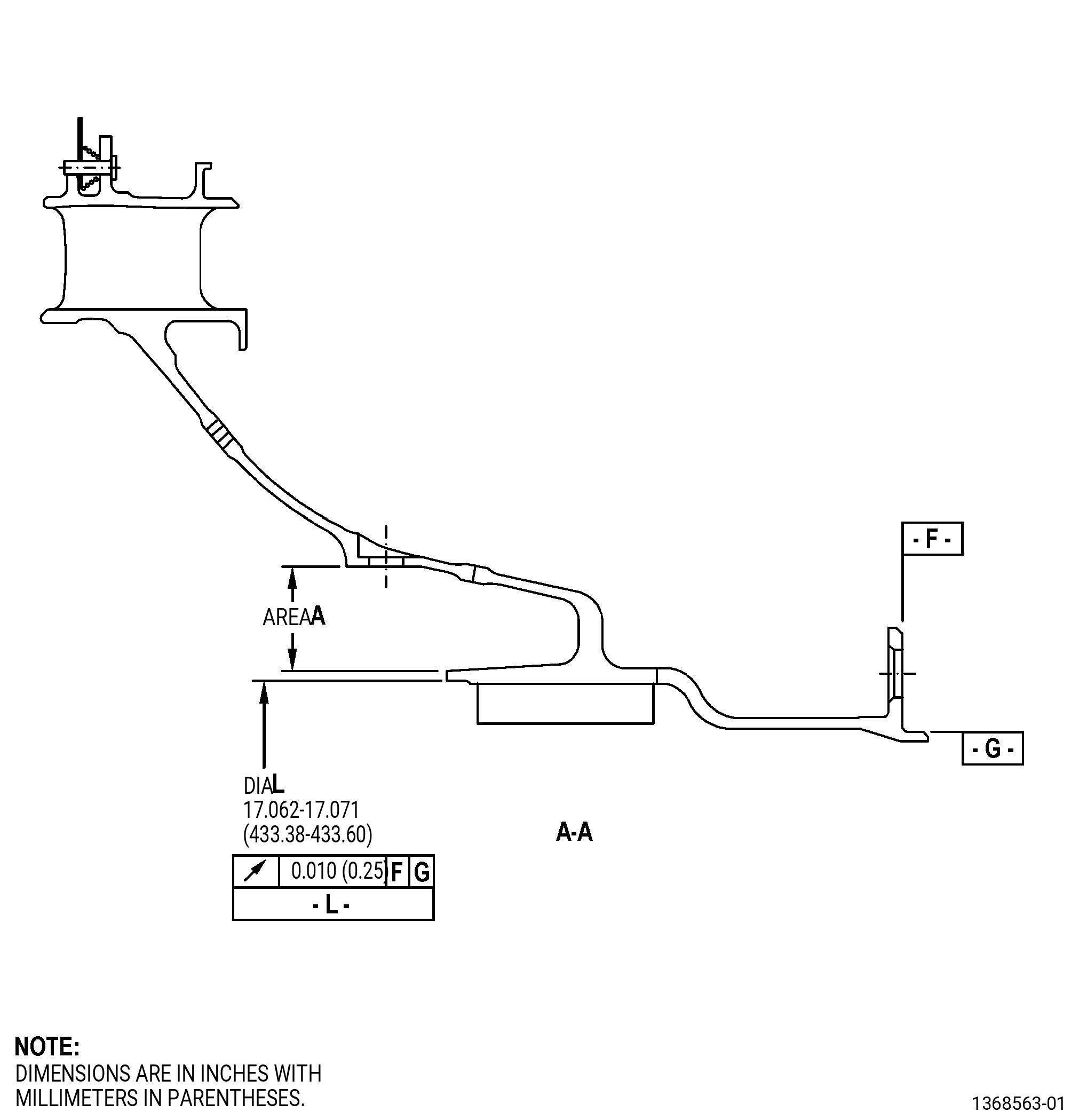
| A. | Refer to Figure 901 for specified dimensions and locations. |
| NOTE: |
|
| NOTE: |
|
| 4 . | Setup Information. |
| None. |
| 5 . | Procedure. |
| Subtask 72-41-20-160-002 |
| A. | If necessary, clean the stage 10 OGV. Refer to TASK 72-41-20-100-801 (72-41-20, CLEANING 001). |
| Subtask 72-41-20-350-002 |
| B. | Remove the three cover plates from the stage 10 OGV. Refer to Figure 901 and as follows: |
| (1) | Make sure that you tag the location where you removed the cover plates. |
| (2) | If necessary, use slave bolts to help disassemble the cover plates from the stage 10 OGV as follows: |
| (a) | Turn the slave bolts equally spaced into the inserts of the cover plate as necessary. |
| (b) | Keep a clearance of approximately 0.250 inch (6.35 mm) between the head of the slave bolt and the stage 10 OGV. |
| (c) | Tap the heads of the slave bolts with a mallet until the cover plates are disconnected from the stage 10 OGV. |
| (d) | Remove the slave bolts and the cover plates from the stage 10 OGV. |
| Subtask 72-41-20-230-016 |
| C. | Do an inspection of the stage 10 OGV area A and the cover plates. Refer to TASK 70-32-00-200-002 (INDIRECT INSPECTION METHODS), TASK 70-32-03-230-002 (SPOT-FLUORESCENT-PENETRANT INSPECTION), Figure 902, and as follows: |
| (1) | Use Class A penetrant. |
| (2) | Refer to TASK 72-41-20-200-801 (72-41-20, INSPECTION 001), paragraph 3.A., for the acceptability limits. |
| Subtask 72-41-20-220-045 |
| D. | Do a dimensional inspection of the stage 10 OGV diameter L. Refer to Figure 902 and as follows: |
| (1) | If the stage 10 OGV diameter L does not agree with the necessary dimensional limits, you cannot repair the stage 10 OGV with this procedure. |
| Subtask 72-41-20-220-040 |
| E. | Do an inspection of the cover plates of the stage 10 OGV for worn or damaged self-locking nuts as follows: |
| (1) | If the cover plate has worn or damaged self-locking nuts or partial seized bolts, go to Subtask 72-41-20-390-001 (paragraph 5.F.). |
| (2) | If the cover plate does not have worn or damaged self-locking nuts or partial seized bolts, go to Subtask 72-41-20-440-004 (paragraph 5.O.). |
| Subtask 72-41-20-390-001 |
| F. | Remove the rivets from the damaged cover plates from the stage 10 OGV. Refer to TASK 70-13-00-390-001 (RIVETED JOINTS), Figure 901, and as follows: |
| (1) | Discard the removed cover plate rivets. |
| Subtask 72-41-20-350-004 |
| G. | Remove and discard the damaged self-locking nuts from the stage 10 OGV. |
| Subtask 72-41-20-350-005 |
| H. | If necessary, blend the cover plate repair area of the stage 10 OGV. Refer to TASK 70-42-00-350-002 (BLENDING AND REMOVAL OF HIGH METAL PROCEDURES) and as follows: |
| (1) | Blend the cover plate repair area of the stage 10 OGV to remove high metal. |
| Subtask 72-41-20-220-039 |
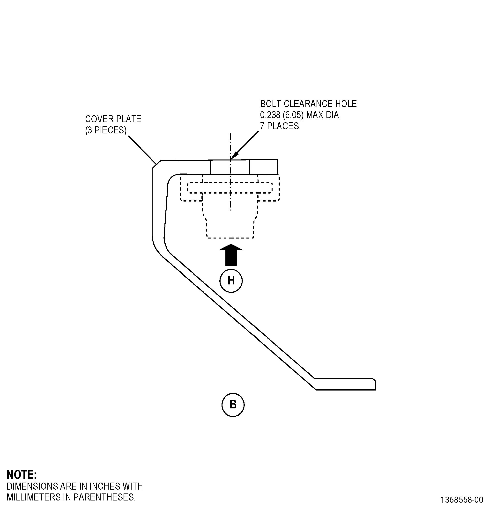
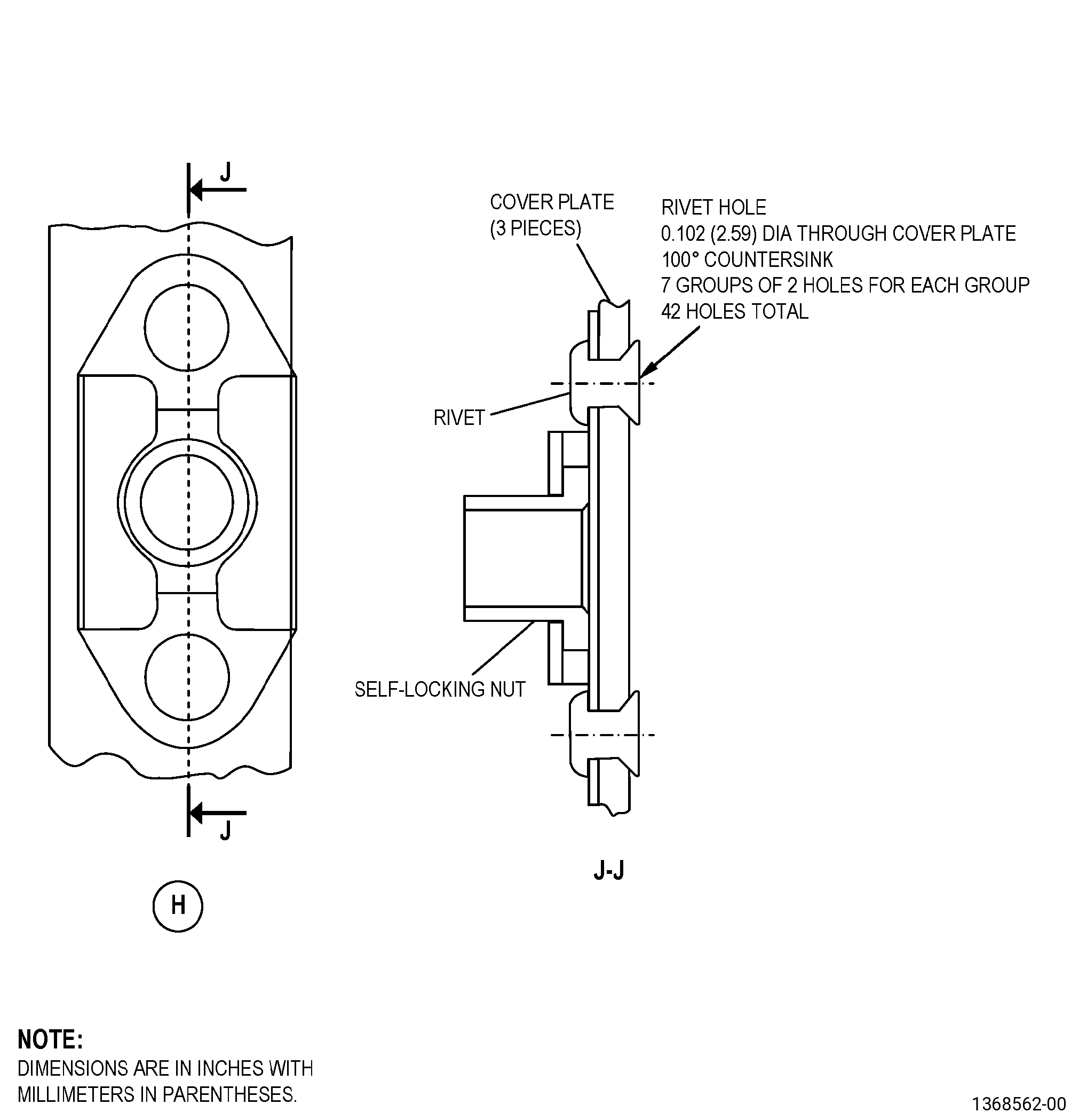
| I. | Do a dimensional inspection of the drilled out rivet holes and the bolt clearance hole in the cover plates of the stage 10 OGV. Refer to Figure 901 and as follows: |
| (1) | If the rivet holes on the cover plate are more than 0.106 inch (2.69 mm) in diameter, replace the cover plate with a SPD cover plate (01-168 , 72-41-00), and go to Subtask 72-41-20-390-002 (paragraph 5.M.). |
| NOTE: |
|
| (2) | If the bolt clearance hole on the cover plate is more than 0.238 inch (6.05 mm) in diameter, replace the cover plate with a SPD cover plate (01-168 , 72-41-00), and go to Subtask 72-41-20-390-002 (paragraph 5.M.). |
| Subtask 72-41-20-110-004 |
| J. | Etch the cover plate repair area of the stage 10 OGV. Refer to TASK 70-24-00-110-033 (ETCHING PROCEDURES FOR FLUORESCENT-PENETRANT INSPECTION), TASK 70-24-01-110-034 (SWAB ETCHING PROCEDURE), and as follows: |
| (1) | Use class C etchant. |
| Subtask 72-41-20-230-002 |
| K. | Do an inspection of the cover plate repair area of the stage 10 OGV. Refer to TASK 70-32-00-200-002 (INDIRECT INSPECTION METHODS), TASK 70-32-03-230-002 (SPOT-FLUORESCENT-PENETRANT INSPECTION), and as follows: |
| (1) | Use Class A penetrant. |
| (2) | Refer to TASK 72-41-20-200-801 (72-41-20, INSPECTION 001), paragraph 3.A., for the acceptability limits. |
| Subtask 72-41-20-110-005 |
| L. | Clean the cover plate of the stage 10 OGV. Refer to TASK 70-21-00-110-051 (CHEMICAL CLEANING) and TASK 70-21-03-160-001 (CLEANING METHOD NO. 3 - STEAM CLEANING). |
| Subtask 72-41-20-390-002 |
| M. | Install the SPD self-locking nuts and rivets on the cover plate of the stage 10 OGV. Refer to Figure 901, paragraph 2.E., SPD Information, and as follows: |
| (1) | Install the rivets. Refer to TASK 70-13-00-390-001 (RIVETED JOINTS) and TASK 70-13-01-390-002 (ACCEPTABILITY LIMITS FOR FORMED RIVETS). |
| (2) | Use the squeeze driving to give each solid rivet head its shape. |
| Subtask 72-41-20-390-003 |
| N. | Do an inspection of the installed self-locking nuts and rivets on the cover plate of the stage 10 OGV. Refer to TASK 70-13-00-390-001 (RIVETED JOINTS), TASK 70-13-01-390-002 (ACCEPTABILITY LIMITS FOR FORMED RIVETS), and as follows: |
| Subtask 72-41-20-300-003 |
| (1) | If the rivets (P/N AN123480), do not agree with the limits, do Subtask 72-41-20-220-040 (paragraph 5.E.) thru Subtask 72-41-20-390-003 (paragraph 5.N.) again. |
| (2) | If the self-locking nut (P/N J1410P03), is loose, do Subtask 72-41-20-220-040 (paragraph 5.E.) thru Subtask 72-41-20-390-003 (paragraph 5.N.) again. |
| (3) | If the floating nut in the self-locking nut (P/N J1410P03), does not agree with a minimum radial float of 0.02 inch (0.5 mm) with respect to the bolt clearance hole, refer to Figure 901 and do Subtask 72-41-20-350-002 (paragraph 5.B.) thru Subtask 72-41-20-390-003 (paragraph 5.N.) again. |
| Subtask 72-41-20-440-004 |
| O. | Install the three cover plates that you removed from the stage 10 OGV. Refer to Figure 901 and as follows: |
| (1) | Find the identification for the location of the cover plates to see where to assemble them again. Refer to Subtask 72-41-20-350-002 (paragraph 5.B.(1)). |
| WARNING: |
|
| (2) | Apply C02-058 thread lubricating compound to the bolt threads and bearing (friction) surfaces before installation. Bolts previously removed can be used for installation. |
| (3) | Assemble the three cover plates and install the 21 bolts as follows: |
| (a) | Use your hand and tighten the bolts. Do not torque the bolts. |
| (4) | Torque all the bolts in one direction to 30-40 lb in. (3.4-4.5 N.m). |
| Subtask 72-41-20-220-042 |
| P. | Do a dimensional inspection of the stage 10 OGV. Refer to TASK 72-41-20-200-801 (72-41-20, INSPECTION 001). |