| GENX-1B CLEANING,INSPECTION,AND REPAIR MANUAL | Dated: 05/10/2024 | |
| CIR 72-41-20 , INSPECTION 001 | ||
| STAGE 10 OUTLET GUIDE VANE - INSPECTION | ||
| GENX-1B CLEANING,INSPECTION,AND REPAIR MANUAL | Dated: 05/10/2024 | |
| CIR 72-41-20 , INSPECTION 001 | ||
| STAGE 10 OUTLET GUIDE VANE - INSPECTION | ||
| * * * FOR ALL |
| TASK 72-41-20-200-801 |
| 1 . | General. |
| A. | This procedure gives instructions to do an inspection of the stage 10 outlet guide vane (stage 10 OGV): |
| • |
|
| • |
|
| • |
|
| • |
|
| • |
|
| • |
|
| • |
|
| • |
|
| • |
|
| • |
|
| • |
|
| • |
|
| 2 . | Tools, Equipment, and Materials. |
| NOTE: |
|
| A. | Tools and Equipment. |
| (1) | Special Tools. |
|
| (2) | Standard Tools and Equipment. None. |
| (3) | Locally Manufactured Tools. None. |
| B. | Consumable Materials. None. |
| C. | Referenced Procedures. |
|
| D. | Expendable Parts. None. |
| 3 . | Specific Inspection Procedure. |
| Subtask 72-41-20-230-001 |
| A. | Do a Class A fluorescent penetrant inspection (FPI) of the stage 10 OGV. Refer to TASK 70-32-02-230-001 (FLUORESCENT PENETRANT INSPECTION). |
| (1) | Welded area FPI acceptability limits are specified in TASK 70-31-02-220-003 (ACCEPTABILITY LIMITS FOR FLUORESCENT PENETRANT INSPECTION), Class B (Fusion Welded Parts). |
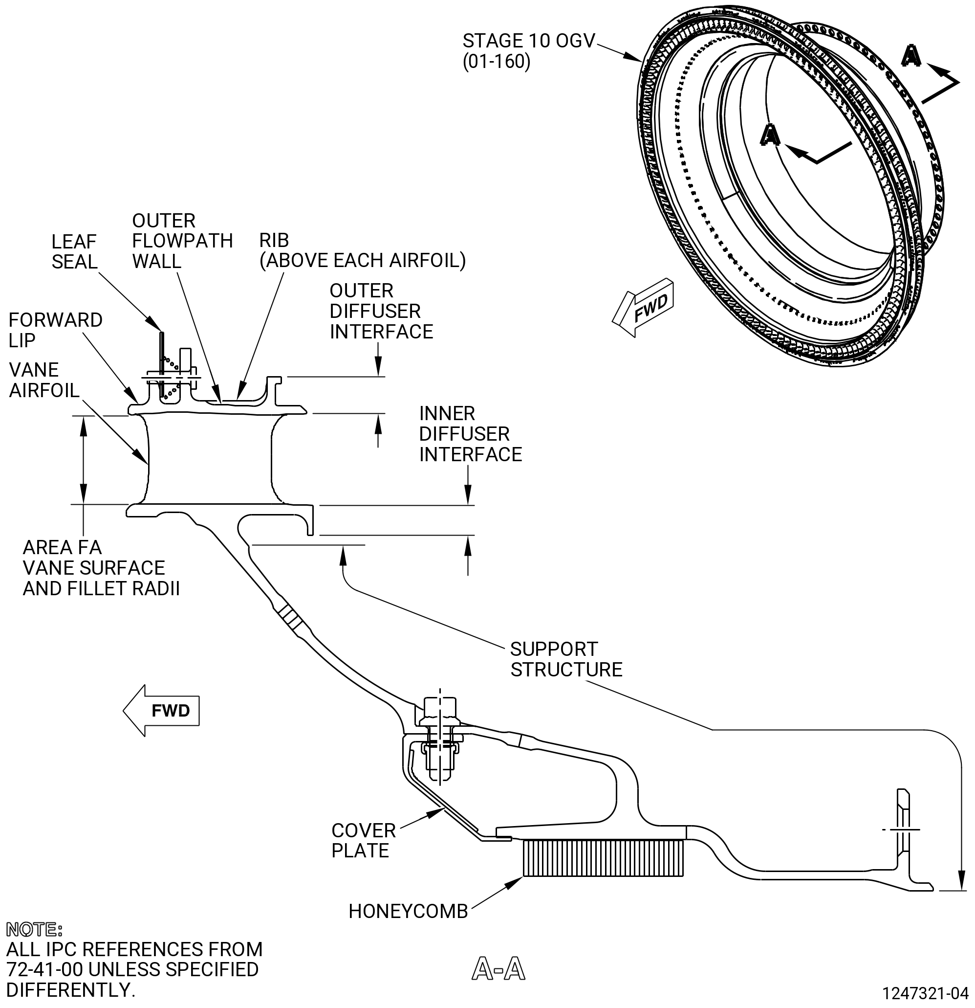
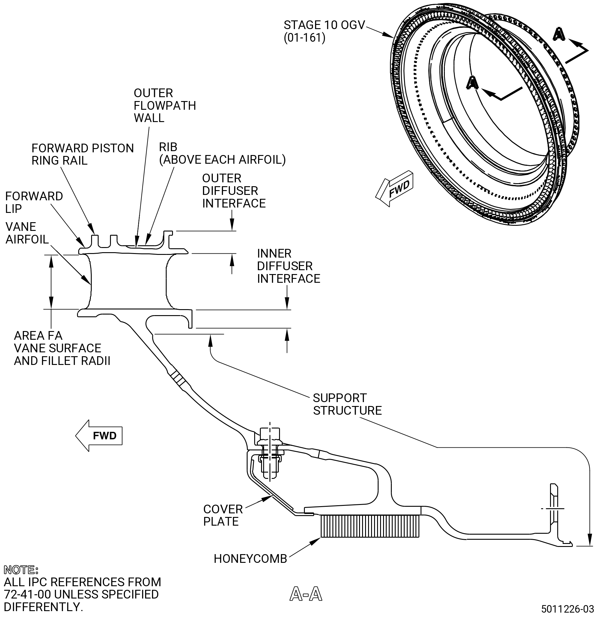
| (2) | All remaining (non-welded areas) FPI permitted indications are specified as follows. Refer to Figure 801. |
| • |
|
| • |
|
| • |
|
| • |
|
| 4 . | Visual Inspection. |
| Subtask 72-41-20-220-110 |
| A. | Do a visual inspection of the stage 10 OGV. Refer to Figure 801 and as follows: |
| (1) | Unless otherwise specified, visual inspection limits for size and spacing must be the same as the FPI criteria. Refer to Subtask 72-41-20-230-001 (paragraph 3.A.). |
| NOTE: |
|
| Subtask 72-41-20-220-001 |
| B. | Do an inspection of the vane airfoil leading and trailing edge for: |
| (1) | Alternative Procedure Available. Cracks and tears at the leading edge: |
| Maximum serviceable limit: |
|
| Maximum repairable limit: |
|
| Repair method: |
|
| Subtask 72-41-20-220-083 |
| (1).A. | Alternative Procedure. Cracks and tears at the leading edge: |
| Maximum serviceable limit: |
|
| Repair method: |
|
| Subtask 72-41-20-220-084 |
| (2) | Alternative Procedure Available. Cracks and tears at the trailing edge: |
| Maximum serviceable limit: |
|
| Maximum repairable limit: |
|
| Repair method: |
|
| Subtask 72-41-20-220-107 |
| (2).A. | Alternative Procedure. Cracks and tears at the trailing edge: |
| Maximum serviceable limit: |
|
| Repair method: |
|
| Subtask 72-41-20-220-108 |
| (3) | Cracks and tears in airfoil (concave and convex) areas other than the leading and trailing edges (does not include airfoil fillets): |
| Maximum serviceable limit: |
|
| Repair method: |
|
| Subtask 72-41-20-220-002 |
| C. | Do an inspection of all surfaces (except fillets) for: |
| (1) | Nicks, dents, and scratches: |
| Maximum serviceable limit: |
|
| Maximum repairable limit: |
|
| Repair method: |
|
| Subtask 72-41-20-220-003 |
| D. | Do an inspection of the fillets for: |
| (1) | Nicks, dents, scratches, cracks, and tears: |
| Maximum serviceable limit: |
|
| Repair method: |
|
| Subtask 72-41-20-220-004 |
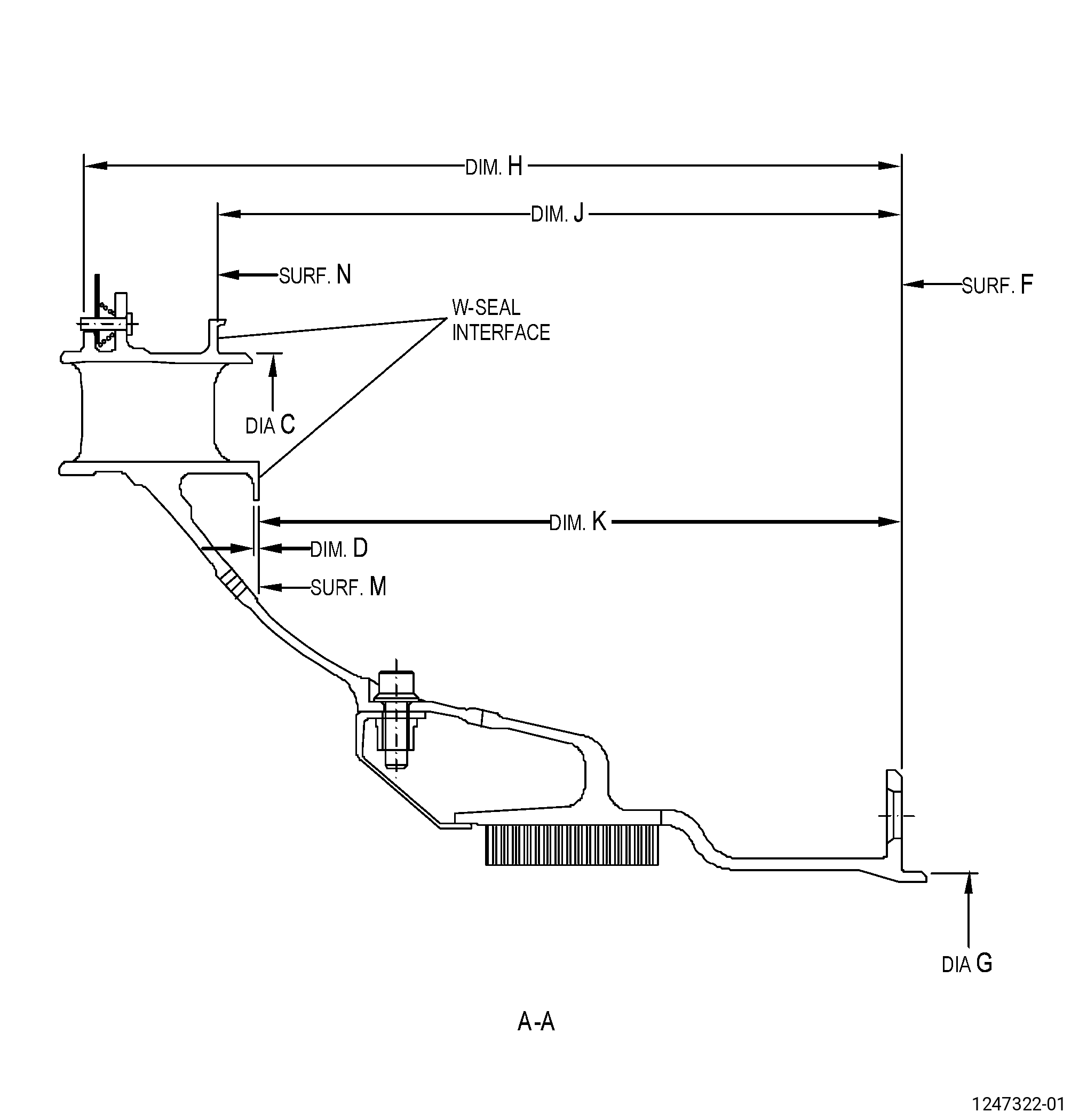
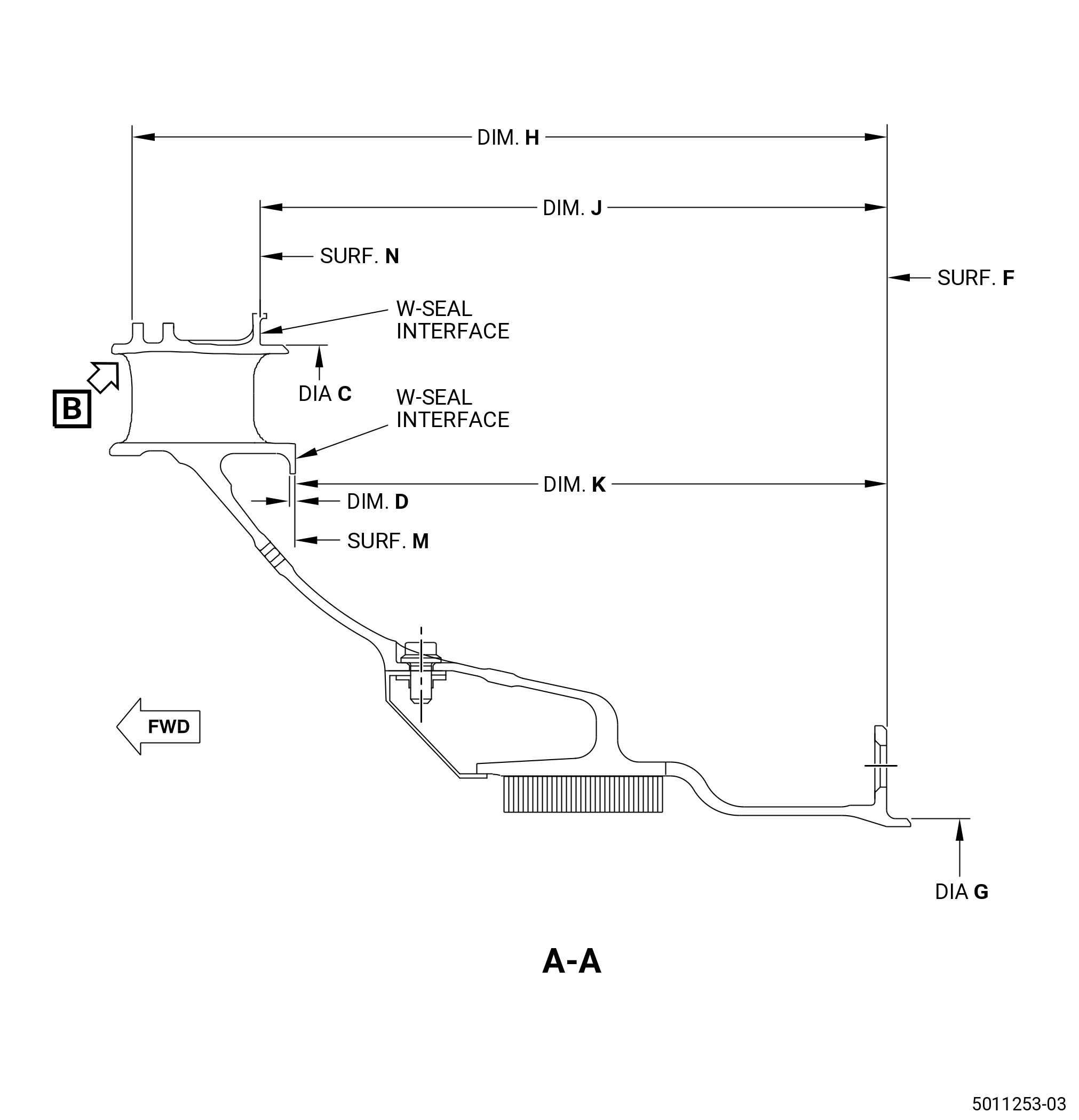
| E. | Do an inspection of the wear coat on diameter C for the following. Refer to Figure 802. |
| (1) | Wear-through of the wear coat: |
| Maximum serviceable limit: |
|
| Maximum repairable limit: |
|
| Repair method: |
|
| Subtask 72-41-20-220-028 |
| (2) | Missing wear coat: |
| Maximum serviceable limit: |
|
| Maximum repairable limit: |
|
| Repair method: |
|
| Subtask 72-41-20-220-029 |
| (3) | Craze cracking: |
| Maximum serviceable limit: |
|
| Repair method: |
|
| Subtask 72-41-20-220-030 |
| F. | Do an inspection of the wear coat on surface N for the following. Refer to Figure 802. |
| (1) | Wear-through of the wear coat: |
| Maximum serviceable limit: |
|
| Maximum repairable limit: |
|
| Repair method: |
|
| Subtask 72-41-20-220-031 |
| (2) | Missing wear coat: |
| Maximum serviceable limit: |
|
| Maximum repairable limit: |
|
| Repair method: |
|
| Subtask 72-41-20-220-032 |
| (3) | Craze cracking: |
| Maximum serviceable limit: |
|
| Repair method: |
|
| Subtask 72-41-20-220-005 |
| * * * PRE SB 72-0155 |
| G. | Do an inspection of the leaf seal for: |
| (1) | Dents, tears, and cracks: |
| Maximum serviceable limit: |
|
| Repair method: |
|
| Subtask 72-41-20-220-006 |
| (2) | Wear: |
| Maximum serviceable limit: |
|
| Repair method: |
|
| Subtask 72-41-20-220-007 |
| (3) | Leaf seal missing: |
| Maximum serviceable limit: |
|
| Repair method: |
|
| Subtask 72-41-20-220-008 |
| (4) | Compressed or missing spring: |
| Maximum serviceable limit: |
|
| Repair method: |
|
| Subtask 72-41-20-220-009 |
| (5) | Pin hole elongation: |
| Maximum serviceable limit: |
|
| Repair method: |
|
| Subtask 72-41-20-220-010 |
| (6) | Pin wear: |
| Maximum serviceable limit: |
|
| Repair method: |
|
| * * * END PRE SB 72-0155 |
| Subtask 72-41-20-220-085 |
| * * * SB 72-0155 |
| H. | Do an inspection of the forward piston ring rail for: |
| (1) | Wear: |
| Maximum serviceable limit: |
|
| Repair method: |
|
| Subtask 72-41-20-220-113 |
| I. | Do an inspection of the inner band for: |
| (1) | Nicks, dents, scratches, wear: |
| Minimum serviceable limit: |
|
| Maximum repairable limit: |
|
| Repair method: |
|
| * * * END SB 72-0155 |
| Subtask 72-41-20-220-011 |
| J. | Do an inspection of the CDP seal honeycomb for: |
| (1) | Annular wear grooves: |
| Maximum serviceable limit: |
|
| Repair method: |
|
| Subtask 72-41-20-220-012 |
| (2) | Cell damage/erosion (does not include the area forward of the forward annular wear groove): |
| Maximum serviceable limit: |
|
| Repair method: |
|
| Subtask 72-41-20-220-013 |
| (3) | Cell damage/erosion forward of the forward annular wear groove: |
| Maximum serviceable limit: |
|
| Repair method: |
|
| Subtask 72-41-20-220-014 |
| K. | Do an inspection of the support structure for: |
| (1) | Nicks and scratches: |
| Maximum serviceable limit: |
|
| Maximum repairable limit: |
|
| Repair method: |
|
| Subtask 72-41-20-220-015 |
| (2) | Cracks: |
| Maximum serviceable limit: |
|
| Repair method: |
|
| Subtask 72-41-20-220-016 |
| (3) | Dents: |
| Maximum serviceable limit: |
|
| Repair method: |
|
| Subtask 72-41-20-220-017 |
| L. | Do an inspection of the OGV ribs above the airfoils for: |
| (1) | Nicks, dents, and scratches: |
| Maximum serviceable limit: |
|
| Maximum repairable limit: |
|
| Repair method: |
|
| Subtask 72-41-20-220-038 |
| M. | Do an inspection of the cover plate self-locking nut assembly for: |
| NOTE: |
|
| (1) | Damaged self-locking nut or partial seized bolts: |
| Maximum serviceable limit: |
|
| Repair method: |
|
| Subtask 72-41-20-220-046 |
| N. | Do an inspection of the wear coat on surface M for the following. Refer to Figure 802. |
| (1) | Wear-through of the wear coat: |
| Maximum serviceable limit: |
|
| Repair method: |
|
| Subtask 72-41-20-220-047 |
| (2) | Missing wear coat: |
| Maximum serviceable limit: |
|
| Repair method: |
|
| Subtask 72-41-20-220-048 |
| (3) | Craze cracking: |
| Maximum serviceable limit: |
|
| Repair method: |
|
| Subtask 72-41-20-220-092 |
| O. | Do an inspection of the forward lip for: |
| (1) | Cracks, nicks, tears, and missing material: |
| Maximum serviceable limit: |
|
| Maximum repairable limit: |
|
| Repair method: |
|
| Maximum repairable limit: |
|
| Repair method: |
|
| 5 . | Dimensional Inspection. |
| Refer to Figure 802. |
| Subtask 72-41-20-220-018 |
| A. | Use the 11C4201 restrain fixture (or an applicable alternative) to hold diameter G round to less than 0.006 inch (0.15 mm), unless specified differently. Hold surface F flat to less than 0.002 inch (0.05 mm). |
| Subtask 72-41-20-220-019 |
| B. | Measure the diameter dimension at eight equally spaced locations and calculate the average of the measurements. |
| Subtask 72-41-20-220-020 |
| C. | Do an inspection of the stage 10 OGV for: |
| (1) | Diameter C: |
| Minimum serviceable limit: |
|
| Maximum serviceable limit: |
|
| Repair method: |
|
| Subtask 72-41-20-220-022 |
| (2) | Dimension D: |
| Minimum serviceable limit: |
|
| Repair method: |
|
| Subtask 72-41-20-220-024 |
| (3) | Diameter G: |
| Minimum serviceable limit: |
|
| Maximum serviceable limit: |
|
| Repair method: |
|
| Subtask 72-41-20-220-025 |
| (4) | Diameter G roundness (free state): |
| Maximum serviceable limit: |
|
| Repair method: |
|
| Subtask 72-41-20-220-026 |
| (5) | Surface F flatness (free state): |
| Maximum serviceable limit: |
|
| Repair method: |
|
| Subtask 72-41-20-220-027 |
| * * * FOR PART NUMBERS 2303M16G04, 2303M16G06, 2303M16G07, 2303M16G08, 2763M05G05, 2763M05G06, AND 2763M05G07 ONLY: |
| (6) | Dimension H: |
| Minimum serviceable limit: |
|
| Maximum serviceable limit: |
|
| Repair method: |
|
| Subtask 72-41-20-220-114 |
| * * * FOR PART NUMBERS 2763M05G02, 2763M05G03, AND 2763M05G04 ONLY: |
| (6).A. | Dimension H: |
| Minimum serviceable limit: |
|
| Maximum serviceable limit: |
|
| Repair method: |
|
| Subtask 72-41-20-220-033 |
| (7) | Dimension J: |
| Minimum serviceable limit: |
|
| Maximum serviceable limit: |
|
| Repair method: |
|
| Subtask 72-41-20-220-034 |
| (8) | Dimension K: |
| Minimum serviceable limit: |
|
| Maximum serviceable limit: |
|
| Repair method: |
|
| Subtask 72-41-20-220-086 |
| * * * SB 72-0155 |
| * * * SB 72-0349( FOR PART NUMBERS 2303M16G04, 2303M16G06, 2303M16G07, 2763M05G02, 2763M05G03, AND 2763M05G04 ONLY ) |
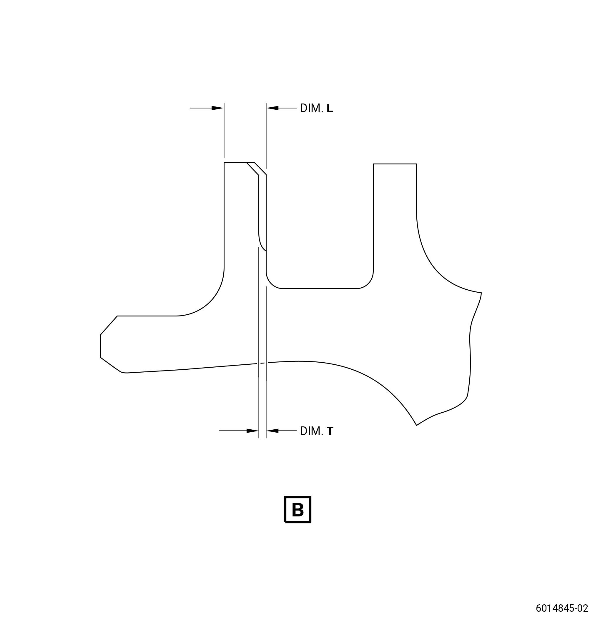
| (9) | Dimension L: |
| Minimum serviceable limit: |
|
| Maximum serviceable limit: |
|
| Repair method: |
|
| Subtask 72-41-20-220-111 |
| * * * SB 72-0349( FOR PART NUMBERS 2763M05G05, 2763M05G06, 2763M05G07, AND 2303M16G08 ONLY ) |
| (10) | Dimension L: |
| Minimum serviceble limit: |
|
| Maximum serviceable limit: |
|
| Repair method: |
|
| Subtask 72-41-20-220-112 |
| (11) | Dimension T: |
| Maximum serviceable limit: |
|
| Repair method: |
|
| * * * END SB 72-0349 |
| * * * END SB 72-0155 |