| GENX-1B CLEANING,INSPECTION,AND REPAIR MANUAL | Dated: 10/09/2024 | |
| CIR 72-41-20 , REPAIR 009 | ||
| STAGE 10 OUTLET GUIDE VANE - REPAIR - WELD REPAIR FOR DAMAGE ON THE FORWARD LIP | ||
| GENX-1B CLEANING,INSPECTION,AND REPAIR MANUAL | Dated: 10/09/2024 | |
| CIR 72-41-20 , REPAIR 009 | ||
| STAGE 10 OUTLET GUIDE VANE - REPAIR - WELD REPAIR FOR DAMAGE ON THE FORWARD LIP | ||
| * * * FOR ALL |
| TASK 72-41-20-300-809 |
| 1 . | Weld Repair for Damage on the Forward Lip. |
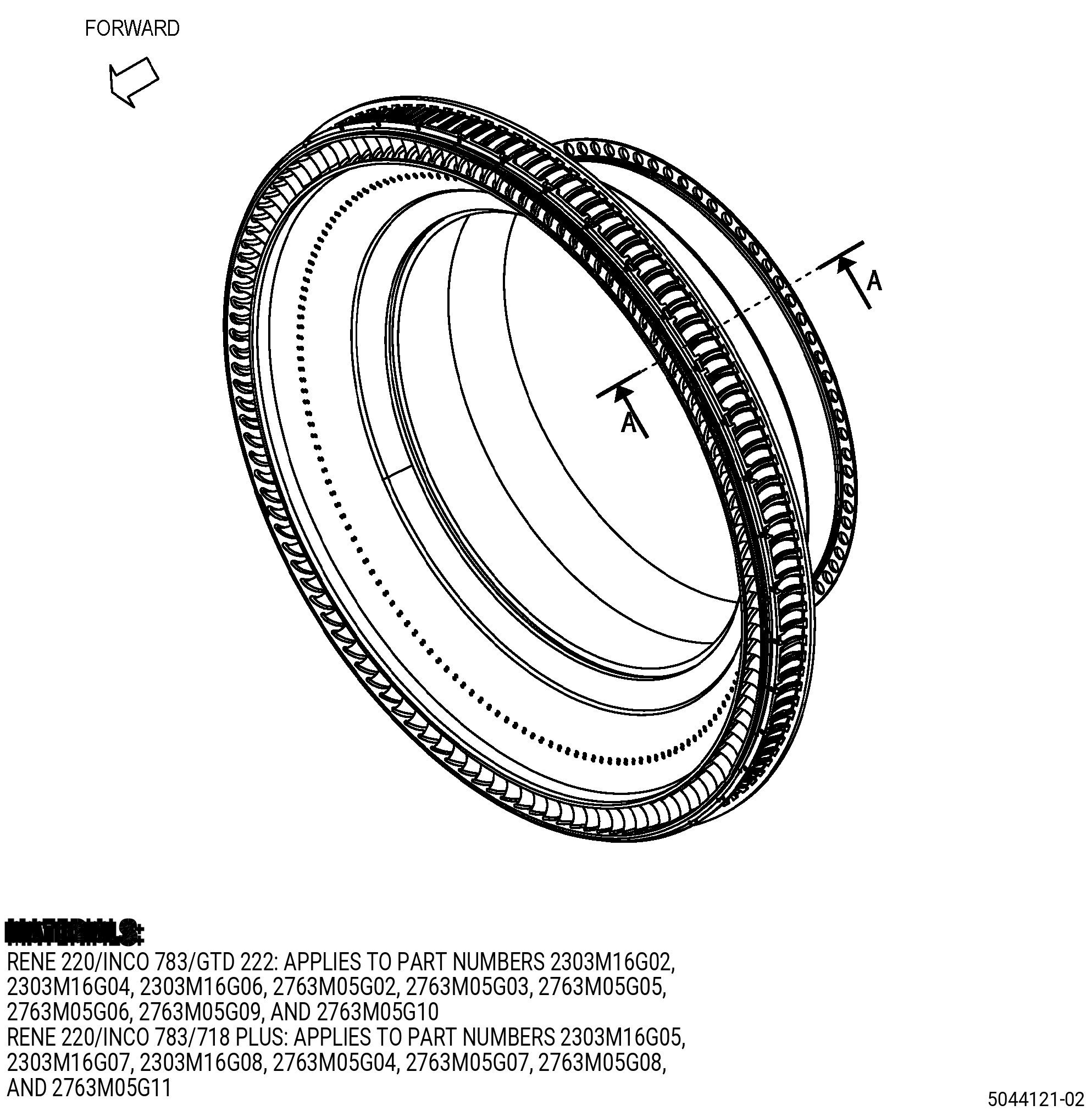
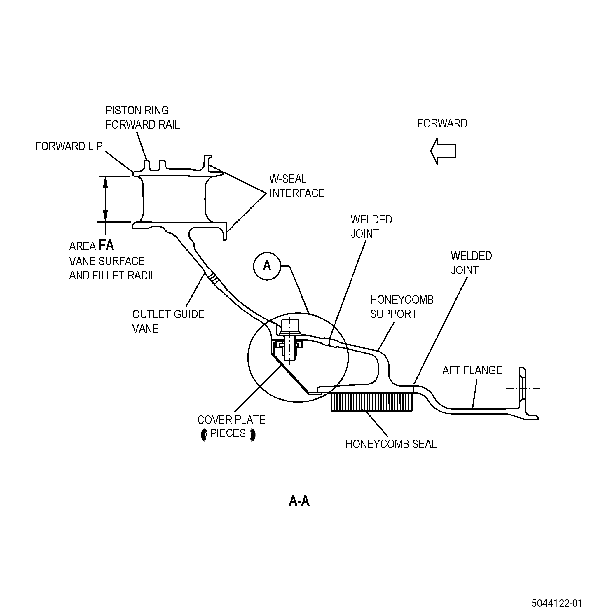
| A. | This procedure gives instructions to repair the stage 10 outlet guide vane (OGV) by welding the forward lip. Refer to Figure 901. |
| B. | The following maximum repairable limits apply to this repair: |
| NOTE: |
|
| (4) | Visual Inspection. |
| (m) | Do an inspection of the forward lip for: |
| 1 | Cracks, nicks, tears, and missing material: |
| Maximum repairable limit: |
|
| C. | The subsequent table gives a list of the part numbers that are applicable to this repair. All part numbers are applicable to all paragraphs unless specified differently. |
|
||||||||||||||||||||||||||||||||||||||||||||||||||||||||||||||
| D. | Proprietary/Complex Process Statement. |
| (1) | None. |
| 2 . | Tools, Equipment, and Materials. |
| NOTE: |
|
| A. | Tools and Equipment. |
| (1) | Special Tools. None. |
| (2) | Standard Tools and Equipment. None. |
| (3) | Locally Manufactured Tools. |
|
| B. | Consumable Materials. |
|
| C. | Referenced Procedures. |
| D. | Expendable Parts. None. |
| E. | SPD Information. |
| (1) | Locally Manufactured SPD. None. |
| F. | Special Solutions. None. |
| G. | Test Specimens. None. |
| 3 . | Dimensional Information. |
| Subtask 72-41-20-220-123 |
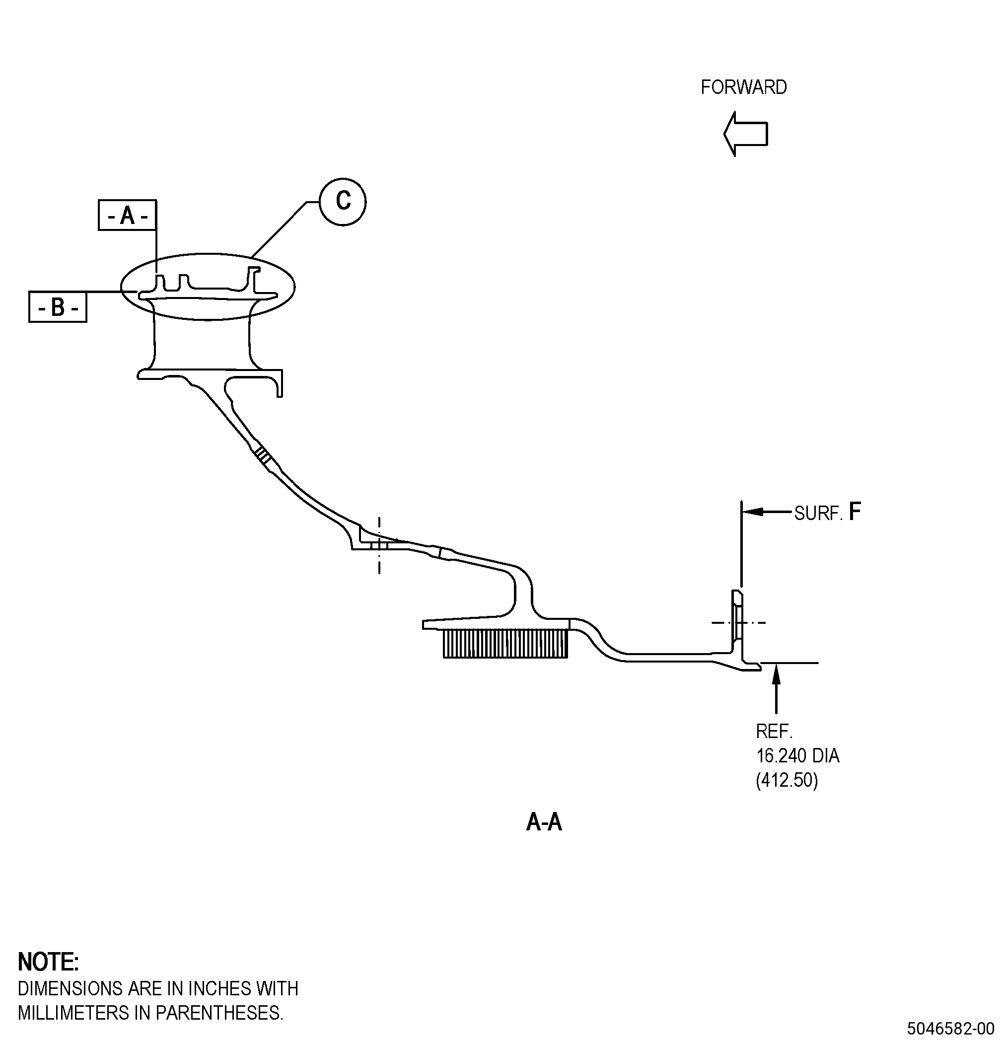
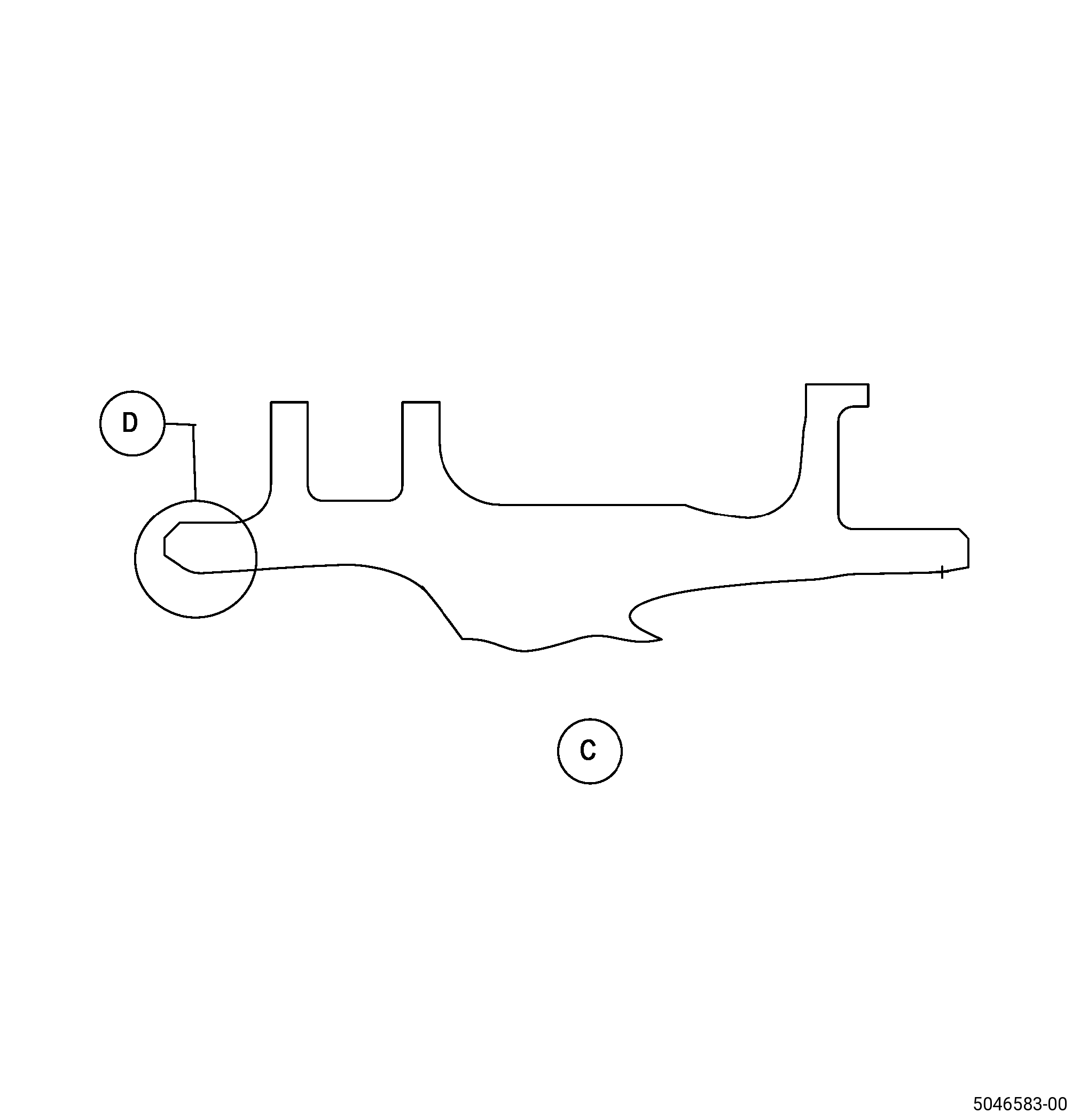
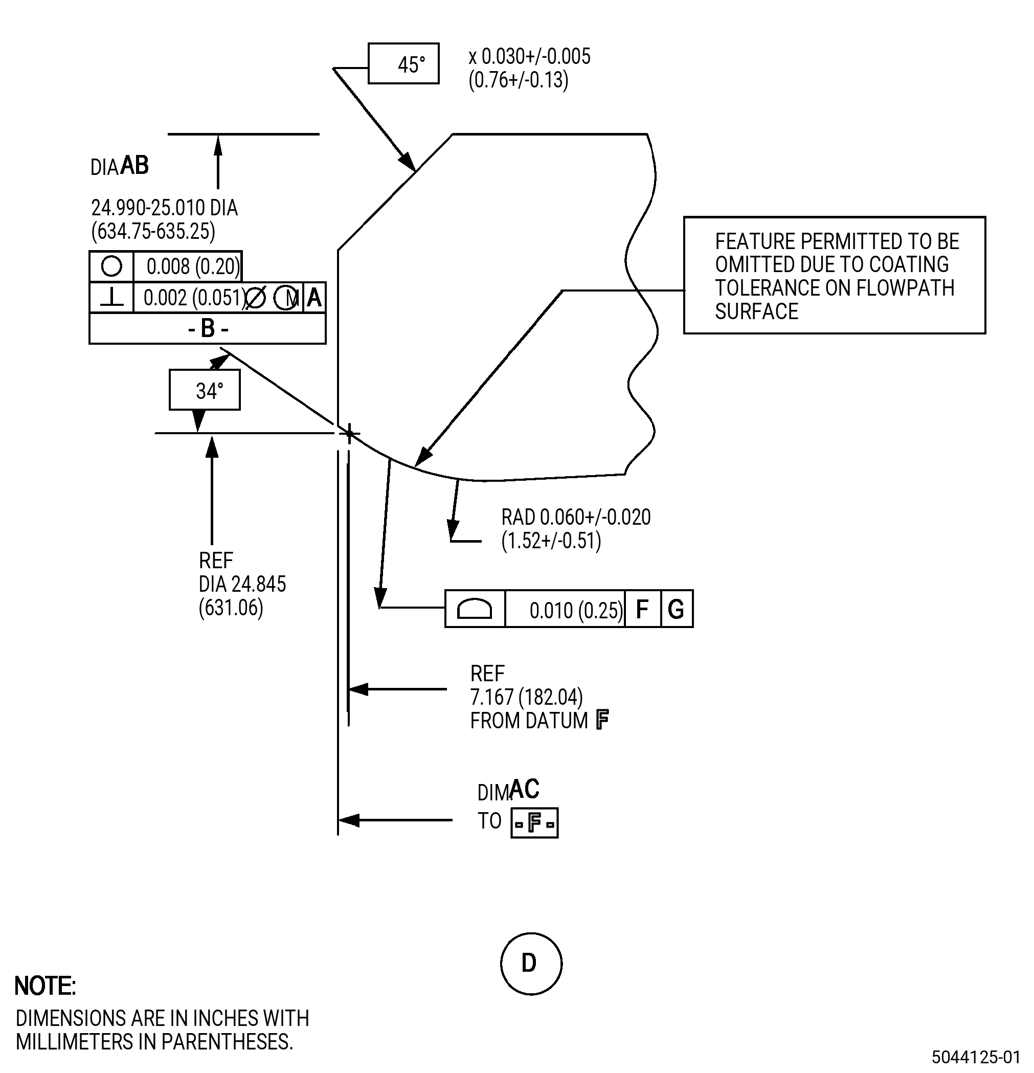
| A. | Refer to Figure 901 for specified dimensions and locations. |
| NOTE: |
|
| NOTE: |
|
| NOTE: |
|
| NOTE: |
|
|
||||||||||||||||||||||||||||||||||||||||||||||||||||||||||||||||||||||||||||||||||||||||||||||||||||||||||||||||||||||||||||||||||||||||||||||||||||||||||||||||||||||||
| 4 . | Setup Information. |
| Subtask 72-41-20-350-061 |
| A. | Set-up the OGV for machining as follows: |
| Subtask 72-41-20-930-002 |
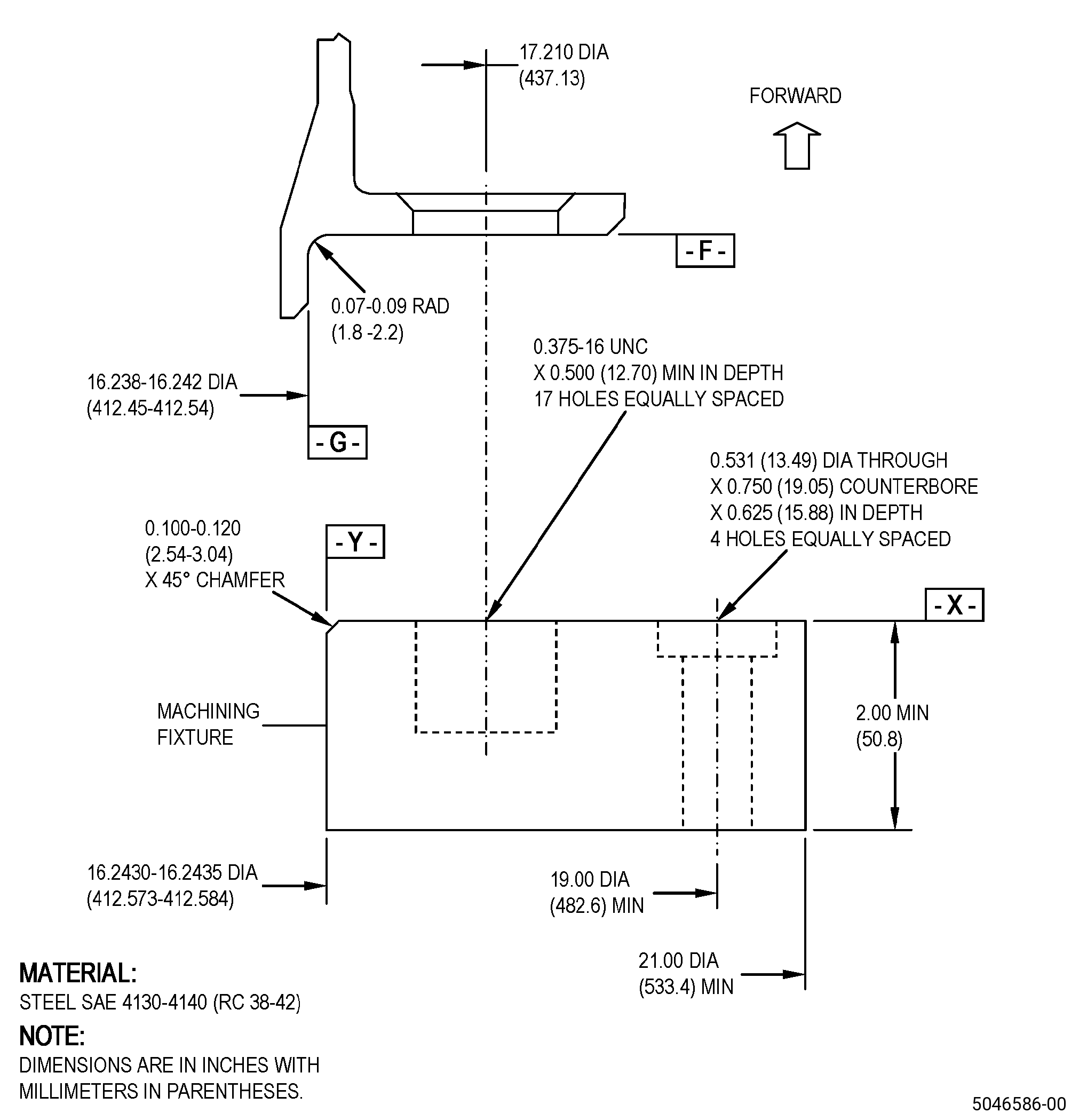
| (1) | If necessary, make the machining fixture. Refer to Figure 903. |
| Subtask 72-41-20-350-062 |
| (2) | Install the machining fixture on the machining table as follows: |
| (a) | Adjust the position of the machining fixture to get the runout of surface X to 0.001 inch (0.02 mm) FIR or less as follows: |
| 1 | If necessary, put C10-155 shims between the machining fixture and the machining table to get the necessary runout. |
| (b) | If necessary, adjust the position of the machining fixture to make sure that the runout of diameter Y is 0.001 inch (0.02 mm) FIR or less. |
| (c) | Use four 0.500-13 UNC socket-head capscrews to hold the machining fixture to the machining table and as follows: |
| 1 | Make sure that the runouts of surface X and diameter Y agree with the requirements specified in Subtask 72-41-20-350-062 (paragraph 4.A.(2)(a)) and Subtask 72-41-20-350-062 (paragraph 4.A.(2)(b)). |
| (3) | Install the OGV onto the machining fixture as follows: |
| NOTE: |
|
| (a) | Put the OGV onto the machining fixture, forward side up, and align the boltholes in the flange with the 17 threaded holes in the machining fixture. |
| (b) | Attach the OGV to the machining fixture with seventeen 0.375-16 UNC bolts or screws. |
| (4) | Make sure that the OGV is installed flat on the machining fixture as follows: |
| (a) | The maximum permitted clearance between surface X of the machining fixture and surface F of the OGV is 0.002 inch (0.05 mm). |
| Subtask 72-41-20-350-063 |
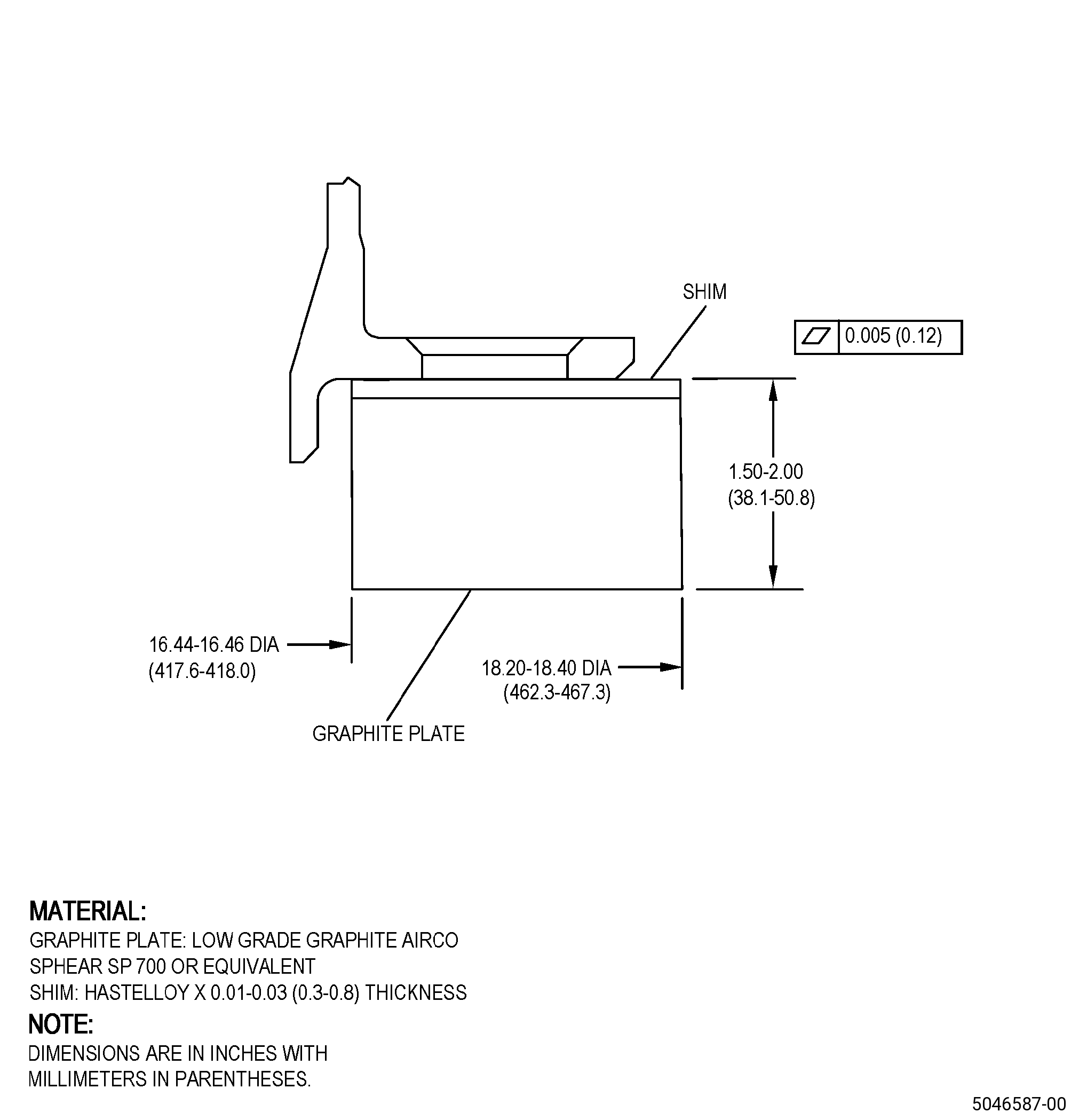
| B. | Set-up the OGV for heat-treating. Refer to Figure 904 and as follows: |
| Subtask 72-41-20-930-003 |
| (1) | If necessary, make the heat-treat fixture. Refer to Figure 904. |
| Subtask 72-41-20-350-064 |
| (2) | Put the graphite plate on a furnace grid. |
| (3) | Put C10-155 shims on top of the graphite plate. |
| (4) | Put the OGV onto the graphite plate and C10-155 shims as follows: |
| (a) | Make sure that the position of the OGV is aft end down. |
| 5 . | Procedure. |
| Subtask 72-41-20-160-011 |
| A. | If necessary, clean the OGV. Refer to TASK 72-41-20-100-801 (72-41-20, CLEANING 001). |
| Subtask 72-41-20-350-065 |
| B. | If necessary, remove the cover plates from the OGV. Refer to TASK 72-41-20-300-802 (72-41-20, REPAIR 003). |
| NOTE: |
|
| Subtask 72-41-20-350-066 |
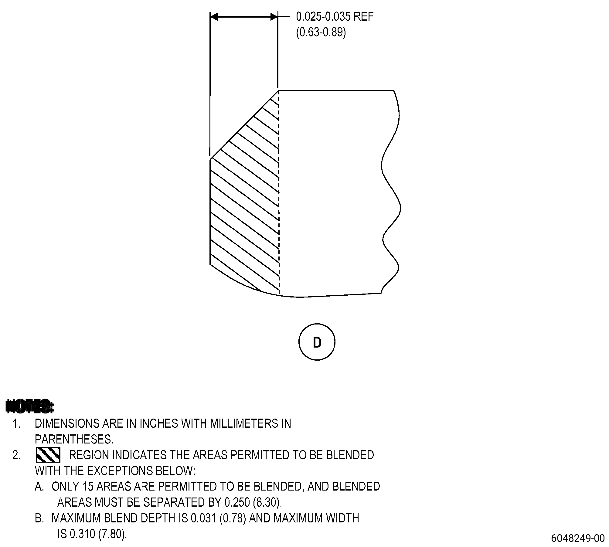
| C. | Blend the damage on the forward lip. Refer to TASK 70-42-00-350-002 (BLENDING AND REMOVAL OF HIGH METAL PROCEDURES), Figure 901, and as follows: |
| CAUTION: |
|
| (1) | Blend the defects to create a smooth surface with the adjacent surfaces. |
| (2) | A maximum of 15 areas can be blended on the forward lip, and the blend areas must be separated by a distance of 0.250 inch (6.35 mm). |
| (3) | Post blend, the maximum permitted depth of blend is 0.031 inch (0.78 mm) and the maximum width is 0.310 inch (7.87 mm). |
| (4) | Remove all burrs and break sharp edges to 0.005-0.010 inch (0.13-0.25 mm). |
| (5) | If the blend areas do not agree with the criteria above, prepare the area(s) for welding. Refer to Subtask 72-41-20-310-009 (paragraph 5.G.). |
| Subtask 72-41-20-110-022 |
| D. | Etch the lip area. Refer to TASK 70-24-00-110-033 (ETCHING PROCEDURES FOR FLUORESCENT-PENETRANT INSPECTION), TASK 70-24-01-110-034 (SWAB ETCHING PROCEDURE), and as follows: |
| (1) | Use Class C etchant. |
| Subtask 72-41-20-230-012 |
| E. | Do an inspection of the lip area. Refer to TASK 70-32-00-200-002 (INDIRECT INSPECTION METHODS), TASK 70-32-03-230-002 (SPOT-FLUORESCENT-PENETRANT INSPECTION), and as follows: |
| (1) | Use Class A penetrant. |
| (2) | For acceptability limits, refer to TASK 72-41-20-200-801 (72-41-20, INSPECTION 001). |
| (3) | If the part does not agree with the acceptability limits, continue with Subtask 72-41-20-160-012 (paragraph 5.F.). |
| (4) | If the part agrees with the acceptability limits, do Subtask 72-41-20-350-069 (paragraph 5.R.) as necessary to make the part serviceable. |
| (5) | Deleted. |
| Subtask 72-41-20-160-012 |
| F. | If necessary, clean the OGV. Refer to TASK 72-41-20-100-801 (72-41-20, CLEANING 001). |
| Subtask 72-41-20-310-009 |
| G. | Weld the forward lip repair area. Refer to TASK 70-41-00-310-001 (WELDING AND BRAZING PRACTICES) and as follows: |
| (1) | Prepare the repair area for welding. |
| (2) | Make short passes and let the welded location decrease its temperature between each pass to keep the distortion to a minimum. |
| (3) | Use C06-039 Rene 220 weld wire. |
| (4) | Keep the heat input to a minimum during the welding procedure. |
| (5) | Multiple passes can be necessary to weld build-up the worn areas and agree with the parent metal thickness. |
| (6) | Make sure to put sufficient weld material to get the finish dimensions. |
| Subtask 72-41-20-350-067 |
| H. | Alternative Procedure Available. Blend the welded area of the OGV forward lip. Refer to TASK 70-42-00-350-002 (BLENDING AND REMOVAL OF HIGH METAL PROCEDURES), Figure 901, and as follows: |
| (1) | Blend carefully the welded areas to the finish dimensions. |
| (2) | Remove all burrs and sharp edges to 0.020 inch (0.50 mm) or less. |
| Subtask 72-41-20-320-013 |
| H.A. | Alternative Procedure. Machine the OGV forward lip. Refer to TASK 70-00-03-800-004 (MACHINING DATA), Subtask 72-41-20-220-123 (paragraph 3.A.), Figure 901, and as follows: |
| (1) | Set-up the OGV for machining. Refer to Subtask 72-41-20-350-061 (paragraph 4.A.). |
| (2) | Machine the OGV area D to the finish dimensions. Refer to Figure 901. |
| Subtask 72-41-20-350-068 |
| (2) | Blend the OGV repair area. Refer to TASK 70-42-00-350-002 (BLENDING AND REMOVAL OF HIGH METAL PROCEDURES) and as follows: |
| (a) | Break all sharp edges to 0.005-0.010 inch (0.13-0.25 mm). |
| Subtask 72-41-20-110-023 |
| I. | Etch the OGV repair area. Refer to TASK 70-24-00-110-033 (ETCHING PROCEDURES FOR FLUORESCENT-PENETRANT INSPECTION), TASK 70-24-01-110-034 (SWAB ETCHING PROCEDURE), and as follows: |
| (1) | Use Class C etchant. |
| Subtask 72-41-20-230-013 |
| J. | Do an inspection of the lip area. Refer to TASK 70-32-00-200-002 (INDIRECT INSPECTION METHODS), TASK 70-32-03-230-002 (SPOT-FLUORESCENT-PENETRANT INSPECTION), and as follows: |
| (1) | Use Class A penetrant. |
| (2) | For acceptability limits, refer to TASK 72-41-20-200-801 (72-41-20, INSPECTION 001). |
| (3) | Deleted. |
| Subtask 72-41-20-260-001 |
| K. | Deleted. |
| Subtask 72-41-20-310-010 |
| L. | Heat-treat the OGV. Refer to TASK 70-41-00-310-001 (WELDING AND BRAZING PRACTICES), TASK 70-41-03-310-004 (HIGH TEMPERATURE FURNACE BRAZE), and as follows: |
| NOTE: |
|
| (1) | Set-up the OGV for heat-treating. Refer to Subtask 72-41-20-350-063 (paragraph 4.B.) and Figure 904. |
| (2) | Attach four equally spaced thermocouples to the honeycomb support outer diameter. |
| (3) | Install the OGV in a clean vacuum furnace. |
| (4) | Decrease the vacuum furnace temperature to a vacuum of 5x10⁻⁴ Torr (0.5 micron) or better. |
| (5) | Increase the temperature of the OGV to a range of 1700 to 1800°F (927 to 982°C) and as follows: |
| (a) | Keep the temperature of the OGV at a range of 1700 to 1800°F (927 to 982°C) for 10-15 minutes. |
| (6) | Increase the temperature of the OGV to a range of 1900 to 1950°F (1038 to 1065°C) at a rate of not more than 35°F (19°C) for each minute and as follows: |
| (a) | Keep the temperature of the OGV at the braze temperature until the braze alloy wets. |
| (b) | Do not keep the temperature of the OGV at the braze temperature for more than 5 minutes. |
| (7) | Decrease the temperature of the OGV to a range of 1700 to 1800°F (927 to 982°C) at a rate of not more than 35°F (19°C) for each minute and as follows: |
| (a) | Keep the temperature of the OGV at a range of 1700 to 1800°F (927 to 982°C) for 15 minutes maximum. |
| (8) | Decrease the temperature of the OGV to below 1100°F (593°C). |
| (9) | The temperature decrease from 1950°F (1065°C) maximum to below 1100°F (593°C) must be in 30 minutes or less. |
| (10) | The cooling rate below 1100°F (593°C) is not important. |
| Subtask 72-41-20-220-088 |
| M. | Alternative Procedure Available. Do an inspection of the braze joint on the replacement honeycomb seal and the OGV backing strip surface. Refer to TASK 70-33-00-999-001 (SPECIAL INSPECTION PROCEDURES), TASK 70-33-02-220-005 (CAPILLARY INSPECTION OF OPEN FACE HONEYCOMB STRUCTURES), and as follows: |
| (1) | Make sure that the honeycomb ring is fully bonded to its backing surface in 80 percent of the total contact area. |
| (2) | The contact area(s) of the honeycomb that are not bonded must agree with the limits that follow: |
| (a) | The unbonded area of the replacement honeycomb seal must be less than 10 fully adjacent cells circumferentially and five fully adjacent cells axially. |
| (b) | The unbonded areas must be separated by a minimum of five adjacent bonded cells. |
| (c) | The unbonded area of the replacement honeycomb seal must not include partial cells. |
| Subtask 72-41-20-220-089 |
| M.A. | Alternative Procedure. Do an inspection of the braze joint on the honeycomb seal and the OGV backing strip surface as follows: |
| (1) | Use a video microscope with 10X magnification. |
| (2) | Refer to the limits in Subtask 72-41-20-220-088 (paragraph 5.M.(1)) thru Subtask 72-41-20-220-088 (paragraph 5.M.(2)). |
| Subtask 72-41-20-370-007 |
| N. | Heat-treat the OGV in a vacuum furnace. Refer to TASK 70-44-00-800-010 (HEAT TREATING), TASK 70-44-03-370-004 (FURNACE HEAT TREATMENT), Figure 901, and as follows: |
| (1) | Set-up the OGV for heat-treating. Refer to Subtask 72-41-20-350-063 (paragraph 4.B.). |
| (2) | Attach four equally spaced thermocouples to the OGV. |
| (3) | Install the OGV setup in a clean vacuum furnace. |
| (4) | Decrease the furnace to a vacuum of 5x10⁻⁴ Torr (0.5 micron) or better. |
| (5) | Increase the temperature of the OGV to a range of 1450 to 1500°F (788 to 815°C) and as follows: |
| (a) | Keep the temperature of the OGV at a range of 1450 to 1500°F (788 to 815°C) for 8 hours and plus or minus 10 minutes. |
| (6) | Decrease the temperature of the OGV to a range of 1300 to 1350°F (705 to 732°C) and as follows: |
| (a) | Keep the temperature of the OGV at a range of 1300 to 1350°F (705 to 732°C) for 8 hours and plus or minus 10 minutes. |
| (7) | Decrease the temperature of the OGV to a range of 1125 to 1175°F (608 to 635°C) at a minimum rate of 100°F (38°C) for each hour and as follows: |
| (a) | Keep the temperature of the OGV at a range of 1125 to 1175°F (608 to 635°C) for 8 hours and plus or minus 10 minutes. |
| (5) | Increase the temperature of the OGV to a range of 1425 to 1475°F (774 to 801°C) and as follows: |
| (a) | Keep the temperature of the OGV at a range of 1425 to 1475°F (774 to 801°C) for 2 hours and plus or minus 15 minutes. |
| (6) | Decrease the temperature of the OGV to a range of 1275 to 1325°F (691 to 718°C) and as follows: |
| (a) | Keep the temperature of the OGV at a range of 1275 to 1325°F (691 to 718°C) for 8 hours and plus or minus 15 minutes. |
| (7) | Decrease the temperature of the OGV to a range of 1125 to 1175°F (608 to 635°C) and as follows: |
| (a) | Keep the temperature of the OGV at a range of 1125 to 1175°F (608 to 635°C) for 8 hours and plus or minus 15 minutes. |
| (8) | Decrease the temperature of the OGV to room temperature. |
| Subtask 72-41-20-230-014 |
| O. | Do an inspection of the OGV. Refer to TASK 70-32-00-200-002 (INDIRECT INSPECTION METHODS), TASK 70-32-02-230-001 (FLUORESCENT PENETRANT INSPECTION), Figure 901, and as follows: |
| (1) | Use Class A penetrant. |
| (2) | For acceptability limits, refer to TASK 72-41-20-200-801 (72-41-20, INSPECTION 001). |
| (3) | Deleted. |
| (4) | Deleted. |
| (5) | Do an inspection of the honeycomb support and the aft flange as specified in TASK 70-31-02-220-003 (ACCEPTABILITY LIMITS FOR FLUORESCENT PENETRANT INSPECTION) and as follows: |
| (a) | Use Class A limits. |
| (6) | Through indications are not permitted. |
| Subtask 72-41-20-220-090 |
| P. | Do an inspection of the OGV for thermal spray coating at the W-seal of surface N, W-seal of surface M, surface F, diameter G, and rabbet diameter C. Refer to TASK 72-41-20-200-801 (72-41-20, INSPECTION 001) and as follows: |
| (1) | Use 10X magnification and white light. |
| (2) | Do not lift or remove the thermal spray coating from the parent metal. |
| (3) | Cracks, blisters, chipping, flaking, spalling, or splatter are not permitted. |
| (4) | If the thermal spray coating is damaged, remove it and replace it. Refer to TASK 72-41-20-200-801 (72-41-20, INSPECTION 001). |
| Subtask 72-41-20-220-091 |
| Q. | Do a dimensional inspection of the OGV. Refer to TASK 72-41-20-200-801 (72-41-20, INSPECTION 001). |
| Subtask 72-41-20-350-069 |
| R. | Install the cover plates into the OGV. Refer to TASK 72-41-20-300-802 (72-41-20, REPAIR 003). |