| GENX-1B CLEANING,INSPECTION,AND REPAIR MANUAL | Dated: 06/05/2024 | |
| CIR 72-41-20 , REPAIR 008 | ||
| STAGE 10 OUTLET GUIDE VANE - REPAIR - WELD REPAIR OF THE AIRFOILS | ||
| GENX-1B CLEANING,INSPECTION,AND REPAIR MANUAL | Dated: 06/05/2024 | |
| CIR 72-41-20 , REPAIR 008 | ||
| STAGE 10 OUTLET GUIDE VANE - REPAIR - WELD REPAIR OF THE AIRFOILS | ||
| * * * FOR ALL |
| TASK 72-41-20-300-808 |
| 1 . | Weld Repair of the Airfoils. |
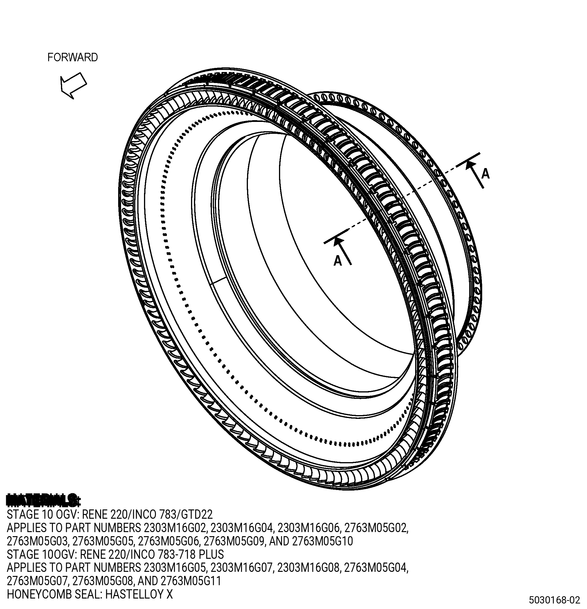
| A. | This procedure gives instructions to repair the stage 10 outlet guide vane (OGV) by welding the vane leading edge, trailing edge, concave areas, convex areas, and fillet radius to remove nicks, dents, scratches, cracks, and tears. Refer to Figure 901. |
| B. | The following maximum repairable limits apply to this repair: |
| NOTE: |
|
| (4) | Visual Inspection. |
| (b) | Do an inspection of the vane airfoil leading and trailing edge for: |
| 1.A. | Alternative Procedure. Cracks and tears at the leading edge: |
| Maximum repairable limit: |
|
| 2.A. | Alternative Procedure. Cracks and tears at the trailing edge: |
| Maximum repairable limit: |
|
| 3 | Cracks and tears in airfoil (concave and convex) areas other than the leading and trailing edges (does not include airfoil fillets): |
| Maximum repairable limit: |
|
| NOTE: |
|
| (c) | Do an inspection of the fillets for: |
| 1 | Nicks, dents, scratches, cracks, and tears: |
| Maximum repairable limit: |
|
| C. | The subsequent table gives a list of the part numbers that are applicable to this repair. All part numbers are applicable to all paragraphs unless specified differently. |
|
||||||||||||||||||||||||||||||||||||||||||||||||||||||||||||||
| D. | Proprietary/Complex Process Statement. |
| (1) | None. |
| 2 . | Tools, Equipment, and Materials. |
| NOTE: |
|
| A. | Tools and Equipment. |
| (1) | Special Tools. None. |
| (2) | Standard Tools and Equipment. |
|
| (3) | Locally Manufactured Tools. |
|
| B. | Consumable Materials. |
|
| C. | Referenced Procedures. |
| D. | Expendable Parts. None. |
| E. | SPD Information. |
| (1) | Spares Supplied. None. |
| (2) | Protected Spares. None. |
| (3) | Locally Manufactured Spares. None. |
| F. | Special Solutions. None. |
| G. | Test Specimens. None. |
| 3 . | Dimensional Information. |
| Subtask 72-41-20-220-079 |
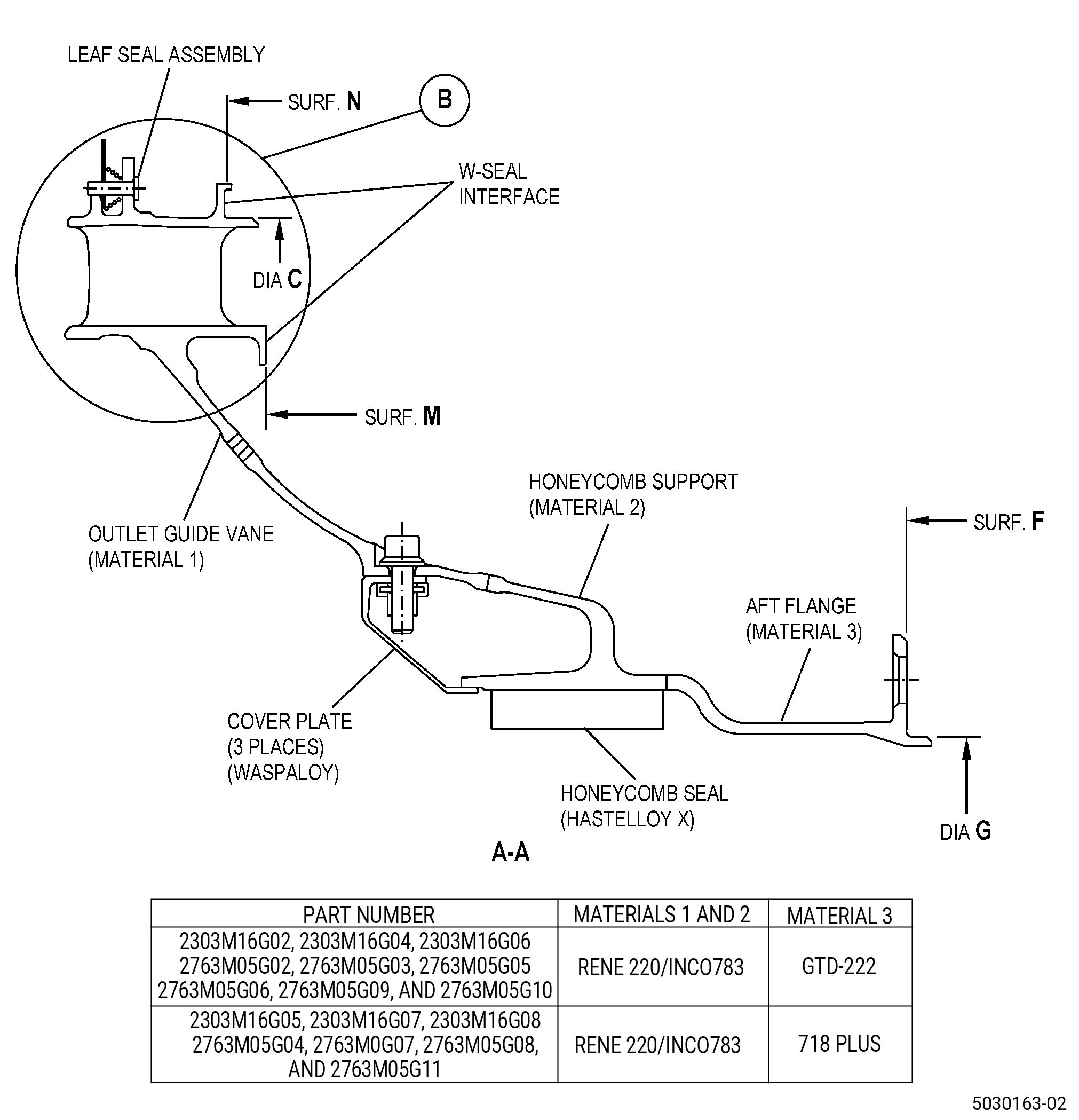
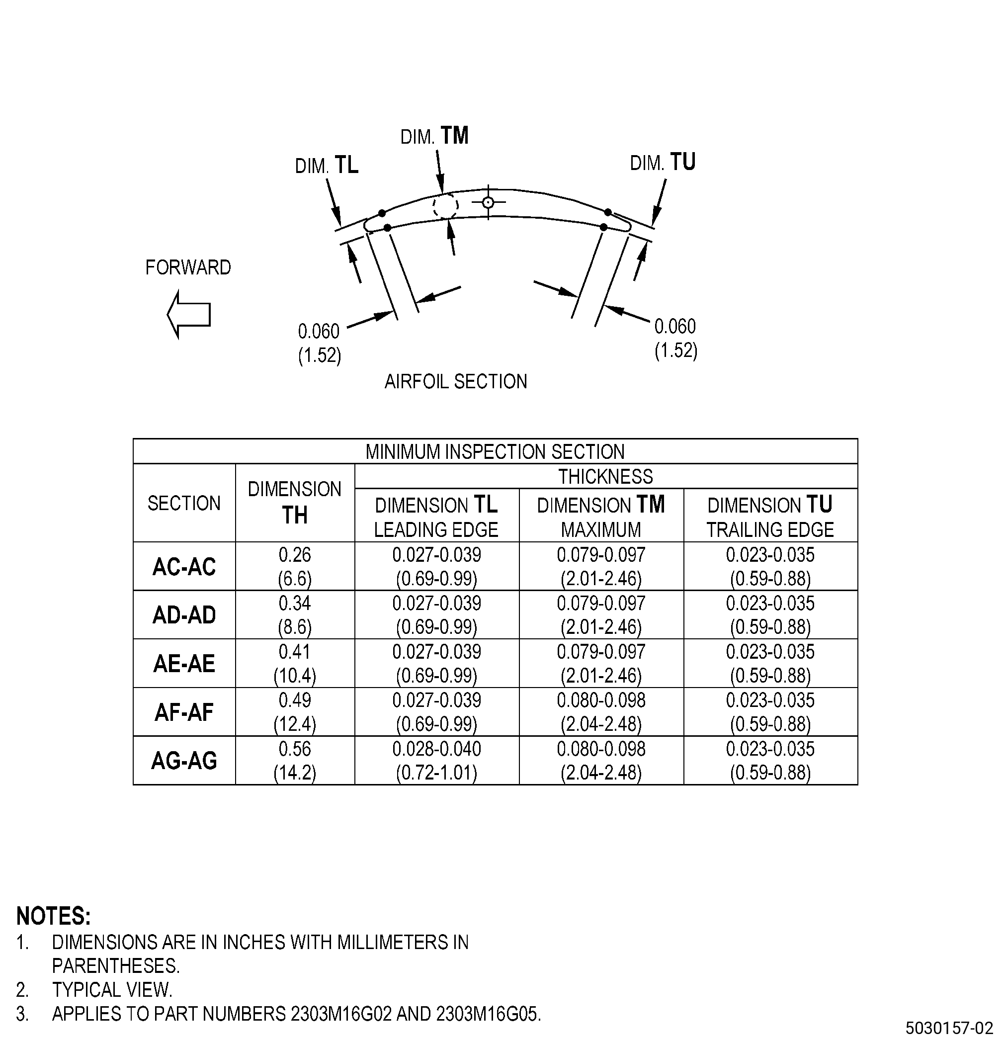
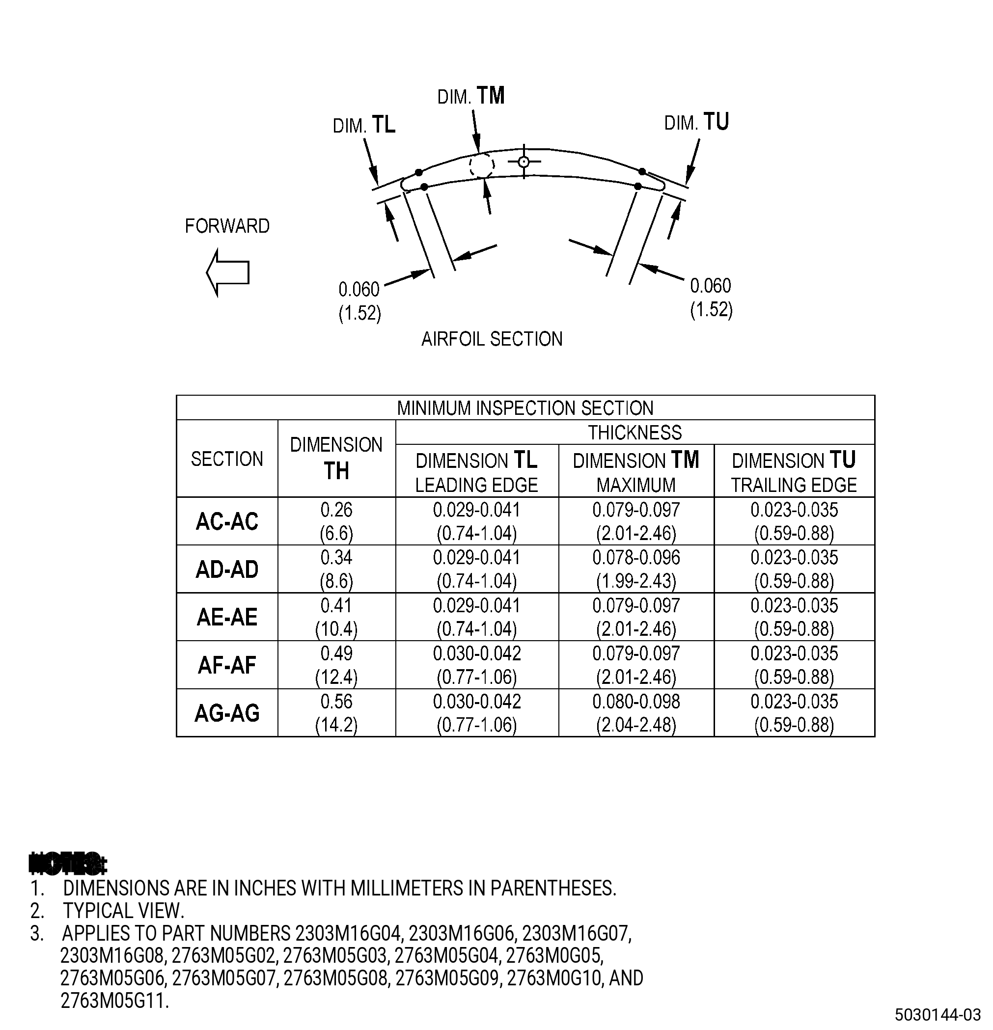
| A. | Refer to Figure 901 and Figure 902 for specified dimensions and locations. |
| NOTE: |
|
| NOTE: |
|
| 4 . | Setup Information. |
| Subtask 72-41-20-370-010 |
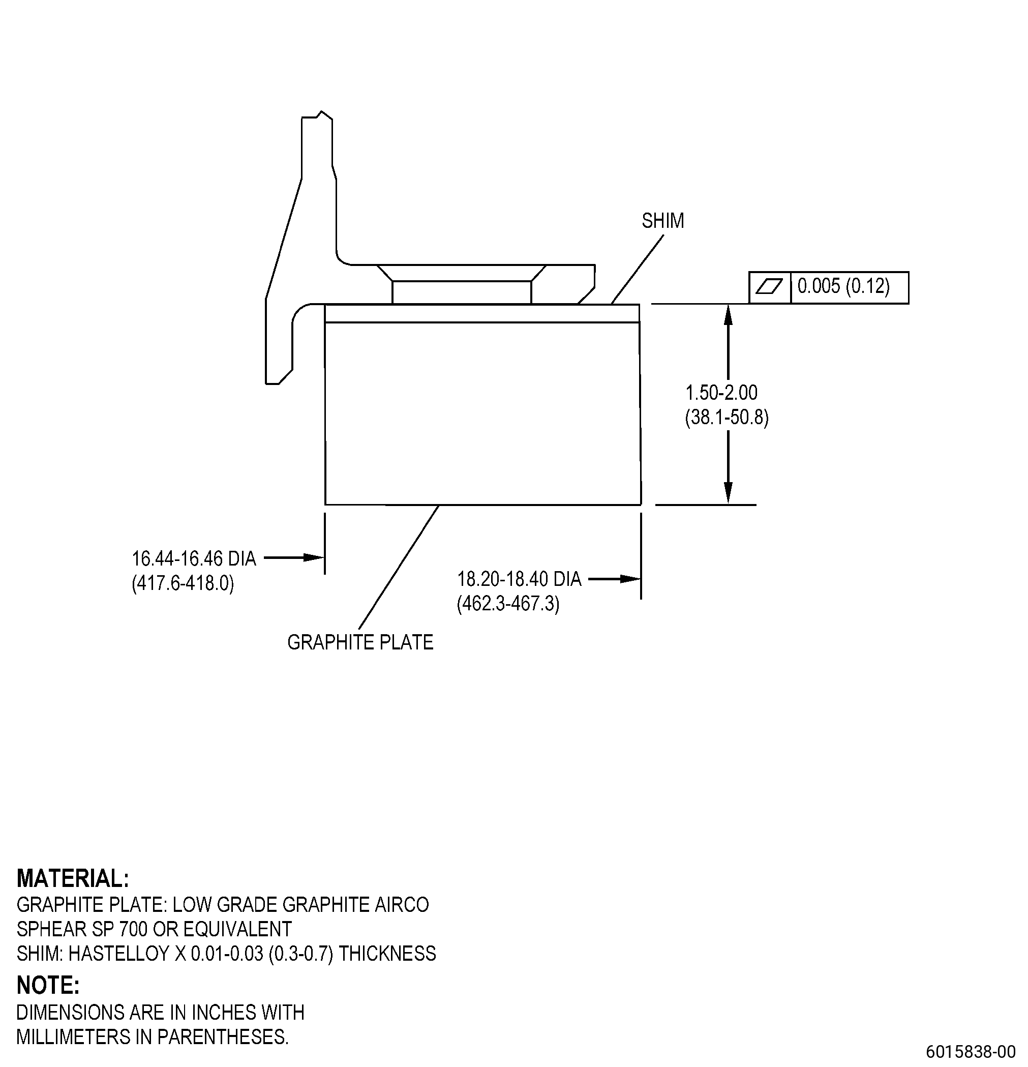
| A. | Set-up the OGV for heat treating. Refer to Figure 903 and as follows: |
| (1) | If necessary, make the heat-treat fixture. Refer to Figure 903. |
| (2) | Put the graphite plate on a furnace grid. |
| (3) | Put C10-155 shims on top of the graphite plate. |
| (4) | Put the OGV onto the graphite plate and C10-155 shims as follows: |
| (a) | Make sure that the position of the OGV is aft end down. |
| 5 . | Procedure. |
| Subtask 72-41-20-110-015 |
| A. | If necessary, clean the OGV. Refer to TASK 72-41-20-100-801 (72-41-20, CLEANING 001). |
| Subtask 72-41-20-350-048 |
| B. | For part number 2303M16G02 and part number 2303M16G05 remove the pins, springs, and leaf seals from the OGV. Refer to TASK 72-41-20-300-801 (72-41-20, REPAIR 001) and Figure 901. |
| Subtask 72-41-20-350-049 |
| C. | For part numbers 2303M16G04 , 2303M16G06 , 2303M16G07 , 2303M16G08 , 2763M05G02 , 2763M05G03 , 2763M05G04 , 2763M05G05 , 2763M05G06 , 2763M05G07 , 2763M05G08 , 2763M05G09 , 2763M05G10 , and 2763M05G11 remove the piston ring from the OGV. Refer to TASK 72-41-00-040-802 (72-41-00, DISASSEMBLY 001 - CONFIGURATION 02). |
| Subtask 72-41-20-350-050 |
| D. | Remove the cover plates from the OGV. Refer to TASK 72-41-20-300-802 (72-41-20, REPAIR 003). |
| Subtask 72-41-20-350-051 |
| E. | Optional Procedure. Remove the honeycomb from the OGV. Refer to TASK 72-41-20-300-804 (72-41-20, REPAIR 007). |
| Subtask 72-41-20-230-009 |
| F. | Do an inspection of the OGV to find thermal spray coating at surface F and diameter G. Refer to TASK 70-32-00-200-002 (INDIRECT INSPECTION METHODS), TASK 70-32-03-230-002 (SPOT-FLUORESCENT-PENETRANT INSPECTION), Figure 901, and as follows: |
| (1) | Use Class A penetrant. |
| NOTE: |
|
| (2) | If there is no thermal spray coating on the OGV, go to Subtask 72-41-20-350-052 (paragraph 5.G.). |
| (3) | If there is thermal spray coating, remove it from the OGV. Refer to TASK 72-41-20-300-807 (72-41-20, REPAIR 005). |
| Subtask 72-41-20-350-052 |
| G. | Blend the OGV to remove damage. Refer to TASK 70-42-00-350-002 (BLENDING AND REMOVAL OF HIGH METAL PROCEDURES) and as follows: |
| CAUTION: |
|
| (1) | Remove a minimum quantity of material to remove high metal and get a smooth contour before you do the welding procedure. |
| Subtask 72-41-20-110-016 |
| H. | Etch the OGV repair area. Refer to TASK 70-24-00-110-033 (ETCHING PROCEDURES FOR FLUORESCENT-PENETRANT INSPECTION), TASK 70-24-01-110-034 (SWAB ETCHING PROCEDURE), and as follows: |
| (1) | Use Class C etchant. |
| Subtask 72-41-20-230-010 |
| I. | Do an inspection of the OGV repair area. Refer to TASK 70-32-00-200-002 (INDIRECT INSPECTION METHODS), TASK 70-32-03-230-002 (SPOT-FLUORESCENT-PENETRANT INSPECTION), and as follows: |
| (1) | Use Class A penetrant. |
| (2) | Refer to TASK 72-41-20-200-801 (72-41-20, INSPECTION 001), for the acceptability limits. |
| Subtask 72-41-20-110-017 |
| J. | If necessary, clean the OGV. Refer to TASK 72-41-20-100-801 (72-41-20, CLEANING 001). |
| Subtask 72-41-20-310-008 |
| K. | Weld build-up the OGV repair areas. Refer to TASK 70-41-00-310-001 (WELDING AND BRAZING PRACTICES) and as follows: |
| (1) | Use C06-039 Rene 220 weld wire. |
| (2) | Weld build-up sufficient material to blend the OGV to the finish dimensions. |
| (3) | Keep the heat input to a minimum to prevent weld distortion in the OGV. |
| NOTE: |
|
| Subtask 72-41-20-350-053 |
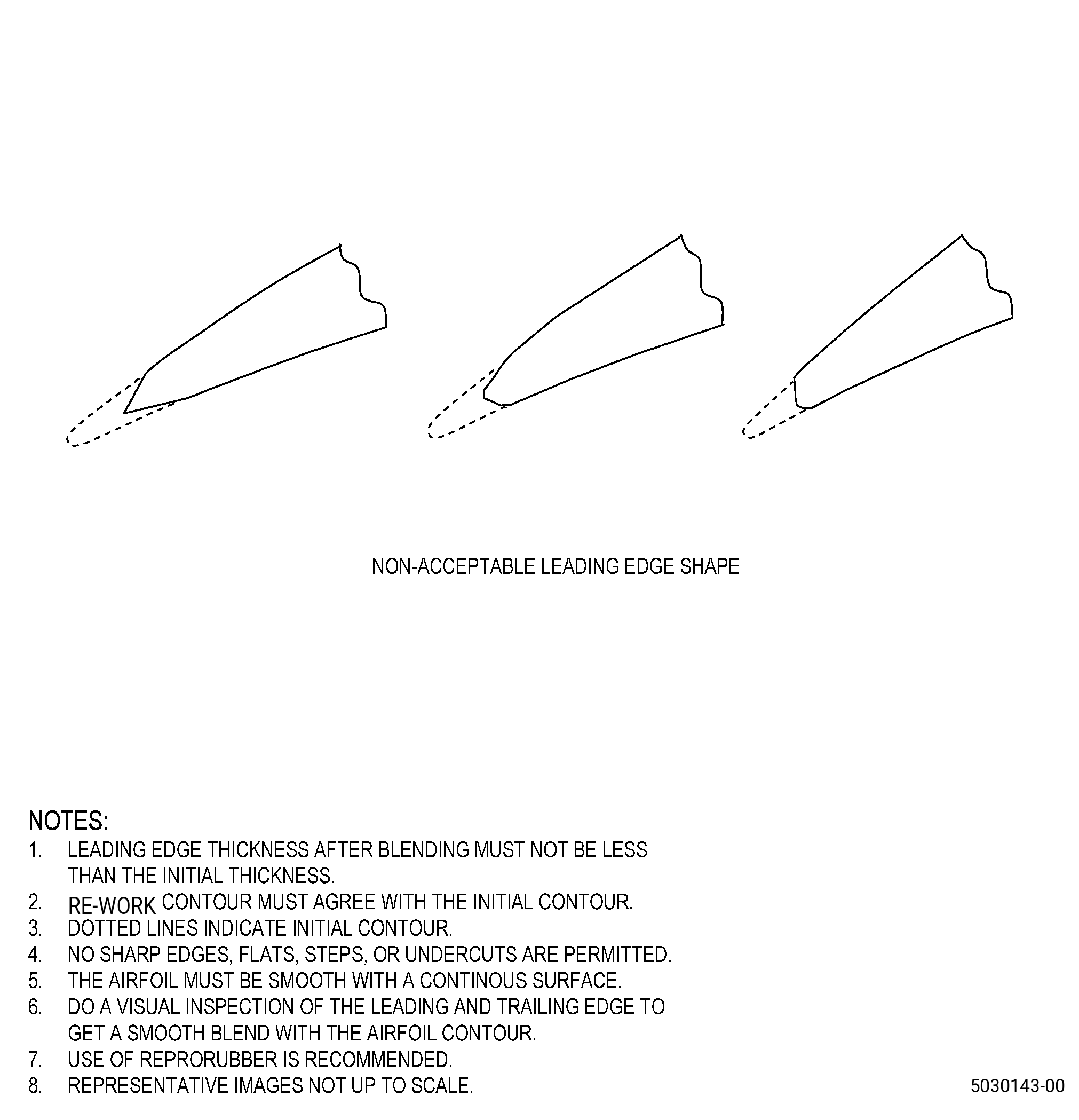
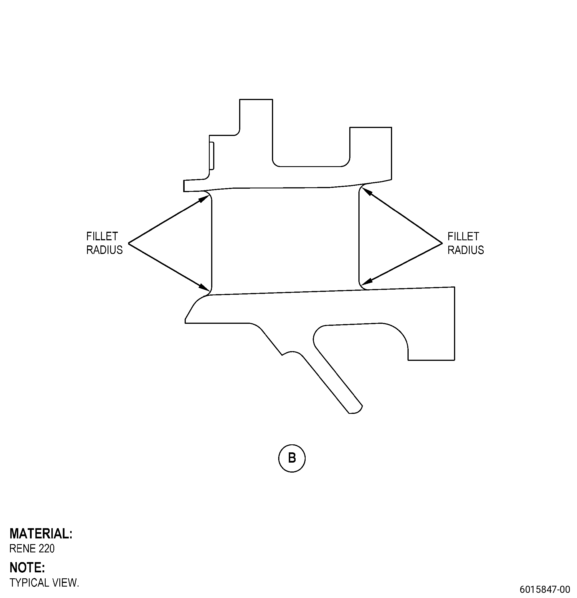
| L. | Blend the OGV welded areas. Refer to TASK 70-42-00-350-002 (BLENDING AND REMOVAL OF HIGH METAL PROCEDURES), Figure 901, Figure 902, and as follows: |
| (1) | Blend the welds smooth to the adjacent contour. You can use Reprorubber or a local tool during this operation. |
| (2) | Sharp edges or flats are not permitted in the edge. |
| (3) | Make sure that there is a smooth transition between the edge and the contour of the vane. |
| Subtask 72-41-20-110-018 |
| M. | Etch the OGV repair area. Refer to TASK 70-24-00-110-033 (ETCHING PROCEDURES FOR FLUORESCENT-PENETRANT INSPECTION), TASK 70-24-01-110-034 (SWAB ETCHING PROCEDURE), and as follows: |
| (1) | Use Class C etchant. |
| Subtask 72-41-20-230-011 |
| N. | Do an inspection of the OGV repair area. Refer to TASK 70-32-00-200-002 (INDIRECT INSPECTION METHODS), TASK 70-32-03-230-002 (SPOT-FLUORESCENT-PENETRANT INSPECTION), and as follows: |
| (1) | Use Class A penetrant. |
| (2) | Refer to TASK 72-41-20-200-801 (72-41-20, INSPECTION 001), for the acceptability limits. |
| Subtask 72-41-20-260-002 |
| O. | Do an inspection of the weld repaired area of the trailing edge fillet radius only. Refer to TASK 70-32-00-200-002 (INDIRECT INSPECTION METHODS), TASK 70-32-05-260-001 (RADIOGRAPHIC INSPECTION), and as follows: |
| (1) | Indications less than 0.030 inch (0.76 mm) are not interpretable. |
| (2) | Indications more than 0.030 inch (0.77 mm) and less than 0.060 inch (1.52 mm) are acceptable if they are non-linear indications. |
| NOTE: |
|
| Subtask 72-41-20-110-019 |
| P. | If necessary, clean the OGV. Refer to TASK 72-41-20-100-801 (72-41-20, CLEANING 001). |
| Subtask 72-41-20-350-054 |
| Q. | If you removed the honeycomb from the OGV in Subtask 72-41-20-350-051 (paragraph 5.E.), install it again. Refer to TASK 72-41-20-300-804 (72-41-20, REPAIR 007). |
| Subtask 72-41-20-370-005 |
| (1) | Deleted. |
| Subtask 72-41-20-110-020 |
| (2) | Deleted. |
| Subtask 72-41-20-350-055 |
| R. | If you did not remove the honeycomb from the OGV, do as follows: |
| Subtask 72-41-20-370-011 |
| (1) | Heat-treat the OGV. Refer to TASK 70-41-00-310-001 (WELDING AND BRAZING PRACTICES), TASK 70-41-03-310-004 (HIGH TEMPERATURE FURNACE BRAZE), and as follows: |
| (a) | Set-up the OGV for heat-treatment. Refer to Subtask 72-41-20-370-010 (paragraph 4.A.), and Figure 903. |
| (b) | Attach four equally-spaced thermocouples to the honeycomb support outer diameter. |
| (c) | Install the OGV in a clean vacuum furnace. |
| (d) | Decrease the vacuum furnace temperature to a vacuum of 5x10⁻⁴ torr (0.5 micron) or better. |
| (e) | Increase the temperature of the OGV to a range of 1700 to 1800°F (927 to 982°C) and as follows: |
| 1 | Keep the temperature of the OGV at a range of 1700 to 1800°F (927 to 982°C) for 10-15 minutes. |
| (f) | Increase the temperature of the OGV to a range of 1900 to 1950°F (1038 to 1065°C) at a rate of not more than 35°F (19°C) for each minute and as follows: |
| 1 | Do not keep the temperature of the OGV at the braze temperature for more than 5 minutes. |
| (g) | Decrease the temperature of the OGV to a range of 1700 to 1800°F (927 to 982°C) at a rate of not more than 35°F (19°C) for each minute and as follows: |
| 1 | Keep the temperature of the OGV at a range of 1700 to 1800°F (927 to 982°C) for 15 minutes maximum. |
| (h) | Decrease the temperature of the OGV to below 1100°F (593°C). |
| (i) | The temperature decrease from 1950°F (1065°C) maximum to below 1100°F (593°C) must be in 30 minutes or less. |
| (j) | The cooling rate below 1100°F (593°C) is not important. |
| Subtask 72-41-20-370-006 |
| (2) | Deleted. |
| Subtask 72-41-20-110-021 |
| (3) | Deleted. |
| Subtask 72-41-20-220-115 |
| S. | Alternative Procedure Available. Do an inspection of the braze joint on the honeycomb seal and the OGV backing strip surface. Refer to TASK 70-33-00-999-001 (SPECIAL INSPECTION PROCEDURES), TASK 70-33-02-220-005 (CAPILLARY INSPECTION OF OPEN FACE HONEYCOMB STRUCTURES), and as follows: |
| (1) | Make sure that the honeycomb ring is fully bonded to its backing surface in 80 percent of the total contact area. |
| (2) | The contact areas of the honeycomb that are not bonded must agree with the limits that follow: |
| (a) | The unbonded area of the honeycomb seal must be less than 10 fully adjacent cells circumferentially and five fully adjacent cells axially. |
| (b) | The unbonded areas must be separated by a minimum of five adjacent bonded cells. |
| (c) | The unbonded areas of the honeycomb seal must not include partial cells. |
| Subtask 72-41-20-220-116 |
| S.A. | Alternative Procedure. Do an inspection of the braze joint on the honeycomb seal and the OGV backing strip surface as follows: |
| (1) | Use a video microscope with 10X magnification. |
| (2) | Refer to the limits in Subtask 72-41-20-220-115 (paragraph 5.S.(1) thru paragraph 5.S.(2)). |
| Subtask 72-41-20-370-012 |
| T. | Heat-treat the OGV in a vacuum furnace. Refer to TASK 70-44-00-800-010 (HEAT TREATING), TASK 70-44-03-370-004 (FURNACE HEAT TREATMENT), Figure 901, and as follows: |
| (1) | Set-up the OGV for heat-treatment. Refer to Subtask 72-41-20-370-010 (paragraph 4.A.). |
| (2) | Attach four equally-spaced thermocouples to the OGV. |
| (3) | Install the OGV setup in a clean vacuum furnace. |
| (4) | Decrease the furnace to a vacuum of 5x10⁻⁴ torr (0.5 micron) or better. |
| * * * ( FOR PART NUMBERS 2303M16G02, 2303M16G04, 2303M16G06, 2763M05G02, 2763M05G03, 2763M05G05, 2763M05G06, 2763M05G09, AND 2763M05G10 ONLY ) |
| (5) | Increase the temperature of the OGV to a range of 1450 to 1500°F (788 to 815°C) and as follows: |
| (a) | Keep the temperature of the OGV to a range of 1450 to 1500°F (788 to 815°C) for 8 hours and plus or minus 10 minutes. |
| (6) | Decrease the temperature of the OGV to a range of 1300 to 1350°F (704 to 732°C) and as follows: |
| (a) | Keep the temperature of the OGV at a range of 1300 to 1350°F (704 to 732°C) for 8 hours and plus or minus 10 minutes. |
| (7) | Decrease the temperature of the OGV to a range of 1125 to 1175°C (607 to 635°C) at a minimum rate of 100°F (38°C) for each hour and as follows: |
| (a) | Keep the temperature of the OGV at a range of 1125 to 1175°F (607 to 635°C) for 8 hours and plus or minus 10 minutes. |
| * * * ( FOR PART NUMBERS 2303M16G05, 2303M16G07, 2303M16G08, 2763M05G04, 2763M05G07, 2763M05G08, AND 2763M05G11 ONLY ) |
| (8) | Increase the temperature of the OGV to a range of 1425 to 1475°F (774 to 802°C) and as follows: |
| (a) | Keep the temperature of the OGV at a range of 1425 to 1475°F (774 to 802°C) for two hours and plus or minus 15 minutes. |
| (9) | Decrease the temperature of the OGV to a range of 1275 to 1325°F (691 to 718°C) and as follows: |
| (a) | Keep the temperature of the OGV at a range of 1275 to 1325°F (691 to 718°C) for 8 hours and plus or minus 15 minutes. |
| (10) | Decrease the temperature of the OGV to a range of 1125 to 1175°F (607 to 635°C) and as follows: |
| (a) | Keep the temperature of the OGV at a range of 1125 to 1175°F (607 to 635°C) for 8 hours and plus or minus 15 minutes. |
| * * * ( FOR ALL PART NUMBERS ) |
| (11) | Decrease the temperature of the OGV to room temperature. |
| Subtask 72-41-20-200-034 |
| U. | Do an inspection of the OGV. Refer to TASK 70-32-00-200-002 (INDIRECT INSPECTION METHODS), TASK 70-32-02-230-001 (FLUORESCENT PENETRANT INSPECTION), and as follows: |
| (1) | Use Class A penetrant. |
| (2) | Refer to TASK 72-41-20-200-801 (72-41-20, INSPECTION 001) for the acceptability limits. |
| Subtask 72-41-20-220-081 |
| V. | Do an inspection of the OGV for T800 thermal spray coating at the W-seal surface N, W-seal surface M, and rabbet diameter C. Refer to Figure 901 and as follows: |
| (1) | Use 10X magnification and white light. |
| (2) | Do not lift or remove the thermal spray coating from the parent metal. |
| (3) | Cracks, blisters, chipping, flaking, spalling, or splatter are not permitted. |
| Subtask 72-41-20-350-056 |
| (4) | If the thermal spray coating is damaged, remove it and replace it. Refer to TASK 72-41-20-300-805 (72-41-20, REPAIR 006). |
| Subtask 72-41-20-350-057 |
| W. | If you removed thermal spray coating from the OGV surface F and diameter G in Subtask 72-41-20-230-009 (paragraph 5.F.), replace it. Refer to TASK 72-41-20-300-807 (72-41-20, REPAIR 005). |
| Subtask 72-41-20-350-058 |
| X. | Install the three cover plates into the OGV. Refer to TASK 72-41-20-300-802 (72-41-20, REPAIR 003). |
| Subtask 72-41-20-350-059 |
| Y. | For part number 2303M16G02 and part number 2303M16G05 install the pins, springs, and leaf seals in the OGV. Refer to TASK 72-41-20-300-801 (72-41-20, REPAIR 001) and Figure 901. |
| Subtask 72-41-20-350-060 |
| Z. | For part numbers 2303M16G04 , 2303M16G06 , 2303M16G07 , 2303M16G08 , 2763M05G02 , 2763M05G03 , 2763M05G04 , 2763M05G05 , 2763M05G06 , 2763M05G07 , 2763M05G08 , 2763M05G09 , 2763M05G10 , and 2763M05G11 install the piston ring in the OGV. Refer to TASK 72-41-00-440-802 (72-41-00, ASSEMBLY 001 - CONFIGURATION 02). |
| Subtask 72-41-20-220-082 |
| AA. | Do a dimensional inspection of the OGV. Refer to TASK 72-41-20-200-801 (72-41-20, INSPECTION 001). |