| GENX-1B CLEANING,INSPECTION,AND REPAIR MANUAL | Dated: 06/05/2024 | |
| CIR 72-41-20 , REPAIR 007 | ||
| STAGE 10 OUTLET GUIDE VANE - REPAIR - REPLACEMENT OF THE COMPRESSOR DISCHARGE PRESSURE HONEYCOMB SEAL | ||
| GENX-1B CLEANING,INSPECTION,AND REPAIR MANUAL | Dated: 06/05/2024 | |
| CIR 72-41-20 , REPAIR 007 | ||
| STAGE 10 OUTLET GUIDE VANE - REPAIR - REPLACEMENT OF THE COMPRESSOR DISCHARGE PRESSURE HONEYCOMB SEAL | ||
| * * * FOR ALL |
| TASK 72-41-20-300-804 |
| 1 . | Repair for the Stage 10 Outlet Guide Vane. |
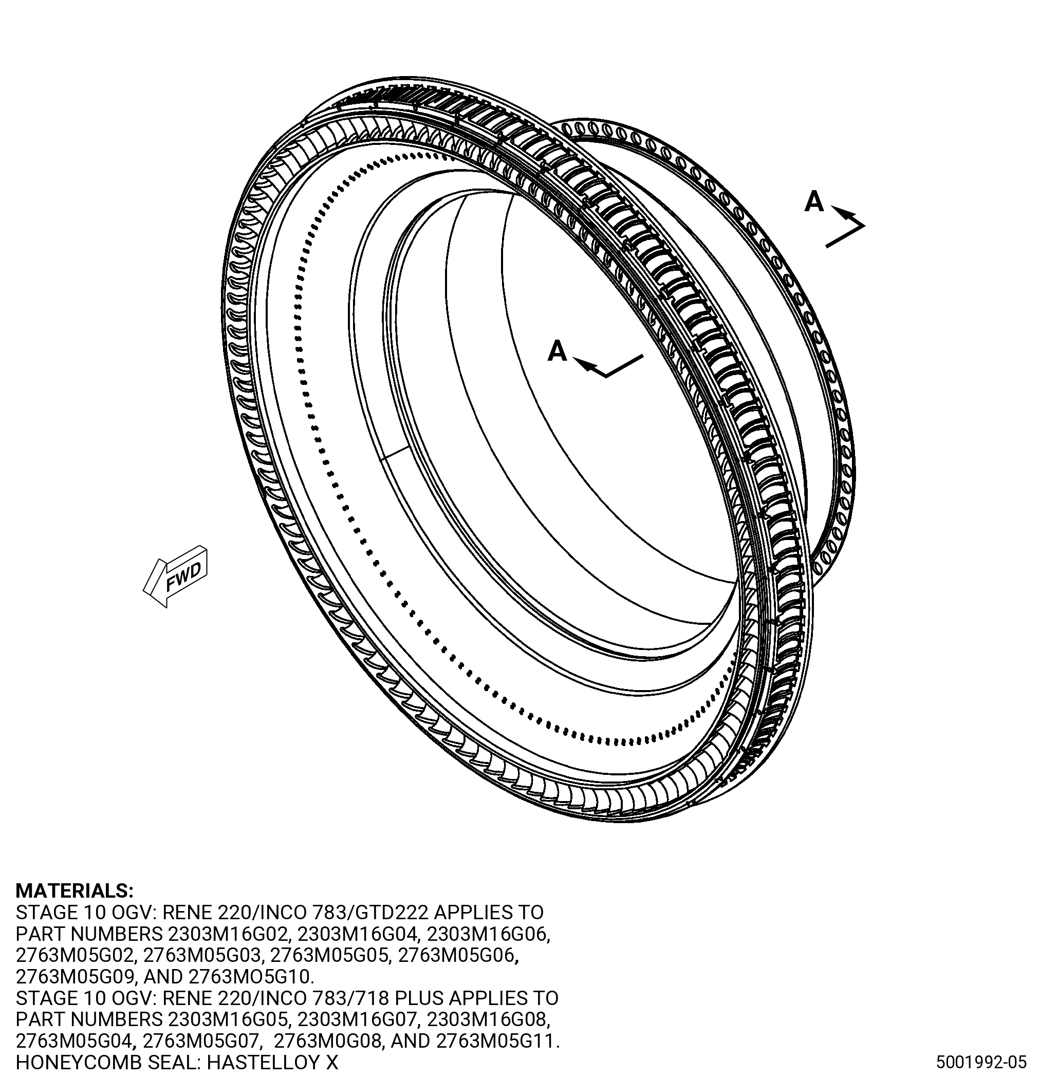
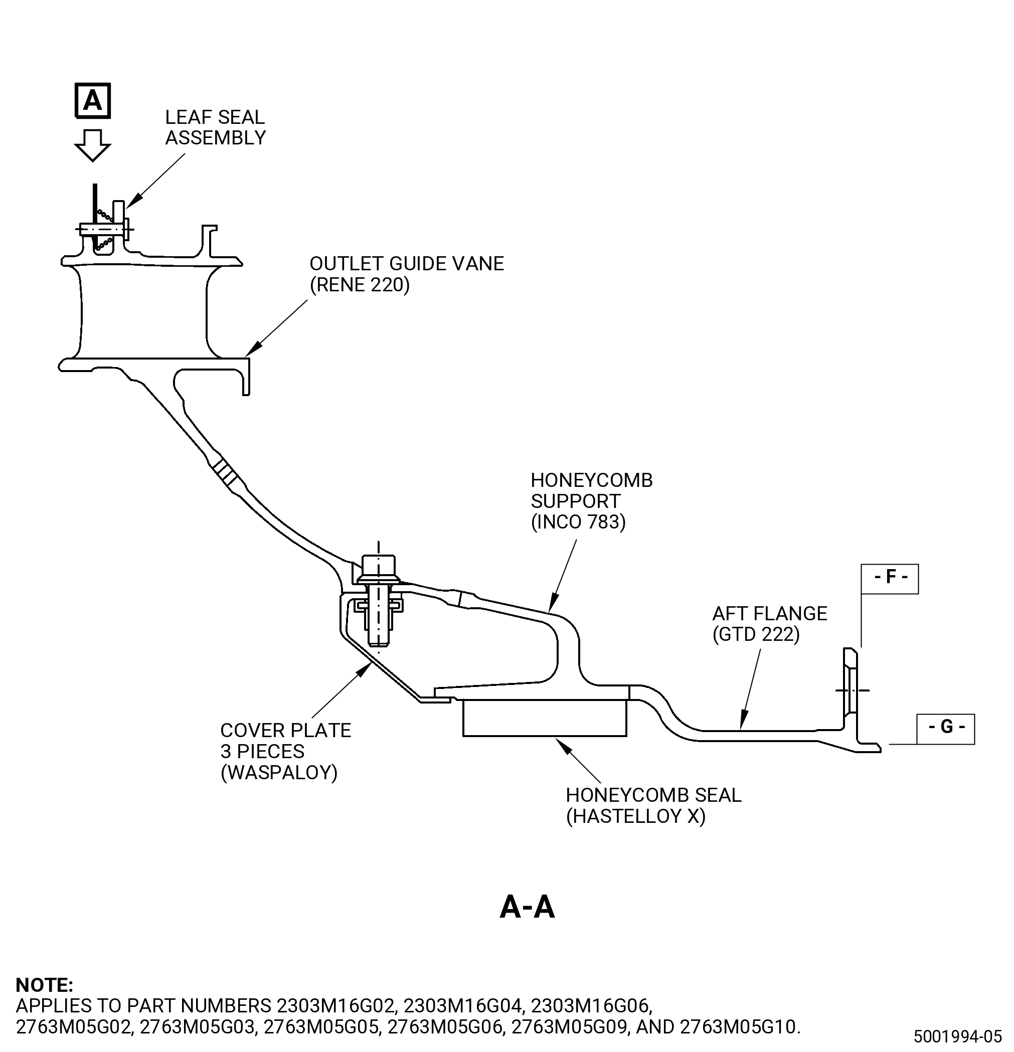
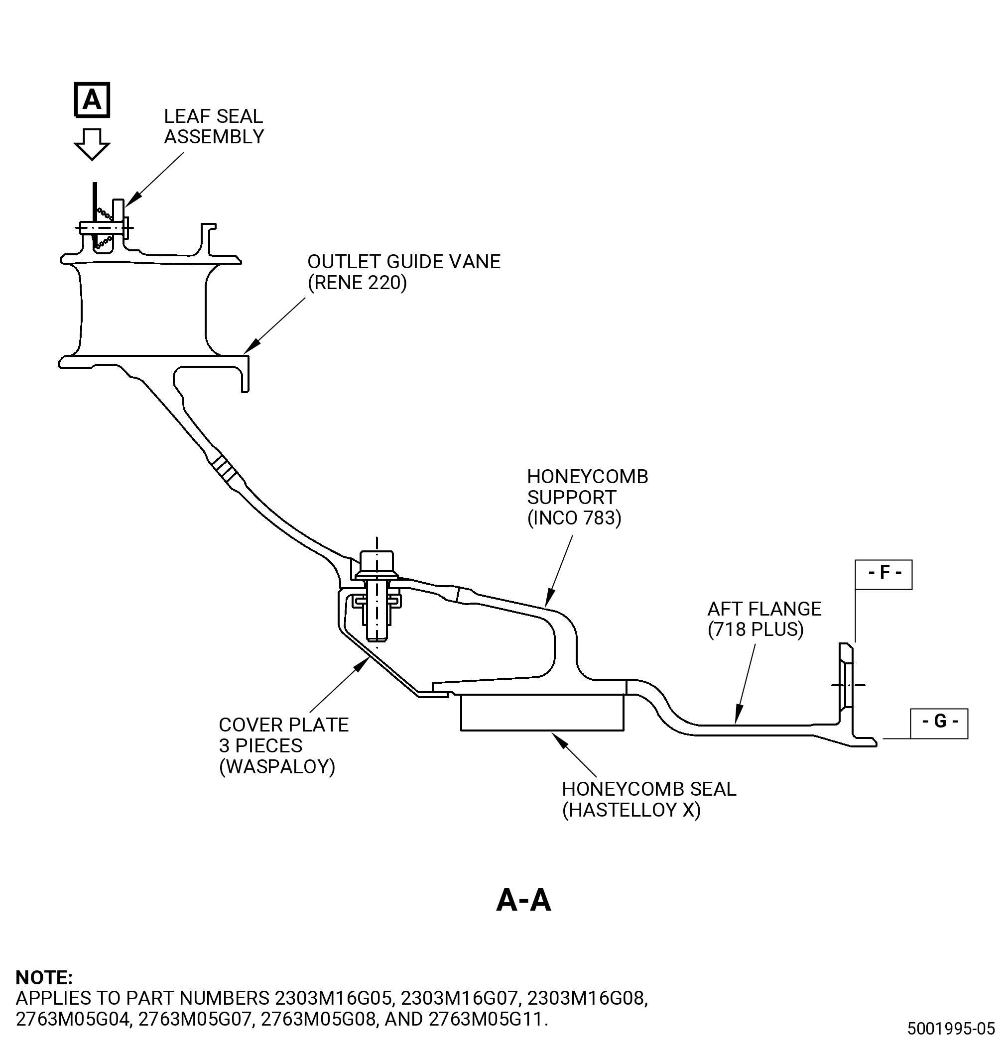
| A. | This procedure gives instructions to repair the stage 10 outlet guide vane (OGV) by removing and replacing the honeycomb seal. Refer to Figure 901. |
| • |
|
| • |
|
| B. | The following maximum repairable limits apply to this repair: |
| NOTE: |
|
| (4) | Visual Inspection. |
| (e) | Do an inspection of the wear coat on surface N for the following. Refer to Figure 802. |
| 1 | Wear-through of the wear coat: |
| Maximum repairable limit: |
|
| 2 | Missing wear coat: |
| Maximum repairable limit: |
|
| (g) | Do an inspection of the CDP seal honeycomb for: |
| 1 | Annular wear grooves: |
| Maximum repairable limit: |
|
| 2 | Cell damage/erosion (does not include the area forward of the forward annular wear groove): |
| Maximum repairable limit: |
|
| 3 | Cell damage/erosion forward of the forward annular wear groove: |
| Maximum repairable limit: |
|
| (k) | Do an inspection of the wear coat on surface M for the following. Refer to Figure 802. |
| 1 | Wear-through of the wear coat: |
| Maximum repairable limit: |
|
| 2 | Missing wear coat: |
| Maximum repairable limit: |
|
| C. | The subsequent table gives a list of the part numbers that are applicable to this repair. All part numbers are applicable to all paragraphs unless specified differently. |
|
||||||||||||||||||||||||||||||||||||||||||||||||||||||||||||||
| D. | Proprietary/Complex Process Statement. |
| (1) | None. |
| 2 . | Tools, Equipment, and Materials. |
| NOTE: |
|
| A. | Tools and Equipment. |
| (1) | Special Tools. None. |
| (2) | Standard Tools and Equipment. None. |
| (3) | Locally Manufactured Tools. |
|
| B. | Consumable Materials. |
| C. | Referenced Procedures. |
|
| D. | Expendable Parts. None. |
| E. | SPD Information. |
| (1) | Locally Manufactured SPD. |
|
| F. | Special Solutions. None. |
| G. | Test Specimens. None. |
| 3 . | Dimensional Information. |
| Subtask 72-41-20-220-050 |
| A. | Refer to Figure 901, Figure 902, and Figure 906 for specified dimensions and locations. |
| NOTE: |
|
| NOTE: |
|
| 4 . | Setup Information. |
| Subtask 72-41-20-350-011 |
| A. | Set-up the OGV for machining as follows: |
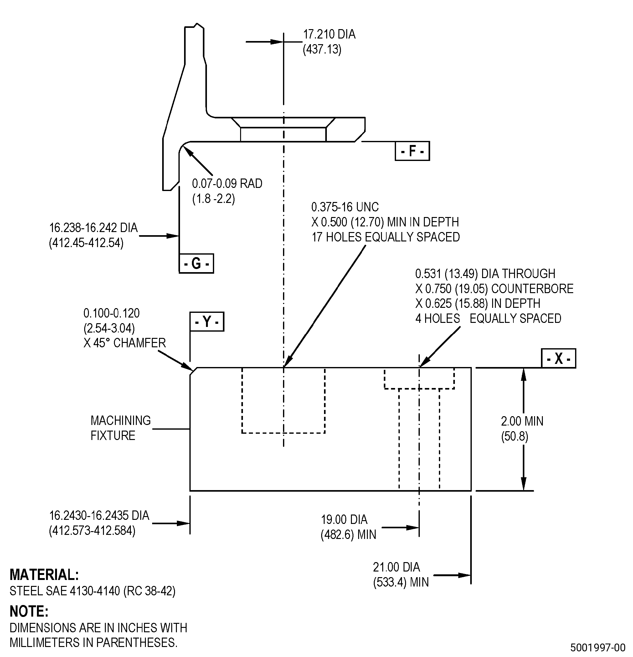
| (1) | If necessary, make the machining fixture. Refer to Figure 903. |
| (2) | Install the machining fixture on the machining table as follows: |
| (a) | Adjust the position of the machining fixture to get the runout of surface X to 0.001 inch (0.02 mm) full indicator reading (FIR) or less as follows: |
| 1 | If necessary, put C10-155 shims between the machining fixture and the machining table to get the necessary runout. |
| (b) | If necessary, adjust the position of the machining fixture to make sure that the runout of diameter Y is 0.001 inch (0.02 mm) FIR or less. |
| (c) | Use four 0.500-13 UNC socket-head cap screws to hold the machining fixture to the machining table and as follows: |
| 1 | Make sure that the runouts of surface X and diameter Y agree with the requirements specified in Subtask 72-41-20-350-011 (paragraph 4.A.(2)(a)) and Subtask 72-41-20-350-011 (paragraph 4.A.(2)(b)). |
| (3) | Install the OGV onto the machining fixture as follows: |
| NOTE: |
|
| (a) | Put the OGV onto the machining fixture and align the boltholes in the flange with the 17 threaded holes in the machining fixture. |
| (b) | Attach the OGV to the machining fixture with 17 0.375-16 UNC bolts or screws. |
| (4) | Make sure that the OGV is installed flat on the machining fixture as follows: |
| (a) | The maximum permitted clearance between surface X of the machining fixture and surface F of the OGV is 0.002 inch (0.05 mm). |
| Subtask 72-41-20-350-012 |
| B. | Set-up the OGV for heat-treating. Refer to Figure 904 and as follows: |
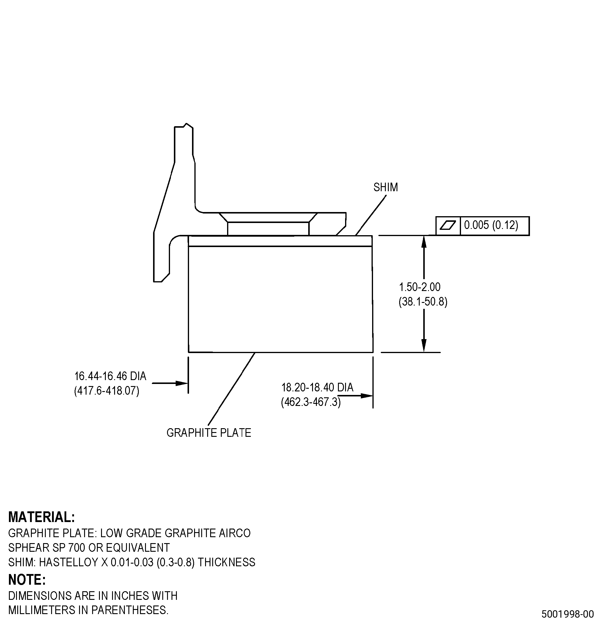
| (1) | If necessary, make the heat-treat fixture. Refer to Figure 904. |
| (2) | Put the graphite plate on a furnace grid. |
| (3) | Put C10-155 shims on top of the graphite plate. |
| (4) | Put the OGV onto the graphite plate and C10-155 shims as follows: |
| (a) | Make sure that the position of the OGV is aft end down. |
| 5 . | Procedure. |
| Subtask 72-41-20-300-013 |
| A. | For P/N 2303M16G02 and 2303M16G05 , remove the pins, springs, and leaf seals from the OGV. Refer to TASK 72-41-20-300-801 (72-41-20, REPAIR 001). |
| Subtask 72-41-20-040-001 |
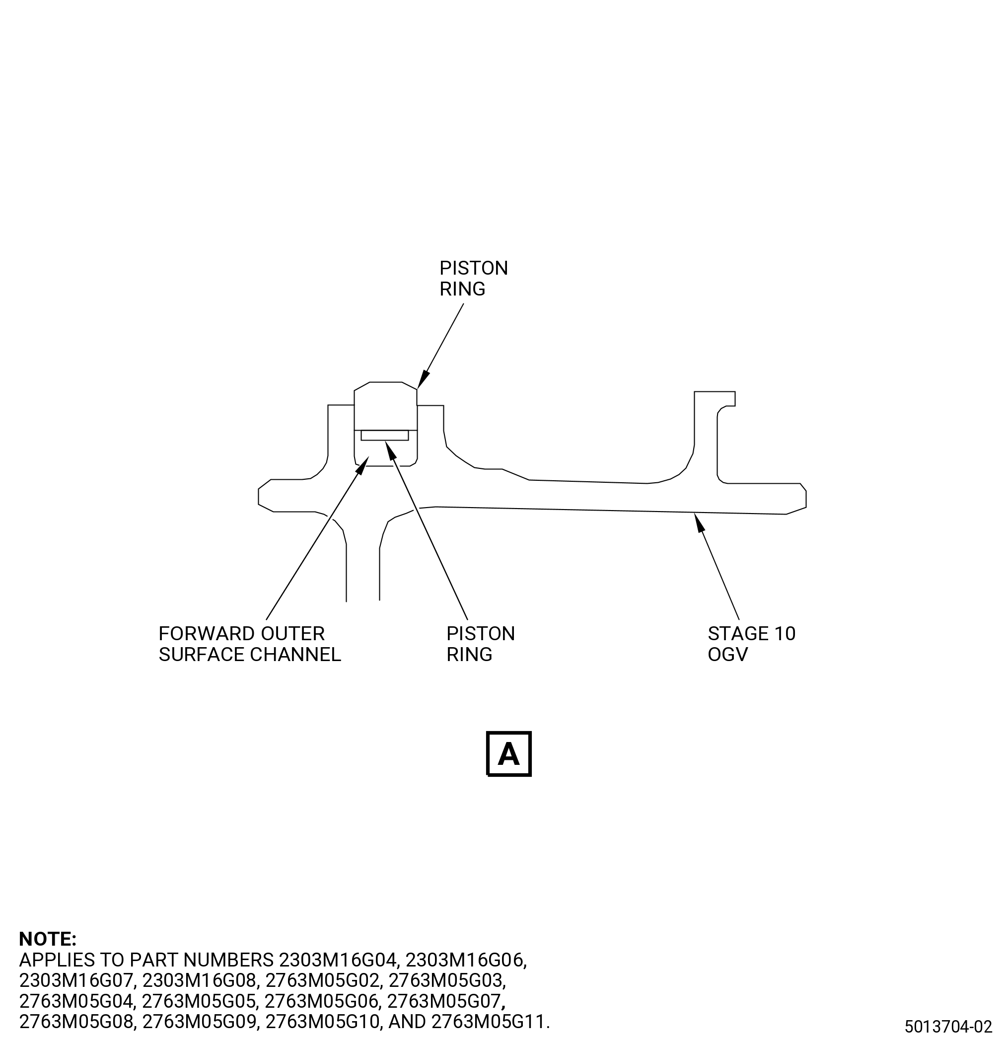
| A.A. | For part numbers 2303M16G04 , 2303M16G06 , 2303M16G07 , 2303M16G08 , 2763M05G02 , 2763M05G03 , 2763M05G04 , 2763M05G05 , 2763M05G06 , 2763M05G07 , 2763M05G08 , 2763M05G09 , 2763M05G10 , and 2763M05G11 remove the piston ring. Refer to TASK 72-41-00-040-802 (72-41-00, DISASSEMBLY 001, CONFIGURATION 02) and Figure 901. |
| Subtask 72-41-20-300-014 |
| B. | Remove the three cover plates from the OGV. Refer to TASK 72-41-20-300-802 (72-41-20, REPAIR 003). |
| Subtask 72-41-20-800-003 |
| CAUTION: |
|
| C. | Machine the OGV to remove the honeycomb seal from the inner diameter (ID) surface, diameter AG. Refer to TASK 70-00-03-800-004 (MACHINING DATA) and as follows: |
| (1) | Set-up the OGV for machining. Refer to Subtask 72-41-20-350-011 (paragraph 4.A.), Setup Information. |
| (2) | Machine the honeycomb seal from the ID surface of the OGV until you can see the parent metal. Refer to Figure 902 and as follows: |
| (a) | Do not machine into the parent metal of the OGV. |
| (3) | Machine the ID surface of the OGV until the contour is smooth and free of honeycomb stubble and honeycomb dimples. Refer to Figure 905 and as follows: |
| NOTE: |
|
| (a) | If necessary, you can move the honeycomb seal and the machining fixture on the machining table to remove local areas of remaining honeycomb stubble and dimples. |
| Subtask 72-41-20-350-013 |
| (4) | If necessary, blend the OGV to remove local areas of remaining honeycomb stubble and dimples from the ID surface. Refer to TASK 70-42-00-350-002 (BLENDING AND REMOVAL OF HIGH METAL PROCEDURES), Figure 905, and as follows: |
| (a) | Use C10-121 abrasive paper. |
| (b) | Blend the ID surfaces of the OGV in a circumferential direction and as follows: |
| 1 | The contour variations after you blend the OGV must be 0.002 inch (0.05 mm) or less for each 1.00 inch (25.4 mm). |
| Subtask 72-41-20-220-051 |
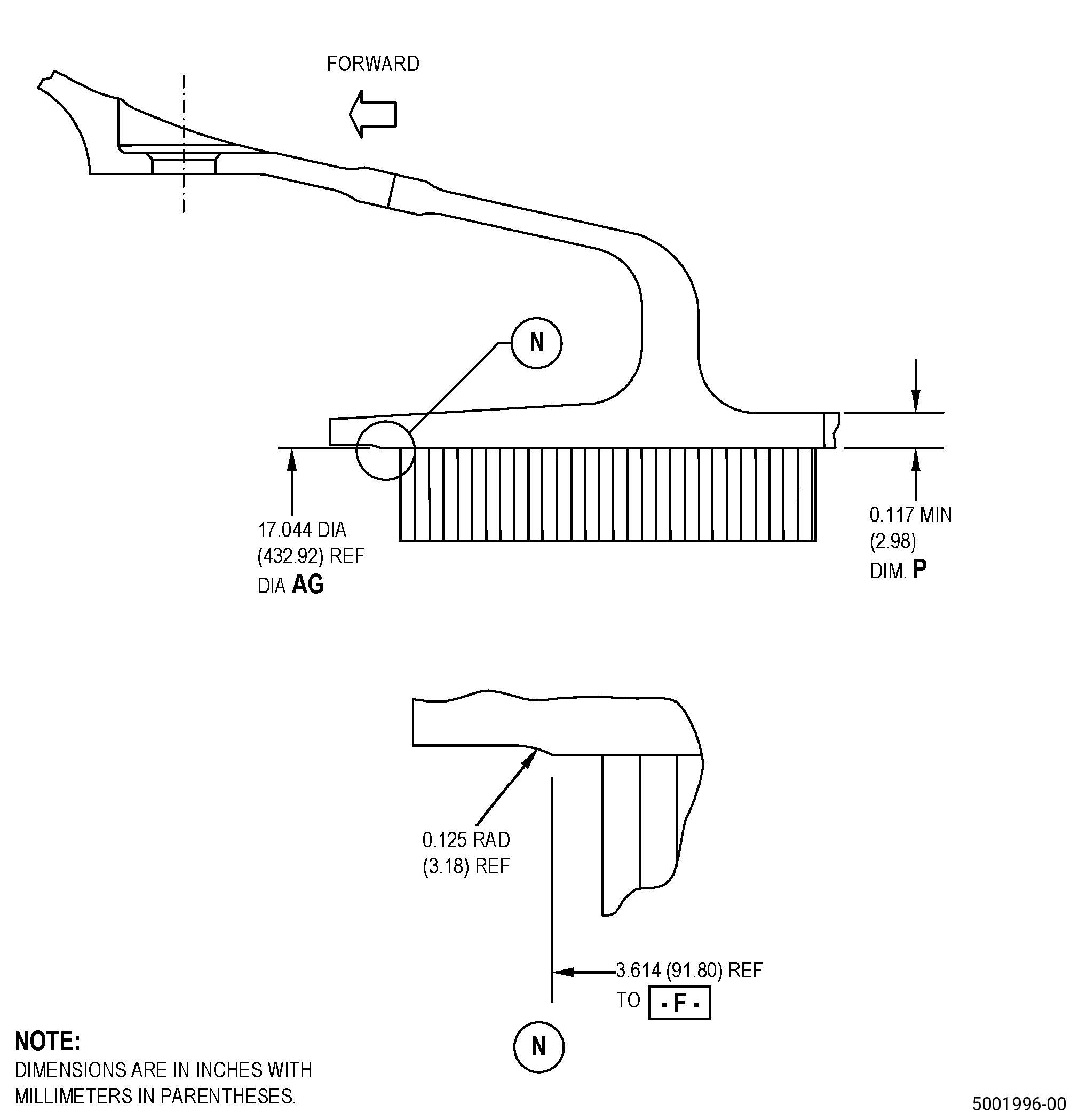
| (5) | Do an inspection of the OGV honeycomb support. Refer to Figure 902 and as follows: |
| (a) | Make sure that dimension P is in the limits. |
| (6) | Remove the OGV from the machining fixture. |
| Subtask 72-41-20-110-008 |
| D. | Etch the machined and blended diameter AG of the OGV honeycomb backing strip. Refer to TASK 70-24-00-110-033 (ETCHING PROCEDURES FOR FLUORESCENT-PENETRANT INSPECTION), TASK 70-24-01-110-034 (SWAB ETCHING PROCEDURE), Figure 902, and as follows: |
| (1) | Use Class C etchant. |
| Subtask 72-41-20-200-024 |
| E. | Do an inspection of the machined and blended diameter AG of the OGV honeycomb backing strip. Refer to TASK 70-32-00-200-002 (INDIRECT INSPECTION METHODS), TASK 70-32-03-230-002 (SPOT-FLUORESCENT-PENETRANT INSPECTION), and as follows: |
| (1) | Use Class A penetrant. |
| (2) | Refer to TASK 70-31-02-220-003 (ACCEPTABILITY LIMITS FOR FLUORESCENT-PENETRANT INSPECTION) and as follows: |
| (a) | Use Class A limits. |
| Subtask 72-41-20-100-009 |
| F. | Clean the machined and blended areas of the OGV honeycomb backing strip. Refer to TASK 70-21-00-110-051 (CHEMICAL CLEANING), TASK 70-21-03-160-001 (CLEANING METHOD NO. 3 - STEAM CLEANING), and as follows: |
| WARNING: |
|
| (1) | Lightly sand the OGV with C10-121 abrasive paper to remove surface oxides on the surface of diameter AG. |
| Subtask 72-41-20-330-001 |
| WARNING: |
|
| G. | Optional Procedure. Apply AMS 2403 nickel plate coating to the OGV diameter AG surface. Refer to Figure 902 and as follows: |
| NOTE: |
|
| (1) | Apply C10-067 masking tape to all the OGV adjacent surfaces. |
| (2) | Apply nickel plate (AMS 2403) coating to a thickness of 0.0002-0.0010 inch (0.005-0.025 mm) and as follows: |
| (a) | Overplating is not permitted. |
| (3) | Remove the C10-067 masking tape from the OGV. |
| Subtask 72-41-20-350-014 |
| H. | Make the replacement honeycomb seal. Refer to Figure 907 and as follows: |
| (1) | There must be an interference fit of approximately 0.050 inch (1.27 mm) between the replacement honeycomb seal and diameter AG for the backing strip surface diameter AG. |
| (2) | Make sure that there is sufficient material on the replacement honeycomb seal to finish-grind the replacement honeycomb seal diameter. |
| (3) | After you complete the brazing and finish-grind operations, all the replacement honeycomb seal dimensions must be in the limits. |
| Subtask 72-41-20-110-009 |
| I. | Clean the replacement honeycomb seal and the backing strip surface diameter AG as follows: |
| (1) | Clean the replacement honeycomb seal. Refer to TASK 70-21-00-110-051 (CHEMICAL CLEANING) and TASK 70-21-23-110-053 (CLEANING METHOD NO. 23 - HAND-WIPE DEGREASING). |
| (2) | Clean the OGV diameter AG surface as follows: |
| WARNING: |
|
| (a) | Use a C10-182 cleaning cloth moist with C04-035 isopropyl alcohol. |
| (b) | Clean the OGV diameter AG surface until there is no remaining material or lint on the C10-182 cleaning cloth. |
| Subtask 72-41-20-350-015 |
| CAUTION: |
|
| J. | Trial-install the replacement honeycomb seal onto the OGV. Refer to Figure 906, Figure 907, and as follows: |
| (1) | Use clean C10-139 gloves when you touch the cleaned OGV and the replacement honeycomb seal. |
| (2) | Put the replacement honeycomb seal into position in the OGV. |
| (3) | When you fully install the replacement honeycomb seal, the interference fit must be as follows: |
| (a) | A firm axial push is necessary to move the honeycomb seal inside the ID of the honeycomb support. |
| (b) | If you move the honeycomb seal with light finger pressure, choose a different replacement honeycomb seal. |
| Subtask 72-41-20-310-004 |
| K. | Tack-weld the replacement honeycomb seal to the backing strip surface diameter AG of the OGV. Refer to TASK 70-41-00-310-001 (WELDING AND BRAZING PRACTICES), TASK 70-41-04-310-005 (RESISTANCE WELDING - SPOT, SEAM, AND PROJECTION), Figure 906, and as follows: |
| NOTE: |
|
| (1) | Adjust the OGV or the electrode until each weld makes an overlap with the weld done before by approximately 25 percent of the electrode width. |
| (2) | Adjust the welder settings as necessary to decrease burned honeycomb seal material to a minimum and as follows: |
| (a) | Make sure that you remove all the burned honeycomb seal areas when you finish machining the honeycomb seal. |
| (b) | Replace the burned honeycomb that is not removed by the final machining process. |
| Subtask 72-41-20-220-052 |
| (3) | Make sure that all the replacement honeycomb seal is tightly attached to the OGV and as follows: |
| (a) | Use a 4X or 5X magnification and do an inspection of the outer ribbon of the replacement honeycomb seal. |
| (b) | Make sure that there are no clearances between the replacement honeycomb seal and the OGV. |
| Subtask 72-41-20-310-005 |
| (4) | If there is a clearance, weld the replacement honeycomb seal to the OGV again to remove clearances. |
| Subtask 72-41-20-220-053 |
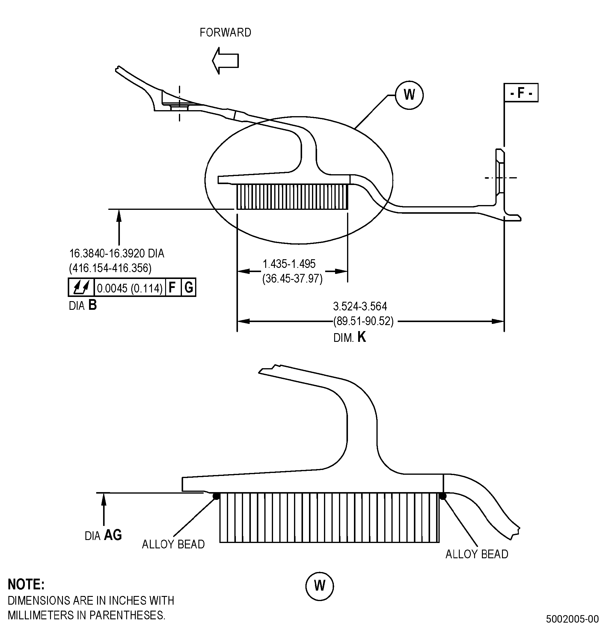
| (5) | Do an inspection of the OGV dimension K to make sure that the replacement honeycomb seal is in the correct position. |
| Subtask 72-41-20-220-054 |
| L. | Do a visual inspection of all the OGV areas of electrical ground contact for burning or pitting and do as follows: |
| (1) | Blend all pits that are 0.030 inch (0.76 mm) or less in diameter and 0.005 inch (0.13 mm) or less in depth. |
| (2) | Pits that are more than 0.030 inch (0.76 mm) in diameter and more than 0.005 inch (0.13 mm) in depth are not permitted. |
| Subtask 72-41-20-310-006 |
| M. | Prepare the replacement honeycomb seal and the OGV for brazing. Refer to Figure 906, and as follows: |
| NOTE: |
|
| (1) | Apply C06-014 braze alloy to the replacement honeycomb seal as follows: |
| (a) | Equally apply approximately 0.07 ounces (2.0 g) of C06-014 braze alloy for each 1.0 sq in. (645.1 sq mm) of honeycomb ring into the honeycomb cells and do as follows: |
| Subtask 72-41-20-220-055 |
| 1 | Do a visual inspection of the filled cells to make sure that there is the correct quantity of C06-014 braze alloy in the honeycomb cells. |
| Subtask 72-41-20-350-016 |
| WARNING: |
|
| CAUTION: |
|
| (2) | If necessary, spray C01-034 acrylic cement into the honeycomb cells to hold the C06-014 braze alloy in the replacement honeycomb seal. |
| (3) | Remove the braze alloy from all surfaces adjacent to the replacement honeycomb seal on the OGV before you put the parts in the furnace. |
| (4) | Mix a quantity of slurry of 5-10 percent of C06-024 nickel braze alloy with 90-95 percent of C06-014 braze alloy and C06-019 binder to make a braze fillet and as follows: |
| (a) | Apply external braze fillet in an approximately 0.06 inch (1.5 mm) diameter bead 360 degrees around the forward edges and aft edges of the replacement honeycomb seal to make an alloy bead. |
| WARNING: |
|
| (5) | If necessary, apply C10-020 braze stop-off to the honeycomb backing strip surface to prevent unwanted braze flow on the OGV and as follows: |
| (a) | Make sure that the C10-020 braze stop-off does not touch the replacement honeycomb seal. |
| Subtask 72-41-20-310-007 |
| CAUTION: |
|
| N. | Braze the OGV and the replacement honeycomb seal. Refer to TASK 70-41-00-310-001 (WELDING AND BRAZING PRACTICES), TASK 70-41-03-310-004 (HIGH TEMPERATURE FURNACE BRAZE), and as follows: |
| (1) | Set-up the OGV for heat-treating. Refer to Subtask 72-41-20-350-012 (paragraph 4.B.), Setup Information. |
| (2) | Attach four equally spaced thermocouples to the honeycomb support outside diameter. |
| (3) | Install the OGV in a clean vacuum furnace. |
| (4) | Decrease the vacuum furnace temperature to a vacuum of 5x10⁻⁴ torr (0.5 micron) or better. |
| (5) | Increase the temperature of the OGV to a range of 1700 to 1800°F (927 to 982°C) and as follows: |
| (a) | Keep the temperature of the OGV at a range of 1700 to 1800°F (927 to 982°C) for 10-15 minutes. |
| (6) | Increase the temperature of the OGV to a range of 1900 to 1950°F (1038 to 1065°C) at a rate of not more than 35°F (19°C) for each minute and as follows: |
| (a) | Keep the temperature of the OGV at the braze temperature until the braze alloy gets wet. |
| (b) | Do not keep the temperature of the OGV at the braze temperature for more than 5 minutes. |
| (7) | Decrease the temperature of the OGV to a range of 1700 to 1800°F (927 to 982°C) at a rate of not more than 35°F (19°C) for each minute and as follows: |
| (a) | Keep the temperature of the OGV at a range of 1700 to 1800°F (927 to 982°C) for 15 minutes maximum. |
| (8) | Decrease the temperature of the OGV to below 1100°F (593°C). |
| (9) | The temperature decrease from 1950°F (1065°C) maximum to below 1100°F (593°C) must be in 30 minutes or less. |
| (10) | The cooling rate below 1100°F (593°C) is not important. |
| Subtask 72-41-20-200-025 |
| O. | Alternative Procedure Available. Do an inspection of the braze joint on the replacement honeycomb seal and the OGV backing strip surface. Refer to TASK 70-33-00-999-001 (SPECIAL INSPECTION PROCEDURES), TASK 70-33-02-220-005 (CAPILLARY INSPECTION OF OPEN FACE HONEYCOMB STRUCTURES), and as follows: |
| (1) | Make sure that the honeycomb ring is fully bonded to its backing surface in 80 percent of the total contact area. |
| (2) | The contact area(s) of honeycomb that is not bonded must agree with the limits that follow: |
| (a) | The unbonded area of the replacement honeycomb seal must be less than 10 fully adjacent cells circumferentially and five fully adjacent cells axially. |
| (b) | Unbonded areas must be separated by a minimum of five adjacent bonded cells. |
| (c) | The unbonded area of the replacement honeycomb seal must not include partial cells. |
| Subtask 72-41-20-200-026 |
| O.A. | Alternative Procedure. Do an inspection of the braze joint on the honeycomb seal and the OGV backing strip surface as follows: |
| (1) | Use a video microscope with 10X magnification. |
| (2) | Refer to the limits in Subtask 72-41-20-200-025 (paragraph 5.O.(1)) thru Subtask 72-41-20-200-025 (paragraph 5.O.(2)). |
| Subtask 72-41-20-300-015 |
| P. | If necessary, repair the OGV braze areas that do not agree with the requirements in Subtask 72-41-20-200-025 (paragraph 5.O.) or Subtask 72-41-20-200-026 (paragraph 5.O.A.) as follows: |
| (1) | Apply C06-014 braze alloy to the local area where repair is necessary and as follows: |
| (a) | Apply C06-014 braze alloy in powder form equally where repair is necessary as follows: |
| 1 | Apply approximately 2-2.5 grams for each 1.0 sq in. (645.1 sq mm) of repair area. |
| WARNING: |
|
| (b) | Lightly spray C01-034 acrylic cement into the alloyed cells and let the cement dry. |
| (2) | Braze the OGV repair area. Refer to Subtask 72-41-20-300-015 (paragraph 5.P.) and as follows: |
| (a) | The total time at the braze temperature for all braze cycles cannot be more than 30 minutes. |
| (3) | Do an inspection of the OGV repair area. Refer to Subtask 72-41-20-200-025 (paragraph 5.O.). |
| * * * PRE SB 72-0046( Deleted ) |
| Subtask 72-41-20-300-016 |
| Q. | Heat-treat the OGV in a vacuum furnace. Refer to TASK 70-44-00-800-010 (HEAT TREATING), TASK 70-44-03-370-004 (FURNACE HEAT TREATMENT), Figure 901, and as follows: |
| (1) | Set-up the OGV for heat treating. Refer to Subtask 72-41-20-350-012 (paragraph 4.B.), Setup Information. |
| (2) | Attach four equally spaced thermocouples to the OGV. |
| (3) | Install the OGV setup in a clean vacuum furnace. |
| (4) | Decrease the furnace to a vacuum of 5x10⁻⁴ torr (0.5 micron) or better. |
| * * * FOR PART NUMBERS 2303M16G02, 2303M16G04, 2303M16G06, 2763M05G02, 2763M05G03, 2763M05G05, 2763M05G06, 2763M05G09 AND 2763M05G10 ONLY:( ) |
| (5) | Increase the temperature of the OGV to a range of 1450 to 1500°F (788 to 815°C) and as follows: |
| (a) | Keep the temperature of the OGV at a range of 1450 to 1500°F (788 to 815°C) for 8 hours and plus or minus 10 minutes. |
| (6) | Decrease the temperature of the OGV to a range of 1300 to 1350°F (705 to 732°C) and as follows: |
| (a) | Keep the temperature of the OGV at a range of 1300 to 1350°F (705 to 732°C) for 8 hours and plus or minus 10 minutes. |
| (7) | Decrease the temperature of the OGV to a range of 1125 to 1175°F (608 to 635°C) at a minimum rate of 100°F (38°C) for each hour and as follows: |
| (a) | Keep the temperature of the OGV at a range of 1125 to 1175°F (608 to 635°C) for 8 hours and plus or minus 10 minutes. |
| (8) | Deleted. |
| * * * END PRE SB 72-0046( Deleted ) |
| * * * SB 72-0046( Deleted ) |
| Subtask 72-41-20-300-017 |
| Q.A. | Deleted. |
| (1) | Deleted. |
| (2) | Deleted. |
| (3) | Deleted. |
| (4) | Deleted. |
| * * * FOR PART NUMBERS 2303M16G05, 2303M16G07, 2303M16G08, 2763M05G04, 2763M05G07, 2763M05G08, AND 2763M05G11 ONLY: |
| (5) | Increase the temperature of the OGV to a range of 1425 to 1475°F (774 to 801°C) and as follows: |
| (a) | Keep the temperature of the OGV at a range of 1425 to 1475°F (774 to 801°C) for 2 hours and plus or minus 15 minutes. |
| (6) | Decrease the temperature of the OGV to a range of 1275 to 1325°F (691 to 718°C) and as follows: |
| (a) | Keep the temperature of the OGV at a range of 1275 to 1325°F (691 to 718°C) for 8 hours and plus or minus 15 minutes. |
| (7) | Decrease the temperature of the OGV to a range of 1125 to 1175°F (608 to 635°C) and as follows: |
| (a) | Keep the temperature of the OGV at a range of 1125 to 1175°F (608 to 635°C) for 8 hours and plus or minus 15 minutes. |
| * * * FOR ALL PART NUMBERS: |
| (8) | Decrease the temperature of the OGV to room temperature. |
| * * * END SB 72-0046( Deleted ) |
| Subtask 72-41-20-200-027 |
| R. | Do an inspection of the OGV. Refer to TASK 70-32-00-200-002 (INDIRECT INSPECTION METHODS), TASK 70-32-02-230-001 (FLUORESCENT PENETRANT INSPECTION), and as follows: |
| (1) | Use Class A penetrant. |
| (2) | Use a spray or brush application only. |
| (3) | Refer to TASK 70-31-02-220-003 (ACCEPTABILITY LIMITS FOR FLUORESCENT-PENETRANT INSPECTION) and as follows: |
| (a) | Use Class A limits. |
| (4) | If necessary, clean the OGV. Refer to TASK 72-41-20-100-801 (72-41-20, CLEANING 001). |
| Subtask 72-41-20-200-028 |
| S. | Do a dimensional inspection of the OGV. Refer to TASK 72-41-20-200-801 (72-41-20, INSPECTION 001). |
| Subtask 72-41-20-200-029 |
| T. | Do an inspection of the T800 wear coat on the OGV diameter C, surface M, and surface N for missing coating. Refer to TASK 72-41-20-200-801 (72-41-20, INSPECTION 001). |
| Subtask 72-41-20-320-002 |
| U. | Machine the honeycomb seal diameter B. Refer to TASK 70-00-03-800-004 (MACHINING DATA), Figure 906, and as follows: |
| NOTE: |
|
| (1) | Set-up the OGV for machining. Refer to Subtask 72-41-20-350-011 (paragraph 4.A.), Setup information. |
| (2) | Finish-machine the honeycomb seal diameter B. Refer to TASK 70-31-05-220-001 (ENGINE PART SURFACE INTEGRITY ACCEPTABILITY LIMITS FOR NONTRADITIONAL MACHINED SURFACES) and to the limits that follow: |
| (a) | The average recast layer permitted on the honeycomb seal surfaces is 0.002 inch (0.05 mm) or less. |
| (b) | The maximum recast layer permitted on the honeycomb seal surface is 0.004 inch (0.10 mm). |
| (c) | Micro-cracks are permitted in the recast layer only. |
| (d) | The maximum intergranular attack permitted on the honeycomb surface is 0.0015 inch (0.038 mm) or less. |
| (e) | Surface finish requirements do not apply to the machined honeycomb seal surfaces. |
| (f) | Redeposited material inside of the honeycomb cells is not permitted, unless it is as follows: |
| 1 | Material that is not more than 0.002 inch (0.05 mm) built-up and is as follows: |
| a | Perpendicular to the cell wall. |
| b | In the top 25 percent of the finished machined cell height. |
| (g) | Redeposited material that is on the surface adjacent to the honeycomb seal is not permitted. |
| (3) | Do a dimensional inspection of the honeycomb diameter and honeycomb runout while the OGV is in the fixture. |
| (4) | Remove the OGV seal from the machining fixture. |
| Subtask 72-41-20-100-010 |
| V. | Clean the OGV. Refer to TASK 72-41-20-100-801 (72-41-20, CLEANING 001). |
| Subtask 72-41-20-220-056 |
| W. | Do a visual inspection of the honeycomb seal for cells filled with remaining braze material as follows: |
| (1) | No filled cells are permitted unless they agree with the conditions that follow: |
| (a) | All cells accept a pin that measures 0.010 inch (0.25 mm) in diameter and 0.250 inch (6.35 mm) in depth. |
| (b) | Filled cells are permitted in the forward end partial cell area or aft end partial cell area. |
| (c) | If necessary, rework filled cells by EDM or with a jeweler's drill to make them agree with the limits as follows: |
| 1 | No more than 2 percent of the honeycomb cells are reworked in a circumferential row. |
| 2 | Reworked cells must accept a pin that measures 0.010 inch (0.25 mm) in diameter and 0.250 inch (6.35 mm) in depth. |
| Subtask 72-41-20-100-011 |
| 3 | Clean the OGV. Refer to TASK 72-41-20-100-801 (72-41-20, CLEANING 001). |
| Subtask 72-41-20-300-018 |
| X. | Install the three cover plates onto the OGV. Refer to TASK 72-41-20-300-802 (72-41-20, REPAIR 003). |
| Subtask 72-41-20-300-019 |
| Y. | For P/N 2303M16G02 and 2303M16G05 , install the pins, springs, and leaf seals to the OGV. Refer to TASK 72-41-20-300-801 (72-41-20, REPAIR 001). |
| Subtask 72-41-20-440-006 |
| Y.A. | For part numbers 2303M16G04 , 2303M16G06 , 2303M16G07 , 2303M16G08 , 2763M05G02 , 2763M05G03 , 2763M05G04 , 2763M05G05 , 2763M05G06 , 2763M05G07 , 2763M05G08 , 2763M05G09 , 2763M05G10 , and 2763M05G11 install the piston ring. Refer to TASK 72-41-00-440-802 (72-41-00, ASSEMBLY 001, CONFIGURATION 02). |