| GENX-1B CLEANING,INSPECTION,AND REPAIR MANUAL | Dated: 06/05/2024 | |
| CIR 72-41-20 , REPAIR 005 | ||
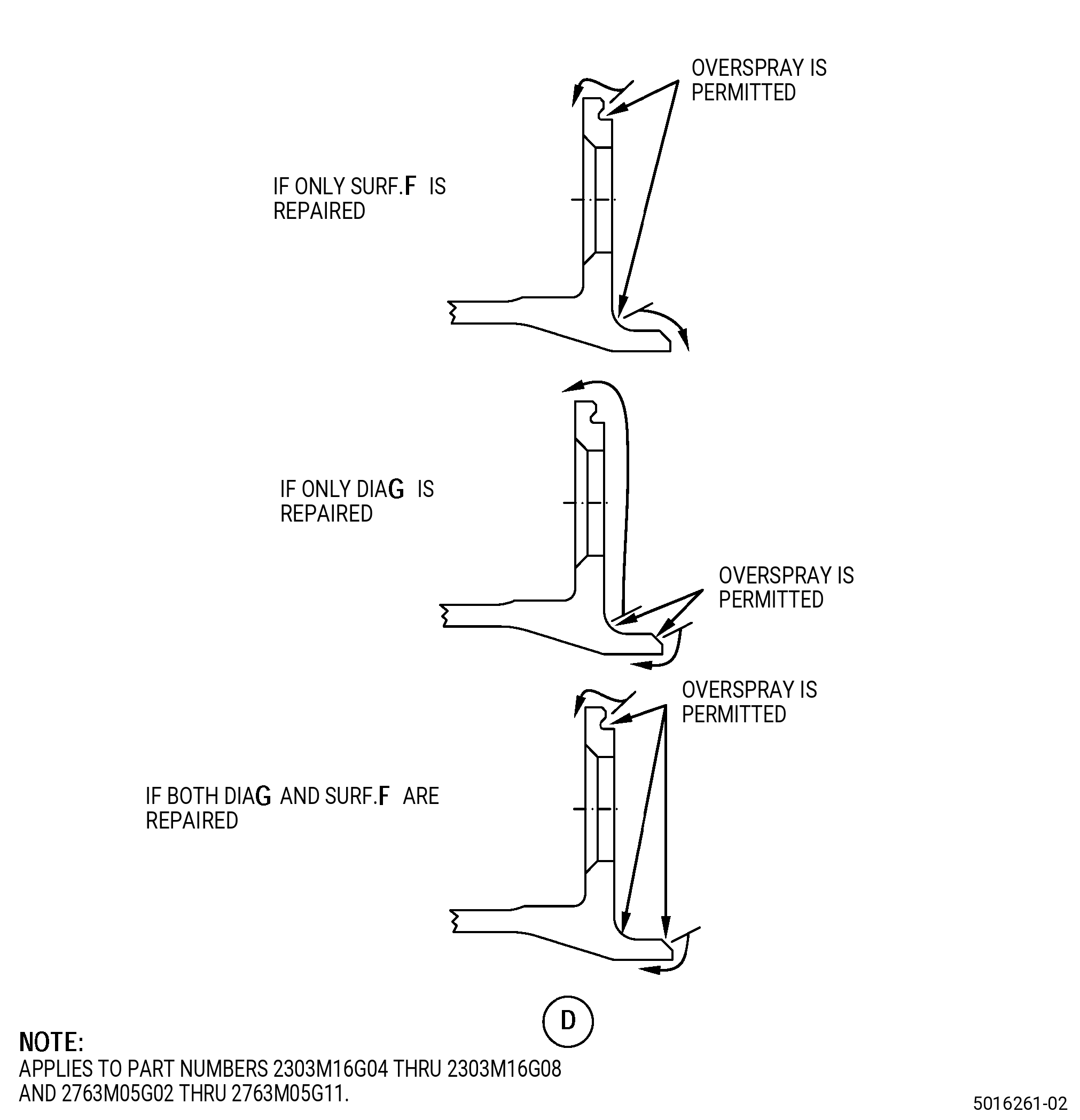
| STAGE 10 OUTLET GUIDE VANE - REPAIR - DIMENSIONAL RESTORATION OF SURFACE F AND DIAMETER G | ||
| GENX-1B CLEANING,INSPECTION,AND REPAIR MANUAL | Dated: 06/05/2024 | |
| CIR 72-41-20 , REPAIR 005 | ||
| STAGE 10 OUTLET GUIDE VANE - REPAIR - DIMENSIONAL RESTORATION OF SURFACE F AND DIAMETER G | ||
| * * * FOR ALL |
| TASK 72-41-20-300-807 |
| 1 . | Dimensional Restoration of Surface F and Diameter G. |
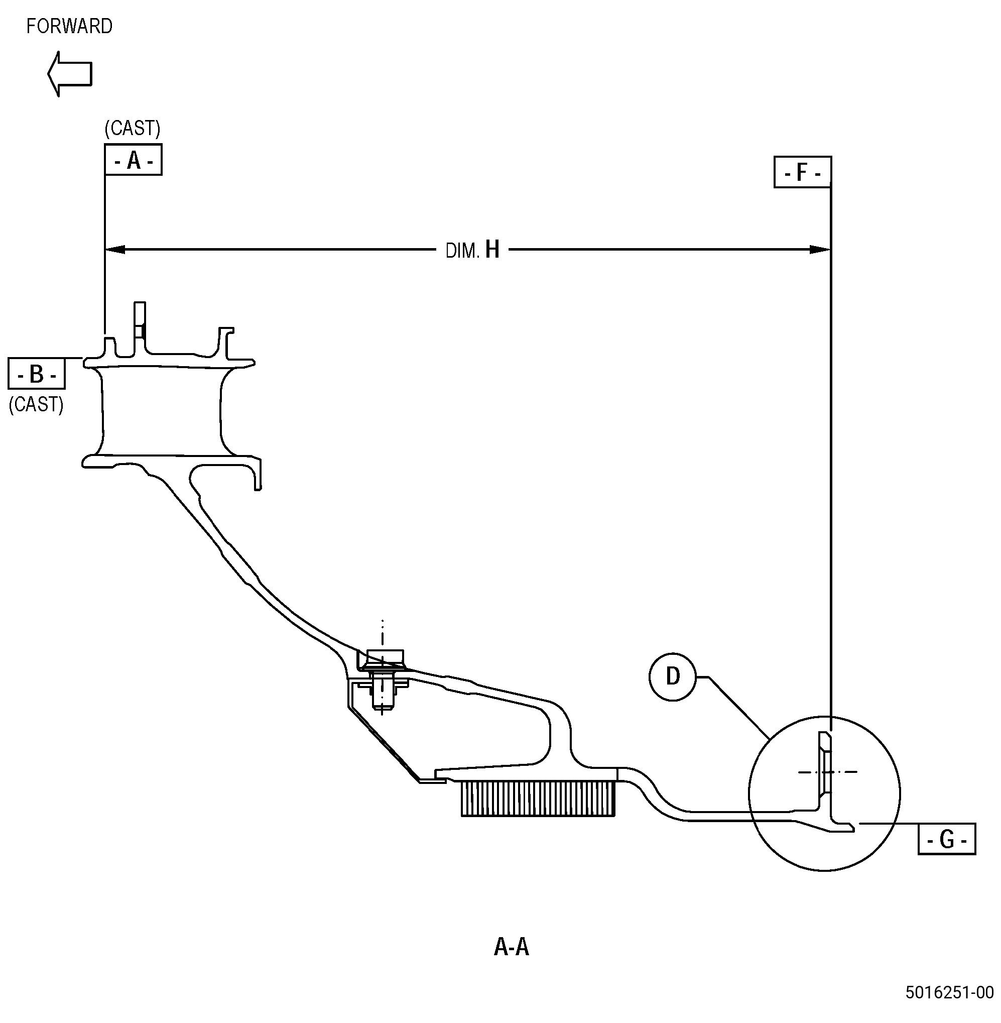
| A. | This procedure gives instructions to repair the stage 10 outlet guide vane (OGV) by thermal spraying with Rene 80 surface F and diameter G. Refer to Figure 901. |
| B. | The following maximum repairable limits apply to this repair: |
| NOTE: |
|
| (5) | Dimensional Inspection. |
| (c) | Do an inspection of the stage 10 OGV for: |
| 3 | Diameter G: |
| Maximum repairable limit: |
|
| 4 | Diameter G roundness (free state): |
| Maximum repairable limit: |
|
| 5 | Surface F flatness (free state): |
| Maximum repairable limit: |
|
| 6 | Dimension H: |
| Maximum repairable limit: |
|
| C. | The subsequent table gives a list of the part numbers that are applicable to this repair. All part numbers are applicable to all paragraphs unless specified differently. |
|
||||||||||||||||||||||||||||||||||||||||||||||||||||||||||||||
| D. | Proprietary/Complex Process Statement. |
| (1) | None. |
| 2 . | Tools, Equipment, and Materials. |
| NOTE: |
|
| A. | Tools and Equipment. |
| (1) | Special Tools. None. |
| (2) | Standard Tools and Equipment. None. |
| (3) | Locally Manufactured Tools. |
|
| B. | Consumable Materials. |
|
| C. | Referenced Procedures. |
| D. | Expendable Parts. None. |
| E. | SPD Information. |
| (1) | Locally Manufactured SPD. None. |
| F. | Special Solutions. None. |
| G. | Test Specimens. Refer to TASK 70-49-56-340-803 (THERMAL SPRAYING - STANDARD PRACTICE - THERMAL SPRAYING RENE 80 COATING) . |
| 3 . | Dimensional Information. |
| Subtask 72-41-20-220-071 |
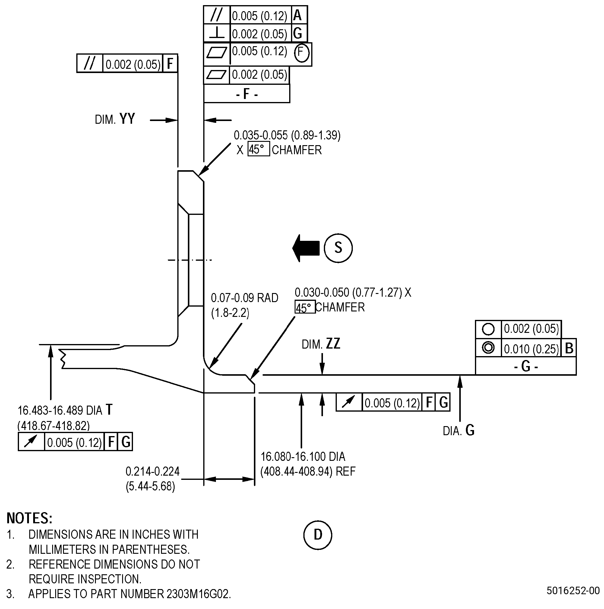
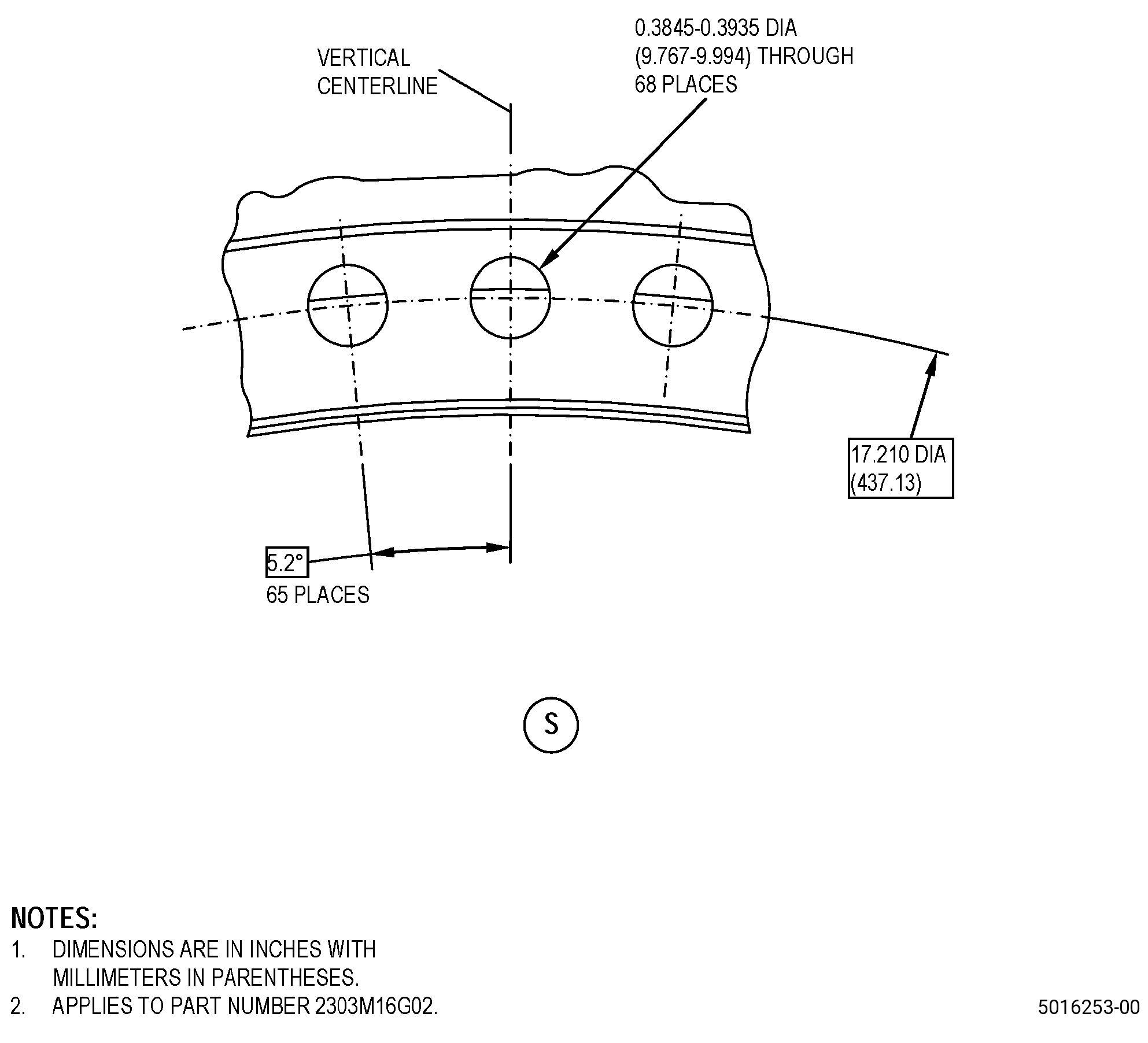
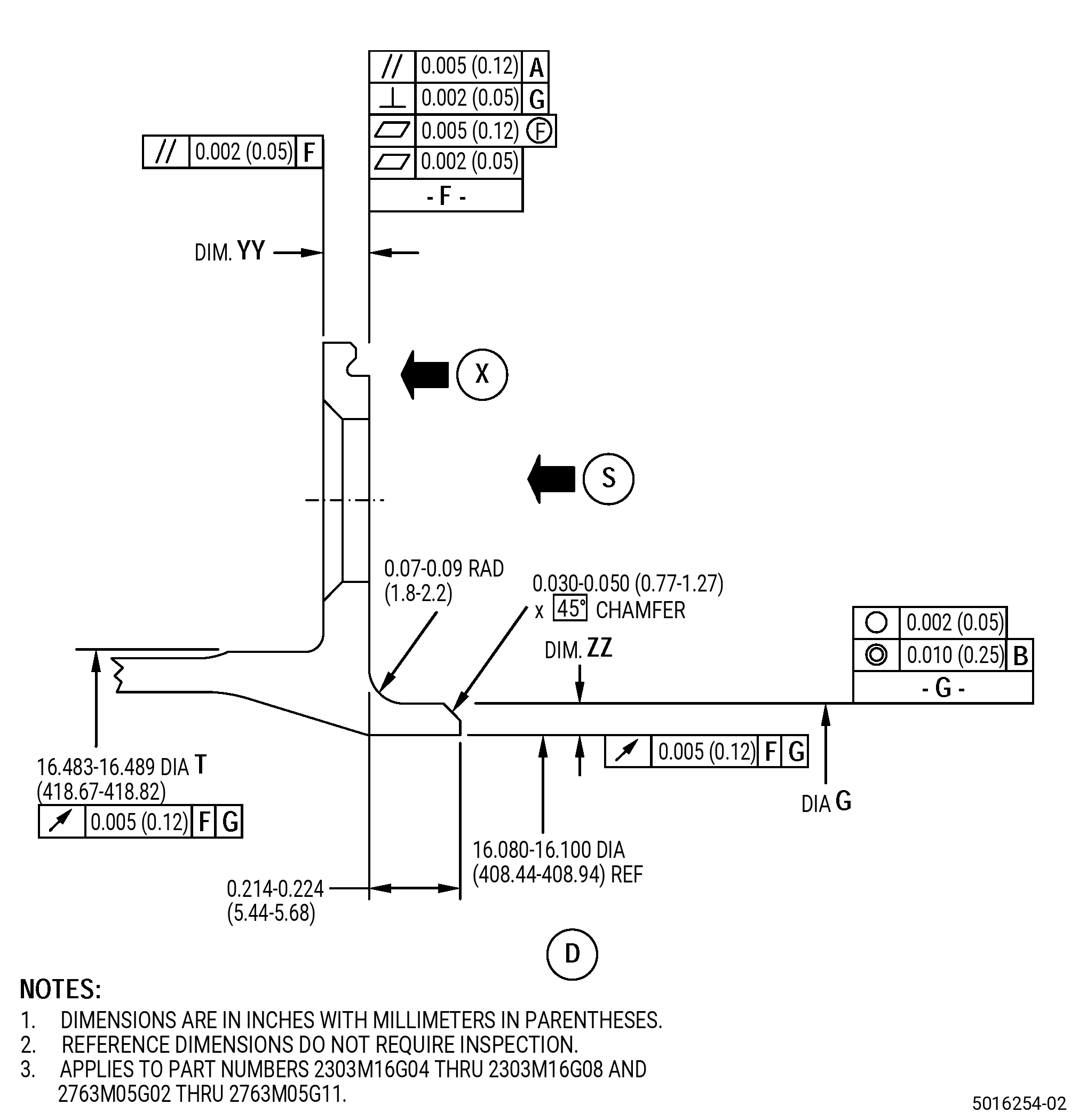
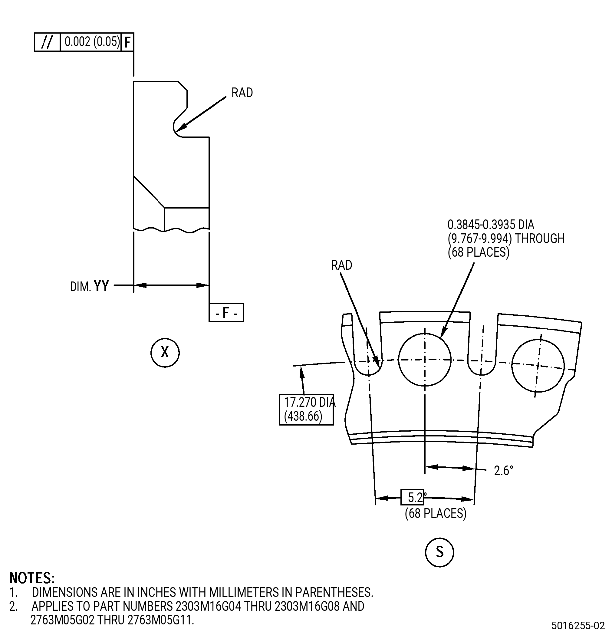
| A. | Refer to Figure 901 for specified dimensions and locations. |
| NOTE: |
|
| NOTE: |
|
| NOTE: |
|
| NOTE: |
|
|
| 4 . | Setup Information. |
| Subtask 72-41-20-350-032 |
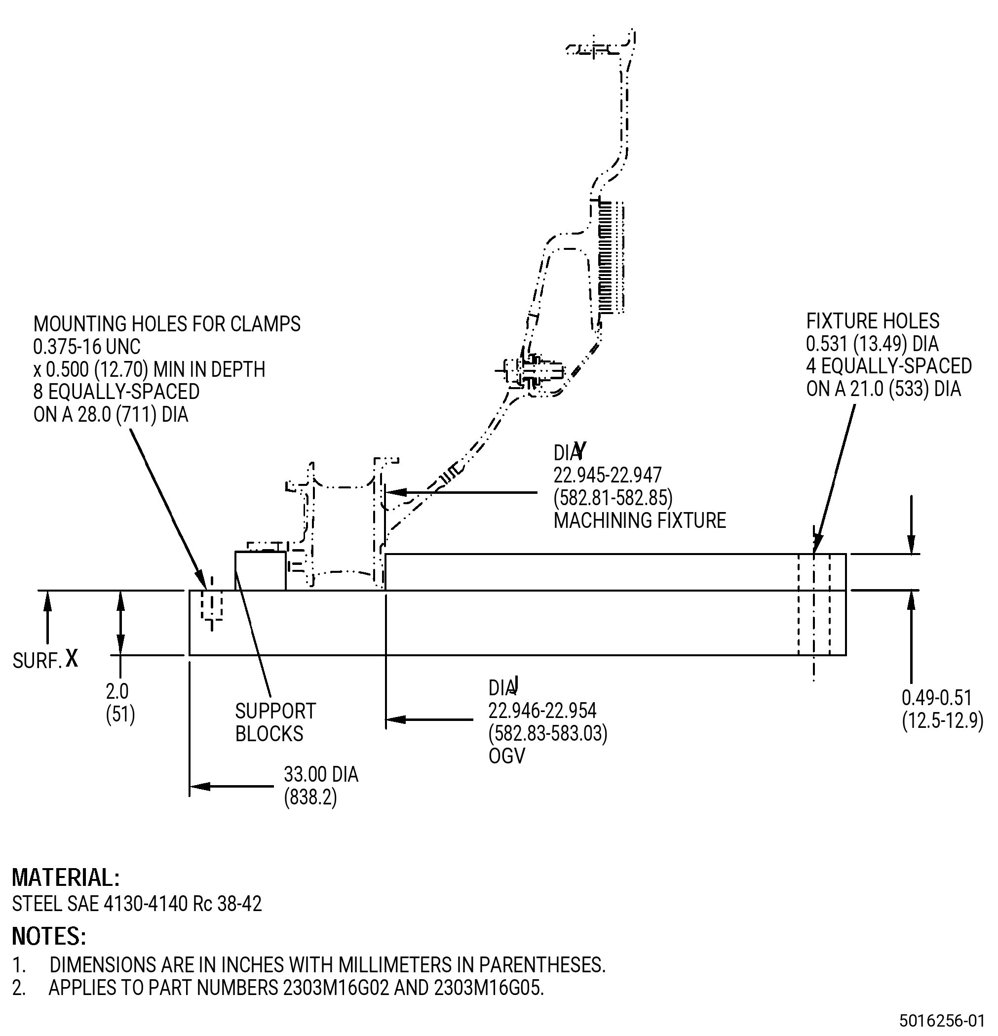
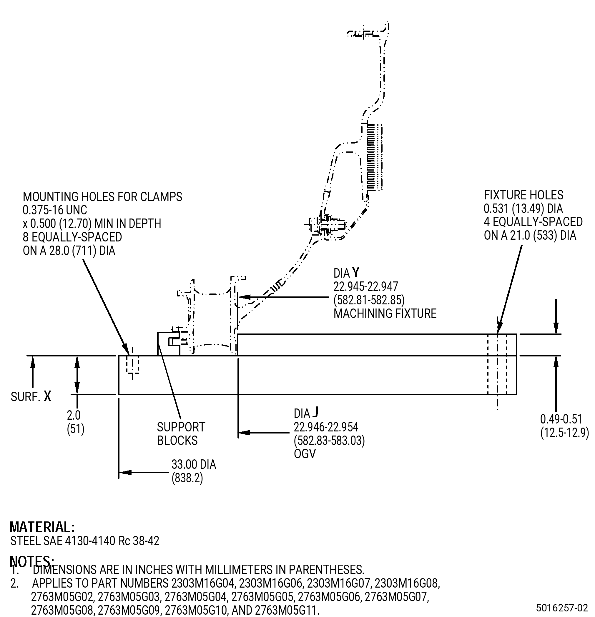
| A. | Set-up the OGV for machining. Refer to Figure 902 and as follows: |
| Subtask 72-41-20-930-001 |
| (1) | If necessary, make the machining fixture. |
| Subtask 72-41-20-350-031 |
| (2) | Install the machining fixture on the machining table as follows: |
| Subtask 72-41-20-350-045 |
| (a) | Adjust the position of the machining fixture to get the runout of surface X to 0.001 inch (0.02 mm) full indicator reading (FIR) or less as follows: |
| 1 | If necessary, put C10-155 shims between the machining fixture and the machining table to get the necessary runout. |
| Subtask 72-41-20-350-046 |
| (b) | If necessary, adjust the position of the machining fixture to make sure that the runout of diameter Y is 0.001 inch (0.02 mm) FIR or less. |
| (c) | Use four 0.500-13 UNC socket headed cap screws to hold the machining fixture to the machining table and as follows: |
| 1 | Make sure that the runouts of surface X and diameter Y agree with the requirements specified in Subtask 72-41-20-350-045 (paragraph 4.A.(2)(a)) and Subtask 72-41-20-350-046 (paragraph 4.A.(2)(b)) . |
| Subtask 72-41-20-350-044 |
| (3) | Install the OGV onto the machining fixture as follows: |
| (a) | Put the OGV onto the machining fixture with the forward side down. |
| (b) | Use clamps to attach the OGV to the OGV machining fixture. |
| Subtask 72-41-20-350-047 |
| (c) | Adjust the runout of the OGV diameter G in 0.004 inch (0.10 mm) or less as follows: |
| 1 | If necessary, add C10-155 shims to diameter J. |
| Subtask 72-41-20-220-078 |
| (4) | Make sure that you install the OGV flat on the machining fixture as follows: |
| (a) | The maximum permitted clearance between surface X of the machining fixture and the OGV is 0.002 inch (0.05 mm). |
| 5 . | Procedure. |
| Subtask 72-41-20-350-033 |
| CAUTION: |
|
| A. | You can do this repair a maximum of two times with the heat treatment procedures specified in Subtask 72-41-20-370-002 (paragraph 5.L.). If it is necessary to do this repair more than two times, you must remove the honeycomb. Refer to TASK 72-41-20-300-804 (72-41-20, REPAIR 007). |
| Subtask 72-41-20-160-007 |
| B. | If necessary, clean the OGV. Refer to TASK 72-41-20-100-801 (72-41-20, CLEANING 001). |
| Subtask 72-41-20-350-034 |
| C. | For P/N 2303M16G02 and P/N 2303M16G05 , remove the seal pins, springs, and leaf seals from the OGV. Refer to TASK 72-41-20-300-801 (72-41-20, REPAIR 001). |
| Subtask 72-41-20-350-035 |
| D. | Remove the three cover plates from the OGV. Refer to TASK 72-41-20-300-802 (72-41-20, REPAIR 003). |
| Subtask 72-41-20-230-006 |
| E. | Do an inspection of the OGV surface F/diameter G to find areas with thermal spray coating or indications/wear on parent material. Refer to TASK 70-32-00-200-002 (INDIRECT INSPECTION METHODS), TASK 70-32-03-230-002 (SPOT-FLUORESCENT-PENETRANT INSPECTION), and as follows: |
| (1) | Use Class A penetrant. |
| (2) | Look for signs of thermal spray coating and as follows: |
| NOTE: |
|
| (a) | If there is remaining thermal spray coating, go to Subtask 72-41-20-320-008 (paragraph 5.F.). |
| (3) | Refer to TASK 72-41-20-200-801 (72-41-20, INSPECTION 001) for acceptability limits. |
| Subtask 72-41-20-320-008 |
| CAUTION: |
|
| F. | Alternative Procedure Available. If necessary, machine the OGV surface F/diameter G to remove thermal spray coating or indications/wear on the parent material. Refer to TASK 70-00-03-800-004 (MACHINING DATA), Subtask 72-41-20-220-071 (paragraph 3.A.), Figure 901, and as follows: |
| NOTE: |
|
| NOTE: |
|
| Subtask 72-41-20-350-041 |
| (1) | Set-up the OGV for machining. Refer to Subtask 72-41-20-350-032 (paragraph 4.A.). |
| Subtask 72-41-20-320-011 |
| (2) | Machine the OGV to remove thermal spray coating or indications/wear on the parent material as follows: |
| (a) | Surface F/diameter G must agree with the in-process limits. |
| Subtask 72-41-20-320-009 |
| (b) | If necessary, work the OGV diameter G until it agrees with the runout specified in Subtask 72-41-20-350-047 (paragraph 4.A.(3)(c)) . Refer to TASK 70-47-05-350-023 (COLD-WORKING REPAIR). |
| NOTE: |
|
| (c) | Do not machine the fillet that connects surface F and diameter G. |
| (d) | If you cannot remove the thermal spray coating, indications, or wear by machining to the in-process limits, then you cannot repair the OGV with this procedure. |
| (3) | Remove the OGV from the machining fixture. |
| (4) | If necessary do Subtask 72-41-20-230-006 (paragraph 5.E.) and Subtask 72-41-20-320-008 (paragraph 5.F.) again. |
| Subtask 72-41-20-330-002 |
| F.A. | Alternative Procedure. If necessary, remove the thermal spray coating from surface F/diameter G of the OGV. Refer to TASK 70-23-00-100-001 (STRIPPING PROCEDURES), TASK 70-23-23-330-008 (REMOVAL OF COATINGS BY HIGH PRESSURE WATER STRIPPING), Subtask 72-41-20-220-071 (paragraph 3.A.), and Figure 901. |
| Subtask 72-41-20-220-072 |
| G. | Do a dimensional inspection of the OGV repair area. Refer to Subtask 72-41-20-220-071 (paragraph 3.A.), Figure 901, and as follows: |
| (1) | Make sure that dimension H/diameter G/dimension ZZ/dimension YY agree with the minimum in-process limits. |
| Subtask 72-41-20-350-036 |
| H. | Blend the OGV surface F/diameter G. Refer to TASK 70-42-00-350-002 (BLENDING AND REMOVAL OF HIGH METAL PROCEDURES) and as follows: |
| (1) | Break all sharp edges to 0.005-0.010 inch (0.13-0.25 mm). |
| Subtask 72-41-20-110-013 |
| I. | Etch the OGV machined areas. Refer to TASK 70-24-00-110-033 (ETCHING PROCEDURES FOR FLUORESCENT-PENETRANT INSPECTION), TASK 70-24-01-110-034 (SWAB ETCHING PROCEDURE), and as follows: |
| (1) | Use Class C etchant. |
| Subtask 72-41-20-230-007 |
| J. | Do an inspection of the OGV repair areas. Refer to TASK 70-32-00-200-002 (INDIRECT INSPECTION METHODS), TASK 70-32-03-230-002 (SPOT-FLUORESCENT-PENETRANT INSPECTION), and as follows: |
| (1) | Use Class A penetrant. |
| NOTE: |
|
| (2) | Thermal spray coating is not permitted. |
| (3) | Refer to TASK 72-41-20-200-801 (72-41-20, INSPECTION 001) for acceptability limits. |
| (4) | If you find indications that do not agree with these limits, you cannot repair the OGV with this procedure. |
| Subtask 72-41-20-160-008 |
| K. | Clean the OGV. Refer to TASK 72-41-20-100-801 (72-41-20, CLEANING 001). |
| Subtask 72-41-20-370-002 |
| L. | If you did Subtask 72-41-20-320-009 (paragraph 5.F.(2)(b)), heat-treat the OGV, otherwise go to Subtask 72-41-20-340-006 (paragraph 5.P.). Refer to TASK 70-44-00-800-010 (HEAT TREATING), TASK 70-44-03-370-004 (FURNACE HEAT TREATMENT), and as follows: |
| Subtask 72-41-20-370-003 |
| (1) | For P/N 2303M16G02 , P/N 2303M16G04 , P/N 2303M16G06 , P/N 2763M05G02 , P/N 2763M05G03 , P/N 2763M05G05 , P/N 2763M05G06 , P/N 2763M05G09 , and P/N 2763M05G10 do as follows: |
| (a) | Increase the temperature of the OGV to 1475°F plus or minus 25°F (802°C plus or minus 14°C) for 7 hours 50 minutes to 8 hours 10 minutes. |
| (b) | Decrease the temperature of the OGV to 1325°F plus or minus 25°F (718°C plus or minus 14°C) and hold this temperature for 7 hours 50 minutes to 8 hours 10 minutes. |
| (c) | Decrease the temperature of the OGV to 1150°F plus or minus 25°F (621°C plus or minus 14°C) at a minimum rate of 100°F (55.6°C) for each hour and hold this temperature for 7 hours 50 minutes to 8 hours 10 minutes. |
| (d) | Air-cool the OGV to room temperature. |
| Subtask 72-41-20-370-004 |
| (2) | For P/N 2303M16G05 , P/N 2303M16G07 , P/N 2303M16G08 , P/N 2763M05G04 , P/N 2763M05G07 , P/N 2763M05G08 , and P/N 2763M05G11 do as follows: |
| (a) | Increase the temperature of the OGV to 1450°F plus or minus 25°F (787°C plus or minus 14°C) for 1 hour 45 minutes to 2 hours 15 minutes. |
| (b) | Decrease the temperature of the OGV to 1300°F plus or minus 25°F (704°C plus or minus 14°C) and hold this temperature for 7 hours 45 minutes to 8 hours 15 minutes. |
| (c) | Decrease the temperature of the OGV to 1150°F plus or minus 25°F (621°C plus or minus 14°C) at a minimum rate of 100°F (55.6°C) for each hour and hold this temperature for 7 hours 45 minutes to 8 hours 15 minutes. |
| (d) | Air-cool the OGV to room temperature. |
| Subtask 72-41-20-110-014 |
| M. | Etch the OGV machined areas. Refer to TASK 70-24-00-110-033 (ETCHING PROCEDURES FOR FLUORESCENT-PENETRANT INSPECTION), TASK 70-24-01-110-034 (SWAB ETCHING PROCEDURE), and as follows: |
| (1) | Use Class C etchant. |
| Subtask 72-41-20-230-008 |
| N. | Do an inspection of the OGV repair areas. Refer to TASK 70-32-00-200-002 (INDIRECT INSPECTION METHODS), TASK 70-32-02-230-001 (FLUORESCENT PENETRANT INSPECTION), and as follows: |
| (1) | Use Class A penetrant. |
| NOTE: |
|
| (2) | Thermal spray coating is not permitted. |
| (3) | Refer to TASK 72-41-20-200-801 (72-41-20, INSPECTION 001) for acceptability limits. |
| Subtask 72-41-20-160-009 |
| O. | Clean the OGV. Refer to TASK 72-41-20-100-801 (72-41-20, CLEANING 001). |
| Subtask 72-41-20-340-006 |
| WARNING: |
|
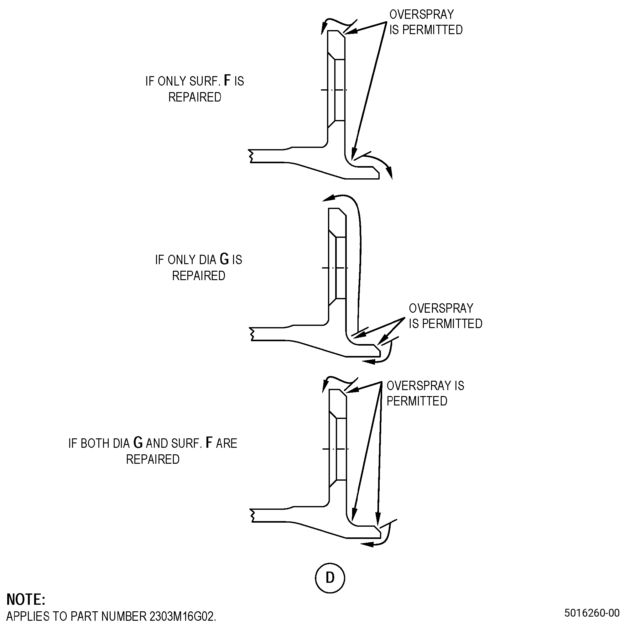
| P. | Thermal-spray the OGV surface F/diameter G and the test specimens. Refer to TASK 70-49-00-340-001 (THERMAL SPRAYING), TASK 70-49-56-340-803 (THERMAL SPRAYING - STANDARD PRACTICE - THERMAL SPRAYING RENE 80 COATING) , and as follows: |
| (1) | Apply C10-012 masking tape to the OGV adjacent areas to surface F/diameter G where thermal spray is not permitted. Refer to Figure 903. |
| (2) | Thermal spray coating is not permitted in the boltholes and as follows: |
| (a) | Use C10-198 plugs or similar for masking the boltholes and the slots of the scalloped flange. |
| (3) | Apply thermal spray coating to a maximum thickness of 0.040 inch (1.01 mm). |
| (4) | Do all the quality assurance testing specified in TASK 70-49-56-340-803 (THERMAL SPRAYING - STANDARD PRACTICE - THERMAL SPRAYING RENE 80 COATING). |
| CAUTION: |
|
| (5) | Remove the masking tape from the OGV. Carefully pull the masking tape away from the thermal spray coating. |
| Subtask 72-41-20-320-010 |
| Q. | Machine the OGV surface F/diameter G to agree with the finish limits. Refer to TASK 70-00-03-800-004 (MACHINING DATA), Subtask 72-41-20-220-071 (paragraph 3.A.), Figure 901, and as follows: |
| (1) | Make sure that there is a minimum thermal spray coating thickness of 0.004 inch (0.11 mm) in surface F and diameter G after final machining. |
| Subtask 72-41-20-350-043 |
| (2) | Set-up the OGV for machining. Refer to Subtask 72-41-20-350-032 (paragraph 4.A.). |
| Subtask 72-41-20-320-012 |
| (3) | Machine the OGV surface F/diameter G to agree with the finish limits. |
| (4) | For tolerances, refer to TASK 70-31-00-220-001 (DIMENSIONAL INSPECTION) and TASK 70-31-06-220-001 (MACHINED FEATURES SHOP-RUN TOLERANCES). |
| (5) | Remove the OGV from the machining fixture. |
| Subtask 72-41-20-350-037 |
| R. | Blend the OGV. Refer to TASK 70-42-00-350-002 (BLENDING AND REMOVAL OF HIGH METAL PROCEDURES). |
| Subtask 72-41-20-160-010 |
| S. | Clean the OGV. Refer to TASK 72-41-20-100-801 (72-41-20, CLEANING 001). |
| Subtask 72-41-20-220-073 |
| T. | Do a visual inspection of the thermal spray coating that you applied to the OGV. Refer to TASK 70-49-00-340-001 (THERMAL SPRAYING), TASK 70-49-56-340-803 (THERMAL SPRAYING - STANDARD PRACTICE - THERMAL SPRAYING RENE 80 COATING), and as follows: |
| (1) | No steps or undercuts are permitted. |
| Subtask 72-41-20-220-074 |
| U. | Do a dimensional inspection of the OGV. Refer to TASK 72-41-20-200-801 (72-41-20, INSPECTION 001). |
| Subtask 72-41-20-350-038 |
| V. | For P/N 2303M16G02 and P/N 2303M16G05 , install the seal pins, springs, and leaf seals in the OGV. Refer to TASK 72-41-20-300-801 (72-41-20, REPAIR 001). |
| Subtask 72-41-20-350-039 |
| W. | Install the three cover plates onto the OGV. Refer to TASK 72-41-20-300-802 (72-41-20, REPAIR 003). |
| Subtask 72-41-20-350-040 |
| X. | Put a mark on the case to show that the OGV was repaired by this repair. Refer to TASK 70-16-00-350-001 (MARKING PRACTICES), TASK 70-16-08-350-001 (DOT PEEN MARKING FOR OPTICAL CHARACTER RECOGNITION), and as follows: |
| (1) | Put a mark adjacent to the part number. |
| (2) | Use method 2 and put REPAIR YYY-XX adjacent to the part number and as follows: |
| (a) | If there is no mark in the repair, write 01 adjacent to YYY. |
| (b) | If there is a 01 mark, replace it by 02. |
| NOTE: |
|