| GENX-1B CLEANING,INSPECTION,AND REPAIR MANUAL | Dated: 06/05/2024 | |
| CIR 72-41-20 , REPAIR 006 | ||
| STAGE 10 OUTLET GUIDE VANE - REPAIR - REPLACEMENT OF THE T800 THERMAL SPRAY COATING ON THE W-SEAL SURFACE N, W-SEAL SURFACE M, AND RABBET DIAMETER C | ||
| GENX-1B CLEANING,INSPECTION,AND REPAIR MANUAL | Dated: 06/05/2024 | |
| CIR 72-41-20 , REPAIR 006 | ||
| STAGE 10 OUTLET GUIDE VANE - REPAIR - REPLACEMENT OF THE T800 THERMAL SPRAY COATING ON THE W-SEAL SURFACE N, W-SEAL SURFACE M, AND RABBET DIAMETER C | ||
| * * * FOR ALL |
| TASK 72-41-20-300-805 |
| 1 . | Replacement of the T800 Thermal Spray Coating on the W-Seal Surface N, W-Seal Surface M, and Rabbet Diameter C. |
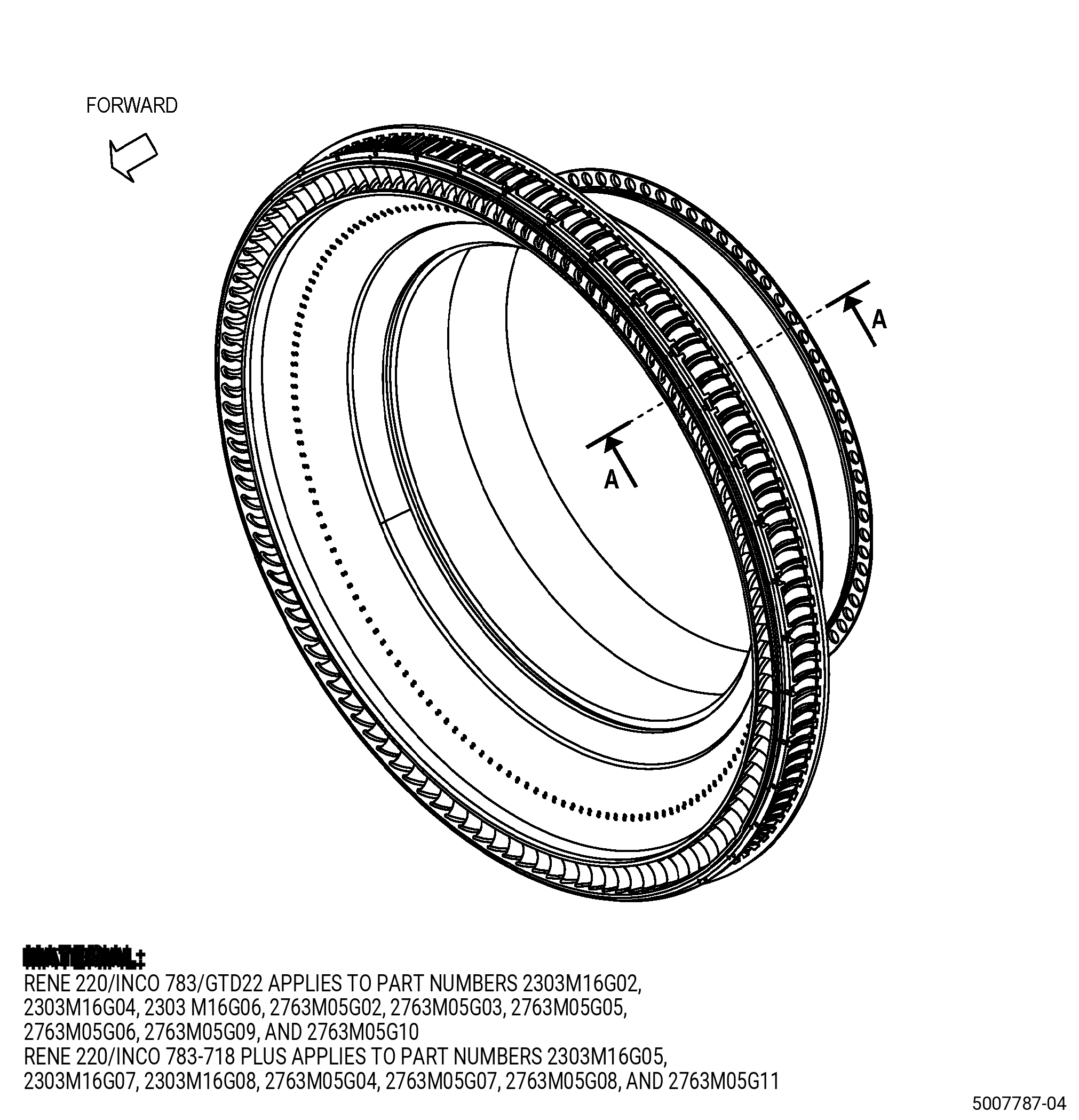
| A. | This procedure gives instructions to repair the stage 10 outlet guide vane (OGV) by removing and replacing the T800 thermal spray wear coating on the W-seal surface N, W-seal surface M, and rabbet diameter C. Refer to Figure 901. |
| B. | The following maximum repairable limits apply to this repair: |
| NOTE: |
|
| (4) | Visual Inspection. |
| (d) | Do an inspection of the wear coat on diameter C for the following. Refer to Figure 802. |
| 1 | Wear-through of the wear coat: |
| Maximum repairable limit: |
|
| 2 | Missing wear coat: |
| Maximum repairable limit: |
|
| 3 | Craze cracking: |
| Maximum repairable limit: |
|
| (e) | Do an inspection of the wear coat on surface N for the following. Refer to Figure 802. |
| 1 | Wear-through of the wear coat: |
| Maximum repairable limit: |
|
| 2 | Missing wear coat: |
| Maximum repairable limit: |
|
| 3 | Craze cracking: |
| Maximum repairable limit: |
|
| (l) | Do an inspection of the wear coat on surface M for the following. Refer to Figure 802. |
| 1 | Wear-through of the wear coat: |
| Maximum repairable limit: |
|
| 2 | Missing wear coat: |
| Maximum repairable limit: |
|
| 3 | Craze cracking: |
| Maximum repairable limit: |
|
| (5) | Dimensional Inspection. |
| (c) | Do an inspection of the stage 10 OGV for: |
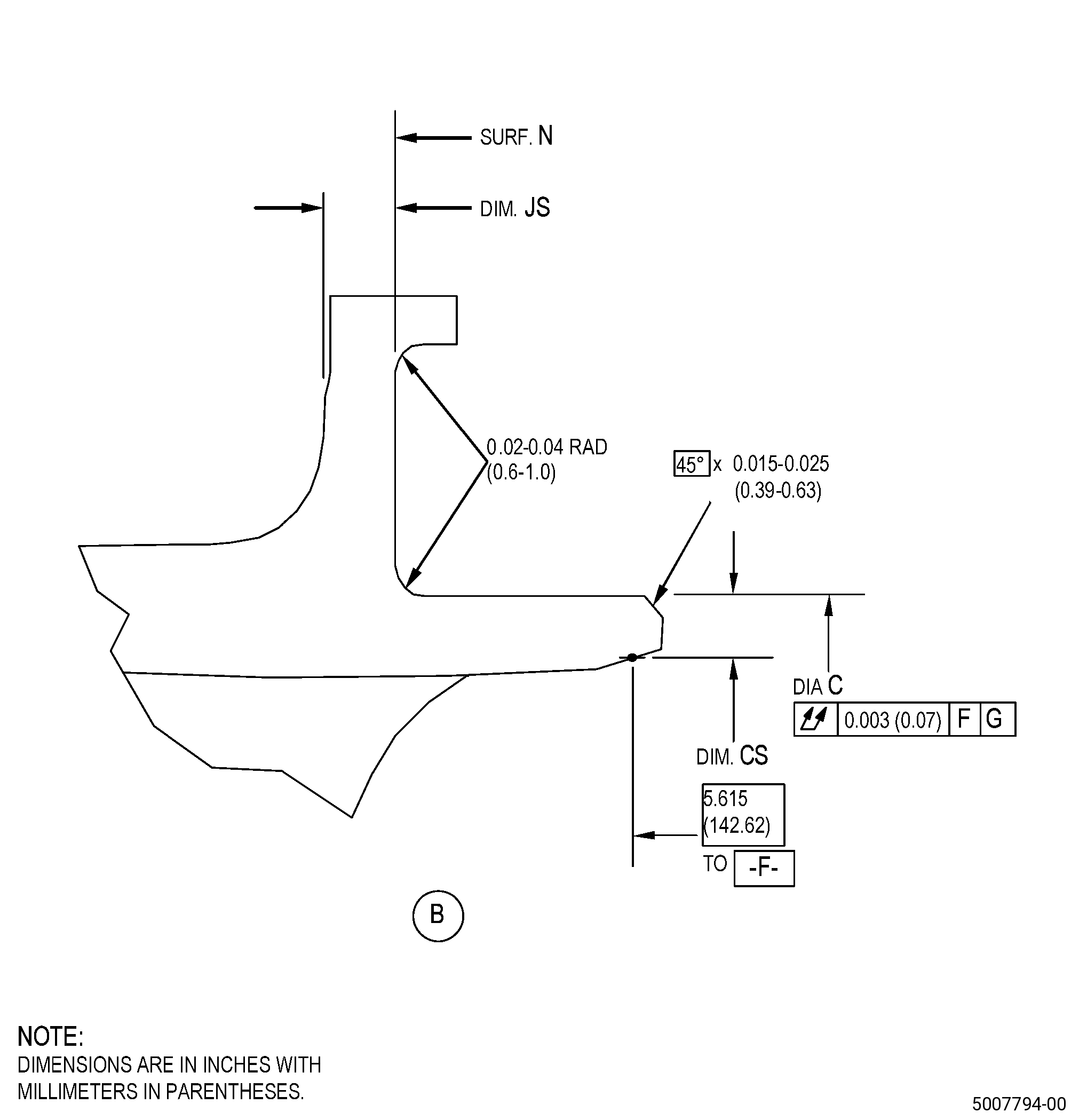
| 1 | Diameter C: |
| Maximum repairable limit: |
|
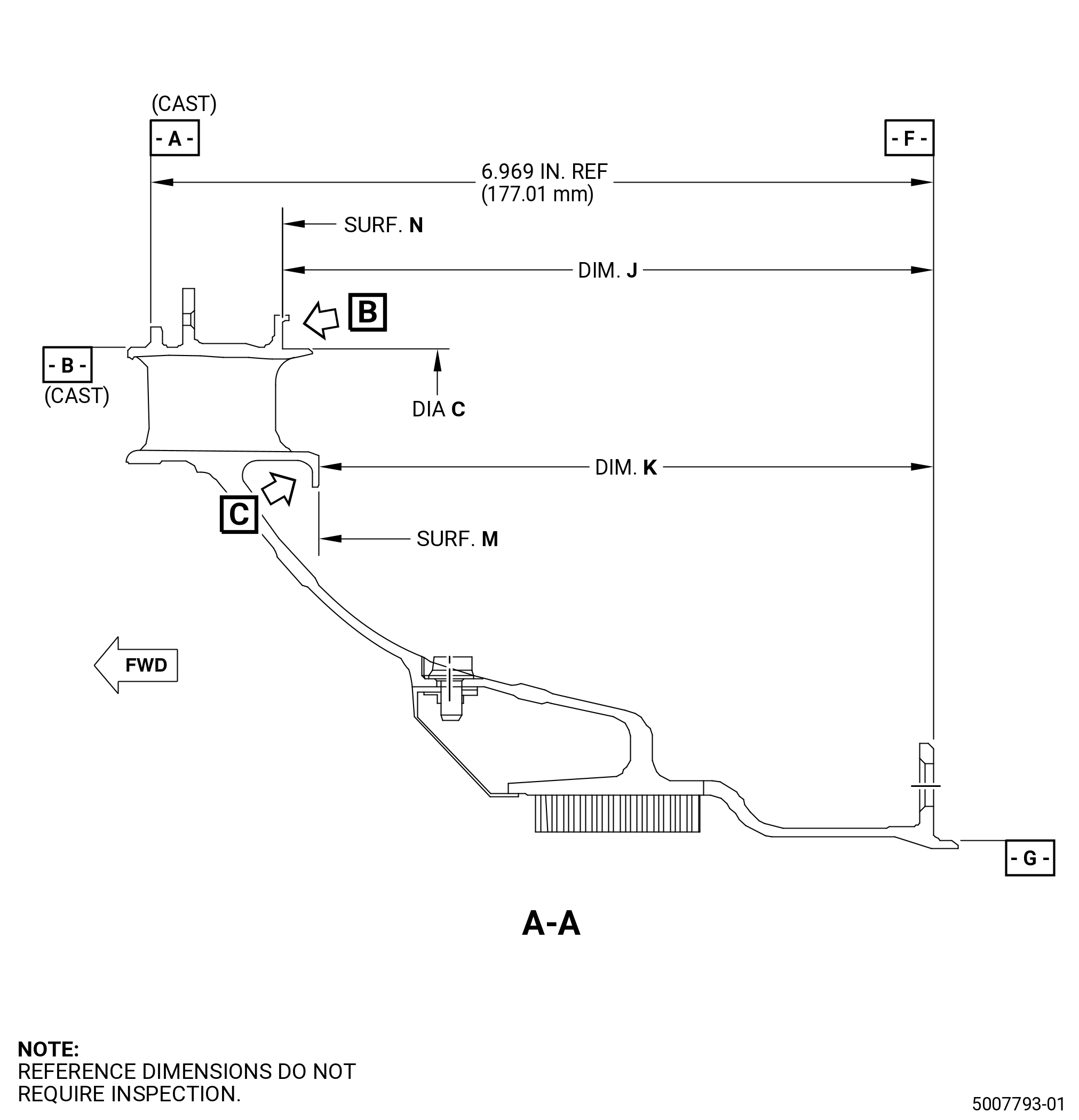
| 7 | Dimension J: |
| Maximum repairable limit: |
|
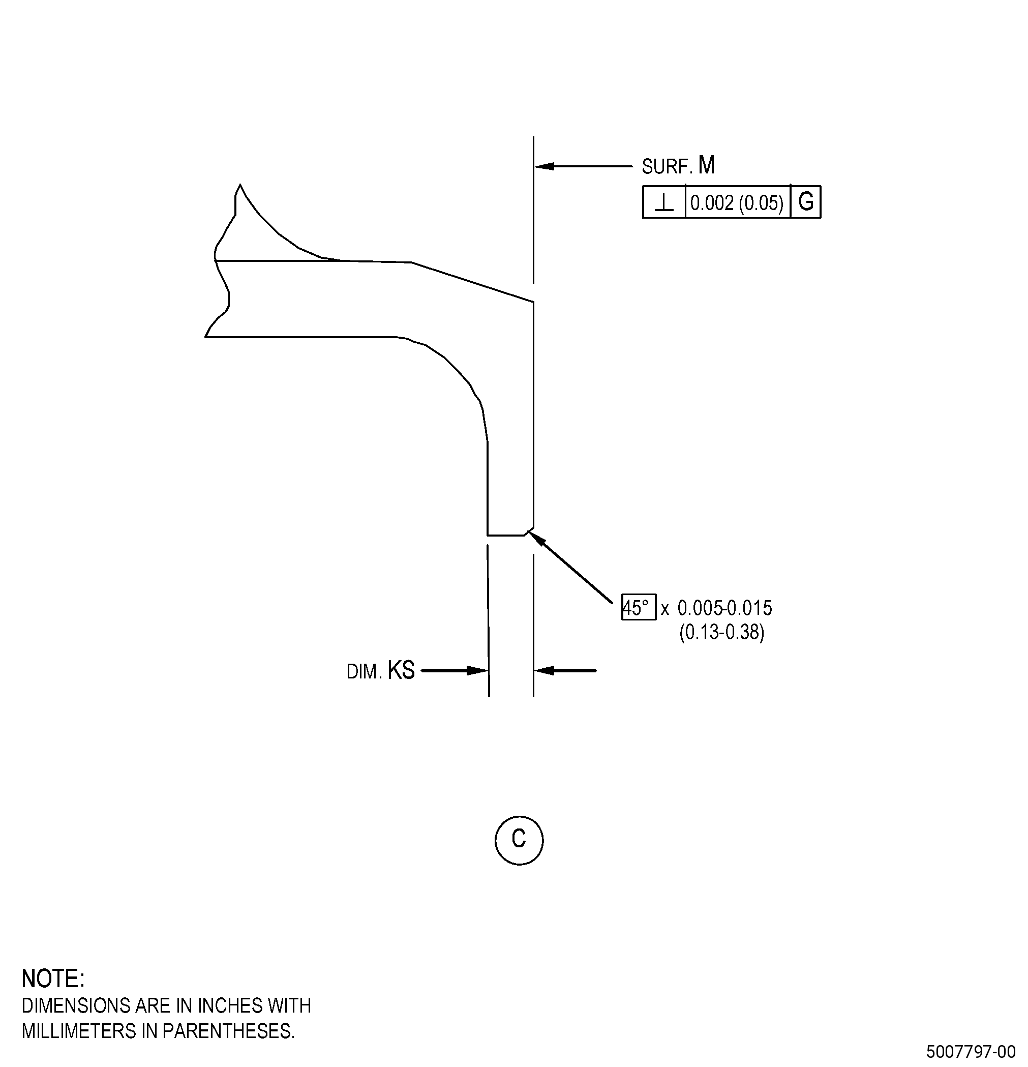
| 8 | Dimension K: |
| Maximum repairable limit: |
|
| C. | The subsequent table gives a list of the part numbers that are applicable to this repair. All part numbers are applicable to all paragraphs unless specified differently. |
|
||||||||||||||||||||||||||||||||||||||||||||||||||||||||||||||
| D. | Proprietary/Complex Process Statement. |
| (1) | None. |
| 2 . | Tools, Equipment, and Materials. |
| NOTE: |
|
| A. | Tools and Equipment. |
| (1) | Special Tools. None. |
| (2) | Standard Tools and Equipment. None. |
| (3) | Locally Manufactured Tools. |
|
| B. | Consumable Materials. |
|
| C. | Referenced Procedures. |
| D. | Expendable Parts. None. |
| E. | SPD Information. None. |
| (1) | Locally Manufactured SPD. None. |
| F. | Special Solutions. None. |
| G. | Test Specimens. Refer to TASK 70-49-43-340-042 (HIGH DENSITY HVOF T-800 (TRIBALOY) COATING), and TASK 70-49-50-340-049 (HIGH DENSITY HVOF RENE 80 COATING), or TASK 70-49-30-340-031 (THERMAL SPRAYING COBALT-MOLYBDENUM-CHROMIUM-SILICON ALLOY (POWDER) - TRIBALOY 800), and TASK 70-49-56-340-803 (THERMAL SPRAYING - STANDARD PRACTICE - THERMAL SPRAYING RENE 80 COATING). |
| 3 . | Dimensional Information. |
| Subtask 72-41-20-220-057 |
| A. | Refer to Figure 901 for specified dimensions and locations. |
| NOTE: |
|
| NOTE: |
|
| NOTE: |
|
| NOTE: |
|
|
| 4 . | Setup Information. |
| Subtask 72-41-20-350-017 |
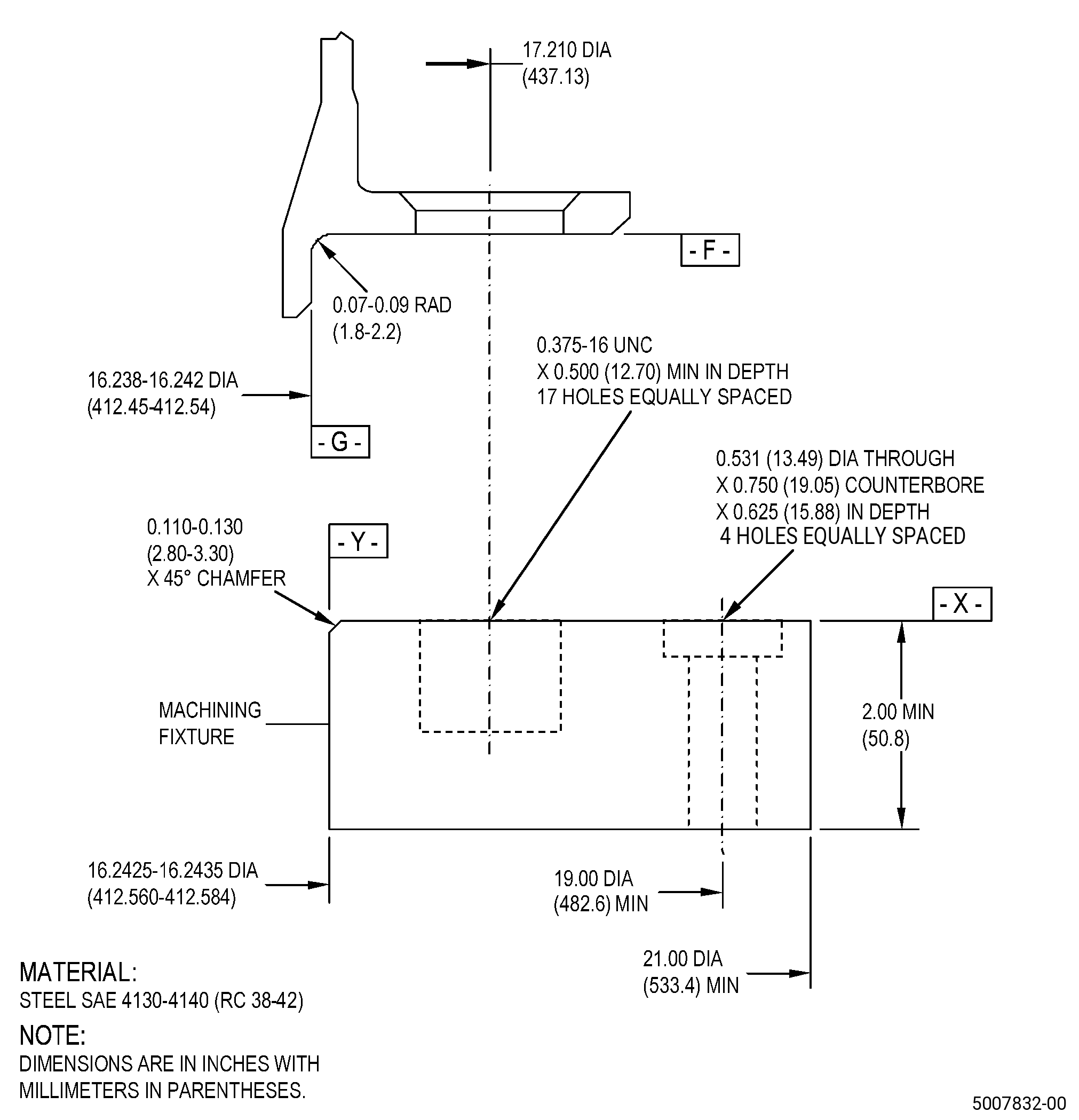
| A. | Set-up the OGV for machining. Refer to Figure 902 and as follows: |
| (1) | If necessary, make the machining fixture. |
| Subtask 72-41-20-350-028 |
| (2) | Install the machining fixture on the machining table as follows: |
| (a) | Adjust the position of the machining fixture to get the runout of surface X to 0.001 inch (0.02 mm) FIR or less as follows: |
| 1 | If necessary, put C10-155 shims between the machining fixture and the machining table to get the necessary runout. |
| Subtask 72-41-20-350-029 |
| (b) | If necessary, adjust the position of the machining fixture to make sure that the runout of diameter Y is 0.001 inch (0.02 mm) FIR or less. |
| (c) | Use four 0.500-13 UNC socket headed cap screws to hold the machining fixture to the machining table and as follows: |
| 1 | Make sure that the runouts of surface X and diameter Y agree with the requirements specified in Subtask 72-41-20-350-028 (paragraph 4.A.(2)(a)) and Subtask 72-41-20-350-029 (paragraph 4.A.(2)(b)). |
| Subtask 72-41-20-350-021 |
| (3) | Install the OGV onto the machining fixture as follows: |
| NOTE: |
|
| (a) | Put the OGV onto the machining fixture and align the boltholes in the flange with the 17 threaded holes in the machining fixture. |
| (b) | Attach the OGV to the machining fixture with 17 0.375-16 UNC bolts or screws. |
| Subtask 72-41-20-220-062 |
| (4) | Make sure that the OGV is installed flat on the machining fixture as follows: |
| (a) | The maximum permitted clearance between surface X of the machining fixture and surface F of the OGV is 0.002 inch (0.05 mm). |
| 5 . | Procedure. |
| Subtask 72-41-20-160-003 |
| A. | If necessary, clean the OGV. Refer to TASK 72-41-20-100-801 (72-41-20, CLEANING 001). |
| Subtask 72-41-20-350-018 |
| B. | If necessary, remove the pins, springs, and leaf seals from the OGV. Refer to TASK 72-41-20-300-801 (72-41-20, REPAIR 001). |
| Subtask 72-41-20-320-003 |
| CAUTION: |
|
| C. | Machine the OGV to remove the thermal spray coating and/or remove wear damage on surface N, surface M, and diameter C. Refer to TASK 70-00-03-800-004 (MACHINING DATA), Subtask 72-41-20-220-057 (paragraph 3.A.), Dimensional Information, Figure 901, Figure 903, and as follows: |
| NOTE: |
|
| NOTE: |
|
| (1) | If there is no wear on the parent material and you removed the thermal spray coating, go to Subtask 72-41-20-110-012 (paragraph 5.E.). |
| Subtask 72-41-20-350-022 |
| (2) | Set-up the OGV for machining. Refer to Subtask 72-41-20-350-017 (paragraph 4.A.), Setup Information. |
| Subtask 72-41-20-320-004 |
| CAUTION: |
|
| (3) | Machine surface N in area BC, surface M in area BD, and diameter C in area BE to remove the HVOF thermal spray coating as follows: |
| NOTE: |
|
| NOTE: |
|
| NOTE: |
|
| NOTE: |
|
| NOTE: |
|
| (a) | Do not remove more material than necessary to remove the thermal spray coating on the parent material. |
| (b) | If you cannot remove the thermal spray coating to the minimum in-process dimensions of dimension JS, dimension KS, and dimension CS, then you cannot repair the OGV with this procedure. |
| Subtask 72-41-20-320-005 |
| (4) | If necessary, machine surface N in area BC, surface M in area BD, and diameter C in area BE to remove wear on the parent material as follows: |
| (a) | Do not remove more material than is necessary to remove wear damage or raised material on the parent material. |
| (b) | If you cannot remove wear damage to the minimum in-process dimensions of dimension JS, dimension KS, and/or dimension CS, then you cannot repair the OGV with this procedure. |
| Subtask 72-41-20-220-063 |
| (5) | Do a dimensional inspection of diameter C. Refer to TASK 70-31-00-220-001 (DIMENSIONAL INSPECTION), TASK 70-31-06-220-001 (MACHINED FEATURES SHOP-RUN TOLERANCES), Figure 901, and as follows: |
| (a) | Do an inspection of the runout of diameter C in area BE. |
| Subtask 72-41-20-320-006 |
| (6) | If necessary, machine the OGV to agree with the dimensional limits for the runout of diameter C in area BE, surface M in area BD, and as follows: |
| (a) | Do not remove more material than is necessary to meet the dimensional limits for runout of diameter C in area BE and surface M in area BD. |
| (b) | If you cannot meet the dimensional limits for runout of diameter C in area BE and surface M in area BD, and the minimum in-process dimension of dimension CS and dimension KS, then you cannot repair the OGV with this procedure. |
| Subtask 72-41-20-350-023 |
| (7) | Blend the OGV repair areas. Refer to TASK 70-42-00-350-002 (BLENDING AND REMOVAL OF HIGH METAL PROCEDURES), and as follows: |
| (a) | Break all sharp edges to 0.005-0.010 inch (0.13-0.25 mm). |
| Subtask 72-41-20-350-024 |
| (8) | Remove the OGV from the machining fixture. |
| Subtask 72-41-20-220-068 |
| D. | Do an inspection of the OGV repair areas. Refer to Subtask 72-41-20-220-057 (paragraph 3.A.), Dimensional Information, Figure 901, Figure 902, and as follows: |
| (1) | Do an inspection to make sure that dimension JS, dimension KS, and dimension CS agree with the minimum in-process dimensions. |
| (2) | Measure dimension J in area BC, dimension K in area BD, and diameter C in area BE and record the in-process dimensions to use them later. Refer to Subtask 72-41-20-340-001 (paragraph 5.I.). |
| (3) | Remove the OGV from the machining fixture. |
| Subtask 72-41-20-110-012 |
| E. | Etch the OGV blended areas. Refer to TASK 70-24-00-110-033 (ETCHING PROCEDURES FOR FLUORESCENT-PENETRANT INSPECTION), TASK 70-24-01-110-034 (SWAB ETCHING PROCEDURE), and as follows: |
| (1) | Use Class C etchant. |
| Subtask 72-41-20-230-005 |
| F. | Do an inspection of the OGV repair areas. Refer to TASK 70-32-00-200-002 (INDIRECT INSPECTION METHODS), TASK 70-32-03-230-002 (SPOT-FLUORESCENT-PENETRANT INSPECTION), and as follows: |
| (1) | Use Class A penetrant. |
| (2) | Through Indications are not permitted. |
| Subtask 72-41-20-220-064 |
| (3) | Indications less than 0.030 inch (0.76 mm) are permitted. |
| (4) | Indications 0.030-0.060 inch (0.77-1.52 mm) are permitted if they agree with the conditions that follow: |
| (a) | They are not linear indications. |
| NOTE: |
|
| (b) | The distance between indications is a minimum of 0.250 inch (6.35 mm). |
| (5) | Microshrinkage must agree with GEAE Photo Standard 8311253, Class 20. |
| (6) | If you find indications that do not agree with these limits, you cannot repair the OGV with this procedure. |
| Subtask 72-41-20-160-004 |
| G. | If necessary, clean the OGV. Refer to TASK 72-41-20-100-801 (72-41-20, CLEANING 001). |
| Subtask 72-41-20-220-065 |
| H. | Use dimension J, dimension K, and diameter C recorded in Subtask 72-41-20-220-068 (paragraph 5.D.) to calculate the coating thickness that is necessary to get the finish dimensions of dimension J, dimension K, and diameter C after final machining. Refer to Subtask 72-41-20-220-057 (paragraph 3.A.), Dimensional Information. |
| Subtask 72-41-20-340-001 |
| WARNING: |
|
| I. | Alternative Procedure Available. Thermal-spray the OGV repair surface in area BC, area BD, and diameter C in area BE and the test specimens. Refer to Figure 901, Figure 903, and as follows: |
| CAUTION: |
|
| (1) | Apply C10-012 masking tape to the OGV in area BH and adjacent areas where thermal spray is not permitted. |
| (2) | Prepare the test specimens of similar material for the thermal spray coating application as follows: |
| (a) | Put the test specimens in an area that will let them receive the same thickness of thermal spray coating as the OGV repair areas. Refer to paragraph 2.G. |
| (b) | Make sure that you apply the buildup coating and the top coating to the test specimens. |
| (3) | If necessary, apply thermal spray buildup coating to the OGV surface N in area BC, surface M in area BD, and diameter C in area BE. Refer to TASK 70-49-00-340-001 (THERMAL SPRAYING), TASK 70-49-50-340-049 (HIGH DENSITY HVOF RENE 80 COATING), and as follows: |
| (a) | Apply the thermal spray buildup coating to a thickness of 0.003-0.070 inch (0.08-1.77 mm). |
| Subtask 72-41-20-220-066 |
| (b) | Make sure that after you apply the buildup thermal spray coating there is sufficient thickness margin to apply the top coating to a thickness of 0.0035-0.0075 inch (0.089-0.190 mm) after the final machining and still agree with the finish dimensions. Refer to Subtask 72-41-20-220-057 (paragraph 3.A.), Dimensional Information, Figure 901, Figure 903, and as follows: |
| 1 | Diameter C must be in the range of 24.9550-24.9710 inches (633.857-634.263 mm) after you apply the buildup coating. |
| 2 | Dimension J must be in the range of 5.8215-5.8275 inches (147.867-148.018 mm) after you apply the buildup coating. |
| 3 | Dimension K must be in the range of 5.4735-5.4775 inches (139.027-139.128 mm) after you apply the buildup coating. |
| Subtask 72-41-20-340-002 |
| (c) | Overspray is not permitted during the application of the buildup coating. |
| (d) | Do the quality assurance testing specified in TASK 70-49-50-340-049 (HIGH DENSITY HVOF RENE 80 COATING). |
| Subtask 72-41-20-340-003 |
| (4) | Apply thermal spray top coating to the OGV surface N in area BC, surface M in area BD, and diameter C in area BE. Refer to TASK 70-49-00-340-001 (THERMAL SPRAYING), TASK 70-49-43-340-042 (HIGH DENSITY HVOF T-800 (TRIBALOY) COATING), Subtask 72-41-20-220-057 (paragraph 3.A.), Dimensional Information, and as follows: |
| NOTE: |
|
| (a) | The thickness of the thermal spray top coating must be in the range of 0.0035-0.0075 inch (0.089-0.190 mm) after final machining. |
| (b) | Overspray is not permitted on area BH. |
| (c) | Overspray is permitted on area BF, area BG, and area BJ if it agrees with the maximum permitted limit of 0.007 inch (0.17 mm). |
| Subtask 72-41-20-340-004 |
| (5) | Do all the quality assurance testing specified in TASK 70-49-50-340-049 (HIGH DENSITY HVOF RENE 80 COATING), and TASK 70-49-43-340-042 (HIGH DENSITY HVOF T-800 (TRIBALOY) COATING). |
| NOTE: |
|
| Subtask 72-41-20-350-025 |
| CAUTION: |
|
| (6) | Remove the masking tape as follows: |
| (a) | Carefully pull the masking tape away from the thermal spray coating. |
| (7) | If necessary, blend the OGV adjacent surfaces to remove the over-spray. Refer to TASK 70-42-00-350-002 (BLENDING AND REMOVAL OF HIGH METAL PROCEDURES), and Figure 903. |
| NOTE: |
|
| Subtask 72-41-20-340-007 |
| WARNING: |
|
| I.A. | Alternative Procedure. Thermal-spray the OGV repair surface in area BC, area BD, and diameter C in area BE, and as follows: |
| CAUTION: |
|
| (1) | Apply C10-012 masking tape to the OGV in area BH and adjacent areas where thermal spray is not permitted. |
| (2) | Prepare the test specimens of similar material for the thermal spray coating application as follows: |
| (a) | Put the test specimens in an area that will let them receive the same thickness of thermal spray coating as the OGV repair areas. Refer to paragraph 2.G. |
| (b) | Make sure that you apply the buildup coating and the top coating to the test specimens. |
| (3) | If necessary, apply thermal spray buildup coating to the OGV surface N in area BC, surface M in area BD, and diameter C in area BE. Refer to TASK 70-49-00-340-001 (THERMAL SPRAYING), TASK 70-49-56-340-803 (THERMAL SPRAYING - STANDARD PRACTICE - THERMAL SPRAYING RENE 80 COATING) , and as follows: |
| (a) | Apply the thermal spray buildup coating to a thickness of 0.003-0.070 inch (0.08-1.77 mm). |
| Subtask 72-41-20-220-109 |
| (b) | Make sure that after you apply the buildup thermal spray coating, there is a sufficient thickness margin to apply the top coating to a thickness of 0.0035-0.0075 inch (0.089-0.190 mm) after the final machining and still agrees with the finish dimensions. Refer to Subtask 72-41-20-220-057 (paragraph 3.A.), Figure 901, Figure 903, and as follows: |
| 1 | Diameter C must be in the range of 24.9550-24.9710 inches (633.857-634.263 mm) after you apply the buildup coating. |
| 2 | Dimension J must be in the range of 5.8215-5.8275 inches (147.867-148.018 mm) after you apply the buildup coating. |
| 3 | Dimension K must be in the range of 5.4735-5.4775 inches (139.027-139.128 mm) after you apply the buildup coating. |
| Subtask 72-41-20-340-008 |
| (c) | Overspray is not permitted during the application of the buildup coating. |
| (d) | Do the quality assurance testing specified in TASK 70-49-56-340-803 (THERMAL SPRAYING - STANDARD PRACTICE - THERMAL SPRAYING RENE 80 COATING) . |
| Subtask 72-41-20-340-009 |
| (4) | Apply thermal-spray top coating to the OVG surface N in area BC, surface M in area BD, and diameter C in area BE. Refer to TASK 70-49-00-340-001 (THERMAL SPRAYING), TASK 70-49-30-340-031 (THERMAL SPRAYING COBALT-MOLYBDENUM-CHROMIUM-SILICON ALLOY (POWDER) - TRIBALOY 800), Subtask 72-41-20-200-057 (paragraph 3.A.), and as follows: |
| NOTE: |
|
| (a) | The thermal spray coating thickness after the final machining must be 0.0035-0.0075 inch (0.089-0.190 mm). |
| NOTE: |
|
| Subtask 72-41-20-340-010 |
| (5) | Do all the quality assurance testing specified in TASK 70-49-30-340-031 (THERMAL SPRAYING COBALT-MOLYBDENUM-CHROMIUM-SILICON ALLOY (POWDER) - TRIBALOY 800). |
| Subtask 72-41-20-350-086 |
| CAUTION: |
|
| (6) | Remove the masking tape. |
| (7) | If necessary, blend the OGV adjacent surfaces to remove the over-spray. Refer to TASK 70-42-00-350-002 (BLENDING AND REMOVAL OF HIGH METAL PROCEDURES) and Figure 903. |
| NOTE: |
|
| Subtask 72-41-20-320-007 |
| J. | Machine the OGV surface N in area BC, surface M in area BD, and diameter C in area BE. Refer to TASK 70-00-03-800-004 (MACHINING DATA), Subtask 72-41-20-220-057 (paragraph 3.A.), Dimensional Information, Figure 901, and as follows: |
| (1) | Set-up the OGV for machining. Refer to Subtask 72-41-20-350-017 (paragraph 4.A.), Setup information. |
| (2) | Machine the OGV surface N in area BC, surface M in area BD, and diameter C in area BE to the finish dimensions and as follows: |
| (a) | The OGV must agree with the dimensional dimensions for runout of surface N in area BC. |
| Subtask 72-41-20-350-026 |
| (3) | If necessary, blend the OGV repair area. Refer to TASK 70-42-00-350-002 (BLENDING AND REMOVAL OF HIGH METAL PROCEDURES), and as follows: |
| (a) | Blend the overspray at area BL to make a smooth transition from surface BE to the adjacent surface on diameter C with a maximum forward facing step of 0.0075 inch (0.190 mm). |
| (b) | If necessary, blend the OGV to remove overspray that is not permitted. |
| (c) | Break all sharp edges to 0.005-0.010 inch (0.13-0.25 mm). |
| Subtask 72-41-20-220-067 |
| (4) | Do a dimensional inspection of the OGV. Refer to TASK 70-31-00-220-001 (DIMENSIONAL INSPECTION), TASK 70-31-06-220-001 (MACHINED FEATURES SHOP-RUN TOLERANCES), and Subtask 72-41-20-220-057 (paragraph 3.A.), Dimensional Information. |
| (5) | Remove the OGV from the machining fixture. |
| Subtask 72-41-20-160-005 |
| K. | Clean the OGV. Refer to TASK 72-41-20-100-801 (72-41-20, CLEANING 001). |
| Subtask 72-41-20-340-005 |
| L. | Do an inspection of the OGV as specified in TASK 70-49-00-340-001 (THERMAL SPRAYING) and TASK 70-49-43-340-042 (HIGH DENSITY HVOF T-800 (TRIBALOY) COATING), or in TASK 70-49-30-340-031 (THERMAL SPRAYING COBALT-MOLYBDENUM-CHROMIUM-SILICON ALLOY (POWDER) - TRIBALOY 800), and as follows: |
| (1) | Use white light and 10X magnification. |
| (2) | Blisters, chipping, cracks, flaking, spalling, or splatter of the coating compound are not permitted. |
| (3) | Surface finish must be 120 microinches (3.0 micrometers) or better. |
| (4) | A surface finish of 140 microinches (3.5 micrometers) is permitted on 10 percent of the circumference. |
| Subtask 72-41-20-350-027 |
| M. | If necessary, install the leaf seals, springs, and pins on the OGV. Refer to TASK 72-41-20-300-801 (72-41-20, REPAIR 001). |