| GENX-1B ENGINE MANUAL | Dated: 09/15/2023 | |
| EM 72-53-00 , ASSEMBLY 001 | ||
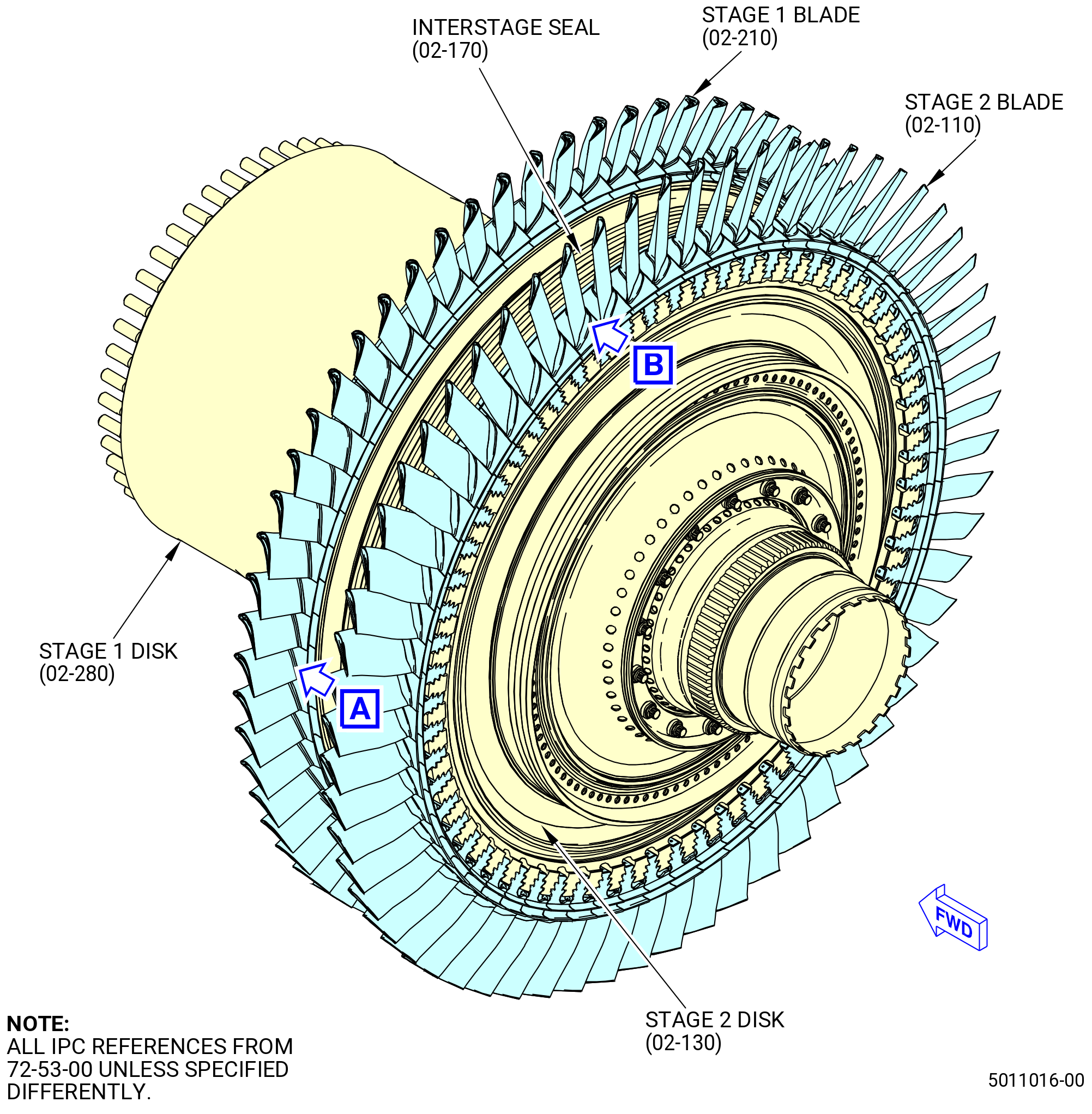
| HIGH PRESSURE TURBINE ROTOR ASSEMBLY - ASSEMBLY 001 - CONFIGURATION 02 | ||
| GENX-1B ENGINE MANUAL | Dated: 09/15/2023 | |
| EM 72-53-00 , ASSEMBLY 001 | ||
| HIGH PRESSURE TURBINE ROTOR ASSEMBLY - ASSEMBLY 001 - CONFIGURATION 02 | ||
| * * * FOR ALL PIP 2 |
| TASK 72-53-00-440-803 |
| 1 . | General. |
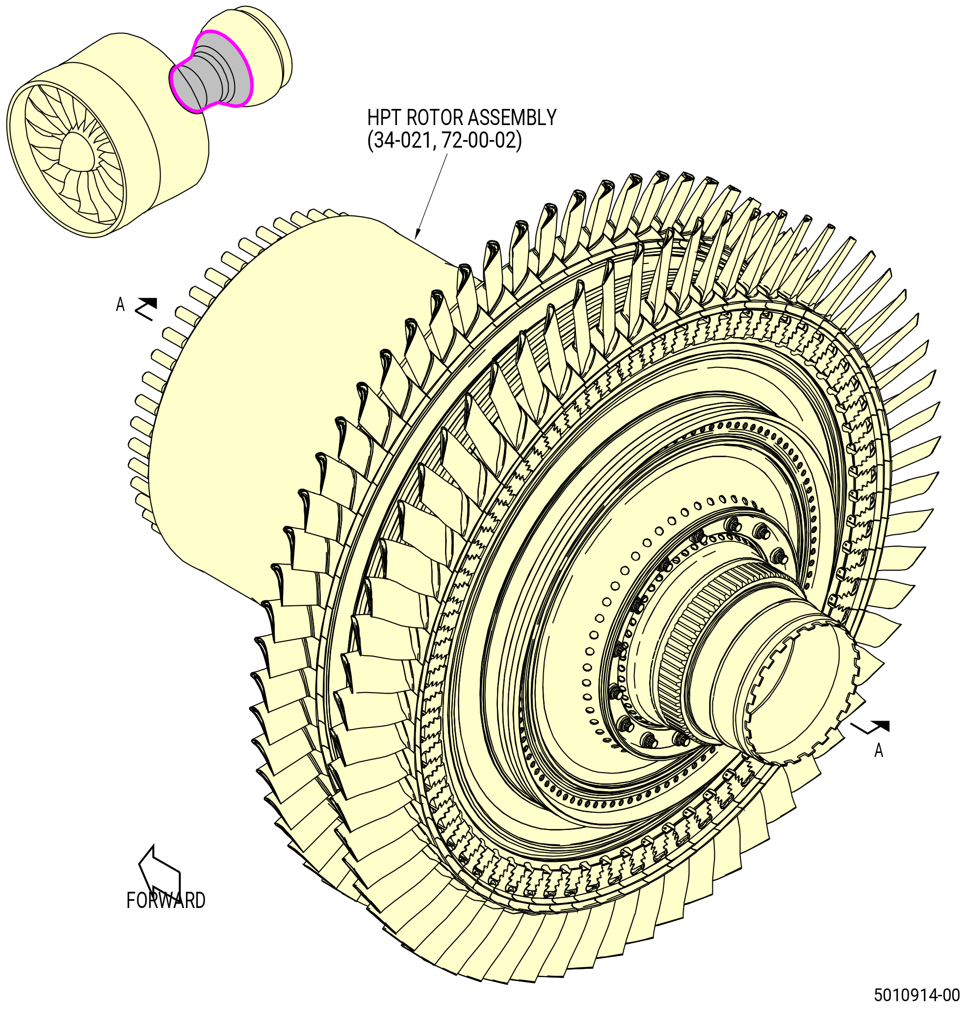
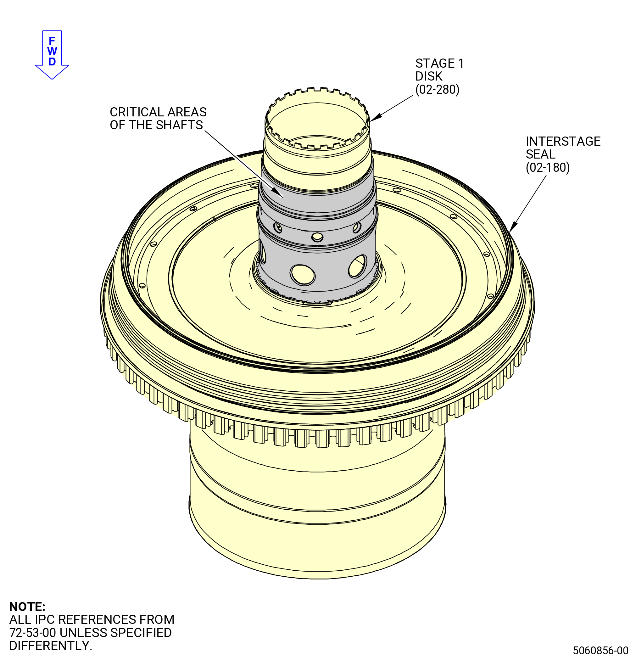
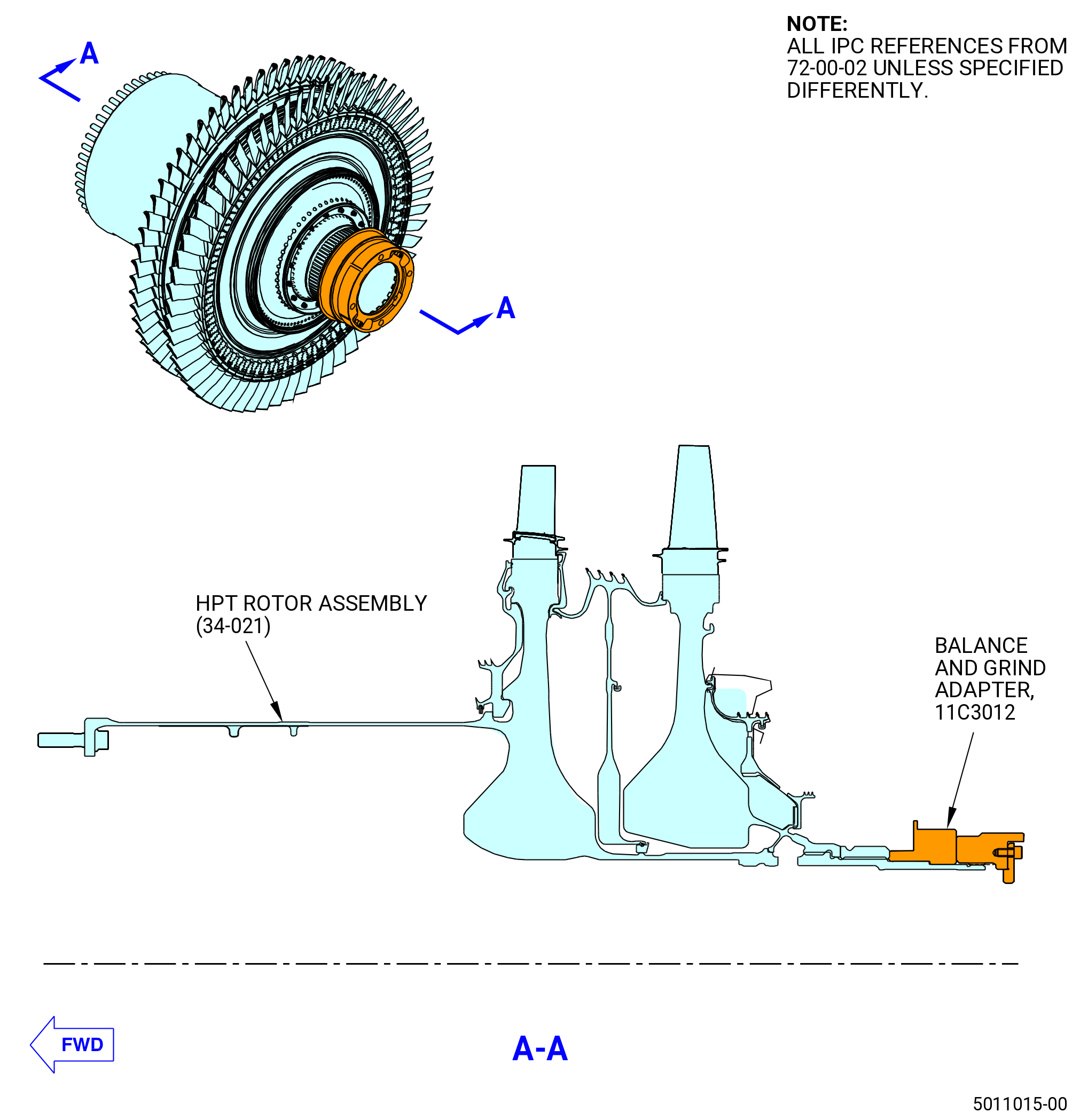
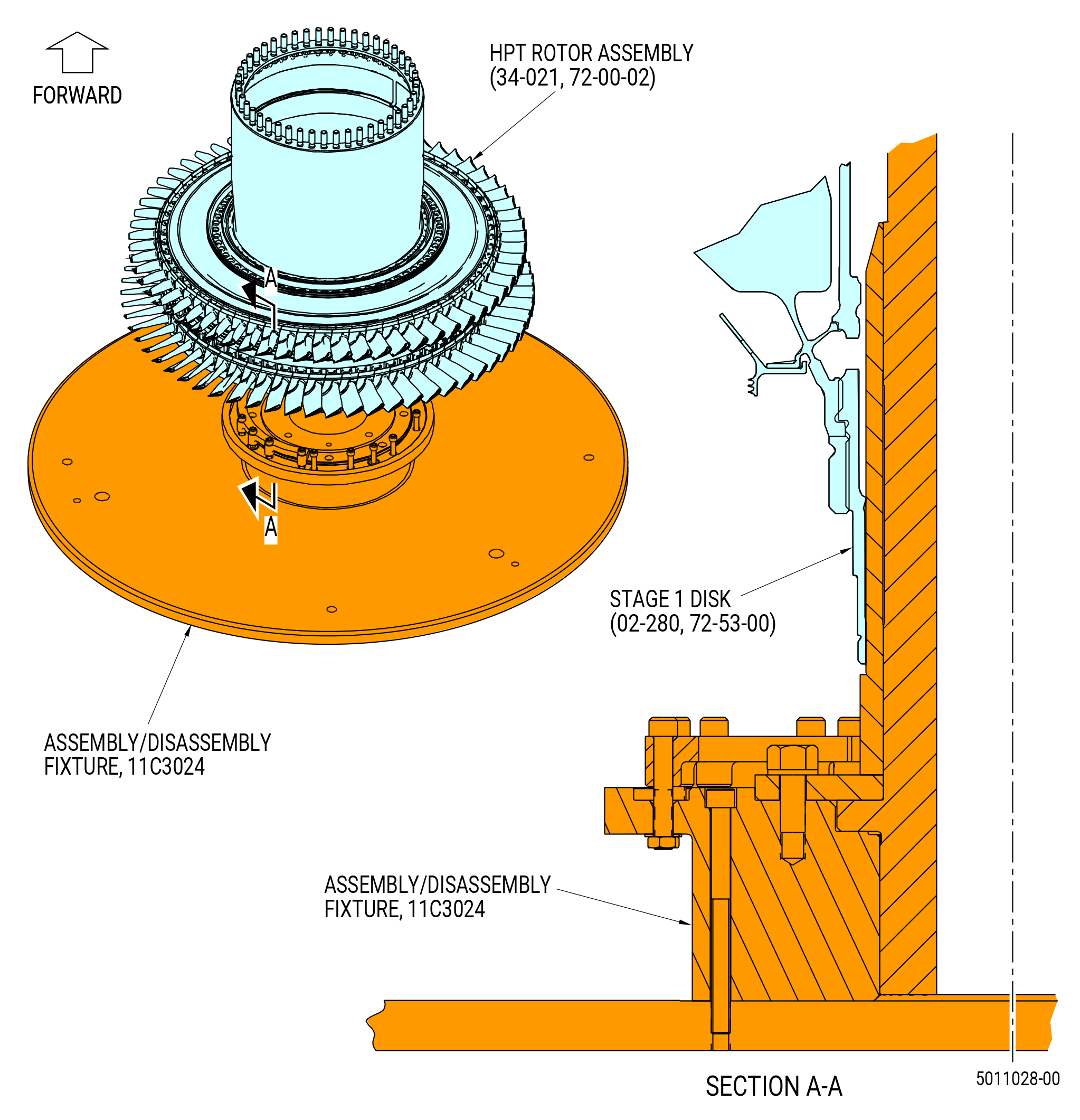
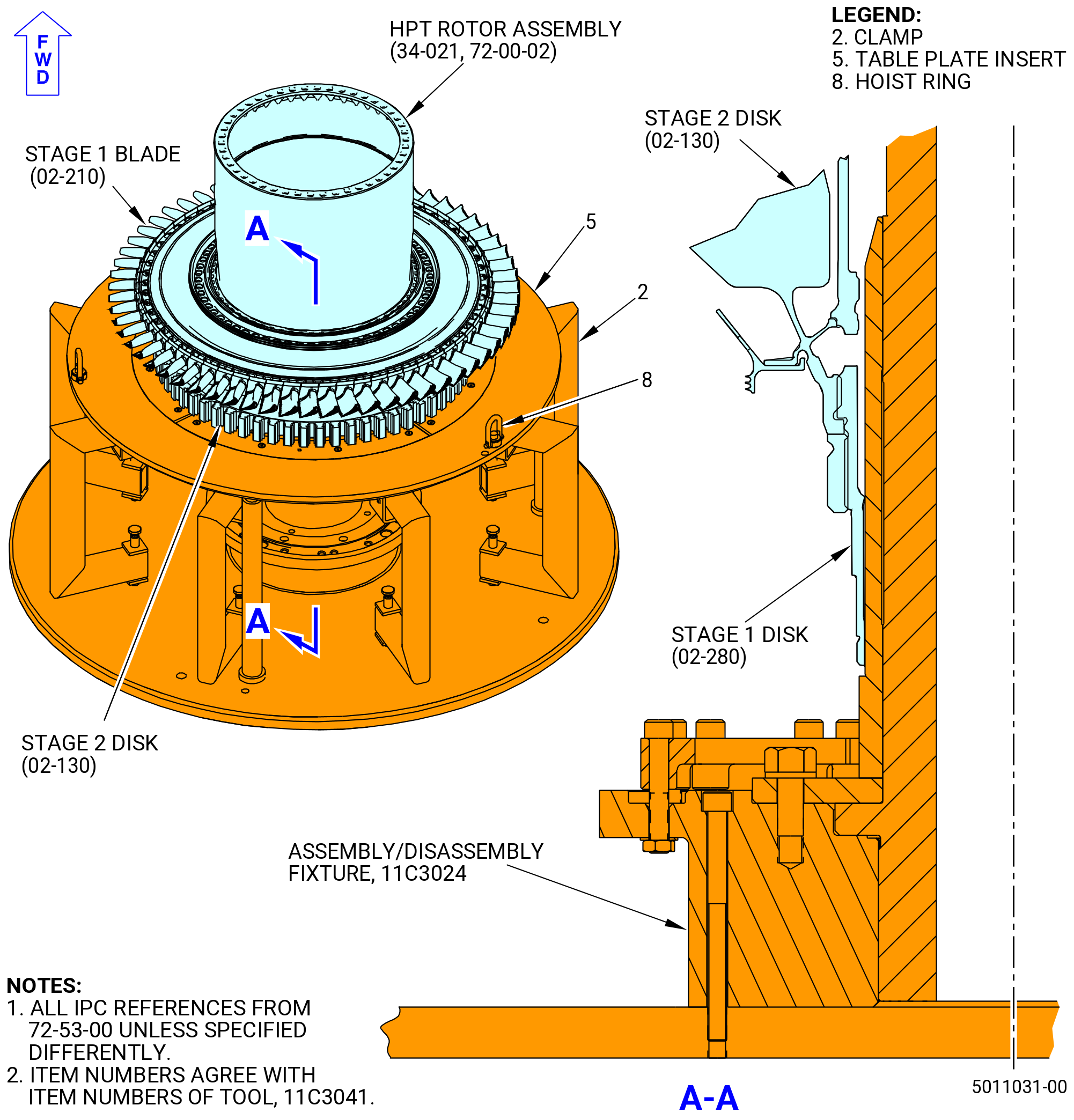
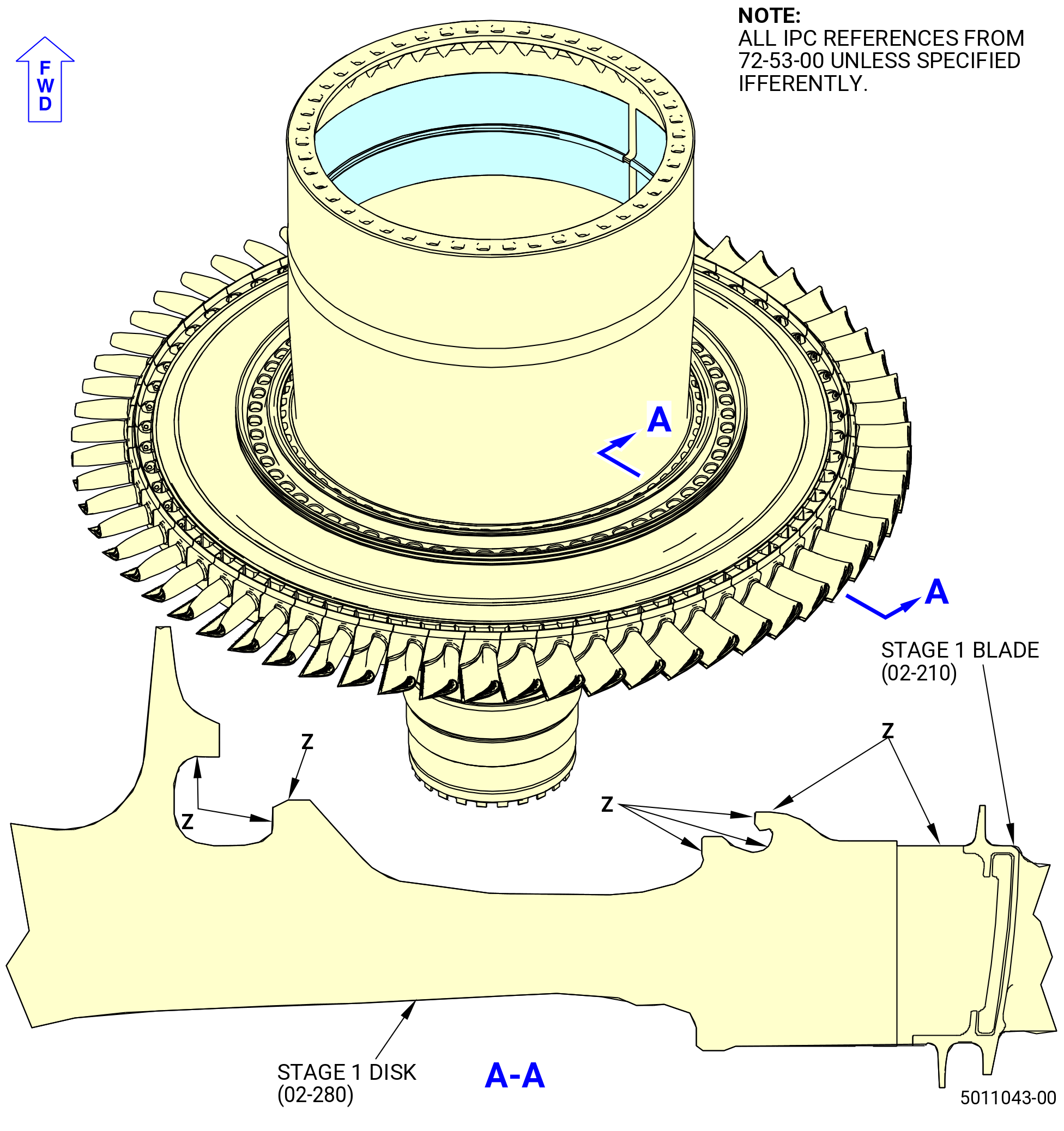
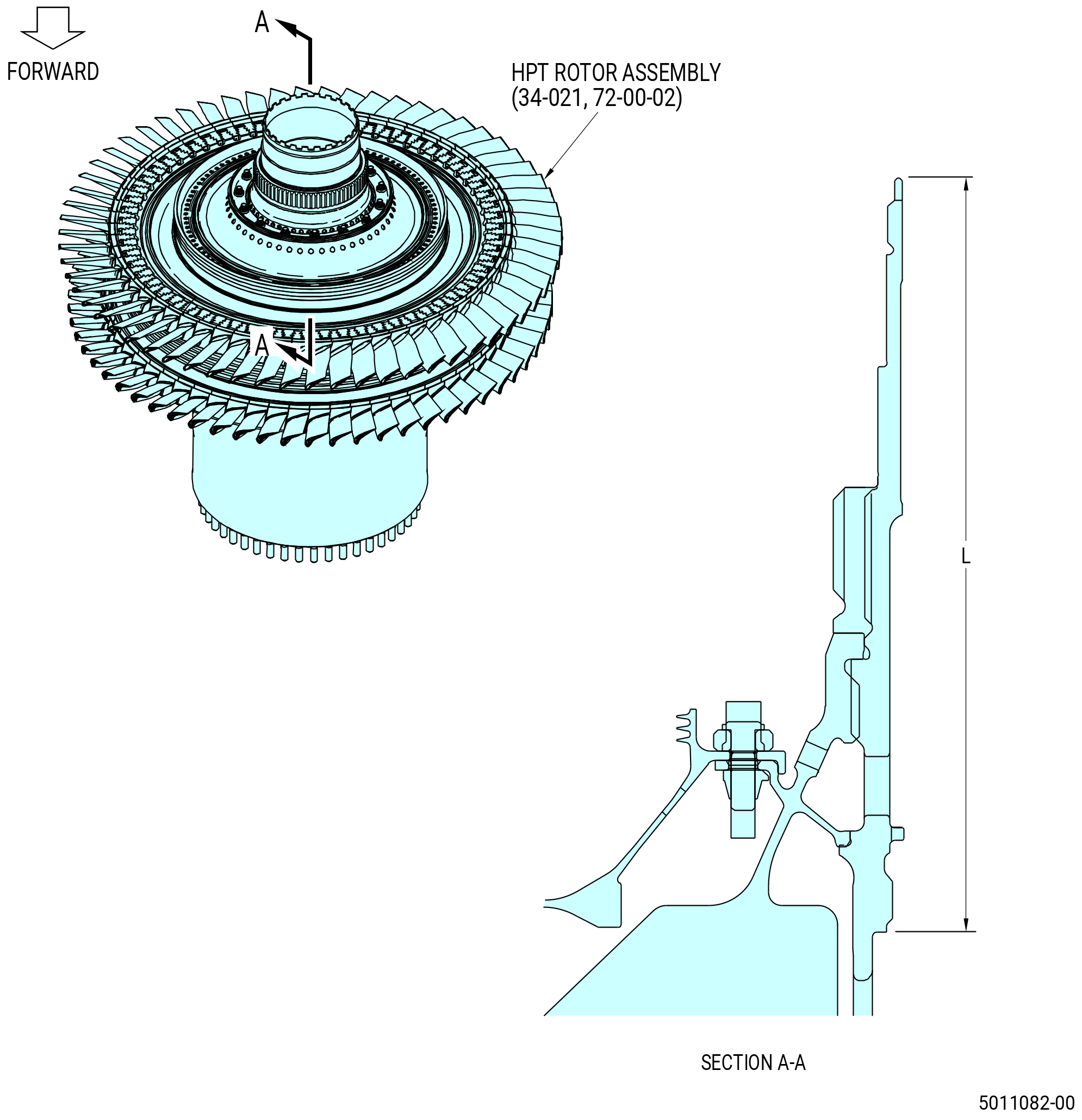
| A. | This procedure gives instructions to assemble the high pressure turbine (HPT) rotor assembly (34-021 , 72-00-02) (SIN 15000). Refer to Figure 1001. |
| B. | Make sure that all personnel read and fully understand this procedure before use. |
| C. | Install protective covers on all assemblies and hardware that will not be used. |
| D. | Install all of the bolts with the heads up or forward unless specified differently. |
| E. | Apply the lubricants to the threads and the friction surfaces only. |
| WARNING: |
|
| F. | Before you do this assembly, make sure that all rabbet and structural flange mating surfaces are clean and free of any foreign material and high metal. If necessary, clean the parts with C04-002 Stoddard solvent, C04-035 isopropyl alcohol, or C04-036 toluene. |
| G. | Follow the instructions to make temporary marking. Refer to TASK 70-16-02-350-017 (TEMPORARY MARKING) . |
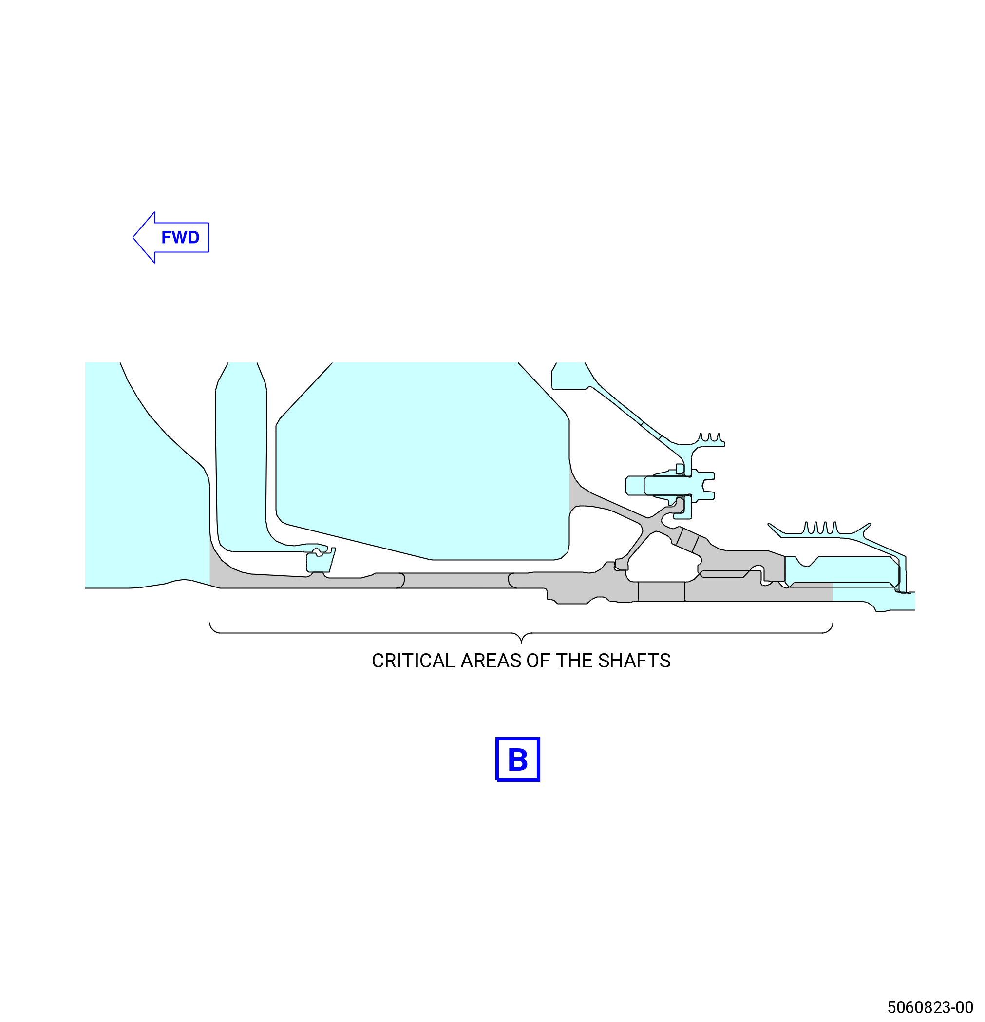
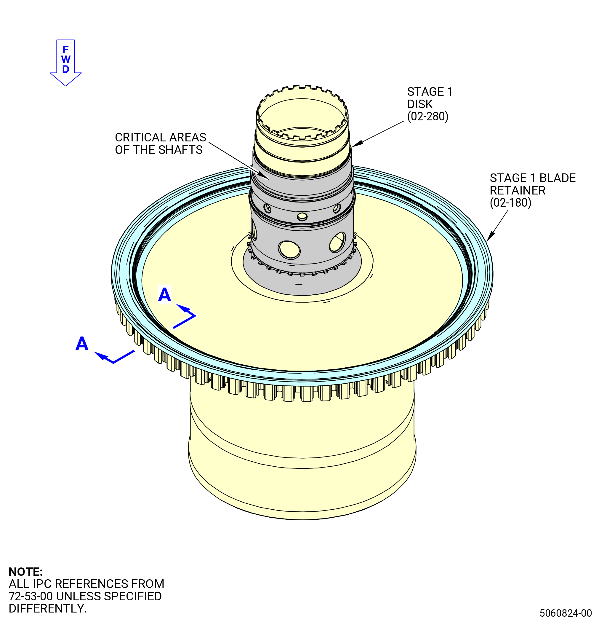
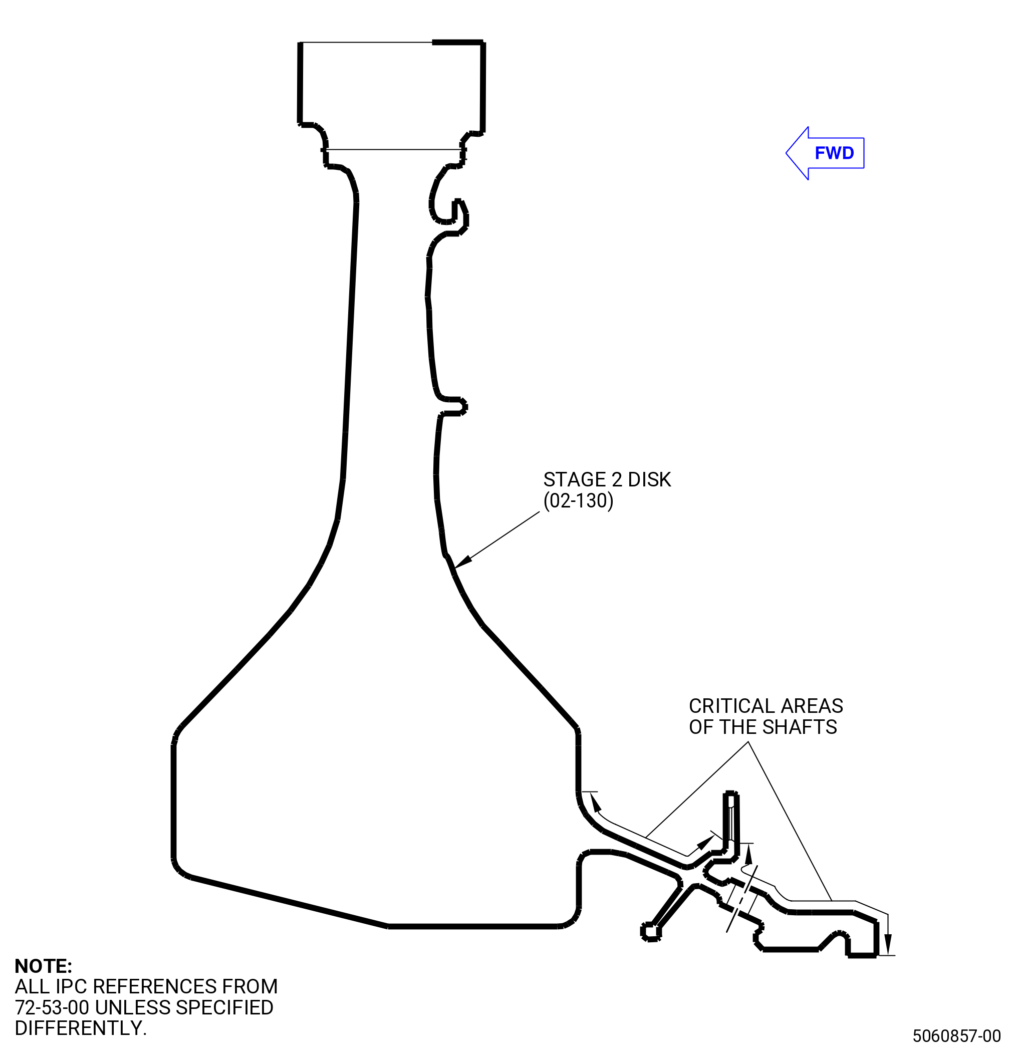
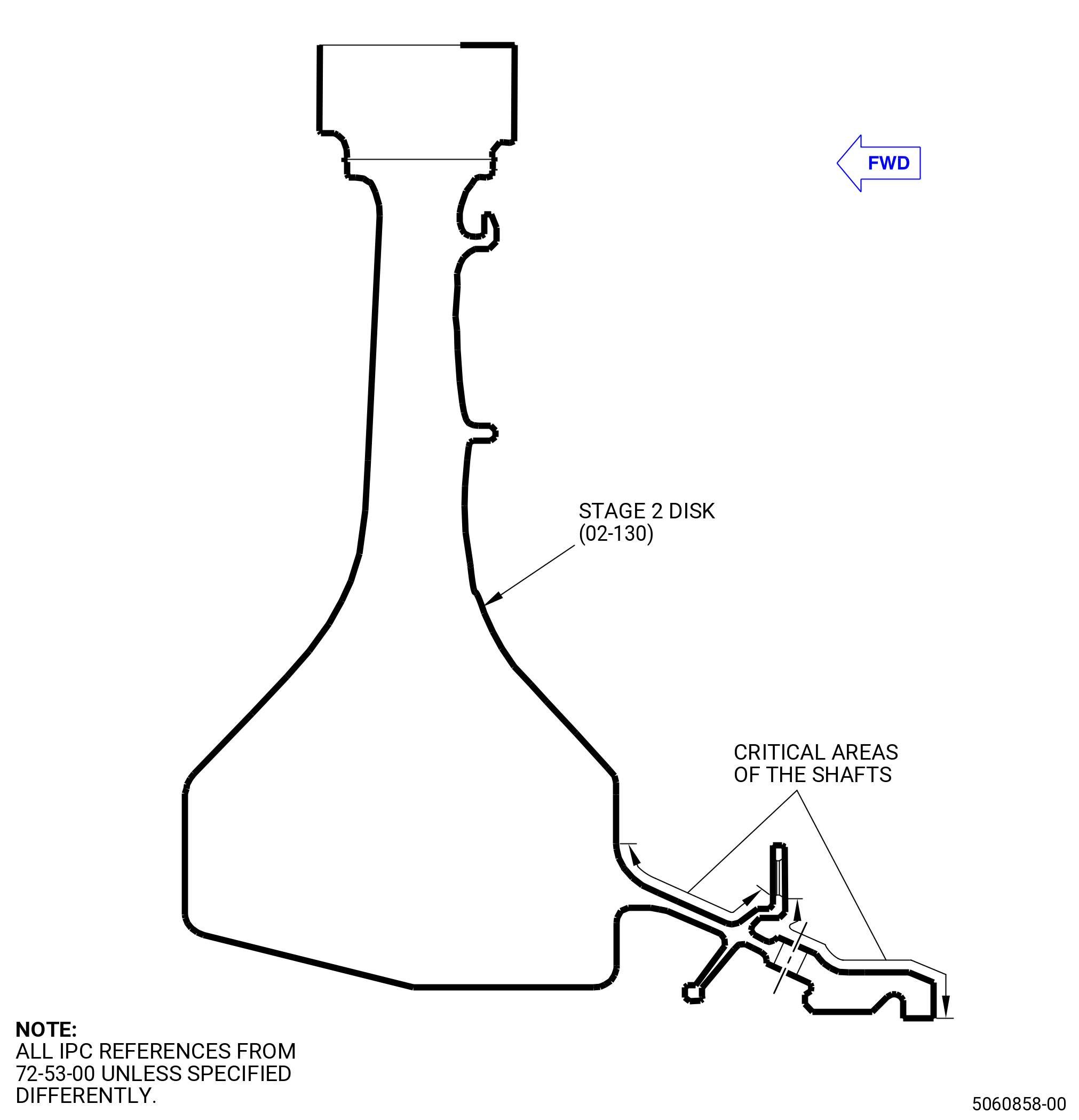
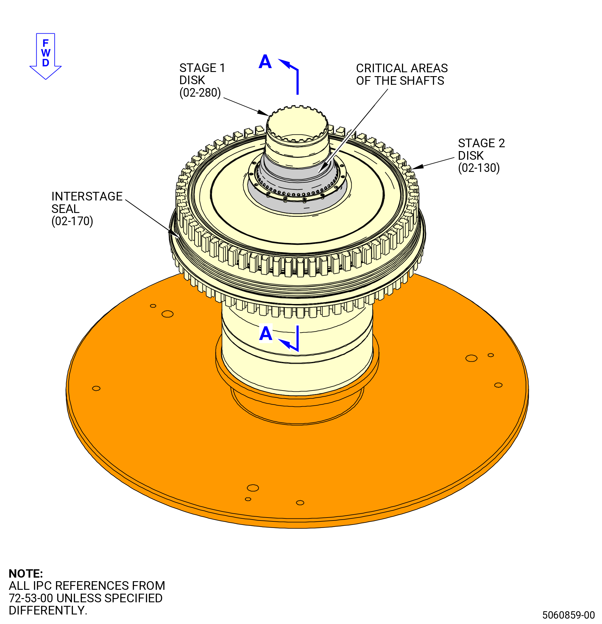
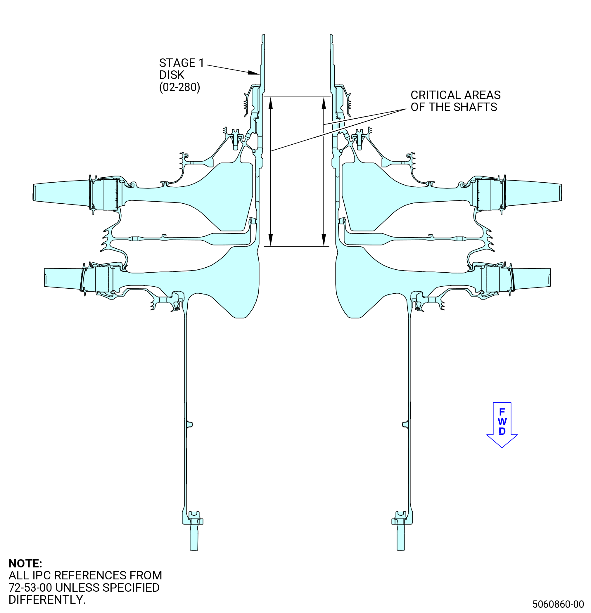
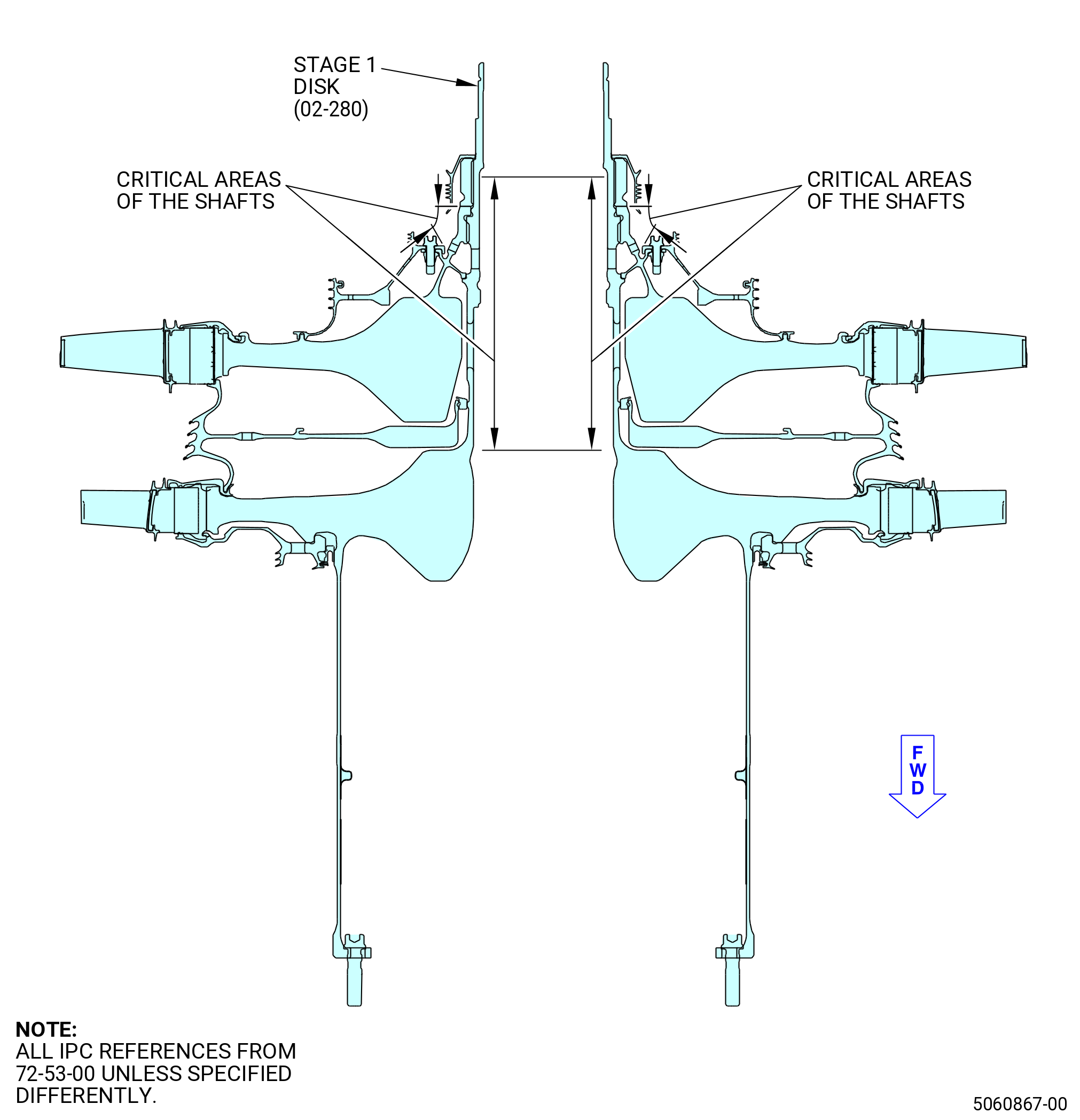
| H. | This assembly contains shafts that are very important. Critical areas of the shafts that require caution and a visual inspection during the assembly procedure, are identified throughout this procedure. Refer to Figure 1001. |
| I. | Make sure that all the mounting areas between life-limited parts and assembly/disassembly fixtures are clean and free from foreign material. |
| 2 . | Tools, Equipment, and Materials. |
| NOTE: |
|
| A. | Tools and Equipment. |
| (1) | Special Tools. |
| (2) | Standard Tools and Equipment. |
|
| (3) | Locally Manufactured Tools. None. |
| B. | Consumable Materials. |
|
| C. | Referenced Procedures. |
|
| D. | Expendable Parts. |
|
| 3 . | Procedure. |
| Subtask 72-53-00-220-185 |
| A. | Deleted. |
| Subtask 72-53-00-220-186 |
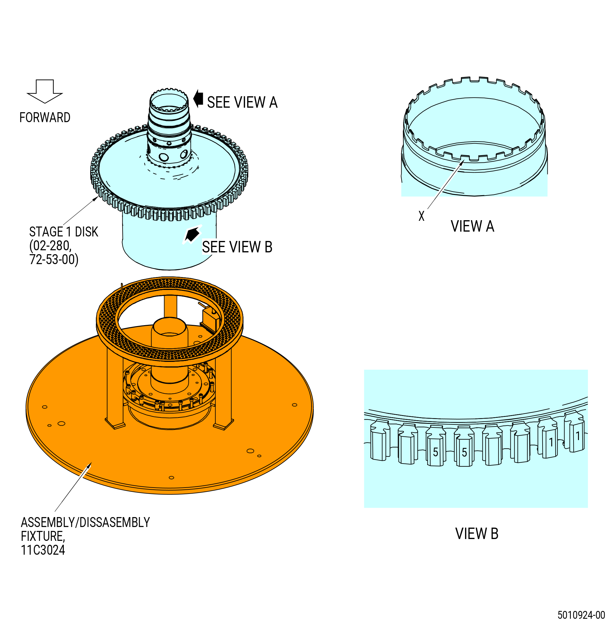
| B. | Make sure that the 11C3024 assembly/disassembly fixture does not have any high metal. Blend as necessary. Refer to TASK 70-42-00-350-002 (BLENDING AND REMOVAL OF HIGH METAL PROCEDURES). |
| Subtask 72-53-00-440-439 |
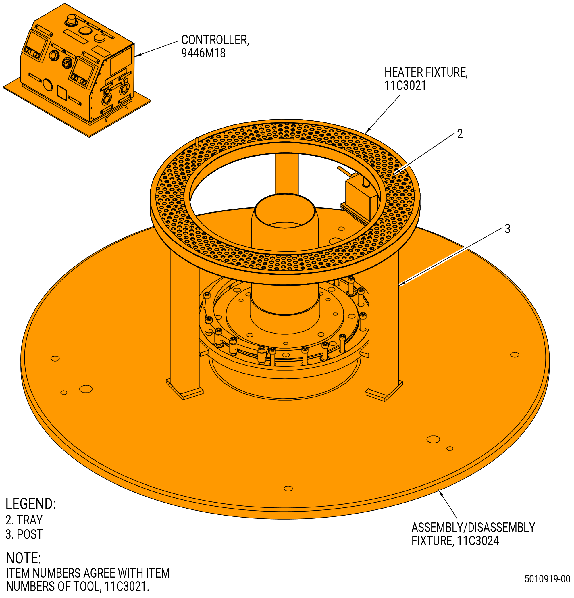
| C. | Install the 11C3021 heater fixture on the 11C3024 assembly/disassembly fixture. |
| Subtask 72-53-00-440-440 |
| CAUTION: |
|
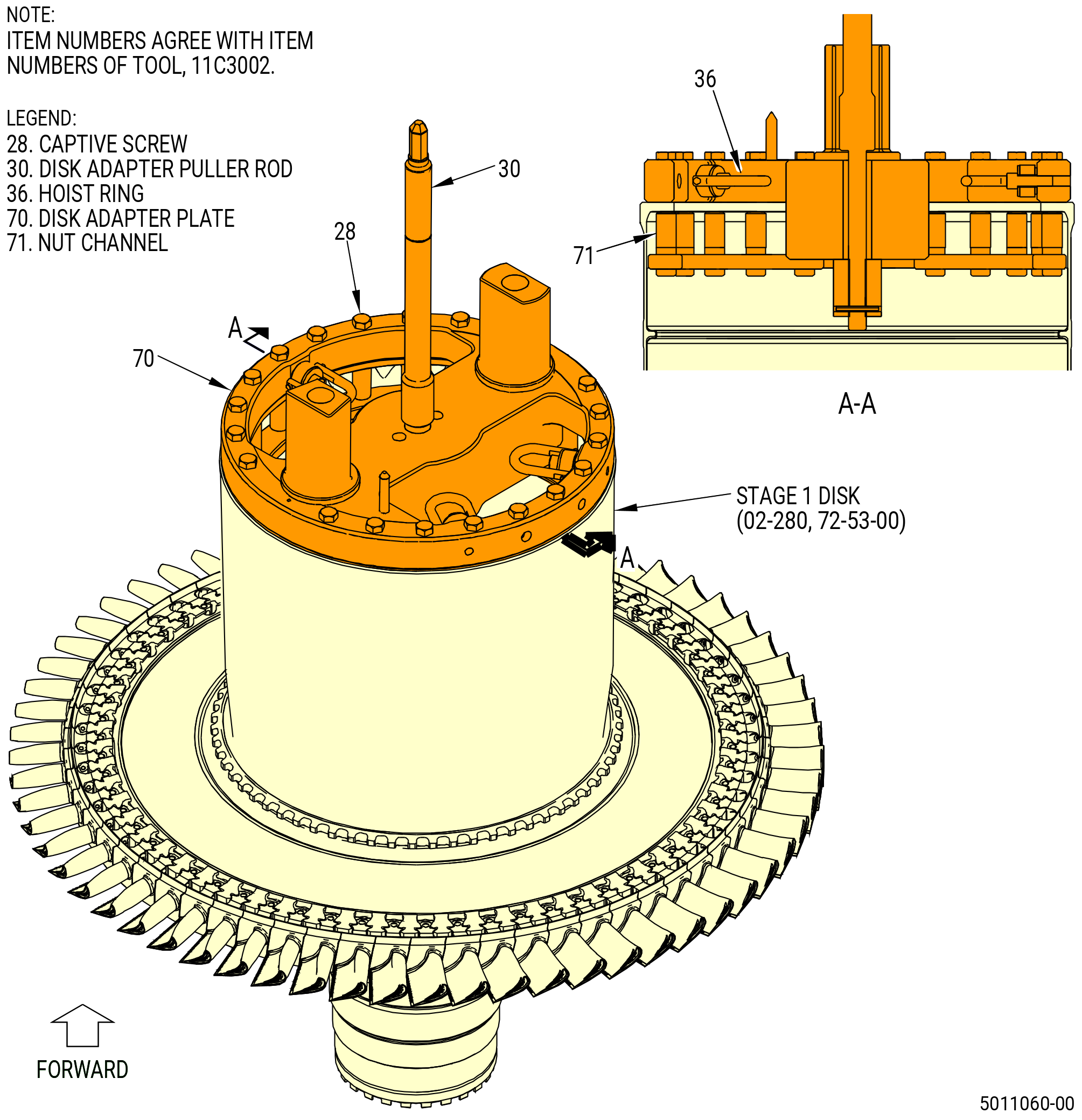
| D. | Prepare the 11C3024 assembly/disassembly fixture. Refer to Figure 1004 and do as follows: |
| (1) | Remove the shaft adapter (item 7) as follows. |
| (a) | Loosen and remove the stress ring (item 6). |
| (b) | Loosen and remove the setscrews (item 15). |
| (c) | Loosen the ring (item 4) to disengage it from the shaft base (item 5). |
| (d) | Loosen the shaft adapter (item 7). |
| WARNING: |
|
| (e) | Attach an overhead hoist to the hoist (item 9) to remove the shaft adapter (item 7) and the ring (item 4) from the shaft base (item 5). |
| Subtask 72-53-00-440-441 |
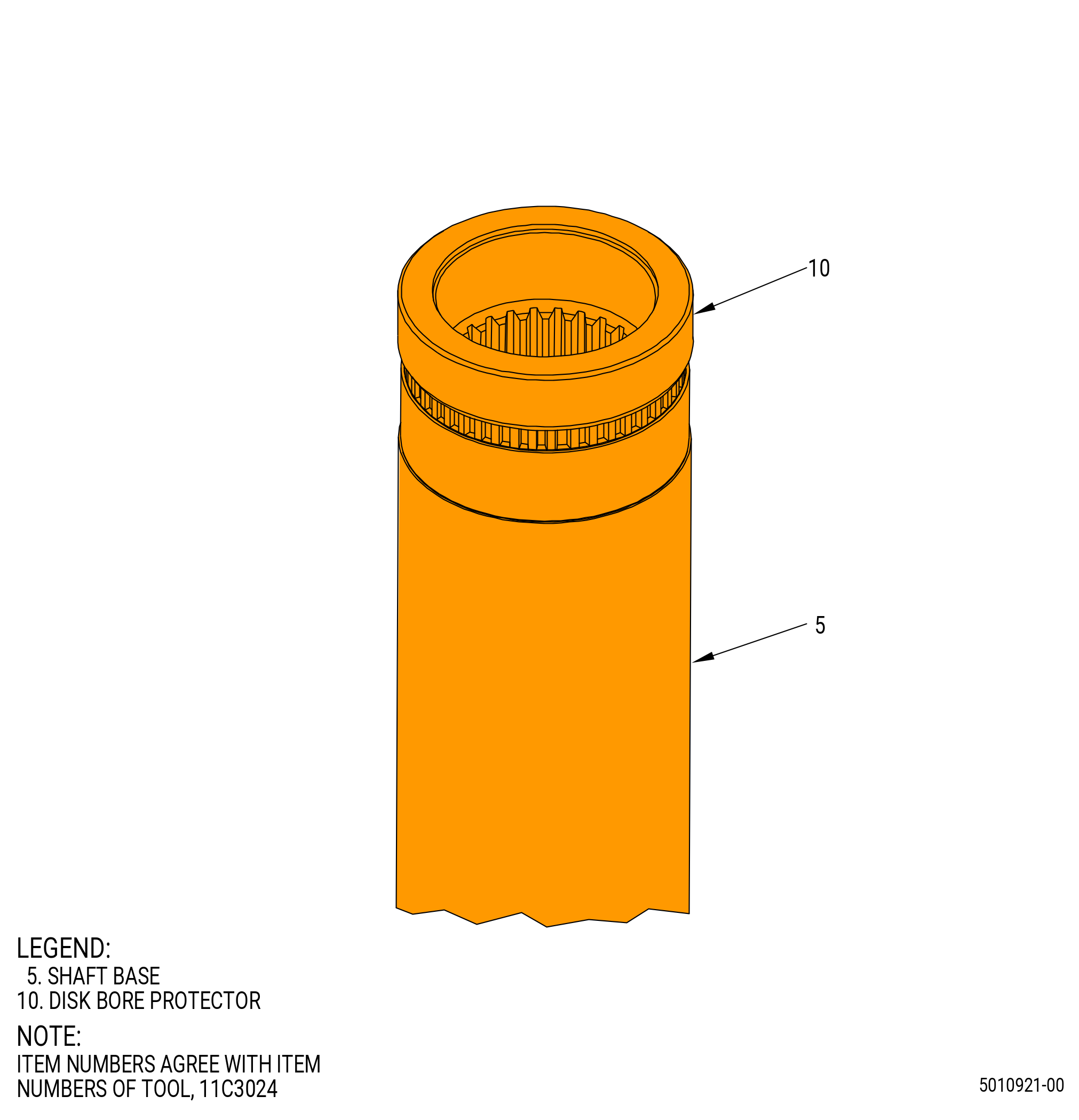
| (2) | Install the disk bore protector (item 10) on the end of the shaft base (item 5) of the 11C3024 assembly/disassembly fixture. Refer to Figure 1005. |
| NOTE: |
|
| (3) | Install the heat element (item 5 or item 6) and the temperature bayonet mount (item 7) on the 11C3021 heater fixture on the tray (item 2). |
| Subtask 72-53-00-440-442 |
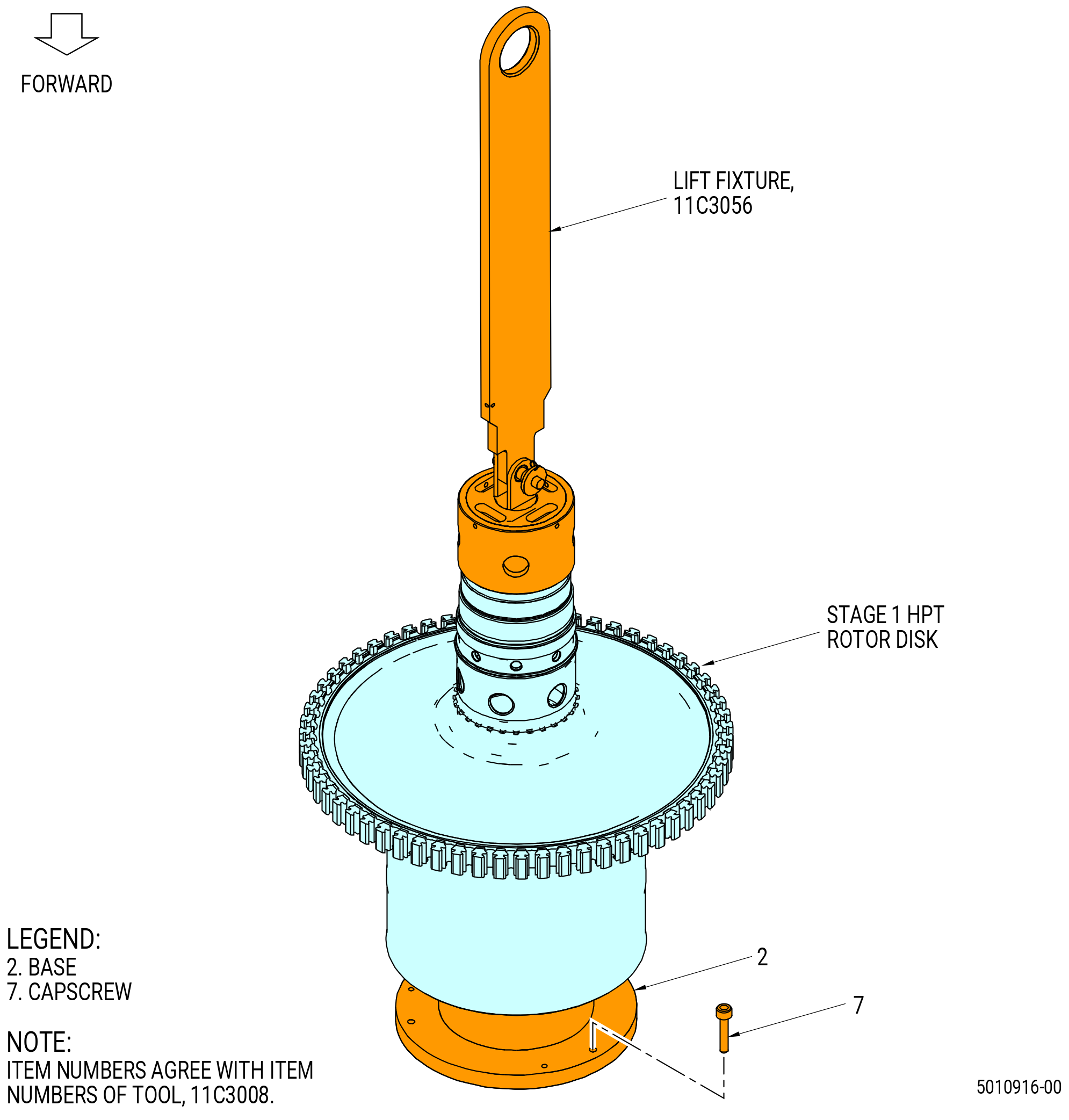
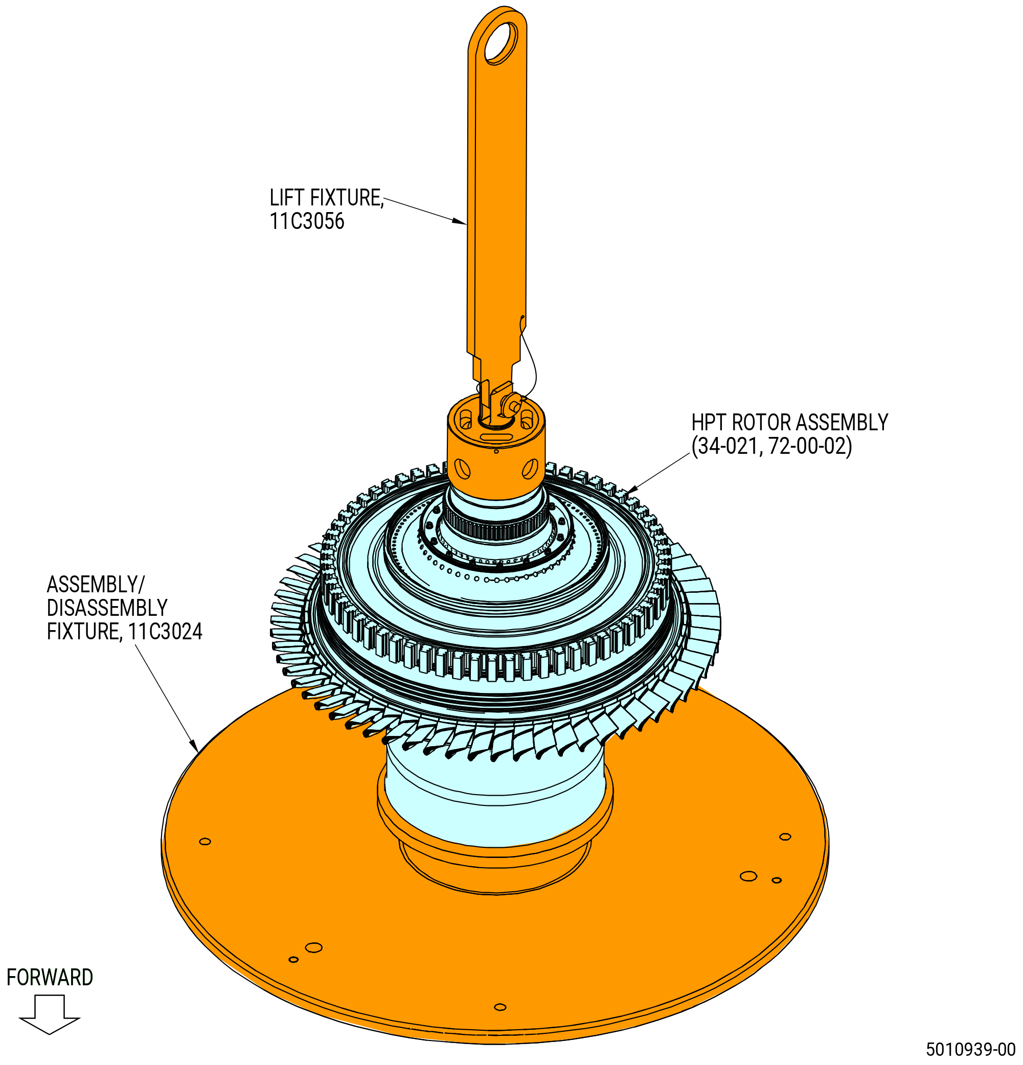
| E. | Install the 11C3056 lift fixture. Refer to Figure 1006 and do as follows: |
| CAUTION: |
|
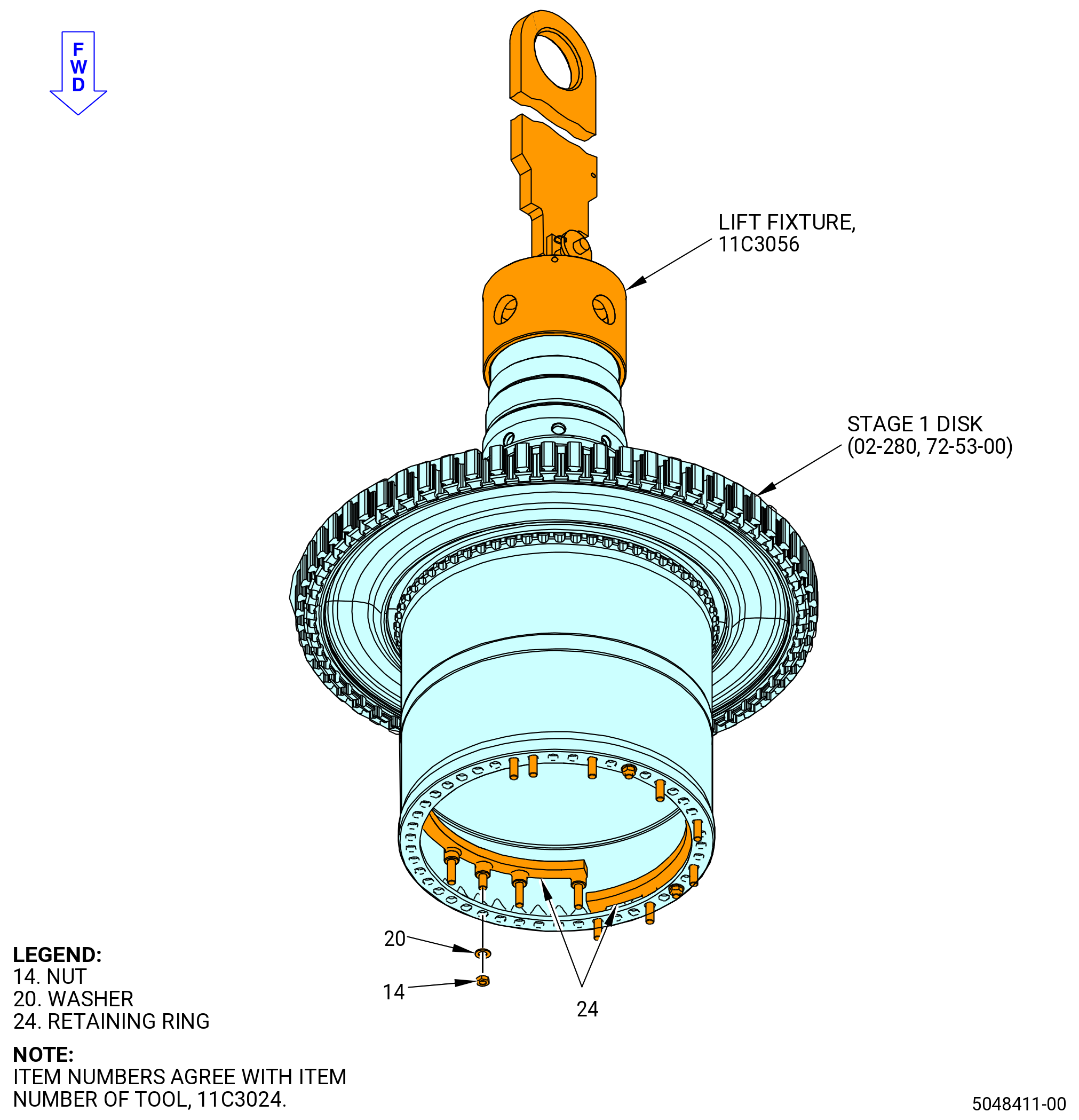
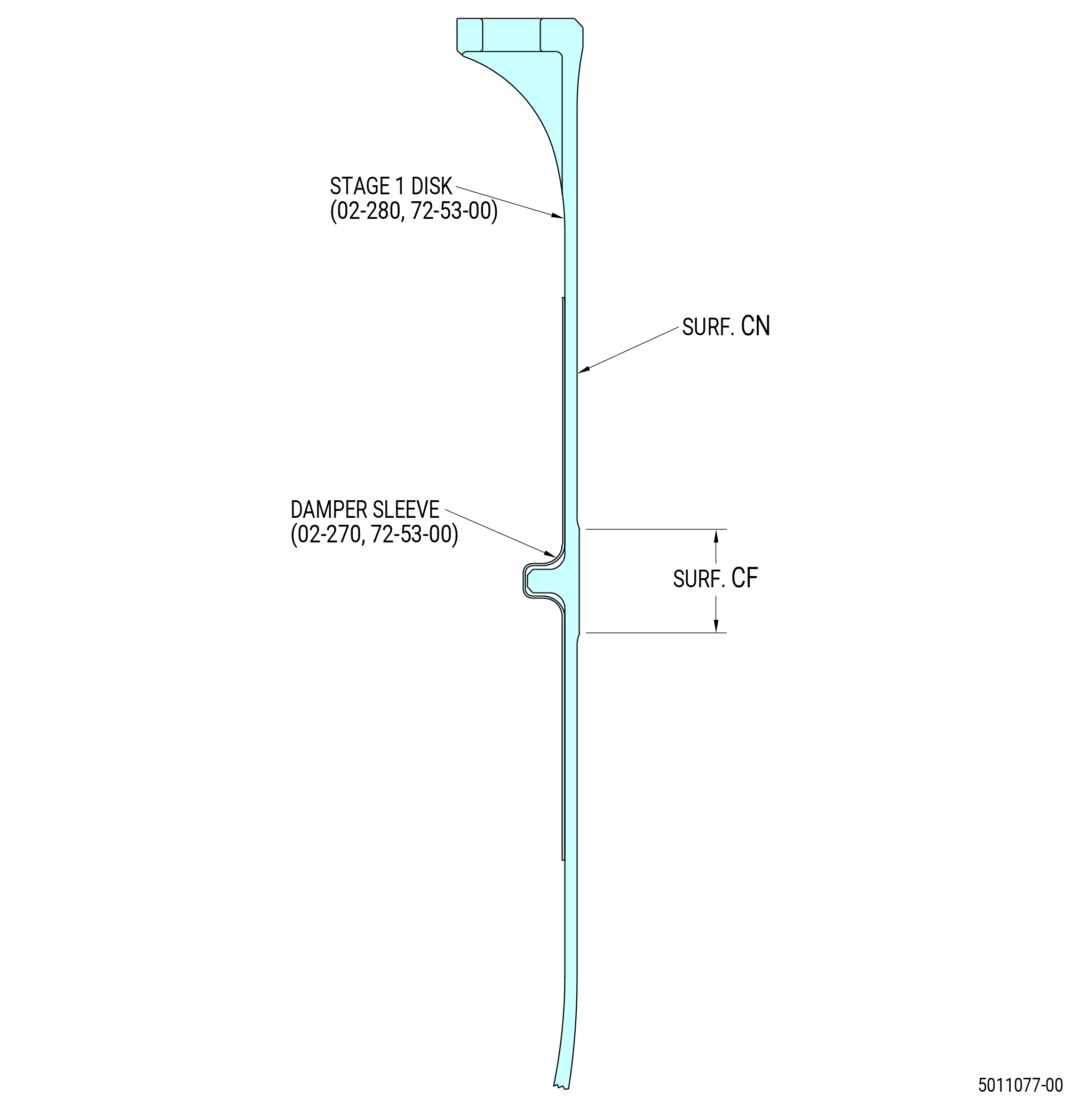
| (1) | Attach the 11C3056 lift fixture to the threads on the aft end of the stage 1 disk (02-280) (SIN 150A1). Turn clockwise (CW), aft looking forward (ALF), until the 11C3056 lift fixture is fully engaged on the HPT rotor shaft. |
| (2) | Attach an overhead hoist to the 11C3056 lift fixture. |
| Subtask 72-53-00-440-443 |
| CAUTION: |
|
| F. | Attach the stage 1 disk (02-280) (SIN 150A1) to the 11C3024 assembly/disassembly fixture and do as follows: |
| WARNING: |
|
| (1) | Clean the areas where the HPT rotor stage 1 disk (02-280) (SIN 150A1) will touch the 11C3024 assembly/disassembly fixture with C04-035 isopropyl alcohol. |
| (2) | Make sure that you can see SP mark on the stage 1 disk (02-280) (SIN 150A1). If not, use a C05-003 marking pen to make it easier to see. |
| WARNING: |
|
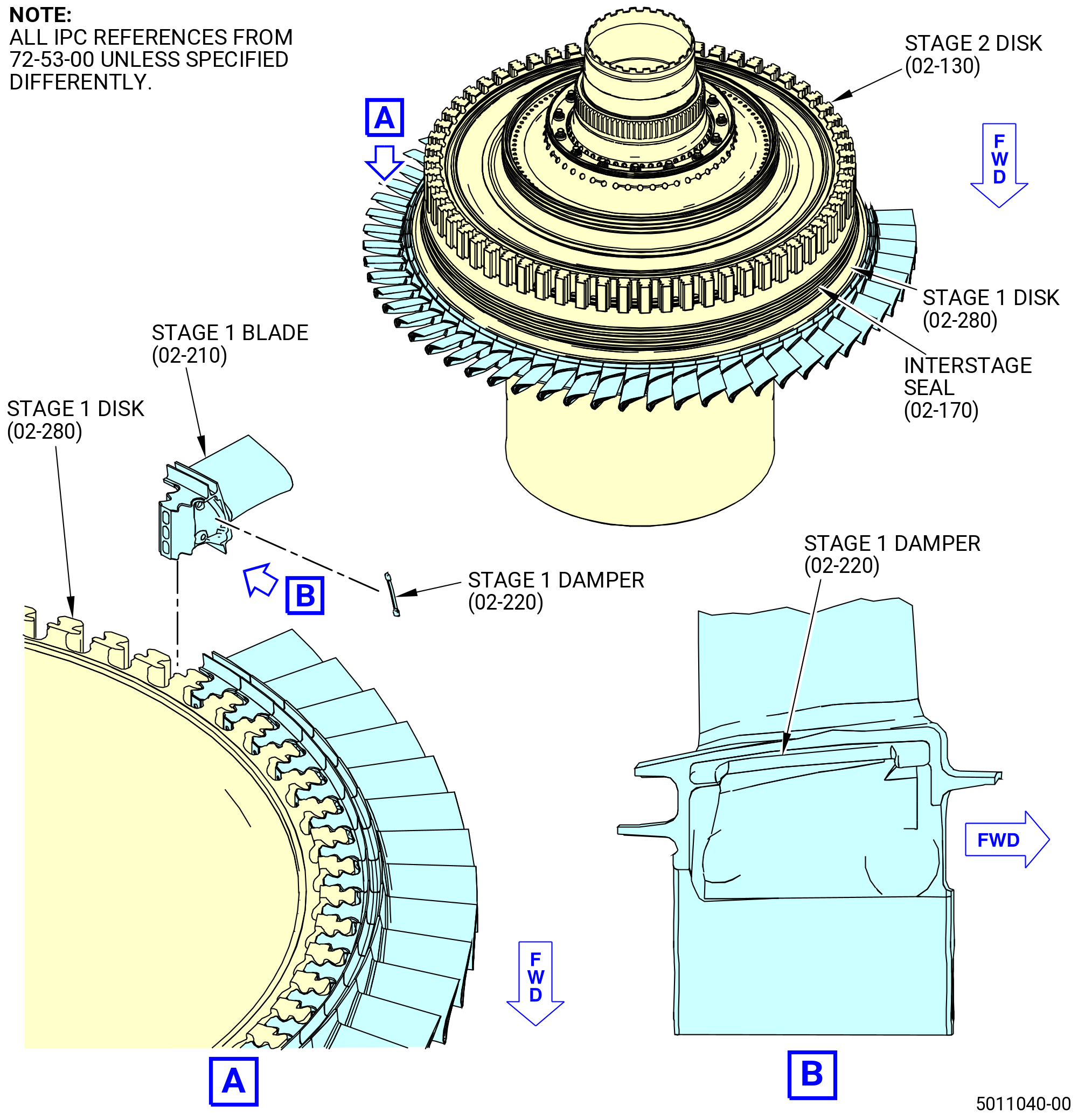
| (3) | Lift the stage 1 disk and install the retaining ring segments (item 24) on the aft face of the forward flange. Refer to Figure 1006. |
| (4) | Install the tray (item 2) and post (item 3) of the 11C3021 heater fixture onto the 11C3024 assembly/disassembly fixture. Refer to Figure 1004. |
| WARNING: |
|
| (5) | Apply C02-058 lubricant to the threads of the nuts (item 14) and the faces of the washers (item 20). |
| (6) | Install a washer (item 20) and a nut (item 14) on each of the four short studs of the retaining ring (item 24). |
| (7) | Torque the nuts (item 14) to 276-324 lb in. (31-37 N.m). |
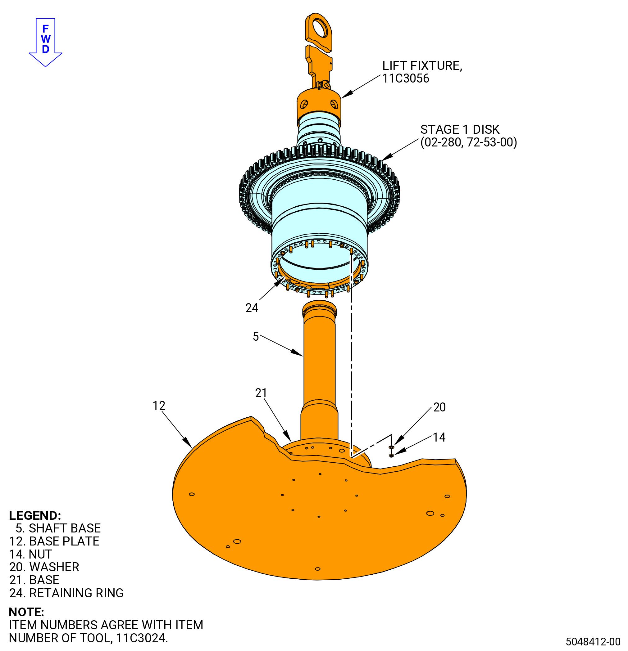
| (8) | Align the four short studs with the large holes in the base (item 21). Refer to Figure 1007. |
| (9) | Lower the stage 1 disk and attach the forward flange to the 11C3024 assembly/disassembly fixture and do as follows: |
| WARNING: |
|
| (a) | Apply C02-058 lubricant with a C10-108 brush to the threads of the retaining ring (item 24), the faces of the washers (item 20), and the nuts (item 14). |
| (b) | Attach 12 washers (item 20) and 12 nuts (item 14) to the studs of the retaining ring (item 24). |
| (c) | Torque the nuts (item 14) to 276-324 lb in. (31-37 N.m) in a criss-cross pattern. Continue this procedure until all of the nuts are tight. |
| (10) | Remove the 11C3056 lift fixture. Refer to Figure 1006. |
| (11) | Use a C05-003 marking pen to mark in a clockwise (CW) direction aft looking forward (ALF) of the stage 1 disk the position of the 1-1 and 5-5 disk post. Refer to Figure 1008. |
| (12) | Use a C05-003 marking pen to remark the X stamped from vendor on the aft shaft of the stage 1 disk. |
| Subtask 72-53-00-440-444 |
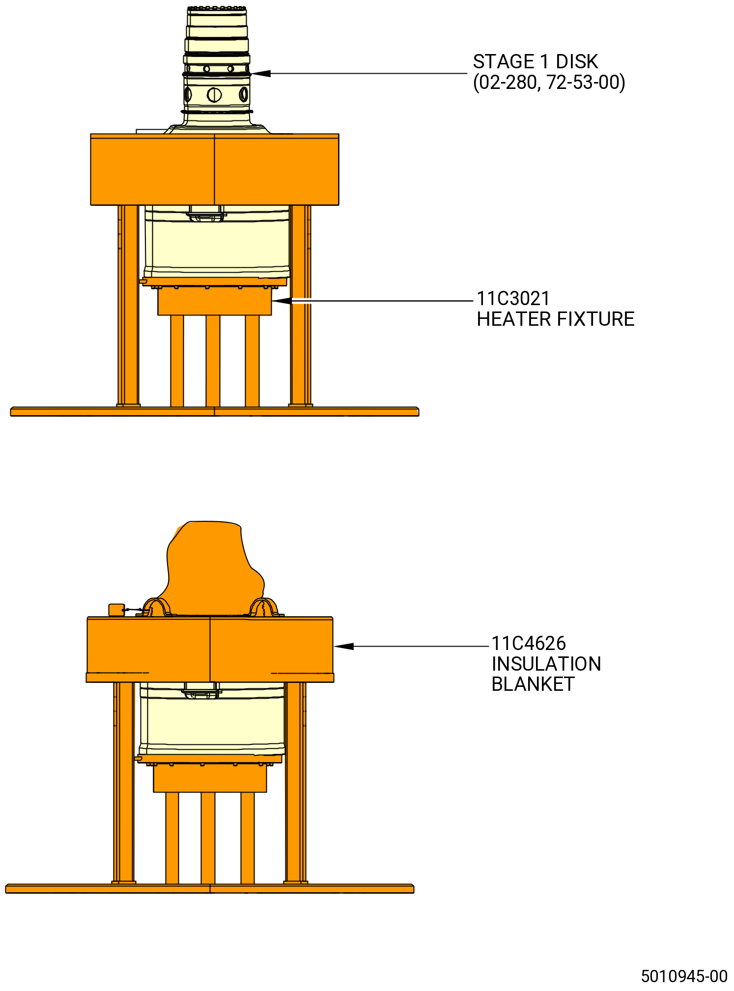
| G. | Heat the stage 1 disk (02-280) (SIN 150A1). Refer to Figure 1009 and do as follows: |
| WARNING: |
|
| (1) | Connect the 9446M18 controller. |
| (2) | Install the 11C4626 insulation blanket. Refer to Figure 1009. |
| CAUTION: |
|
| (3) | Heat the stage 1 disk (02-280) (SIN 150A1) at the rabbet to 500°F (260°C) with a maximum temperature of 700°F (371°C). Check with a calibrated temperature probe to make sure that the temperature is not more than the maximum limit. |
| Subtask 72-53-00-440-445 |
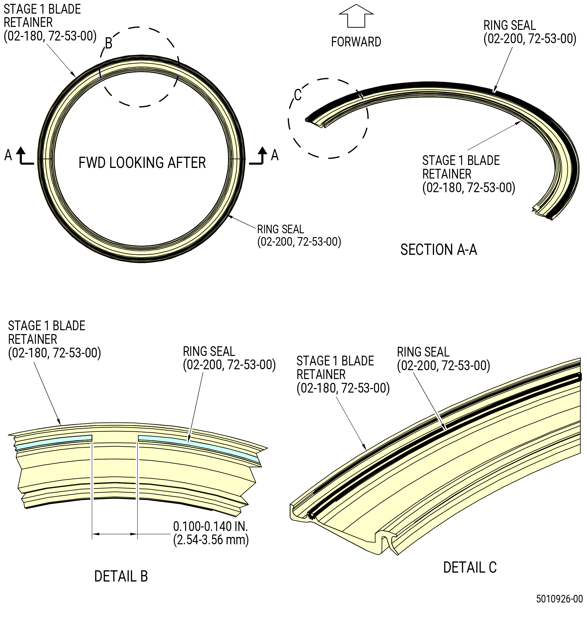
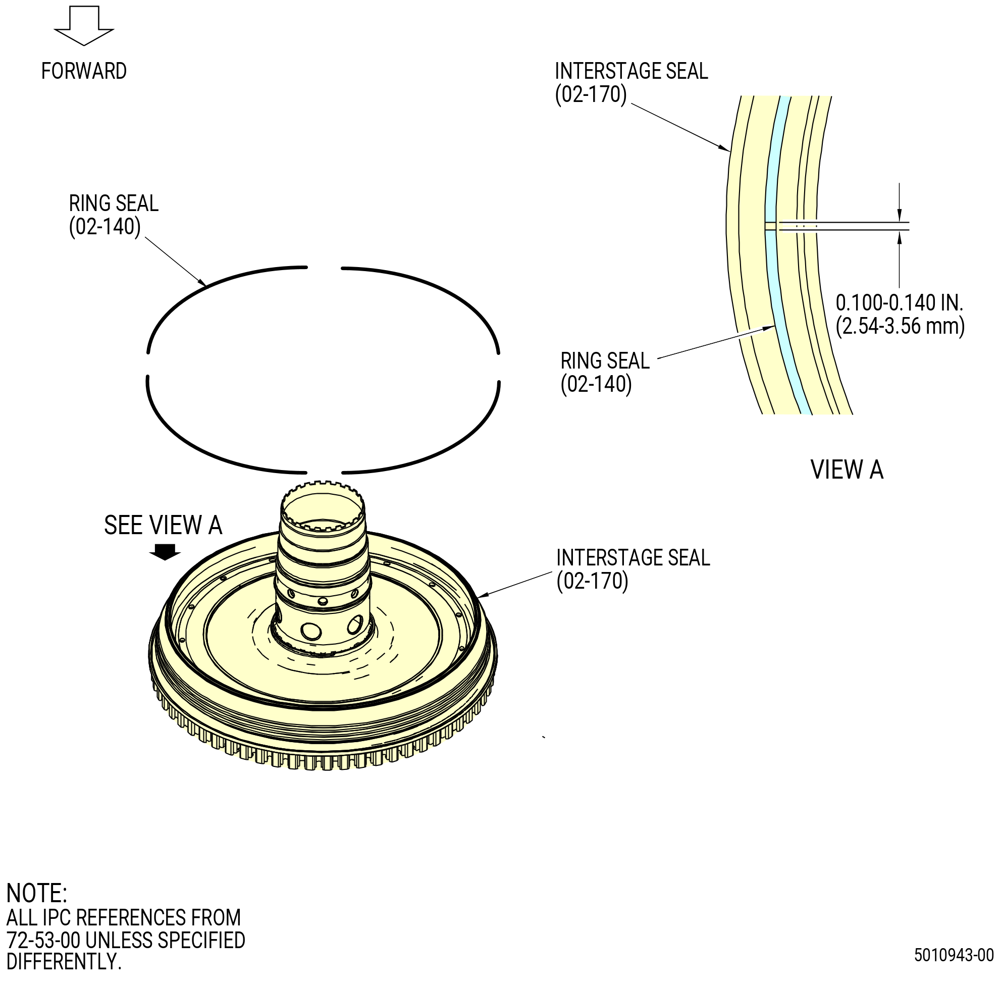
| H. | Install the ring seal (02-200) (SIN 150N2) into the groove on the stage 1 blade retainer (02-180) (SIN 150BB). Refer to Figure 1010 and do as follows: |
| (1) | Put the stage 1 blade retainer (02-180) (SIN 150BB), forward end up, on a work table. |
| (2) | Do a visual inspection of the stage 1 blade retainer (02-180) (150BB) for nicks and high metal. |
| WARNING: |
|
| (3) | Clean the stage 1 blade retainer with C04-035 isopropyl alcohol. |
| (4) | Cut four ring seal segments to 20.0 inches (508 mm) in length. |
| (5) | Use a file to remove unwanted material from the ends of the ring seal segments. Make sure that there are no burrs on the segments. |
| (6) | Put a ring seal segment into the groove in the forward face of the stage 1 blade retainer. Apply C10-012 tape to hold it in position, then, install the next segment. Keep an end gap of 0.100-0.140 inch (2.54-3.56 mm). |
| (7) | Repeat this procedure until all four of the ring seal segments are installed. Cut the segments as necessary to keep an end gap of 0.100-0.140 inch (2.54-3.56 mm). |
| Subtask 72-53-00-220-187 |
| (8) | Measure the distances between the ends of the ring seal segments as follows: |
| (a) | If the distance is more than 0.140 inch (3.56 mm), install a new ring seal segment. |
| (b) | If the distance is less than 0.100 inch (2.54 mm), remove a part of the ring seal segment. |
| (9) | Remove the C10-012 tape and the ring seal segments from the blade retainer. |
| WARNING: |
|
| (10) | Apply small amounts of C01-027 synthetic adhesive or C01-037 synthetic adhesive into the groove in the aft face of the stage 1 blade retainer (02-180) (SIN 150BB). |
| (11) | Allow the adhesive to cure for 15-20 minutes until it is tacky. |
| NOTE: |
|
| (12) | Install the ring seal segments into the groove in the forward face of the stage 1 blade retainer (02-180) (SIN 150BB). |
| (13) | Make sure that the ring seal segments are fully in the groove of the blade retainer. |
| (14) | Measure the distances between the ends of the ring seal segments to make sure that they are 0.100-0.140 inch (2.54-3.56 mm). |
| Subtask 72-53-00-440-446 |
| CAUTION: |
|
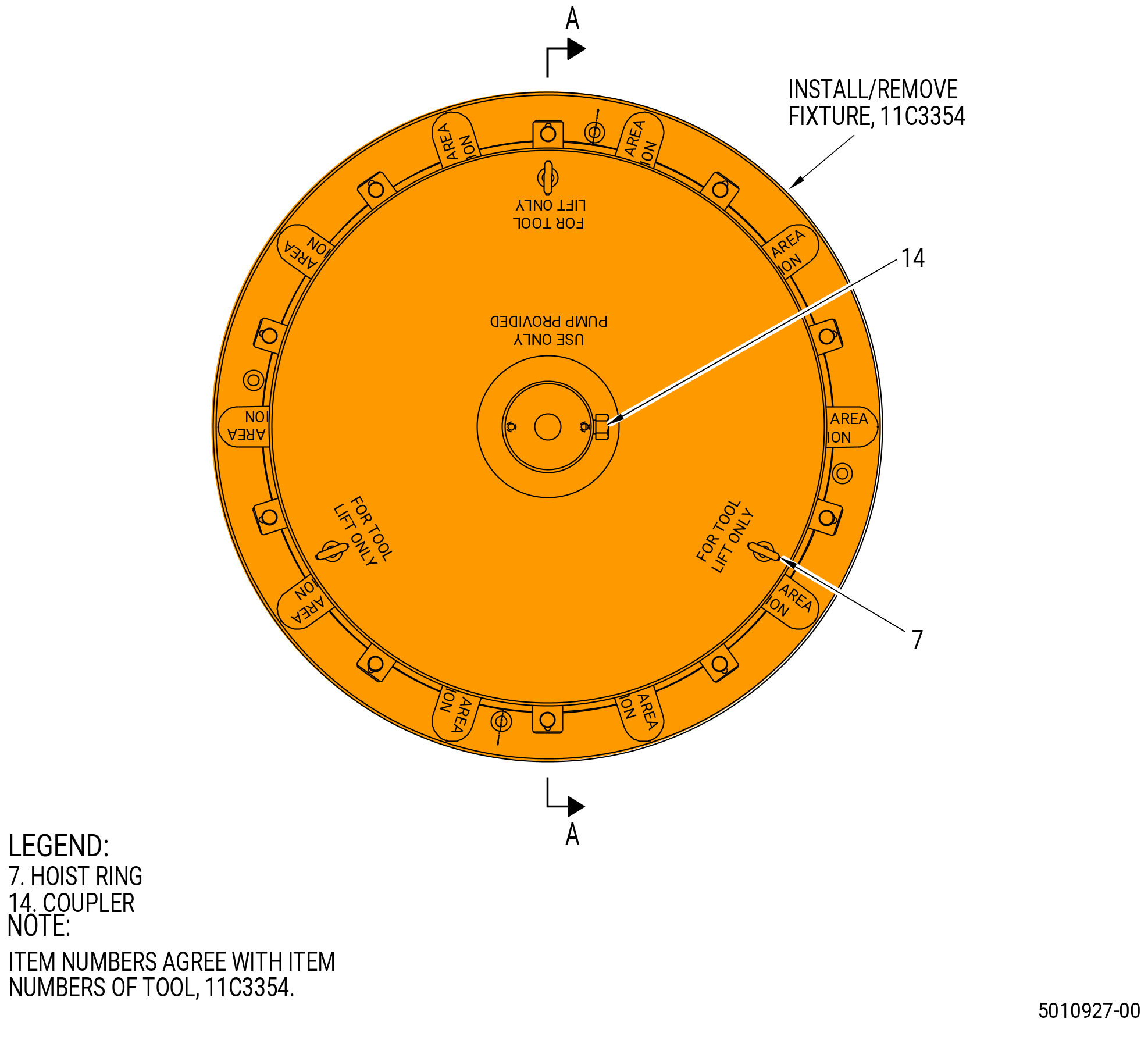
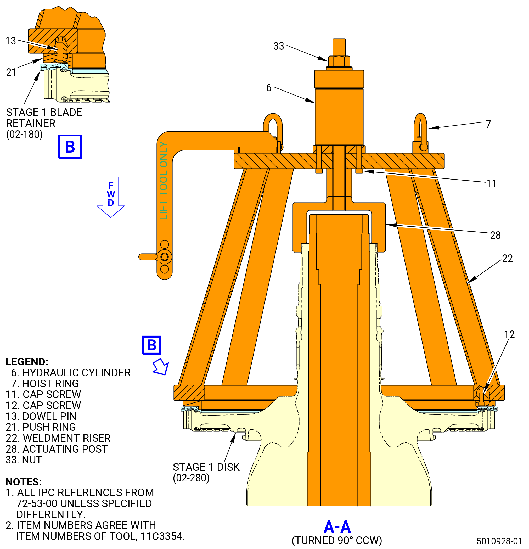
| I. | Install the stage 1 blade retainer (02-180) (SIN 150BB) on the stage 1 disk (02-280) (SIN 150A1) with the 11C3354 install/remove fixture. Refer to Figure 1012 and do as follows: |
| WARNING: |
|
| (1) | Put the stage 1 blade retainer (02-180) (SIN 150BB) forward end down and cover it with dry ice and chill for 25 minutes. |
| WARNING: |
|
| (2) | Attach an overhead hoist to the hoist (item 9) of the 11C3024 assembly/disassembly fixture. Refer to Figure 1004. |
| (3) | Use an overhead hoist and lower the adapter shaft (item 7) and install it on the stage 1 disk. |
| (4) | Attach an overhead hoist to the 11C3354 install/remove fixture and move it on the stage 1 disk and prepare to install it. |
| WARNING: |
|
| WARNING: |
|
| (5) | Pour liquid nitrogen on the stage 1 blade retainer (02-180) (SIN 150BB) and allow it to sit for 1 minute. |
| (6) | Install the stage 1 blade retainer (02-180) (SIN 150BB) it on the aft side of the stage 1 disk by hand. |
| (7) | Quickly lower and install the 11C3354 install/remove fixture on the stage 1 blade retainer (02-180) (SIN 150BB). |
| (a) | Install the push ring (item 21) onto the adapter shaft (item 7) of the 11C3024 assembly/disassembly fixture. |
| WARNING: |
|
| (b) | Apply 4000 psi (27579 Kpa) of hydraulic pressure into the actuator. |
| (8) | Let the parts go back to ambient temperature. |
| (9) | Remove the 11C3354 install/remove fixture. Refer to Figure 1012. |
| Subtask 72-53-00-220-188 |
| (10) | Do a visual inspection with mirror and flashlight and make sure that the segments of the ring seal (02-200) (SIN 150N2) are in the correct groove. |
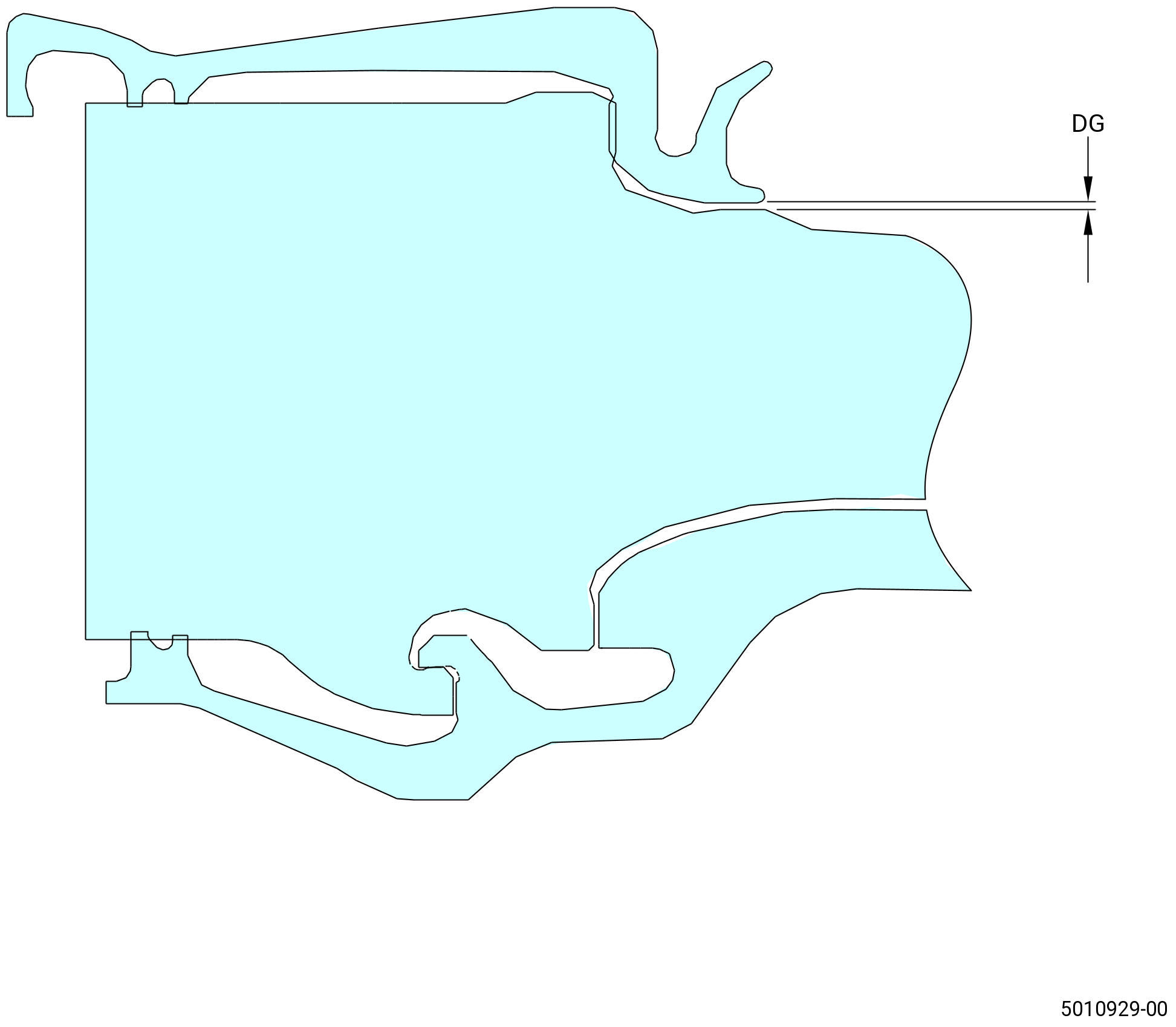
| (11) | Measure the gap between stage 1 blade retainer and stage 1 disk as follows: |
| (a) | Use C05-003 marking pen to mark 8 locations around the stage 1 disk at 45 degrees apart. |
| (b) | Measure the gap on dimension DG with a shim. Refer to Figure 1013. |
| (c) | Make sure the dimension DG is lower than 0.005 inch (0.13 mm). |
| Subtask 72-53-00-440-447 |
| (12) | Install the disk bore protector (item 10) of the 11C3024 assembly/disassembly fixture. Refer to Figure 1005. |
| Subtask 72-53-00-220-230 |
| (13) | Do a general visual inspection of the exposed surfaces of HPT rotor stage 1 disk for nicks, dents, and scratches after the removal of tooling. Refer to TASK 72-00-53-200-802 (72-00-53, INSPECTION 001 - CONFIG 02). Refer to Figure 1011. |
| Subtask 72-53-00-440-448 |
| J. | Lubricate the interstage seal (02-170) (SIN 150B3) and the stage 1 disk (02-280) (SIN 150A1) as follows: |
| WARNING: |
|
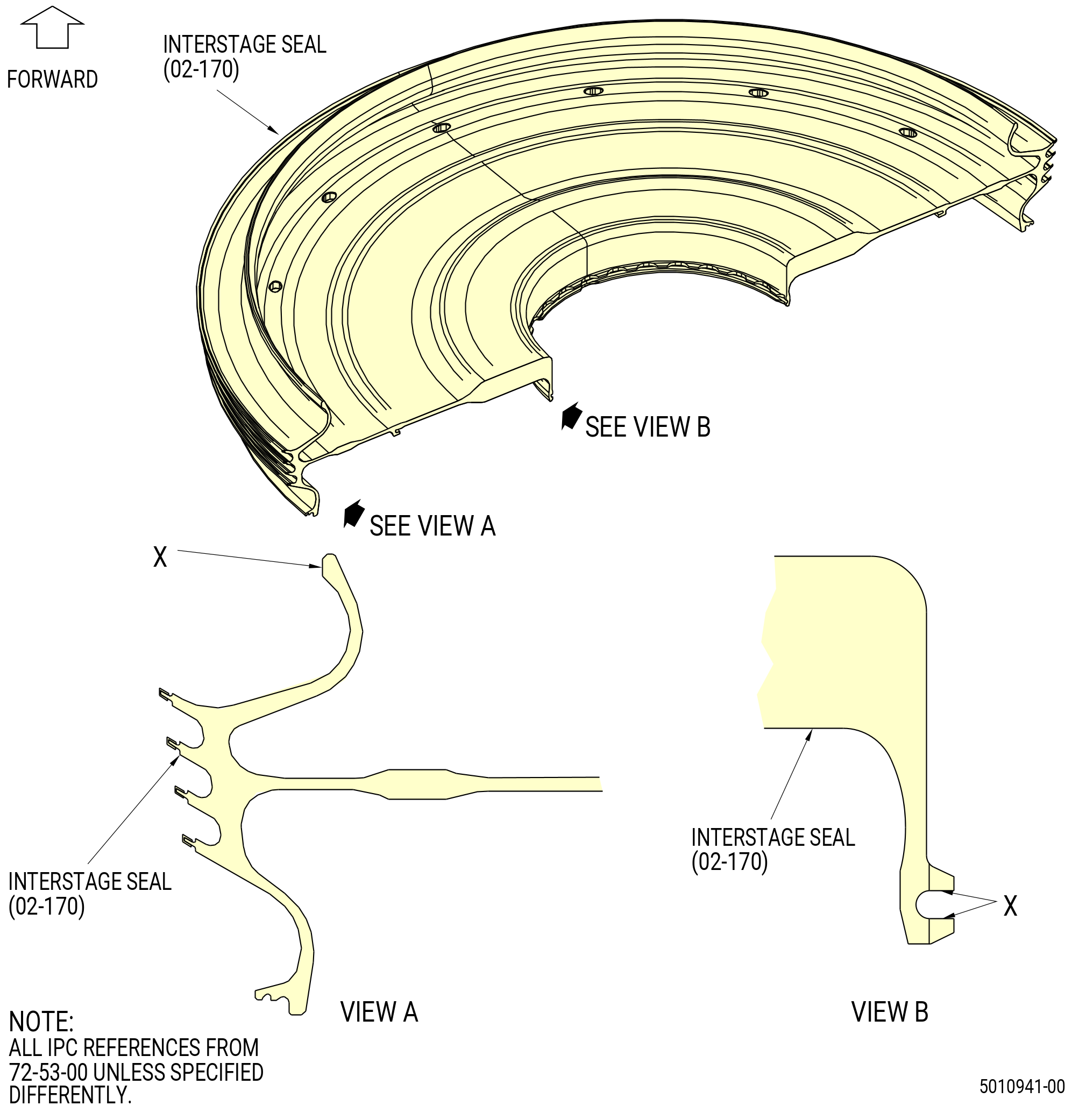
| (1) | Apply C02-033 lubricant to the surfaces of the interstage seal that will touch the stage 1 disk (02-280) (SIN 150A1). Refer to the areas labeled X in Figure 1014. |
| (2) | Turn the interstage seal and put it, aft end up, on a work table. |
| WARNING: |
|
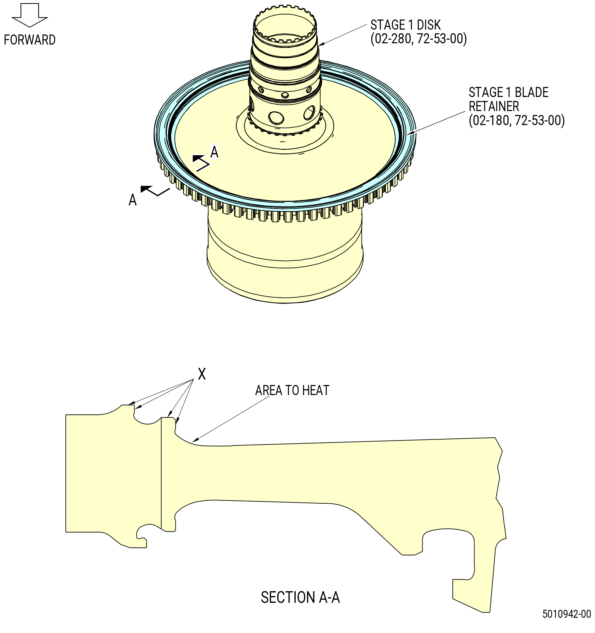
| (3) | Apply C02-033 lubricant to the surfaces of the stage 1 disk that will touch the interstage seal. Refer to the areas labeled X in Figure 1015. |
| (4) | Remove the disk bore protector (item 10) of the 11C3024 assembly/disassembly fixture from the aft end of the stage 1 disk shaft. Refer to Figure 1005. |
| Subtask 72-53-00-440-449 |
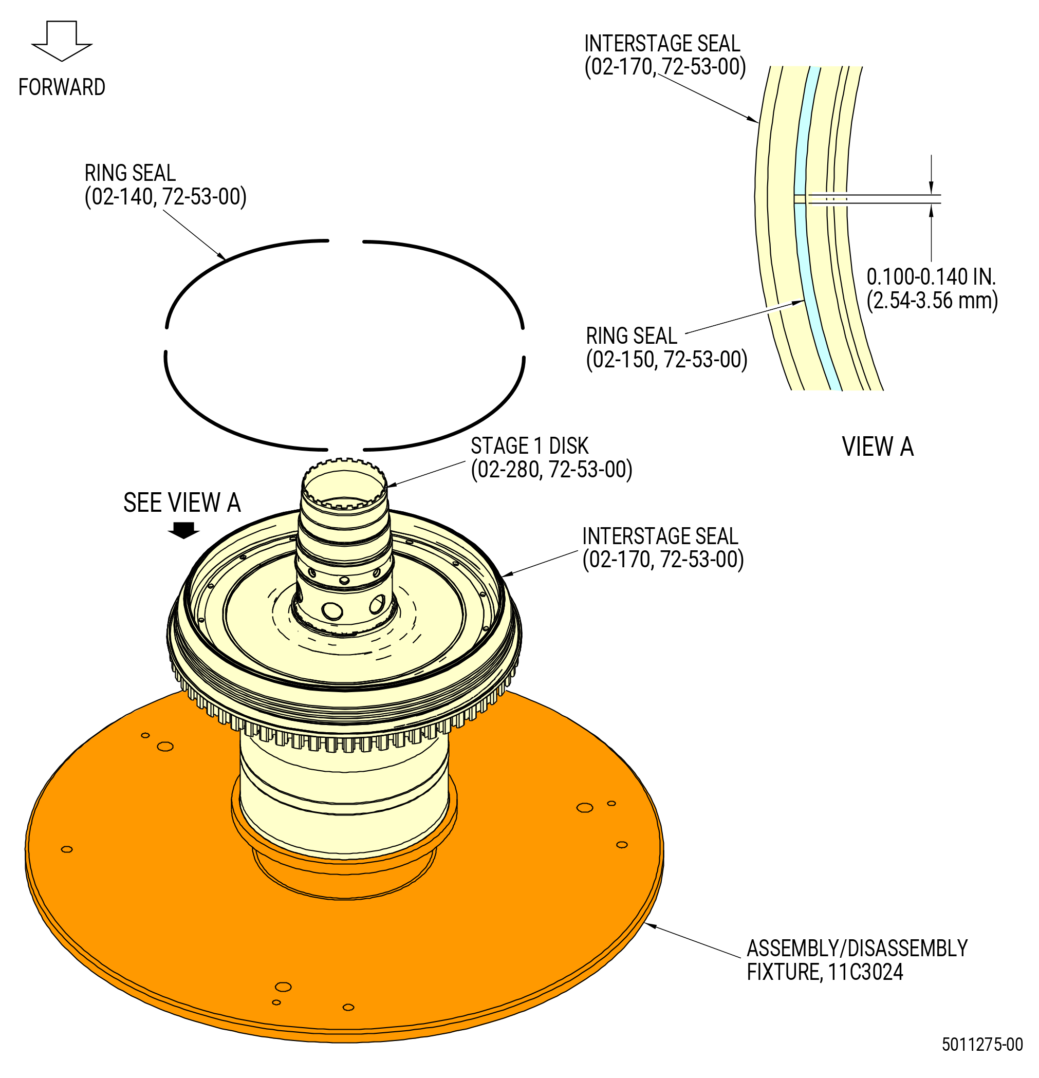
| K. | Install the ring seal (02-140) (SIN 150N3) in the interstage seal (02-170) (SIN 150B3). Refer to Figure 1016 and do as follows: |
| (1) | Cut four ring seal segments to 20.00 inches (508.0 mm) in length. |
| (2) | Use a file to remove unwanted material from the ends of the ring seal segments and make the ends square. Make sure that there are no burrs on the segments. |
| (3) | Put the ring seal segments into the groove in the aft face of the interstage seal (02-170) (SIN 150B3). Apply C10-012 tape to hold it in position, then install the next segment. Keep an end gap of 0.100-0.140 inch (2.54-3.56 mm). |
| (4) | Repeat this procedure until all of the ring seal (02-140) (SIN 150N3) segments are installed. Cut the segments as necessary to keep an end gap of 0.100- 0.140 inch (2.54-3.56 mm). |
| (5) | Measure the distances between the ends of the ring seal (02-140) (SIN 150N3) segments as follows: |
| (a) | If the distance is more than 0.140 inch (3.56 mm), install a new ring seal segment. |
| (b) | Remove a part of the ring seal (02-140) (SIN 150N3) segment if the distance is less than 0.100 inch (2.54 mm). |
| (6) | Remove the C10-012 tape and the ring seal (02-140) (SIN 150N3) from the interstage seal (02-170) (SIN 150B3). |
| WARNING: |
|
| (7) | Apply small amounts of C01-027 synthetic adhesive or C01-037 synthetic adhesive in the groove in the forward face of the interstage seal and on each of the ring seal segments. |
| (8) | Install the ring seal in the groove in the aft face of the interstage seal (02-170) (SIN 150B3). |
| (9) | Let the C01-027 synthetic adhesive or C01-037 synthetic adhesive to cure for 15-20 minutes or until it is tacky. |
| NOTE: |
|
| (10) | Make sure that the ring seal segments are fully in the groove of the interstage seal (02-170) (SIN 150B3) and does not go above the groove of the interstage seal (02-170) (SIN 150B3). |
| (11) | Measure the distances between the ends of the ring seal segments to make sure that they are 0.100-0.140 inch (2.54-3.56 mm). |
| Subtask 72-53-00-440-450 |
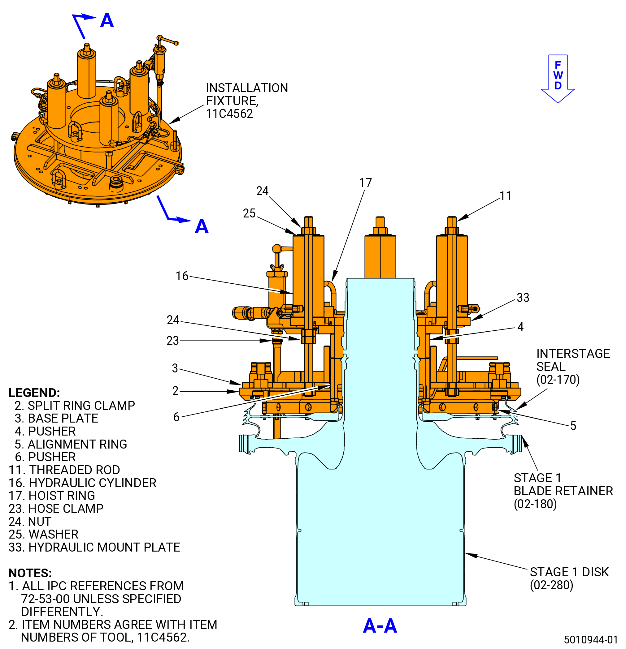
| L. | Install the 11C4562 installation fixture on the interstage seal (02-170) (SIN 150B3). Refer to Figure 1017 and do as follows. |
| (1) | Install the pusher lower tube (item 6). Use the four pins into the two slots of the center hub of the interstage seal. |
| (2) | Install the alignment ring (item 5).The four tube pusher pins must be oriented at 11 o’clock to 5 o’clock position. |
| (3) | Install the split ring clamp (item 2). Make sure the numbers 1/1 and 2/2 are oriented as shown in Figure 1017. |
| (4) | Install the two split ring bolt snug at each side of the split ring clamp (item 2). |
| (5) | Lift the base plate (item 3) and install it on the split ring clamp (item 2). Refer to Figure 1017. |
| (6) | Attach the base plate (item 3) with 12 bolts and 12 washers. |
| (7) | Install the pusher upper tube (item 4) on the pusher lower tube (item 6). |
| (8) | Lift the hydraulic mount plate (item 33) and install it on the pusher upper tube (item 4). |
| (9) | Make sure to align the four pins on the bottom of the hydraulic mount plate (item 33) with the four holes on the pusher upper tube (item 4). |
| (10) | Install four washers (item 25) and four nuts (item 24). |
| (11) | Measure deflection gap it must be 0.265-0.275 inch 0.265-0.275 inch (6.73-6.98 mm). |
| (12) | If deflection gap is out of the limits adjust to 0.265-0.275 inch (6.73-6.98 mm). |
| Subtask 72-53-00-440-451 |
| M. | Increase the temperature of the stage 1 disk (02-280) (SIN 150A1) and the blade retainer (02-180) (SIN 150BB). Refer to Figure 1018 and do as follows: |
| (1) | Use the 11C3021 heater fixture and the 11C4626 insulation blanket to apply heat to the stage 1 disk. |
| WARNING: |
|
| CAUTION: |
|
| (2) | coverstage 1 disk and blade retainer with heat blanket as shown in Figure 1018. |
| (3) | Apply heat until the temperature of the stage 1 disk rabbet and retainer is 500°F (260°C). |
| (4) | Measure the temperature with a calibrated temperature probe. Make sure that the temperature is not more than 700°F (371°C) as maximum. |
| Subtask 72-53-00-440-452 |
| CAUTION: |
|
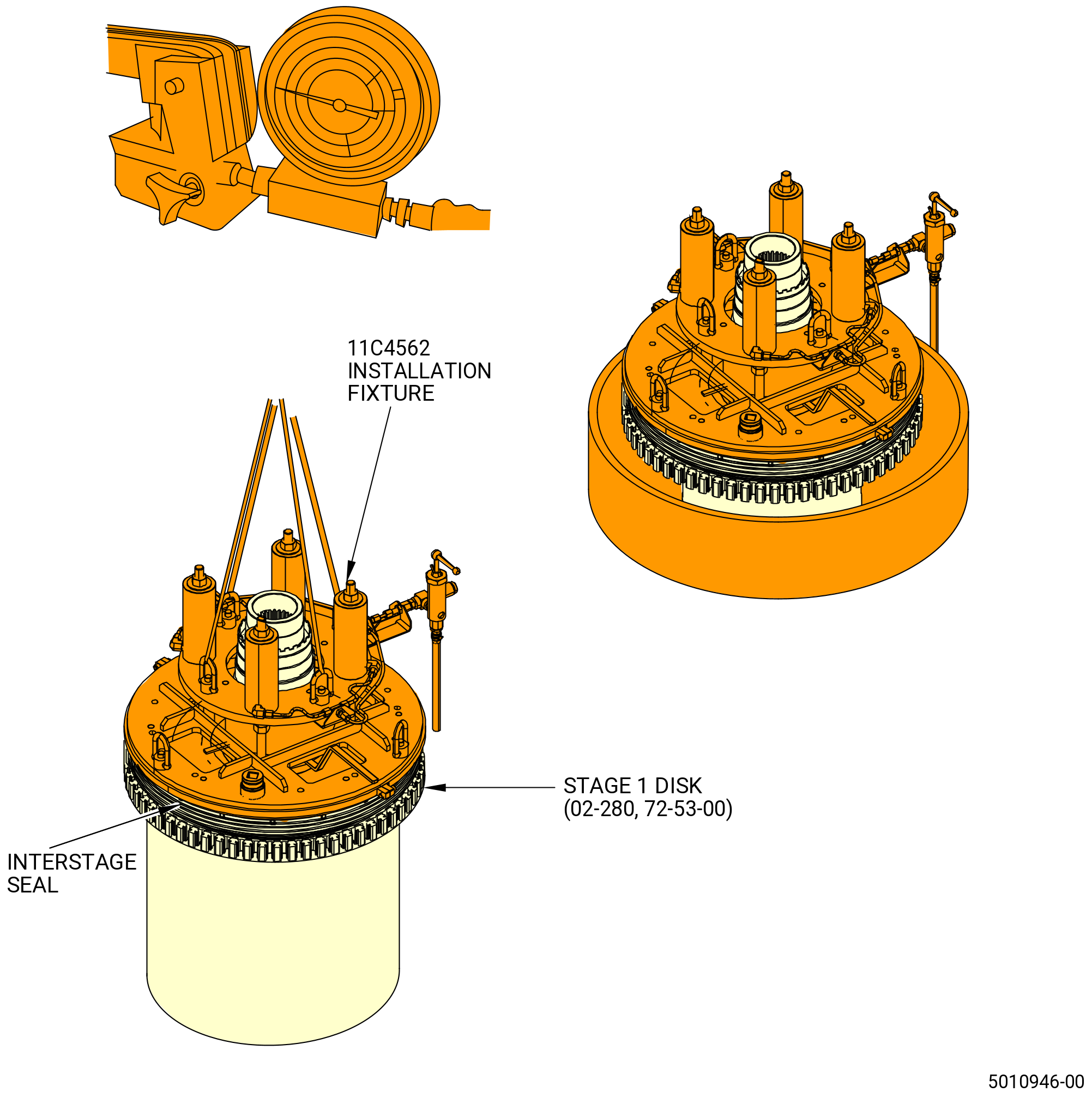
| N. | Install interstage seal to the stage 1 disk. Refer to Figure 1020 and do as follows: |
| (1) | Connect the neumatic pressure hose (ENERPAC) to the hydraulic coupler assembly (item 15) of the 11C4562 installation fixture. |
| (2) | Increase the pressure to 1500 PSI (10342 KPA) on the gage. |
| (3) | Attach four leg cable sling to the ring hoist (item 17) of the 11C4562 installation fixture. |
| WARNING: |
|
| WARNING: |
|
| (4) | Lift the interstage seal with a hoist and put it on 7C2141 dam chill fixture with liquid nitrogen for 10 minutes. Refer to Figure 1020. |
| (5) | Install interstage seal on the stage 1 disk as follows: |
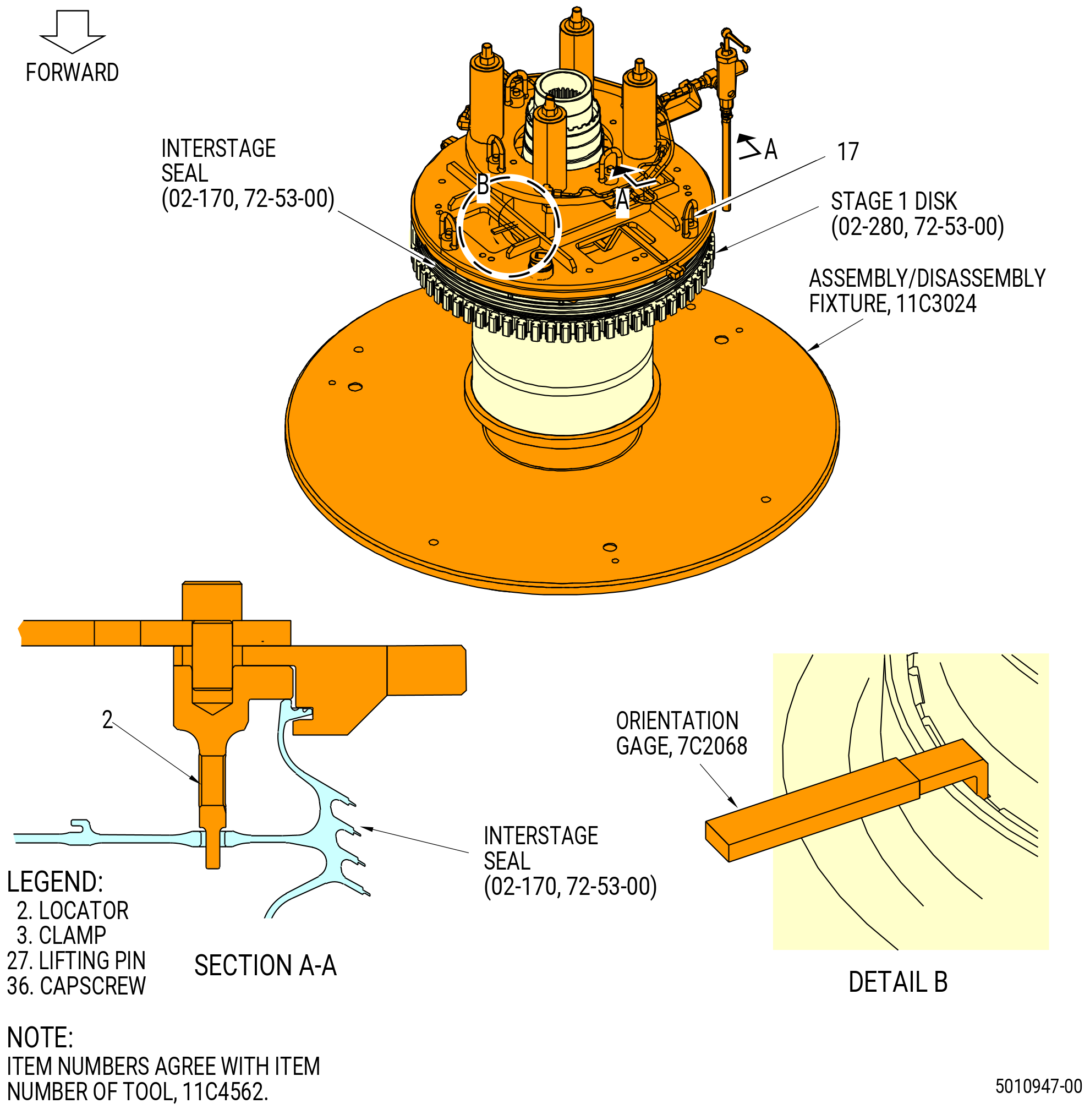
| (a) | Align the bayonets of the inner hub with stage 1 disk shaft. |
| (b) | Rotate the interstage seal to allow the lock key slots accept the 7C2068 orientation gage. |
| (6) | Verify lock key slot alignment with 7C2068 orientation gage. |
| (7) | Release the hydraulic pressure on the ENERPAC to let the forward rabbet to engage. |
| (8) | Remove tool 11C4562 installation fixture. |
| (9) | Remove the disk bore protector (item 10) of the 11C3024 assembly/disassembly fixture from the end of the shaft base (item 5). |
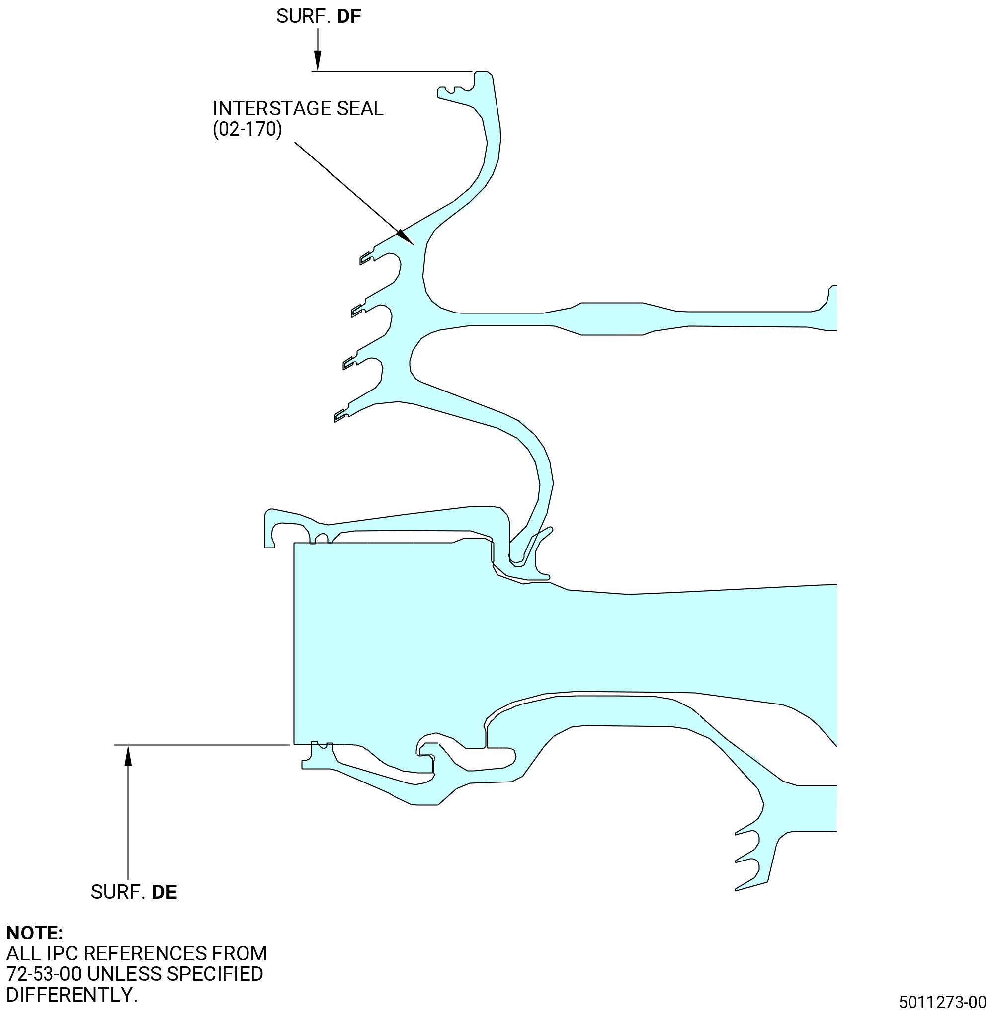
| (10) | After installation of the interstage seal and removal of the tooling, do a drop check from surface DE to surface DF. Measure at a minimum of 8 equally spaced locations around the circumference with the maximum variation not to exceed 0.010 inches (0.251 mm). Refer to Figure 1021. |
| Subtask 72-53-00-220-231 |
| (11) | Do a general visual inspection of the exposed surfaces of HPT rotor stage 1 disk for nicks, dents, and scratches after the removal of tooling. Refer to TASK 72-00-53-200-802 (72-00-53, INSPECTION 001 - CONFIG 02). Refer to Figure 1019. |
| Subtask 72-53-00-220-189 |
| O. | Do a visual inspection of the ring seal (02-140) (SIN 150N3). Refer to Figure 1023. |
| (1) | Make sure that the ring seal segments (02-140) (SIN 150N3) are in the correct groove on the interstage seal (02-170) (SIN 150B3). |
| Subtask 72-53-00-440-453 |
| (2) | If the ring seal segments (02-140) (SIN 150N3) are not correctly installed in the groove, remove and install the ring seal segments (02-140) (SIN 150N3) again. Refer to Subtask 72-53-00-440-449 (paragraph 3.K.). |
| Subtask 72-53-00-440-454 |
| CAUTION: |
|
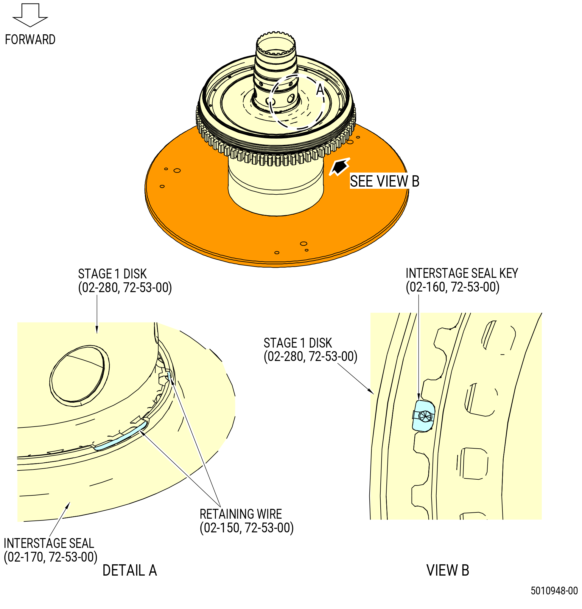
| P. | Install the HPT rotor interstage seal keys (interstage seal keys) (02-160) (SIN 150AE) in the four spaces in the interstage seal (02-170) (SIN 150B3) between the tabs of the stage 1 disk (02-280) (SIN 150A1). Refer to Figure 1024. |
| Subtask 72-53-00-440-455 |
| CAUTION: |
|
| Q. | Install the interstage seal key retaining wire (retaining wire) (02-150) (SIN 150W8) into the groove around the interstage seal (02-170) (SIN 150AE) as follows: |
| WARNING: |
|
| WARNING: |
|
| (1) | Retaining wire can be chilled with dry ice or liquid nitrogen prior to installation |
| WARNING: |
|
| (2) | Apply C02-033 lubricant on the retaining wire. |
| (3) | Put the straight end in first. |
| (4) | Push the retaining wire along the groove and under the interstage seal keys (02-160) (SIN 150AE) so that the shape is not changed. |
| (5) | After the installation of the retaining wire, make sure that the hook end of the retaining wire points to the inner diameter. |
| Subtask 72-53-00-220-232 |
| (6) | Do a general visual inspection of the exposed surfaces of HPT rotor stage 1 disk for nicks, dents, and scratches after the removal of tooling. Refer to TASK 72-00-53-200-802 (72-00-53, INSPECTION 001 - CONFIG 02). Refer to Figure 1025. |
| Subtask 72-53-00-440-456 |
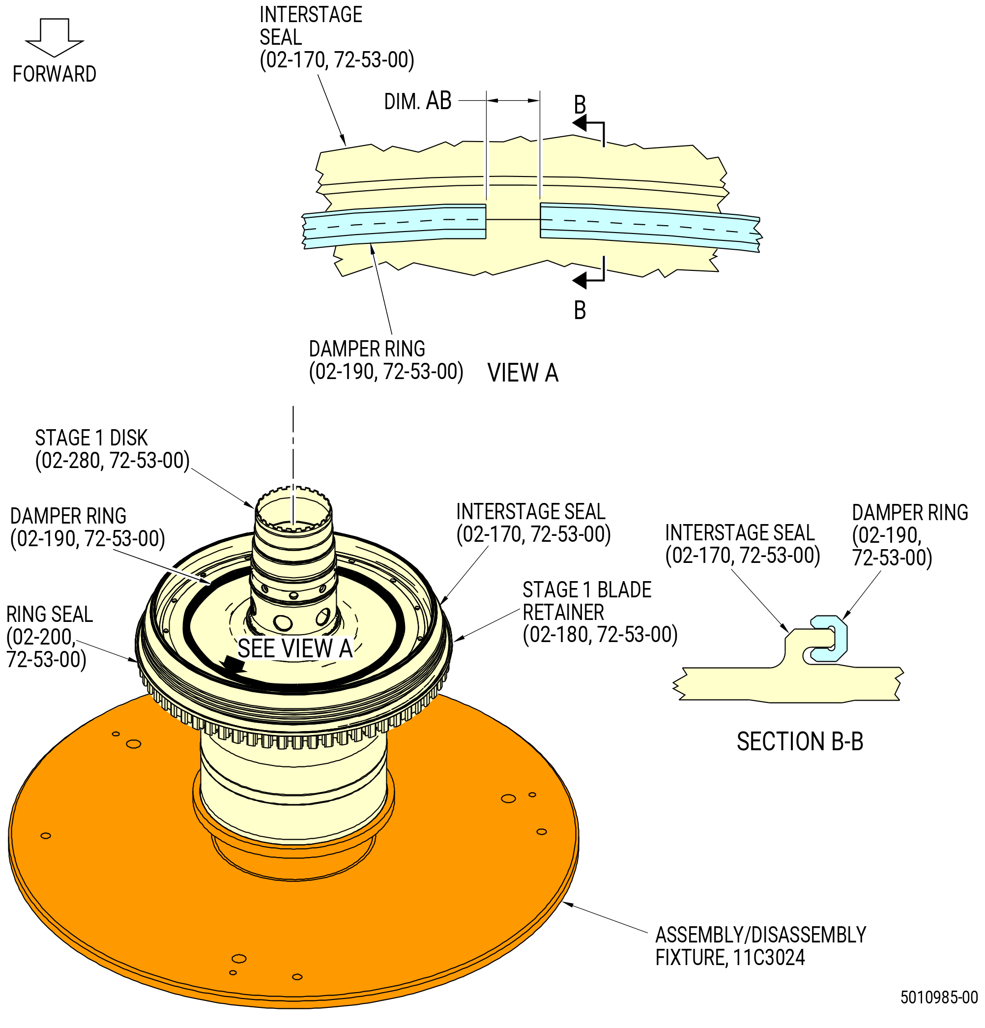
| R. | Install the damper ring (02-190) (SIN 150B9) on the interstage seal (02-170) (SIN 150B3). Refer to Figure 1026 and do as follows: |
| (1) | Compress the damper ring and install it in position on the aft side of the interstage seal. |
| Subtask 72-53-00-220-190 |
| (2) | Measure dimension AB between the ends of the damper ring as follows: |
| (a) | Make sure that the damper ring is fully in position. |
| (b) | Measure dimension AB with a vernier caliper. Make sure that the distance is a minimum of 0.060 inch (1.52 mm). |
| Subtask 72-53-00-440-457 |
| CAUTION: |
|
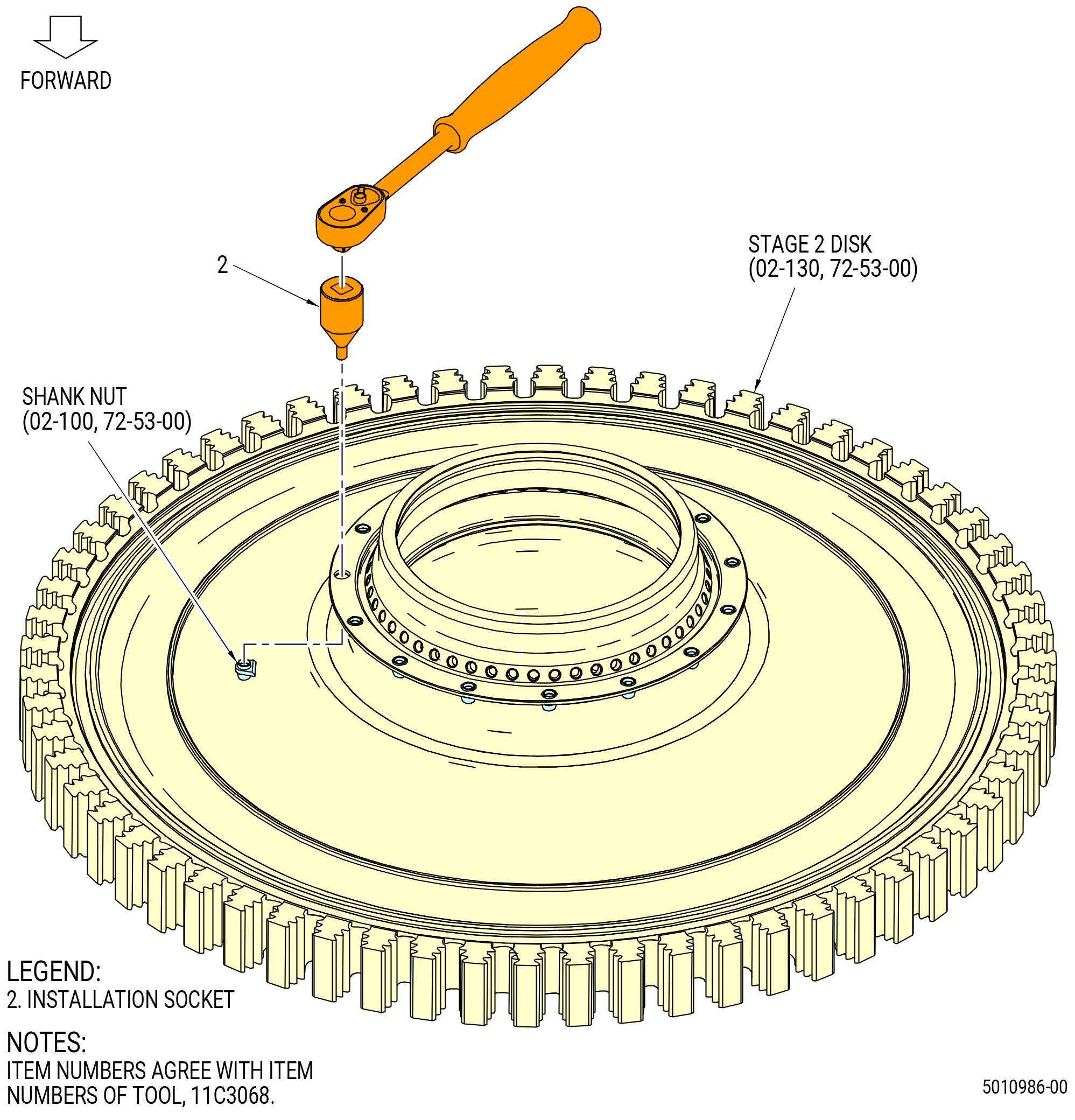
| S. | Alternative Procedure Available. Assemble the self-locking shank nuts (shank nuts) (02-100) (SIN 15041) into the aft flange of the HPT rotor stage 2 disk (stage 2 disk) (02-130) (SIN 150B1) with the 11C3068 install/remove fixture. Refer to Figure 1027 and do as follows: |
| (1) | Install the shank nuts (02-100) (SIN 15041) into the aft flange of the stage 2 disk. |
| (2) | Put the installation socket (item 2) on a 3/8-inch ratchet. |
| (3) | Put the installation socket (item 2) into the front flange of the stage 2 disk and turn it CW into the shank nut (02-100) (SIN 15041). |
| (4) | Continue to turn the ratchet CW until the shank nut (02-100) (SIN 15041) is tight against the stage 2 disk. |
| (5) | Repeat steps 1 through 4 for each shank nut (02-100) (SIN 15041). |
| Subtask 72-53-00-220-191 |
| (6) | Make sure that there are no cracks in the shank nuts. |
| Subtask 72-53-00-220-192 |
| (7) | Make sure that the washer faces of the shank nuts are fully flush with the flange of the stage 2 disk. |
| (8) | Do a general visual inspection of the exposed surfaces of HPT rotor stage 2 disk for nicks, dents, and scratches after the removal of tooling. Refer to TASK 72-00-53-200-802 (72-00-53, INSPECTION 001 - CONFIG 02). Refer to Figure 1028. |
| Subtask 72-53-00-440-458 |
| CAUTION: |
|
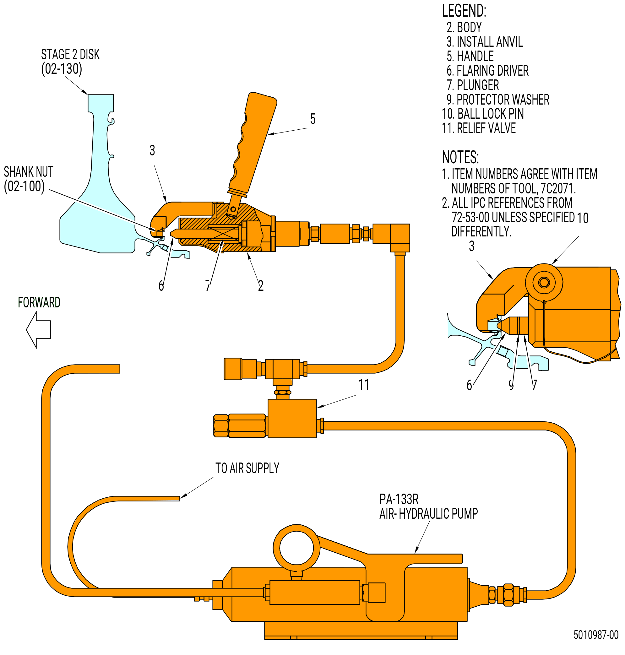
| S.A. | Alternative Procedure. Install the shank nuts (02-100) (SIN 15041) in the aft flange of the stage 2 disk (02-130) (SIN 150B1) with the 7C2071 install/remove fixture. Refer to Figure 1030 and do as follows: |
| (1) | Install the shank nuts (02-100) (SIN 15041) in the HPT rotor stage 2 disk (02-130) (SIN 150B1) flange with the 7C2071 install/remove fixture. Refer to Figure 1030 and do as follows: |
| (a) | Remove the protection from the 7C2071 install/remove fixture. |
| (b) | Wipe clean the 7C2071 install/remove fixture parts and HPT rotor stage 2 disk (02-130) (SIN 150B1) with C10-182 lint free cloth. |
| (c) | Examine the 7C2071 install/remove fixture for damage and foreign material and high metal. |
| WARNING: |
|
| (d) | Clean mating surfaces with C04-035 isopropyl alcohol. |
| (e) | Install the flaring driver (item 6) on the plunger (item 7) of the 7C2071 install/remove fixture. |
| (f) | Install the install anvil (item 3) on the body (item 2) of the 7C2071 install/remove fixture with the ball lock pin (item 10). |
| (g) | Connect the PA-133R air hydraulic pump to the 7C2071 install/remove fixture relief valve (item 11) and a supply of clean, dry air. |
| (h) | Put the 12 shank nuts (02-100) (SIN 15041) in the flange holes in the HPT rotor stage 2 disk (02-130) (SIN 150B1) aft flange. |
| CAUTION: |
|
| (i) | Put the install anvil (item 3) of the 7C2071 install/remove fixture on a shank nut (02-100) (SIN 15041) and operate the 7C2071 install/remove fixture to extend the flaring driver (item 6) to install the shank nut (02-100) (SIN 15041). Do not apply more than 3600 psi (24821.1 kPa) to the fixture. |
| (j) | Move the 7C2071 install/remove fixture to the shank nuts (02-100) (SIN 15041) that remain and install them one at a time. |
| (k) | Make sure each shank nut (02-100) (SIN 15041) is tightly attached and the washer face of the shank nut (02-100) (SIN 15041) is flush with the flange. |
| (l) | When all of the shank nuts (02-100) (SIN 15041) are installed use a 3X magnification glass to do a visual inspection of all shank nuts (02-100) (SIN 15041) for cracks. No cracks are permitted. |
| (m) | Store the 7C2071 install/remove fixture. |
| Subtask 72-53-00-220-233 |
| (2) | Do a general visual inspection of the exposed surfaces of HPT rotor stage 2 disk for nicks, dents, and scratches after the removal of tooling. Refer to TASK 72-00-53-200-802 (72-00-53, INSPECTION 001 - CONFIG 02). Refer to Figure 1029. |
| Subtask 72-53-00-440-459 |
| CAUTION: |
|
| CAUTION: |
|
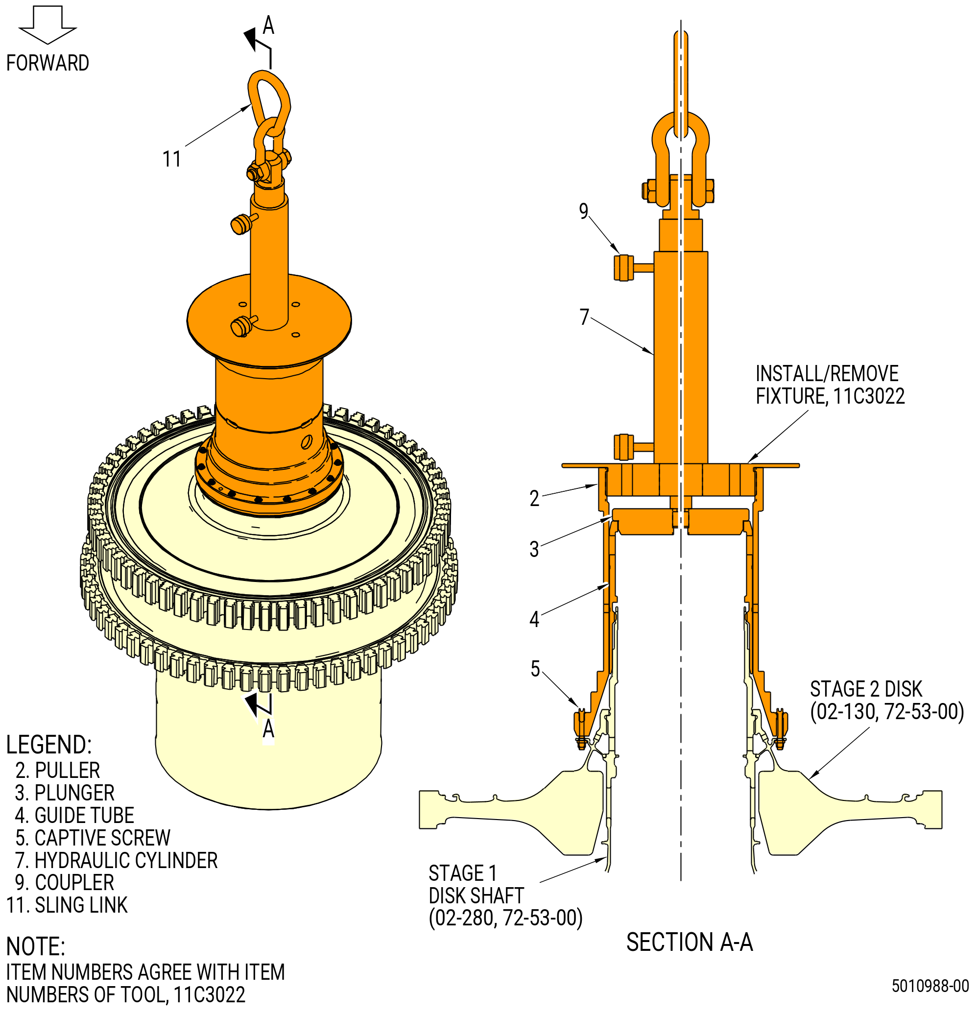
| T. | Assemble the stage 2 disk (02-130) (SIN 150B1) on the interstage seal (02-170) (SIN 150B3) and the stage 1 disk (02-280) (SIN 150A1) as follows: |
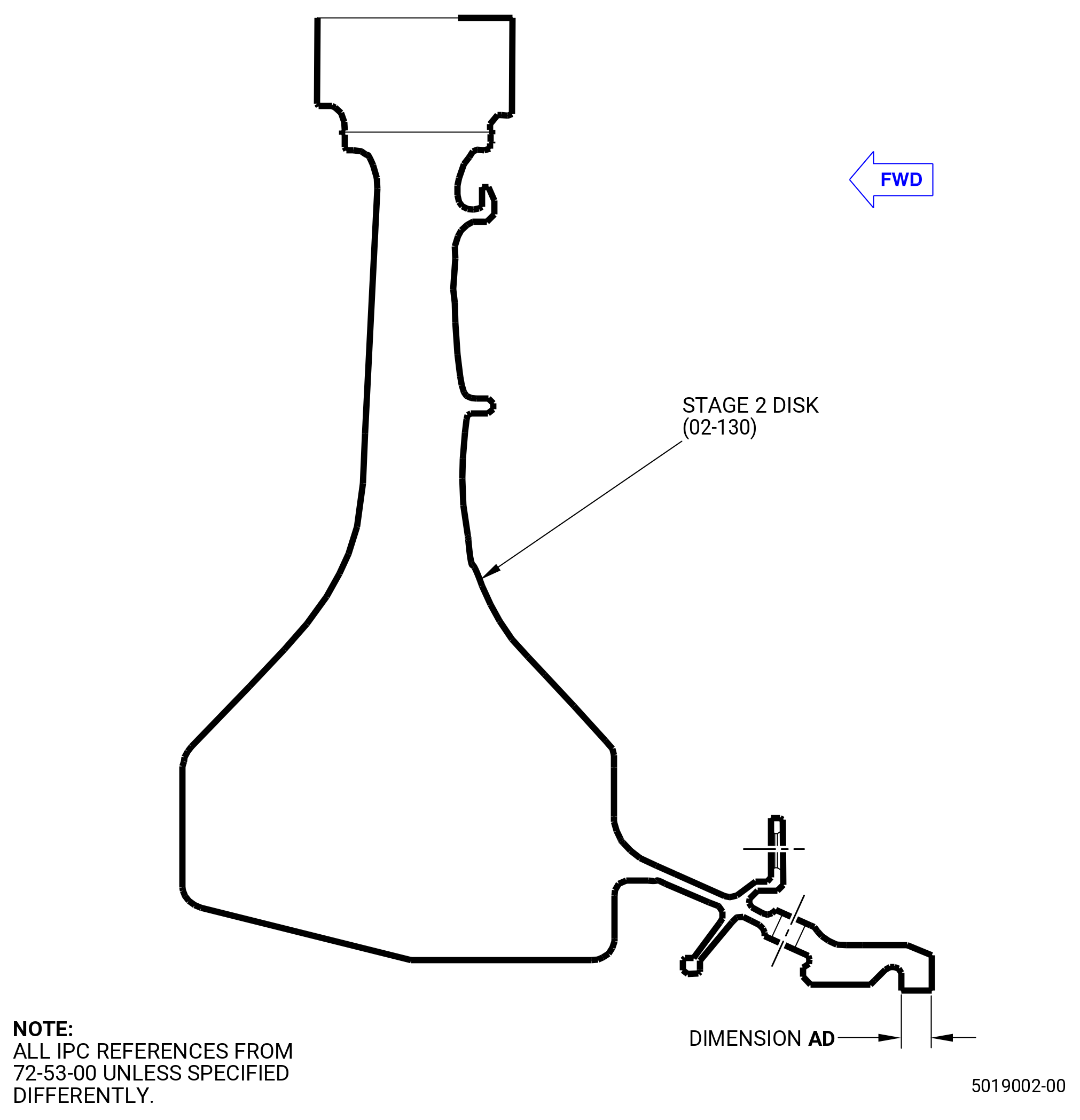
| (1) | Before the installation of the stage 2 disk (02-130) (SIN 150B1), measure the thickness of the aft shaft flange at four equally spaced locations. Record the average value as dimension AD. Refer to Figure 1031. |
| • |
|
| (2) | Before the installation of the stage 2 disk (02-130) (SIN 150B1), measure the stage 1 disk (02-280) (SIN 150A1) aft shaft axial drop from the aft castellations to the spline aft face at four equally spaced locations. Record the average value as dimension AE. Refer to Figure 1032. |
| • |
|
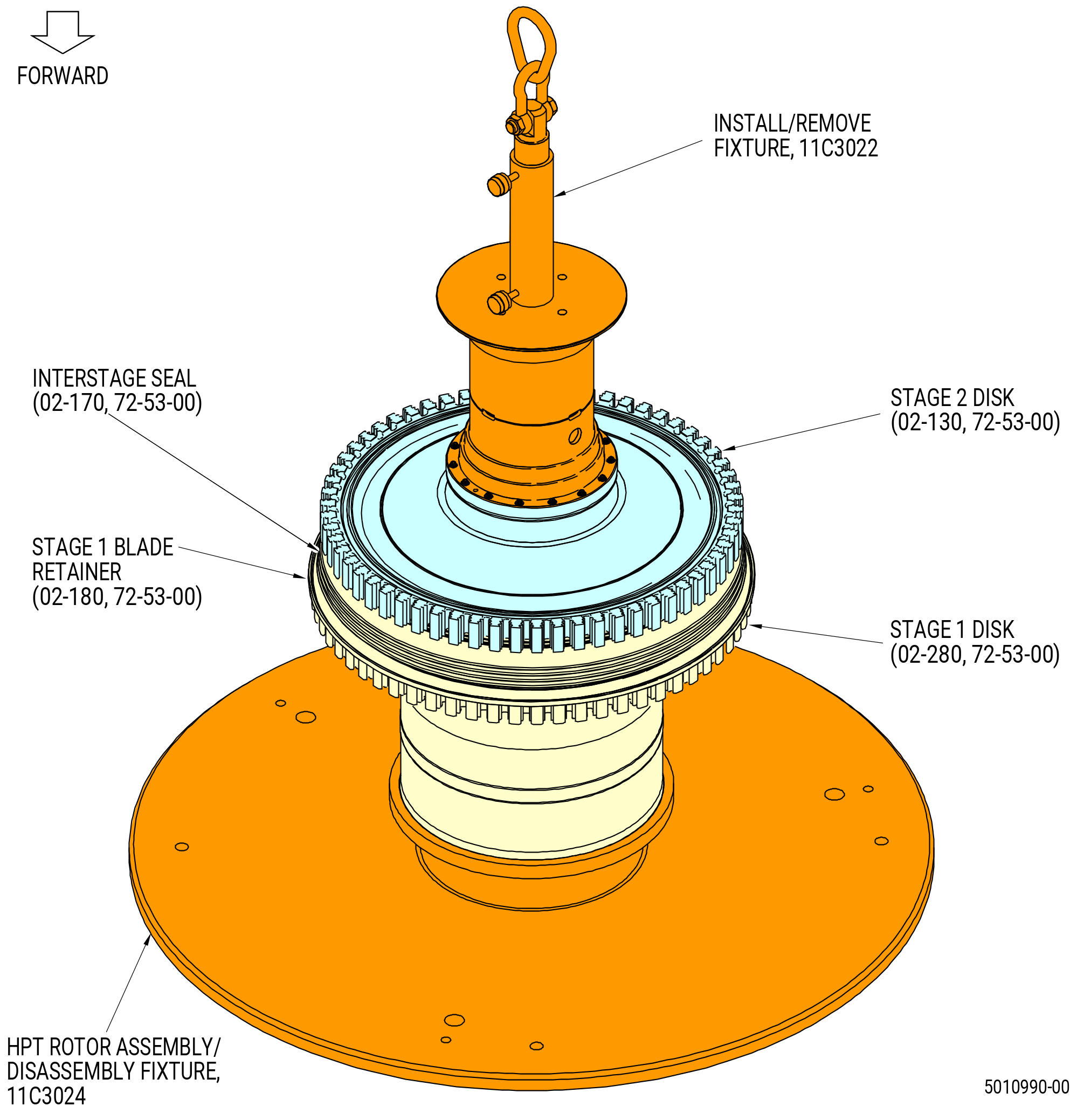
| (3) | Install the guide tube (item 4) of the 11C3022 install/remove fixture with the threads engaged on the aft end of the stage 1 disk shaft. Refer to Figure 1033. |
| (4) | Retract the hydraulic cylinder (item 7). |
| WARNING: |
|
| (5) | Attach a hoist to the sling link (item 11) to lift the puller (item 2). |
| (6) | Lower the puller (item 2) to the aft flange of the stage 2 disk (02-130) (SIN 150B1). |
| (7) | Attach the puller (item 2) to the aft flange of the stage 2 disk (02-130) (SIN 150B1) with the captive screws (item 5). Torque the captive screws (item 5) to 92-108 lb in. (10.4-12.2 N.m). |
| (8) | Use a C05-003 marking pen to mark in a CW direction ALF of the stage 2 disk (02-130) (SIN 150B1) the position of the 1-1 and 5-5 disk post. Refer to Figure 1034. |
| WARNING: |
|
| CAUTION: |
|
| NOTE: |
|
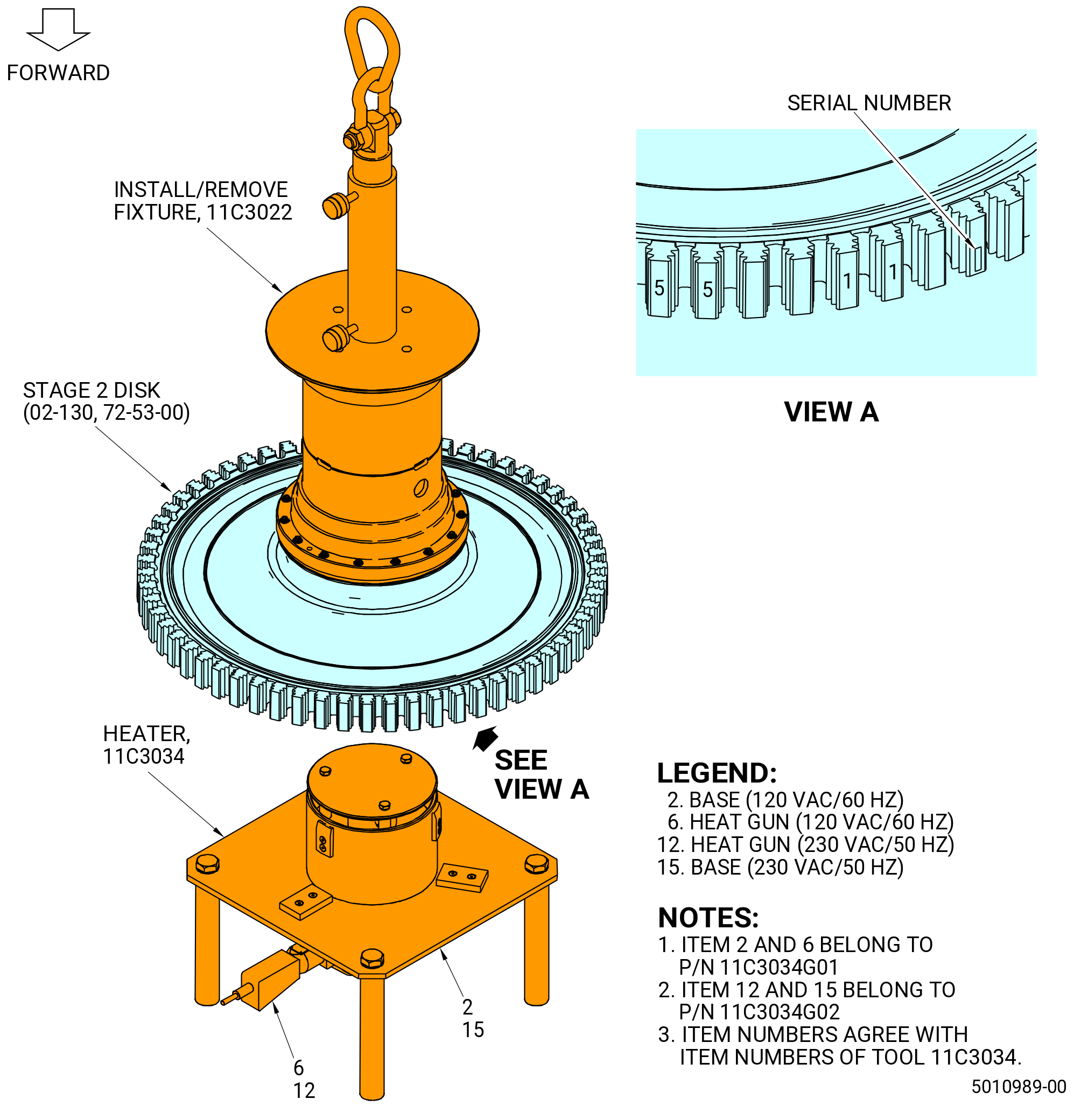
| (9) | Lift the stage 2 disk (02-130) (SIN 150B1) and put it on the 11C3034 heater (item 2 or item 15). |
| (10) | Increase the temperature of the stage 2 disk to 180 °F (82.2 °C). Refer to Figure 1034 and do as follows: |
| (a) | Plug in the heater (item 6 or item 12) into the electrical outlet and set the output to “high”. |
| (b) | Monitor the temperature of the stage 2 disk with a calibrated temperature probe. |
| (c) | When the disk temperature reaches 180 °F (82.2 °C) turn the heater to low. Allow the heater to operate in the low position for several minutes before turning off to accelerate the cooling of the heater. |
| (11) | Remove the bore disk protector (item 10) of the 11C3024 assembly/disassembly fixture. Refer to Figure 1005. |
| (12) | Remove the stage 2 disk (02-130) (SIN 150B1) from the 11C3024 heater and align the 1-1 slots of the stage 2 disk and stage 1 disk. Refer to Figure 1034. |
| (13) | Align the plunger (item 3) of the 11C3022 install/remove fixture with the aft end of the guide tube (item 4). Refer to Figure 1033. |
| (14) | Lower the stage 2 disk (02-130) (SIN 150B1) into position on the stage 1 disk/interstage seal assembly. Make sure that the 1-1 slots of the two disks are nearly/closely aligned. |
| Subtask 72-53-00-220-193 |
| (15) | Make sure that there is no space between the stage 2 disk and the interstage seal in a minimum of four positions. Use a 0.001 inch (0.03 mm) shim. |
| Subtask 72-53-00-440-460 |
| (16) | Remove the 11C3022 install/remove fixture. Refer to Figure 1035. |
| Subtask 72-53-00-220-234 |
| (17) | Do a general visual inspection of the exposed surfaces of HPT rotor stage 1 disk and stage 2 disk for nicks, dents, and scratches after the removal of tooling. Refer to TASK 72-00-53-200-802 (72-00-53, INSPECTION 001 - CONFIG 02). Refer to Figure 1036. |
| Subtask 72-53-00-440-461 |
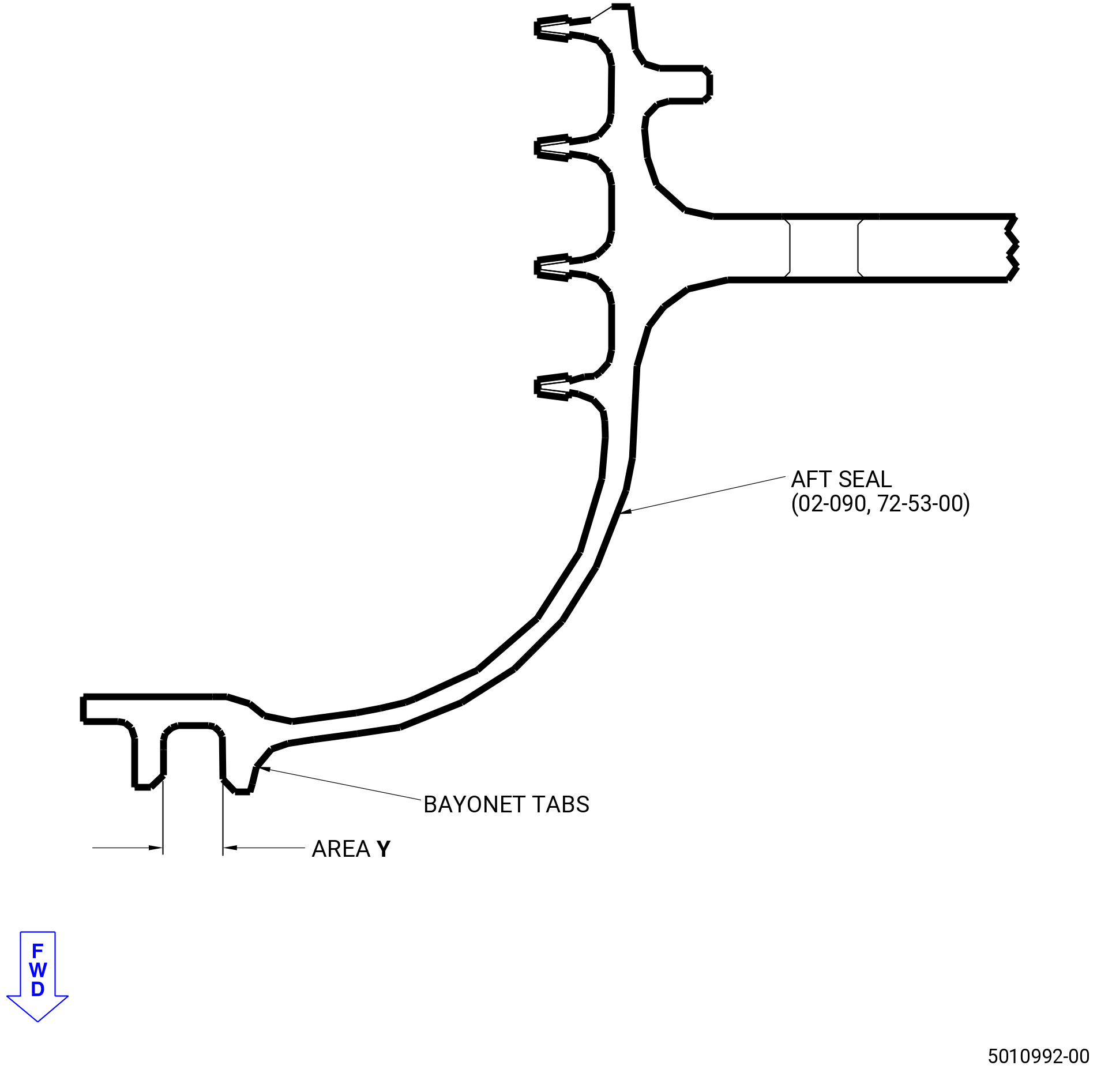
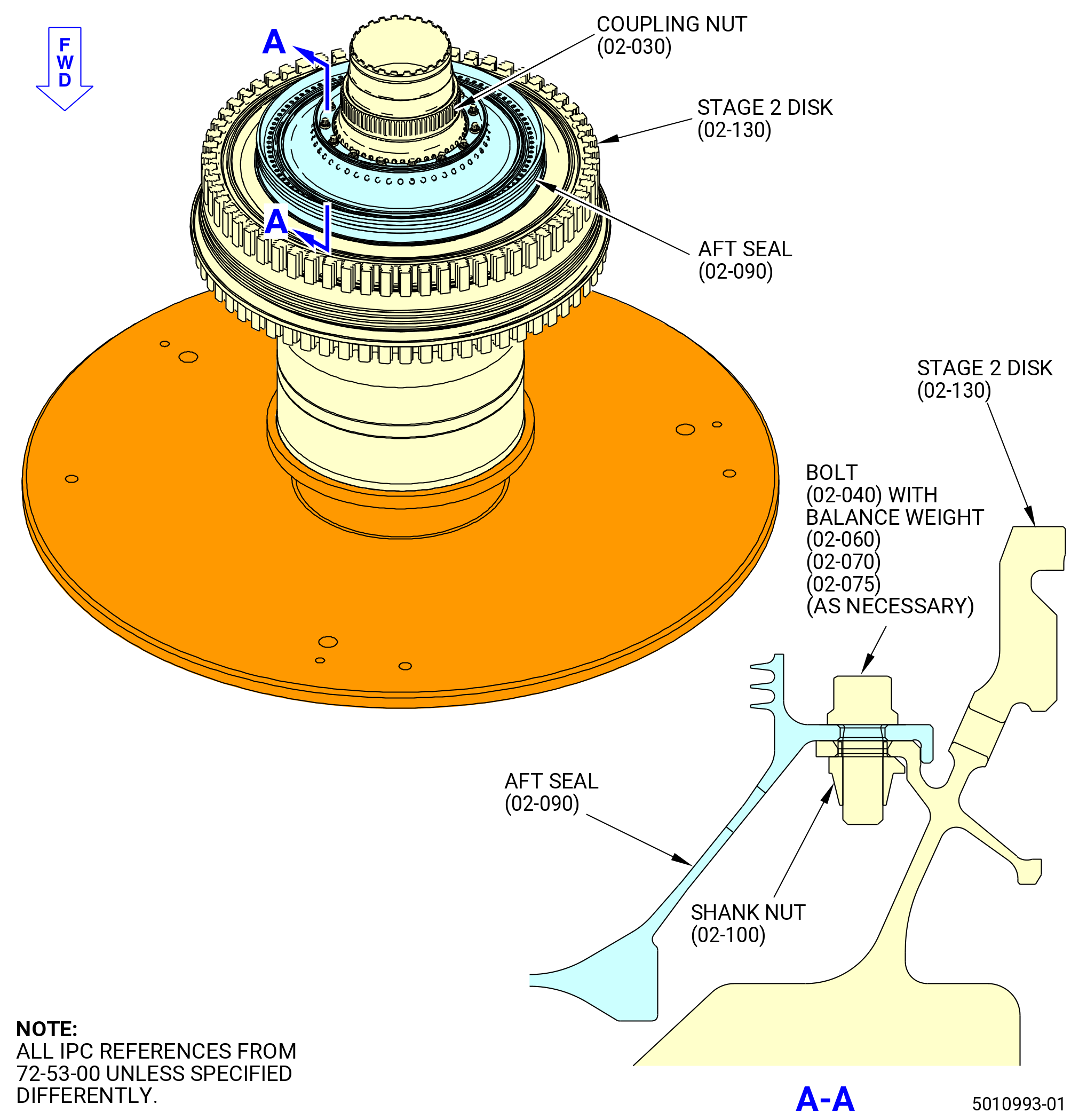
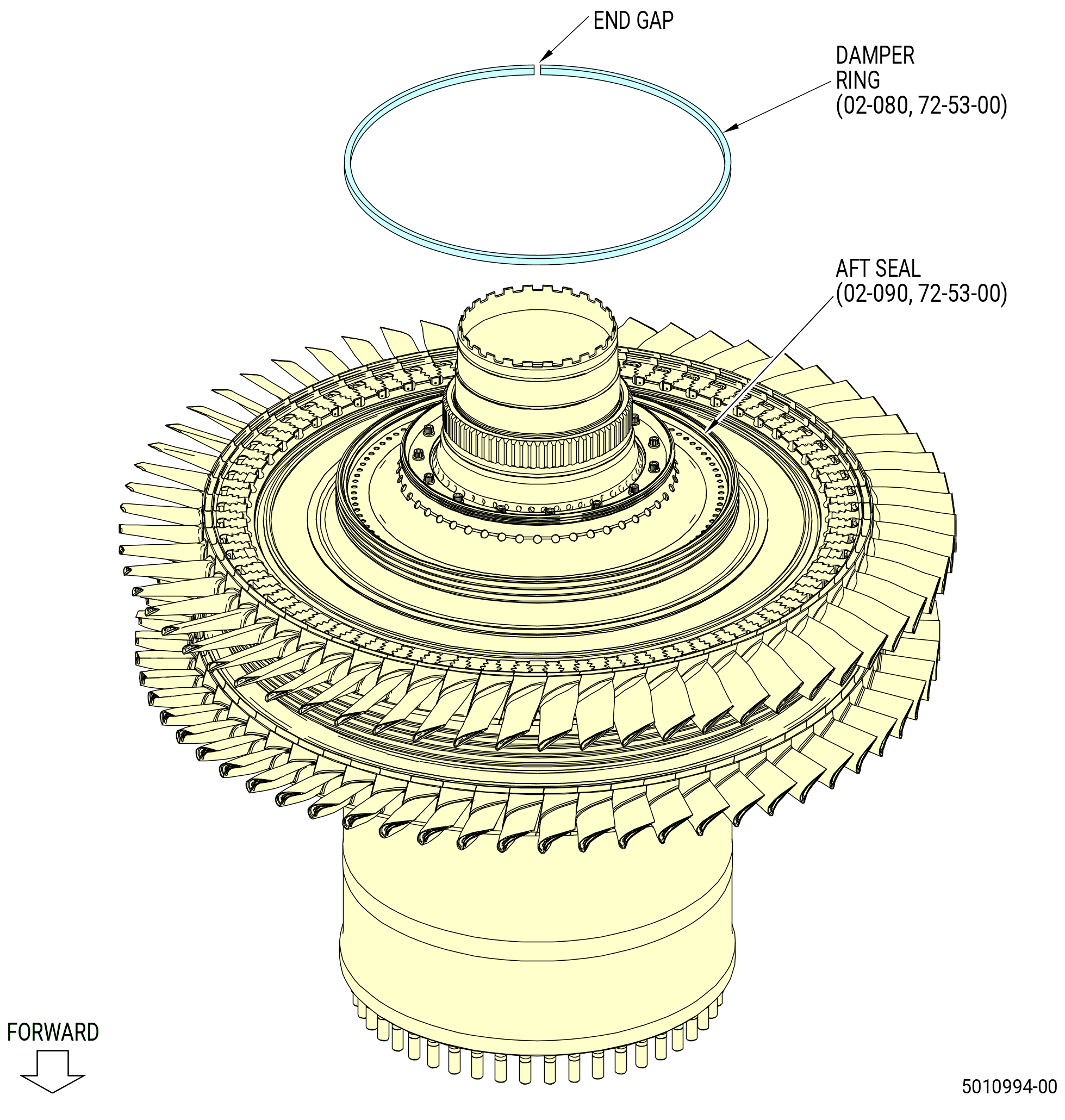
| U. | Assemble the HPT aft rotating seal (aft seal) (02-090) (SIN 150B4) to the stage 2 disk (02-130) (SIN 150B1) as follows: |
| (1) | Apply C02-033 lubricant to the surfaces of the bayonet on the forward side of the aft seal (02-090) (SIN 150B4) labeled Y. Refer to Figure 1038. |
| WARNING: |
|
| (2) | Fill a chill fixture with dry ice and chill the aft seal for 20-30 minutes. |
| (3) | Put the aft seal on the stage 2 disk. |
| (4) | Make sure that the bayonet tabs are aligned with the rail of the stage 2 disk and that the boltholes are aligned. |
| WARNING: |
|
| (5) | Apply C02-058 lubricant to the threads and friction surfaces of the machine bolts (bolts) (02-040) (SIN 15022). |
| NOTE: |
|
| NOTE: |
|
| (6) | Make sure the bayonet tab is fully seated on the rail of the stage 2 disk. |
| (7) | Install the bolts (02-040) (SIN 15022) through the aft seal and into the stage 2 disk. |
| (8) | Torque the bolts to 106-124 lb in. (12.0-14.0 N.m) in a criss-cross pattern. |
| (9) | Install the damper ring (02-080) (SIN 150BC) on the aft seal (02-090) (SIN 150B4). Refer to Figure 1040. |
| (10) | Measure the damper ring end gap. The end gap must be between 0.060-0.210 inch (1.52-5.33 mm). |
| Subtask 72-53-00-440-462 |
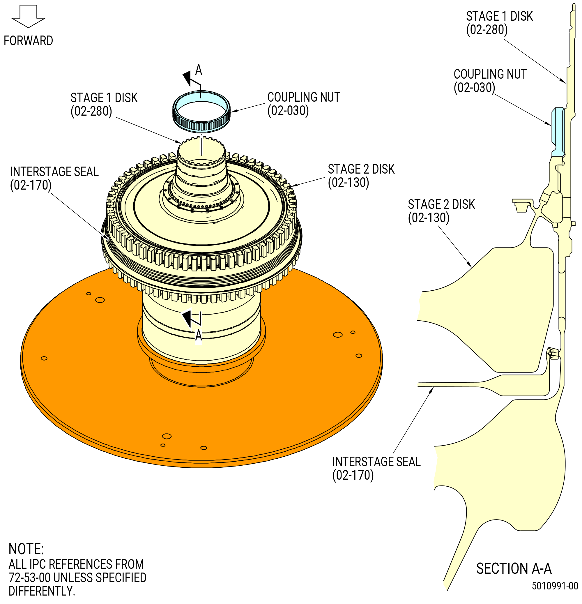
| V. | Torque the coupling nut (02-030) (SIN 150AD). Refer to TASK 72-53-00-800-801 (72-53-00, SPECIAL PROCEDURE 001). |
| Subtask 72-53-00-440-463 |
| W. | Deleted. |
| Subtask 72-53-00-220-194 |
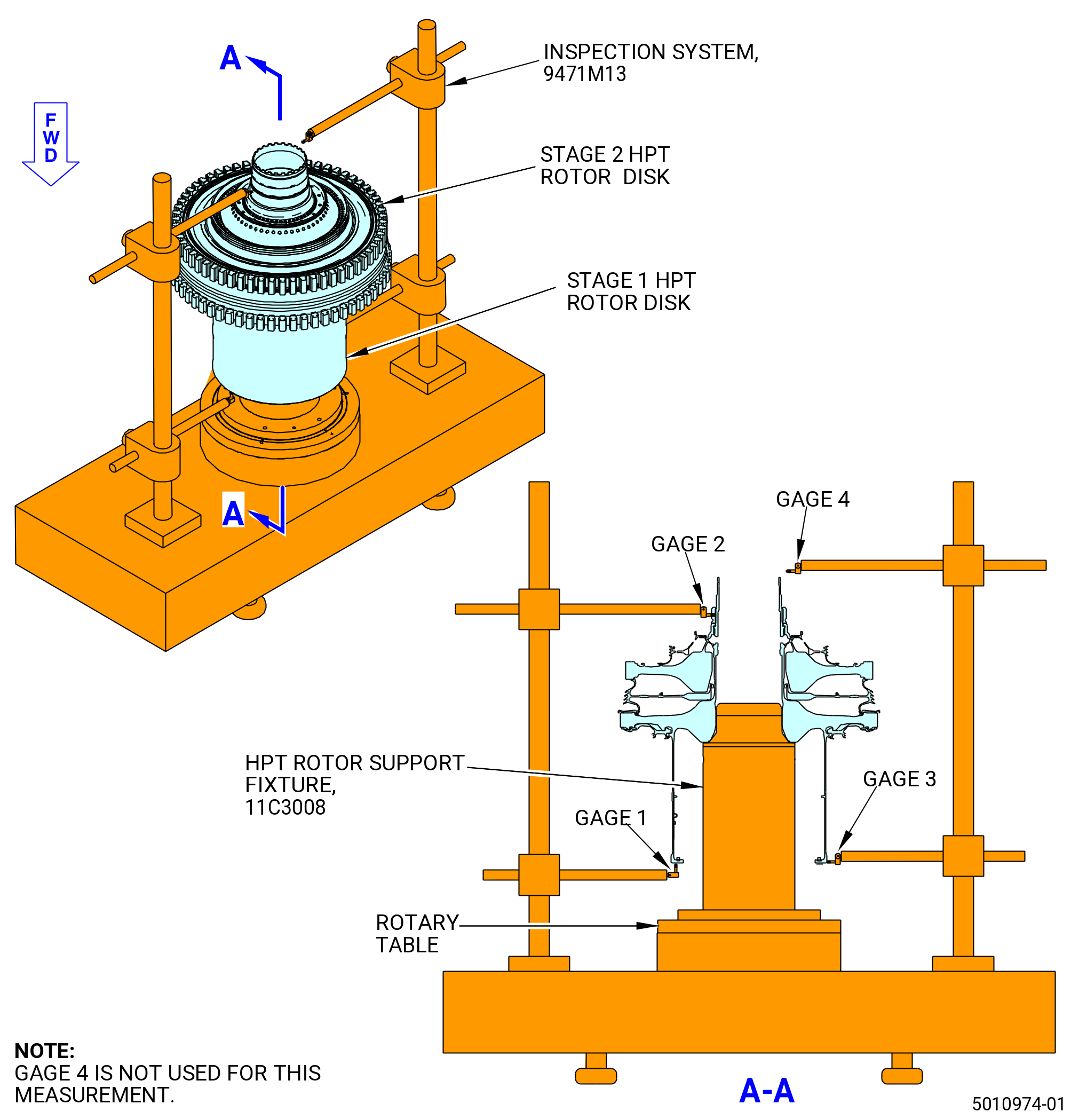
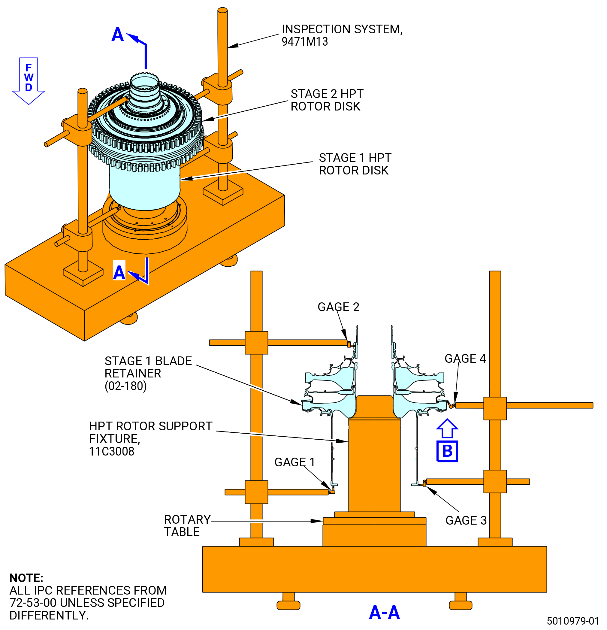
| X. | Do a runout measurement of the number 4 bearing journal: |
| (1) | If the 11C3008 HPT rotor support fixture is not installed on the rotary table of the 9471M13 inspection system, install it. Refer to Figure 1042 and do as follows: |
| WARNING: |
|
| (a) | Clean the top surface of the rotary table with C04-035 isopropyl alcohol. |
| WARNING: |
|
| (b) | Lift the 11C3008 HPT rotor support fixture and align the mounting holes with the holes in the rotary table of the 9471M13 inspection system. |
| (c) | Line up the 11C3008 HPT rotor support fixture mounting hole with the tapped holes in the rotary table and secure it with capscrews (item 7). Do not fully tighten the capscrews at this time. Refer to Figure 1002. |
| Subtask 72-53-00-220-195 |
| (a) | Make a selection of Tilt/Center from the main menu on the computer screen. |
| (b) | Make a selection of the setup named GEnx HPTR AFTER COUPLING NUT from the SELECT A PARAMETER FILE. |
| NOTE: |
|
| (c) | Put gage 1 against the O.D. of the 11C3008 HPT rotor support fixture base (item 2). |
| (d) | Push on the DISPLAY GAGES button on the computer screen. |
| (e) | Turn the rotary table and watch the readings. |
| (f) | Move the 11C3008 HPT rotor support fixture as necessary to center it on the rotary table within 0.004 inch (0.10 mm). |
| (g) | Tighten capscrews (item 7). |
| (h) | Remove gage 1 from the 11C3008 HPT rotor support fixture. |
| (2) | Do the runout of the number 4 bearing journal as follows: |
| (a) | Attach the 11C3056 lift fixture to the threads on the aft end of the stage 1 disk (02-280) (SIN 150A1). Turn CW, ALF, until the 11C3056 lift fixture is fully engaged on the HPT rotor shaft. Lower the HPT Rotor assembly (34-021 , 72-00-02) (SIN 15000) on to the 11C3008 HPT rotor support fixture. |
| (b) | Remove the 11C3056 lift fixture. |
| CAUTION: |
|
| NOTE: |
|
| (c) | Put the plunger of gage 1 against the forward rabbet of the front shaft outboard of the bolt holes. |
| (d) | Put the lever of gage 3 against the forward face of the front shaft directly across from gage 1. |
| (e) | Put the plunger of gage 2 against the number 4 bearing journal. |
| NOTE: |
|
| (f) | Push on the DISPLAY GAGES button on the computer screen. |
| (g) | Adjust all of the gages so the bar graphs are close to zero. |
| NOTE: |
|
| NOTE: |
|
| (h) | Push on the DISPLAY LINEAR PLOT button on the computer screen. |
| CAUTION: |
|
| (i) | Slowly turn the rotary table and make sure that all of the gages and cables are clear. |
| NOTE: |
|
| (j) | Select TILT on the computer screen. |
| (k) | Turn the rotary table and collect the data. |
| (l) | Turn the large silver tilt knobs until the value is less than 0.0003 inch (0.008 mm). |
| NOTE: |
|
| (m) | Turn the rotary table and line up the angle with the angle displayed next to the tilt reading. |
| (n) | Select CENTER on the computer screen. |
| (o) | Turn the rotary table and collect data. |
| (p) | Turn the small black center knobs until the value is less than 0.0003 inch (0.008 mm). |
| NOTE: |
|
| (q) | Turn the rotary table and line up the angle with the angle displayed next to the center reading. |
| (r) | Select TILT on the computer screen and turn the rotary table. Make sure that the tilt reading is still in tolerance. |
| (s) | Measure the number 4 bearing journal data as follows: |
| 1 | Select MEASURE button on the computer screen. |
| 2 | Select NEW RUN. |
| 3 | Enter the serial number of the stage 1 disk (02-280) (SIN 150A1). |
| NOTE: |
|
| 4 | Turn the stage 2 disk (02-130) (SIN 150B1) and line up the 1-1 slot with the zero gage. |
| 5 | Press enter when they line up. |
| NOTE: |
|
| NOTE: |
|
| NOTE: |
|
| 6 | Turn the rotary table to collect the data to make two complete revolutions. |
| 7 | Stop the table when the data is collected. |
| 8 | Press the PRINT button on the computer screen. |
| (t) | Look at the last line of the print out for the stack projection (SP). |
| (u) | Look at the bottom corner of the computer screen for the angle display. |
| (v) | Turn the rotary table until the display angle matches the concentricity angle. |
| (w) | Use a C05-003 marking pen and put a large capital L in a location that is easy to see at assembly. |
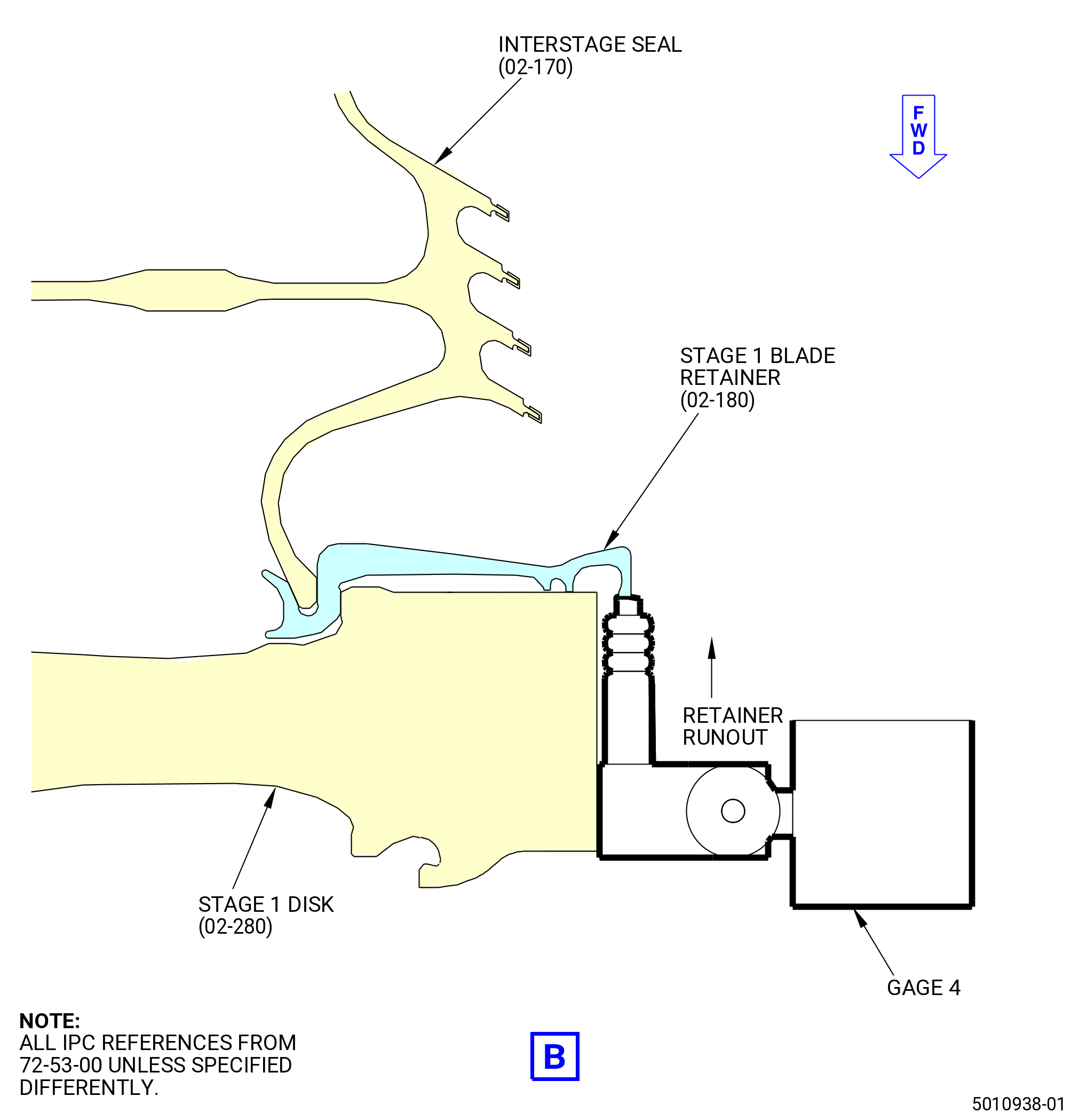
| (3) | Do a check of the runout of the aft stage 1 blade retainer (02-180) (SIN 150BB). Refer to Figure 1043 and do as follows: |
| NOTE: |
|
| (a) | Keep the gage 1 and gage 3 in position on the forward flange rabbet and forward flange face. |
| (b) | Do the tilt and center procedure if not previously done. |
| (c) | Put the lever of gage 4 on the forward face of the stage 1 blade retainer tip. |
| (d) | Press the DISPLAY GAGES button on the computer screen. |
| (e) | Adjust the gage (gage 4) to make the bar graph near zero. |
| (f) | Press the DISPLAY LINEAR PLOT button on the computer screen. |
| (g) | Make sure the gages and cables will not interfere when the rotary table is turned. |
| (h) | Turn the rotary table to collect the data. |
| (i) | Do the measurement of the stage 1 blade retainer tip as follows: |
| 1 | Press the MEASURE button on the computer screen. |
| 2 | Press the NEW RUN button on the computer screen. |
| 3 | Enter the serial number of the HPT stage 1 disk in the computer. |
| (j) | Turn the stage 2 disk (02-130) (SIN 150B1) and align the 1-1 slot on the stage 1 disk (02-280) (SIN 150A1) with the gage. |
| (k) | Press ENTER when the stage 2 disk (02-130) (SIN 150B1) and the 1-1 slot on the stage 1 disk (02-280) (SIN 150A1) and the gage are aligned. |
| (l) | Turn the rotary table two full rotations to collect the data. |
| (m) | Stop the rotary table after the data is collected. |
| (n) | Press the PRINT button on the computer screen. |
| (o) | Runout must not be more that 0.015 inch (0.38 mm). |
| WARNING: |
|
| (4) | Use and overhead hoist and lower the 11C3056 lift fixture. Refer to Figure 1044. |
| (5) | Attach the 11C3056 lift fixture to the HPT rotor assembly. |
| (6) | Lift the stage 1 HPT Rotor and put it on the 11C3024 assembly/disassembly fixture. |
| (7) | Put the collected data printout with the HPT rotor assembly. |
| Subtask 72-53-00-440-464 |
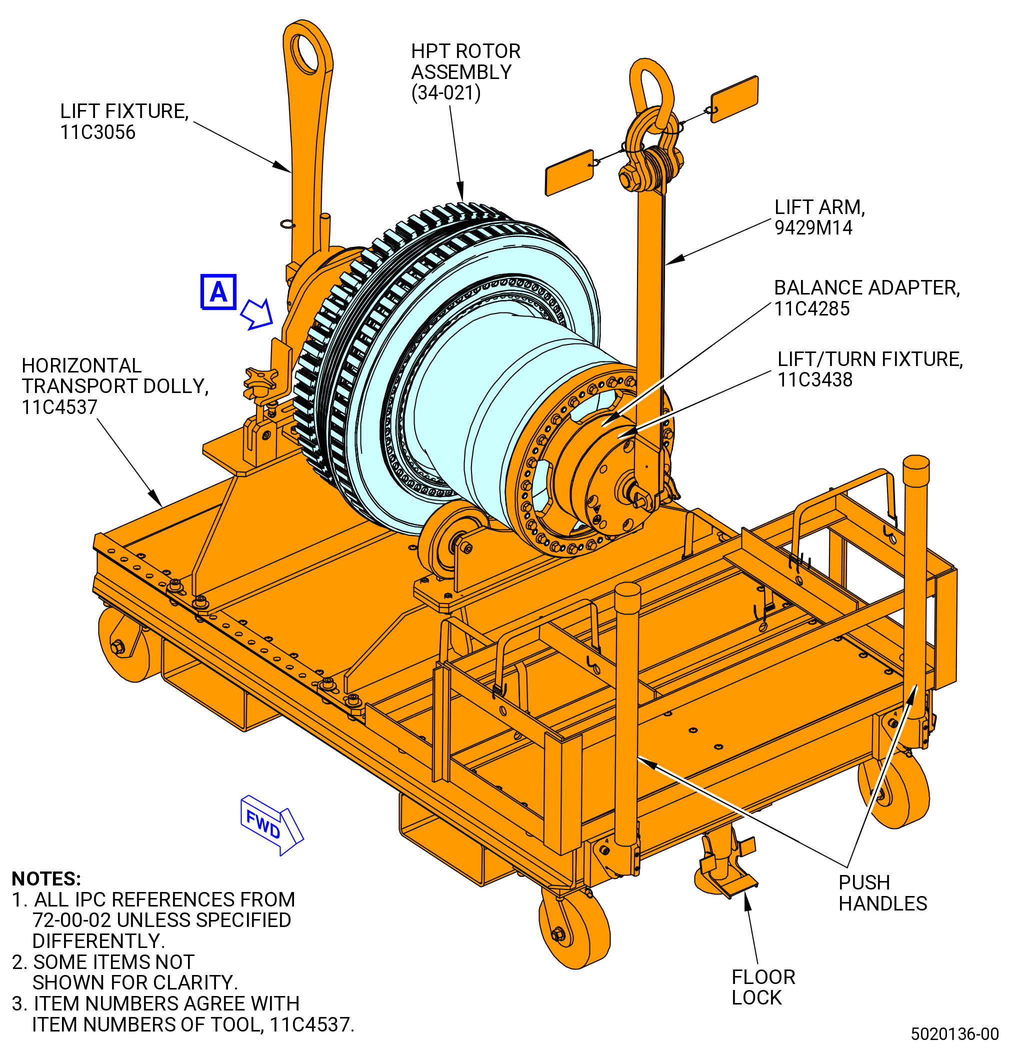
| Y. | Install the HPT rotor assembly (34-021 , 72-00-02) (SIN 15000) in the 11C4537 horizontal transport dolly. Refer to the manufacturer's instructions and do as follows: |
| (1) | Lift the HPT rotor assembly from the 11C3024 assembly/disassembly fixture. Refer to Figure 1006 and do as follows: |
| (a) | Attach the 11C3056 lift fixture to the threads on the aft end of the stage 1 disk. Turn CW, ALF, until the 11C3056 lift fixture is fully engaged on the HPT rotor shaft. |
| (b) | Attach an overhead hoist to the 11C3056 lift fixture. |
| (c) | Remove the nuts (item 14) and washers (item 20) that attach the HPT rotor assembly to the 11C3024 assembly/disassembly fixture. |
| WARNING: |
|
| (d) | Lift the HPT rotor assembly from the 11C3024 assembly/disassembly fixture. |
| (e) | Remove the retaining rings (item 8) of the 11C3024 assembly/disassembly fixture from the aft face of the forward flange of the stage 1 disk. |
| Subtask 72-53-00-440-465 |
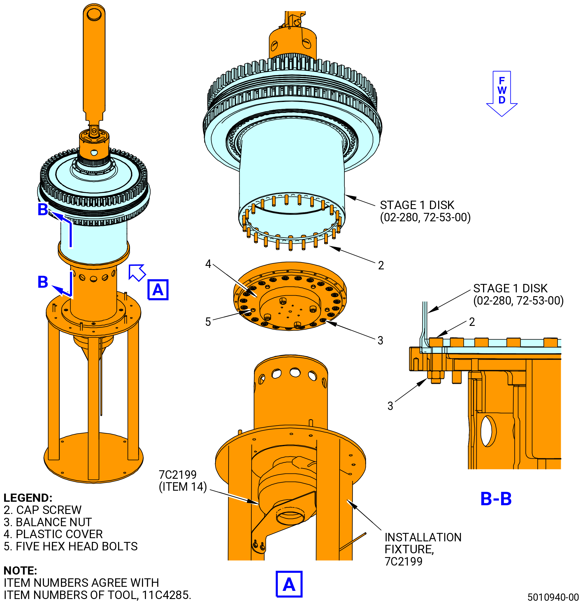
| (2) | Alternative procedure available. Install the 11C4285 balance arbor and 11C3438 lift fixture on the HPT stage 1 disk as follows: |
| (a) | Install the 11C4285 balance arbor on the stage 1 disk. Refer to Figure 1045 and do as follows: |
| WARNING: |
|
| 1 | Decrease the temperature of the forward flange of the stage 1 disk with dry ice or liquid nitrogen. |
| 2 | Clean the mating surfaces of the 11C4285 balance arbor with C04-035 isopropyl alcohol. |
| 3 | Put the 11C4285 balance arbor on the 7C2199 installation fixture. Install the arbor with the large flange up. Refer to Figure 1045. |
| 4 | Optional Procedure. Increase the temperature of the arbor to 350°F (177°C). |
| 5 | The steps that follow must be done as quickly as possible in order to make the assembly of the HPT rotor and balance arbor easier. |
| WARNING: |
|
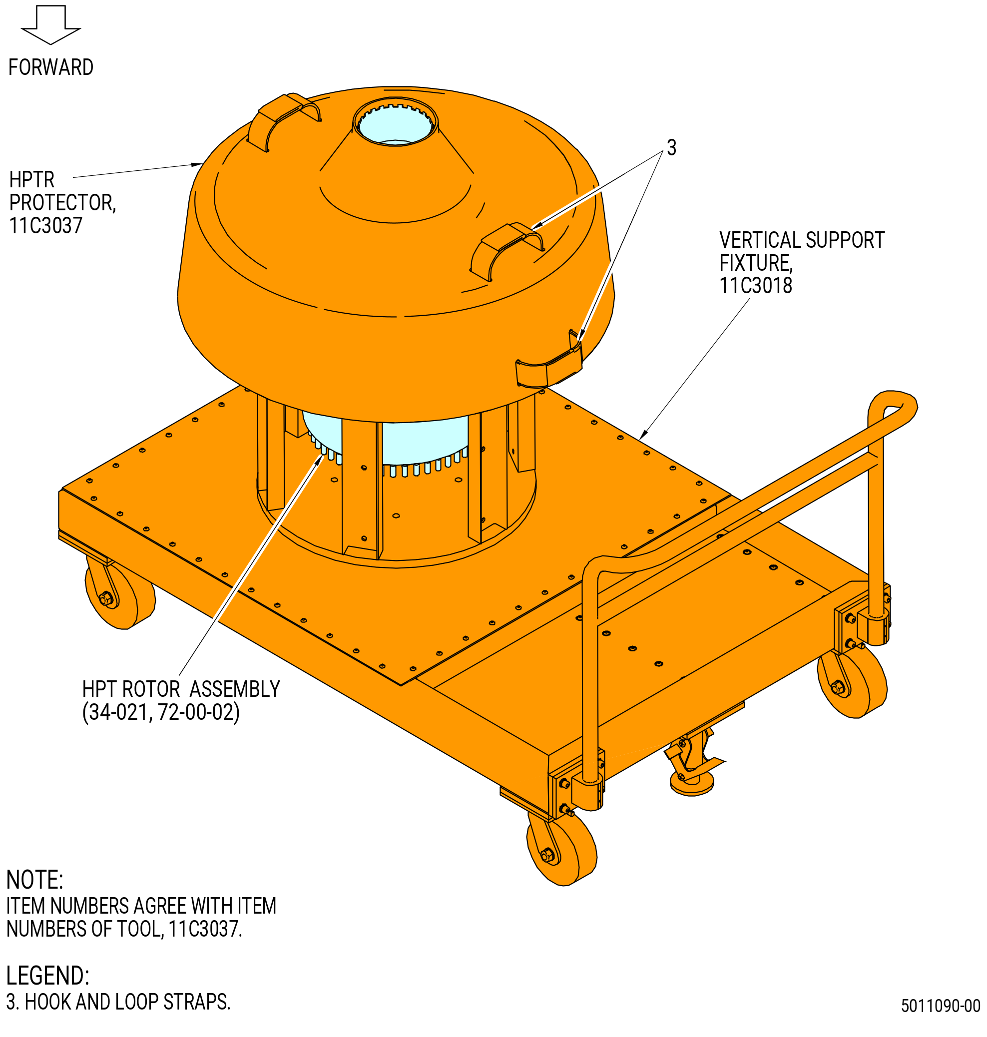
| 6 | Lift the HPT rotor assembly from the 11C3018 vertical support fixture. |
| 7 | Put the HPT rotor assembly in position above the 11C4285 balance arbor on the 7C2199 installation fixture. |
| 8 | Align the 1-1 mark on the arbor with the 1-1 slot on the HPT stage 1 disk (02-280) (SIN 150A1). |
| 9 | Lower the forward flange of the HPT stage 1 disk into the inner diameter of the arbor. |
| 10 | Adjust the HPT rotor assembly as necessary to align the boltholes of the forward flange with the boltholes in the balance arbor. |
| 11 | Push the 11C4285 balance arbor against the HPT stage 1 disk to make sure that the arbor was installed. Use rubber mallet if necessary. |
| 12 | Let the parts go back to ambient temperature. Use the fan (item 14) of the 7C2199 installation fixture to help the parts go back to room temperature. |
| WARNING: |
|
| 13 | Apply the C02-058 lubricant on the cap screw (item 2) threads. |
| 14 | Install 23 cap screws (item 2) in every hole of the arbor. Install the cap screws from inside the stage 1 disk with the bolt heads up. |
| 15 | Install a balance nut (item 3) on each cap screw. |
| 16 | Torque the balance nuts to 32 lb ft (43.4 N.m) in a criss-cross pattern. |
| WARNING: |
|
| 17 | Lift the HPT rotor assembly from the 7C2199 installation fixture. |
| 18 | Install the plastic cover (item 4) with the five hex head bolts (item 5). |
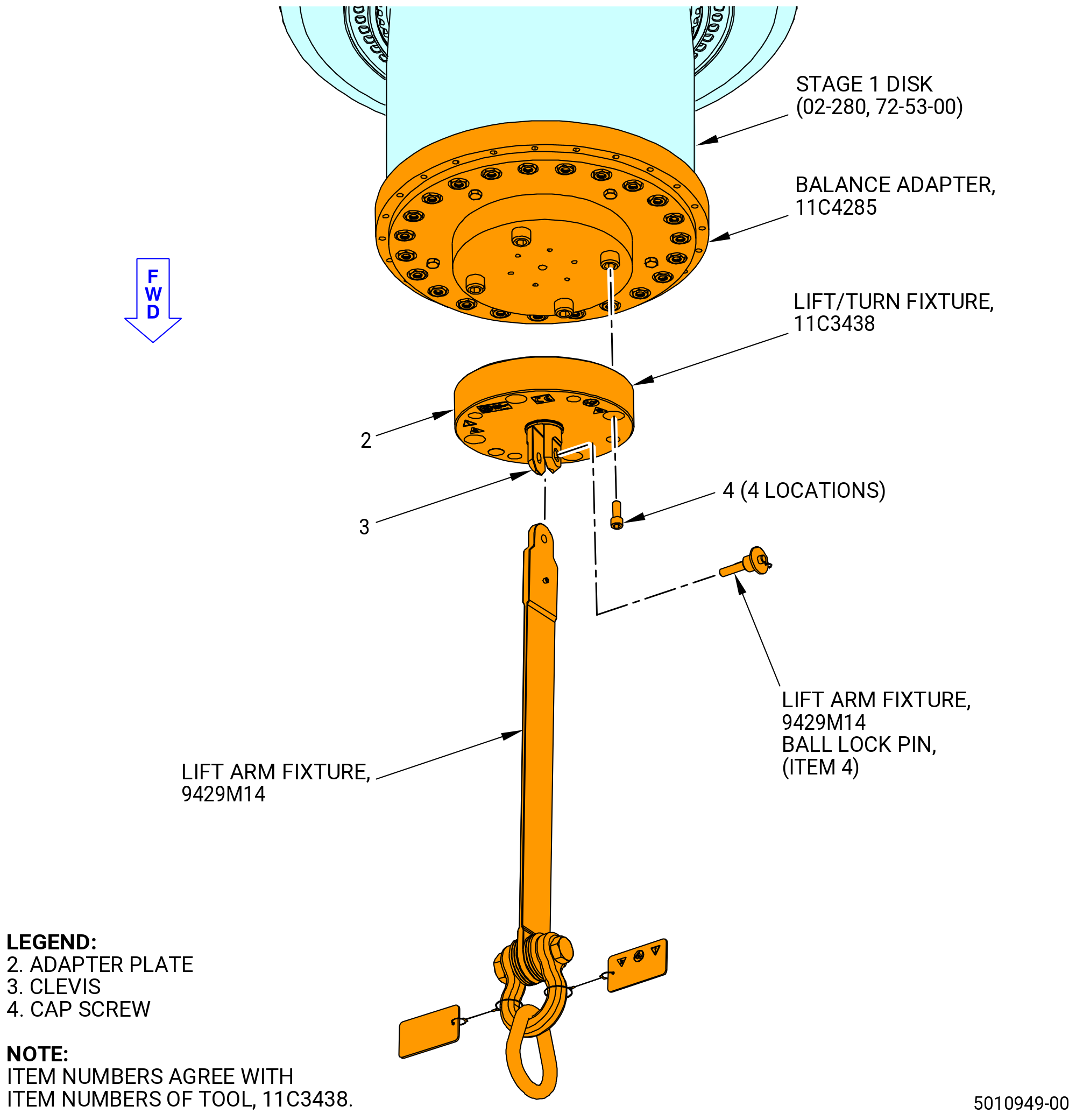
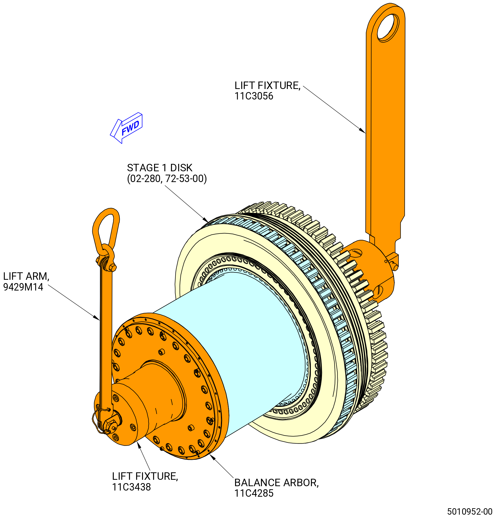
| (b) | Install the 11C3438 lift fixture and 9429M14 lift arm on the 11C4285 balance arbor. Refer to Figure 1046 and do as follows: |
| 1 | Attach the adapter plate (item 2) and clevis (item 3) to the 11C4285 balance arbor with cap screws (item 4). |
| 2 | Attach the 9429M14 lift arm fixture to the clevis (item 3) with the ball lock pin. |
| 3 | Attach an overhead hoist to the 9429M14 lift arm. |
| Subtask 72-53-00-440-466 |
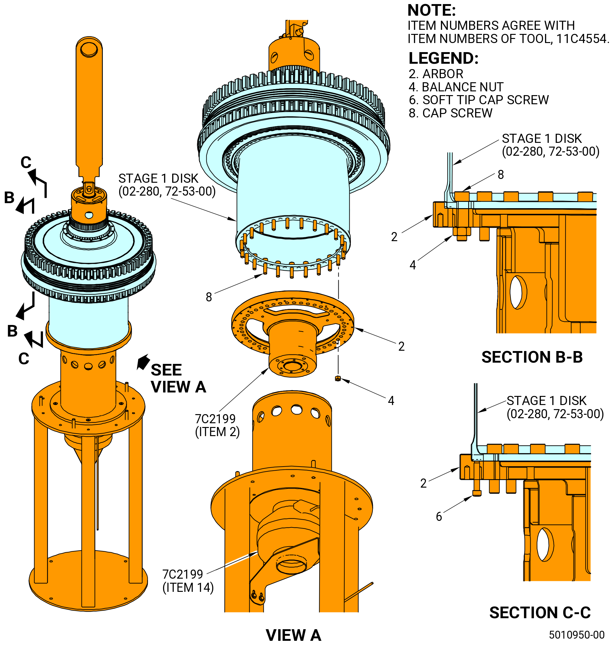
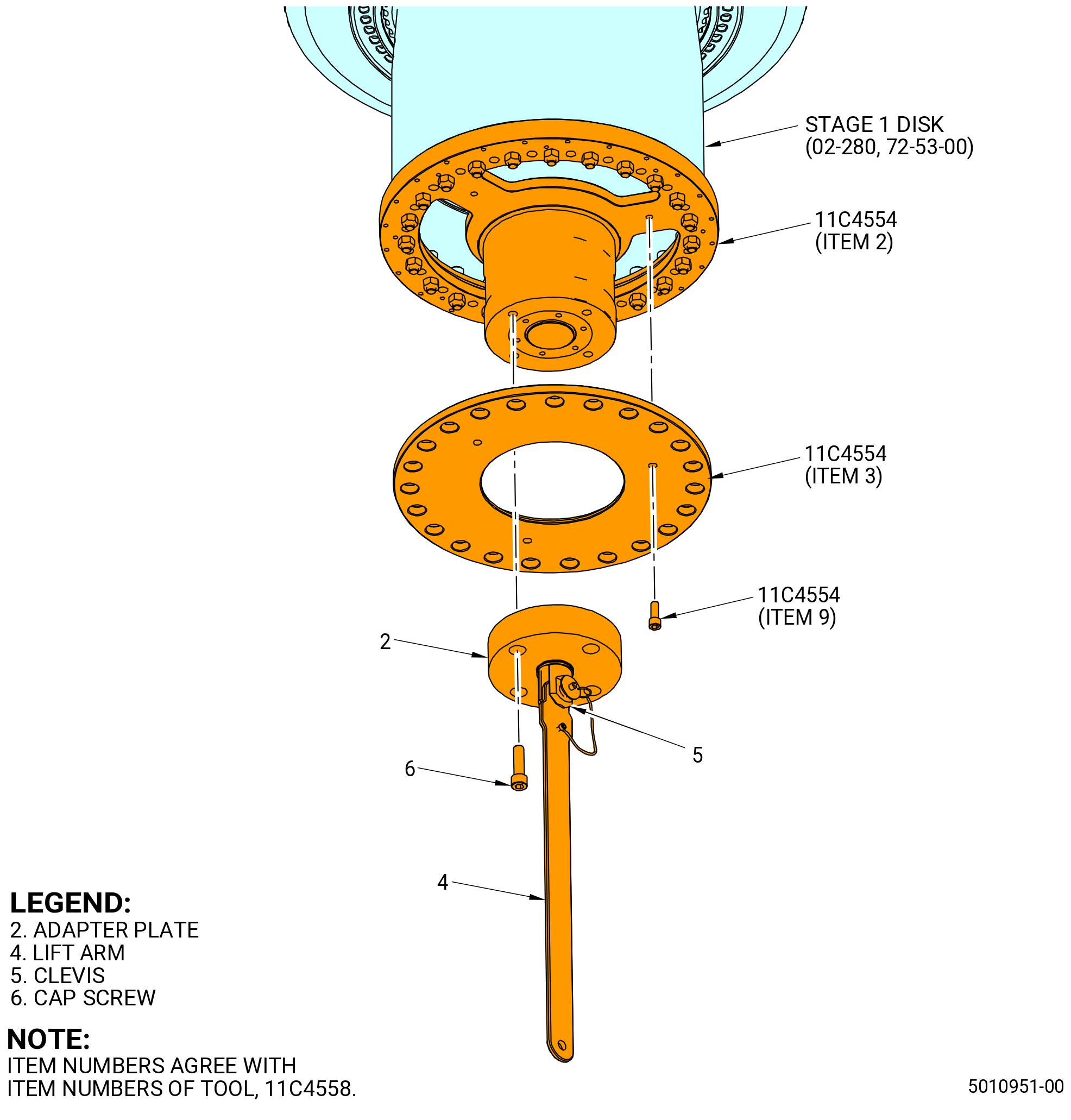
| (2).A. | Alternative Procedure. Install the 11C4554 balance arbor on the stage 1 disk. Refer to Figure 1048 and do as follows: |
| (a) | Put the HPT rotor assembly on the 11C3018 vertical support fixture. Refer to TASK 72-00-02-430-820 (72-00-02, ASSEMBLY 002 - CONFIGURATION 02). |
| WARNING: |
|
| WARNING: |
|
| (b) | Decrease the temperature of the forward flange of the stage 1 disk with dry ice or liquid nitrogen. |
| WARNING: |
|
| (c) | Clean the mating surfaces of the 11C4554 balance arbor with C04-035 isopropyl alcohol. |
| (d) | Put the arbor (item 2) of the 11C4554 balance arbor on the 7C2199 installation fixture. Install the arbor with the large flange up. Refer to Figure 1048. |
| (e) | Increase the temperature of the arbor to 350°F (177°C). |
| WARNING: |
|
| (f) | Install the HPT rotor assembly onto the 11C4554 balance arbor as follows: |
| NOTE: |
|
| 1 | Lift the HPT rotor assembly from the 11C3018 vertical support fixture. |
| 2 | Put the HPT rotor assembly in position above the 11C4554 balance arbor on the 7C2199 installation fixture. |
| 3 | Align the 1-1 mark on the arbor (item 2) with the 1-1 slot on the stage 1 disk (02-280) (SIN 150A1). |
| 4 | Lower the forward flange of the stage 1 disk into the inner diameter of the arbor (item 2). |
| 5 | Adjust the HPT rotor assembly as necessary to align the boltholes of the forward flange with the boltholes in the balance arbor. Use a cap screw (item 8) of the 11C4554 balance arbor to make sure the boltholes align. |
| (g) | Let the parts go back to ambient temperature. Use the fan (item 14) of the 7C2199 installation fixture to help the parts go back to room temperature. |
| (h) | Install 23 cap screws (item 8) in every other hole of the arbor (item 2). Install the cap screws from inside the stage 1 disk with the bolt heads up. |
| CAUTION: |
|
| (i) | Install a balance nut (item 4) on each cap screw (item 8). |
| (j) | Tighten the balance nuts (item 4) to 32 lb ft (43.4 N.m) in a criss-cross pattern. |
| (k) | Lift the HPT rotor assembly from the 7C2199 installation fixture. |
| (l) | Install the dust cover (item 3) of the 11C4554 balance arbor on the arbor (item 2) with cap screws (item 9). Refer to Figure 1049. |
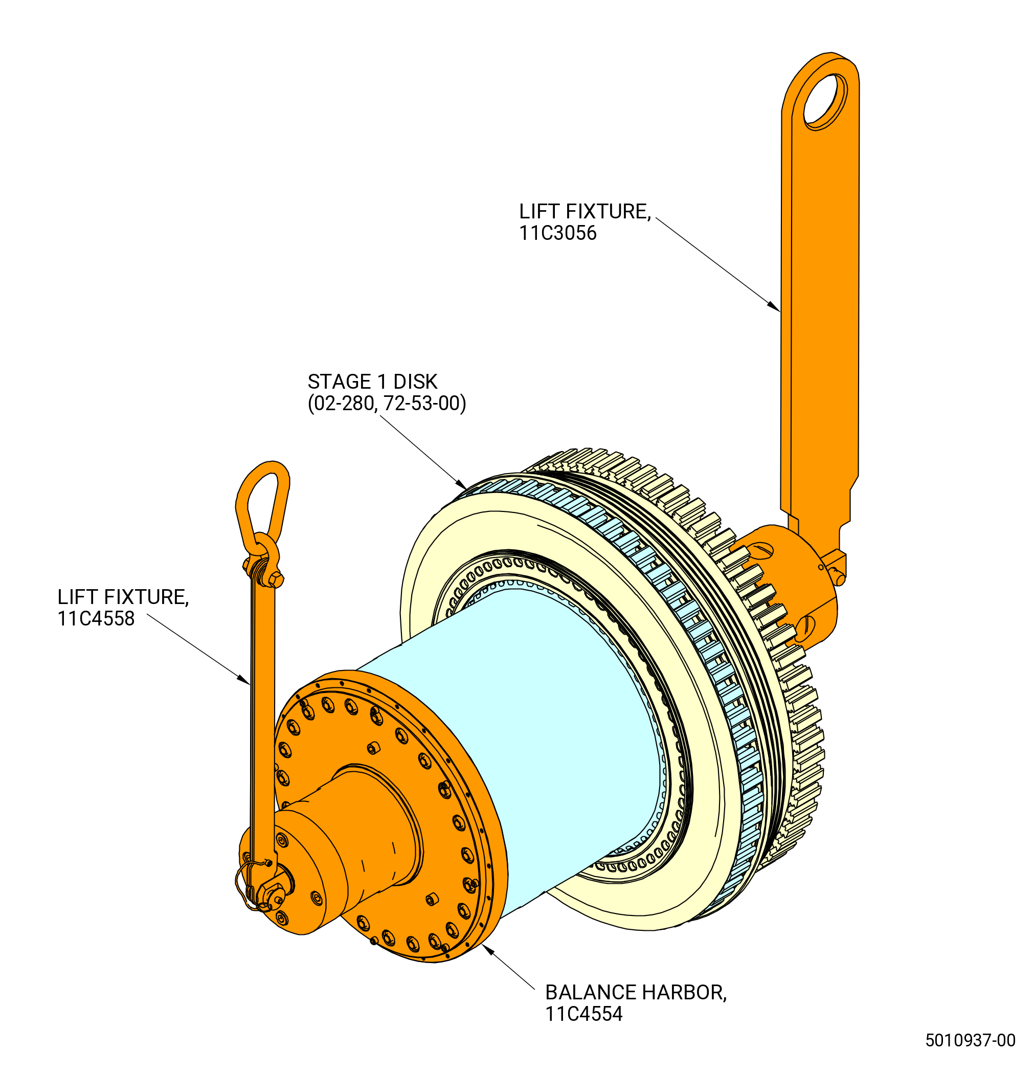
| (m) | Install the 11C4558 lift fixture on the 11C4554 balance arbor as follows: |
| 1 | Remove the ball lock pin and remove the lift arm (item 4). |
| 2 | Attach the adapter plate (item 2) and clevis (item 5) to the 11C4554 balance arbor with cap screws (item 6). |
| 3 | Attach the lift arm (item 4) to the clevis (item 5) with the ball lock pin. |
| 4 | Attach an overhead hoist to the lift arm (item 4). |
| CAUTION: |
|
| (3) | Lift the forward end of the HPT rotor assembly and lower the aft end until the HPT rotor assembly is horizontal. Refer to Figure 1049. |
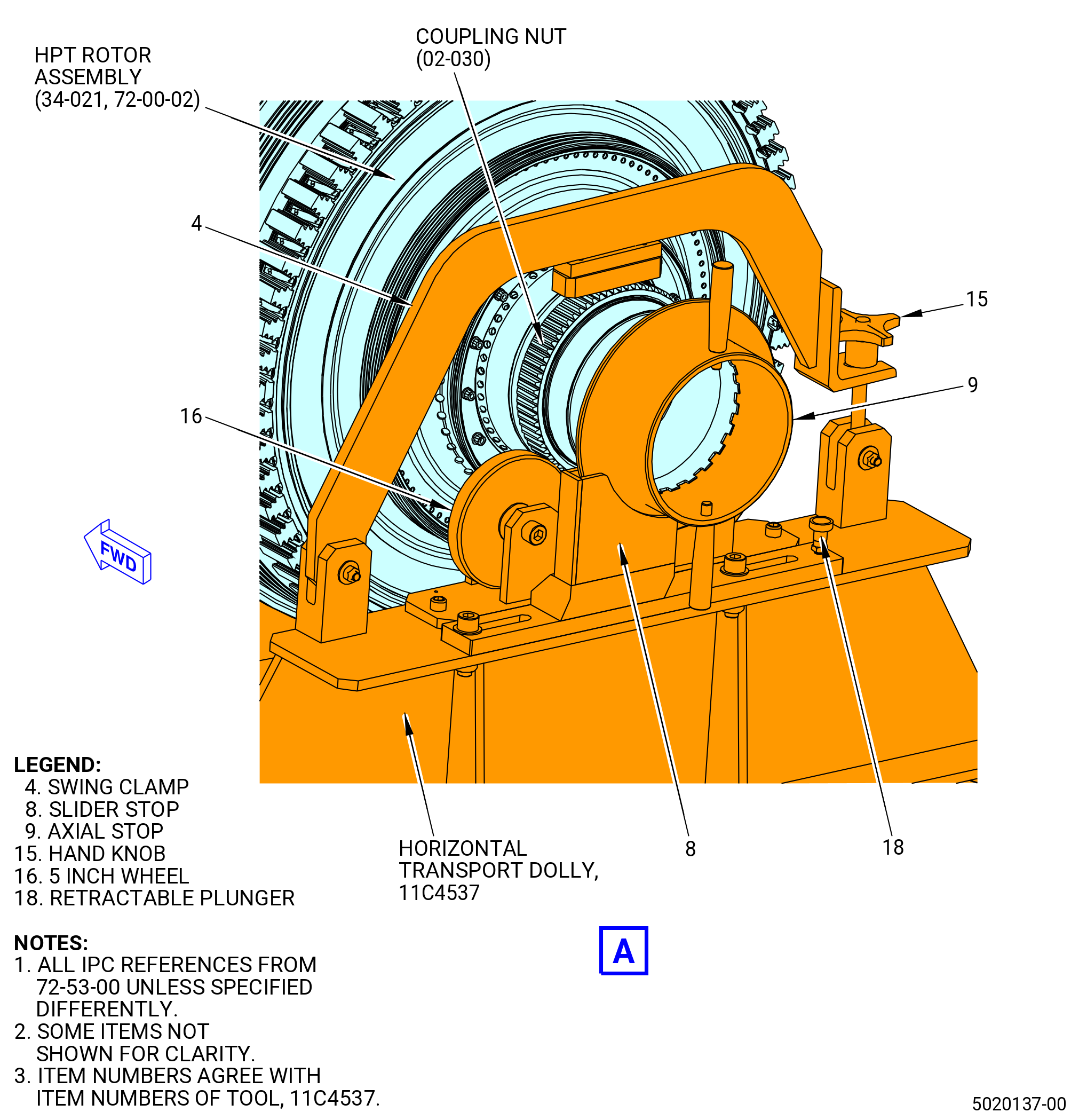
| (4) | Put the HPT rotor assembly (34-021 , 72-00-02) (SIN 15000) on the 11C4537 horizontal transport dolly. Refer to Figure 1047 and do as follows: |
| (a) | Engage floor locks and open the swing clamp (item 4) of the 11C4537 horizontal transport dolly. |
| (b) | Release the retractable plunger (item 18) and move the slider stop (item 8) out. |
| (c) | Put the HPT rotor assembly on the 11C4537 horizontal transport dolly and make sure that the forward end points to the push handles. |
| 1 | Put the HPT rotor assembly in a position to make sure that the coupling nut (02-030) (SIN 150AD) sits on the 5 inch wheel (item 16). |
| (d) | Optional procedure. Prevent the HPT rotor assembly from axial movement as follows: |
| 1 | Install the axial stop (item 9) of the 11C4537 horizontal transport dolly on the aft shaft of the HPT rotor assembly. |
| 2 | Move the slider stop (item 8) in and lock it with the retractable plunger (item 18). |
| 3 | If necessary, adjust the axial stop (item 9). |
| (e) | Close the swing clamp (item 4) and tighten it with the hand knob (item 15). |
| Subtask 72-53-00-440-467 |
| Z. | Deleted. |
| Subtask 72-53-00-440-468 |
| NOTE: |
|
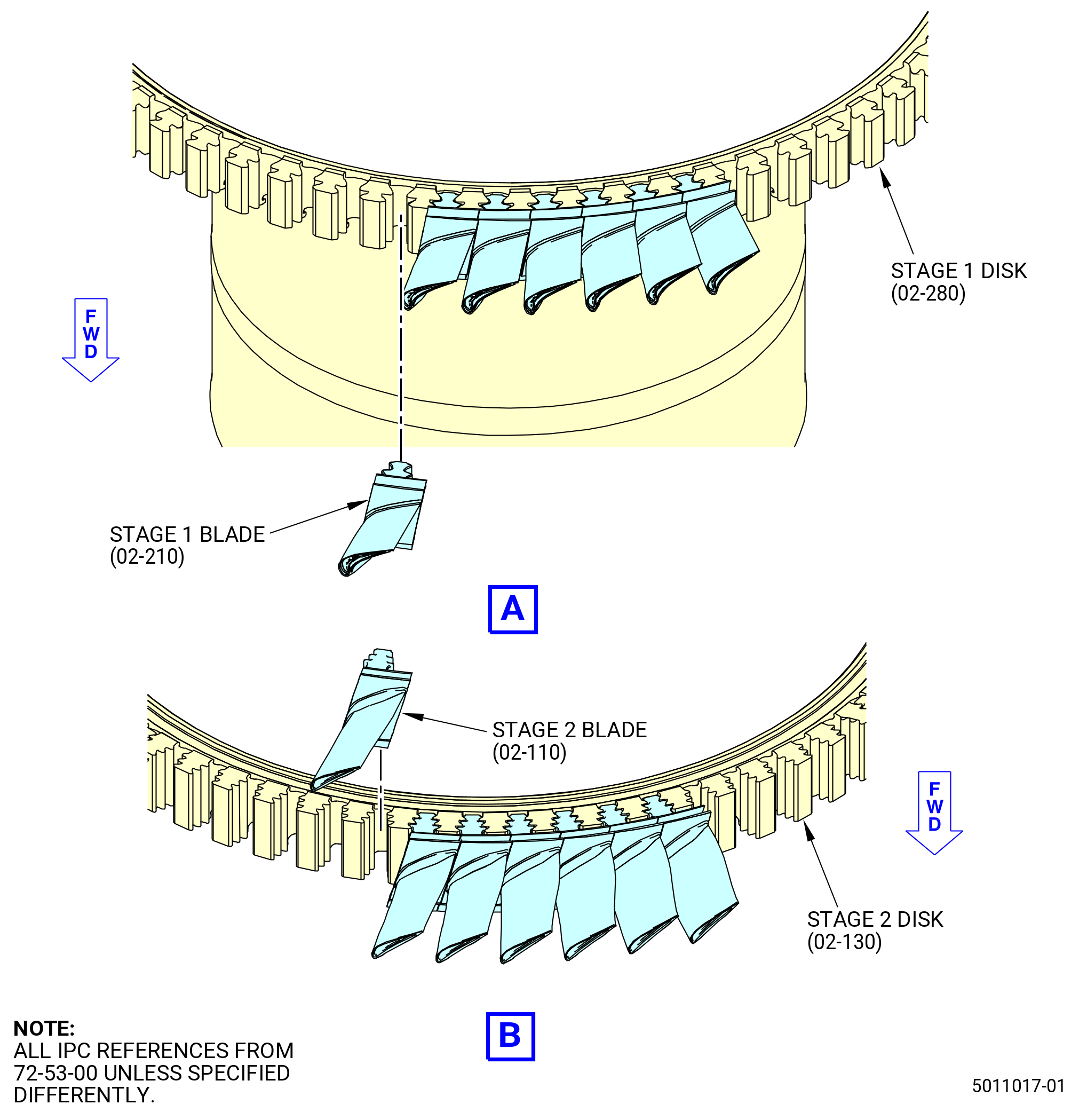
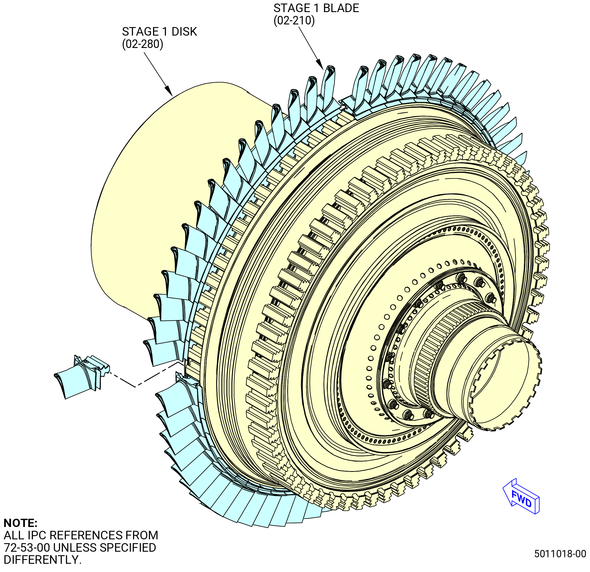
| AA. | Alternative Procedure Available. Install the stage 1 blades (02-210) (SIN 150A0). Refer to Figure 1052 and do as follows: |
| (1) | Prepare the stage 1 blades (02-210) (SIN 150A0) for installation as follows: |
| (a) | Use a C05-003 marking pen and mark each stage 1 blade from 1-62. |
| (b) | Pan weigh the stage 1 blades from 1-62. |
| (c) | Make a plot of the stage 1 blades for the minimum amount of unbalance possible. |
| (d) | Record the weight and mark it on each tip of the stage 1 blades. |
| (2) | Install the stage 1 blades into the stage 1 disk (02-280) (SIN 150A1) as follows: |
| (a) | Do a visual inspection to make sure that the four seal rings (02-200) (SIN 150N2) are fully seated in the groove on the forward face of the stage 1 blade retainer (02-180) (SIN 150BB) before each of the stage 1 blades is installed. |
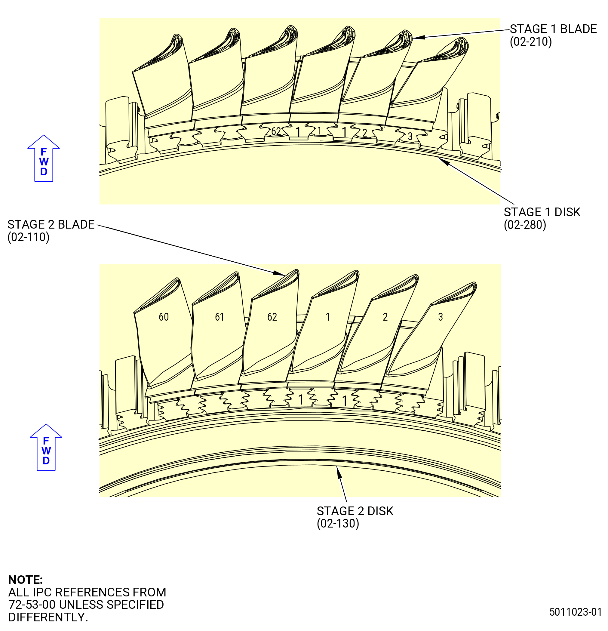
| (b) | Install the first stage 1 blade (02-210) (SIN 150A0), in the order shown on the stage 1 blades plot, in the 1-1 dovetail slot of the stage 1 disk (02-280) (SIN 150A1). |
| (c) | Make sure that the leading edge of the stage 1 blade points forward. |
| (d) | Continue to install the stage 1 blades. |
| (e) | To install the last stage 1 blade, move approximately 15 blades forward in the dovetail slot, a small distance until the last stage 1 blade can be installed. |
| (f) | Push the stage 1 blades back into position. |
| (g) | Make sure that the stage 1 blades are against the stage 1 blade retainer (02-180) (SIN 150BB). |
| Subtask 72-53-00-440-533 |
| NOTE: |
|
| AA.A. | Alternative procedure. Install the stage 1 blades (02-210) (SIN 150A0) and the stage 1 dampers (02-220) (SIN 150AB) into the stage 1 disk (02-280) (SIN 150A1). Refer to Subtask 72-53-00-440-485 (paragraph 3.AP.). |
| Subtask 72-53-00-440-469 |
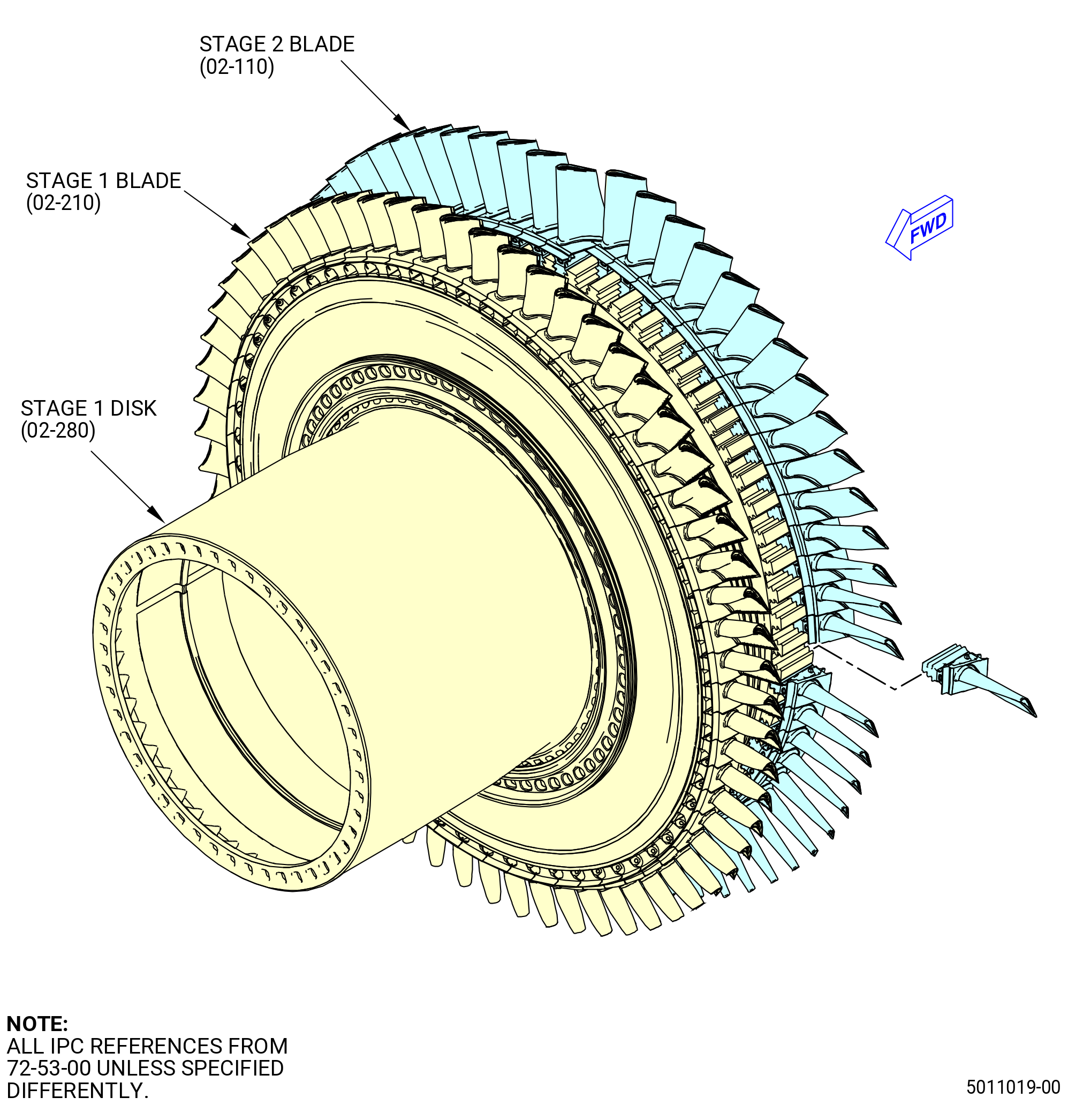
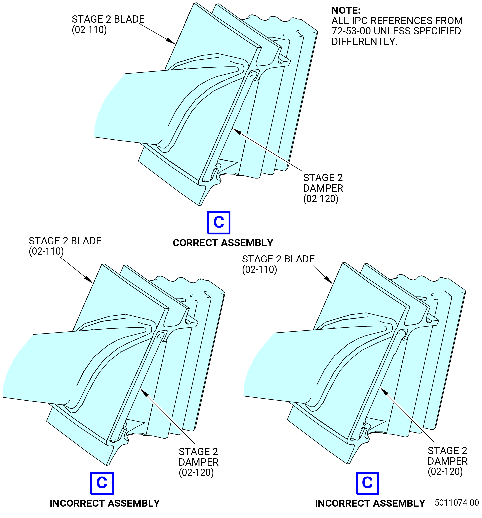
| AB. | Install the stage 2 blades (02-110) (SIN 150B0). Refer to Figure 1052 and do as follows: |
| (1) | Prepare the stage 2 blades for installation as follows: |
| (a) | Use a C05-003 marking pen and mark each stage 2 blade from 1-62. |
| (b) | Pan weigh the stage 2 blades from 1-62. |
| (c) | Make a plot of the stage 2 blades for the minimum amount of unbalance possible. |
| (d) | Record the weight and mark it on each stage 2 blade tip. |
| (2) | Install the stage 2 blades in the stage 2 disk (02-130) (SIN 150B1) as follows: |
| (a) | Install the first stage 2 blade, in the order shown, in the 1-1 dovetail slot of the stage 2 disk (02-130) (SIN 150B1). |
| (b) | Make sure that the leading edge of the stage 2 blade points to the forward end of the stage 1 disk (02-280) (SIN 150A1). |
| (c) | Continue to install the stage 2 blades. |
| (d) | To install the last stage 2 blade, move approximately 15 blades aft in the dovetail slot, a small distance until the last stage 2 blade can be installed. |
| (e) | Push the stage 2 blades back into position. |
| (f) | Make sure that the stage 2 blades are against the interstage seal (02-170) (SIN 150B3). |
| Subtask 72-53-00-440-470 |
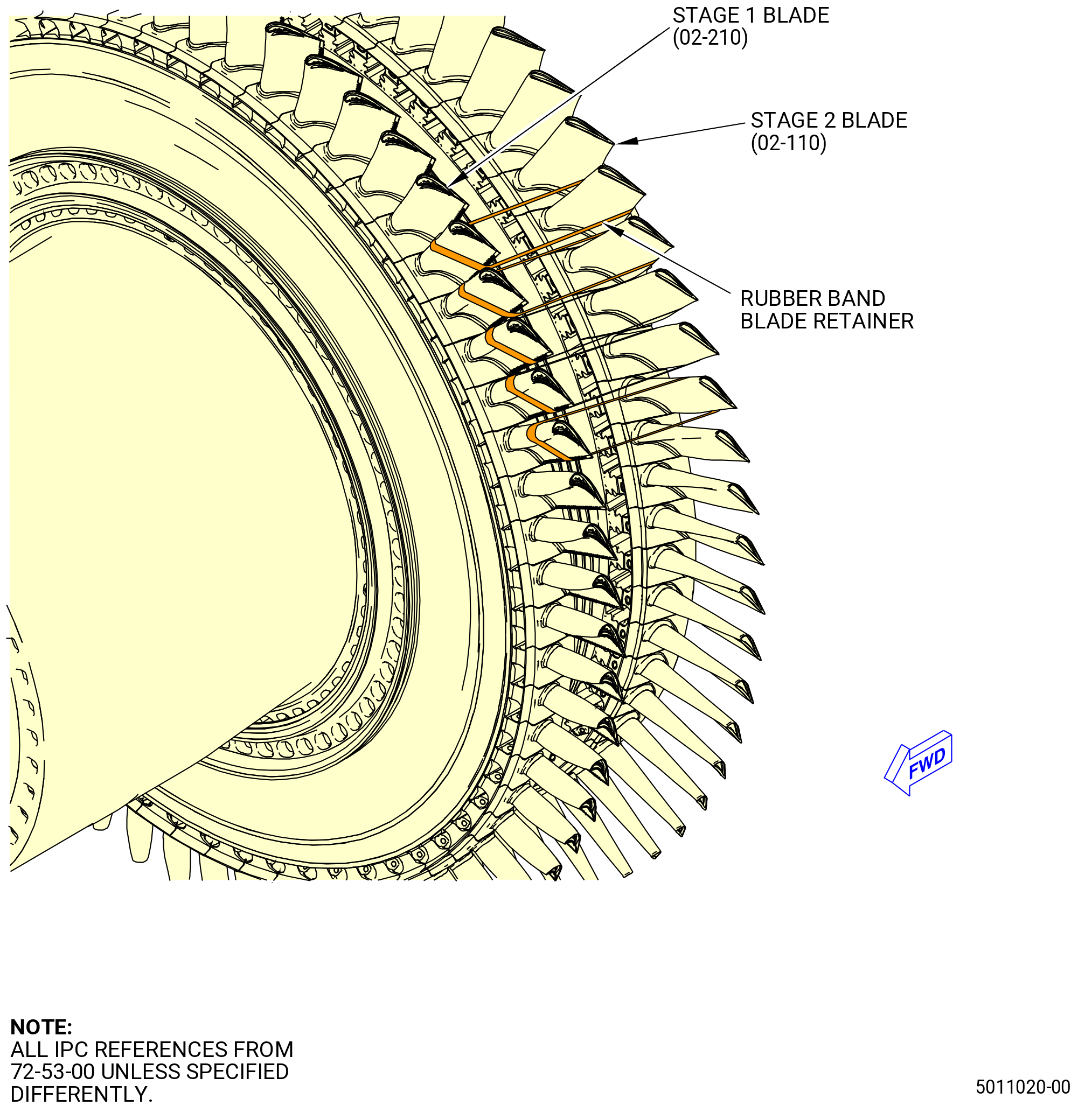
| AC. | Optional Procedure. This procedure needs to be accomplished, if Subtask 72-53-00-440-471 (paragraph 3.AD.) (green balancing) is being accomplished. Install the rubber band blade retainers to hold the stage 1 blades (02-210) (SIN 150A0) and the stage 2 blades (02-110) (SIN 150B0). Refer to Figure 1053 and do as follows: |
| CAUTION: |
|
| (1) | Make sure that you have the correct size No. 32 rubber bands. |
| (2) | Install two size No. 32 rubber bands around the front side of one stage 1 blade and pull it around the aft side of one adjacent stage 2 blade. Push the rubber bands down to the blade platforms. |
| (3) | Continue this procedure until all 62 stage 1 blades and 62 stage 2 blades are retained with size No. 32 rubber bands. |
| (4) | Make sure that all of the stages 1 and 2 blades are correctly retained. |
| Subtask 72-53-00-440-471 |
| AD. | Optional Procedure. Do a green balance of the HPT rotor assembly (34-021 , 72-00-02) (SIN 15000) as follows: |
| (1) | Move the HPT rotor assembly (34-021 , 72-00-02) (SIN 15000) from the 11C4537 horizontal transport dolly to the balance machine. |
| (a) | Attach the overhead hoist to the 11C3056 lift fixture and the 11C4558 lift fixture or the 9429M14 lift arm. |
| WARNING: |
|
| (b) | Lift the HPT rotor assembly from the 11C4537 horizontal transport dolly. |
| (c) | Put the HPT rotor assembly on the balance machine. Refer to the balance machine manufacturer's instructions for the installation of the HPT rotor assembly on the balance machine. |
| (d) | Remove the 11C4558 lift fixture or the 9429M14 lift arm and the 11C3056 lift fixture from the HPT rotor assembly. |
| (2) | Refer to the balance machine manufacturer's instructions to do a green balance of the HPT rotor assembly as follows: |
| WARNING: |
|
| (a) | Operate the balance machine at 750 rpm (minimum of 700 rpm). |
| (b) | Cycle the balance machine, to 750 rpm, 2-3 times, to let the blades settle in position before proceeding. |
| WARNING: |
|
| (c) | Apply a light coat of C02-019 engine oil or C02-023 engine oil to the balance rollers. |
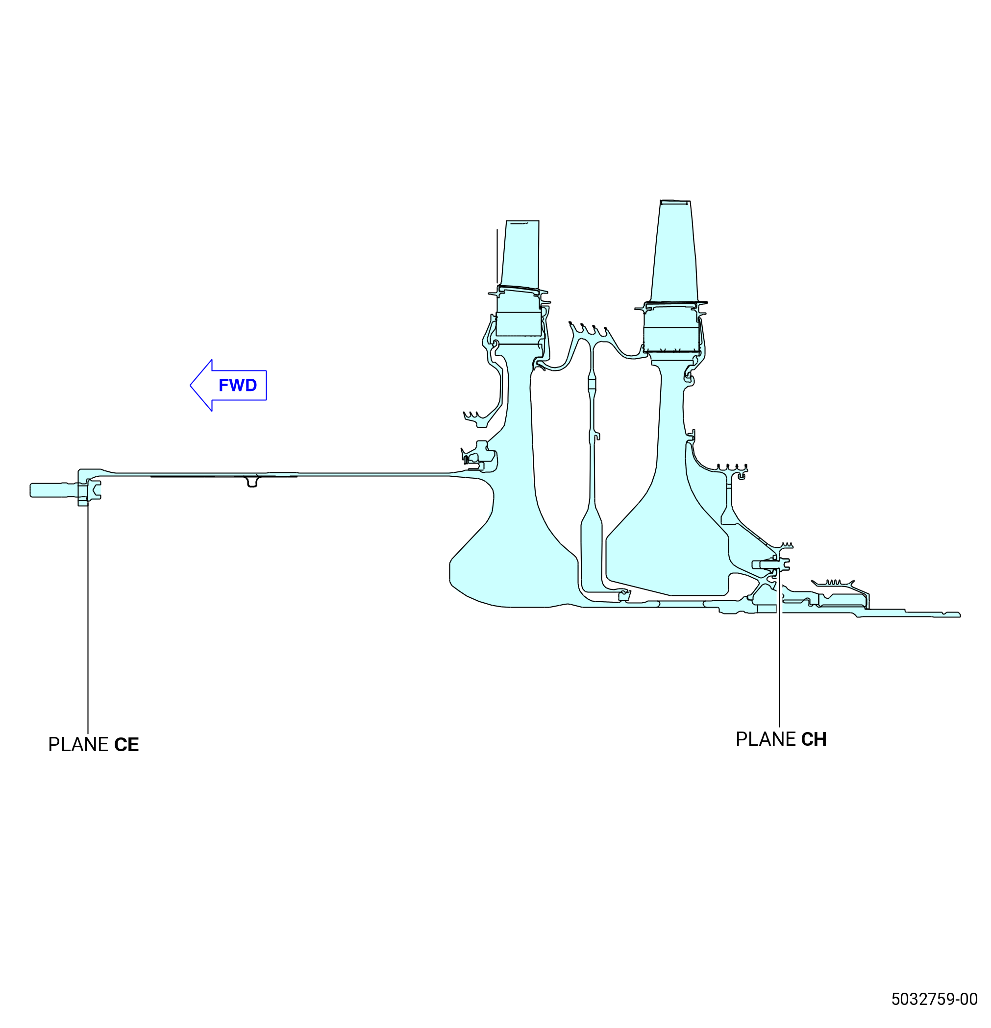
| (d) | Make a two-plane setup to read in the planes of the plane CG, stage 1 blades (02-210) (SIN 150A0), and plane CJ and stage 2 blades (02-110) (SIN 150B0). |
| (e) | Balance to a maximum of 100 gram inches in the planes of the stage 1 blades and stage 2 blades. |
| (f) | Change the stage 1 blades and stage 2 blades from one position to another as necessary for the correct balance. |
| (g) | Record the final magnitude of imbalance in gram inches and the angle in degrees of each balance plane. Refer to Figure 1054. |
| (h) | Deleted. |
| (i) | Deleted. |
| (j) | Number the stage 1 blades and the stage 2 blades. Refer to Figure 1056 and do as follows: |
| 1 | Use a C05-003 marking pen to mark the stage 1 blades (02-210) (SIN 150A0) from 1-62 in a counterclockwise (CCW) direction, forward looking aft (FLA). Refer to TASK 70-16-02-350-017 (TEMPORARY MARKING). |
| 2 | Use a C05-003 marking pen to mark the stage 2 blades (02-110) (SIN 150B0) from 1-62 in a CW direction, ALF. Refer to TASK 70-16-02-350-017 (TEMPORARY MARKING). |
| (3) | Install the HPT rotor assembly (34-021 , 72-00-02) (SIN 15000) in the 11C4537 horizontal transport dolly. Refer to the manufacturer's instructions and do as follows: |
| (a) | Attach the 11C3056 lift fixture to the HPT rotor assembly and attach an overhead hoist to the lift bar (item 4). |
| WARNING: |
|
| (b) | Use a second overhead hoist and attach it to the lift bar (item 5) of the 11C3060 lift/turn fixture. |
| (c) | Lift the HPT rotor assembly from the balance machine and put the HPT rotor assembly in the 11C4537 horizontal transport dolly. |
| (d) | Remove the 11C3060 lift/turn fixture and the 11C3056 lift fixture from the HPT rotor assembly. |
| Subtask 72-53-00-440-472 |
| AE. | Deleted. |
| Subtask 72-53-00-440-473 |
| AF. | Deleted. |
| Subtask 72-53-00-220-196 |
| AG. | Deleted. |
| Subtask 72-53-00-220-197 |
| (4) | Deleted. |
| Subtask 72-53-00-440-474 |
| CAUTION: |
|
| AH. | Prepare the HPT rotor assembly (34-021 , 72-00-02) (SIN 15000) for grinding as follows: |
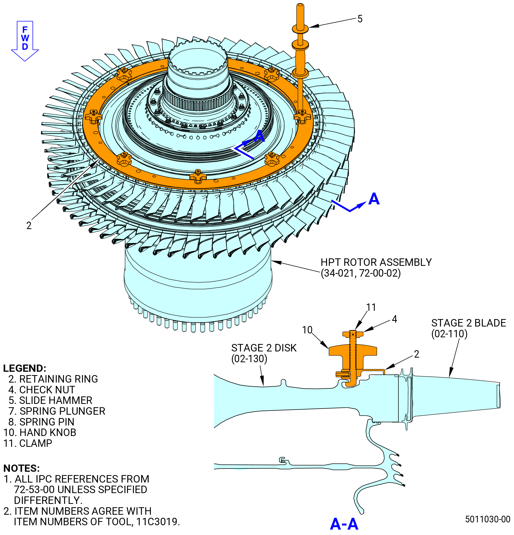
| (1) | Install the 11C3019 slave blade retainer on the stage 2 disk (02-130) (SIN 150B1) as follows: |
| (a) | If not installed already, install the rubber band blade retainers to hold the stage 1 blades (02-210) (SIN 150A0) and stage 2 blades (02-110) (SIN 150B0). Refer to Subtask 72-53-00-440-470 (paragraph 3.AC.). |
| (b) | Install the aft lift fixture of the balance tooling and align the 11C3019 slave blade retainer as follows: |
| 1 | Make sure that the nut supplied with the balance tooling is still on the HPT rotor shaft. |
| 2 | Install the aft lift fixture supplied with the balance tooling on the nut. Attach the handling arm supplied with the balance tooling to the aft lift fixture. |
| 3 | Put the 11C3019 slave blade retainer in position with the handling arm through the center of the tool. Attach the handling arm to an overhead hoist. |
| NOTE: |
|
| 4 | Make sure that the 11C3019 slave blade retainer is held captive by the lift equipment and the correct side of the retaining ring (item 2) will be against the stage 2 disk when you turn the HPT rotor assembly. Refer to Figure 1065. |
| (c) | Lift the HPT rotor assembly a sufficient amount to install the 11C3019 slave blade retainer as follows: |
| CAUTION: |
|
| CAUTION: |
|
| NOTE: |
|
| 1 | Hold the 11C3019 slave blade retainer away from tooling and engine hardware when you lift the HPT rotor assembly. |
| WARNING: |
|
| CAUTION: |
|
| 2 | Lift the HPT rotor assembly until the aft end is in a position where you can install the 11C3019 slave blade retainer (aft end approximately 45 degrees up from the horizontal position). |
| WARNING: |
|
| (d) | Assemble the 11C3019 slave blade retainer on the stage 2 disk. Refer to Figure 1065 and do as follows: |
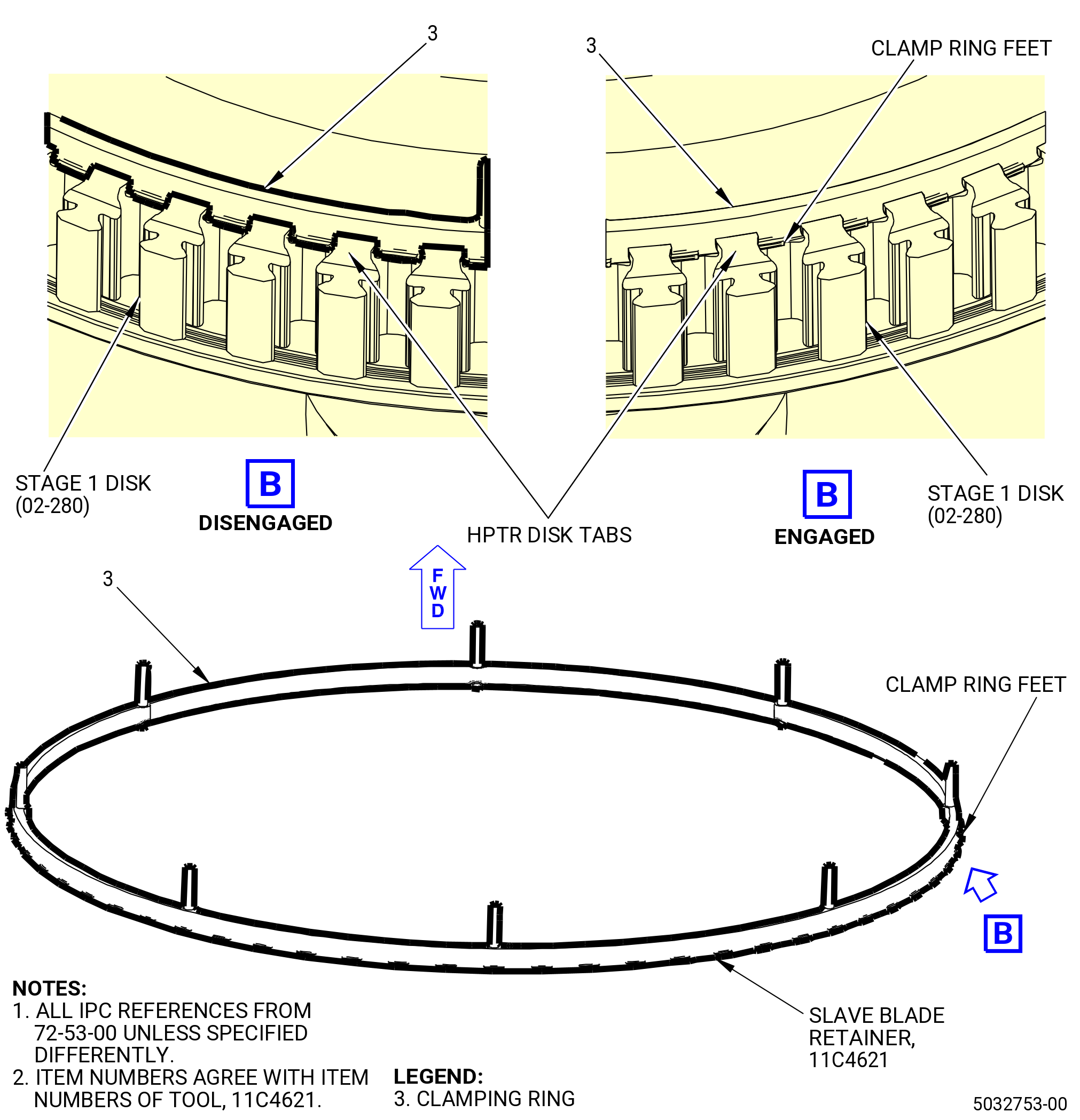
| 1 | Make sure that the clamps (item 11) are in the DISENGAGED position as marked on the retaining ring (item 2). |
| 2 | Align the 11C3019 slave blade retainer on the stage 2 disk and turn the hand knobs (item 10) to put the clamps (item 11) in the ENGAGED position. |
| 3 | Make sure that the clamps (item 11) engage the disk posts. |
| CAUTION: |
|
| 4 | Turn the hand knobs (item 10) opposite from each other around the circumference to tighten the clamps (item 11). Tighten these at approximately the same rate. |
| 5 | Lightly hit the 11C3019 slave blade retainer with a non-metallic mallet as you tighten the hand knobs (item 10). |
| 6 | Continue this procedure until the 11C3019 slave blade retainer is fully against the stage 2 disk. |
| (e) | Make sure that the 11C3019 slave blade retainer is correctly installed as follows: |
| 1 | Measure the distance between the 11C3019 slave blade retainer and the stage 2 disk with a 0.001 inch (0.03 mm) shim. |
| 2 | Make sure that there is no gap. |
| 3 | If there is a gap, remove the 11C3019 slave blade retainer and install it again. |
| (2) | Install the HPT rotor assembly in the 11C3024 assembly/disassembly fixture as follows: |
| WARNING: |
|
| (a) | Lift the HPT rotor assembly from the inspection fixture in the horizontal position with forward and aft lift fixtures supplied with the balance machine. |
| (b) | Deleted. |
| CAUTION: |
|
| CAUTION: |
|
| NOTE: |
|
| (c) | Turn the HPT rotor assembly to the vertical position, aft end down. |
| (d) | Remove the handling arm and aft lift fixture of the balance tooling. |
| (e) | Make sure that the disk bore protector (item 10) of the 11C3024 assembly/disassembly fixture is installed. Refer to Figure 1005. |
| (f) | Lower the HPT rotor assembly to the 11C3024 assembly/disassembly fixture. Refer to Figure 1062. |
| Subtask 72-53-00-440-520 |
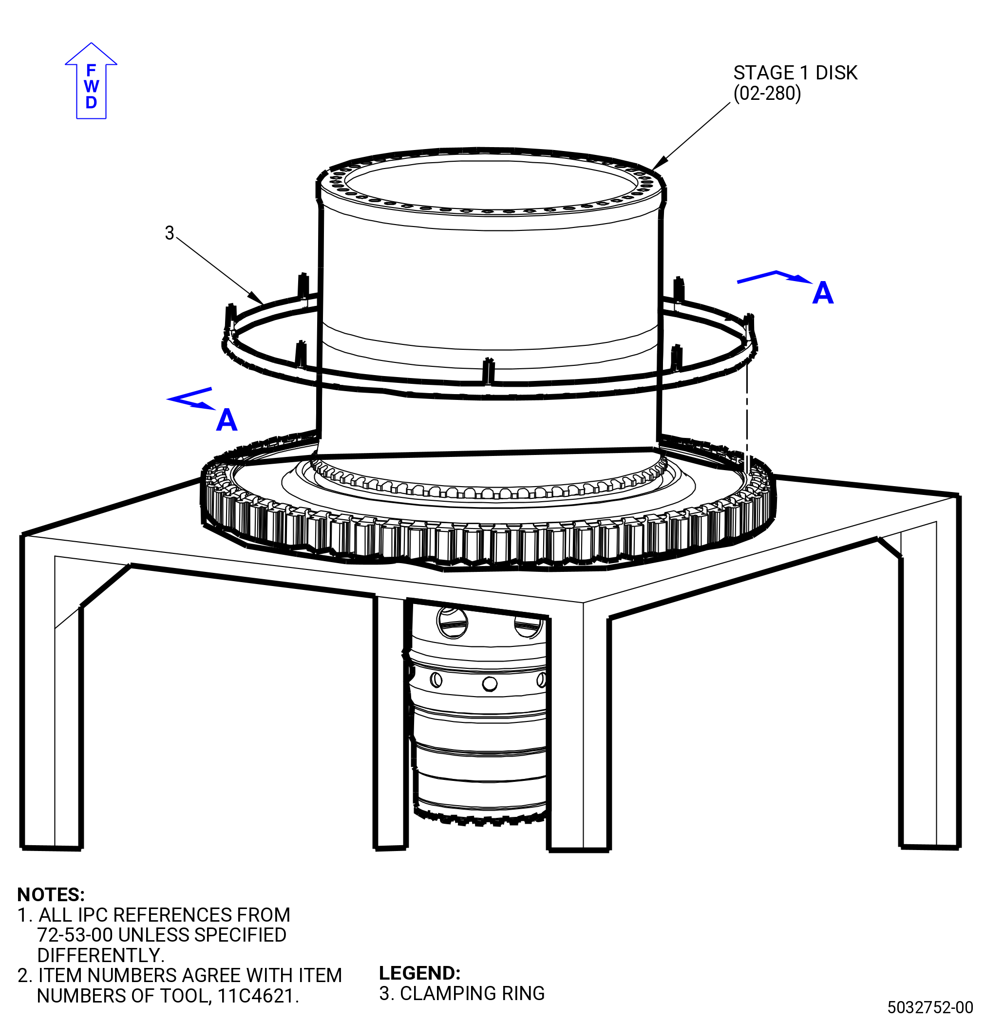
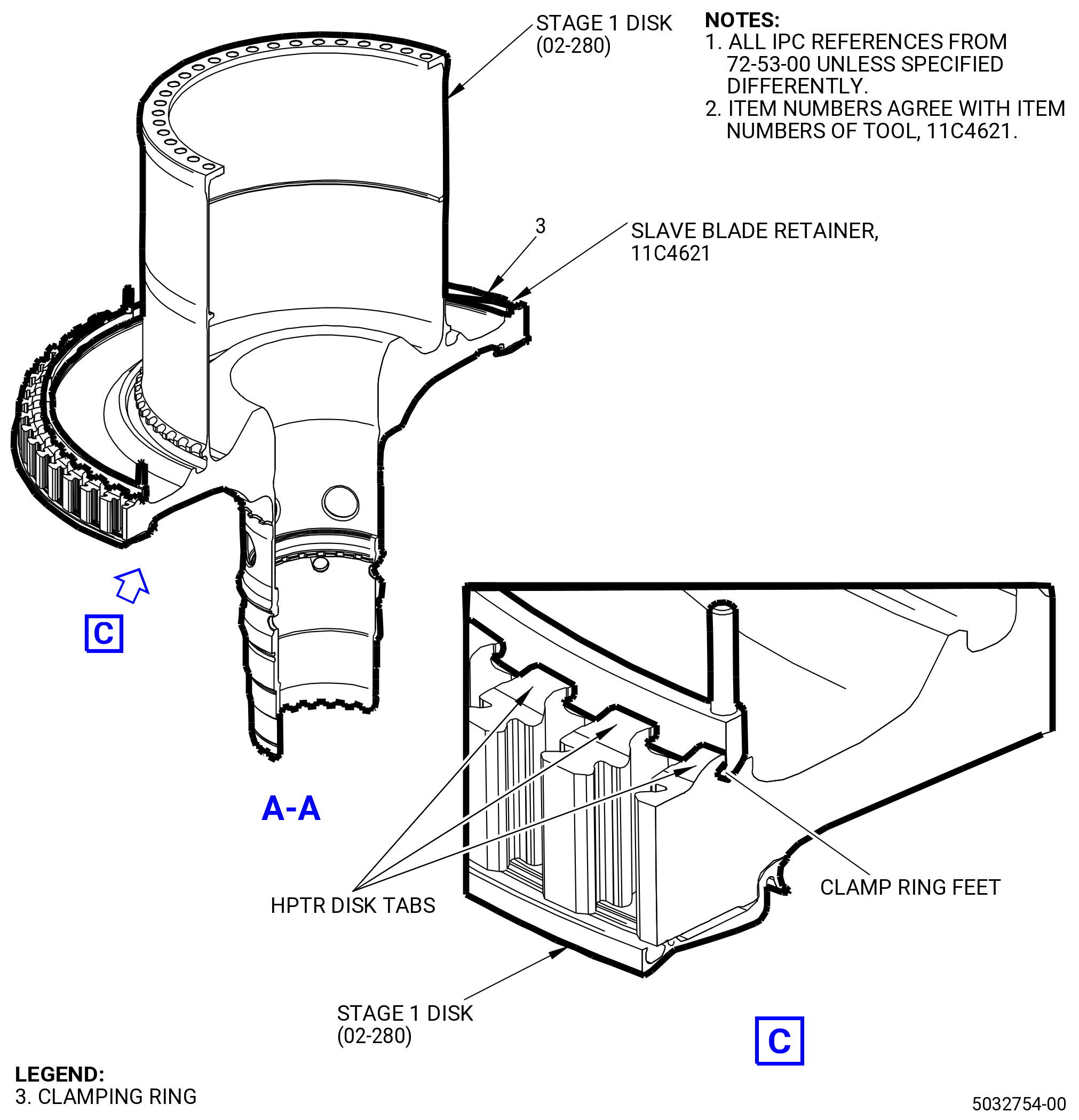
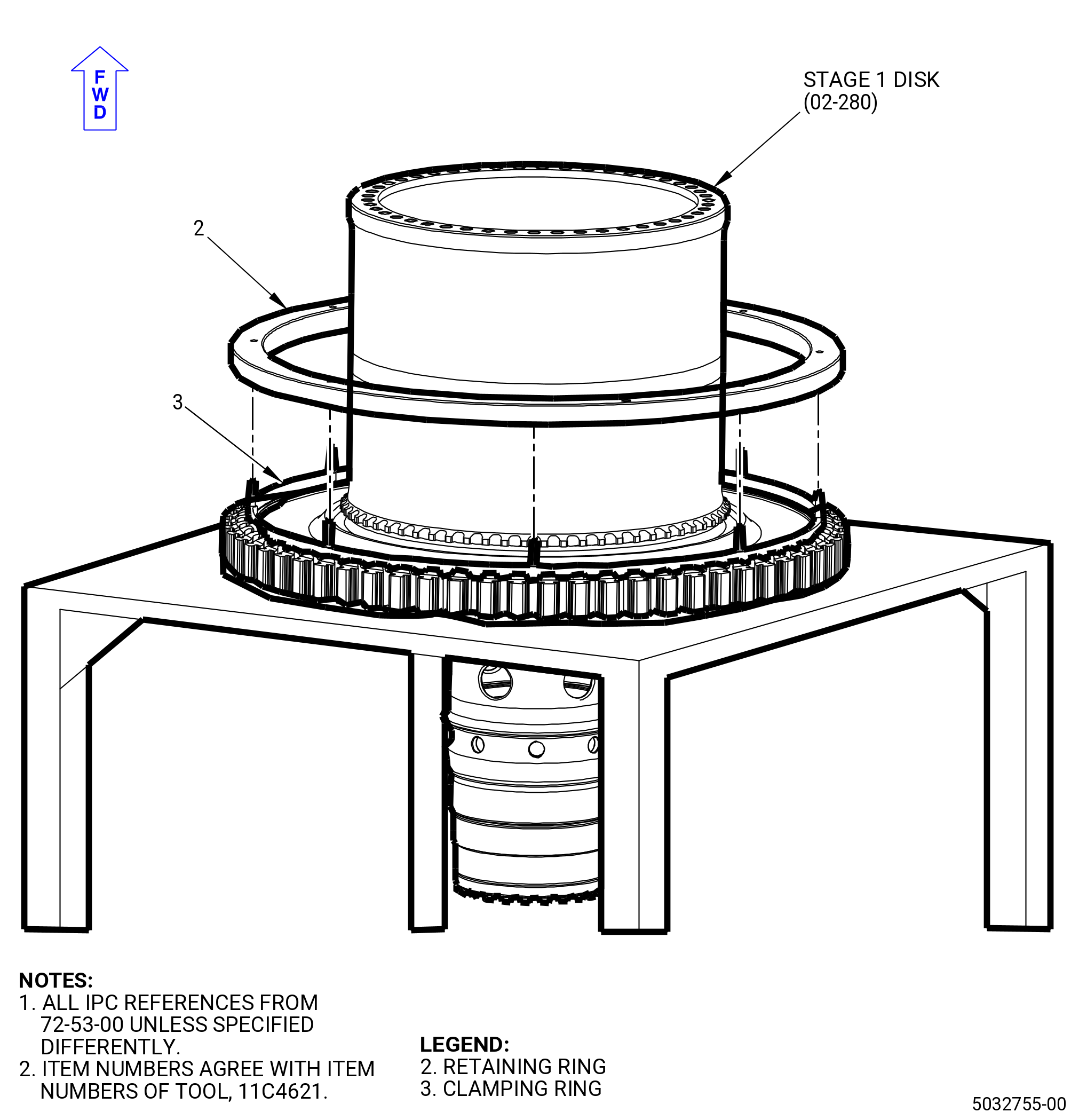
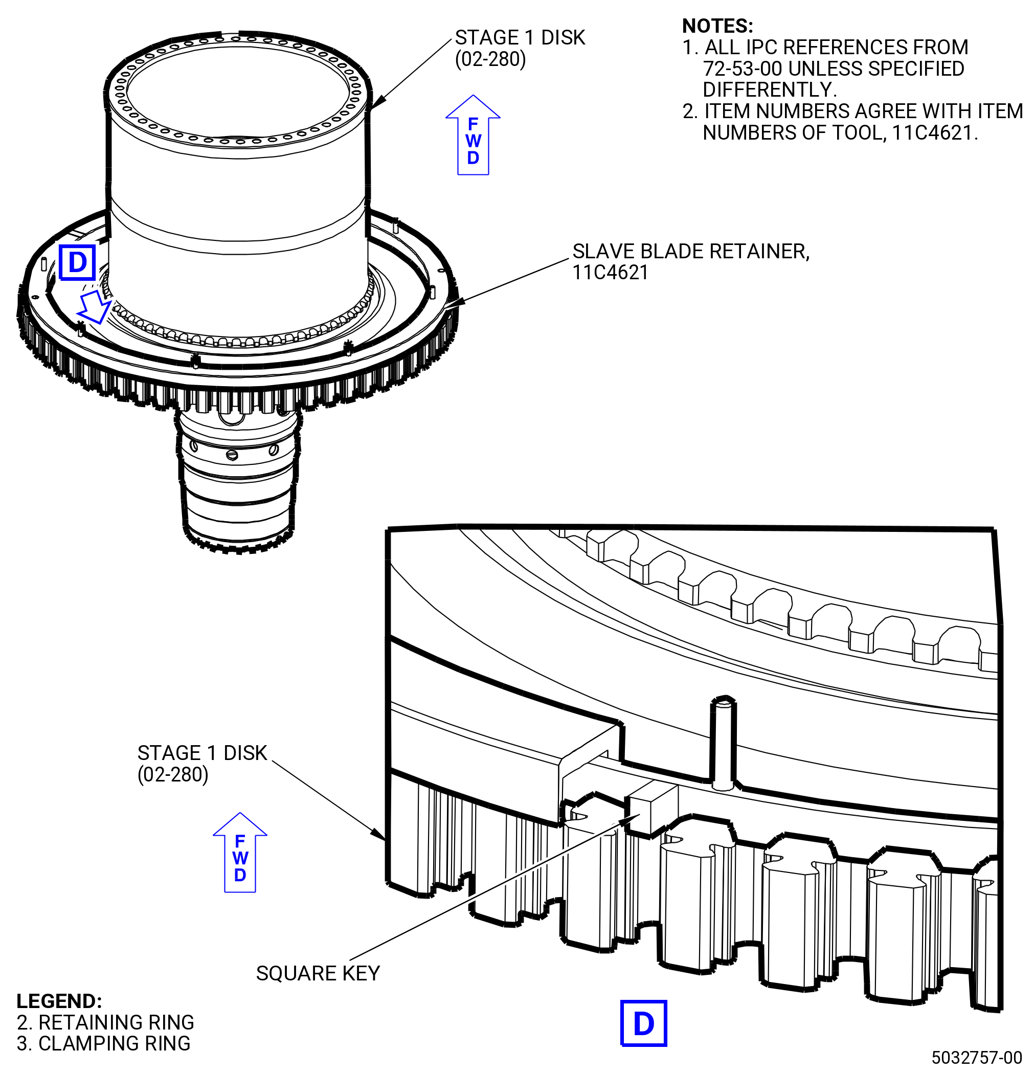
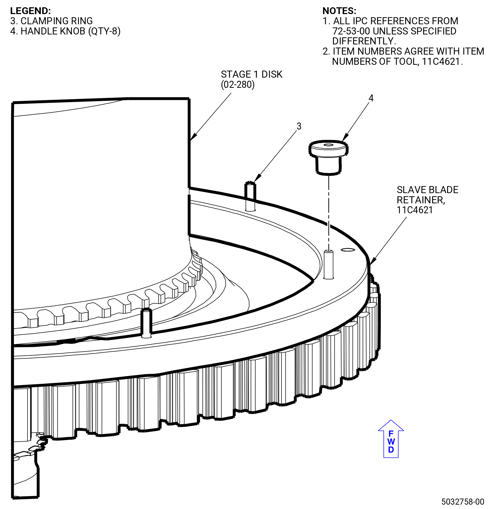
| (3) | Alternative Procedure Available. Install the 11C4621 slave blade retainer on the stage 1 disk (02-280) (SIN 150A1). Refer to Figure 1064 and do as follows: |
| (a) | If the two rings (item 2 and 3) are attached to one another, disassemble and separate them by removing the eight (8) handle knobs (item 4). |
| (b) | Put the stage 1 disk (02-280) (SIN 150A1) with the aft stage 1 blade retainer (02-180) (SIN 150BB) and stage 1 blade (02-210) (SIN 150A0) installed on an appropiate work surface aft end down. |
| (c) | Refer to the appropriate Technical Manual to install the blades. |
| (d) | Pick up the clamping ring (item 3) by the threaded rods and position over the forward shaft of the HPTR stage 1 disk. Lower the clamping ring (item 3) into the groove made for the forward blade retainer. |
| (e) | Rotate the clamping ring (item 3) in the HPTR forward blade retainer groove until the clamp feet engage the tabs of the HPTR disk. |
| (f) | Optional. Install the two eyebolts or hoist ring (not included with tool) by threading them into the retaining ring (item 2) marked “FOR TOOL LIFT”. |
| (g) | While holding the retaining ring (item 2) by the two eyebolts (hoist rings) or the edges of the retaining ring, lower over the forward shaft of the HPTR. |
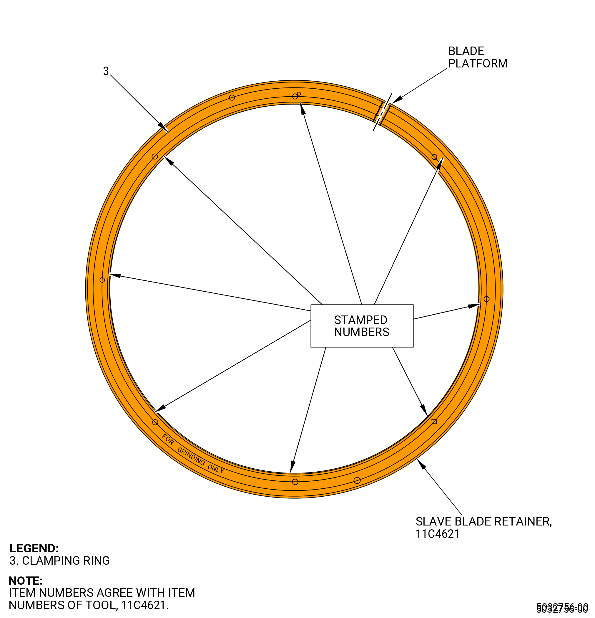
| (h) | Please note that there are matching numbers stamped next to the threaded studs of the clamping ring (item 3) and the holes of the retaining ring (item 2). Continue lowering the retaining ring (item 2) while aligning the holes in the retaining ring (item 2) with the threaded studs of the clamping ring (item 3). Be careful not to disengage the clamp feet of the clamping ring (item 3) from the HPTR disk. |
| (i) | When the retaining ring (item 2) is resting on the HPTR disk, rotate slightly back and forth, until the two square keys lock between the tabs of the HPTR disk and the “BLADE PLATFORM” marking must align with the blade platform. |
| (j) | Install the eight handle knobs (item 4) onto the clamping ring (item 3) threaded studs. Tighten them in a criss-cross pattern until tight. |
| (k) | Remove the two eyebolts (hoist rings) (if used) and store. |
| (l) | The assembly is now ready for the grinding machine. |
| Subtask 72-53-00-440-534 |
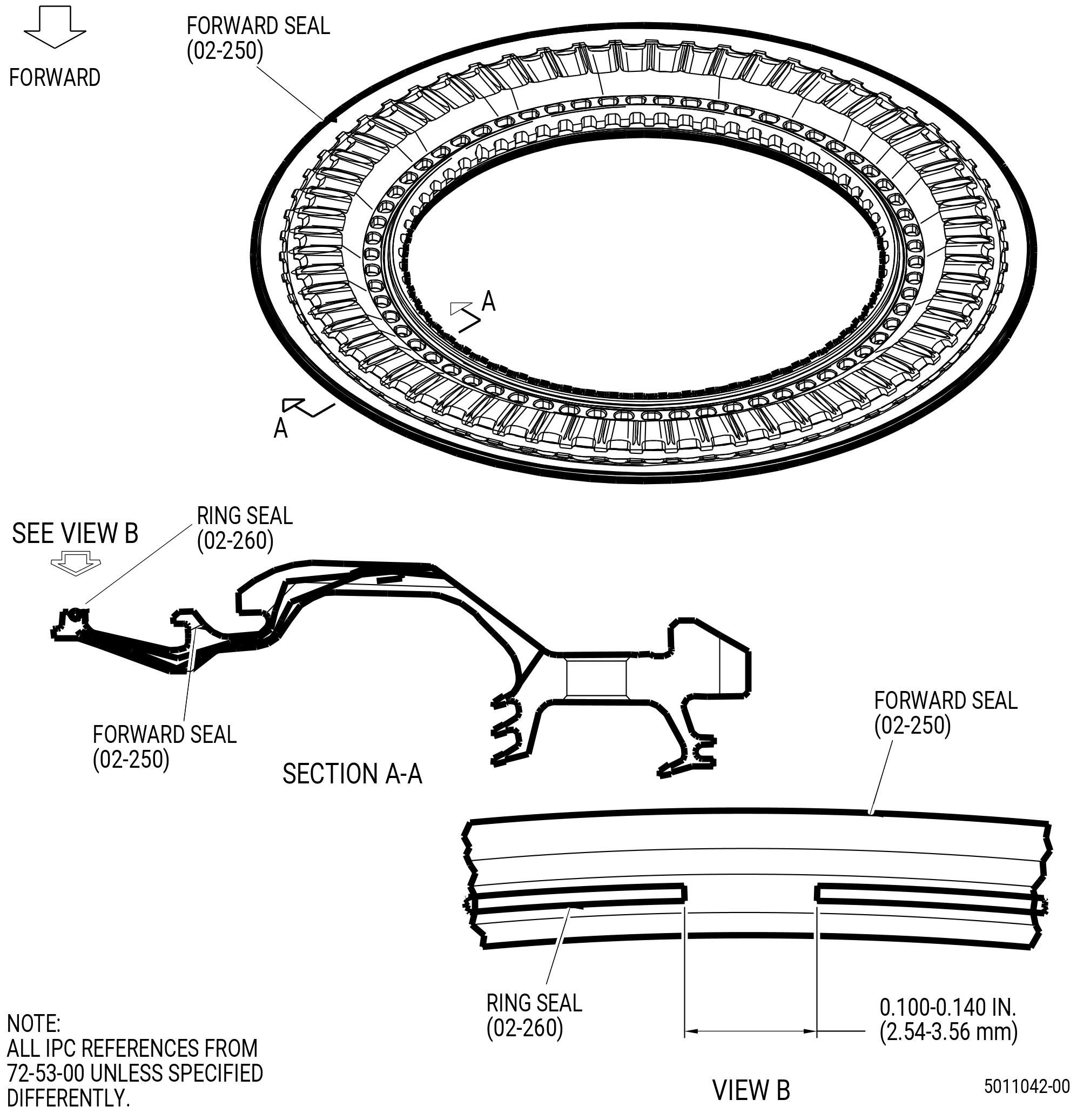
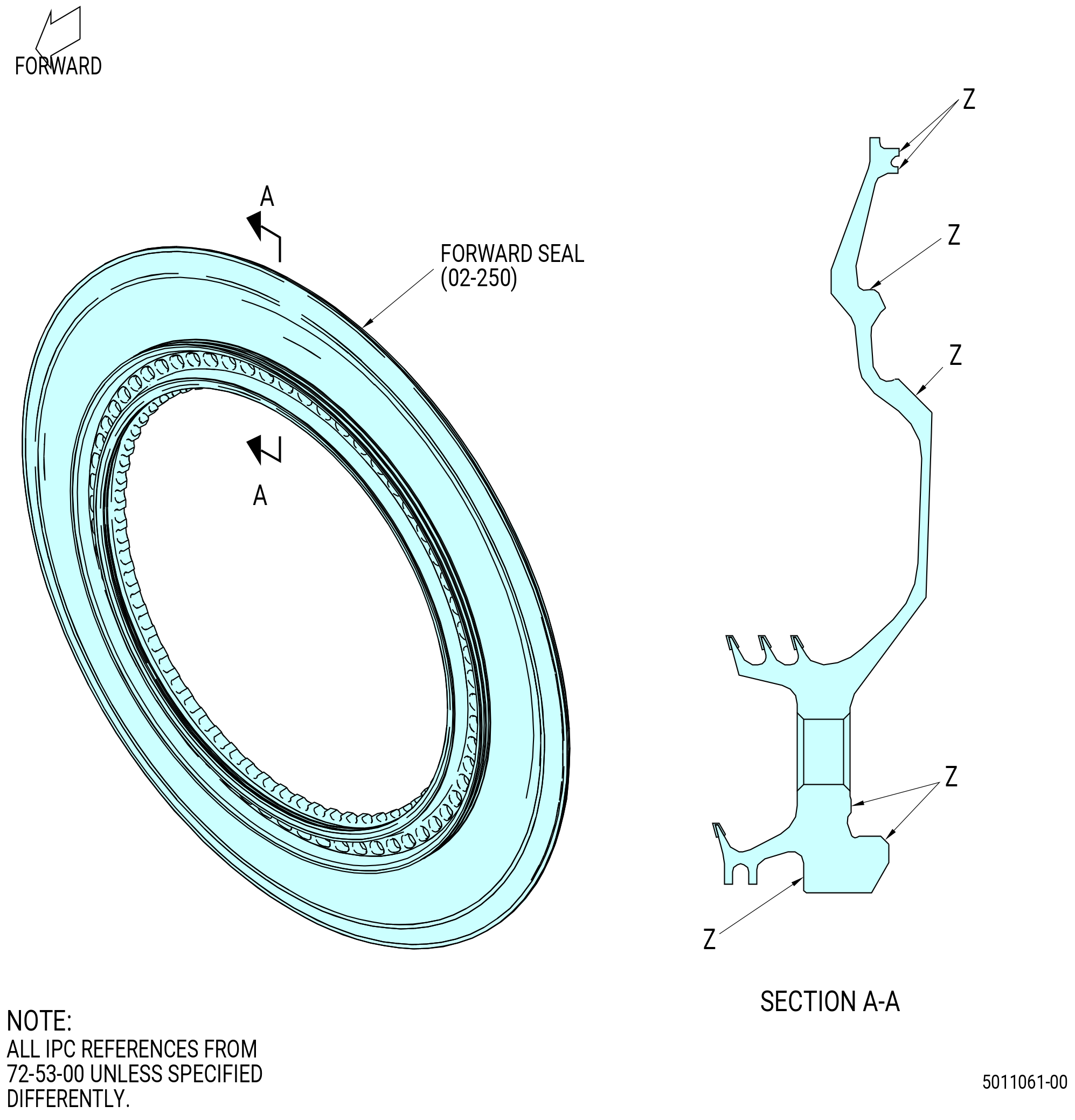
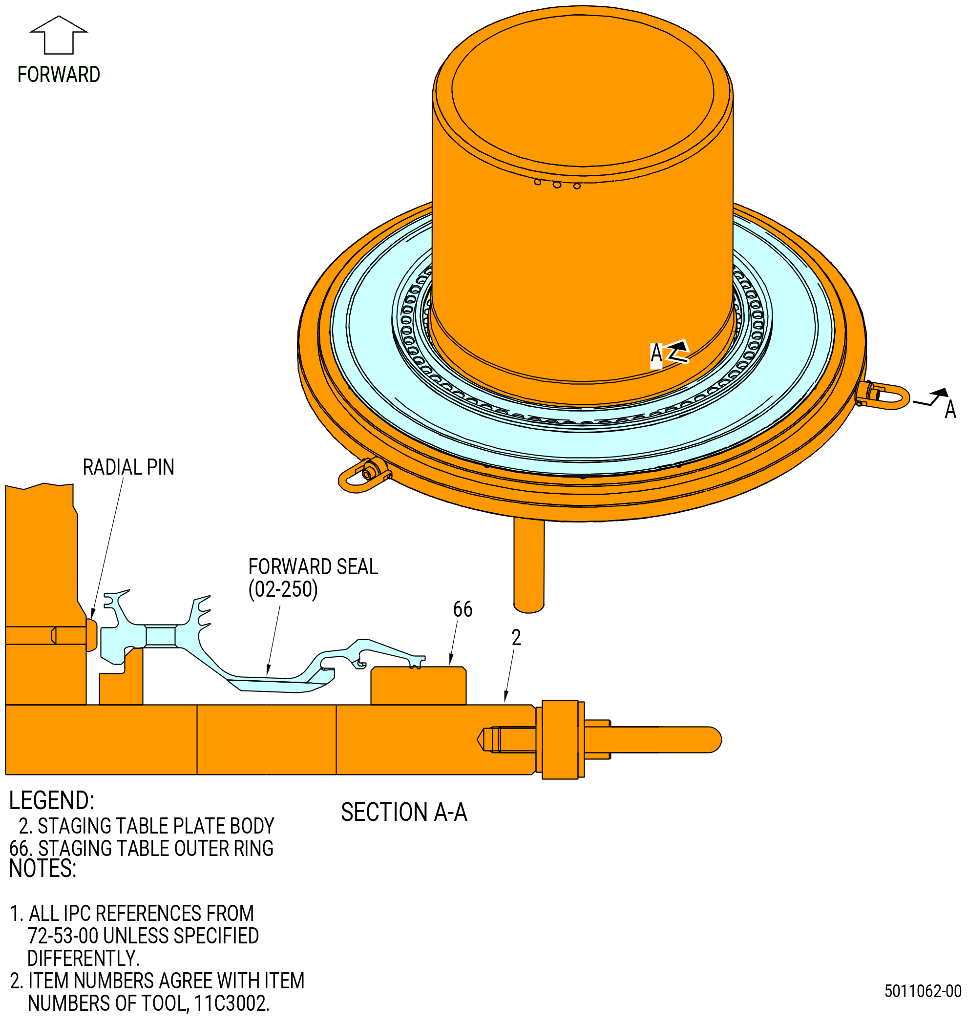
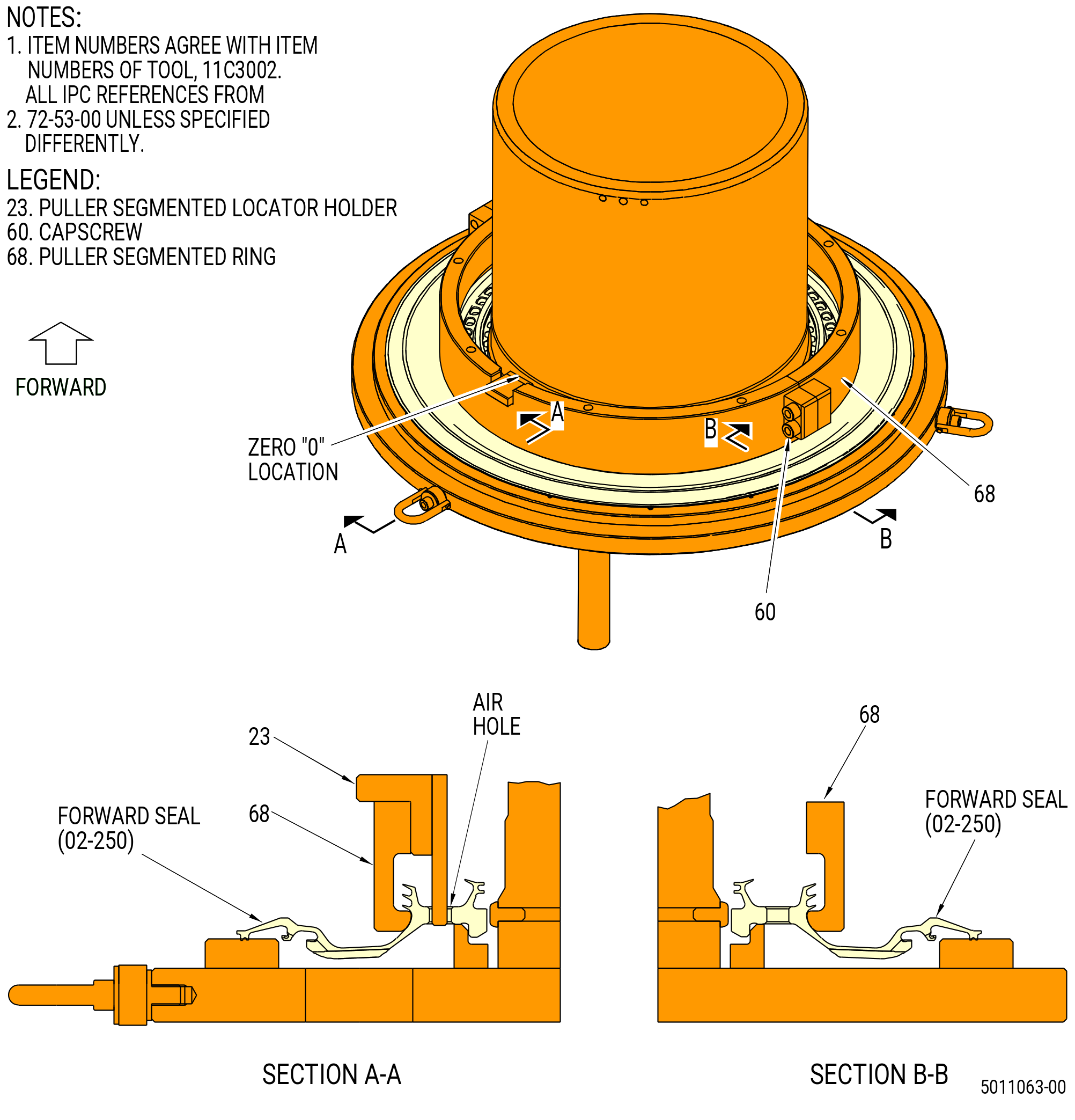
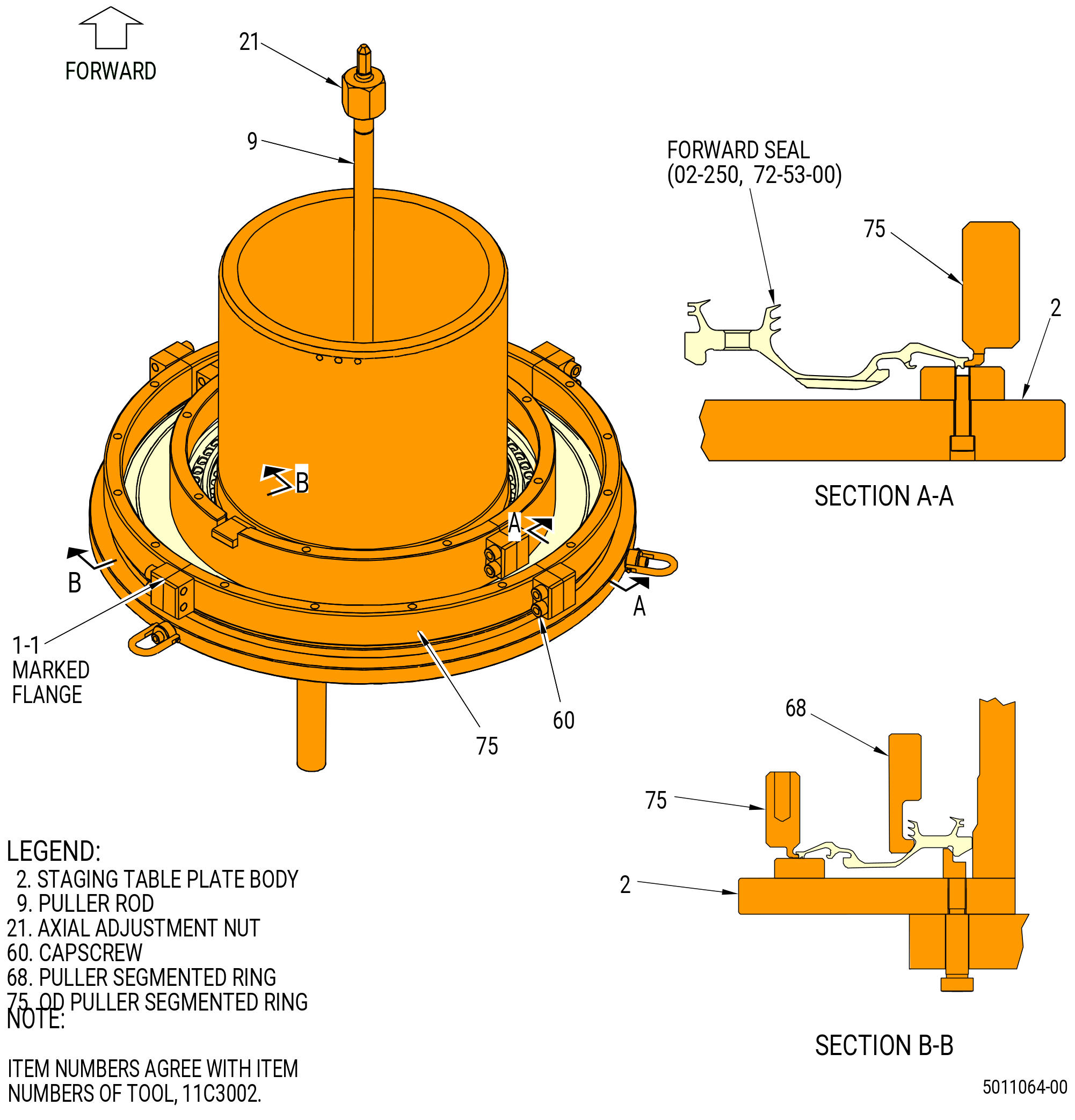
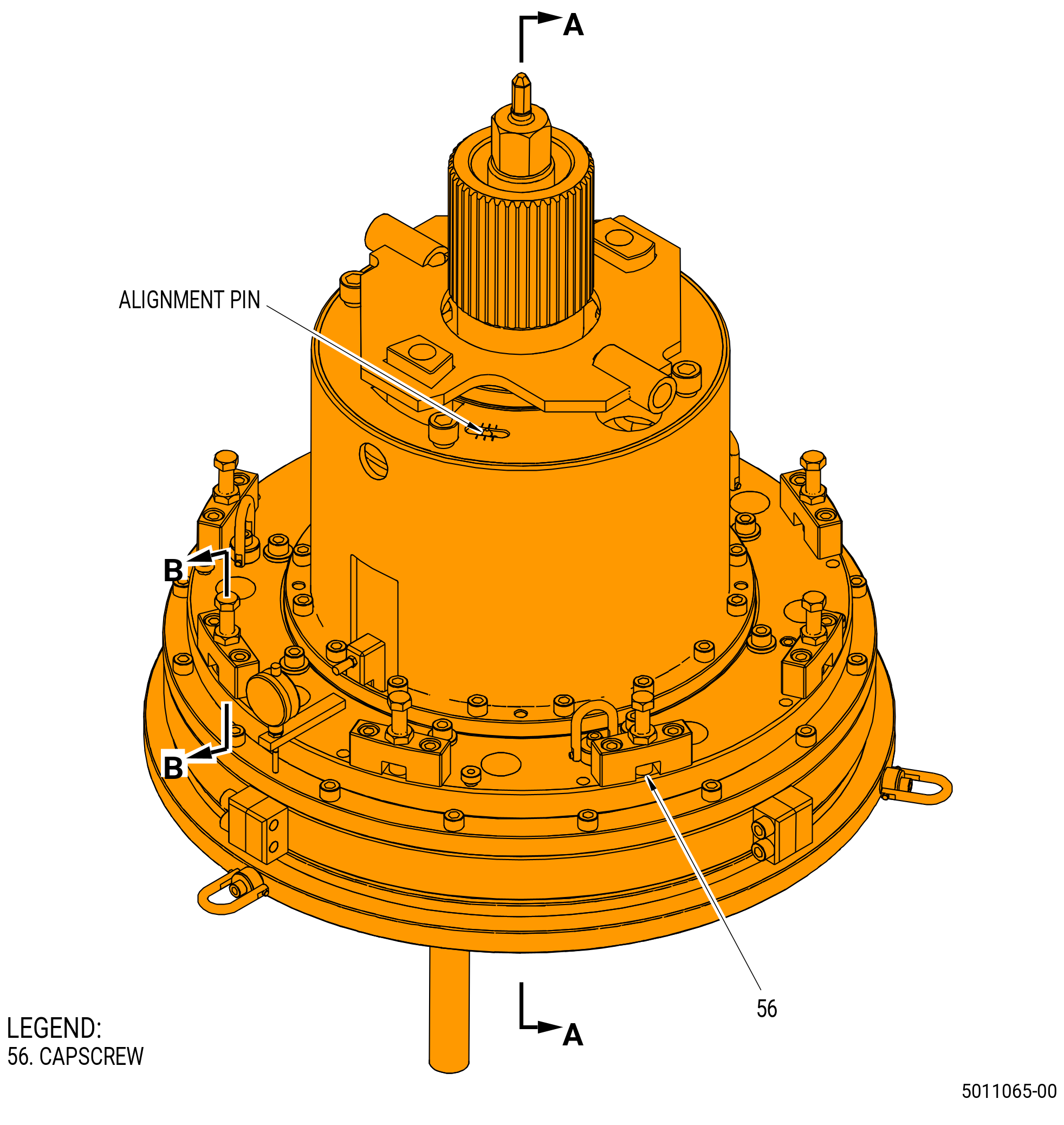
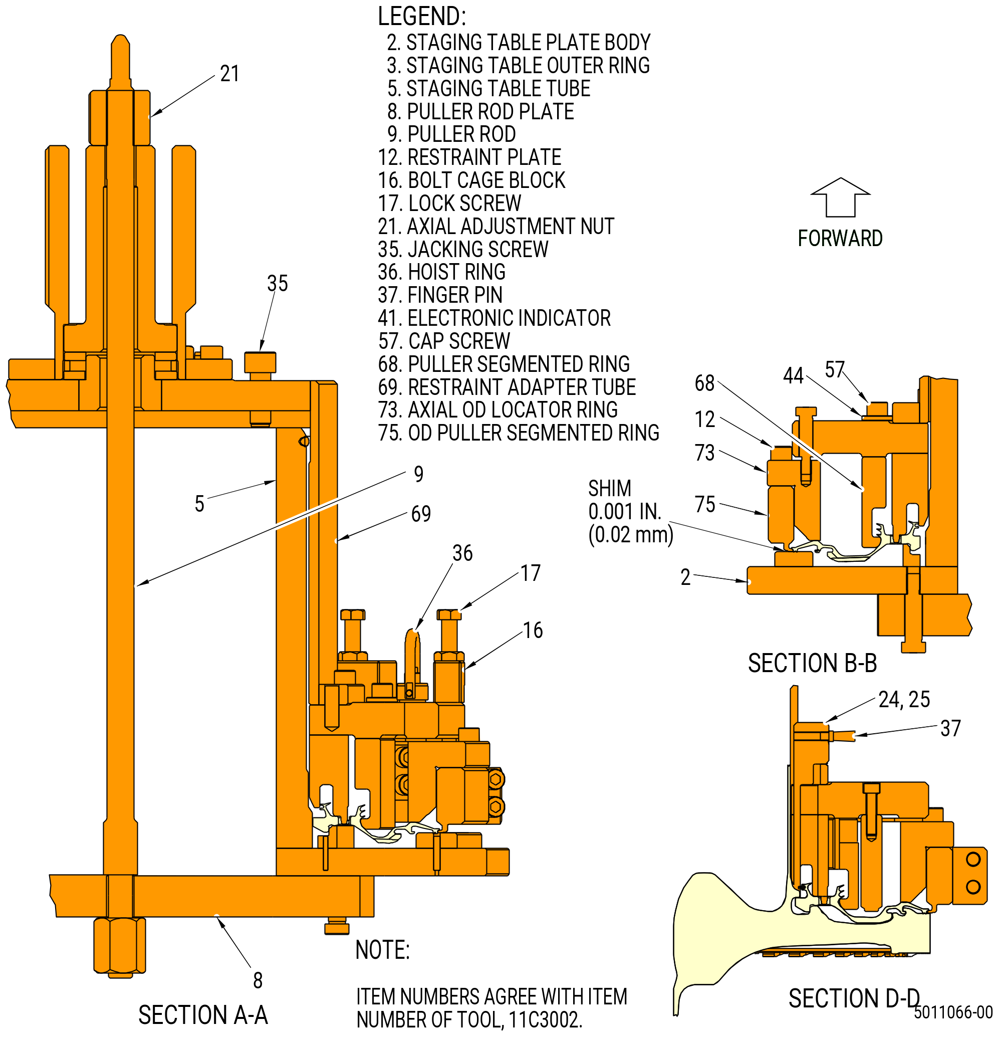
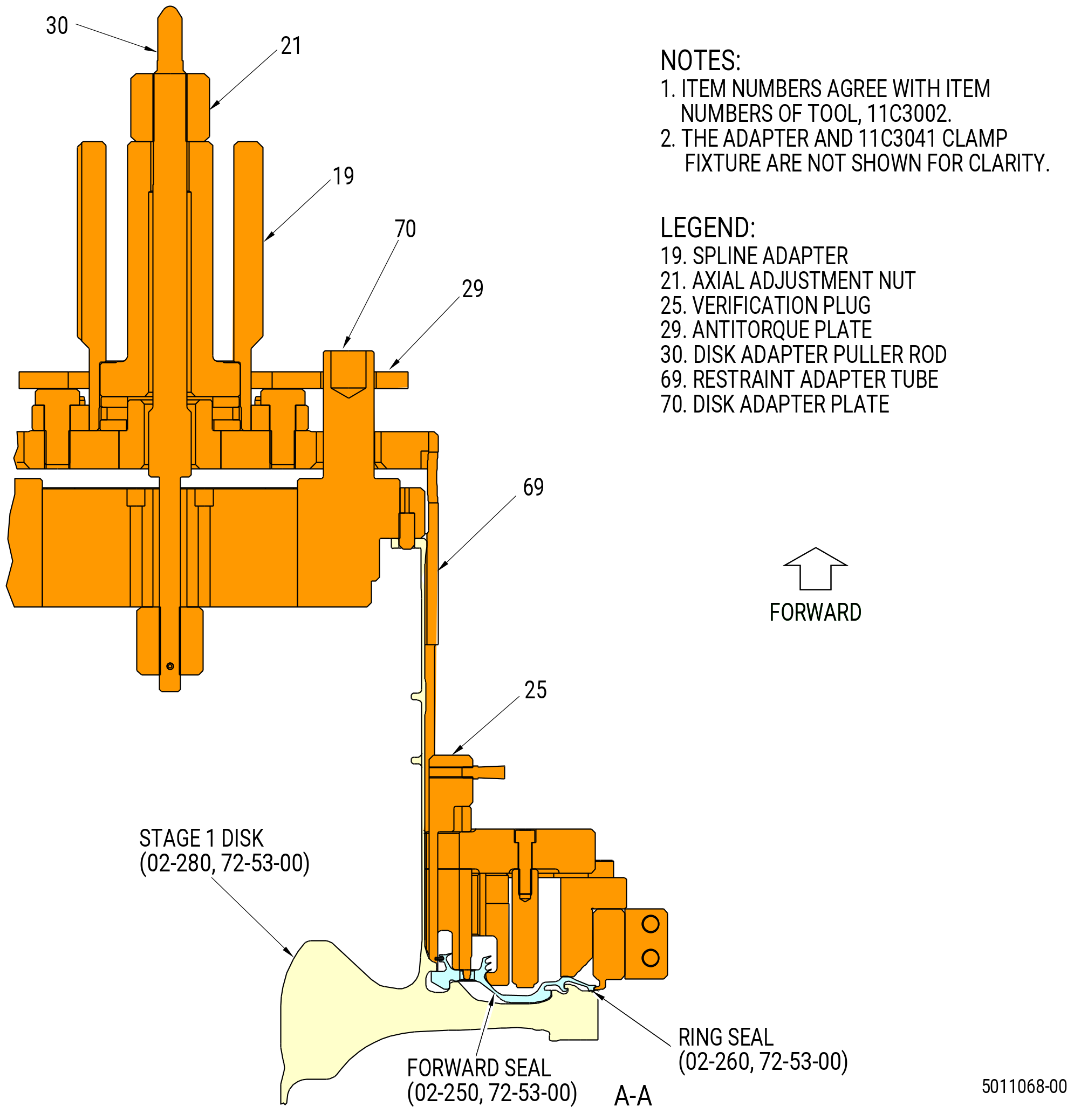
| (3).A. | Alternative Procedure. Install the forward seal (02-250) (SIN 150A3) on the HPT rotor assembly (34-021 , 72-00-02) (SIN 15000). Refer to Subtask 72-53-00-440-486 (paragraph 3.AQ) thru Subtask 72-53-00-440-503 (paragraph 3.AX). |
| Subtask 72-53-00-440-535 |
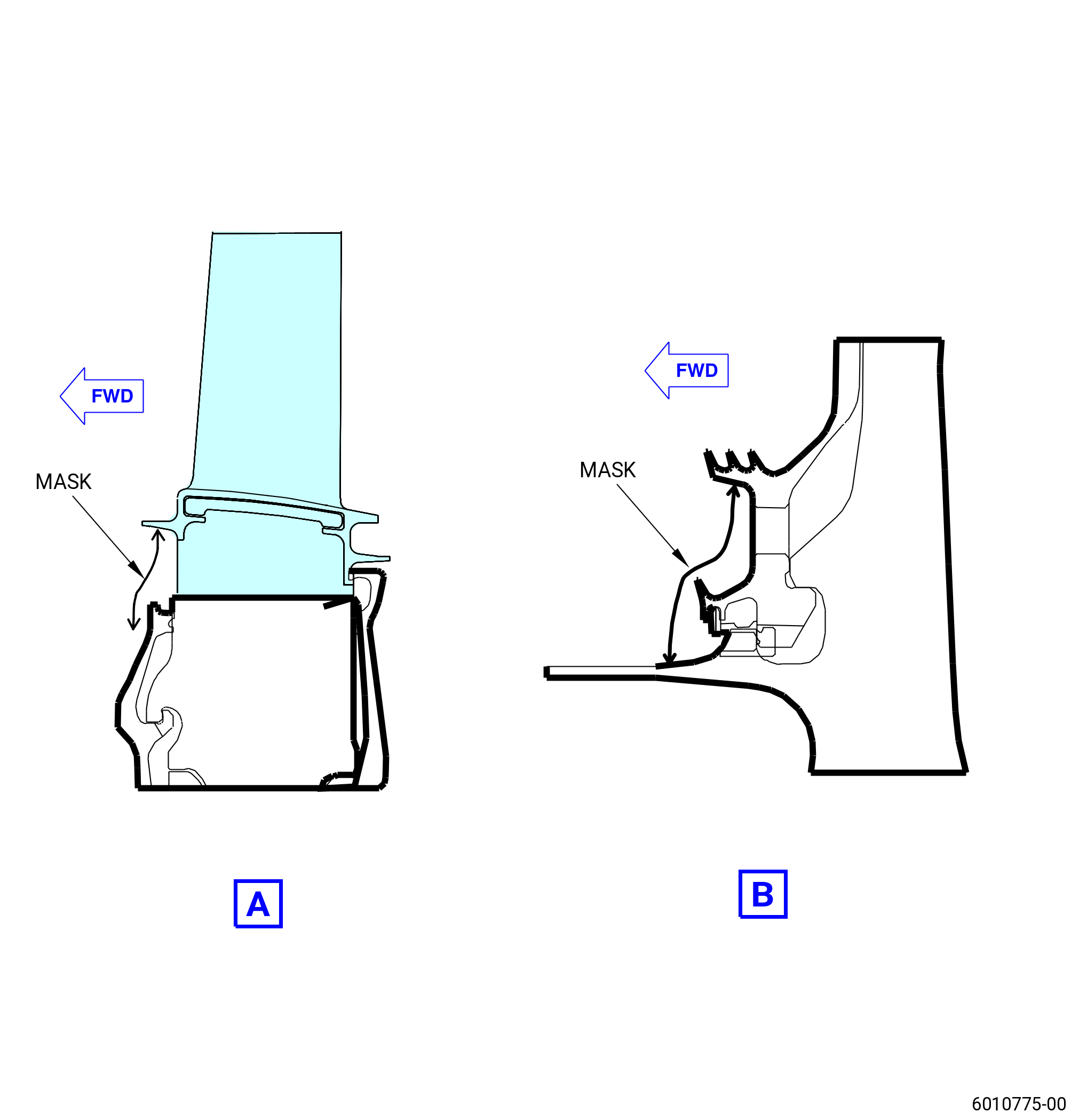
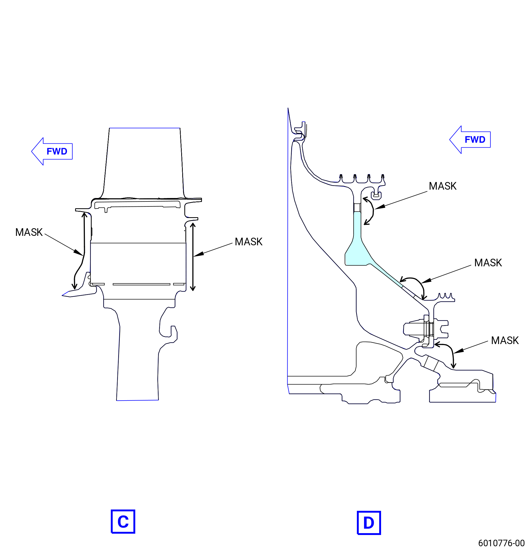
| (4) | Mask the HPT rotor components. Refer to Figure 1061: |
| (a) | Use C10-021 tape or an applicable equivalent as necessary. |
| Subtask 72-53-00-440-475 |
| (5) | Deleted. |
| Subtask 72-53-00-440-476 |
| (6) | Deleted. |
| Subtask 72-53-00-220-198 |
| (b) | Deleted. |
| Subtask 72-53-00-440-477 |
| (7) | Put the HPT rotor assembly in an approved dolly. |
| Subtask 72-53-00-220-219 |
| (8) | Do a general visual inspection of the exposed surfaces of HPT rotor stage 1 disk for nicks, dents, and scratches after the removal of tooling. Refer to TASK 72-00-53-200-802 (72-00-53, INSPECTION 001 - CONFIG 02). Refer to Figure 1066. |
| Subtask 72-53-00-440-478 |
| AI. | Grind the stage 1 blades (02-210) (SIN 150A0) and stage 2 blades (02-110) (SIN 150B0) as follows: |
| WARNING: |
|
| CAUTION: |
|
| (1) | Refer to the grind machine manufacturer's instructions for blade installation and grind procedures. |
| Subtask 72-53-00-440-526 |
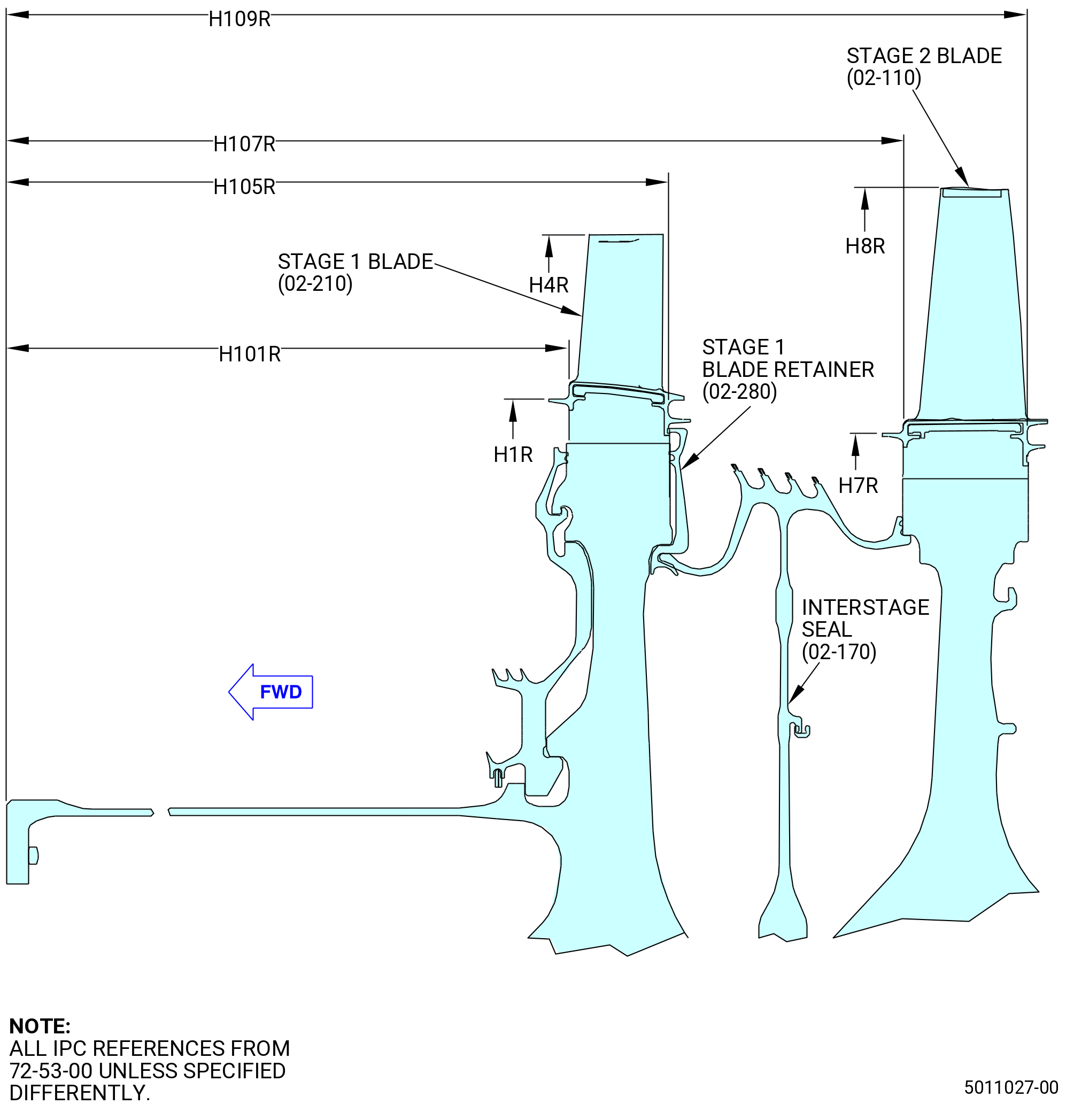
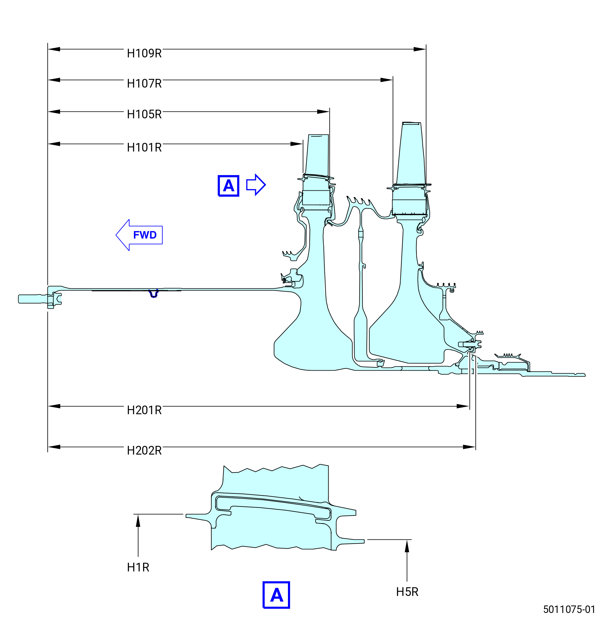
| (2) | Grind the stage 1 blades to a radius (H4R) of 15.4525-15.4555 inches (392.494-392.570 mm). |
| (3) | Grind the stage 2 blades to a target radius (H8R) of 16.0585-16.0615 inches (407.886-407.962 mm). |
| NOTE: |
|
| NOTE: |
|
| Subtask 72-53-00-220-199 |
| AJ. | Measure the H4R and H8R radii on the HPT rotor assembly (34-021 , 72-00-02) (SIN 15000). Refer to Figure 1060 and do as follows: |
| (1) | Deleted. |
| (2) | Measure radius H4R, from the center of the HPT rotor assembly (34-021 , 72-00-02) (SIN 15000) to the outer edge of the stage 1 blades (02-210) (SIN 150A0) to the outer forward angel wing of the stage 1 blades (02-210) (SIN 150A0). Refer to Figure 1060 and do as follows: |
| (a) | Measure at the outer edge of each stage 1 blade. |
| 1 | Make sure that each H4R measurement is 15.4525-15.4555 inches (392.494-392.570 mm). |
| (b) | Record the maximum radius of H4R. |
| • |
|
| (c) | Record the minimum radius of H4R. |
| • |
|
| NOTE: |
|
| (3) | Deleted. |
| (4) | Measure radius H8R, from the center of the HPT rotor assembly (34-021 , 72-00-02) (SIN 15000) to the outer edge of the stage 2 blades (02-110) (SIN 150B0). Refer to Figure 1060 and do as follows: |
| (a) | Measure at the outer edge of each stage 2 blade. |
| 1 | Make sure that each H8R measurement is 16.0585-16.0615 inches (407.886-407.962 mm). |
| NOTE: |
|
| (b) | Record the maximum radius of H8R. |
| • |
|
| (c) | Record the minimum radius of H8R. |
| • |
|
| Subtask 72-53-00-440-479 |
| AK. | Put the HPT rotor assembly (34-021 , 72-00-02) (SIN 15000) aft end up on the 11C3024 assembly/disassembly fixture as follows: |
| (1) | This procedure begins with the HPT rotor assembly in a dolly, in the horizontal position, with the balance arbor, slave race, and nut of the balance tooling installed. |
| (2) | Attach the forward lift fixture and handling arm supplied with the balance tooling to the balance arbor. Connect the handling arm to an overhead hoist. |
| (3) | Attach the aft lift fixture supplied with the balance tooling to the nut. |
| (4) | Attach the handling arm to the aft lift fixture. Connect the handling arm to an overhead hoist. |
| WARNING: |
|
| (5) | Lift the HPT rotor assembly from the dolly. |
| CAUTION: |
|
| (6) | Turn the HPT rotor assembly until it is in the vertical position, aft end up. |
| (7) | Lower the HPT rotor assembly and remove the balance arbor. Refer to the manufacturer's instructions. |
| (8) | Attach the stage 1 disk to the 11C3024 assembly/disassembly fixture. Refer to Subtask 72-53-00-440-443 (paragraph 3.F.). |
| (9) | Remove the handling arm and aft lift fixture. |
| Subtask 72-53-00-440-480 |
| AL. | Remove the stage 2 blades (02-110) (SIN 150B0) from the stage 2 disk (02-130) (SIN 150B1) as follows: |
| (1) | Remove the 11C3019 slave blade retainer from the stage 2 disk. Refer to Figure 1065 and do as follows: |
| (a) | Turn the hand knobs (item 10) opposite each other around the circumference to loosen the clamps (item 11). |
| (b) | Move the hand knobs (item 10) to put the clamps (item 11) in the DISENGAGED position as shown on the retaining ring (item 2). |
| (c) | Remove the 11C3019 slave blade retainer with the slide hammer (item 5). |
| (2) | Put number marks on the stage 2 blades related to their positions in the stage 2 disk. Start the marks with the 1-1 slot and move CW. |
| (3) | Remove the stage 2 blades from the stage 2 disk. |
| (4) | Remove any grind dust from the stage 2 blades with a dry cloth. Make sure that the position marks are not removed. |
| (5) | Put all the stage 2 blades in the 11C3015 blade container, airfoils facing down. |
| Subtask 72-53-00-440-481 |
| CAUTION: |
|
| AM. | Install the HPT rotor assembly (34-021 , 72-00-02) (SIN 15000) on the 11C3024 assembly/disassembly fixture and 11C3041 clamp fixture, forward end up as follows: |
| NOTE: |
|
| (1) | Remove the HPT rotor assembly from the 11C3024 assembly/disassembly fixture. Refer to Subtask 72-53-00-440-464 (paragraph 3.Y.(1)). |
| (2) | Remove the nuts (item 14) and washers (item 20) from the four short studs to remove the retaining ring segments (item 24) from the aft face of the forward flange of the stage 1 disk (02-280) (SIN 150A1). Refer to Figure 1006. |
| (3) | Install the balance arbor and forward lift fixture. Refer to Subtask 72-53-00-440-465 (paragraph 3.Y.(2)). |
| WARNING: |
|
| CAUTION: |
|
| (4) | Turn the HPT rotor assembly to the vertical position, aft end down. |
| (5) | Remove the handling fixture and the aft lift fixture. |
| (6) | Make sure that the bore disk protector (item 10) of the 11C3024 assembly/disassembly fixture is installed. Refer to Figure 1005. |
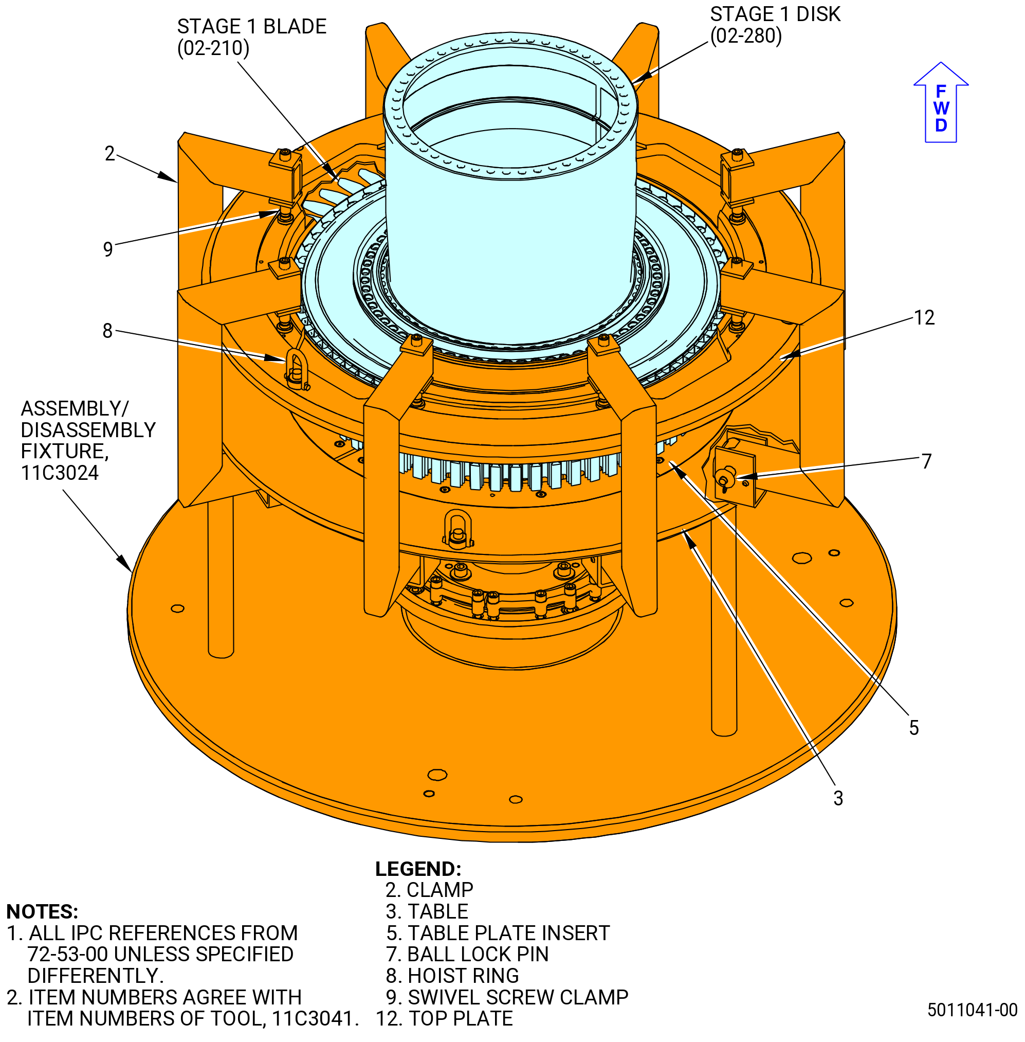
| (7) | Install the table plate insert (item 5) of the 11C3041 clamp fixture on the 11C3024 assembly/disassembly fixture. Refer to Figure 1067 and do as follows: |
| NOTE: |
|
| (a) | Attach a three-legged sling to the hoist rings (item 8) on the base plate (item 2) of the 11C3041 clamp fixture. |
| (b) | Lift the 11C3041 clamp fixture with an overhead hoist and install it on the 11C3024 assembly/disassembly fixture. |
| Subtask 72-53-00-440-482 |
| WARNING: |
|
| (8) | Lower the HPT rotor assembly to the 11C3024 assembly/disassembly fixture so that the aft face of the stage 2 disk (02-130) (SIN 150B1) is against the plate table insert (item 5) of the 11C3041 clamp fixture. |
| Subtask 72-53-00-440-483 |
| AN. | Remove the stage 1 blades (02-210) (SIN 150A0) from the stage 1 disk (02-280) (SIN 150A1) as follows: |
| NOTE: |
|
| (1) | Remove the balance arbor from the stage 1 disk. Refer to Subtask 72-53-00-440-475 (paragraph (3.AG.(2)). |
| (2) | Remove the 11C4621 slave blade retainer from the stage 1 disk. Refer to Figure 1063 and do as follows: |
| (a) | Loosen all eight handle knobs (item 4) and remove/store. Refer to Figure 1064. |
| (b) | With the threaded stud of the clamping ring (item 3), rotate the clamping ring (item 3) in the HPTR groove until the clamp feet are clear of the HPTR disk tabs. Refer to Figure 1064. |
| (c) | Remove the clamping ring (item 3) by lifting upward. Refer to Figure 1064. |
| (d) | Assemble all loose components and store. |
| (3) | Put number marks on the stage 1 blades related to their positions in the stage 1 disk. Start the marks with the 1-1 slot and move CCW, FLA. |
| (4) | Remove the stage 1 blades from the stage 1 disk. |
| CAUTION: |
|
| (5) | Remove any grind dust from the stage 1 blades with a dry cloth. Make sure that the position marks are not removed. |
| (6) | Put all the stage 1 blades in the 11C3015 blade container, airfoils facing down. |
| Subtask 72-53-00-440-484 |
| AO. | Machine tip notches in the stage 1 blades (02-210) (SIN 150A0) and stage 2 blades (02-110) (SIN 150B0) as follows: |
| NOTE: |
|
| (1) | Machine tip notches in the No. 1 and No. 32 stage 2 blades as follows: |
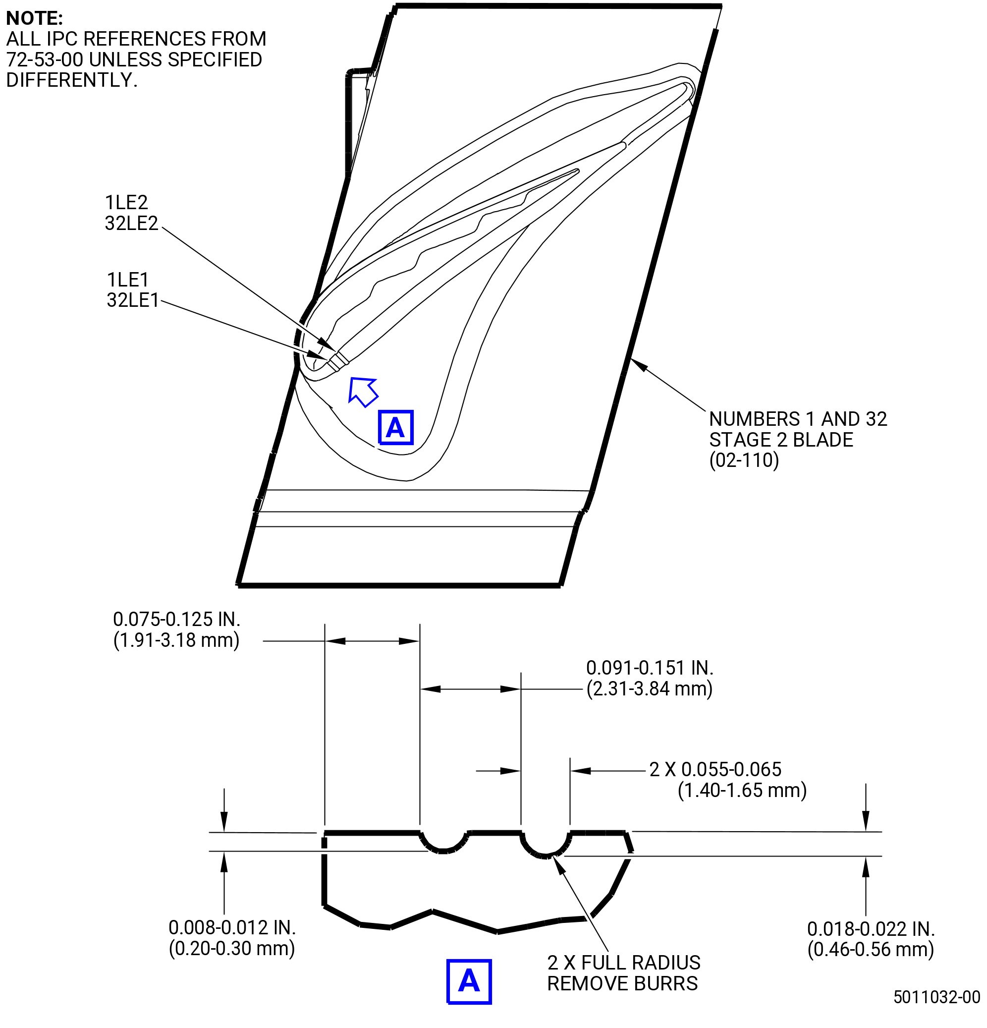
| (a) | For position and dimensions of the tip notches for the stage 2 blades, refer to Figure 1068. |
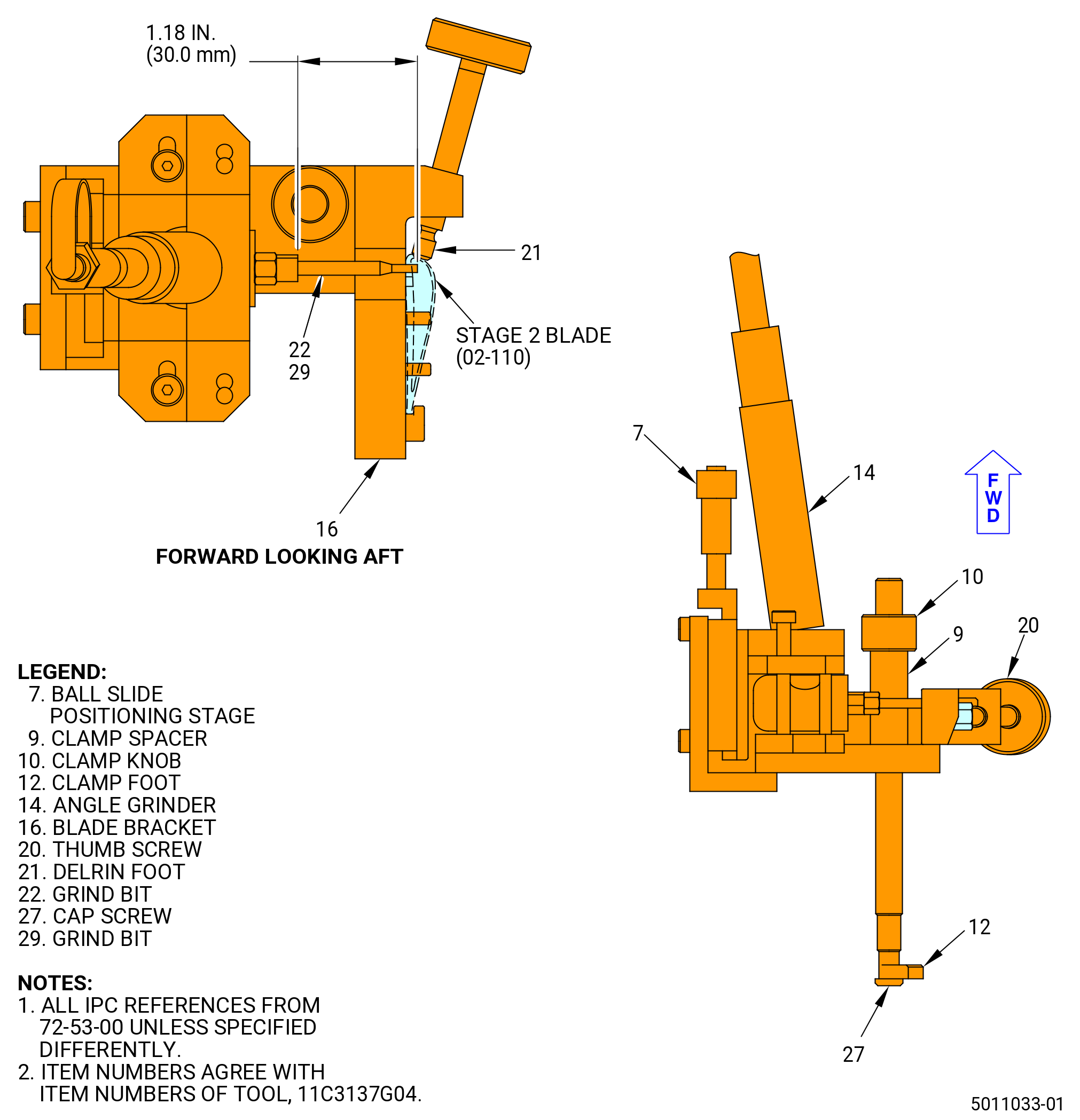
| (b) | Machine the two leading edge notches on the concave side of the stage 2 blades with the 11C3137G04 fixture. Refer to Figure 1068. |
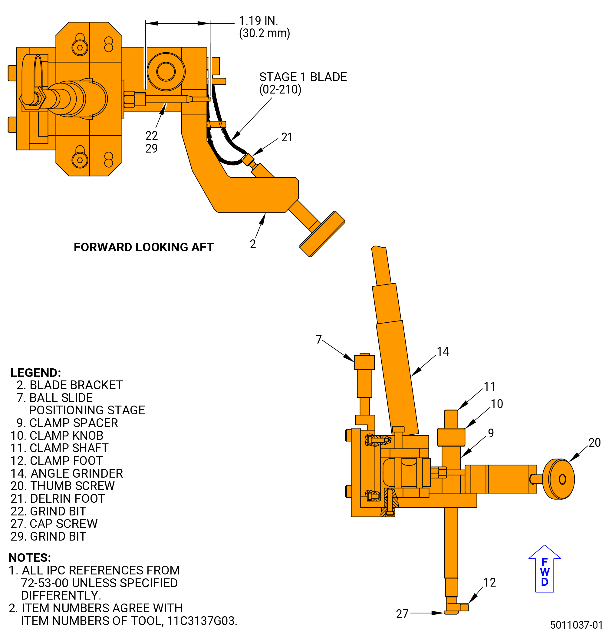
| 1 | Insert the grind bit (item 22) into the collet located at the front of the angle grinder (item 14). Extend the grind bit to 1.19 inches (30.2 mm) and tighten the chuck. |
| 2 | Install the 11C3137G04 fixture on the HPT stage 2 rotor blade, turn the thumb screw (item 20) CCW, and fully retract it. This will let the 11C3137G04 fixture to be installed on the HPT stage 2 rotor blade. |
| 3 | Turn the clamp knob (item 10) CCW to fully retract the clamping devices (item 9, 10, 12, 13, and 27). |
| 4 | Put the 11C3137G04 fixture on the top of the HPT stage 2 rotor blade to let it rest on the blade bracket (item 16) straight pin. |
| 5 | Put the 11C3137G04 fixture until the vertical trailing edge of the HPT stage 2 rotor blade is against the blade bracket (item 16) straight pin. The blade bracket (item 16) straight pin is opposite to the thumb screw (item 20) on the blade bracket (item 16). |
| 6 | Turn the thumb screw (item 20) CW until the delrin foot (item 21) safely secures the 11C3137G04 fixture to the leading edge of the HPT stage 2 rotor blade. |
| 7 | Make sure that the 11C3137G04 fixture continues on the blade bracket (item 16) straight pin. |
| 8 | Turn the clamp knob (item 10) CW until the clamp foot (item 12) tightly secures the 11C3137G04 fixture into place on the HPT stage 2 rotor blade. |
| 9 | Put the grind bit (item 22) closest to the blade bracket (item 16) straight pin and to the trailing edge of the HPT stage 2 rotor blade. |
| WARNING: |
|
| 10 | Use shop supplied air to attach a female quick disconnect hose connector to the male quick disconnect hose connector on the top of the angle grinder (item 14). |
| 11 | Turn the micrometer thimble on the ball slide positioning stage (item 7) CCW to lower the grind bit (item 22) until it barely touches the HPT stage 2 rotor blade. |
| 12 | For the 0.01 inch (0.25 mm) notch, turn the micrometer thimble on the ball slide positioning stage (item 7) CCW to lower the grind bit (item 22), 0.01 inch (0.25 mm) past the initial point of contact with the HPT rotor blade stage 2 to create the wear notch. |
| 13 | Turn the ball slide positioning stage (item 7) CW to lift the grind bit (item 22) to its original starting position and disconnect the hose from the angle grinder (item 14). |
| 14 | Remove the grind bit (item 22) with two wrenches to loosen the angle grinder (item 14). Put one wrench on the collet flats of the angle grinder (item 14) and the other wrench on the flats of the grinder rotor/chuck body assembly. |
| 15 | Insert the grind bit (item 29) into the collet located at the front of the angle grinder (item 14). Extend the grind bit (item 29) to 1.19 inches (30.2 mm) and tighten the angle grinder (item 14). |
| 16 | Put the grind bit (item 29) closest to the leading edge of the HPT stage 2 rotor blade. |
| WARNING: |
|
| 17 | Use shop supplied air to attach a female quick disconnect hose connector to the male quick disconnect hose connector on the top of the angle grinder (item 14). |
| 18 | Turn the micrometer thimble on the ball slide positioning stage (item 7) CCW to lower the grind bit (item 29) until it barely touches the HPT stage 2 rotor blade. |
| 19 | For the 0.02 inch (0.51 mm) notch, turn the micrometer thimble on the ball slide positioning stage (item 7) CCW to lower the grind bit (item 22) 0.02 inch (0.51 mm) past the initial point of contact with the HPT stage 2 rotor blade to create the wear notch. |
| 20 | Turn the ball slide positioning stage (item 7) CW to lift the grind bit (item 29) to its original starting position and disconnect the hose air supply. |
| 21 | To remove the 11C3137G04 fixture turn the clamp knob (item 10) CCW until the clamp foot (item 12) is no longer in contact with the rotor assembly and remove the 11C3137G04 fixture from the HPT stage 2 rotor blade. |
| (2) | Machine tip notches in the No. 1 and No. 32 stage 1 blades as follows: |
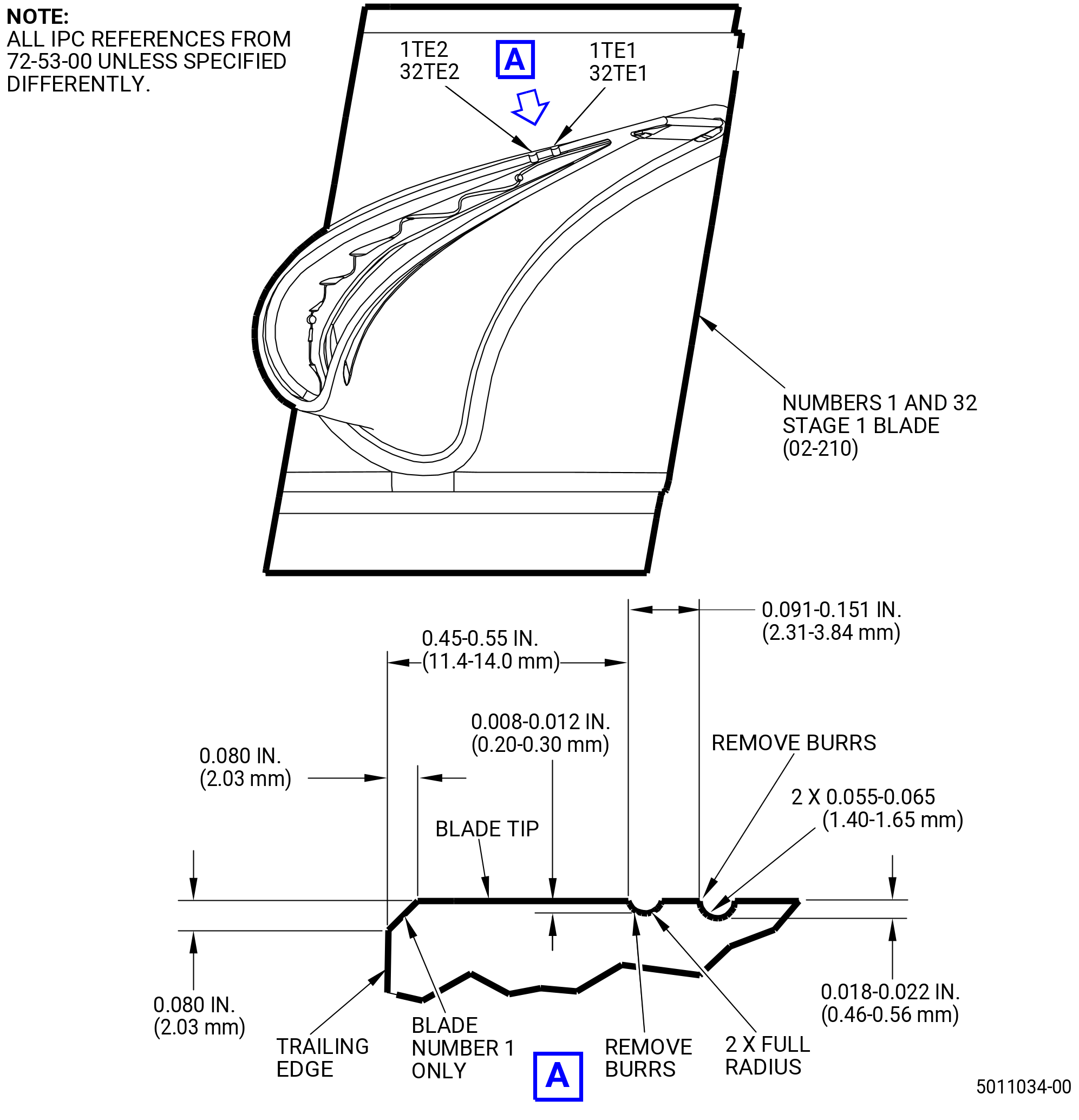
| (a) | For position and dimensions of the tip notches for the stage 1 blades, refer to Figure 1069. |
| (b) | Machine the two trailing edge notches on the convex side of the stage 1 blades with the 11C3137G03 fixture. Refer to Figure 1069. |
| 1 | Insert the grind bit (item 22) into the collet located at the front of the angle grinder (item 14). Extend the grind bit to 1.19 inches (30.2 mm) and tighten the chuck. |
| 2 | Install the 11C3137G03 fixture on the HPT stage 1 rotor blade, turn the thumb screw (item 20) CCW, and fully retract it. This will let the 11C3137G03 fixture to be installed on the HPT stage 1 rotor blade. |
| 3 | Turn the clamp knob (item 10) CCW to fully retract the clamping devices (item 9, 10, 11, 12, and 27). |
| 4 | Put the 11C3137G03 fixture on the top of the HPT stage 1 rotor blade to let it rest on the blade bracket (item 2) straight pin. |
| 5 | Put the 11C3137G03 fixture until the vertical trailing edge of the HPT stage 1 rotor blade is against the blade bracket (item 2) straight pin. The blade bracket (item 2) straight pin is opposite to the thumb screw (item 20) on the blade bracket (item 2). |
| 6 | Turn the thumb screw (item 20) CW until the delrin foot (item 21) safely attaches the 11C3137G03 fixture to the leading edge of the HPT stage 1 rotor blade. |
| 7 | Make sure that the 11C3137G03 fixture continues on the blade bracket (item 2) straight pin. |
| 8 | Turn the clamp knob (item 10) CW until the clamp foot (item 12) tightly secures the 11C3137G03 fixture into place on the HPT stage 1 rotor blade. |
| 9 | Put the grind bit (item 22) closest to the blade bracket (item 2) straight pin and to the trailing edge of the HPT stage 1 rotor blade. |
| WARNING: |
|
| 10 | Use shop supplied air to attach a female quick disconnect hose connector to the male quick disconnect hose connector on the top of the angle grinder (item 14). |
| 11 | Turn the micrometer thimble on the ball slide positioning stage (item 7) CCW to lower the grind bit (item 22) until it barely touches the HPT stage 1 rotor blade. |
| 12 | For the 0.01 inch (0.25 mm) notch, turn the micrometer thimble on the ball slide positioning stage (item 7) CCW to lower the grind bit (item 22), 0.01 inch (0.25 mm) past the initial point of contact with the HPT rotor blade stage 1 to create the wear notch. |
| 13 | Turn the ball slide positioning stage (item 7) CW to raise the grind bit (item 22) to its original starting position and disconnect the hose from the angle grinder (item 14). |
| 14 | Remove the grind bit (item 22) by using two wrenches to loosen the angle grinder (item 14). Put one wrench on the collet flats of the angle grinder (item 14) and the other wrench on the flats of the grinder rotor/chuck body assembly. |
| 15 | Insert the grind bit (item 29) into the collet located at the front of the angle grinder (item 14). Extend the grind bit (item 29) to 1.19 inches (30.2 mm) and tighten the angle grinder (item 14). |
| 16 | Put the grind bit (item 29) closest to the leading edge of the HPT stage 1 rotor blade. |
| WARNING: |
|
| 17 | Use shop supplied air to attach a female quick disconnect hose connector to the male quick disconnect hose connector on the top of the angle grinder (item 14). |
| 18 | Turn the micrometer thimble on the ball slide positioning stage (item 7) CCW to lower the grind bit (item 29) until it barely touches the HPT stage 1 rotor blade. |
| 19 | For the 0.02 inch (0.51 mm) notch, turn the micrometer thimble on the ball slide positioning stage (item 7) CCW to lower the grind bit (item 22) 0.02 inch (0.51 mm) past the initial point of contact with the HPT stage 1 rotor blade to create the wear notch. |
| 20 | Turn the ball slide positioning stage (item 7) CW to raise the grind bit (item 29) to its original starting position and disconnect the hose air supply. |
| 21 | To remove the 11C3137G03 fixture turn the clamp knob (item 10) CCW until the clamp foot (item 12) is no longer in contact with the rotor assembly and remove the 11C3137G03 fixture from the HPT stage 1 rotor blade. |
| WARNING: |
|
| (3) | Machine a 45 degree chamfer in the trailing edge of the No. 1 stage 1 blade. Refer to Figure 1069 for the location and dimensions of the 45 degree chamfer. |
| Subtask 72-53-00-220-200 |
| (4) | Measure the stage 2 blade (02-110) (SIN 150B0) notches as follows: |
| (a) | Measure the depth of the notches of the No. 1 position blade. Refer to Figure 1068. |
| (b) | Make a record of them as 1LE1 and 1LE2 on the Record Sheet. Refer to Figure 1070. |
| (c) | Measure the depth of the notches of the No. 32 position blade. Refer to Figure 1068. |
| (d) | Make a record of them as 32LE1 and 32LE2 on the Record Sheet. Refer to Figure 1070. |
| Subtask 72-53-00-220-201 |
| (5) | Measure the stage 1 blade (02-210) (SIN 150A0) notches as follows: |
| (a) | Measure the depth of the notches of the No. 1 position blade. Refer to Figure 1069. |
| (b) | Make a record of them as 1TE1 and 1TE2 on the Record Sheet. Refer to Figure 1070. |
| (c) | Measure the depth of the notches of the No. 32 position blade. Refer to Figure 1069. |
| (d) | Make a record of them as 32TE1 and 32TE2 on the Record Sheet. Refer to Figure 1070. |
| Subtask 72-53-00-440-485 |
| AP. | Install the stage 1 blades (02-210) (SIN 150A0) and the stage 1 dampers (02-220) (SIN 150AB) into the stage 1 disk (02-280) (SIN 150A1) as follows: |
| NOTE: |
|
| (1) | Record the serial numbers of the stage 1 blades in their related positions in the stage 1 disk on the Record Sheet. Refer to Figure 1065. |
| WARNING: |
|
| NOTE: |
|
| (2) | Apply C01-050 rubber cement to the stage 1 damper area of the stage 1 blade. Refer to Figure 1072. |
| (3) | Install a new stage 1 damper into the concave side of each stage 1 blade platform. Do not use the old dampers again. |
| NOTE: |
|
| CAUTION: |
|
| (4) | Install the first stage 1 blade in the 1-1 dovetail slot of the stage 1 disk. |
| (5) | Make sure that the leading edge of the stage 1 blade points forward. |
| (6) | Continue this procedure to install the remaining stage 1 blades. |
| (7) | To install the last stage 1 blade, fan the blades out on one side of the slot (move each blade axially (forward) a small distance until you can install the last blade). |
| (8) | Push the stage 1 blades back into position. |
| (9) | Make sure that the stage 1 blades are against the stage 1 blade retainer (02-180) (SIN 150BB). |
| Subtask 72-53-00-440-486 |
| AQ. | Assemble the clamps (item 2) of the 11C3041 clamp fixture. Refer to Figure 1073 and do as follows: |
| NOTE: |
|
| (1) | Install the three hoist rings (item 8) on the top plate (item 12). |
| (2) | Attach a three-legged sling to the hoist rings (item 8). |
| WARNING: |
|
| CAUTION: |
|
| (3) | Lift the top table plate insert (item 5) with an overhead hoist and install it on the forward side of the stage 1 disk (02-280) (SIN 150A1). |
| (4) | Turn each clamp (item 2) as follows: |
| (a) | Remove the ball lock pin (item 7). |
| (b) | Remove the clamp (item 2) from the table plate insert (item 5). |
| (c) | Turn the clamp (item 2) to put the end with the swivel screw clamp (item 9) up. |
| (d) | Install the clamp (item 2) into the table plate insert (item 5) with the swivel screw clamp (item 9) above the top plate (item 12). |
| (e) | Install the ball lock pin (item 7) to attach the clamp (item 2) to the table (item 3). |
| (f) | Continue this procedure to turn the remaining clamps (item 2). |
| (5) | Tighten the swivel screw clamp (item 9) to push the top plate (item 12). |
| (6) | Tighten equally until the stage 1 blades (02-210) (SIN 150A0) are 0.002 inch (0.05 mm) below the surface of the top plate (item 12). |
| Subtask 72-53-00-220-202 |
| (7) | Use a feeler gage to make sure that the surface of the blades is 0.002 inch (0.05 mm) below the surface of the top plate (item 12). |
| Subtask 72-53-00-440-487 |
| AR. | Install the ring seal (02-260) (SIN 150N1) in the outer groove of the forward seal (02-250) (SIN 150A3). Refer to Figure 1074 and do as follows: |
| NOTE: |
|
| (1) | Attach large plastic lift straps through the air holes of the forward seal at positions 180 degrees apart. |
| WARNING: |
|
| (2) | Lift and turn the forward seal until the aft face is up and lower it on a work table. |
| (3) | Cut the ring seal (02-260) (SIN 150N1) into four equal segments of 20.0 inches (508 mm) in length. |
| (4) | Use a file to remove unwanted material from the ends of the ring seal (02-260) (SIN 150N1) segments and make the ends square. Make sure that there are no burrs on the segments. |
| (5) | Put a ring seal (02-260) (SIN 150N1) segment into the outer groove in the aft side of the forward seal. Apply C10-012 tape to temporarily hold it in position. Then, install the next segment. Keep an end gap of 0.100-0.140 inch (2.54-3.56 mm). |
| (6) | Repeat this procedure until all of the ring seal (02-260) (SIN 150N1) segments are installed. Cut the segments as necessary to keep an end gap of 0.100-0.140 inch (2.54-3.56 mm). Refer to Figure 1074. |
| (7) | Mark the end gaps with C05-002 marking ink. |
| Subtask 72-53-00-220-203 |
| (8) | Measure the distance between the ends of the ring seal (02-260) (SIN 150N1) segments. Refer to Figure 1074 and do as follows: |
| (a) | The distance permitted is 0.100-0.140 inch (2.54-3.56 mm). |
| (b) | If the distance is more than 0.140 inch (3.56 mm), install a new ring seal segment. |
| (c) | Remove a part of the ring seal segment if the distance is less than 0.100 inch (2.54 mm). |
| Subtask 72-53-00-440-488 |
| (9) | Remove the C10-012 tape and the ring seal (02-260) (SIN 150N1) segments from the groove in the aft side of the forward seal. |
| WARNING: |
|
| (10) | Apply C01-027 synthetic adhesive or C01-037 synthetic adhesive in the groove of the forward seal and on the ring seal segments. |
| (11) | Install the ring seal (02-260) (SIN 150N1) segments into the outer groove in the aft side of the forward seal. |
| Subtask 72-53-00-220-204 |
| (12) | Make sure that the ring seal (02-260) (SIN 150N1) segments are fully in the outer groove of the forward seal. |
| (13) | Measure the distances between the ends of the ring seal (02-260) (SIN 150N1) segments to make sure that they are 0.100-0.140 inch (2.54-3.56 mm). Refer to Figure 1074. |
| Subtask 72-53-00-440-489 |
| WARNING: |
|
| AS. | Lubricate the mating surfaces on the stage 1 disk (02-280) (SIN 150A1). Apply C02-033 lubricant to the surfaces marked Z for the stage 1 disk. Refer to Figure 1075. |
| NOTE: |
|
| Subtask 72-53-00-440-490 |
| AT. | Apply FRE161006 heat tape (115V) or FRE162006 heat tape (220V) to the stage 1 disk forward shaft as follows: |
| NOTE: |
|
| (1) | Wind a length of FRE161006heat tape (115V) or FRE162006heat tape (220V) around the base of the forward shaft, where the shaft meets the stage 1 disk. |
| (2) | Leave the FRE161006heat tape (115V) or FRE162006heat tape (220V) on the shaft for 20-30 minutes. |
| WARNING: |
|
| (3) | Remove the FRE161006heat tape (115V) or FRE162006heat tape (220V). |
| Subtask 72-53-00-440-491 |
| AU. | Attach the forward seal (02-250) (SIN 150A3) on the HPT rotor assembly (34-021 , 72-00-02) (SIN 15000) with the 11C3002 install/remove fixture as follows: |
| NOTE: |
|
| WARNING: |
|
| (1) | Attach the disk adapter plate (item 70) to the stage 1 disk (02-280) (SIN 150A1). Refer to Figure 1076 and do as follows: |
| WARNING: |
|
| (a) | Use C04-035 isopropyl alcohol and clean the forward side of the stage 1 disk (02-280) (SIN 150A1). |
| WARNING: |
|
| (b) | Attach a three-legged sling to the hoist rings (item 36) on the disk adapter plate (item 70). Lift the disk adapter plate (item 70) with an overhead hoist. |
| (c) | Align the 0 mark on the disk adapter plate (item 70) with the 1-1 slot of the stage 1 disk. |
| (d) | Lower the disk adapter plate (item 70) to the stage 1 disk. |
| (e) | Make sure that the dowel pin of the disk adapter plate is in stage 1 disk flange hole, aligned with the 1-1 slot. |
| (f) | Install the nut channels (item 71) to the aft side of the forward flange with the captive screws (item 28) at four equally-spaced locations. Manually tighten the captive screws (item 28). |
| (g) | Torque the captive screws (item 28) in a criss-cross pattern in 20 lb ft (27 N.m) increments to 50-60 lb ft (68-81 N.m). |
| Subtask 72-53-00-440-492 |
| WARNING: |
|
| CAUTION: |
|
| CAUTION: |
|
| (2) | Apply FRE161006heat tape (115V) or FRE162006heat tape (220V) to the inner surface of the bore of the stage 1 disk (02-280) (SIN 150A1). Increase the temperature of the bore to more than 140°F (60°C). Remove the FRE161006heat tape (115V) or FRE162006heat tape (220V). |
| (3) | Install the 11C3002 install/remove fixture and zero it as follows: |
| WARNING: |
|
| (a) | Apply C02-033 lubricant to the surfaces labeled Z on the forward seal (02-250) (SIN 150A3). Refer to Figure 1077. |
| (b) | Put the forward seal (02-250) (SIN 150A3) on the staging table plate body (item 2). Refer to Figure 1077, Figure 1078, and do as follows: |
| 1 | Put the staging table plate body (item 2) on a large build table. |
| WARNING: |
|
| 2 | Clean all of the mating surfaces of the staging table plate body (item 2) and remove the C02-033 lubricant from the indicator tips. |
| 3 | Put a mark "0" in the forward side of FOS with a C05-003 marking pen. |
| 4 | Find the slot at the FOS bore that is aligned with the zero (0) mark. |
| 5 | Align the forward seal on the staging table plate body (item 2), aft end down. |
| 6 | Make sure that the zero (0) slot at the FOS bore is engaged with the radial pin. Lower the forward seal. |
| Subtask 72-53-00-440-493 |
| (c) | Install the puller segmented ring (item 68) on the forward seal. Refer to Figure 1079 and do as follows: |
| 1 | Remove the capscrews (item 60) from the puller segmented ring (item 68) halves. |
| CAUTION: |
|
| 2 | Put the halves of the puller segmented ring (item 68) on the forward surface of the forward seal with the hook end of the puller segmented ring below the three seal teeth. |
| 3 | Align the zero (0) mark of the puller segmented ring (item 68) with the zero (0) mark on the forward seal. |
| 4 | Install the capscrews (item 60) into the puller segmented ring (item 68) and tighten manually. |
| 5 | Put the puller segmented locator holder (item 23) in position at the slot at the zero (0) mark on the puller segmented ring (item 68). |
| 6 | Move the puller segmented ring (item 68) as necessary until the puller segmented locator holder (item 23) goes freely into an air hole in the forward seal. |
| 7 | Tighten the capscrews (item 60). |
| 8 | Make sure that the puller segmented locator holder (item 23) moves freely into the air hole in the forward seal. |
| 9 | Remove the puller segmented locator holder (item 23). |
| Subtask 72-53-00-440-494 |
| (d) | Install the OD puller segmented ring (item 75) on the forward seal. Refer to Figure 1080, Figure 1079, and do as follows: |
| 1 | If necessary, remove the capscrews (item 60) to disconnect the four segments of the OD puller segmented ring (item 75). |
| 2 | Put each of the four segments in position to make a ring as follows: |
| a | Find the matchmarks on the flanges of the segments that show the numbers 1, 2, 3, and 4. |
| b | Put the segments in position so that the numbers on each pair of adjacent flanges are matched. |
| c | Make sure that the segments are in the correct position related to the 1-1, 2-2, 3-3, or 4-4 matchmarks on the flanges. |
| 3 | Align the flanges of the OD puller segmented ring (item 75) at the 3:00, 6:00, 9:00, and 12:00 o'clock positions. |
| 4 | Align a 1-1 marked flanges of the OD puller segmented ring (item 75) with the zero (0) mark on the puller segmented ring (item 68) and the zero (0) mark on the forward seal. |
| 5 | Install the capscrews (item 60). |
| 6 | Manually tighten the capscrews (item 60) at the 3:00 and 9:00 o'clock positions only to make two half rings. Do not tighten the capscrews (item 60) at the 6:00 and 12:00 o'clock positions so that you can align the OD puller segmented ring (item 75) after you install the axial OD locator ring (item 73) later in this procedure. |
| Subtask 72-53-00-440-495 |
| (e) | Install the restraint fixture assembly on the forward seal. Refer to Figure 1081 and do as follows: |
| NOTE: |
|
| 1 | Make sure that the restraint adapter tube (item 69), the axial OD locator ring (item 73), and the restraint plate (item 12) are assembled. |
| 2 | If necessary, tighten the capscrews (item 65) until the restraint plate legs (item 15) are against the restraint plate (item 12). |
| 3 | Make sure that the eight lock screws (item 17) do not extend through the bottom of the bolt cage blocks (item 16). |
| 4 | Loosen the four jacking screws (item 35) so they do not extend through the bottom of the restraint adapter tube (item 69). If necessary, remove the restraint adapter tube. |
| 5 | Attach a three-legged sling to the hoist rings (item 36) on the restraint fixture assembly. |
| 6 | Remove the axial adjustment nut (item 21) from the set-up table rod (item 9). |
| WARNING: |
|
| 7 | Use an overhead hoist to lift the restraint fixture assembly and align it above the forward seal. |
| 8 | Align the zero (0) mark on the restraint fixture assembly with the zero (0) mark on the forward seal. |
| 9 | Make sure that the pin of the staging table tube (item 5) is aligned with the DISENGAGED hole of the restraint adapter tube (item 69). |
| 10 | Slowly lower the restraint fixture assembly to the forward seal. |
| 11 | Make sure that the tabs of the restraint plate (item 12) engage the air holes of the forward seal. |
| 12 | Make sure that there is space between the head of the capscrews (item 56) and the top of the restraint plate (item 12). |
| 13 | Manually tighten the capscrews (item 57) to attach the restraint plate (item 12) to the puller segmented ring (item 68). |
| 14 | Manually tighten the 16 capscrews (item 60) to attach the OD puller ring segment rings (item 75) to the axial OD locator ring (item 73). If necessary, turn the OD puller ring segment rings (item 75) to align with the axial OD locator ring (item 73). |
| 15 | Tighten the eight capscrews (item 60) on the marked flanges of the OD puller ring segment rings (item 75). Torque the capscrews to 10 lb ft (13 N.m). |
| 16 | Torque the 16 capscrews (item 60) on the top of the axial OD locator ring (item 73) in 15 lb ft (20 N.m) increments in a criss-cross pattern until the OD puller ring segment rings (item 75) is fully against the axial OD locator ring (item 73). |
| 17 | Install the axial adjustment nut (item 21) on the puller rod (item 9). Torque the axial adjustment nut to 75-100 lb ft (101-135 N.m). |
| 18 | Tighten the eight capscrews (item 57) that hold the puller segment rings (item 68). Torque the capscrews to 10 lb ft (13 N.m). |
| 19 | Make sure a 0.002 inch (0.05 mm) shim will go between the forward outer seal and the staging table outer ring (item 66). |
| 20 | Remove the axial adjustment nut (item 21) from the puller rod (item 9). |
| 21 | Put a 0.005 inch (0.13 mm) shim between the bottom of the eight capscrews (item 56) heads and the restraint plate (item 12). If clearance is not correct, remove the eight lock screws (item 17). Adjust the eight locking screws (item 56) until the clearance is 0.005 inch (0.13 mm). Install the eight lock screws (item 17). |
| Subtask 72-53-00-440-496 |
| (4) | Install the forward seal on the stage 1 disk (02-280) (SIN 150A1). Refer to Figure 1082 and do as follows: |
| CAUTION: |
|
| (a) | Make sure that you have all of the necessary tools prepared for the installation of the forward seal before you continue with this procedure. |
| (b) | Make sure that the temperature at the ID disk rabbet of the forward end of the stage 1 disk is not more than 140°F (60°C). |
| (c) | Attach a three-legged sling to the hoist rings (item 36) on the restraint plate (item 12). |
| WARNING: |
|
| (d) | Lift the forward seal from the staging table plate body (item 2) of the 11C3002 install/remove fixture. |
| Subtask 72-53-00-440-497 |
| WARNING: |
|
| (e) | Alternative Procedure Available. Decrease the temperature of the forward seal with dry ice and install it on the stage 1 disk as follows: |
| CAUTION: |
|
| 1 | Lower the forward seal into dry ice for a maximum of 30 minutes. Do not let frost collect on the forward seal or tooling. |
| WARNING: |
|
| 2 | Lift the forward seal from the dry ice. |
| Subtask 72-53-00-220-205 |
| 3 | Examine the forward seal and stage 1 disk as follows: |
| a | Make sure that the rabbet diameters on the forward seal are clean. |
| b | Make sure that the ring seal (02-260) (SIN 150N1) segments are fully seated in the grooves on the aft side of the forward seal. |
| c | Make sure that the rabbet diameters on the stage 1 disk are clean. |
| Subtask 72-53-00-440-498 |
| 4 | Align the forward seal above the stage 1 disk so that the 0 mark on the restraint fixture assembly is aligned with the 0 mark on the disk adapter plate (item 26). |
| 5 | If necessary, adjust the position of the clamps (item 2) of the 11C3041 clamp fixture so that they do not catch on the OD puller segmented ring (item 75) of the 11C3002 install/remove fixture when you install the forward seal. |
| 6 | Lower the forward seal to the stage 1 disk and engage the disk adapter puller rod (item 30) in the restraint adapter tube (item 69). |
| 7 | Make sure that the pin of the disk adapter plate (item 26) is in the DISENGAGED hole of the restraint adapter tube (item 69). |
| 8 | If you cannot engage the stage 1 disk with the forward seal, it is possible that the forward seal is too cold. Let the temperature of the forward seal increase until you can install it on the stage 1 disk. |
| Subtask 72-53-00-440-499 |
| WARNING: |
|
| WARNING: |
|
| (e).C. | Alternative Procedure. Decrease the temperature of the forward seal with liquid nitrogen and install it on the stage 1 disk as follows: |
| Subtask 72-53-00-220-206 |
| WARNING: |
|
| 1 | Examine the forward seal and stage 1 disk as follows: |
| a | Make sure that the rabbet diameters on the forward seal are clean. |
| b | Make sure that the ring seal (02-260) (SIN 150N1) segments are fully seated in the grooves on the aft side of the forward seal. |
| c | Make sure that the rabbet diameters on the stage 1 disk are clean. |
| Subtask 72-53-00-440-500 |
| WARNING: |
|
| 2 | Align the forward seal above the stage 1 disk so that the 0 mark on the restraint fixture assembly is aligned with the 0 mark on the disk adapter plate (item 26). |
| 3 | If necessary, adjust the position of the clamps (item 2) of the 11C3041 clamp fixture so that they do not catch on the OD puller segmented ring (item 75) of the 11C3002 install/remove fixture when you install the forward seal. |
| 4 | Lower the forward seal to the stage 1 disk and engage the disk adapter puller rod (item 30) in the restraint adapter tube (item 69). |
| 5 | Make sure that the pin of the disk adapter plate (item 26) is aligned with the DISENGAGED hole of the restraint adapter tube (item 69). |
| WARNING: |
|
| WARNING: |
|
| 6 | Put liquid nitrogen into the access holes in the restraint plate (item 12). Apply a sufficient quantity of liquid nitrogen for 75 percent of the 360 degree surface of the seal web. Refer to Figure 1081. |
| 7 | Let the liquid nitrogen evaporate. |
| 8 | Tap 360 degrees around the circumference of the restraint plate (item 12) to install the forward seal. Listen for the sound that occurs when the seal is fully installed on the stage 1 disk. |
| WARNING: |
|
| WARNING: |
|
| WARNING: |
|
| 9 | If the forward seal is not correctly installed after the first application of liquid nitrogen, apply liquid nitrogen again to install the forward seal. |
| (f) | Install the axial adjustment nut (item 21) on the disk adapter puller rod (item 30). Torque the axial adjustment nut (item 21) to 75-100 lb ft (101-135 N.m). |
| Subtask 72-53-00-440-501 |
| (f) | Install the Sweeney-8112 torque multiplier as follows: |
| 1 | Install the Sweeney-8112 torque multiplier anti-torque plate (item 29) on the spline adapter (item 19). |
| WARNING: |
|
| 2 | Install the Sweeney-8112 torque multiplier and the multiplier (4600-268A) on the anti-torque plate (item 29). |
| 3 | Line up the anti-torque pins on the anti-torque plate (item 29). |
| 4 | Remove the big cap screws for fit the anti-rotation plate and install again the 2 big cap screws. |
| Subtask 72-53-00-220-207 |
| (g) | Look through the view window on the 11C3002 install/remove fixture to make sure that the forward seal bayonets are below the stage 1 disk bayonets. |
| Subtask 72-53-00-440-502 |
| CAUTION: |
|
| (h) | Operate the torque multiplier to turn the forward seal to a maximum of 6000 lb ft (8135 N.m) until the bayonets in the forward seal (02-250) (SIN 150A3) are lined up with the bayonets on the stage 1 disk (02-280) (SIN 150A1) and the alignment pin is in the ENGAGE position. |
| CAUTION: |
|
| (i) | Use the verification plug (item 25) as a go-no-go gage to examine the alignment of the forward seal. |
| (5) | Remove the 11C3002 install/remove fixture from the forward seal as follows: |
| WARNING: |
|
| (a) | Remove the Sweeney-8112torque multiplier. |
| (b) | Remove the anti-torque plate (item 29). |
| (c) | Remove the capscrews (item 57) and flat washers (item 44). Refer to Figure 1081. |
| (d) | Remove the eight capscrews (item 57) to disconnect the ID puller segment ring (item 68) from the restraint plate (item 12). |
| (e) | Remove the 16 capscrews (item 60) to disconnect the OD puller segmented ring (item 75) from the axial OD locator ring (item 73). |
| (f) | Remove the axial adjustment nut (item 21) from the disk adapter puller rod (item 30). Refer to Figure 1082. |
| (g) | Attach a three-legged sling and overhead hoist to the hoist rings (item 36) on the restraint fixture assembly. |
| (h) | Remove the restraint fixture assembly from the forward seal. |
| CAUTION: |
|
| (i) | Remove the eight capscrews (item 60) to disconnect the segments of the OD puller segmented ring (item 75). Carefully remove the segments from the forward seal. Refer to Figure 1081. |
| CAUTION: |
|
| (j) | Remove the four capscrews (item 60) to disconnect the segments of the puller segmented ring (item 68). Carefully remove the segments from the forward seal. |
| (k) | Remove the nut channels (item 71) as you adjust the capscrews (item 28) of the disk adapter plate (item 70) to the storage position. Refer to Figure 1076. |
| (l) | Remove the disk adapter plate (item 70) from the stage 1 disk (02-280) (SIN 150A1). |
| (6) | Turn the clamps (item 2) and remove the top plate (item 12) of the 11C3041 clamp fixture from the stage 1 disk (02-280) (SIN 150A1). Refer to Figure 1073 and do as follows: |
| (a) | Loosen the swivel screw clamps (item 9) that hold the top plate (item 12). |
| (b) | Remove the ball lock pins (item 7) that attach the clamps (item 2) to the top plate (item 12). |
| (c) | Remove the clamps (item 2) from the base plate (item 12). |
| (d) | Turn each of the clamps (item 2) to put the end with the swivel screw clamps (item 9) down. |
| (e) | Install the ball lock pins (item 7). |
| (f) | Attach a three-legged sling to the hoist rings (item 8). |
| (g) | Lift the top plate (item 12) with an overhead hoist and remove it from the forward side of the stage 1 disk. |
| Subtask 72-53-00-220-208 |
| AV. | Measure dimension BB to make sure that the space between the forward seal (02-250) (SIN 150A3) and the forward shank face of each of the stage 1 blades (02-210) (SIN 150A0) is less than 0.002 inch (0.051 mm). Refer to Figure 1083. |
| NOTE: |
|
| (1) | Measure dimension BB at each of the 62 blades. |
| (2) | Remove the forward seal (02-250) (SIN 150A3) and the stage 1 blades if the space is more than 0.002 inch (0.051 mm). |
| (3) | Do a check that the four seal ring segments (02-200) (SIN 150N2) are fully seated in the groove on the forward face of the stage 1 blade retainer (02-180) (SIN 150BB). |
| (4) | Install the forward seal (02-250) (SIN 150A3) and the stage 1 blades again. |
| Subtask 72-53-00-220-209 |
| AW. | Do a visual inspection of the cooling holes on the stage 1 disk (02-280) (SIN 150A1) and the forward seal (02-250) (SIN 150A3) to make sure that there is not unwanted material or handling damage. |
| NOTE: |
|
| Subtask 72-53-00-440-503 |
| AX. | Install the forward seal keys (seal keys) (02-240) (SIN 150A5) and the HPT rotor internal retaining ring (retaining ring) (02-230) (SIN 150A4). Refer to Figure 1084 and do as follows: |
| NOTE: |
|
| (4) | Install the four seal keys (02-240) (SIN 150A5) in the correct position 90 degrees apart as follows: |
| (a) | Put one seal key (02-240) (SIN 150A5) in any slot. |
| (b) | Move CCW 15 slots and put in the next seal key (02-240) (SIN 150A5). |
| (c) | Move CCW 14 slots and put in the next seal key (02-240) (SIN 150A5). |
| (d) | Move 15 slots CCW and put in the last seal key (02-240) (SIN 150A5). |
| (5) | Measure the distance (CE) from the most forward surface of the seal keys to the lip on the forward seal (02-250) (SIN 150A3). Check the distance is not less than 0.000 inch (0.00 mm). Refer to Figure 1084. |
| CAUTION: |
|
| (6) | Install the retaining ring (02-230) (SIN 150A4). |
| (7) | Make sure that the retaining ring (02-230) (SIN 150A4) is installed correctly in the groove with all of the bayonets on top of the seal keys and that the edges are smooth and not separated. |
| Subtask 72-53-00-220-210 |
| (8) | Make sure that the tabs are still engaged in the slots after the retaining ring (02-230) (SIN 150A4) is installed. |
| Subtask 72-53-00-440-504 |
| AY. | Install the front shaft damper sleeve (damper sleeve) (02-270) (SIN 150A6) into the stage 1 disk (02-280) (SIN 150A1). Refer to Figure 1085 and do as follows: |
| WARNING: |
|
| CAUTION: |
|
| NOTE: |
|
| (1) | Compress the damper sleeve radially inward by hand. |
| (2) | Install the damper sleeve into the inner diameter of the stage 1 disk. |
| Subtask 72-53-00-220-211 |
| (3) | Make sure that the damper sleeve is correctly installed over the rib on the ID of the shaft (the rib fits in the channel on the damper sleeve). Also make sure that there is a gap between the ends of the damper sleeve and that the damper sleeve is not creased or bent or distorted. |
| Subtask 72-53-00-440-505 |
| CAUTION: |
|
| AZ. | Turn the HPT rotor assembly (34-021 , 72-00-02) (SIN 15000) aft end up in the 11C3024 assembly/disassembly fixture as follows: |
| (1) | Install the 11C3060 lift/turn fixture on the forward end of the HPT rotor assembly. |
| (2) | Install the 11C3056 lift fixture on the aft end of the HPT rotor assembly. |
| WARNING: |
|
| (3) | Lift the HPT rotor assembly from the 11C3024 assembly/disassembly fixture. |
| (4) | Make sure that the nut supplied with the balance tooling is still on the HPT rotor shaft. |
| CAUTION: |
|
| (5) | Turn the HPT rotor assembly to the vertical position, aft end up. |
| WARNING: |
|
| (6) | Use C04-035 isopropyl alcohol and clean the mate surface of the balance arbor and the forward end of the HPT rotor shaft. |
| (7) | Put the alignment pin in the hole at the 1-1 position on the balance arbor. |
| (8) | Wrap eitherFRE161006Heat Tape (115 v) orFRE162006Heat Tape (220 v) around the balance arbor. Increase the temperature of the balance arbor to approximately 200° F (93° C). Refer to the manufacturer's instructions for the maximum temperature permitted. |
| (9) | Lower the stage 1 disk (02-280) (SIN 150A1) forward flange on to the balance arbor and align the scribe mark on the balance arbor and the 1-1 slot on the stage 1 disk. |
| (10) | Install the slave bolts (02-010) (SIN 15020) through the forward flange and into the balance arbor and secure with the slave nuts. |
| (11) | Torque the nuts to 200-300 lb in. (22.6-33.9 N.m) in a criss-cross pattern. |
| (12) | After the temperature of the balance arbor returns to room temperature torque the nuts again to 200-300 lb in. (22.6-33.9 N.m) in a criss-cross pattern. |
| Subtask 72-53-00-440-506 |
| BA. | Install the stage 2 blades (02-110) (SIN 150B0) and the stage 2 dampers (02-120) (SIN 150B8) into the stage 2 disk (02-130) (SIN 150B1) as follows: |
| (1) | Record the serial numbers of the stage 2 blades in their related positions in the stage 2 disk on the Record Sheet. Refer to Figure 1086. |
| WARNING: |
|
| NOTE: |
|
| (2) | Apply C01-050 rubber cement to the stage 2 damper area of the stage 2 blade. Refer to Figure 1087. |
| (3) | Install a new stage 2 damper into the concave side of each stage 2 blade platform. Do not use the old dampers again. |
| NOTE: |
|
| CAUTION: |
|
| (4) | Install the first stage 2 blade in the 1-1 dovetail slot of the stage 2 disk. |
| (5) | Make sure that the leading edge of the stage 2 blade points forward. |
| (6) | Continue this procedure to install the remaining stage 2 blades. |
| NOTE: |
|
| (7) | To install the last stage 2 blade, fan the blades out on one side of the slot (move each blade axially (aft) a small distance until you can install the last blade). |
| (8) | Push the stage 2 blades back into position. |
| (9) | Make sure that the stage 2 blades are against the interstage seal (02-170) (SIN 150B3). |
| Subtask 72-53-00-440-521 |
| (10) | Alternative Procedure Available. Attach the 11C3019 slave blade retainer to the stage 2 disk (02-130) (SIN 150B1). Refer to Subtask 72-53-00-440-474 (paragraph 3.AH.(1)). |
| Subtask 72-53-00-440-522 |
| (10).A. | Alternative Procedure. Install the rubber band blade retainers to hold the stage 1 blades (02-210) (SIN 150A0) and stage 2 blades (02-110) (SIN 150B0). Refer to Subtask 72-53-00-440-470 (paragraph 3.AC.). |
| Subtask 72-53-00-440-507 |
| BB. | Lift the HPT rotor assembly (34-021 , 72-00-02) (SIN 15000) from the 11C3024 assembly/disassembly fixture and the 11C3041 clamp fixture as follows: |
| (1) | Install the aft lift fixture and the handling arm supplied with the balance machine. |
| (2) | Lift the HPT rotor assembly from the 11C3024 assembly/disassembly fixture. Refer to Subtask 72-53-00-440-464 (paragraph 3.Y.(1)). |
| (3) | Remove the nuts (item 14) and washers (item 20) from the four short studs to remove the retaining ring segments (item 24) from the aft face of the forward flange of the stage 1 disk (02-280) (SIN 150A1). Refer to Figure 1006. |
| (4) | Remove the 11C3041 clamp fixture from the 11C3024 assembly/disassembly fixture. Refer to Figure 1067 and do as follows: |
| (a) | Attach a three-legged sling to the hoist rings (item 8) on the table (item 3) of the 11C3041 clamp fixture. |
| WARNING: |
|
| (b) | Lift the 11C3041 clamp fixture with an overhead hoist and remove it from the 11C3024 assembly/disassembly fixture. |
| Subtask 72-53-00-440-508 |
| WARNING: |
|
| BC. | Lower the HPT rotor assembly (34-021 , 72-00-02) (SIN 15000) on an approved dolly, forward side down. |
| Subtask 72-53-00-220-212 |
| BD. | Measure the axial dimensions on the HPT rotor assembly (34-021 , 72-00-02) (SIN 15000). Refer to Figure 1088 and do as follows: |
| Subtask 72-53-00-220-213 |
| (1) | Measure the axial dimension H101R, from the forward face of the stage 1 disk (02-280) (SIN 150A1) to the forward face of the platform forward skirt of the stage 1 blade (02-210) (SIN 150A0) as follows: |
| (a) | Measure at eight equally spaced locations as follows: |
| 1 | Make sure that each measurement is 13.270-13.294 inches (337.06-337.67 mm). |
| (b) | Record the maximum dimension of H101R. |
| • |
|
| (c) | Record the minimum dimension of H101R. |
| • |
|
| (2) | Deleted. |
| (3) | Measure the axial dimension H107R, from the forward face of the stage 1 disk (02-280) (SIN 150A1) to the forward face of the platform forward skirt of the stage 2 blade (02-110) (SIN 150B0) as follows: |
| (a) | Measure at eight equally spaced locations as follows: |
| 1 | Make sure that each measurement is 17.948-17.988 inches (455.88-456.90 mm). |
| (b) | Record the maximum dimension of H107R. |
| • |
|
| (c) | Record the minimum dimension of H107R. |
| • |
|
| (4) | Deleted. |
| Subtask 72-53-00-440-509 |
| CAUTION: |
|
| BE. | Install the new CDP bolts (02-010) (SIN 15020) or CDP balance bolts (02-020) (SIN 15021) into the forward flange of the stage 1 disk (02-280) (SIN 150A1) as follows: |
| WARNING: |
|
| (1) | Lift the HPT rotor assembly (34-021 , 72-00-02) (SIN 15000) from the inspection table. |
| WARNING: |
|
| (2) | Use safety equipment to work below the forward flange of the HPT rotor assembly (34-021 , 72-00-02) (SIN 15000) while you install the CDP bolts/balance bolts. |
| (3) | Install the 46 new CDP bolts or CDP balance bolts through the holes in the forward flange with the heads pointed aft. Refer to Figure 1089. |
| Subtask 72-53-00-220-214 |
| (4) | Deleted. |
| Subtask 72-53-00-440-510 |
| BF. | Do a final balance of the HPT rotor assembly (34-021 , 72-00-02) (SIN 15000) as follows: |
| (1) | Install the master balance arbor for the final balance. Refer to the manufacturer's instructions and Subtask 72-53-00-440-465 (paragraph 3.Y.(2)). |
| WARNING: |
|
| CAUTION: |
|
| (2) | Lift the forward end of the HPT rotor assembly until it is horizontal. |
| (3) | Put the HPT rotor assembly on the balance machine. Refer to the balance machine manufacturer’s instructions for installation of the HPT rotor assembly on the balance machine. |
| (4) | Remove the forward and aft lift fixtures. |
| (5) | If necessary, install the 11C3012 balance and grind adapter or 11C4556 balance adapter to the aft side arbor. |
| (6) | Refer to the balance machine manufacturer's instructions to do a final balance of the HPT rotor assembly as follows: |
| WARNING: |
|
| (a) | Operate the balance machine at a minimum of 700 rpm. |
| (b) | Make a two-plane setup to read in the planes of CE and CH as shown in Figure 1090. |
| (c) | Correct the dynamic unbalance in the planes of CE and CH to less than 40 gram inches. |
| CAUTION: |
|
| (d) | Replace the CDP bolts (02-010) (SIN 15020) with the new CDP balance bolts (02-020) (SIN 15021) as necessary to correct the imbalance in the plane CE. Refer to Figure 1089. |
| (e) | Make a record of the changes. |
| (f) | Use balance weights (02-060) (SIN 150W2), (02-070) (SIN 150W1), and (02-075) (SIN 150W3) as necessary, along with bolts (02-040) (SIN 15022), to correct the imbalance in the plane CH. Refer to Figure 1090. |
| (g) | Make a record of the changes. Refer to Figure 1038. |
| (h) | Make a record of the final magnitude of imbalance in gram inches and the angle in degrees of each balance plane. Put an L for light or an H for heavy after the angle. Refer to Figure 1054. |
| NOTE: |
|
| (i) | Do a runout of surface CF. Refer to Figure 1091 and do as follows: |
| • |
|
| • |
|
| Subtask 72-53-00-440-511 |
| BG. | Remove the HPT rotor assembly (34-021 , 72-00-02) (SIN 15000) from the balance machine. Refer to the balance machine manufacturer's instructions and as follows: |
| (1) | Install the forward and aft lift fixtures. |
| WARNING: |
|
| (2) | Lift the HPT rotor assembly from the balance machine in the horizontal position. |
| Subtask 72-53-00-440-512 |
| BH. | Remove the balance arbor from the HPT rotor assembly (34-021 , 72-00-02) (SIN 15000). Refer to the balance arbor manufacturer's instructions and as follows: |
| WARNING: |
|
| CAUTION: |
|
| (1) | Turn the HPT rotor assembly until it is in the vertical position, aft end up. |
| (2) | Lower the HPT rotor assembly and remove the balance arbor. Refer to the manufacturer's instructions. |
| (3) | Measure the seating location of air duct on the aft shaft of HPT rotor assembly. Measure at four equally spaced locations. Record the average of dimension L. Refer to Figure 1092. |
| Subtask 72-53-00-440-513 |
| CAUTION: |
|
| BI. | Alternative Procedure Available. Install the HPT rotor assembly (34-021 , 72-00-02) (SIN 15000) on the 11C3018 vertical support fixture and the 11C3037 HPTR protector on the HPT rotor as follows: |
| WARNING: |
|
| (1) | Lift the HPT rotor assembly from the balance arbor with the aft lift fixture supplied with the balance tooling. |
| (2) | Lower the HPT rotor assembly into the 11C3018 vertical support fixture. Refer to Figure 1094. |
| (3) | Remove the handling arm, aft lift fixture, nut, and slave race supplied with the balance tooling. Refer to the manufacturer's instructions. |
| Subtask 72-53-00-220-235 |
| (4) | Do a general visual inspection of the exposed surfaces of HPT rotor stage 1 disk and stage 2 disk for nicks, dents, and scratches after the removal of tooling. Refer to TASK 72-00-53-200-802 (72-00-53, INSPECTION 001 - CONFIG 02). Refer to Figure 1093. |
| Subtask 72-53-00-440-528 |
| (5) | Install the 11C3037 HPTR protector on the HPT rotor assembly. |
| Subtask 72-53-00-440-518 |
| CAUTION: |
|
| BI.A. | Alternative Procedure. Install the HPT rotor assembly (34-021 , 72-00-02) (SIN 15000) into the 11C4676 shipping container as follows: |
| WARNING: |
|
| (1) | Lift the HPT rotor assembly from the balance arbor with the aft lift fixture supplied with the balance tooling. |
| (2) | Lower the HPT rotor assembly into the 11C4676 shipping container. |
| (3) | Remove the handling arm, aft lift fixture, nut, and slave race supplied with the balance tooling. Refer to the manufacturer's instructions. |
| Subtask 72-53-00-220-220 |
| (4) | Do a general visual inspection of the exposed surfaces of HPT rotor stage 1 disk and stage 2 disk for nicks, dents, and scratches after the removal of tooling. Refer to TASK 72-00-53-200-802 (72-00-53, INSPECTION 001 - CONFIG 02). Refer to Figure 1093. |