| GENX-1B ENGINE MANUAL | Dated: 12/12/2024 | |
| EM 72-53-00 , SPECIAL PROCEDURES 001 | ||
| HIGH PRESSURE TURBINE ROTOR ASSEMBLY - SPECIAL PROCEDURE - COUPLING NUT TORQUE | ||
| GENX-1B ENGINE MANUAL | Dated: 12/12/2024 | |
| EM 72-53-00 , SPECIAL PROCEDURES 001 | ||
| HIGH PRESSURE TURBINE ROTOR ASSEMBLY - SPECIAL PROCEDURE - COUPLING NUT TORQUE | ||
| * * * FOR ALL |
| TASK 72-53-00-800-801 |
| 1 . | HPT Rotor Coupling Nut Torque. |
| A. | This procedure gives instructions to torque the high pressure turbine (HPT) rotor coupling nut (01-030) (SIN 150AD) or (02-030) (SIN 150AD). |
| B. | This is a mandatory maintenance practice and no changes to the specified operations, sequence of operations, limits, or special tooling are permitted. Refer to TASK 05-29-00-200-801 (05-29-00, LIFE LIMITS 001) . |
| 2 . | Tools, Equipment, and Materials. |
| NOTE: |
|
| A. | Tools and Equipment. |
| (1) | Special Tools. |
| (2) | Standard Tools and Equipment. |
|
| (3) | Locally Manufactured Tools. None. |
| B. | Consumable Materials. |
|
| C. | Referenced Procedures. |
|
| D. | Expendable Parts. None. |
| E. | SPD Information. None. |
| F. | Special Solutions. None. |
| G. | Test Specimens. None. |
| 3 . | Dimensional Information. |
| None. |
| 4 . | Setup Information. |
| None. |
| 5 . | Procedure. |
| Subtask 72-53-00-450-001 |
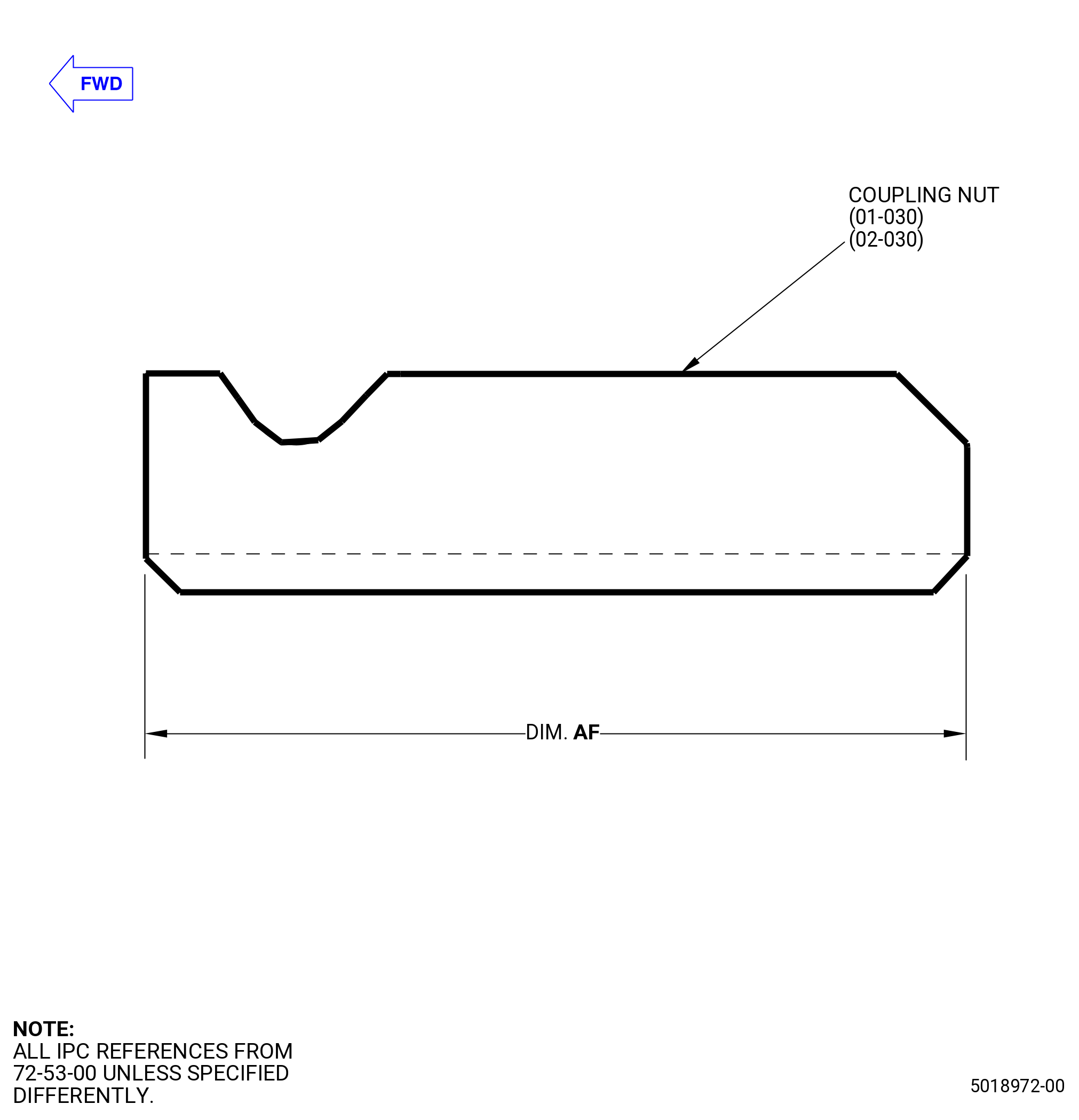
| A. | Before the installation of the coupling nut (01-030) (SIN 150AD) or (02-030) (SIN 150AD), measure the axial length of the coupling nut at four equally spaced locations. Refer to Figure 208 and do as follows: |
| (1) | Record the average value as dimension AF. |
| Dimension AF=______________. |
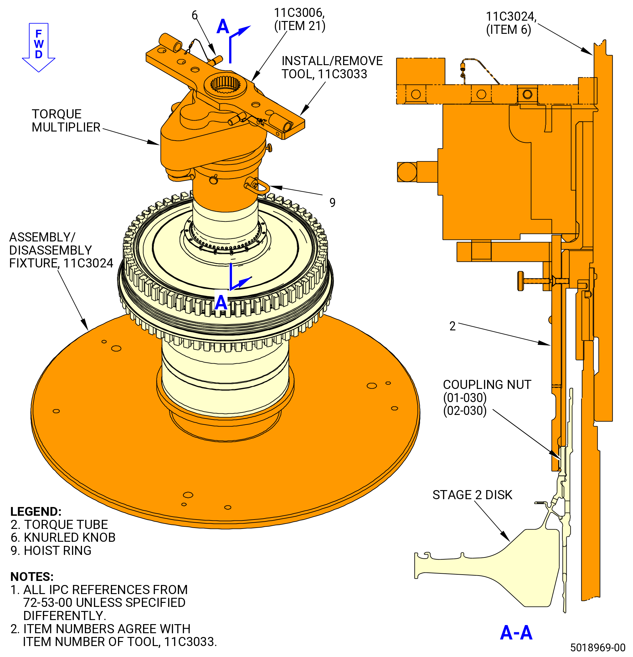
| B. | Apply a final torque to the coupling nut (01-030) (SIN 150AD) or (02-030) (SIN 150AD) with the 11C3033 install/remove tool. Refer to Figure 204 and do as follows: |
| (1) | Use the minimum quantity of lubricant necessary for assembly. After assembly, remove the remaining lubricant with a C10-182 cleaning cloth. |
| WARNING: |
|
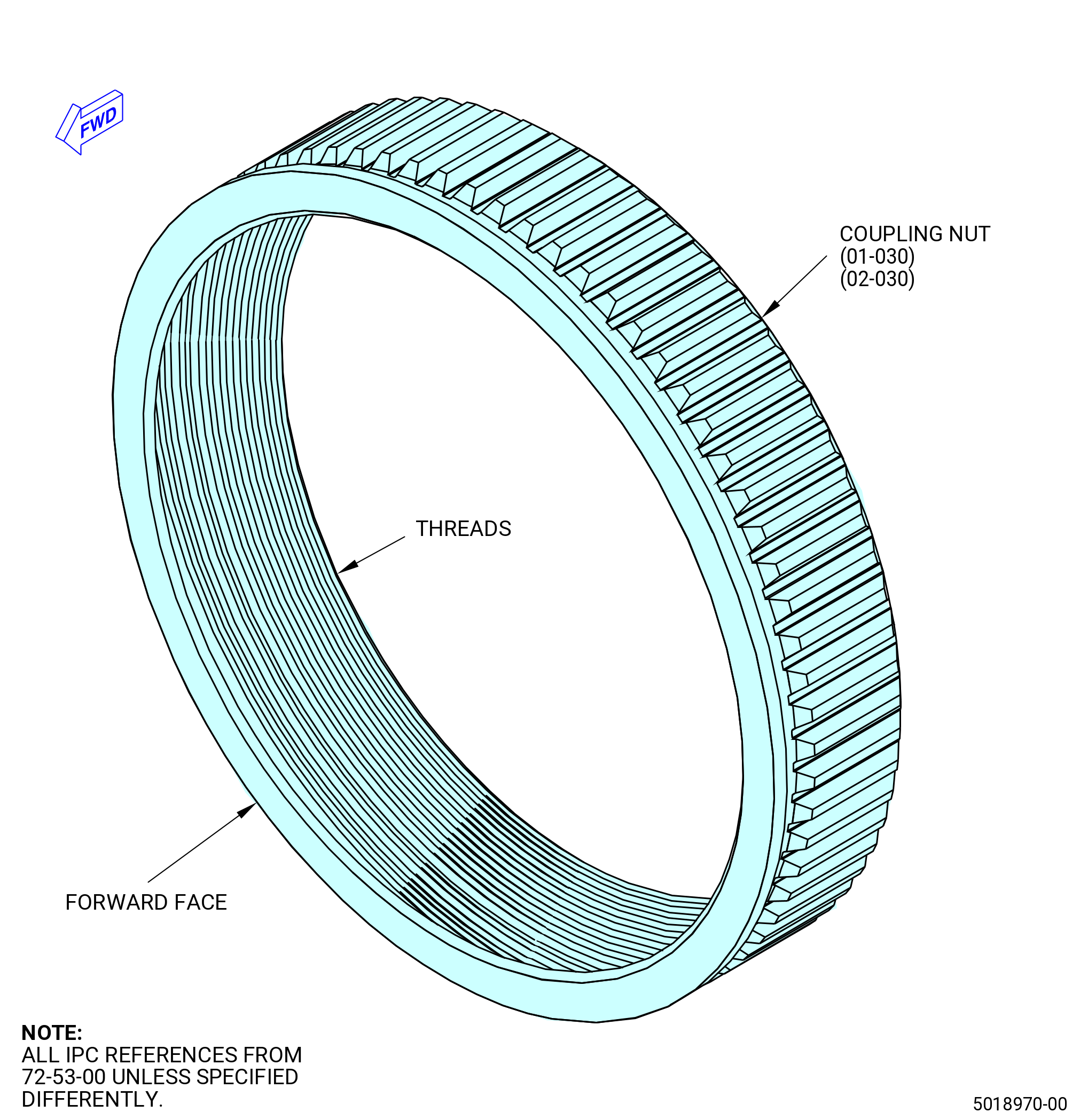
| (2) | Apply C02-058 lubricant to the threads and the forward face of the coupling nut. Refer to Figure 206. |
| WARNING: |
|
| (3) | Attach the coupling nut to the stage 1 disk shaft and manually tighten it against the stage 2 disk. |
| NOTE: |
|
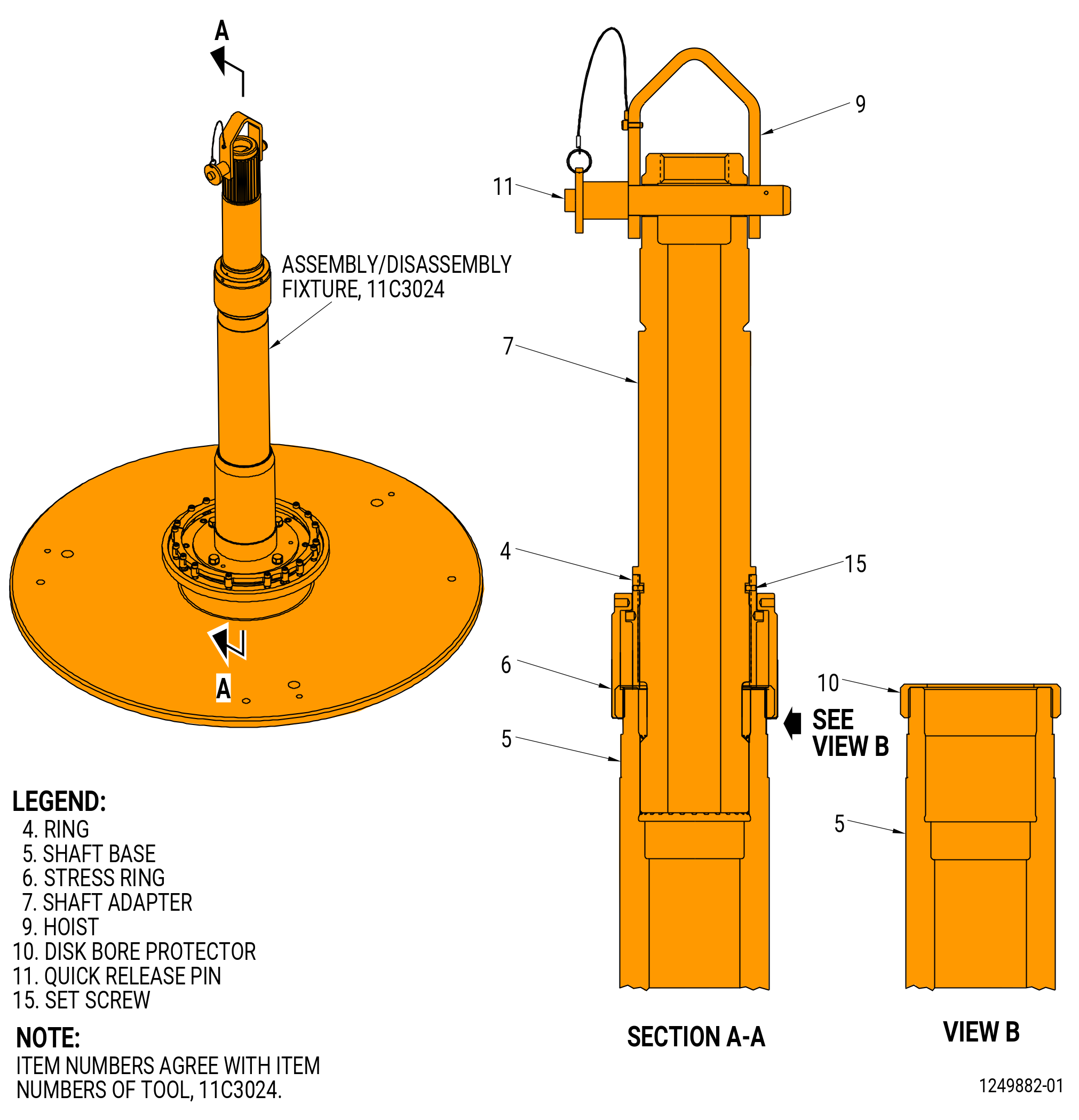
| (4) | Install the shaft adapter (item 7) and stress ring (item 6) on the 11C3024 assembly/disassembly fixture. Refer to Figure 205. |
| WARNING: |
|
| (5) | Attach a three-legged sling to the hoist rings (item 9) to lift the torque tube (item 2) with an overhead hoist. |
| (6) | Install the torque tube (item 2) on the end of the shaft adapter (item 7) of the 11C3024 assembly/disassembly fixture. Engage the torque tube in the splines of the coupling nut. |
| (7) | Use an overhead hoist to lift the torque multiplier and install it on the torque tube (item 2) of the 11C3033 install/remove tool. |
| (8) | Install the torque stop tube (item 3) of the 11C3033 install/remove tool on the shaft adapter (item 7) of the 11C3024 assembly/disassembly fixture. |
| (9) | Make sure that the pins on the torque multiplier are engaged in the holes in the torque stop tube (item 3) of the 11C3033 install/remove tool. |
| (10) | Tighten the knurled knobs (item 6). |
| Subtask 72-53-00-450-002 |
| CAUTION: |
|
| (11) | Alternative Procedure Available. Torque the coupling nut (01-030) (SIN 150AD) or (02-030) (SIN 150AD) as follows: |
| (a) | Use the torque multiplier to tighten the coupling nut to 1,000 lb ft (1,356 N.m). Get the torque and the angle from the 11C3033 install/remove tool. At this point, reset the angle on the digital readout to zero. |
| CAUTION: |
|
| (b) | All actual degrees turned and actual torque values must be recorded on the record sheet. Refer to Table 201 and as follows: |
| 1 | Calculate and record the torque slope for each increment. |
| NOTE: |
|
| NOTE: |
|
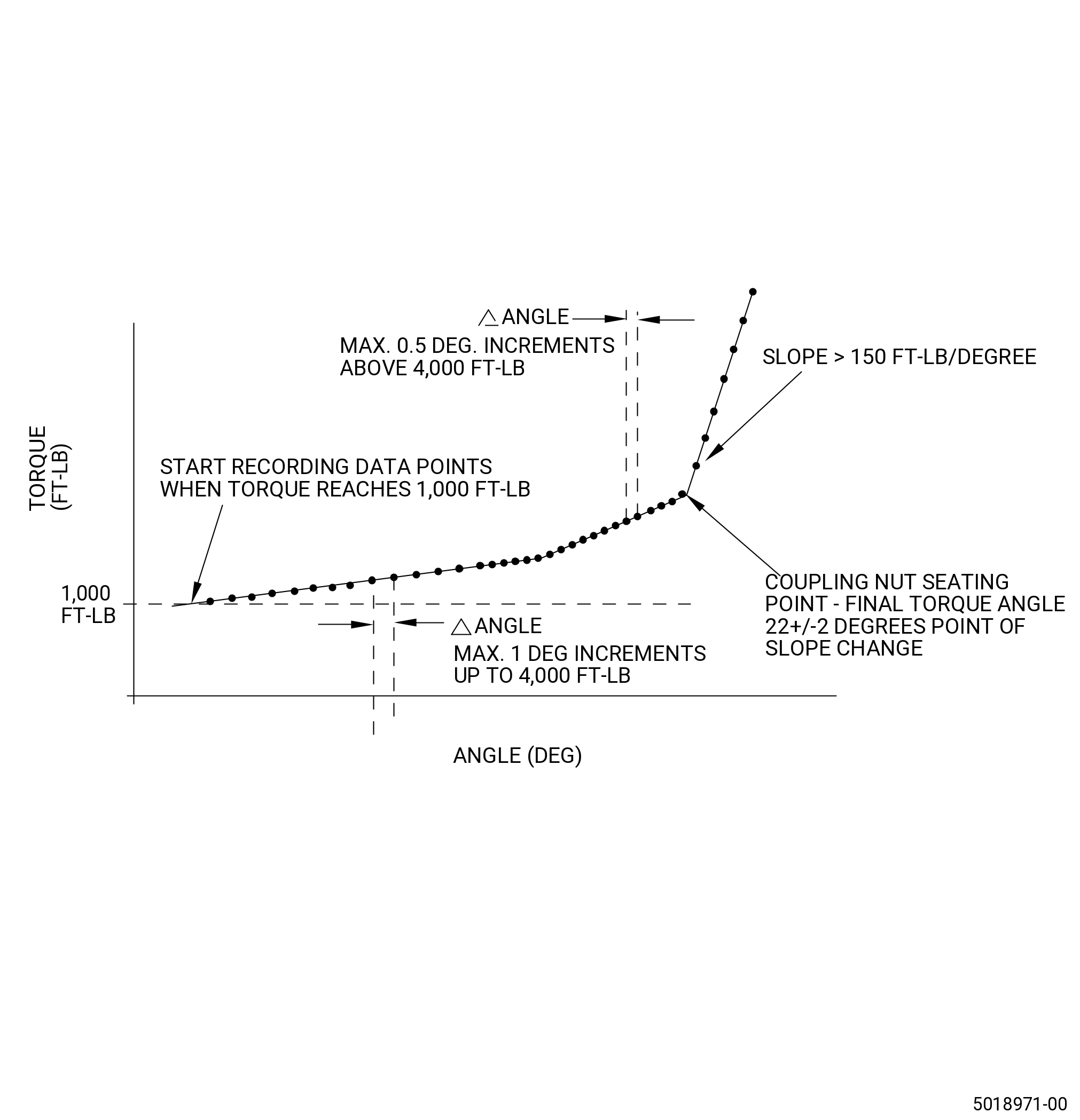
| (c) | Torque the coupling nut in angle increments of no more than 1 degree until the torque gets to 4,000 lb ft (5,424 N.m). Once the torque exceeds 4,000 lb ft (5,424 N.m), torque the coupling nut in increments of no more than 0.5 degrees. |
| (d) | Make a plot of the torque value versus the angle value. Put the torque values on axis Y and the angle value on axis X. |
| (e) | The data will have two changes in the slope. The first shallow change in the slope is not the coupling nut seating point. The second change in the slope is the coupling nut seating point and it is established where the slope first exceeds 150 lb ft/deg (203 N.m/deg). Refer to Figure 207. |
| Subtask 72-53-00-450-005 |
| * * * PRE SB 72-0159 |
| (f) | If the seating point is not found before 8,000 lb ft (10,847 Nm), remove the coupling nut (01-030) (SIN 150AD) and do an inspection of the threads and mating surfaces of the coupling nut, stage 1 disk (01-280) (SIN 150A1), and stage 2 disk (01-130) (SIN 150B1). No galling or missing dry film lube is permitted on the coupling nut. No galling is permitted on the stage 2 disk coupling nut mate face. |
| * * * END PRE SB 72-0159 |
| Subtask 72-53-00-450-006 |
| * * * SB 72-0159 |
| (f).A. | If the seating point is not found before 8,500 lb ft (11,524 Nm), remove the coupling nut (02-030) (SIN 150AD) and do an inspection of the threads and mating surfaces of the coupling nut, stage 1 disk (02-280) (SIN 150A1), and stage 2 disk (02-130) (SIN 150B1). No galling or missing dry film lube is permitted on the coupling nut. No galling is permitted on the stage 2 disk coupling nut mate face. |
| * * * END SB 72-0159 |
| Subtask 72-53-00-450-003 |
| CAUTION: |
|
| (11).A. | Alternative Procedure. Torque coupling nut (01-030) (S1N 150AD) or (02-030) (S1N 150AD) with the 9471M19 coupling nut torque program. Refer to Figure 201 and do as follows: |
| (a) | Turn on the computer and monitor and put the monitor in a position to make it visible from the area where the coupling nut is torqued. Do not start the program at this time. |
| (b) | Adjust the volume on the computer and make sure that it is not in the mute position. The volume must be set loud enough for the operator to hear. If nearby noise is present or an hydraulic wrench with an electric pump is used, adjust the volume to make sure that the program audible signal can be heard over those noises. |
| NOTE: |
|
| CAUTION: |
|
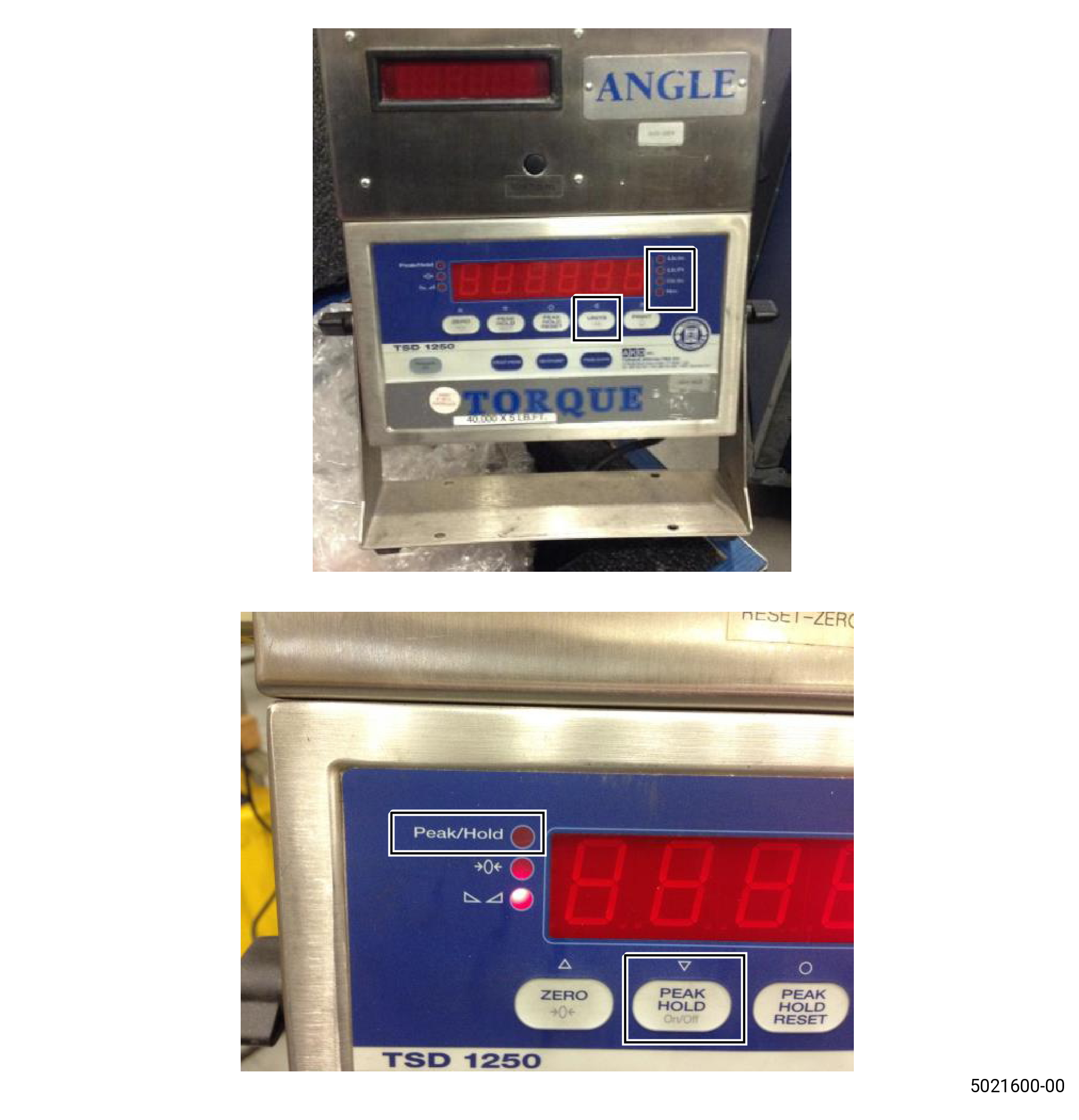
| (c) | Turn off the TORQUE and ANGLE readouts. |
| (d) | Install the cables between the torque tube, encoder, and readout devices. |
| (e) | Install the cables between the readout devices and computer. |
| (f) | Connect the readout devices in and turn on the power for the TORQUE and ANGLE readouts. |
| (g) | Make sure that the unit on the TORQUE readout device is set to ft lb. |
| (h) | Make sure that the light on the Peak/Hold option is off. If not, push the “PEAK HOLD” button until the light turns off. |
| (i) | Start the program. Refer to Figure 202 and do as follows: |
| 1 | Click start, then click on the HPT Coupling Nut Torque folder, and then click on the HPT Coupling Nut Torque executable file. |
| 2 | Optional Procedure. Select the HPT Coupling Nut Torque executable file from the installed location folder. |
| 3 | Select “Run Torque Program” from the main menu. |
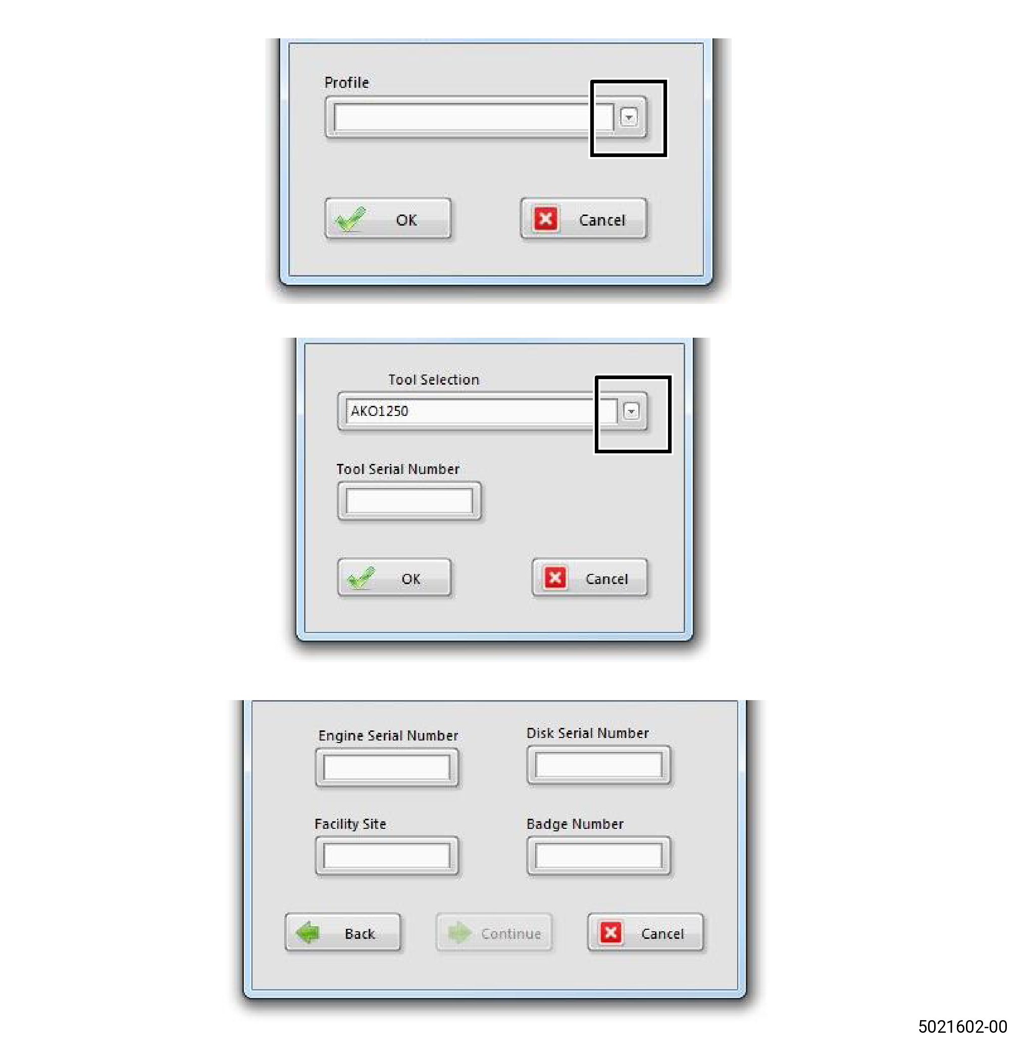
| 4 | Select the engine profile with the drop down menu. Click “OK” after the correct engine profile is selected. |
| 5 | Follow the instructions on the screen to make sure that the TORQUE readout device has the correct adjustments. Refer to paragraph 5.B.(11) A.(g) and paragraph 5.B.(11) A.(h) for more information. |
| 6 | Select “TORQUE readout device being used” from the drop down menu and enter the serial number from the device. Click “OK” to continue. |
| NOTE: |
|
| NOTE: |
|
| 7 | Enter Engine and Stage 1 Disk serial numbers along with site and user’s badge number. Click “Continue” when complete. |
| 8 | Confirm profile settings for the selected engine. If a wrong profile is selected, click cancel and go back to paragraph 5.B.(11) A.i.3, and make sure to select the correct engine profile. The back buttons can also be used to change Tool or Engine Credentials. |
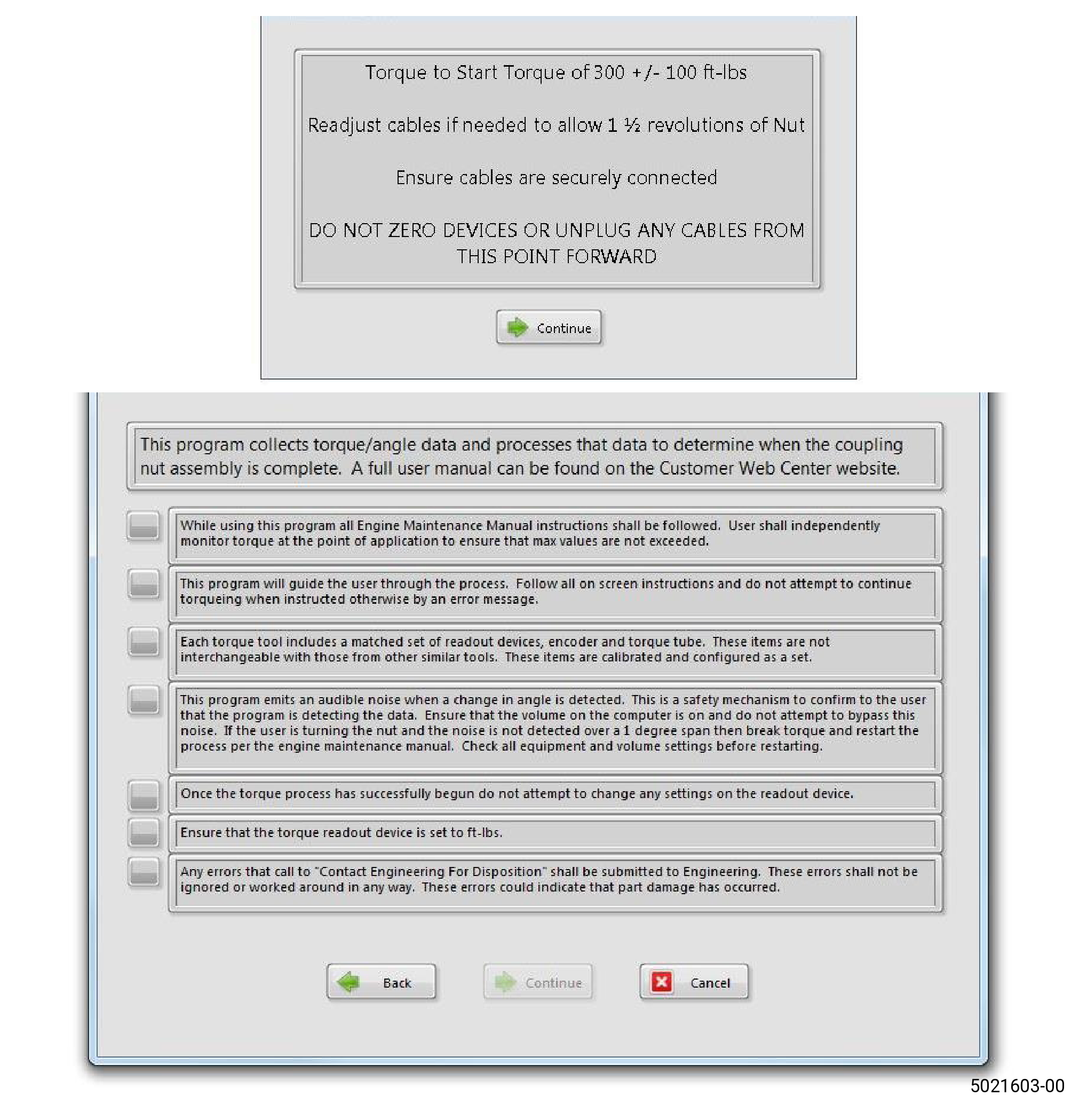
| 9 | With the torque multiplier, follow the on screen instructions for initial torque of the nut and hardware setup. Use the display on the TORQUE readout device for current torque value. The Figure 202 is an example and the value can be different for different applications. If this value is more than the initial value, the program cannot operate correctly. Click “Continue” when the initial torque is complete. |
| CAUTION: |
|
| 10 | Read through all the acknowledgements shown on the screen and check in each box. Click “Continue” once all of the acknowledgements are understood and all boxes are check in. |
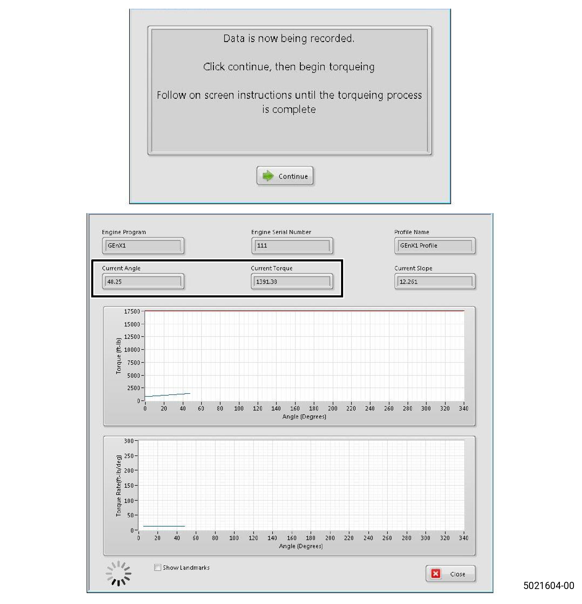
| 11 | At this point, the program will begin to record the data and monitor for errors. Click “Continue” to go to the TORQUE screen and begin the torque process. |
| CAUTION: |
|
| 12 | Begin to apply torque. Make sure that “Current Torque” and “Angle” numbers displayed at the top of the screen match with the readout devices and change while torque is applied. If angle or torque is not changing, check all cables and start the program again. If the applied torque is not more than the initial torque, the nut will not need to be removed and inspected. |
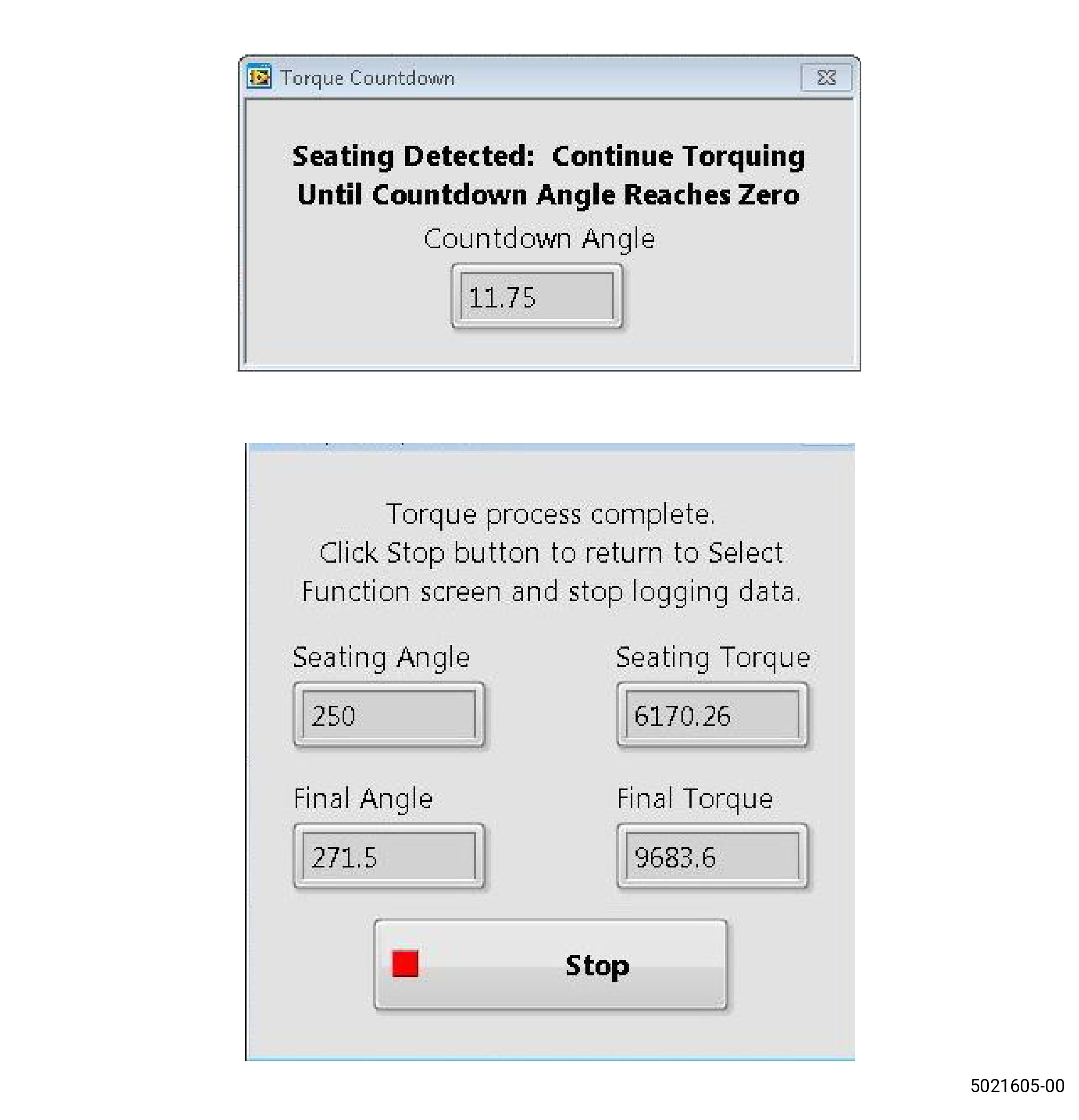
| 13 | After the nut is seated, the program will display a countdown screen. This shows how many degrees of rotation remain until the final angle is engaged. The program will show when the final angle is engaged and torque is complete. |
| CAUTION: |
|
| 14 | When the final angle is engaged and torque is complete a screen is displayed. Stop to apply torque at this time. Refer to Figure 202. |
| 15 | After the final torque data is collected and the nut is seated, click “Stop”. |
| 16 | Review the torque data with the “Data Viewer” included with the software. The last run rotor will automatically populate, but historical data set can be selected for viewing. |
| NOTE: |
|
| 17 | Copy the “.tdms file” that is saved in the program folder to a network drive or other storage location for long term retention. This data is necessary to be available for engineering review. |
| Subtask 72-53-00-450-007 |
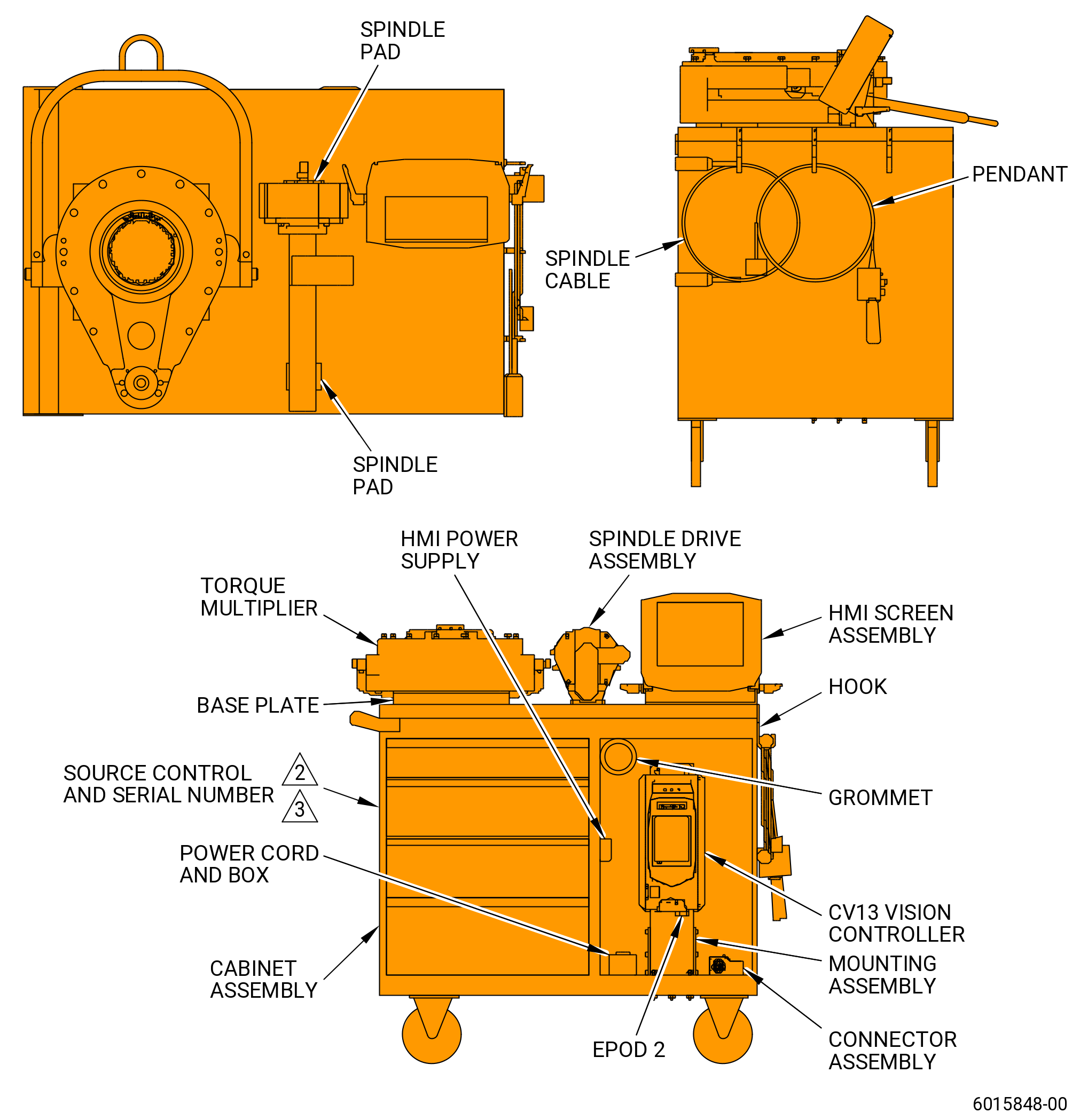
| (11).B. | Alternative Procedure. Torque coupling nut (01-030) (S1N 150AD) or (02-030) (S1N 150AD) with the 9478M31P01 25K SWTS system. Refer to Figure 203 and do as follows: |
| CAUTION: |
|
| (a) | Plug the torque system into a 220V outlet and turn it CW to lock it in position. |
| CAUTION: |
|
| (b) | Press the green power button on the CVI vision controller (P06) to turn the torque system on. |
| (c) | Once the CVI vision controller (P06) is completely booted-up, click on the “Start” button shown on the HMI screen (P07). |
| (d) | Enter your username and engine serial number (without the “TRT” prefix). |
| (e) | Install the spindle drive assembly (P13) on the torque multiplier (P04). |
| (f) | After verifying that both the engine serial number and the engine type are correct, click on the “Torque Engine” button. |
| CAUTION: |
|
| (g) | Once the “Rundown” icon is spinning, press the green button on the handheld remote. |
| (h) | Confirm that the nut has reached a torque of approximately 100 lb ft (135.6 Nm). |
| (i) | Click on the “Proceed” button to advance to the seating operation. |
| (j) | Once the “Seat” icon is spinning, press the green button on the handheld remote. |
| NOTE: |
|
| NOTE: |
|
| (k) | Check the graph on the screen and confirm it follows a smooth upward curve. |
| (l) | Click on the “Proceed” button to advance to the final torque operation of the program. |
| (m) | Once the “Final” icon is spinning, press the green button on the handheld remote. |
| NOTE: |
|
| (n) | Record the seat torque, seating angle, final torque, final angle and angle past seat in the next sequence. |
| (o) | Make sure all data is recorded before performing the next step. |
| (p) | Click on the “Save Plot and Return” button to save the data. |
| (q) | Press the green power button on the CVI vision controller (P06) to turn the torque system off. If required, shut down the system. |
| (r) | Unplug the torque system from the 220V outlet by turning the plug CCW and then pulling it. Make sure to store the power cord back in the cabinet assembly (P02). |
| Subtask 72-53-00-450-004 |
| (12) | The final angle is 20-24 degrees from the coupling nut seating point. If the angle is more than 24 degrees past the seating point during the assembly procedure, record that maximum angle. |
| CAUTION: |
|
| (13) | Use the final degrees calculated as a reference to turn the coupling nut. If Subtask 72-53-00-450-003 (paragraph 5.B.(11) A.) is used, paragraph 5.B.(13) is not necessary. |
| (14) | Record all of the actual degrees turned and actual torque values in Table 201. If Subtask 72-53-00-450-003 (paragraph 5.B.(11) A.) is used, paragraph 5.B.(14) is not necessary. |
| (15) | Remove all torque tooling. |
| (16) | Remove the shaft adapter (item 7) from the 11C3024 assembly/disassembly fixture. Refer to Subtask 72-53-00-440-176 (72-53-00, ASSEMBLY 001, CONFIG 01) or Subtask 72-53-00-440-440 (72-53-00, ASSEMBLY 001, CONFIG 02). |
| (17) | Measure the distance from the aft face of the coupling nut (01-030) (SIN 150AD) or (02-030) (SIN 150AD) to the stage 1 disk aft castellations at four equally spaced locations. Refer to Figure 209 and record the average value as dimension AG. |
| Dimension AG = __________. |
| (18) | Compare measured dimension AG to calculated dimension AG as follows: |
| (a) | Calculated dimension AG = dimension AE - dimension AD - dimension AF. |
| NOTE: |
|
| (b) | Difference = measured dimension AG - calculated dimension AG. |
| NOTE: |
|
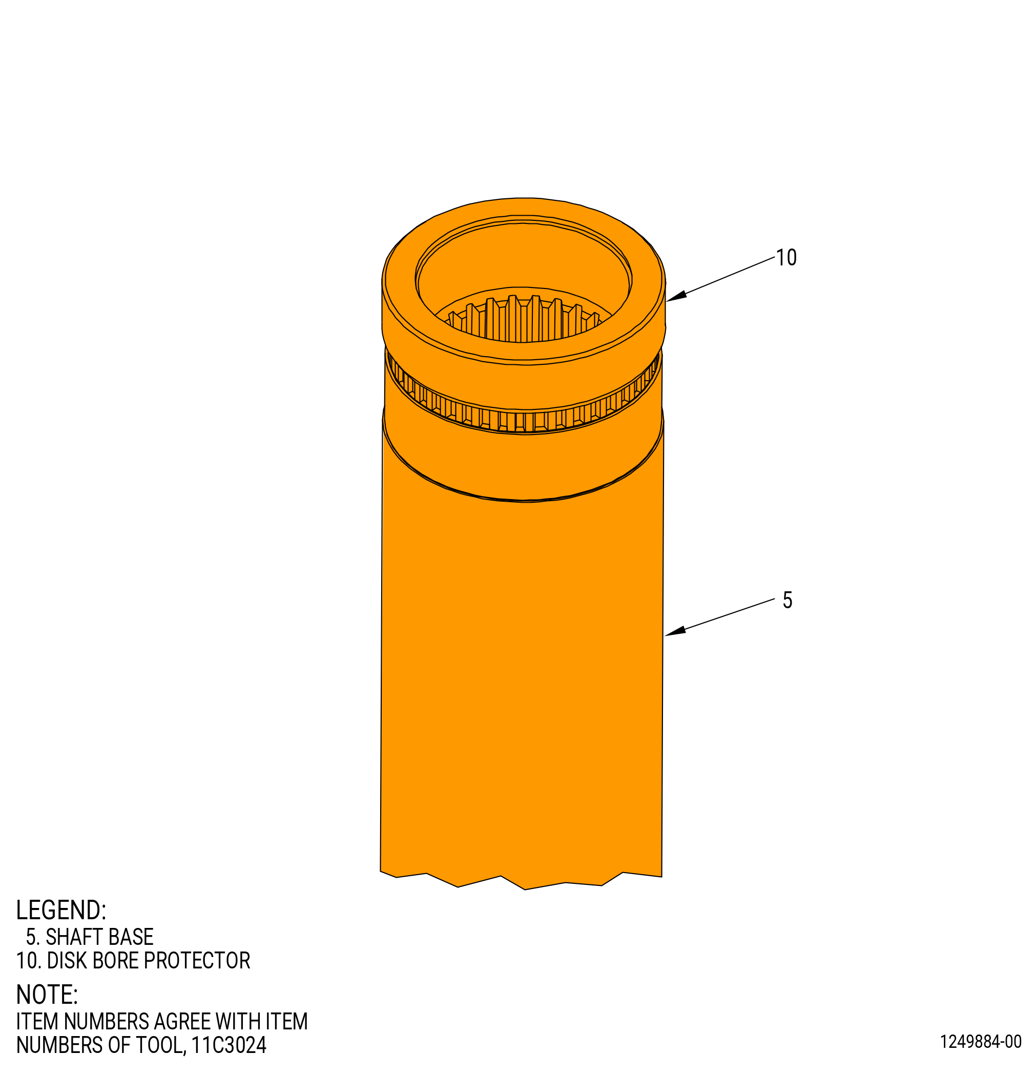
| (19) | Install the bore disk protector (item 10) on the end of the shaft base (item 5) of the 11C3024 assembly/disassembly fixture. Refer to Figure 205. |
| (20) | Let the parts return to room temperature. |
| C. | Record the actual degrees turned and actual torque values. Refer to Table 201. If Subtask 72-53-00-450-003 (paragraph 5.B.(11) A.) is used, paragraph 5.C. is not necessary. |
|