| GENX-1B ENGINE MANUAL | Dated: 08/18/2023 | |
| EM 72-52-00 , ASSEMBLY 001 | ||
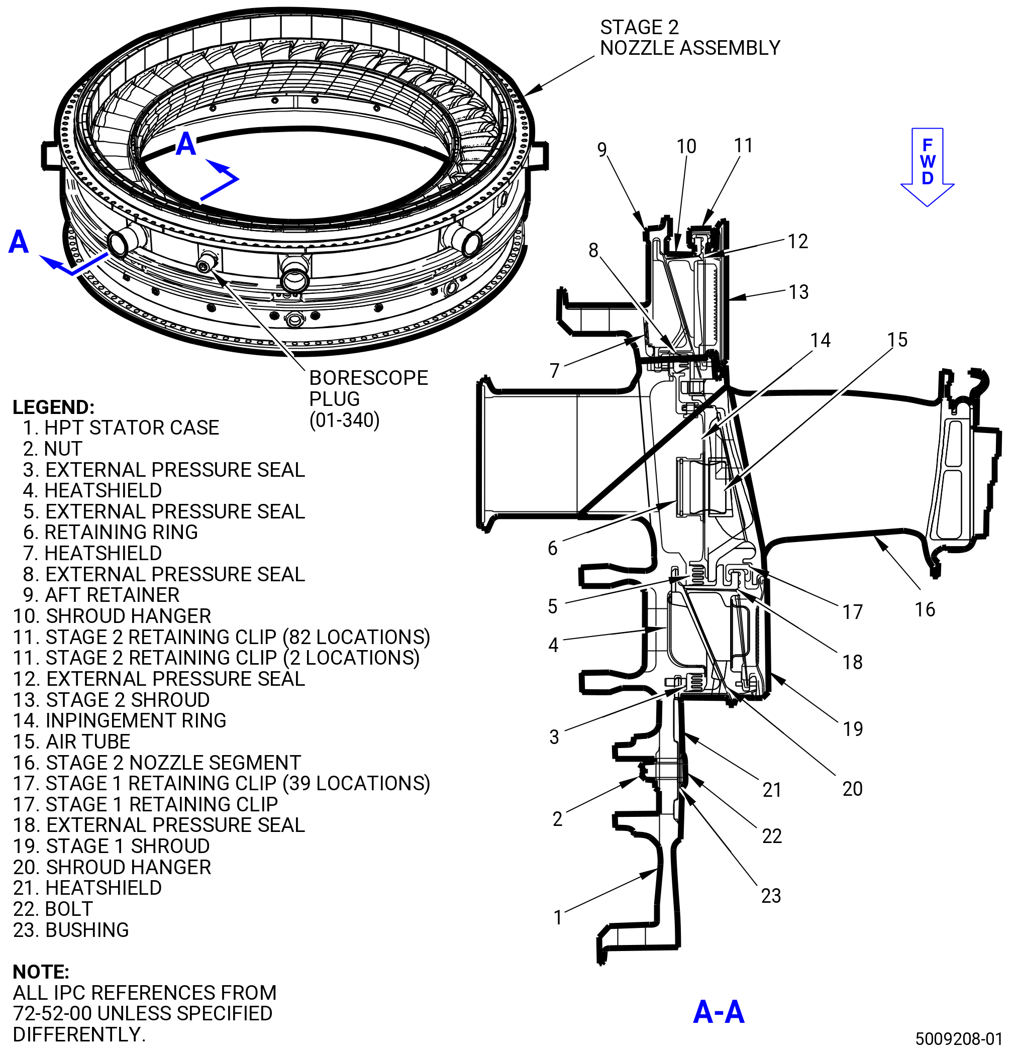
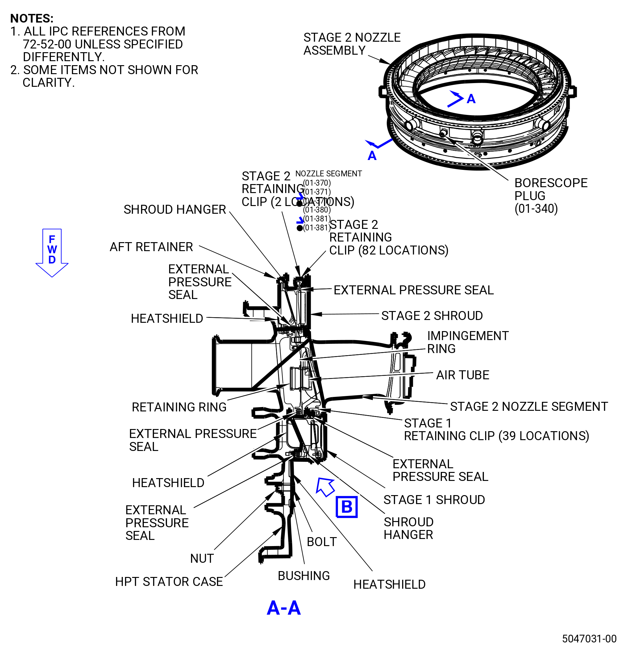
| HIGH PRESSURE TURBINE STAGE 2 NOZZLE ASSEMBLY - ASSEMBLY 001 - CONFIGURATION 02 | ||
| GENX-1B ENGINE MANUAL | Dated: 08/18/2023 | |
| EM 72-52-00 , ASSEMBLY 001 | ||
| HIGH PRESSURE TURBINE STAGE 2 NOZZLE ASSEMBLY - ASSEMBLY 001 - CONFIGURATION 02 | ||
| * * * FOR ALL PIP 2 |
| TASK 72-52-00-440-802 |
| 1 . | General. |
| A. | This procedure gives instructions for the assembly of the HPT stage 2 nozzle assembly (stage 2 nozzle assembly) (34-012 , 72-00-02) (SIN 17400). Refer to Figure 1001. |
| WARNING: |
|
| B. | Before the assembly is done, make sure that all the rabbet and structural flange mating surfaces of the engine parts and tooling are free of foreign material and lifted metal. If necessary, clean the parts with C04-002 Stoddard solvent, C04-003 acetone, C04-035 isopropyl alcohol, or 50-50 blend of C04-035 isopropyl alcohol and C04-228 denatured alcohol. |
| 2 . | Tools, Equipment, and Materials. |
| NOTE: |
|
| A. | Tools and Equipment. |
| (1) | Special Tools. |
| (2) | Standard Tools and Equipment. None. |
| (3) | Locally Manufactured Tools. None. |
| B. | Consumable Materials. |
|
| C. | Referenced Procedures. |
|
| D. | Expendable Parts. |
|
| 3 . | Procedure. |
| Subtask 72-52-00-440-083 |
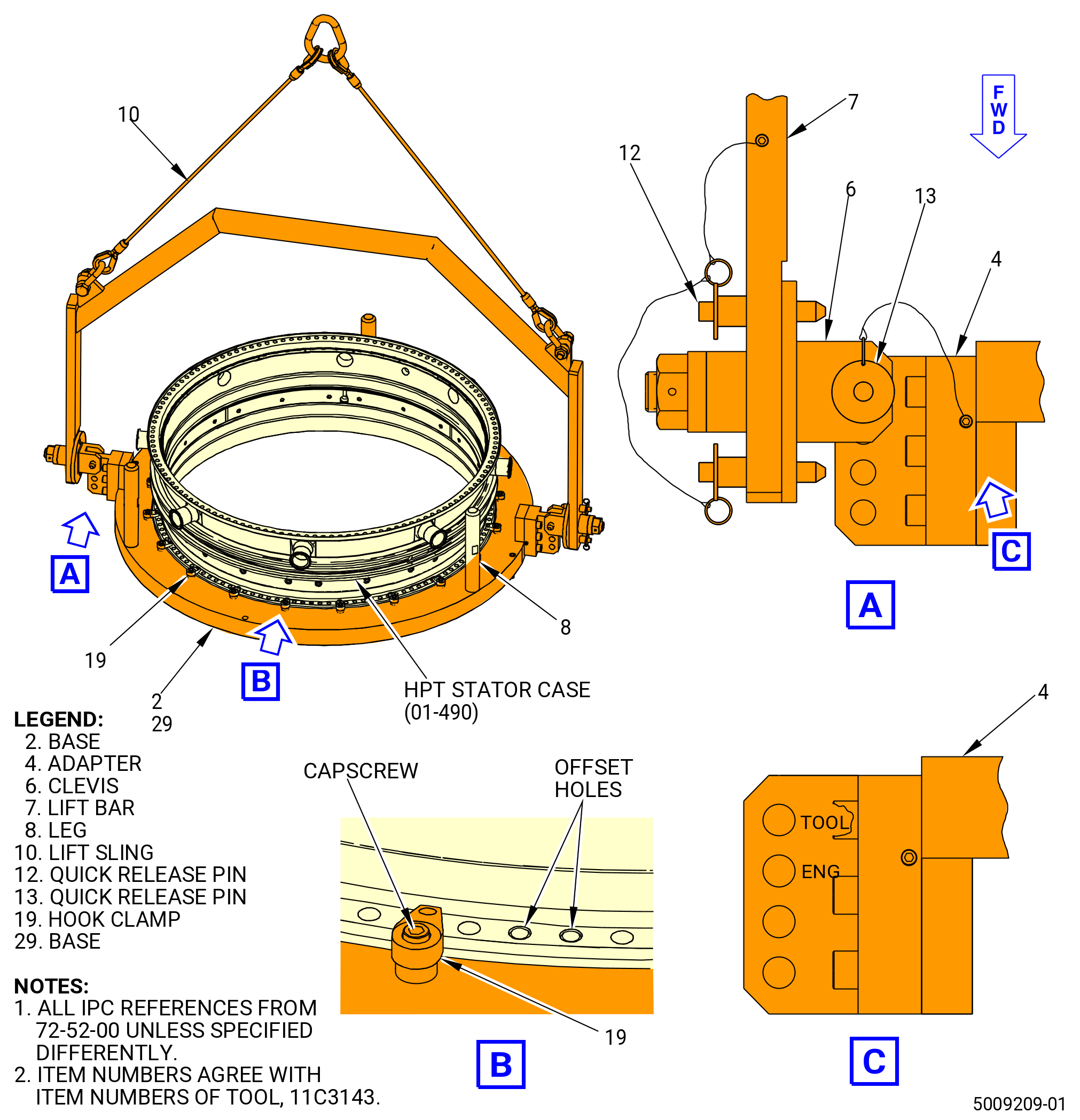
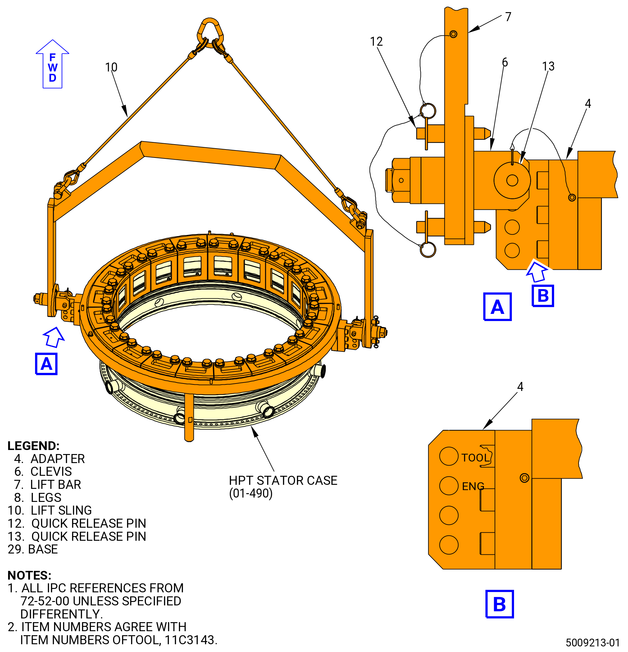
| A. | Turn the 11C3143 hanger install fixture aft side up, as necessary. Refer to Figure 1002. |
| WARNING: |
|
| (1) | Attach the lift sling (item 10) to an overhead hoist. Lift the lift bar (item 7). |
| (2) | Lower the lift bar (item 7) to the adapter (item 4). |
| (3) | Attach the clevises (item 6) to the adapter (item 4) at the hole marked TOOL with the quick release pins (item 13). |
| (4) | Make sure that the quick release pins (item 12) are installed through the lift bar (item 7) and engaged in the plate of the clevises (item 6). |
| (5) | Lift the base (item 2 or item 29) with the hoist. |
| (6) | Remove the quick release pins (item 12). Turn the base (item 2 or item 29) aft side up. Engage the quick release pins (item 12). Lower the base (item 2 or item 29) onto the table. |
| (7) | Remove the quick release pins (item 13) from the clevises (item 6). |
| (8) | Remove the lift bar (item 7) from the adapter (item 4). |
| B. | Install the HPT stator case (01-490) (SIN 174B0) aft side up on the 11C3143 hanger install fixture. Refer to Figure 1002 and do as follows: |
| (1) | Find the word TOP marked on the outer diameter (OD) of the HPT stator case aft flange. Write the words TOP FORWARD, with a C05-003 pen, on the OD of the HPT stator case forward flange. |
| (2) | Loosen the capscrews to put the hook clamps (item 19) away from the step in the base (item 2 or item 29) of the 11C3143 hanger install fixture. |
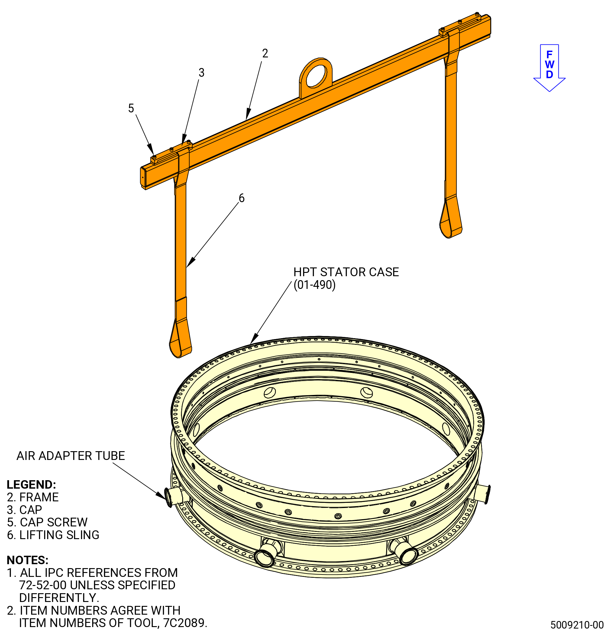
| (3) | Attach the HPT stator case (01-490) (SIN 174B0) to the 7C2089 lift and turn fixture. Refer to Figure 1003 and do as follows: |
| (a) | Attach the 7C2089 lift and turn fixture to an overhead hoist. |
| (b) | Lift and put the 7C2089 lift and turn fixture over the HPT stator case. |
| (c) | Attach the two lifting slings (item 6) to two air adapter tubes on the HPT stator case, 180 degrees apart. Make sure that the straps are perpendicular to the floor. |
| WARNING: |
|
| (4) | Lift the HPT stator case and turn the case forward side down. |
| (5) | Find the TOP VERTICAL mark on the base (item 2 or item 29) of the 11C3143 hanger install fixture. Refer to Figure 1002. |
| (6) | Lower the HPT stator case on the base (item 2 or item 29) of the 11C3143 hanger install fixture and align the top vertical centerlines of the hanger install fixture and the HPT stator case. |
| (7) | Engage the two pins in the base (item 2 or item 29) with the top vertical centerline and offset boltholes of the HPT stator case. |
| (8) | Remove the 7C2089 lift and turn fixture from the HPT stator case. |
| (9) | Put the hook clamps (item 19) of the 11C3143 hanger install fixture over the forward flange of the HPT stator case. |
| (10) | Tighten the capscrews to attach firmly the hook clamps (item 19) against the forward flange of the HPT stator case. Torque the capscrews to 200 lb in. (22.6 N.m). |
| (11) | Install the legs (item 8) on the base (item 2 or item 29). |
|
|
|
| Subtask 72-52-00-440-084 |
| C. | Turn the HPT stator case forward end up with the 11C3143 hanger install fixture. Refer to Figure 1002 and do as follows: |
| WARNING: |
|
| (1) | Attach the lift sling (item 10) to an overhead hoist. Lift the lift bar (item 7). |
| (2) | Lower the lift bar (item 7) to the adapter (item 4). |
| (3) | Attach the clevises (item 6) to the adapter (item 4) with the quick release pins (item 13) at the hole marked ENG. |
| (4) | Make sure that the quick release pins (item 12) are installed through the lift bar (item 7) and engaged in the plate of the clevises (item 6). |
| (5) | Lift the HPT stator case with the hoist. |
| (6) | Disengage the quick release pins (item 12). Turn the HPT stator case forward end up. Engage the quick release pins (item 12). |
| (7) | Lower the HPT stator case to a table until the fixture is on the three legs (item 8). |
| (8) | Remove the quick release pins (item 13) from the clevises (item 6). Remove the lift bar (item 7) from the adapter (item 4). |
| Subtask 72-52-00-440-085 |
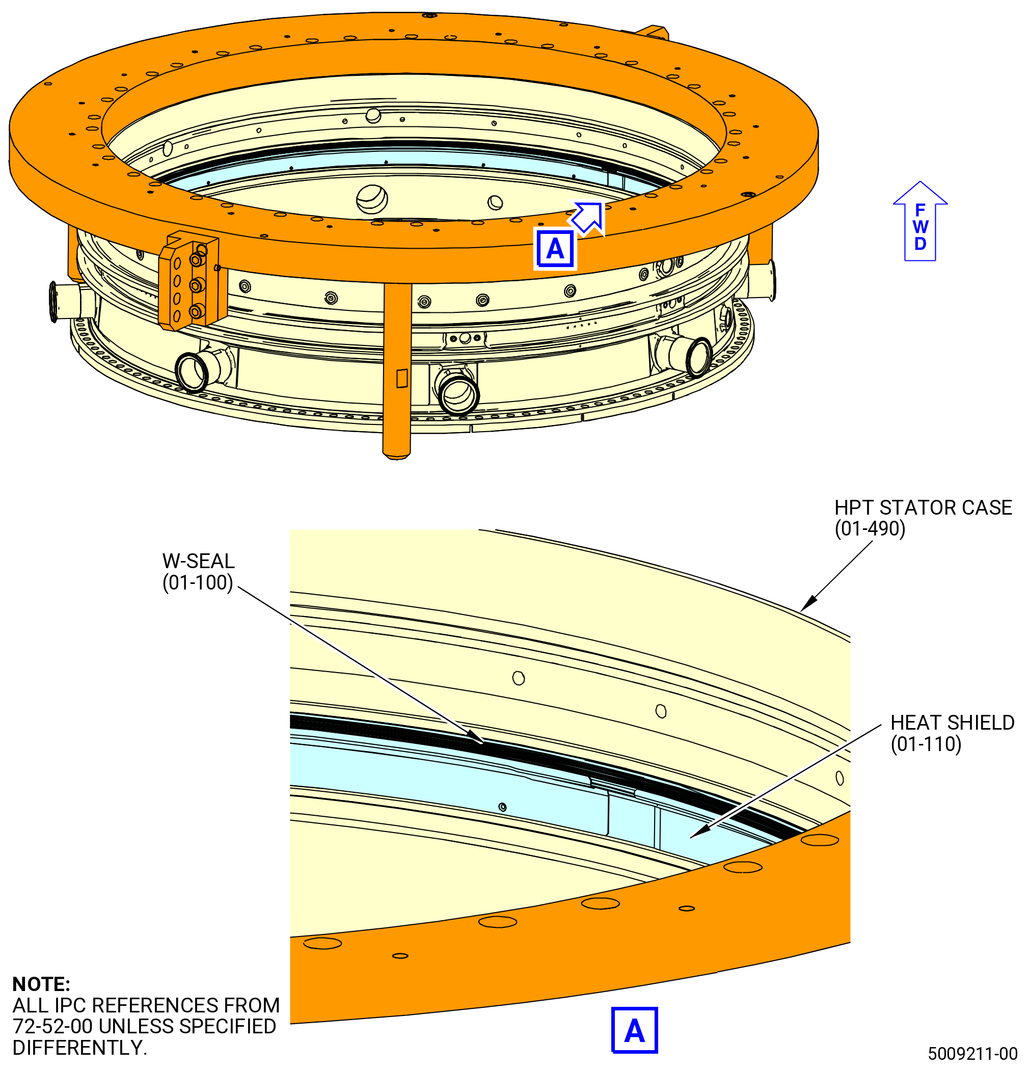
| D. | Install the external pressure seal (W-Seal) (01-100) (SIN 17350), heat shield (01-110) (SIN 173A6) and stage 1 shroud hangers (shroud hangers) (01-081) (SIN 17301) in the HPT stator case (01-490) (SIN 174B0) as follows: |
| (1) | Install the W-seal on the forward rail in the HPT stator case. Use C10-154 beeswax, C10-109 utility wax, or C01-037 adhesive at several locations between the OD of the external seal and the inner diameter of the HPT stator case to hold the external seal in position. Refer to Figure 1004. |
| NOTE: |
|
| (2) | Let the C10-154 beeswax, C10-109 utility wax, or C01-037 adhesive air dry until tacky. Approximately five minutes. |
| (3) | Install the heat shield in the recessed area under the forward rail of the HPT stator case. Use C10-154 beeswax, or C10-109 utility wax at several locations to hold the heat shield in position. |
| NOTE: |
|
| NOTE: |
|
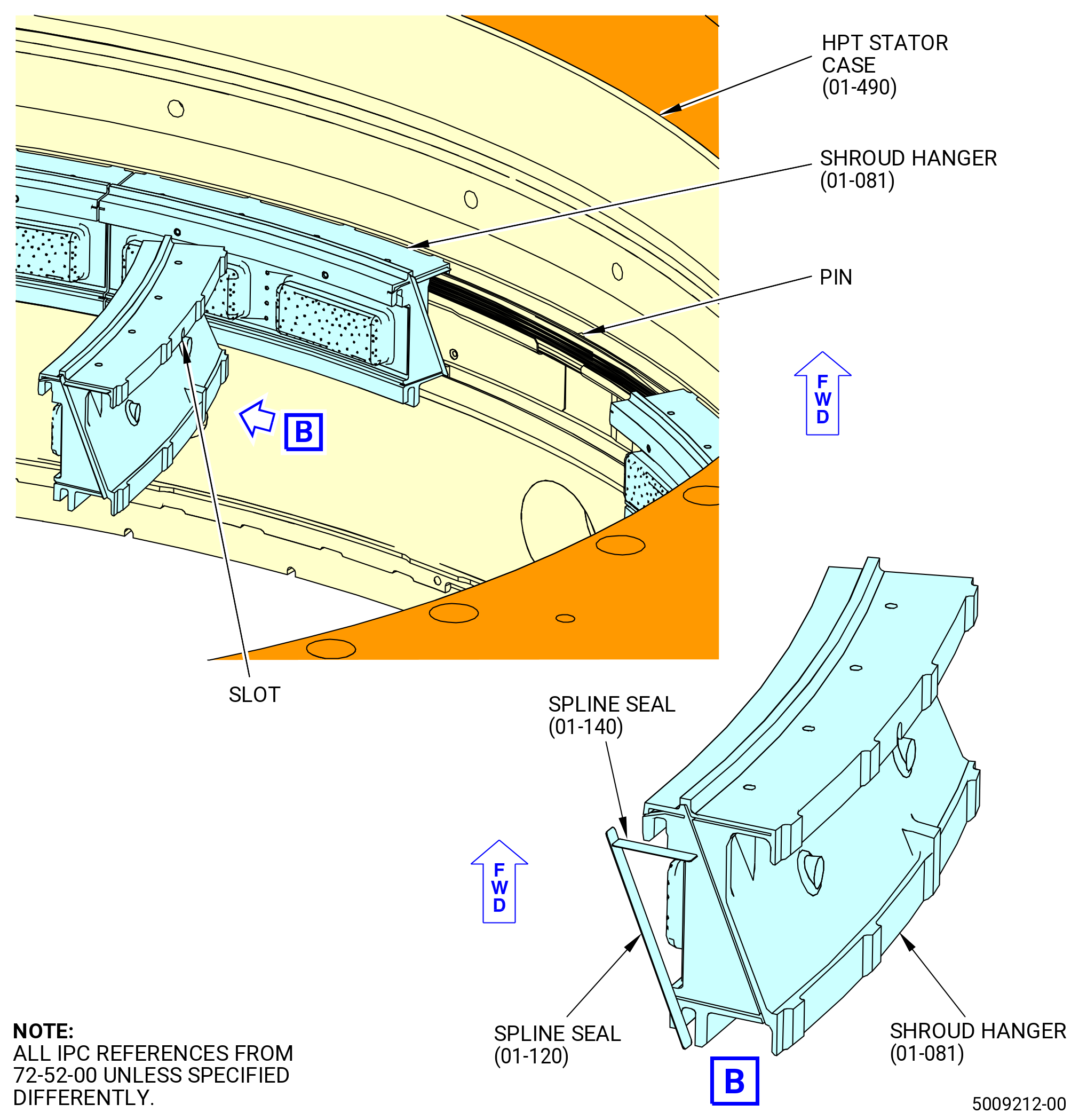
| (4) | Put a mark with a C05-003 pen on the forward face of each shroud hanger to indicate the location of the antirotation slot in order to make the alignment of the slot with the pin in the case easier to see during the assembly. Refer to Figure 1005. |
| (5) | Apply a small quantity of C10-154 beeswax, C10-109 utility wax, C02-033 lubricant, or C01-037 adhesive to the seal slots on the same end of each shroud hanger. |
| NOTE: |
|
| Subtask 72-52-00-440-145 |
| * * * PRE SB 72-0391 |
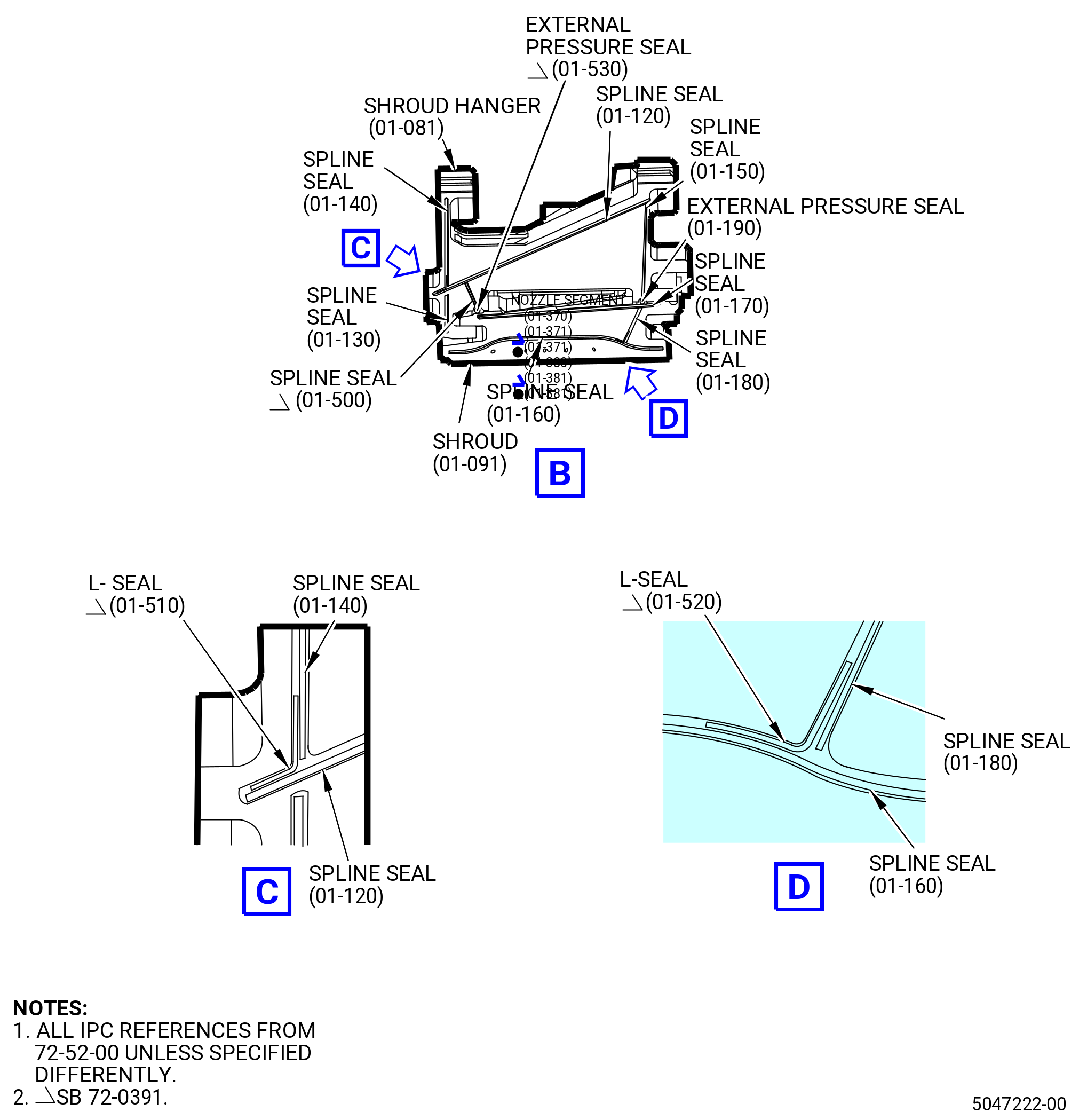
| (6) | Install the spline seals (01-120) (SIN 17302) and (01-140) (SIN 17304) in the waxed end of the shroud hangers. |
| * * * END PRE SB 72-0391 |
| Subtask 72-52-00-440-138 |
| * * * SB 72-0391 |
| (6).A. | Install the spline seals (01-120) (SIN 17302), (01-130) (SIN 17308), (01-140) (SIN 17304), and L-seal (01-510) (SIN 1730K) in the waxed end of the shroud hangers. |
| * * * END SB 72-0391 |
| Subtask 72-52-00-440-139 |
| (7) | Make sure the spline, seals (01-120) (SIN 17302) do not protrude beyond the length of the slot in the shroud hangers. |
| WARNING: |
|
| (8) | Apply C02-003 lubricant to the forward rails and inboard faces of the shroud hangers. |
| (9) | Install a shroud hanger at the 12:00 o'clock position until the pin in the HPT stator case engages the antirotation slot in the hanger. |
| CAUTION: |
|
| (10) | Continue to loosely install the shroud hangers in a circumferential direction engaging the seals with the seal slots of the adjacent shroud hanger. |
| (11) | Move as many shroud hangers together as necessary to make room for the last shroud hanger. |
| (12) | Install the last shroud hanger into the HPT stator case. |
| (13) | Carefully move the shroud hangers apart in small increments to evenly space the end clearance. Make sure that the seals remain engaged with the shroud hangers. |
| (14) | Align the antirotation slots of the shroud hangers with the pins in the HPT stator case and press the shroud hangers down to engage the pins. |
| (15) | Make sure that the forward and aft edges of the stage 1 shroud hanger are against the inner diameter (ID) of the HPT stator case. |
| (16) | Make sure that the hanger seals are engaged in the grooves of the adjacent stage 1 shroud hanger. |
| (17) | Make sure that all the pins and antirotation slots are aligned and engaged. |
| CAUTION: |
|
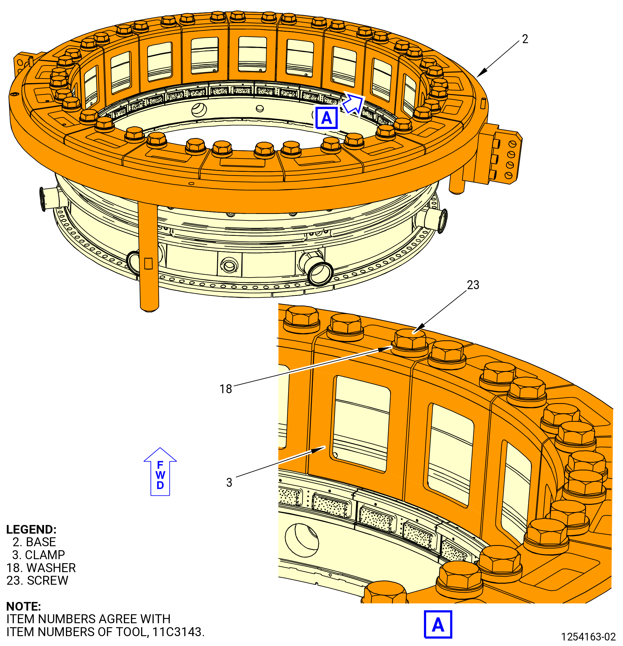
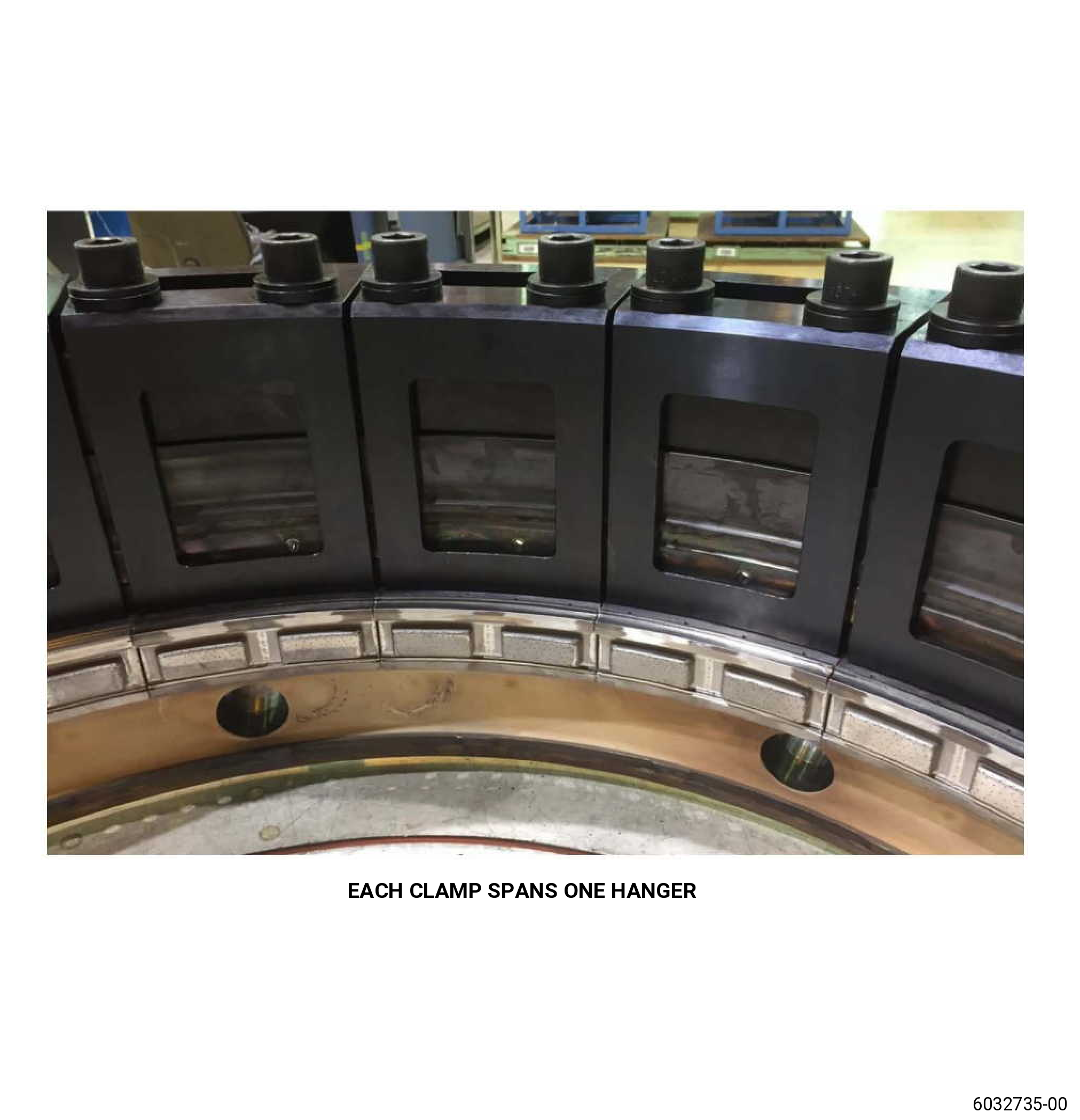
| (18) | Install the clamps (item 3) of the 11C3143 hanger install fixture. Refer to Figure 1006 and do as follows: |
| (a) | Put the clamps so the feet are radially between the lifted shoulder and the outer edge of each stage 1 shroud hanger. |
| NOTE: |
|
| (b) | Attach firmly the clamps to the base (item 2 or item 29) with washers (item 18) and screws (item 23) hand-tight. |
| CAUTION: |
|
| (c) | Turn the screws (item 23) one-half of one turn at a time. Continue until the stage 1 shroud hangers are against the HPT stator case. |
| (d) | Circle torque the screws (item 23) to 420 lb in. (47.5 Nm). |
| (e) | Use a rubber mallet to hit each clamp to make sure that the stage 1 shroud hangers are completely seated. |
| (f) | Circle re-torque the screws (item 23) to 420 lb in. (47.5 Nm). |
| (g) | Use a bright light and pick to make sure that the seals are engaged in the forward side of the stage 1 shroud hangers. Make sure that no damage occurred to the seal or shroud hangers. |
| NOTE: |
|
|
|
| Subtask 72-52-00-440-086 |
| (19) | Turn the HPT stator case forward end down with the 11C3143 hanger install fixture. Refer to Figure 1007 and do as follows: |
| WARNING: |
|
| (a) | Attach the lift sling (item 10) to an overhead hoist. Lift the lift bar (item 7). |
| (b) | Lower the lift bar (item 7) to the adapter (item 4). |
| (c) | Attach the clevises (item 6) to the adapter (item 4) with the quick release pins (item 13) at the hole marked ENG. |
| (d) | Make sure that the quick release pins (item 12) are installed through the lift bar (item 7) and engaged in the plate of the clevises (item 6). |
| (e) | Lift the HPT stator case with the hoist. |
| (f) | Disengage the quick release pins (item 12). Turn the HPT stator case forward end down. Engage the quick release pins (item 12). |
| (g) | Lower the HPT stator case to a table. |
| (h) | Remove the quick release pins (item 13) from the clevises (item 6). Remove the lift bar (item 7) from the adapter (item 4). |
| Subtask 72-52-00-220-054 |
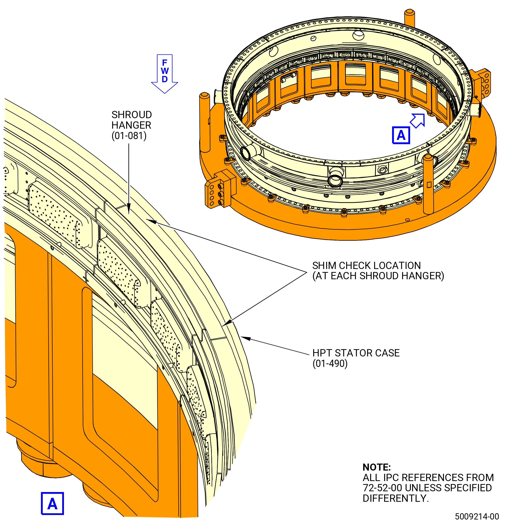
| (20) | Do a shim check to make sure that the shroud hangers are correctly installed in the HPT stator case. Refer to Figure 1008 and do as follows: |
| (a) | Use a 0.002 inch (0.05 mm) shim stock. |
| (b) | Make sure that the shim stock cannot go between the shroud hanger and the case. |
| (c) | Do the check near the ends of each shroud hanger. |
| Subtask 72-52-00-440-087 |
| (d) | If the shim check shows that one or more of the shroud hangers are not installed correctly, do the procedure that follows: |
| 1 | Turn the HPT stator case forward end up in the 11C3143 hanger install fixture. Refer to Subtask 72-52-00-440-084 (paragraph 3.C.). |
| 2 | Increase torque on the screws (item 23) of the hangers that are not completely seated to 478 lb in (54 Nm). Refer to Figure 1006. |
| 3 | Turn the HPT stator case forward end down in the 11C3143 hanger install fixture. Refer to Subtask 72-52-00-440-086 (paragraph 3.D.(19)). |
| 4 | Do the shim check again. Refer to Subtask 72-52-00-220-054 (paragraph 3.D.(20)). |
| Subtask 72-52-00-440-088 |
| * * * PRE SB 72-0391 |
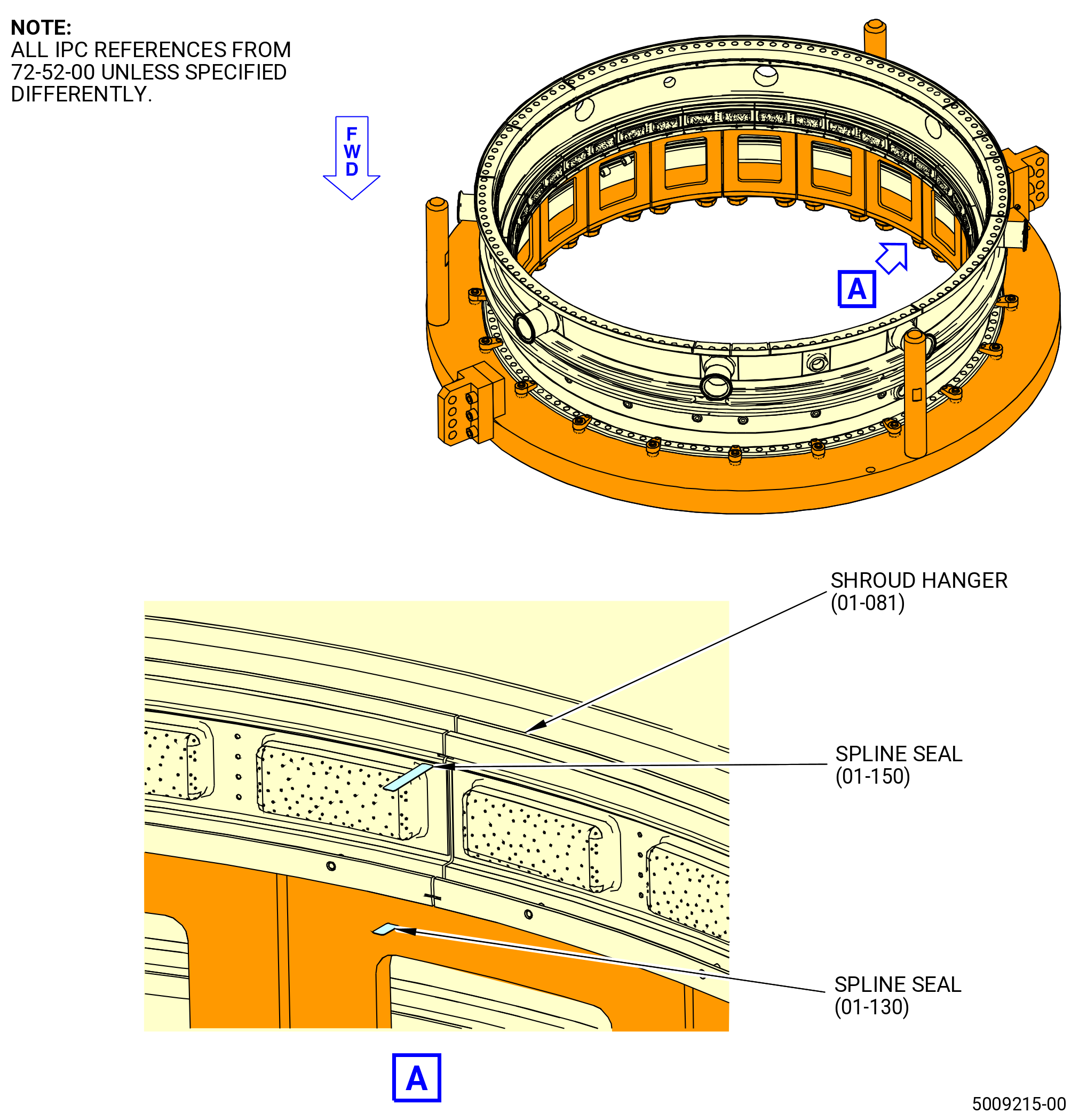
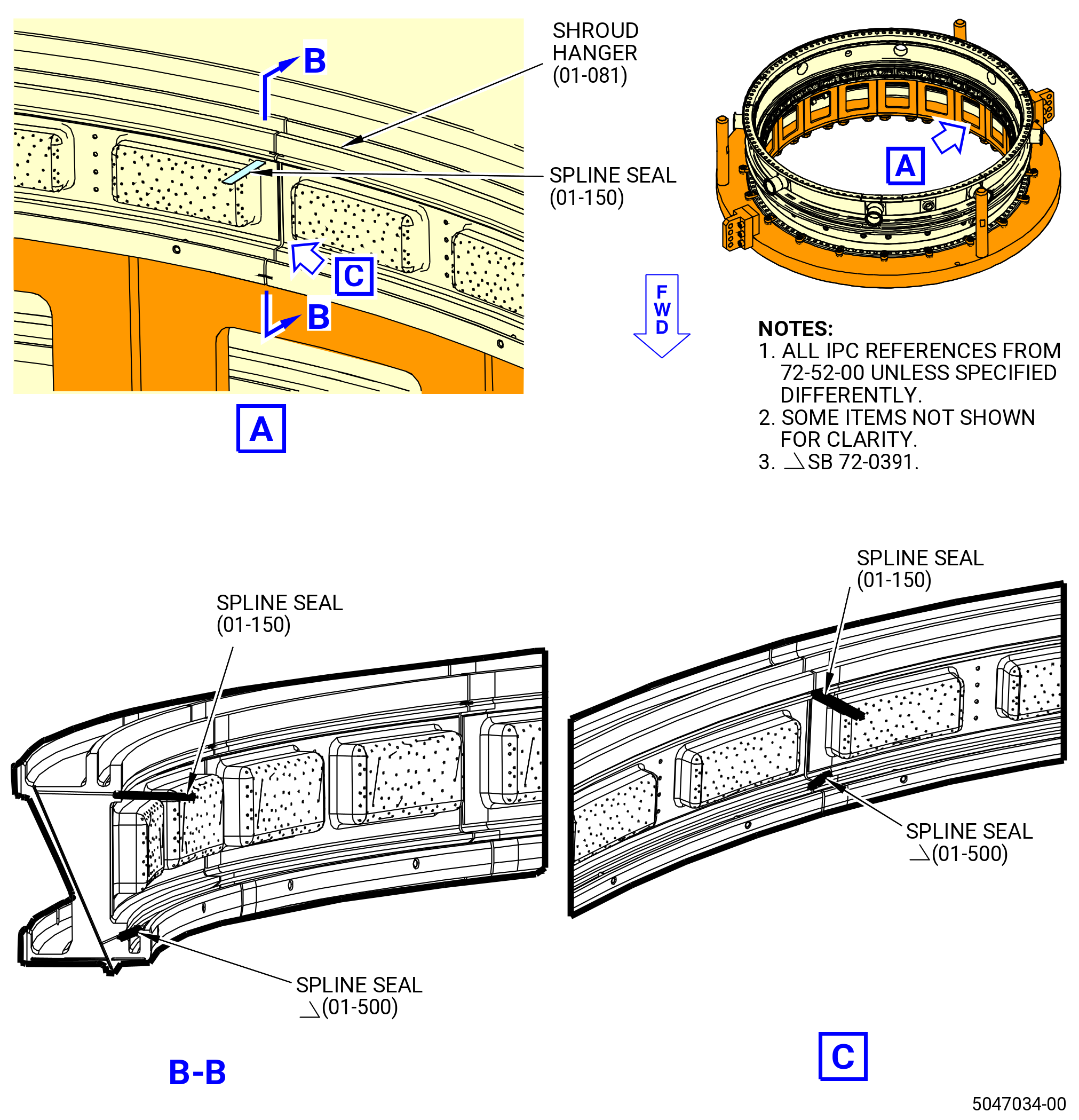
| (21) | Install the spline seals (01-150) (SIN 17303) and (01-130) (SIN 17308). Refer to Figure 1009 and do as follows: |
| (a) | Apply a small quantity of C10-154 beeswax, C10-109 utility wax, C02-033 lubricant, or C01-037 adhesive to the spline seals. |
| (b) | Install the spline seals between the ends of each shroud hanger. Make sure that the spline seals engage the slots of the two shroud hangers at each location. |
| * * * END PRE SB 72-0391 |
| Subtask 72-52-00-440-140 |
| * * * SB 72-0391 |
| (21).A. | Install the spline seals (01-150) (SIN 17303) and spline seal (01-500) (SIN 1730J). Refer to Figure 1009 and do as follows: |
| WARNING: |
|
| (a) | Apply a small quantity of C10-154 beeswax , C10-109 utility wax, C02-033 lubricant, or C01-037 adhesive to the spline seals. |
| (b) | Install the spline seals between the ends of each shroud hanger. Make sure that the spline seals engage the slots of the two shroud hangers at each location. |
| * * * END SB 72-0391 |
| Subtask 72-52-00-440-141 |
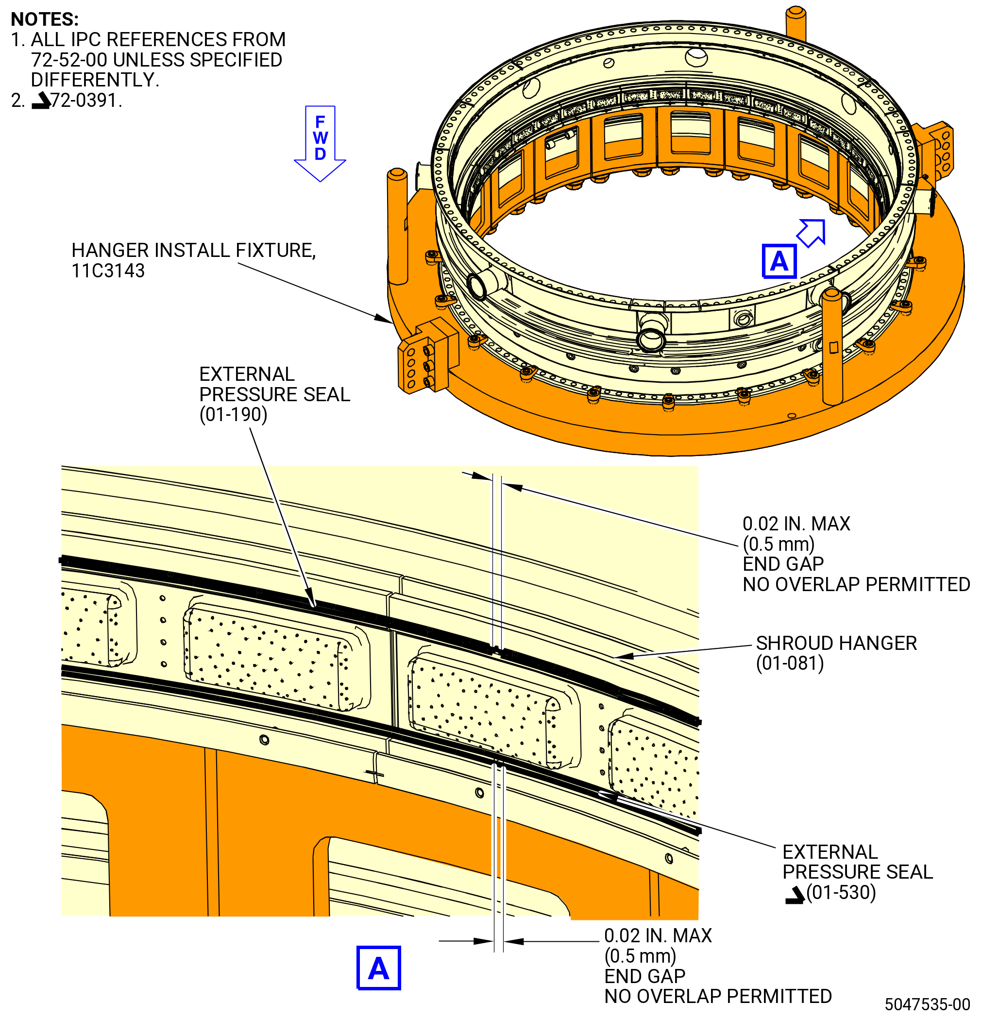
| (22) | Install the external pressure seal (01-190) (SIN 17353) to the shroud hangers (01-081) (SIN 17301). Refer to Figure 1010 and do as follows: |
| (a) | Use a hypodermic syringe filled with C01-050 adhesive CL-A or CL-B to fill the external pressure seal groove in the shroud hanger half full. |
| (b) | Let the adhesive air dry until tacky (approximately seven minutes). |
| (c) | Install the external pressure seal in the groove on the shroud hangers. |
| (d) | If a non 360-degree external pressure seal is used, align the splice joint to 0.50 inch (12.7 mm) of the centerline of the stage 1 shrouds. Make sure that the clearance of the splice joint is 0.02 inch (0.5 mm) or less. Do not overlap the ends of the pressure seal. |
| NOTE: |
|
| (e) | Remove excessive adhesive from the outside of the groove. |
| Subtask 72-52-00-440-142 |
| * * * SB 72-0391 |
| (22).A. | Install the external pressure seal (01-530) (SIN 17354) to the shroud hangers (01-181) (SIN 17301). Refer to Figure 1010 and do as follows: |
| WARNING: |
|
| (a) | Use a hypodermic syringe filled with C01-050 adhesive CL-A or CL-B to fill the forward external pressure seal groove in the shroud hanger half full. |
| (b) | Let the adhesive air dry until tacky (approximately seven minutes). |
| (c) | Install the external pressure seal in the groove on the shroud hangers. |
| (d) | If a non 360-degree external pressure seal is used, align the splice joint to 0.50 inch (12.7 mm) of the centerline of the stage 1 shrouds. Make sure that the clearance of the splice joint is 0.02 inch (0.5 mm) or less. Do not overlap the ends of the pressure seal. |
| NOTE: |
|
| (e) | Remove excessive adhesive from the outside of the groove. |
| * * * END SB 72-0391 |
|
|
|
|
| Subtask 72-52-00-440-089 |
| E. | Assemble the HPT stage 1 shrouds (shrouds) (01-091) (SIN 17300) on the shroud hangers (01-081) (SIN 17301) as follows: |
| Subtask 72-52-00-440-146 |
| * * * PRE SB 72-0391 |
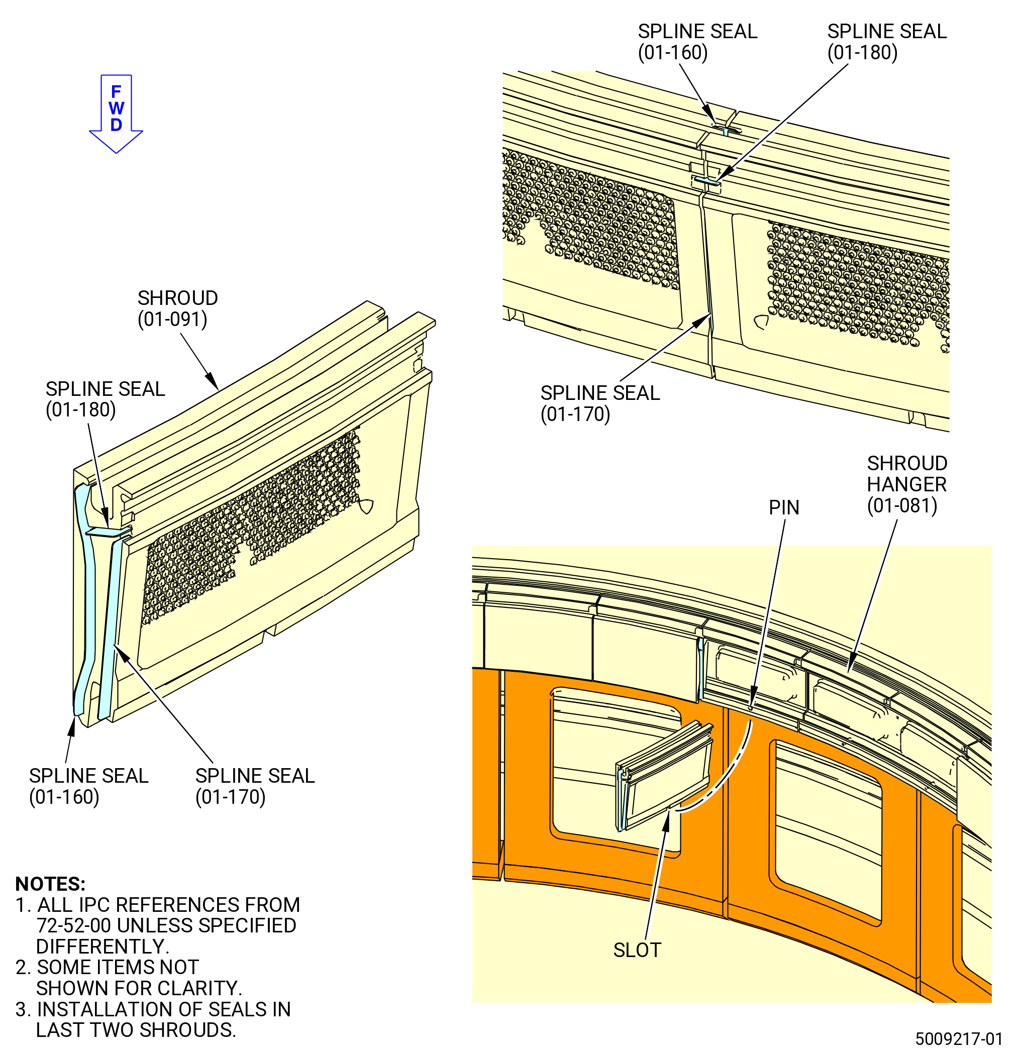
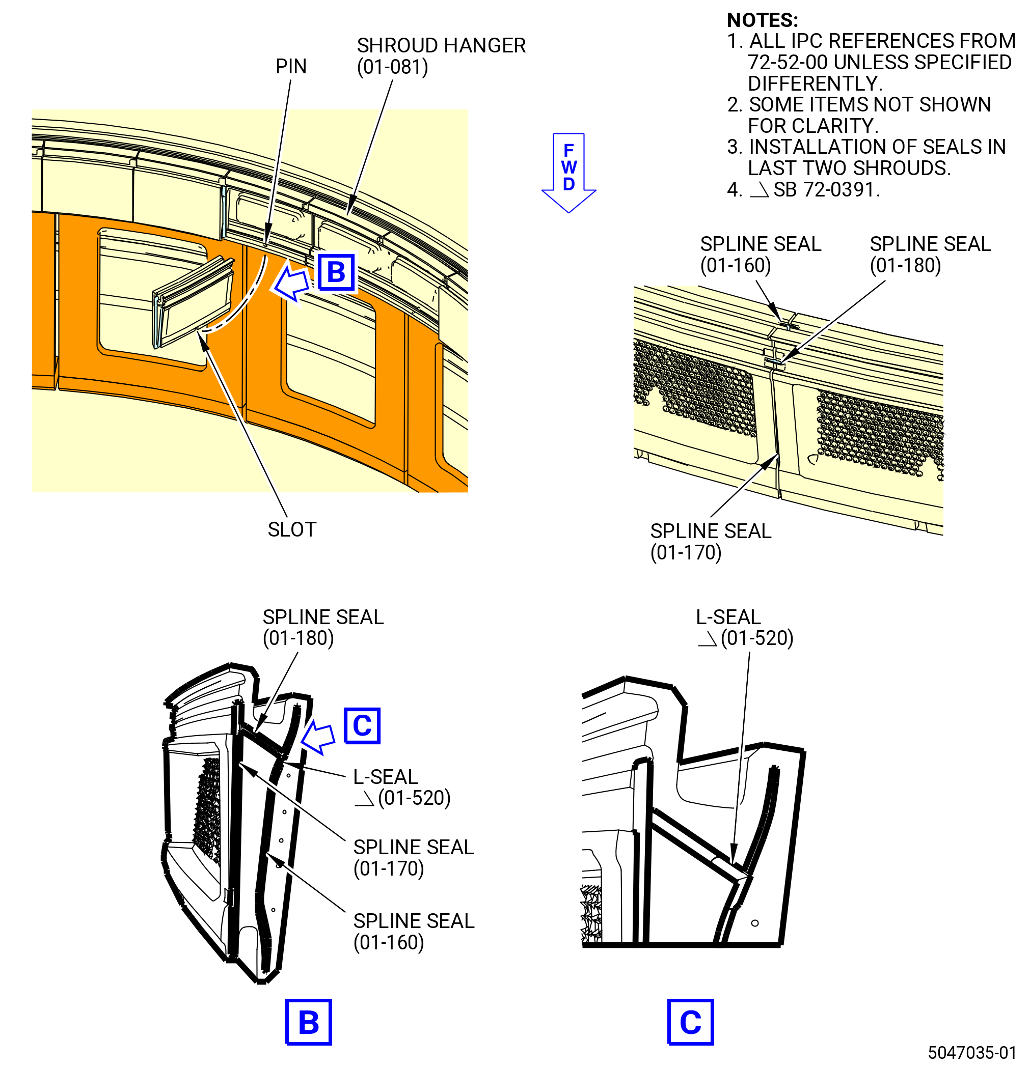
| (1) | Install the spline seals (01-180) (SIN 17305), (01-160) (SIN 17306), and (01-170) (SIN 17307) on the same side of all 40 shrouds. Refer to Figure 1011 and do as follows: |
| NOTE: |
|
| WARNING: |
|
| (a) | Apply a small quantity of C10-154 beeswax , C10-109 utility wax, C02-033 lubricant, or C01-037 adhesive to the seal slots on the same end of each shroud. |
| (b) | Install the spline seals in the waxed end of the 38 shrouds. |
| (c) | Deleted. |
| * * * END PRE SB 72-0391 |
| Subtask 72-52-00-440-143 |
| * * * SB 72-0391 |
| (1).A. | Install the spline seals (01-180) (SIN 17305), (01-160) (SIN 17306), (01-170) (SIN 17307), and L-seal (01-520) (SIN 1730L) in 38 of the 40 shrouds. Refer to Figure 1011 and do as follows: |
| WARNING: |
|
| (a) | Apply a small quantity of C10-154 beeswax , C10-109 utility wax, C02-033 lubricant, or C01-037 adhesive to the seal slots on the same end of each shroud. |
| (b) | Install the spline seals in the waxed end of the 38 shrouds. |
| * * * END SB 72-0391 |
| Subtask 72-52-00-440-144 |
| CAUTION: |
|
| (2) | Assemble the shrouds on the shroud hangers as follows: |
| WARNING: |
|
| (a) | Apply C02-033 lubricant to the lower rail of the shroud hanger where the shroud will engage. |
| (b) | Put the first 39 shrouds on the shroud hangers. Make sure that the pins on the shroud hangers are engaged in the anti-rotation slots of the shrouds and the spline seals are engaged with the adjoining shroud. |
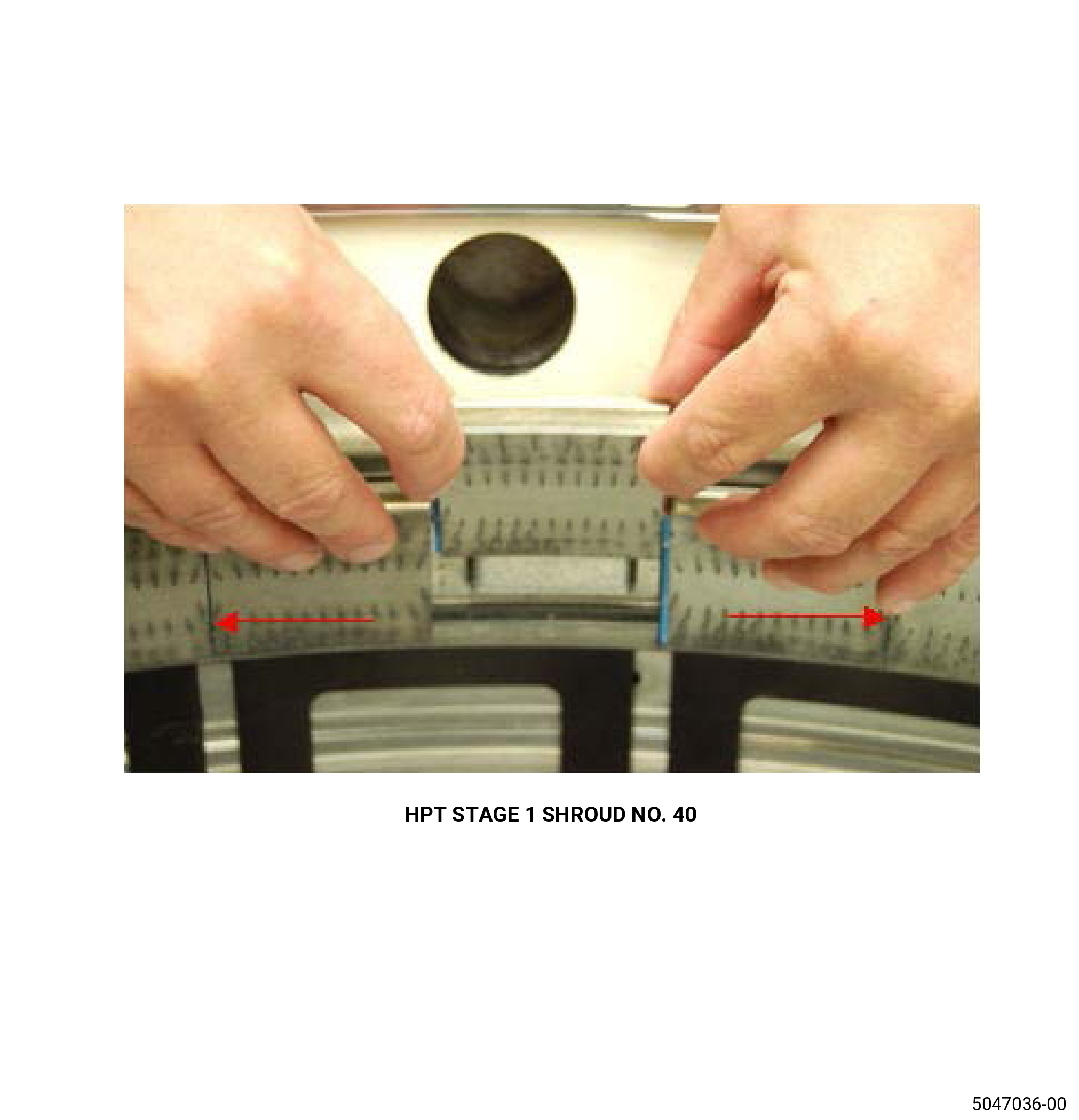
| (c) | Compress the shrouds to fit the shroud number 40 in place, taking care not to disengage the spline seals. Refer to Figure 1011. |
| (d) | Install shroud number 40. Engage all spline seals into slots, and engage all shroud slots with the hanger pin. Refer to Figure 1012. |
| (e) | Lift each shroud slightly and put the aft lip over the aft inner rail of the shroud hanger. |
| (f) | Make sure that the shrouds are engaged in the shroud hangers. If necessary, use a mallet to tap the shrouds up and radially outward until seated. |
| (g) | Install the 40 dummy C-clips (item 3) of the 11C4425 shroud hanger dummy C-clip with the arrows pointing outward. |
| (3) | Install each retaining clip (01-070) (SIN 17309) and (01-075) (SIN 1730A) on the shrouds and shroud hangers. Refer to Figure 1013 and do as follows: |
| WARNING: |
|
| CAUTION: |
|
| (a) | Apply a thin coating of C02-033 lubricant on the aft rails of the shroud hangers and shrouds. |
| (b) | Install the expander ring (item 11) of the 11C3143 hanger install fixture into the center of the shrouds until the upper lip touches the aft surface of the shrouds. |
| (c) | Turn the expander knob (item 5) until the expander ring (item 11) is tight against the inner diameter of the shrouds. |
| (d) | Remove the 40 dummy C-clips (item 3) of the 11C4425 shroud hanger dummy C-clip. |
| CAUTION: |
|
| (e) | Put a retaining clip on the aft rail of the shroud and shroud hanger, centered on the shroud. |
| (f) | Install the retaining clip with a nylon rod and a ball peen hammer. |
| (g) | Install one retaining clip (01-070) (SIN 17309) over 39 shrouds (01-091) (SIN 17300). Keep a consistent end clearance. |
| (h) | Install one retaining clip (01-075) (SIN 1730A) over the remaining shroud (01-091) (SIN 17300). |
| (i) | Leave the maximum possible clearance on one end of the shroud. This clearance is for disassembly purposes. |
| (j) | Make sure that each retaining clip is not beyond the end of the stage 1 shrouds and that the end clearances are consistent. |
| (k) | Make sure that the end clearance at the last location is not more than 0.140 inch (3.56 mm). |
|
|
|
| Subtask 72-52-00-440-090 |
| (4) | Turn the expander knob (item 5) to loosen the expander ring (item 11) and remove it. Refer to Figure 1013. |
| Subtask 72-52-00-220-055 |
| (5) | Do a shim check to make sure that the shroud hangers stay correctly installed in the HPT stator case. Refer to Figure 1013 and do as follows: |
| (a) | Use a 0.002 inch (0.05 mm) shim stock. |
| (b) | Make sure that the shim stock cannot go between the shroud hanger and the case. |
| (c) | Do the check near the ends of each shroud hanger. |
| Subtask 72-52-00-440-091 |
| (d) | If the shim check shows that one or more of the shroud hangers are not installed correctly, do the procedure that follows: |
| 1 | Turn the HPT stator case forward end up in the 11C3143 hanger install fixture. Refer to Subtask 72-52-00-440-084 (paragraph 3.C.). |
| 2 | Increase torque on the screws (item 23) of the hangers that are not completely seated to maximum 540 lb in (61 Nm). Refer to Figure 1006. |
| 3 | Turn the HPT stator case forward end down in the 11C3143 hanger install fixture. Refer to Subtask 72-52-00-440-086 (paragraph 3.D.(19)). |
| 4 | Do the shim check again. Refer to Subtask 72-52-00-220-055 (paragraph 3.E.(5)). |
| Subtask 72-52-00-440-092 |
| F. | Assemble the stage 2 nozzle and impingement ring assembly on the 11C3291 lift/install fixture as follows: |
| Subtask 72-52-00-440-093 |
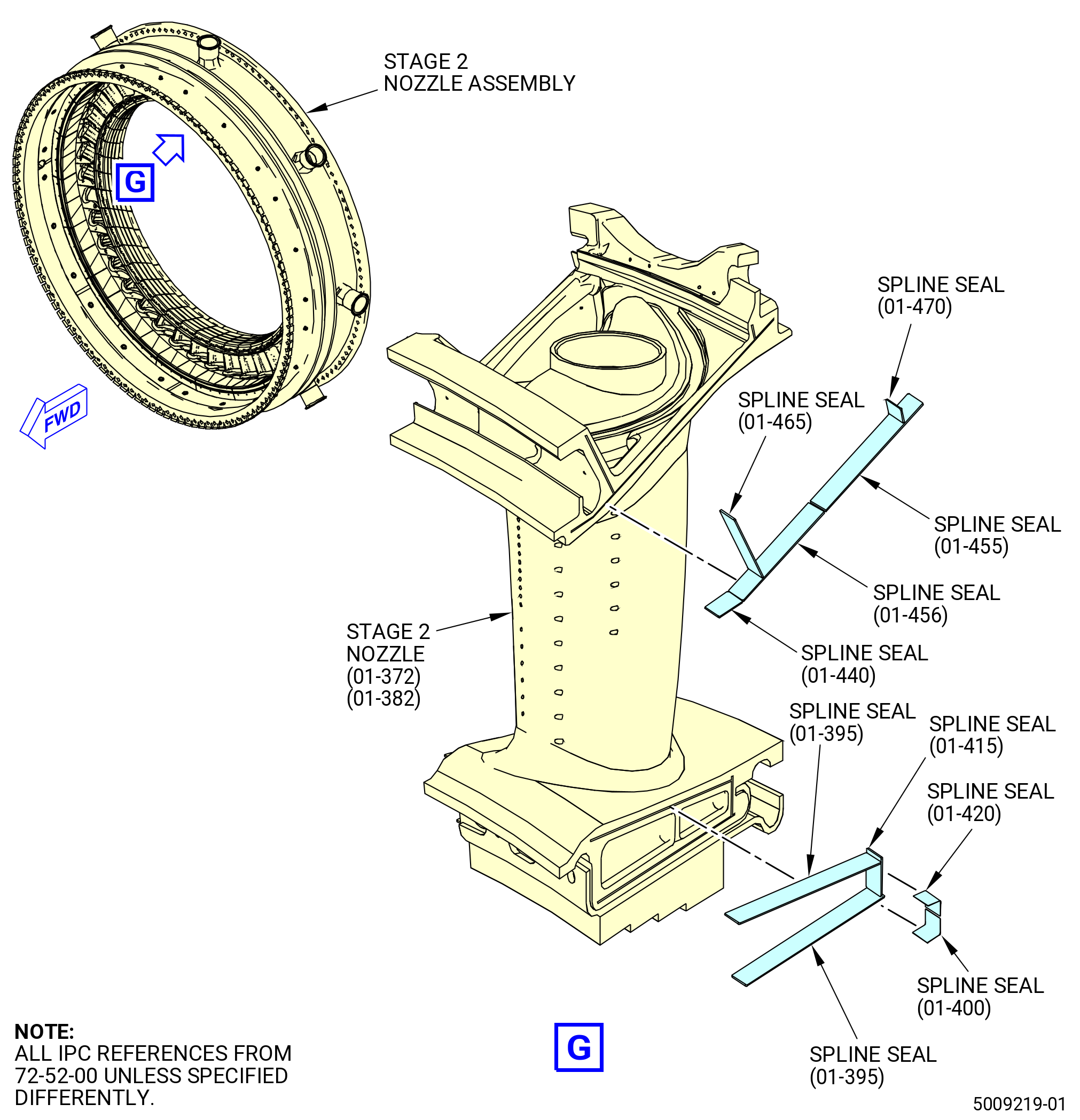
| (1) | Install spline seals in the stage 2 nozzle segments (nozzle segment) (01-372) (SIN 174A0) and (01-382) (SIN 174A1). Refer to Figure 1014 and do as follows: |
| (a) | Apply a small quantity of C10-154 beeswax, C10-109 utility wax, C02-033 lubricant, or C01-037 adhesive to the seal slots on the same end of each nozzle segment (01-372) (SIN 174A0) and (01-382) (SIN 174A1). |
| CAUTION: |
|
| (b) | Install the outer spline seals below in the side of each nozzle segment (01-372) (SIN 174A0) and (01-382) (SIN 174A1) that has beeswax, utility wax, lubricant, or adhesive. |
| • |
|
| • |
|
| • |
|
| • |
|
| • |
|
| (c) | Install the inner spline seals (01-415) (SIN 174WG) and (01-395) (SIN 174WF) in the side of each nozzle segment (01-372) (SIN 174A0) and (01-382) (SIN 174A1) that has beeswax, utility wax, lubricant, or adhesive. |
| (d) | Install the second set of inner spline seals (01-420) (SIN 174WB) and (01-400) (SIN 174WC) in the side of each nozzle segment (01-372) (SIN 174A0) and (01-382) (SIN 174A1) that has beeswax, utility wax, lubricant, or adhesive. |
| NOTE: |
|
| Subtask 72-52-00-440-094 |
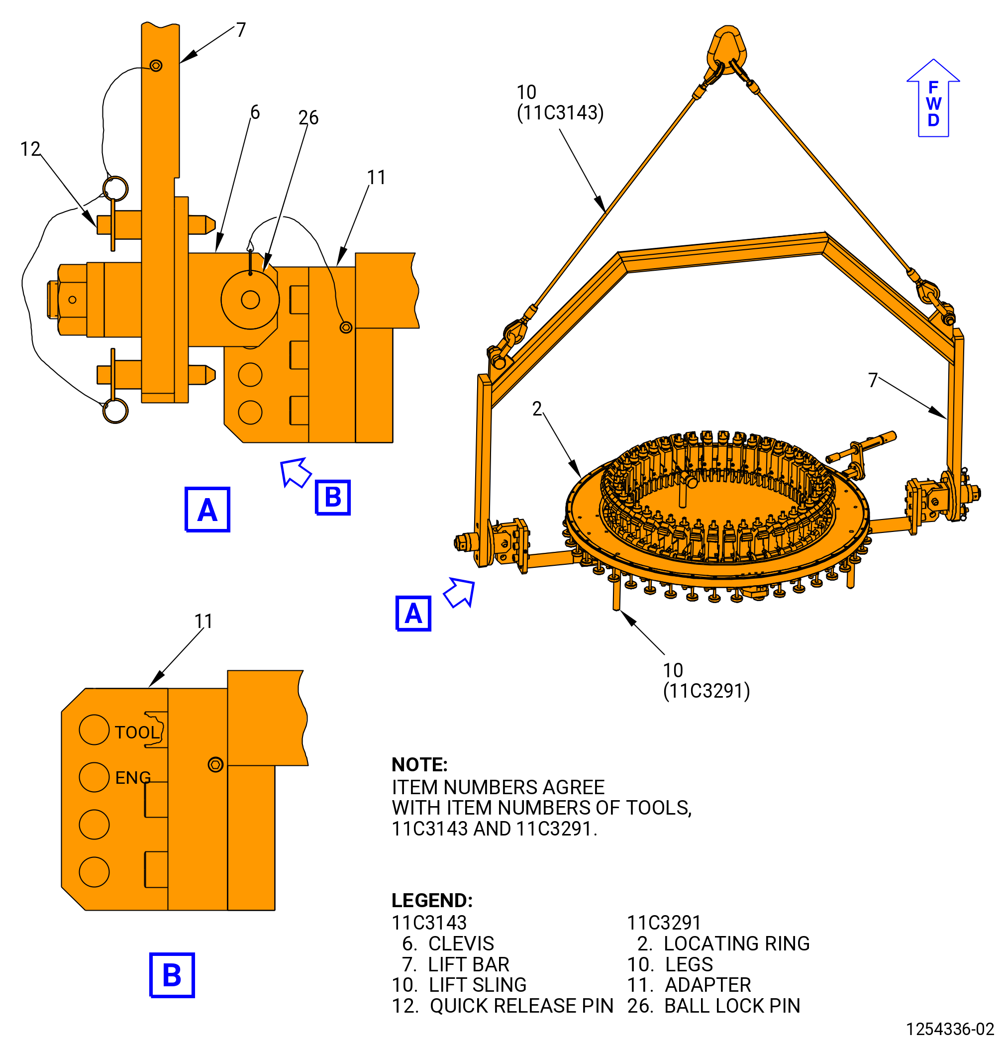
| (2) | If necessary, attach the ring legs (leg) (item 10) and put the 11C3291 lift/install fixture forward end up. Refer to Figure 1015 and do as follows: |
| WARNING: |
|
| (a) | Attach the lift sling (item 10) of the 11C3143 hanger install fixture to an overhead hoist. Lift the lift bar (item 7). |
| (b) | Lower the lift bar (item 7) to the adapter (item 11) of the 11C3291 lift/install fixture. |
| (c) | Attach the clevises (item 6) of the 11C3143 hanger install fixture to the adapter (item 11) of the 11C3291 lift/install fixture with the ball-lock pin (item 26) at the hole marked TOOL. |
| (d) | Make sure that the quick release pins (item 12) of the 11C3143 hanger install fixture are installed through the lift bar (item 7) and engaged in the plate of the clevises (item 6). |
| (e) | Lift the 11C3291 lift/install fixture. |
| (f) | Disengage the quick release pins (item 12) of the 11C3143 hanger install fixture. Turn the 11C3291 lift/install fixture forward end down. Engage the quick release pins (item 12) of the 11C3143 hanger install fixture. |
| (g) | Lower the 11C3291 lift/install fixture to a table. |
| (h) | Install the legs (item 10) in the base (item 2 or item 29). |
| (i) | Lift the 11C3291 lift/install fixture. |
| (j) | Disengage the quick release pins (item 12) of the 11C3143 hanger install fixture. Turn the 11C3291 lift/install fixture forward end up. Engage the quick release pins (item 12) of the 11C3143 hanger install fixture. |
| (k) | Lower the 11C3291 lift/install fixture to a table. |
| (l) | Remove the ball-lock pins (item 26) of the 11C3291 lift/install fixture from the clevises (item 6) of the 11C3143 hanger install fixture. Remove the lift bar (item 7) from the adapter (item 11) of the 11C3291 lift/install fixture. |
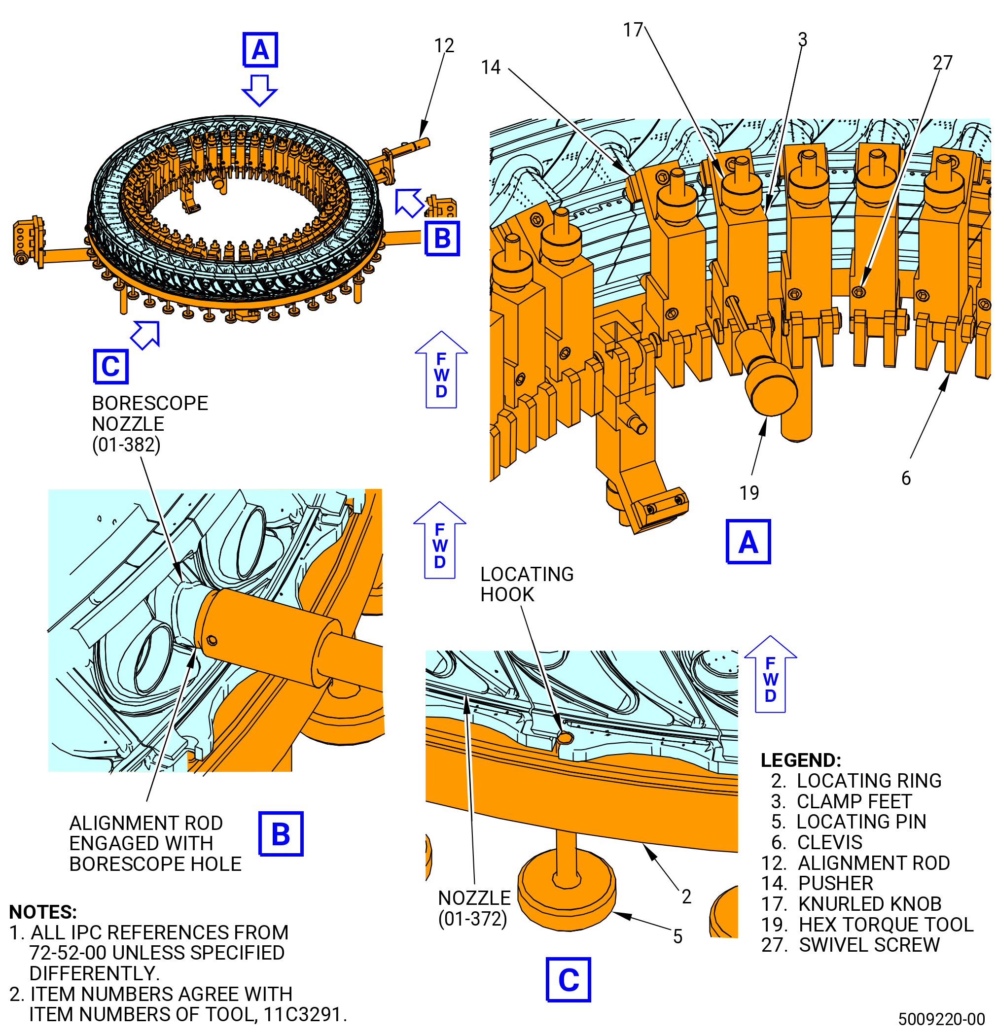
| (3) | Install the borescope nozzle segment (01-382) (SIN 174A1) on the 11C3291 lift/install fixture. Refer to Figure 1016 and do as follows: |
| (a) | Retract the locating pins (item 5) until the ends are below the top of the locating ring (item 2). |
| (b) | Retract the alignment rod (item 12). |
| (c) | Install the borescope nozzle segment aft side down at the alignment rod (item 12) position, on the locating ring (item 2). |
| CAUTION: |
|
| (d) | Turn the locating pin (item 5) at the borescope nozzle segment until it protrudes approximately 0.25 inch (6.4 mm) above the locating ring (item 2). |
| (e) | Put the locating hook in the aft outer ring of the borescope nozzle segment against the locating pin (item 5). |
| (f) | Engage the alignment rod (item 12) with the borescope hole in the nozzle segment to verify the position of the nozzle segment. |
| (4) | Install the remaining nozzle segments (01-372) (SIN 174A0) one at a time on the locating ring (item 2) as follows: |
| CAUTION: |
|
| (a) | Install a nozzle segment adjacent to one side of the borescope nozzle segment (01-382) (SIN 174A1) and engage the spline seals into the slots. |
| (b) | Install the next nozzle segment (01-372) (SIN 174A0) adjacent to the other side of the borescope nozzle segment (01-382) (SIN 174A1) and engage the spline seals into the slots. |
| (c) | Continue to install nozzle segments (01-372) (SIN 174A0), one at a time, on alternating sides of the borescope nozzle segment (01-382) (SIN 174A1) while engaging the spline seals into the slots until there is a space 180 degrees from the borescope nozzle segment. |
| (d) | Push the installed nozzle segments towards the borescope nozzle segment to make sufficient space for the last nozzle segment. |
| (e) | Install the last nozzle segment on the locating ring (item 2). |
| CAUTION: |
|
| (f) | Open the clearance between the nozzle segments as follows: |
| 1 | Begin with the nozzle segments on either side of the borescope nozzle. Carefully move each nozzle segment in small increments towards the nozzle segment. |
| 2 | As each nozzle segment is moved into position, turn the locating pin (item 5) until it protrudes approximately one quarter inch above the locating ring (item 2). |
| 3 | As the locating pins engage the hook in the aft outer ring of the nozzle segments, the nozzle segments will be evenly spaced. |
| (g) | Use a mirror, flashlight, and small pick to make sure that all the spline seals are correctly installed and engaged in the slots of the nozzle segments. |
| (h) | Lock the nozzle segments (01-372) (SIN 174A0) and (01-382) (SIN 174A1) in place on the 11C3291 lift/install fixture as follows: |
| 1 | Move the nozzle segments radially out to engage the rabbet in the locating ring (item 2). |
| 2 | Put the clamp feet (item 3) on top of the clevis (item 6). |
| 3 | Use a hex torque tool (item 19) to the tighten swivel screws (item 27) to attach firmly the nozzle segments against the rabbet in the locating ring (item 2). |
| 4 | Hand tighten the knurled knob (item 17) on the end of each clamp foot. |
| 5 | Use the hex torque tool (item 19) to put the pusher (item 14) against the inner band of each nozzle segment. |
| Subtask 72-52-00-220-056 |
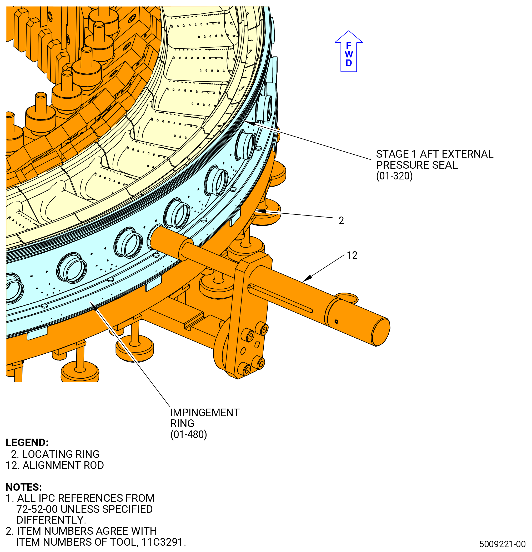
| (5) | Install the impingement ring (01-480) (SIN 174A9) on the nozzle segments with the 11C3291 lift/install fixture. Refer to Figure 1017 and do as follows: |
| (a) | Do an inspection of the air tube holes in the impingement ring for dents or out of round condition. |
| (b) | Retract the alignment rod (item 12) on the 11C3291 lift/install fixture. |
| (c) | Put the impingement ring on the 11C3291 lift/install fixture with the tabs down and align the borescope hole in the impingement ring with the borescope hole in the nozzle (01-382) (SIN 174A1). |
| (d) | Make sure that the impingement ring tabs are put outside and against the locating ring (item 2). |
| (e) | Make sure that the impingement ring is completely seated on the outer rabbet diameter of the locating ring (item 2). |
| (f) | Engage the alignment rod (item 12) with the borescope hole in the impingement ring to verify the position of the impingement ring. |
| Subtask 72-52-00-440-095 |
| (6) | Apply a small quantity of C10-154 beeswax, C10-109 utility wax, or C01-050 adhesive to some locations on the forward channel of the impingement ring. Refer to Figure 1017. |
| (7) | Install the stage 1 aft external pressure seal (01-320) (SIN 17351) in the forward channel of the impingement ring. |
| (8) | Make sure that the stage 1 aft external pressure seal (01-320) (SIN 17351) is correctly installed in the forward channel of the impingement ring. |
| Subtask 72-52-00-440-096 |
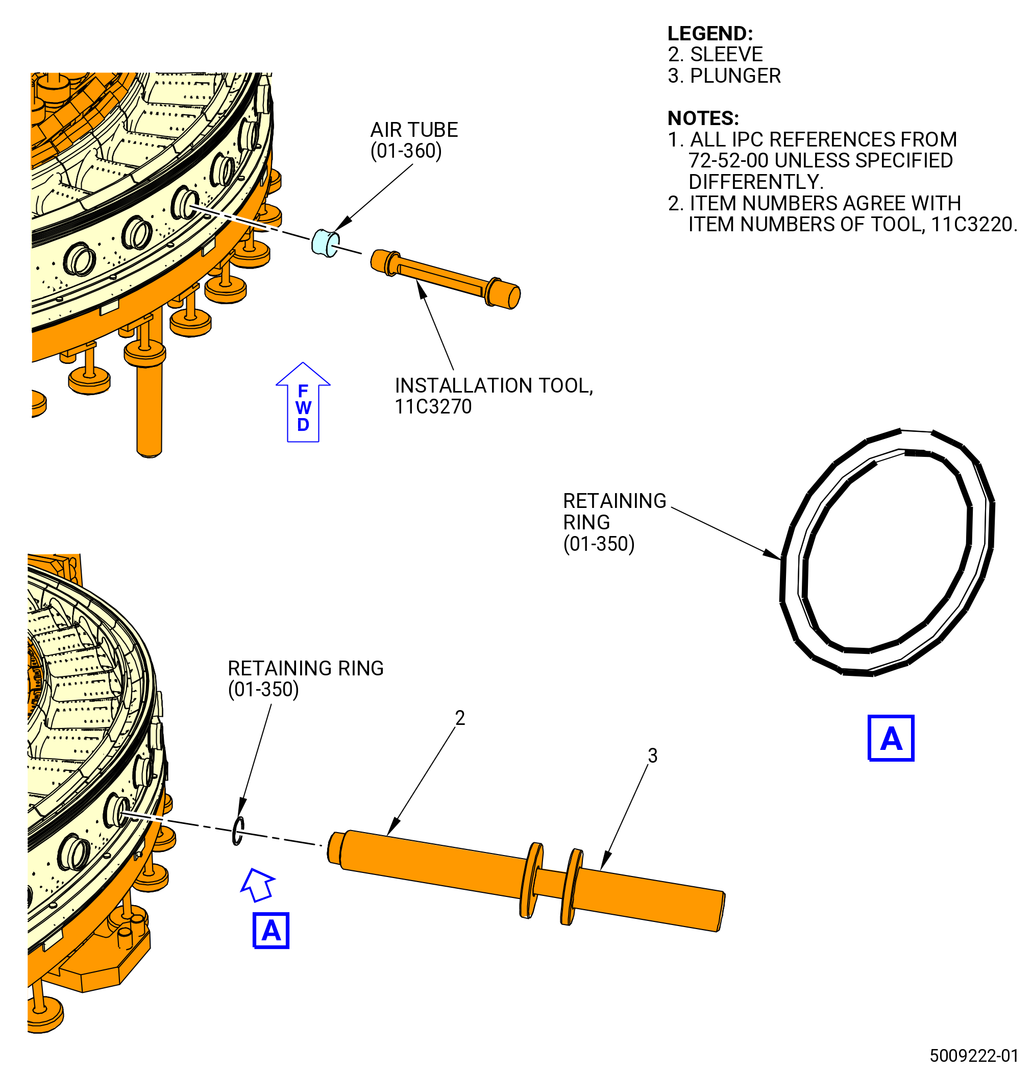
| G. | Install the cooling air tubes (01-360) (SIN 174A4) and retaining rings (01-350) (SIN 174WA) in the nozzle/impingement ring assembly. Refer to Figure 1018 and do as follows: |
| (1) | Align the hole for the cooling air tubes on the impingement ring (01-480) (SIN 174A9) and the nozzle segments (01-372) (SIN 174A0) and (01-382) (SIN 174A1) with the end of the 11C3270 installation tool marked ALIGNMENT. |
| CAUTION: |
|
| CAUTION: |
|
| NOTE: |
|
| (2) | Install the cooling air tubes (01-360) (SIN 174A4) as follows: |
| (a) | Put the cooling air tube on the end of the 11C3270 installation tool marked INSTALLATION. Make sure that the arrow on the cooling air tube points away from the tool handle. |
| NOTE: |
|
| (b) | Carefully insert the cooling air tubes in the impingement ring (01-480) (SIN 174A9). |
| (c) | Engage the cooling air tubes in each nozzle segment with the 11C3270 installation tool until they are just past the retaining ring groove in the impingement ring (01-480) (SIN 174A9). |
| Subtask 72-52-00-440-097 |
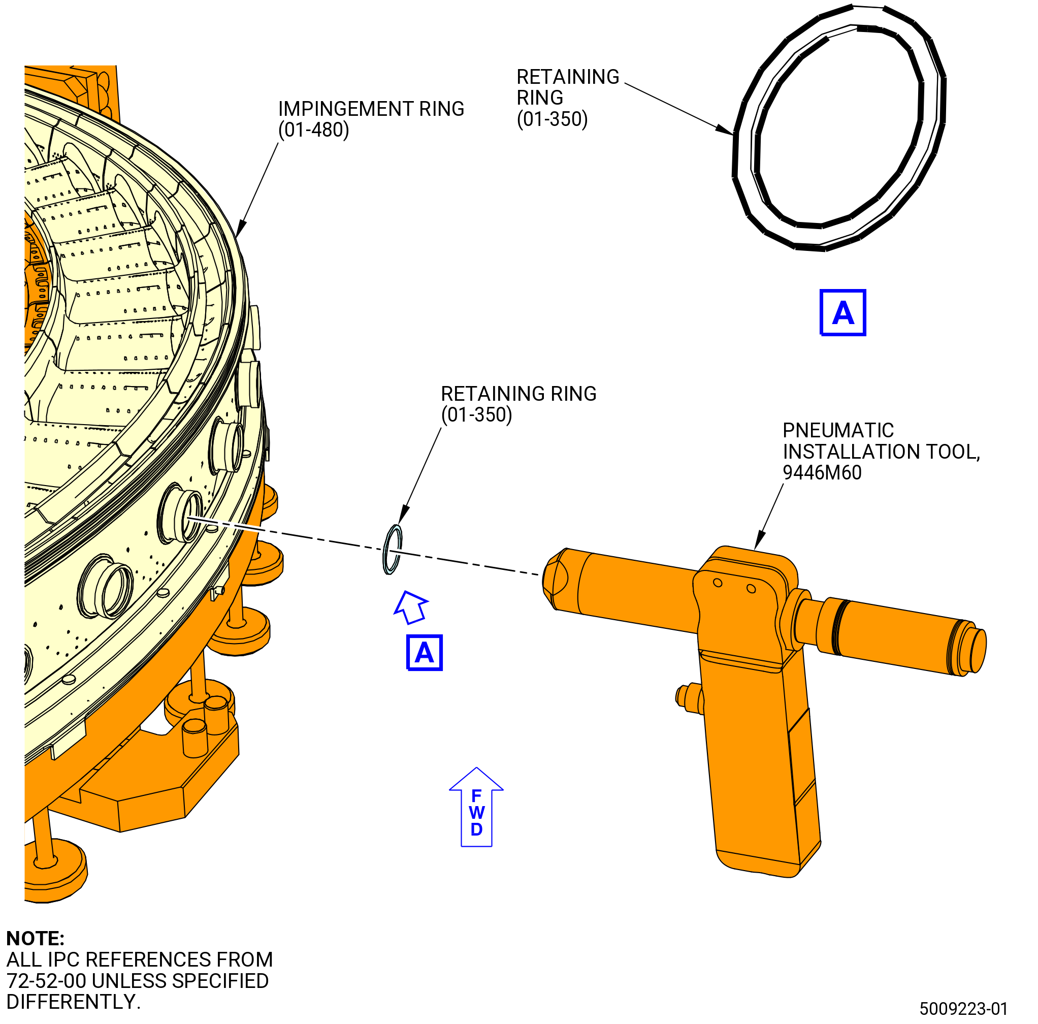
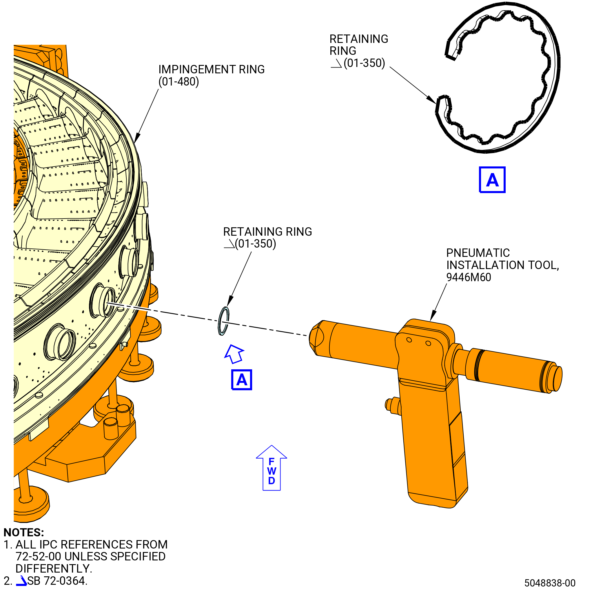
| (3) | Alternative Procedure Available. Install the retaining rings (01-350) (SIN 174WA) in the impingement ring (01-480) (SIN 174A9) with the 9446M60 pneumatic installation tool. Refer to Figure 1019 and do as follows: |
| (a) | Insert a retaining ring (01-350) (SIN 174WA) into the slot at the end of the 9446M60 pneumatic installation tool until it fully falls down into the end slot. |
| (b) | Put the 9446M60 pneumatic installation tool against the impingement ring (01-480) (SIN 174A9). |
| (c) | Make sure that the 9446M60 pneumatic installation tool is fully seated against the ring. |
| (d) | Fully push the trigger of the 9446M60 pneumatic installation tool to install the retaining ring (01-350) (SIN 174WA). |
| (e) | Remove the 9446M60 pneumatic installation tool from the impingement ring (01-480) (SIN 174A9). |
| (f) | Make sure that the retaining ring (01-350) (SIN 174WA) can turn freely and is fully engaged in the groove of the impingement ring (01-480) (SIN 174A9). |
| (g) | Use a mirror and a flashlight to make sure that all the spline seals are correctly installed. |
| Subtask 72-52-00-440-098 |
| (3).A. | Alternative Procedure. Install the retaining rings (01-350) (SIN 174WA) in the impingement ring (01-480) (SIN 174A9). Refer to Figure 1018 and do as follows: |
| (a) | Disconnect the plunger (item 3) from the sleeve (item 2) of the 11C3220 installation tool. |
| WARNING: |
|
| (b) | Apply a small quantity of C02-033 lubricant on the OD of the retaining ring (01-350) (SIN 174WA). |
| (c) | Insert the retaining ring (01-350) (SIN 174WA) into the large ID end of the sleeve (item 2). |
| (d) | Insert, but not fully, the plunger (item 3) into the large ID end of the sleeve (item 2). |
| (e) | Insert the small end of the sleeve (item 2) into the air tube hole and carefully push the plunger (item 3) to install the retaining ring (01-350) (SIN 174WA) into the groove in the impingement ring (01-480) (SIN 174A9). |
| (f) | Make sure that the retaining ring (01-350) (SIN 174WA) can turn freely and is fully engaged in the groove of the impingement ring (01-480) (SIN 174A9). |
| (g) | Use a mirror and a flashlight to make sure that all the spline seals are correctly installed. |
|
|
|
|
| Subtask 72-52-00-440-099 |
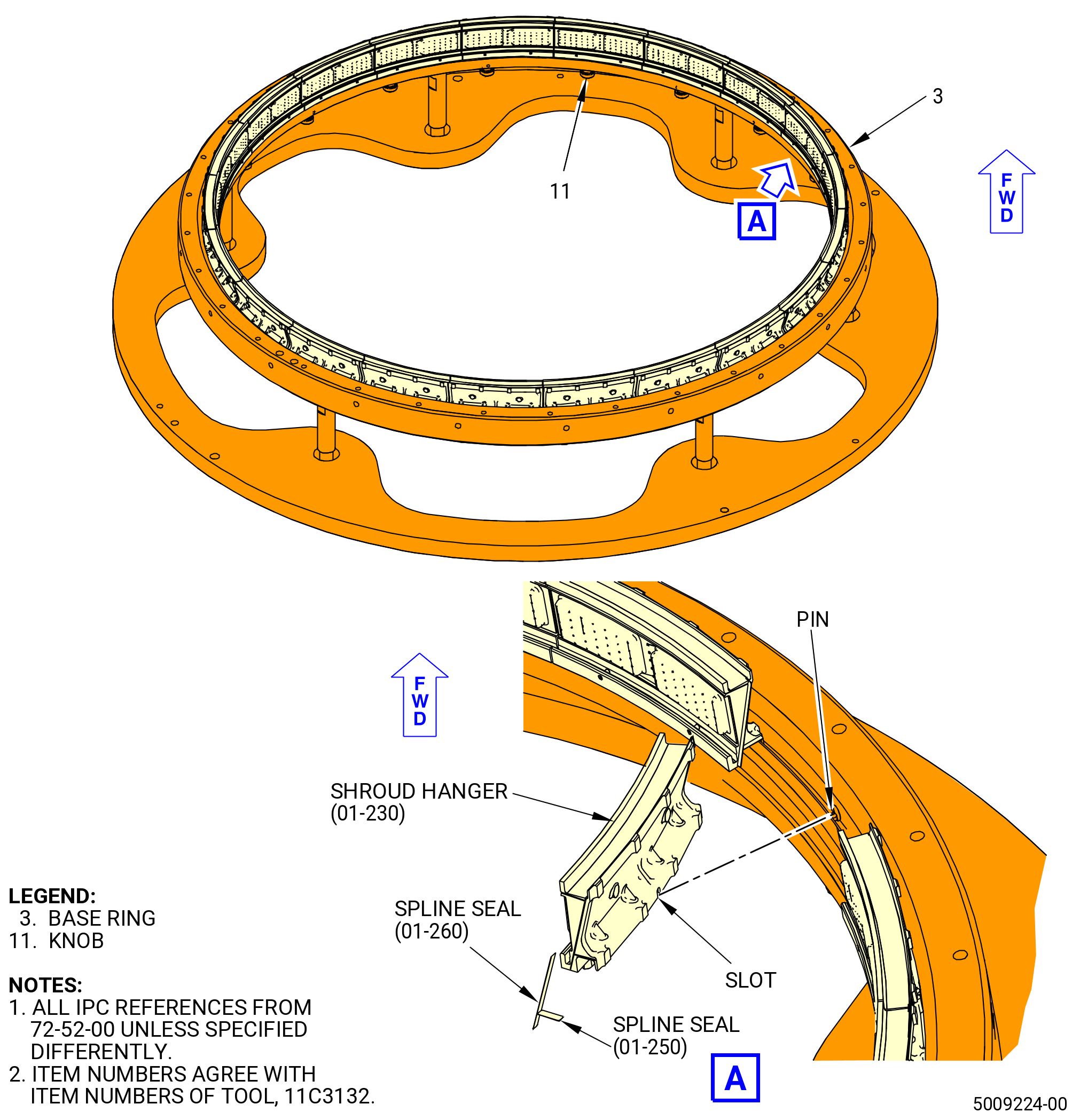
| H. | Assemble the HPT stator stage 2 hangers (shroud hangers) (01-230) (SIN 17801) on the 11C3132 stage 2 build fixture as follows: |
| (1) | Apply a small quantity of C10-154 beeswax, C10-109 utility wax, C02-033 lubricant, or C01-050 adhesive to the seal slots on the same end of each shroud hanger. Refer to Figure 1020. |
| NOTE: |
|
| (2) | Install the spline seals (01-260) (SIN 17802) and (01-250) (SIN 17807) in the waxed slots of each shroud hanger. |
| (3) | Make sure that the spline seals (01-260) (SIN 17802) and (01-250) (SIN 17807) are correctly installed in the waxed slots of each shroud hanger. |
| WARNING: |
|
| (4) | Apply C02-033 lubricant to the contact surfaces of the shroud hangers. |
| (5) | Loosen the knobs (item 11) to put the pin below the surface of the base ring (item 3). |
| (6) | Install the shroud hanger forward end down on the base ring (item 3), at the TOP mark. Align the slot in the forward outer rail with the pin of the knob (item 11). |
| (7) | Tighten the knob (item 11) to engage the pin in the slot of the shroud hanger. |
| (8) | Install the remaining shroud hangers as follows: |
| CAUTION: |
|
| (a) | Install a shroud hanger adjacent to one side of the installed shroud hanger and engage the spline seals into the slots. |
| (b) | Install the next shroud hanger adjacent to the other side of the installed shroud hanger and engage the spline seals into the slots. |
| (c) | Continue to install shroud hangers, one at a time, on alternating sides of the installed shroud hangers while engaging the spline seals until there is a space 180 degrees from the first shroud hanger. |
| (d) | Push the installed shroud hangers towards the first shroud hanger to make sufficient space for the last shroud hanger. |
| (e) | Install the last shroud hanger on the base ring (item 3). |
| (f) | Begin with the shroud hangers on either side of the first shroud hanger. Carefully move each shroud hanger in small increments towards the shroud hanger installed last, until the last spline seals are engaged. As each shroud hanger is moved, turn the knob (item 11) to engage the pin into the slot of each shroud hanger. As the pins engage the slot of each shroud hanger, the clearances will be evenly spaced. |
| (g) | Use a mirror, flashlight, and small pick to make sure that all the spline seals are correctly installed and engaged in the slots of the shroud hanger. |
| Subtask 72-52-00-440-100 |
| WARNING: |
|
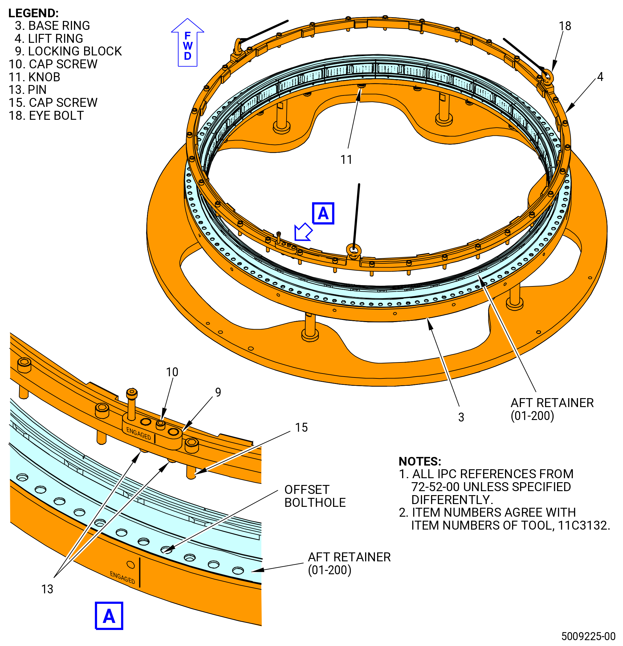
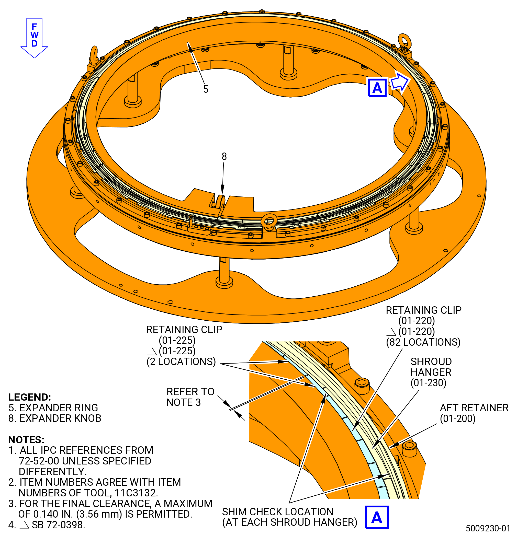
| (9) | Apply C02-033 lubricant on the aft side of the shroud hangers where the aft retainer (01-200) (SIN 17808) will be installed. Refer to Figure 1021. |
| (10) | Install the aft retainer (01-200) (SIN 17808) forward end down over the shroud hangers on the 11C3132 stage 2 build fixture. Align the offset boltholes in the aft retainer (01-200) (SIN 17808) with the offset holes in the stage 2 build fixture. |
| Subtask 72-52-00-440-101 |
| WARNING: |
|
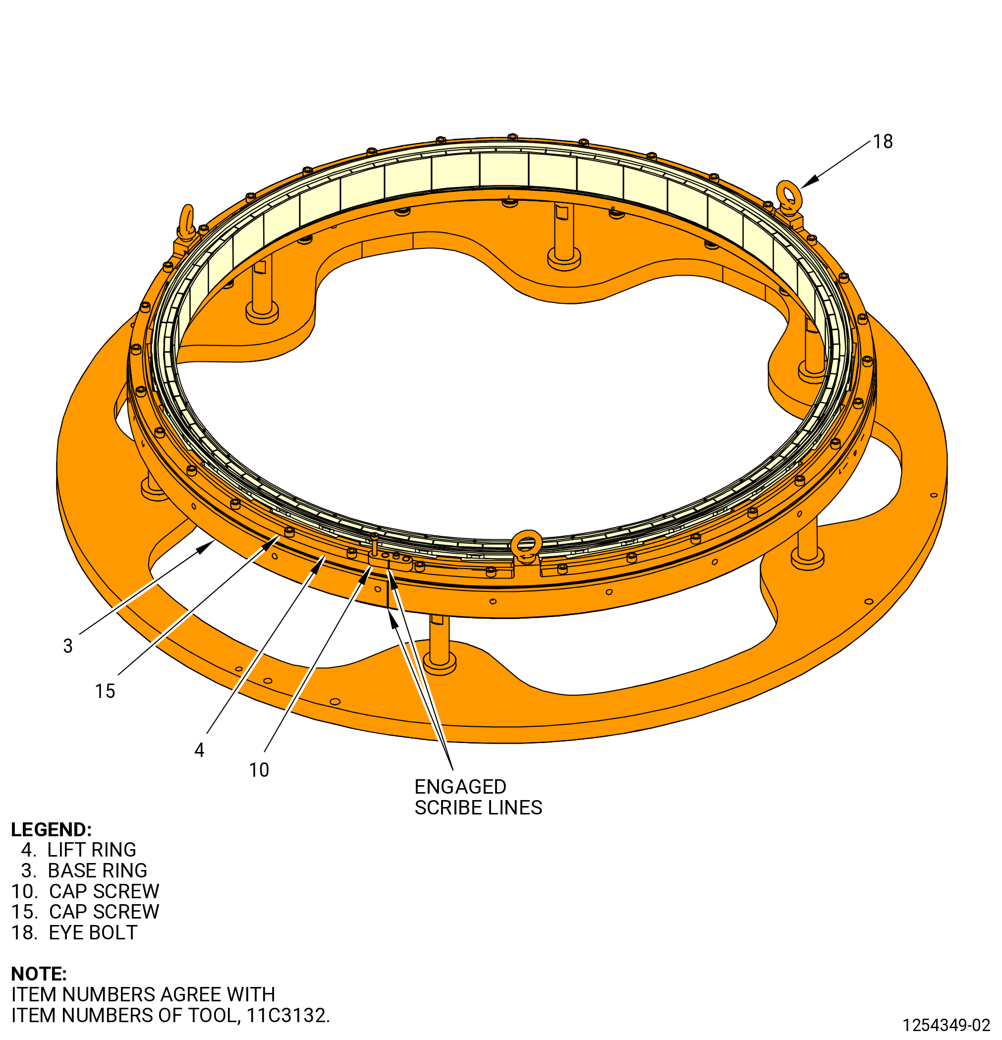
| (11) | Lift the lift ring (item 4) with a hoist and put it on the aft retainer, sliding the tabs on the lift ring between the tabs on the aft retainer. Make sure that the ENGAGED mark on the lift ring is near the ENGAGED mark on the base ring (item 3). |
| (12) | Turn the lift ring (item 4) to align the ENGAGED mark with the base ring (item 3) ENGAGED mark and align the offset holes in the lift ring (item 4) with the offset holes in the base ring (item 3). |
| (13) | Attach firmly the locking block (item 9) to the lift ring (item 4) with the capscrews (item 10). |
| (14) | Install the capscrews (item 15) hand-tight. |
| (15) | Torque eight equally spaced capscrews (item 15) sequentially, in one half turn increments, to 70 lb in. (7.9 N.m). |
| (16) | Torque all capscrews (item 15) in a criss-cross pattern to 70 lb in. (7.9 N.m). |
| (17) | Loosen the knobs (item 11) to disengage the pin from the shroud hanger. |
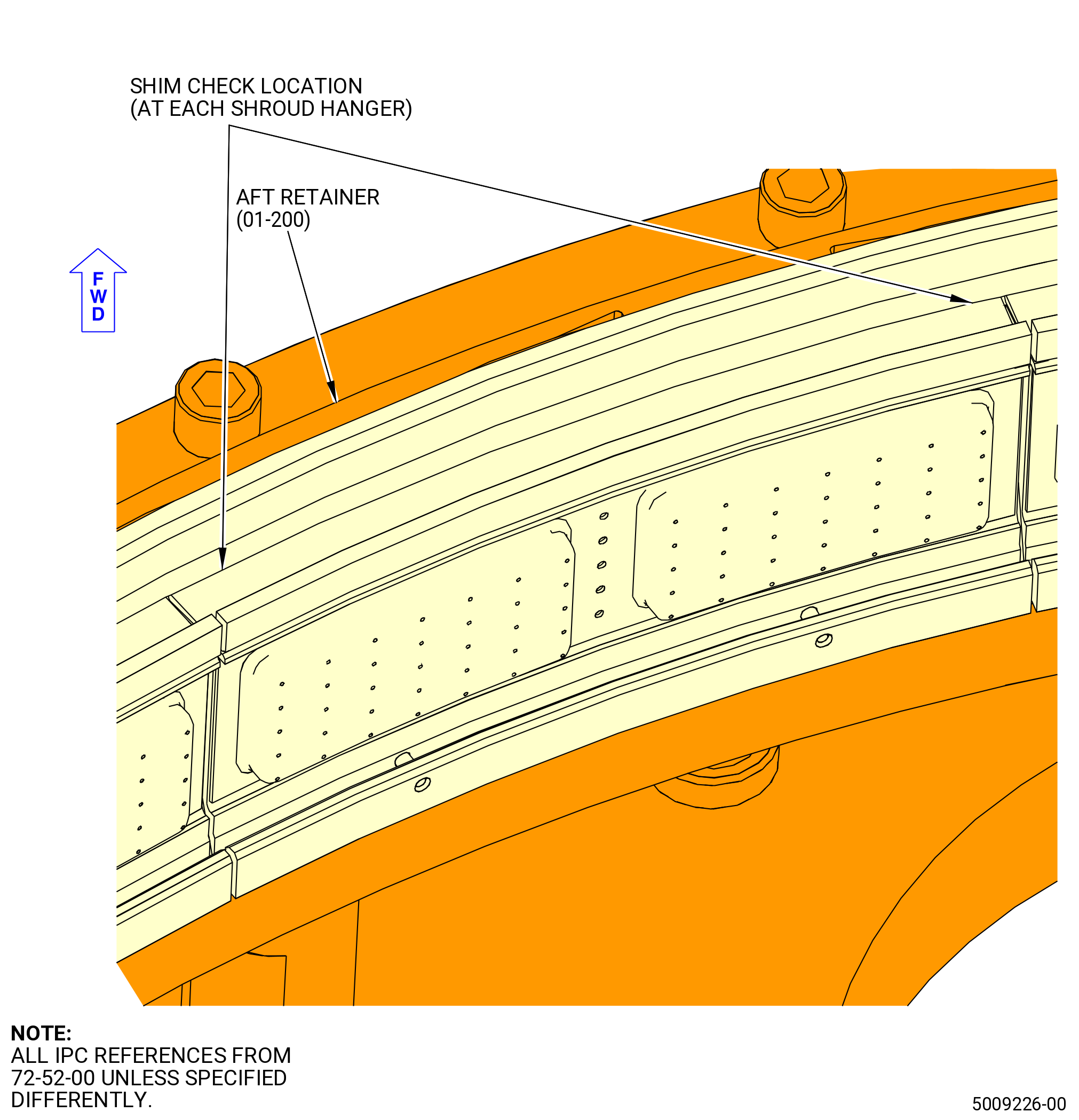
| (18) | Make sure that the aft retainer (01-200) (SIN 17808) is installed correctly on the shroud hangers. Refer to Figure 1022 and do as follows: |
| (a) | Use a 0.002 inch (0.05 mm) shim stock. |
| (b) | Make sure that the shim stock cannot go between the shroud hanger and the aft retainer. |
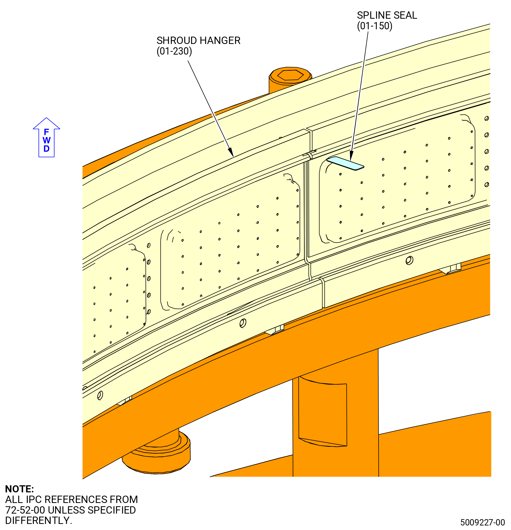
| (c) | Do the check near the ends of each shroud hanger. |
| (19) | Apply a small quantity of C10-154 beeswax, C10-109 utility wax, C02-033 lubricant, or C01-050 adhesive to the spline seals (01-270) (SIN 17803). Refer to Figure 1023. |
| (20) | Push the spline seals (01-270) (SIN 17803) into the slots between each shroud hanger (01-230) (SIN 17801) until they are fully installed. |
| Subtask 72-52-00-440-102 |
| (21) | Install the external pressure seal (01-310) (SIN 17852). Refer to Figure 1024 and do as follows: |
| WARNING: |
|
| (a) | Apply a small quantity of C01-037 adhesive to the external pressure seal groove on the shroud hangers with a hypodermic syringe. |
| (b) | Let the adhesive air dry until tacky. |
| CAUTION: |
|
| (c) | Install the external pressure seal (01-310) (SIN 17852) in the shroud hangers as follows: |
| 1 | Put the ends of the pressure seal within 0.50 inch (12.7 mm) of the centerline of the stage 2 shrouds. |
| 2 | Make sure that the end clearance between the ends of the pressure seal is 0.020 inch (0.51 mm) or less. |
| 3 | Make sure that the ends do not overlap. |
| NOTE: |
|
| (d) | Remove excessive adhesive from outside of the shroud hanger groove. |
| Subtask 72-52-00-440-103 |
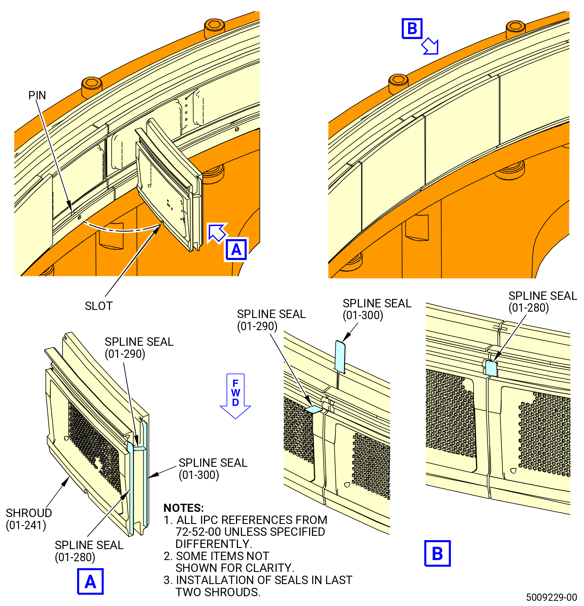
| I. | Assemble the HPT stage 2 shrouds (shrouds) (01-241) (SIN 17800) on the shroud hangers (01-230) (SIN 17801). Refer to Figure 1025 and do as follows: |
| (1) | Apply a small quantity of C10-154 beeswax, C10-109 utility wax, C02-033 lubricant, or C01-050 adhesive to the seal slots on the same end of each shroud. |
| NOTE: |
|
| (2) | Install the spline seals (01-280) (SIN 17804), (01-290) (SIN 17805), and (01-300) (SIN 17806) in the waxed end of 40 of the 42 shrouds. |
| NOTE: |
|
| CAUTION: |
|
| (3) | Put the stage 2 shrouds that have spline seals on the shroud hangers. Make sure that the pins on the shroud hangers are engaged in the slots of the shrouds. |
| (4) | Install the last two stage 2 shrouds. |
| (5) | Install the spline seals (01-280) (SIN 17804), (01-290) (SIN 17805), and (01-300) (SIN 17806) in the last two stage 2 shrouds in the correct sequence as follows: |
| (a) | Install the spline seals (01-300) (SIN 17806) until they are fully engaged in the seal slots. |
| (b) | Install the spline seals (01-290) (SIN 17805) until they are fully engaged in the seal slots. |
| (c) | Install the spline seals (01-280) (SIN 17804) until they are fully engaged in the seal slots. |
| CAUTION: |
|
| (6) | Manually lift the shrouds up and radially outward to engage the aft lip of the shrouds with the aft rail of the shroud hanger. If necessary, use a small plastic mallet to tap the shrouds up and radially outward. |
| (7) | Install the 42 dummy C-clips (item 3) of the 11C4425 shroud hanger dummy C-clip with the arrows pointing inward. |
| (8) | Install the expander ring (item 5) into the center of the shrouds with the lip seated against the aft edge and the outer face pressing against the shroud face. |
| (9) | Rotate the expander knob (item 11) to press the expander ring (item 5) firmly against the inner diameter of the shrouds. |
| (10) | Remove the 42 dummy C-clips (item 3) of the 11C4425 shroud hanger dummy C-clip. |
| WARNING: |
|
| CAUTION: |
|
| (11) | Apply a thin coating of C02-033 lubricant to the aft surfaces where the shroud and shroud hanger engage. Refer to Figure 1026. |
| (12) | Put one stage 2 retaining clip (01-220) (SIN 1780A) on each end of a shroud. Install the retaining clips with a nylon bar and mallet to engage the shroud and shroud hanger. Do not let the ends of the retaining clip extend more than the ends of the stage 2 shrouds. Make sure to keep an even end clearance between adjacent retaining clips. |
| CAUTION: |
|
| (13) | Install two stage 2 retaining clips (01-220) (SIN 1780A) over 41 shrouds (01-241) (SIN 17800). Keep a consistent end clearance. |
| (14) | Install two stage 2 retaining clips (01-225) (SIN 1780B) over the remaining shroud (01-241) (SIN 17800). Make sure to leave the maximum possible clearance in the middle of the shroud but not more than 0.140 inch (3.56 mm). |
| Subtask 72-52-00-440-104 |
| (15) | Make sure that each retaining clip is not beyond the end of the shrouds and that the end clearances are consistent. |
| (16) | Turn the expander knob (item 11) to loosen the expander ring (item 5) and remove the expander ring from the stage 2 shrouds. |
| Subtask 72-52-00-220-057 |
| (17) | Make sure that the aft retainer (01-200) (SIN 17808) is installed correctly on the shroud hangers. Refer to Figure 1022 and do as follows: |
| (a) | Use a 0.002 inch (0.05 mm) shim stock. |
| (b) | Make sure that the shim stock cannot go between the shroud hanger and the aft retainer. |
| (c) | Do the check near the ends of each shroud hanger. |
| Subtask 72-52-00-440-105 |
| J. | Install the nozzle/impingement ring assembly in the HPT stator case (01-490) (SIN 174B0) with the 11C3291 lift/install fixture and the 11C3143 hanger install fixture as follows: |
| Subtask 72-52-00-440-106 |
| WARNING: |
|
| (1) | Attach the lift sling (item 10) of the 11C3143 hanger install fixture to an overhead hoist. Lift the lift bar (item 7). Refer to Figure 1015. |
| (2) | Attach the lift bar (item 7) of the 11C3143 hanger install fixture to the adapters (item 11) of the 11C3291 lift/install fixture with the ball lock pins (item 26). |
| (3) | Install the ball lock pins (item 26) through the hole marked ENG in each adapter (item 11). |
| (4) | Make sure that the quick release pins (item 12) are engaged in the lift bar (item 7). |
| WARNING: |
|
| (5) | Lift the nozzle/impingement ring assembly in the 11C3291 lift/install fixture with the hoist. |
| WARNING: |
|
| (6) | Remove the quick release pins (item 12) of the 11C3143 hanger install fixture. |
| (7) | Turn the nozzle/impingement ring assembly until the stage 2 nozzles are facing down. |
| (8) | Install the quick release pins (item 12) of the 11C3143 hanger install fixture. |
| (9) | Align the borescope hole in the nozzle/impingement ring assembly with the borescope hole in the HPT stator case and the pins in the alignment plate (item 16) with the offset holes in the HPT case flange. Refer to Figure 1027. |
| (10) | Lower the nozzle/impingement ring assembly into the HPT stator case engaging the alignment pins in the alignment plate (item 16) in the offset holes in the HPT case flange. |
| CAUTION: |
|
| (11) | Use a nylon mallet to gently tap the 11C3291 lift/install fixture to engage the nozzle/impingement ring assembly in the HPT stator case. |
| (12) | Use the alignment rod (item 12) to make sure that the borescope hole in HPT case and nozzle/impingement ring assembly are aligned. |
| (13) | Remove the 11C3291 lift/install fixture from the nozzle/impingement ring assembly. Refer to Figure 1027 and do as follows: |
| CAUTION: |
|
| (a) | Use the hex torque tool (item 19) to retract the swivel screws (item 27). |
| (b) | Loosen the knobs (item 17) of the clamp feet (item 3). Put the clamp feet (item 3) on top of the clamp clevis (item 6) and tighten the knobs (item 17) to attach it firmly in place. |
| (c) | Retract the alignment rod (item 12) from the borescope hole in the HPT case. |
| (d) | With a hoist, carefully lift the 11C3291 lift/install fixture out of the nozzle/impingement ring assembly. |
| Subtask 72-52-00-220-058 |
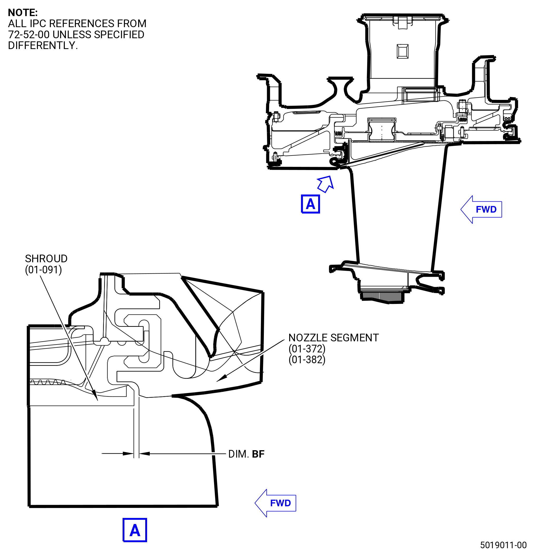
| (14) | Find dimension BF as follows: |
| (a) | Measure the distance from the aft surface of the shroud (01-091) (SIN 17300) to the forward lip of the nozzle segments (01-372) (SIN 174A0) and (01-382) (SIN 174A1) at seven equally spaced locations. Refer to Figure 1028. |
| (b) | Make a record of the distance as dimension BF. Make sure that dimension BF is between 0.045 inch (1.14 mm) and 0.025 inch (0.64 mm) at each of the seven locations. |
| Subtask 72-52-00-220-059 |
| CAUTION: |
|
| (15) | If there is more than one nozzle segment with missing aft mounting hooks, make sure that the nozzle segments with missing aft mounting hooks are equally spaced in the assembly. |
| Subtask 72-52-00-440-107 |
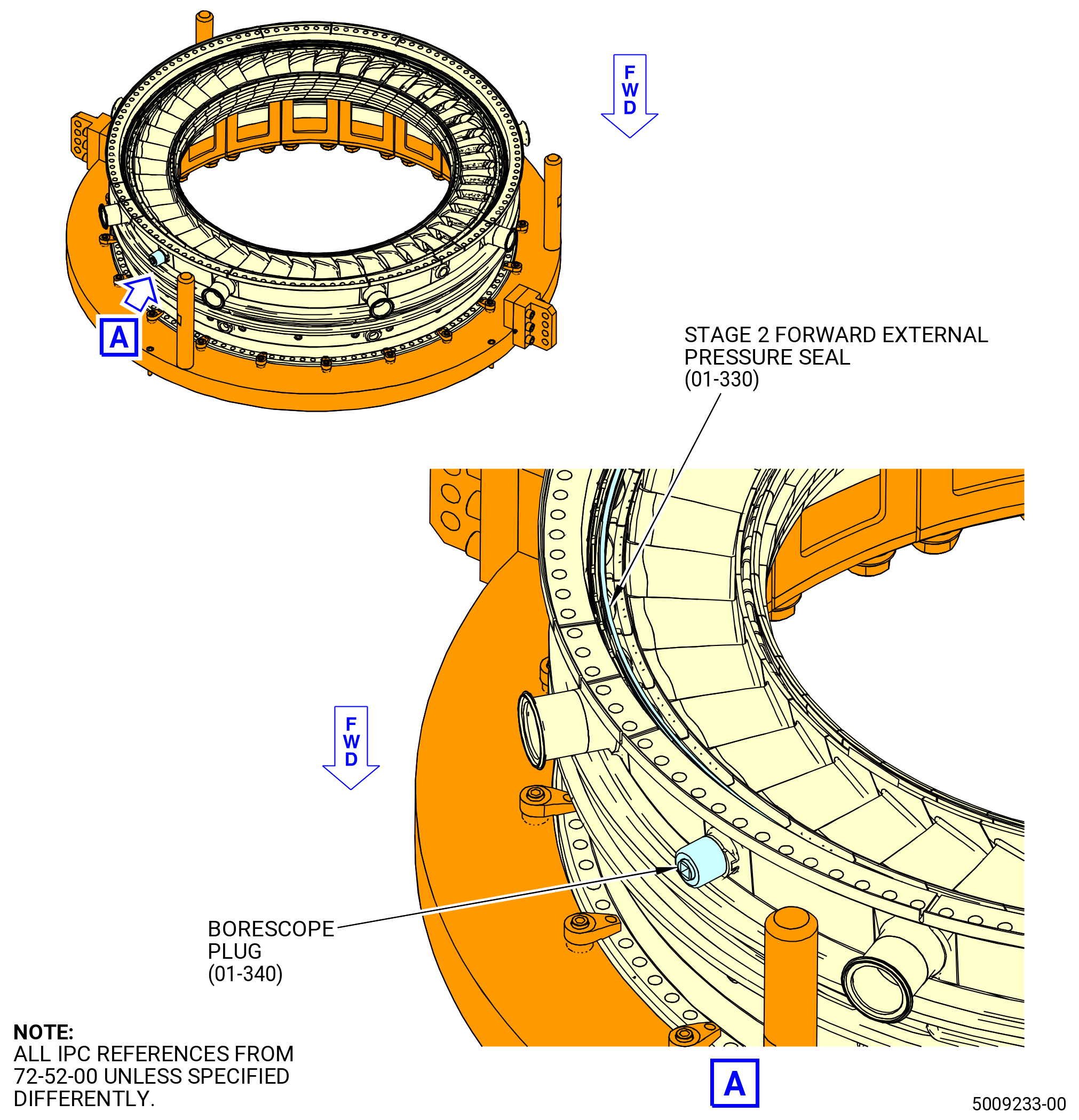
| K. | Install the stage 2 forward external pressure seal (01-330) (SIN 17851) on the aft side of the impingement ring (01-480) (SIN 174A9). Refer to Figure 1029 and do as follows: |
| WARNING: |
|
| (1) | Apply C10-154 beeswax, C10-109 utility wax, C02-033 lubricant, or C01-037 adhesive to the aft side of the impingement ring. |
| (2) | Install the forward external pressure seal on the aft side of the impingement ring. |
| Subtask 72-52-00-440-108 |
| L. | Install the stage 2 shroud assembly in the HPT stator case (01-490) (SIN 174B0) with the 11C3132 stage 2 build fixture as follows: |
| Subtask 72-52-00-440-109 |
| (1) | Remove the capscrews (item 15) from the lift ring (item 4) on the 11C3132 stage 2 build fixture. Refer to Figure 1032. |
| (2) | Make sure that the screw (item 10) is still tight and the ENGAGED marks are still aligned. |
| (3) | Attach a three-legged lift sling to the eyebolts (item 18). |
| WARNING: |
|
| (4) | Lift and install the stage 2 shroud assembly on the HPT stator case as follows: |
| (a) | Lift the stage 2 shroud assembly away from the 11C3132 stage 2 build fixture. |
| (b) | Apply C10-154 beeswax, C10-109 utility wax, or C01-037 adhesive to the aft retainer and/or heat shield. |
| (c) | Let C10-154 beeswax, C10-109 utility wax, or C01-037 adhesive air dry until tacky (approximately five minutes). |
| (d) | Install the heat shield (01-210) (SIN 173A7) on the stage 2 shroud assembly. Refer to Figure 1033 and do as follows: |
| 1 | Install the heat shield (01-210) (SIN 173A7) on the stage 2 shroud assembly under the aft retainer (01-200) (SIN 17808). |
| 2 | The ends of the heat shield overlap and the end with the step is located outward. |
| 3 | The small lip is positioned down and rests on the lands of the stage 2 shroud hangers. |
| (e) | Position the stage 2 shroud assembly over the HPT stator case and align the alignment pins (item 13) in the locking block (item 9) with the offset holes in the HPT stator case. |
| CAUTION: |
|
| (f) | Lower the stage 2 shroud assembly onto the HPT stator case and engage the alignment pins of the locking block (item 9) with the offset holes in the HPT stator case. |
| (g) | Align the feet of the shroud hangers with the locating hooks of the stage 2 nozzles (01-372) (SIN 174A0), (01-382) (SIN 174A1). |
| (h) | Align the slots in the shroud hangers with the pins in the HPT stator case hook rail. |
| (i) | Make sure that the shroud hangers (01-230) (SIN 17801) are fully engaged in the rail of the HPT stator case. |
| (5) | Install the six nutplates (item 6) below the forward face of the aft HPT case flange with the capscrews (item 15) hand-tight. Refer to Figure 1034. |
| (6) | Remove the lift sling from the eyebolts (item 18) of the 11C3132 stage 2 build fixture. |
| (7) | Torque the capscrews (item 15) in a criss-cross pattern to 100 lb in. (11.3 N.m). |
| (8) | Torque the capscrews (item 15) again in a criss-cross pattern to 200 lb in. (22.6 N.m). |
| (9) | Use a 0.002 inch (0.05 mm) shim stock to make sure that the aft retainer (01-200) (SIN 17808) is fully against the shroud hanger (01-230) (SIN 17801). |
| (10) | Remove the capscrews (item 15) and nutplates (item 6). |
| (11) | Attach a three-legged lift sling to the eyebolts (item 18). |
| (12) | Lift the lift ring (item 4) away from the stage 2 nozzle assembly. |
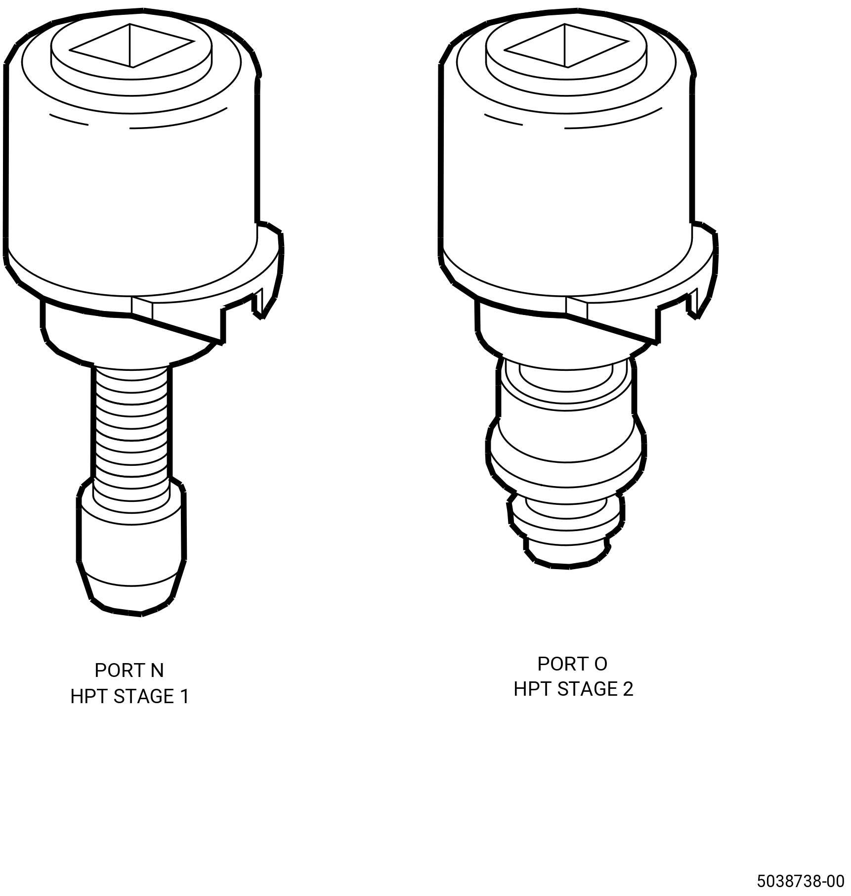
| Subtask 72-52-00-220-088 |
| (13) | Do a visual inspection of the borescope plugs and ports. Refer to TASK 72-00-00-800-804 (72-00-00, SPECIAL PROCEDURE 004) (paragraph 5.A. and 5.B.) and Figure 1030. |
| Subtask 72-52-00-440-110 |
| WARNING: |
|
| (14) | Apply C02-071 lubricant or C02-097 lubricant to the threads of the borescope plug (01-340) (SIN 17490). Refer to Figure 1029. |
| NOTE: |
|
| NOTE: |
|
| NOTE: |
|
| (15) | Install the borescope plug (01-340) (SIN 17490) in the HPT stator case at the 10:00 o'clock position ALF. Make sure that there is a minimum run-on torque of 15 lb in. (1.7 N.m). Replace the plug if the run-on torque is less than 15 lb in. (1.7 N.m). |
| (16) | Torque the borescope plug (01-340) (SIN 17490) to 142.6 to 167.4 lb in. (16.1 to 18.9 Nm). |
| (17) | Break torque on the borescope plug (01-340) (SIN 17490) and apply torque again to 142.6 to 167.4 lb in. (16.1 to 18.9 Nm). |
| (18) | After the plug has been torqued, perform a visual inspection of the plug and make sure that the locking feature is fully engaged with the lug on the borescope boss. Also make sure that the head of the borescope plug is fully seated against the borescope boss. If one of the two conditions are not met, the ratcheting feature of the plug can be seized or locked. Apply a penetrating oil directly in between the locking ring and the head of the plug. Re-apply torque to the plug until the plug begins to rotate freely. Tighten the plug from 142.6 to 167.4 lb in. (16.1 to 18.9 Nm). Do the visual inspection again before proceeding. If the conditions above cannot be met, replace the plug. Refer to Figure 1031. |
| Subtask 72-52-00-320-016 |
| M. | Machine the stage 2 nozzle assembly to the necessary dimensions as follows: |
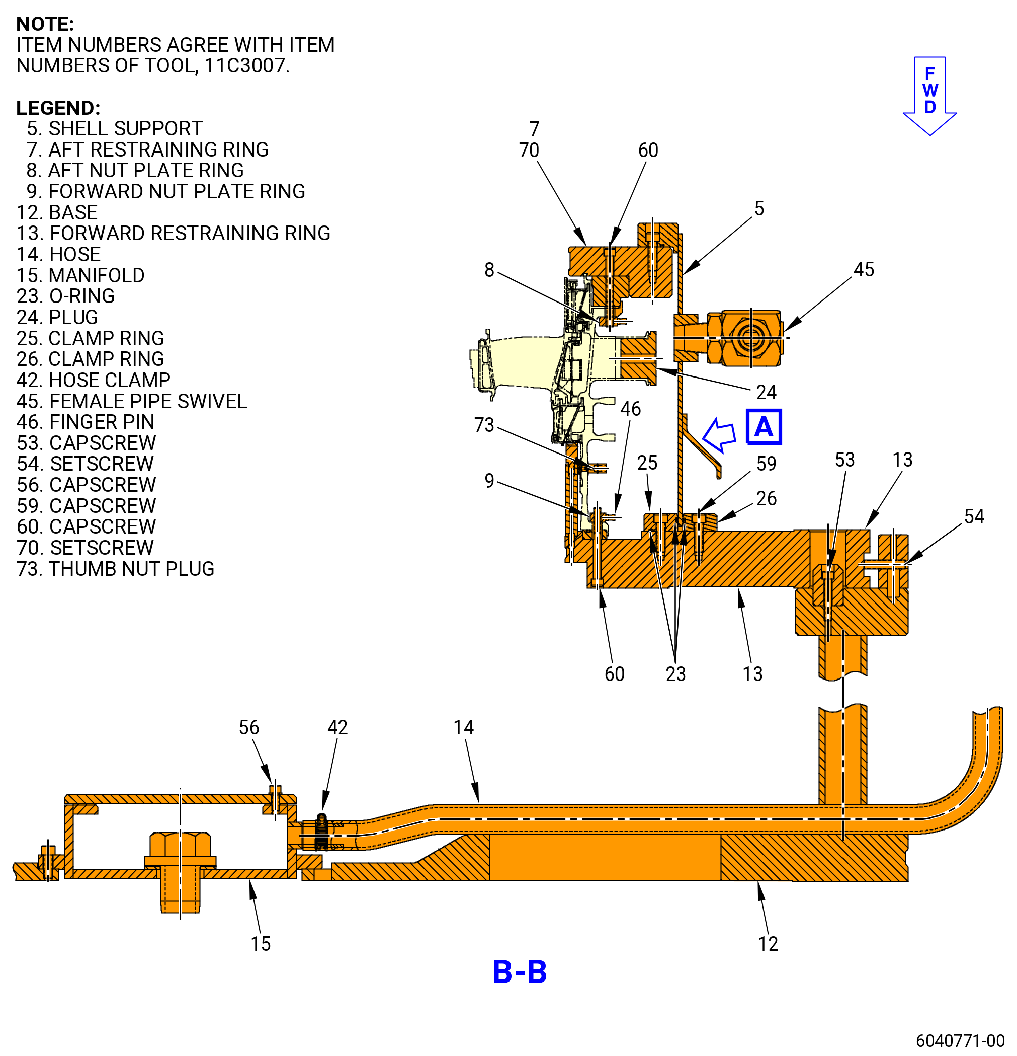
| (1) | Install the base (item 12) of the 11C3007 shroud grind fixture. Refer to Figure 1035 and do as follows: |
| WARNING: |
|
| (a) | Put the base (item 12) on the grind table with a hoist and lift sling. |
| (b) | Attach the base (item 12) to the grind table. Refer to the grind machine manufacturer's instructions. |
| (c) | Make sure that the base (item 12) is centered on the grind table to 0.001 inch (0.03 mm). |
| (d) | Make sure that there is no high metal on the base (item 12) flange. Refer to TASK 70-42-00-350-002 (BLENDING AND REMOVAL OF HIGH METAL PROCEDURES). |
| WARNING: |
|
| (e) | Clean the flange with C04-035 isopropyl alcohol. |
| Subtask 72-52-00-220-060 |
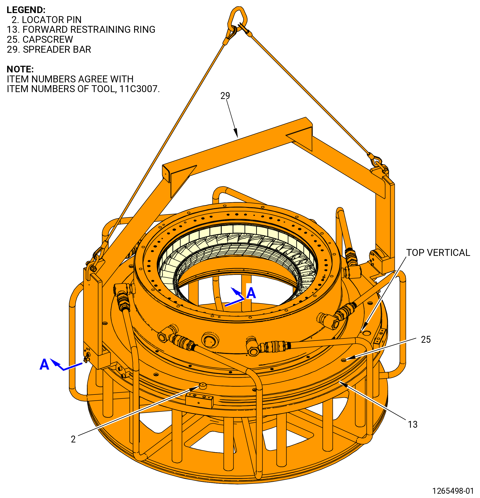
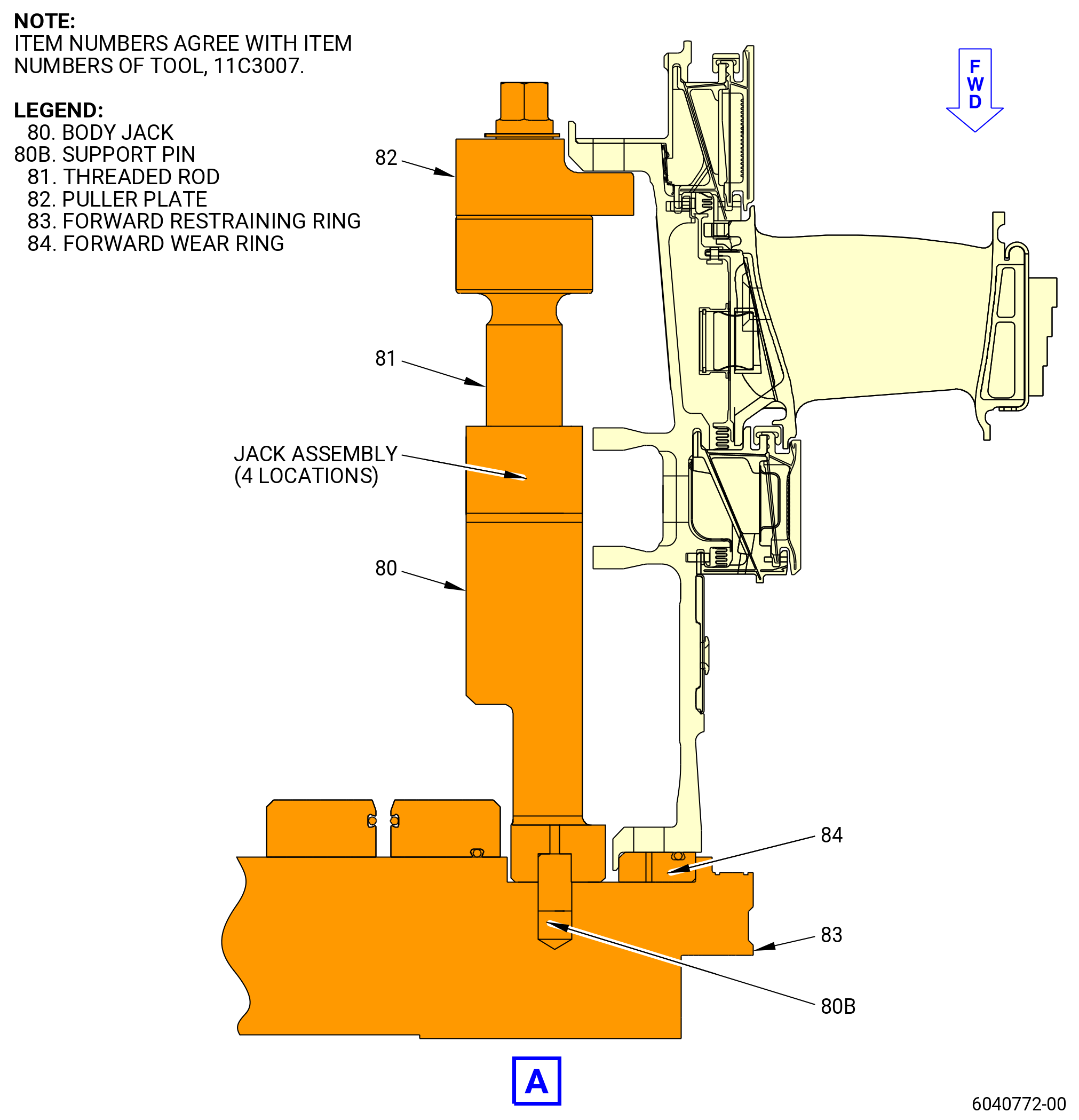
| (2) | Put the spreader bar (item 29) and cable assembly (item 28) on the forward retaining ring (item 13). |
| WARNING: |
|
| (3) | Lift the forward restraining ring (item 13) and put it on an applicable work surface in order to work on the bottom of it. |
| (4) | Loosen but do not remove the setscrews (item 70). |
| WARNING: |
|
| (5) | Clean the mounting flange of the forward restraining ring (item 13) and the stage 2 nozzle assembly case flange with C04-035 isopropyl alcohol. |
| (6) | Lift the stage 2 nozzle assembly and move it over the restraining ring (item 13). |
| (7) | Line up the top vertical centerline on the stage 2 nozzle assembly and the forward restraining ring (item 13). |
| (8) | Lower the stage 2 nozzle assembly to the forward restraining ring (item 13) and engage the straight pin (item 13B) into the off set hole near the 12:00 o'clock position of the HPT nozzle assembly. |
| (9) | Make sure that the holes in the HPT nozzle assembly flange line up with the holes in the forward restraint ring (item 13). |
| NOTE: |
|
| (10) | Line up the top vertical centerline and put the four forward ring nut plates (item 9) on the stage 2 nozzle assembly forward flange. Refer to Figure 1036. |
| (11) | Put the capscrews (item 60) and finger pins (item 46) through the stage 2 nozzle assembly flange and the forward restraining ring. |
| (12) | Torque the capscrews (item 60), in a criss-cross pattern, in 50 lb in. (5.6 N.m.) increments. Do the final torque in a circle pattern to 202-238 lb in. (22.8-26.9 N.m.). |
| (13) | Remove the four setscrews (item 70) from the forward restraining ring. |
| (14) | Measure and record the distance from the bottom of the forward restraining ring (item 13) to the stage 2 nozzle assembly forward flange as follows: |
| (a) | Make sure that the distance is within 0.001 inch (0.03 mm) of the thickness stamped on the bottom of the restraining ring (item 13). |
| (b) | If not, loosen the capscrews (item 60) and finger pins (item 46) and torque again. |
| (c) | Replace the setscrews (item 70). |
| (15) | Tighten the pusher rods (item 38) to restrain the hangars during the grinding operation. |
| (16) | Remove the spreader bar (item 29). |
| Subtask 72-52-00-220-061 |
| NOTE: |
|
| (a) | Do a runout on the OD of the forward restraining ring (item 13) to make sure that the base (item 12) is in the center of the grind machine. |
| 1 | Turn the setscrews (item 54) in the positioning blocks (item 10) as necessary to put the retaining ring (item 13) in the center of the grind machine. |
| Subtask 72-52-00-220-062 |
| WARNING: |
|
| (17) | Clean the aft flange of the stage 2 nozzle assembly, o-ring (item 6) groove, o-ring, and mating face of the aft restraining ring (item 7) with C04-035 isopropyl alcohol. |
| (18) | Attach a sling to the restraining ring (item 7). |
| WARNING: |
|
| (19) | Lift the aft restraining ring (item 7) over the aft flange of the stage 2 nozzle assembly and line up the vertical marks. |
| (20) | Align the pin (item 7B) with the offset hole in the case. |
| (21) | Lower the aft restraining ring to the aft flange of the HPT stator case. |
| (22) | Use a mallet to lightly hit all the way around the aft side of the aft restraining ring (item 7) to seat it. |
| (23) | Remove the sling. |
| Subtask 72-52-00-220-063 |
| NOTE: |
|
| (24) | Line up the top vertical centerline and put the four forward ring nut plates (item 8) on the stage 2 nozzle assembly forward flange. |
| (25) | Put the capscrews (item 60) and finger pins (item 46) through the stage 2 nozzle assembly flange and the aft restraining ring. |
| (26) | Torque the capscrews (item 60), in a criss-cross pattern, in 50 lb in. (5.6 N.m.) increments. Do the final torque in a circle pattern to 202-238 lb in. (22.8-26.9 N.m.). |
| (27) | Install and torque the capscrews (item 60). |
| (28) | Put the plugs (item 24) into the boss in the turbine case nozzle cooling ports. |
| Subtask 72-52-00-220-064 |
| (29) | Remove the plugs from the forward (item 13) and aft restraining ring (item 7). |
| (30) | Make sure that the forward (item 13) and aft restraining ring (item 7) are seated. |
| Subtask 72-52-00-220-065 |
| (31) | Measure and record DIM H125S at four equally spaced locations on the aft restraining ring (item 7). Refer to Figure 1037 and do as follows: |
| (a) | Measure dimension H125S from the fixture surface to the fixture seating surface. |
| (b) | Subtract the aft restraining ring measurement from each measurement. |
| (c) | Find the average measurement for H125S. Make a record of the average measurement. |
| (d) | Dimension H125S is 9.379 to 9.391 inches (238.23 to 238.53 mm). |
| Subtask 72-52-00-220-066 |
| (32) | Insert the eight plugs (item 24) and tighten them. Refer to Figure 1036. |
| (33) | Insert the 14 heat shield hole plugs. |
| (34) | Insert the two threaded caps into the borescope plug ports. |
| Subtask 72-52-00-220-067 |
| (e) | Make sure that the stage 2 nozzle assembly is against the forward restraining ring (item 13). Refer to Figure 1036 and do as follows: |
| 1 | Remove and discard the four setscrews (item 70) on the bottom of the forward restraining ring (item 13). |
| 2 | Measure through the hole to the stage 2 nozzle assembly flange. |
| 3 | Compare the measurements to the dimension stamped on the forward clamping plate (item 4). Make sure that the measurements are within 0.001 inch (0.03 mm) of the dimension stamped on the forward clamping plate. |
| Subtask 72-52-00-440-111 |
| 4 | If the stage 2 nozzle assembly is not against the forward restraining ring (item 13), loosen the capscrews (item 60). |
| 5 | Torque the capscrews (item 60), in a criss-cross pattern, in 50 lb in. (5.6 N.m.) increments. Do the final torque in a circle pattern to 202-238 lb in. (22.8-26.9 N.m.). |
| CAUTION: |
|
| 6 | Install four new setscrews (item 70) in the forward restraining ring (item 13). |
| (f) | Put the clamp ring (item 26) on the forward restraining ring (item 13) and attach firmly with the capscrews (item 59). |
| (g) | Put the clamp ring (item 25) on the forward restraining ring (item 13) and attach it firmly with the capscrews (item 59). |
| (h) | Make sure that the O-ring (item 23) is correctly installed in the groove. |
| (i) | Install the manifold (item 15) as follows: |
| 1 | Check the mating surface and if necessary, remove all high metal. Refer to TASK 70-42-00-350-002 (BLENDING AND REMOVAL OF HIGH METAL PROCEDURES). |
| WARNING: |
|
| 2 | Clean the manifold seating surfaces with C04-035 isopropyl alcohol. |
| WARNING: |
|
| 3 | Attach a lifting device and lift the manifold (item 15). Line up the 12:00 o'clock marks and lower the manifold onto the base (item 12). |
| 4 | Remove the lifting device. |
| 5 | Attach the manifold with the manifold bolts and torque them, in a criss-cross pattern, in 50 lb in. (5.6 N.m.) increments. Do a final torque to 202-238 lb in. (22.8-26.9 N.m.) in a circular pattern. |
| (j) | Attach a lifting device to the shell support (item 5) and lower it onto the forward restraining ring (item 13). |
| (k) | Attach the shell support (item 5) to the forward restraining ring (item 13) with setscrews (item 70). |
| (l) | Turn the grind assembly aft end up as follows: |
| 1 | Attach an overhead hoist to the spreader bar (item 29). |
| 2 | Install the ball lock pins (item 30). |
| 3 | Lift the 11C3007 shroud grind fixture. |
| WARNING: |
|
| WARNING: |
|
| 4 | Turn the grind assembly forward side down as follows: |
| a | Put a lift sling 90 degrees from the pivot point of the shroud grind fixture. Restrain the shroud grind fixture with the lift sling. |
| b | Remove the ball lock pins (item 30). |
| c | Slowly turn the shroud grind fixture with the lift sling. |
| d | Install the ball lock pins (item 30) when the stage 2 nozzle grind assembly is turned. |
| e | Remove the lift sling located 90 degrees from the pivot point of the shroud grind fixture. |
| (m) | Install the shell support (item 5) as follows: |
| 1 | Put the hoist rings in the top of the shell support (item 5). Attach the three piece sling to the hoist rings. |
| 2 | Lift the shell support (item 5) with the three piece sling and a hoist. |
| Subtask 72-52-00-110-012 |
| WARNING: |
|
| CAUTION: |
|
| 3 | Clean the shell support (item 5) with C04-035 isopropyl alcohol. |
| 4 | Make sure that the bottom and the top inner ring of the shell support (item 5) are clean. |
| Subtask 72-52-00-440-112 |
| 5 | Align the top vertical centerline of the shell support (item 5) with the top vertical centerline of the stage 2 nozzle assembly. Lower the shell support (item 5) to the forward restraining ring (item 13). |
| 6 | Remove the hoist, sling, and hoist rings from the shell support (item 5). |
| 7 | Install the capscrews (item 59) to attach the shell support (item 5) to the forward restraining ring (item 13). |
| 8 | Torque the capscrews (item 59) to 160-210 lb in. (18.1-23.7 N.m). |
| 9 | Install the capscrews (item 64) to attach the shell support (item 5) to the aft clamping plate (item 5). |
| 10 | Torque the capscrews (item 64) to 160-210 lb in. (18.1-23.7 N.m). |
| 11 | Make sure that the female pipe swivels (item 45) on the shell support (item 5) are tight. |
| Subtask 72-52-00-440-113 |
| (35) | Prepare the stage 2 nozzle assembly to grind the stage 1 shrouds. Refer to Figure 1036 and do as follows: |
| (a) | Turn the stage 2 nozzle assembly and shroud grind fixture (stage 2 nozzle grind assembly) as follows: |
| 1 | Attach a hoist to the spreader bar (item 29). |
| 2 | Make sure that the ball lock pins (item 30) are installed. |
| WARNING: |
|
| WARNING: |
|
| 3 | Lift the stage 2 nozzle grind assembly as follows: |
| a | Put a lift sling 90 degrees from the pivot point of the shroud grind fixture. Restrain the shroud grind fixture with the lift sling. |
| b | Remove the ball lock pins (item 30). |
| WARNING: |
|
| c | Slowly turn the shroud grind fixture with the lift sling. |
| d | Install the ball lock pins (item 30) when the stage 2 nozzle grind assembly is turned. |
| e | Remove the lift sling from 90 degrees of the pivot point of the shroud grind fixture. |
| (b) | Put the stage 2 nozzle grind assembly on the base (item 12) as follows: |
| WARNING: |
|
| 1 | Clean the mating surface of the base (item 12) with C04-035 isopropyl alcohol. |
| 2 | Clean the mating surface of the forward restraining ring (item 13) with C04-035 isopropyl alcohol. |
| 3 | Put the forward restraining ring (item 13) over the base (item 12). Align the large locator hole in the forward restraining ring (item 13) with the restricting pin (item 11) in the base (item 12). |
| 4 | Lower the stage 2 nozzle grind assembly until it is 0.125 inch (3.18 mm) above the base (item 12). |
| 5 | Install the locator pins (item 2) 90 degrees from the restricting pin (item 11). If a pin will not go in the first hole that is tried, put it in the other hole. Use a plastic mallet to help with the installation of the pins. |
| 6 | Lower the stage 2 nozzle grind assembly on the base (item 12). |
| 7 | Remove the capscrews (item 52) that attach the spreader bar (item 29) and brackets (item 27) to the forward restraining ring (item 13). Remove the spreader bar (item 29) from the stage 2 nozzle grind assembly. |
| Subtask 72-52-00-220-068 |
| CAUTION: |
|
| 8 | Do a runout of surface T on the clamp ring (item 25). Make sure that the runout is less than 0.001 inch (0.03 mm). Put a mark at the highest point of the runout. Refer to Figure 1024. |
| 9 | If the runout is not in limits, adjust the forward restraining ring (item 13) with the capscrews (item 54). |
| Subtask 72-52-00-440-114 |
| 10 | Attach the forward restraining ring (item 13) to the base (item 12) with capscrews (item 52). Do not tighten the screws. |
| Subtask 72-52-00-220-069 |
| 11 | Do an inspection of the flatness of the forward restraining ring (item 13) as follows: |
| a | Begin at the highest point of the runout and tighten the capscrew (item 52) at that location. Continue to tighten the remaining bolts. |
| b | Make sure that the total flatness is not more than 0.0015 inch (0.038 mm). |
| Subtask 72-52-00-440-115 |
| 12 | Get a sample of the coolant used for grinding. |
| 13 | Connect the hoses (item 14) to the support shell (item 5) with the quick disconnect nipple (item 43). |
| Subtask 72-52-00-320-017 |
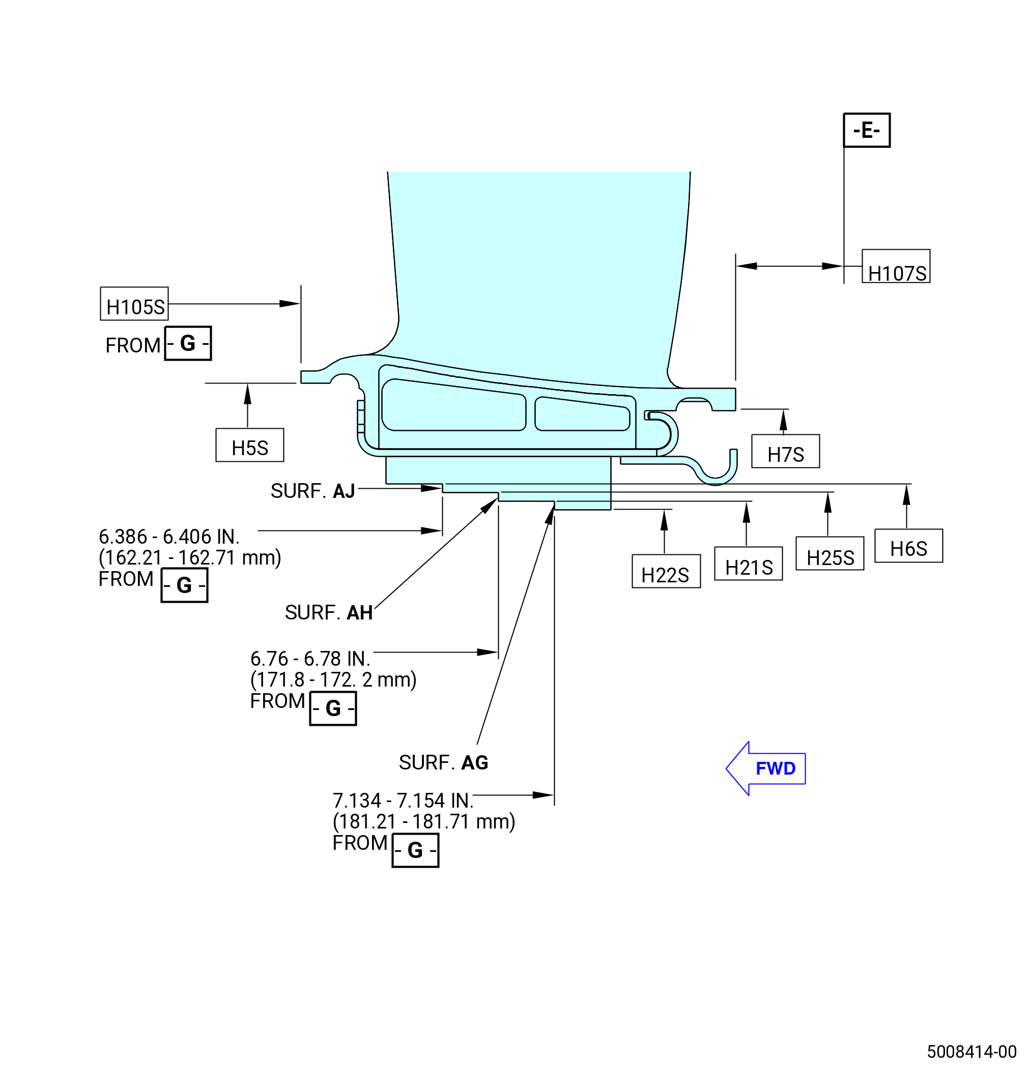
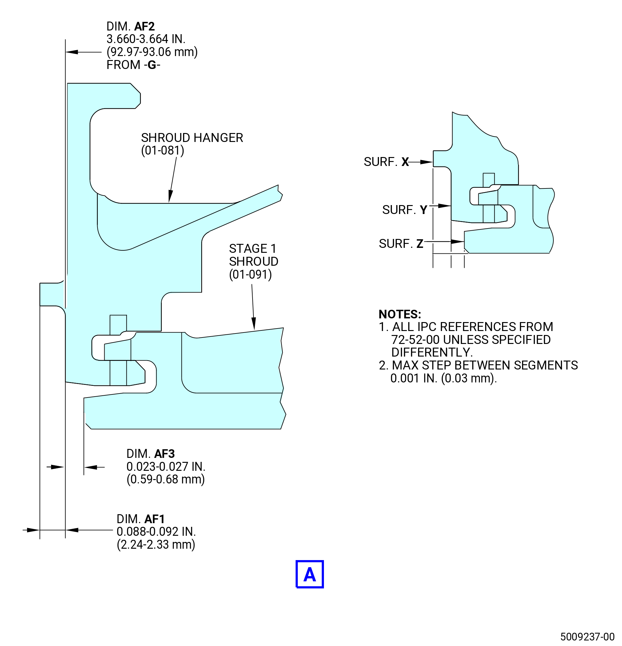
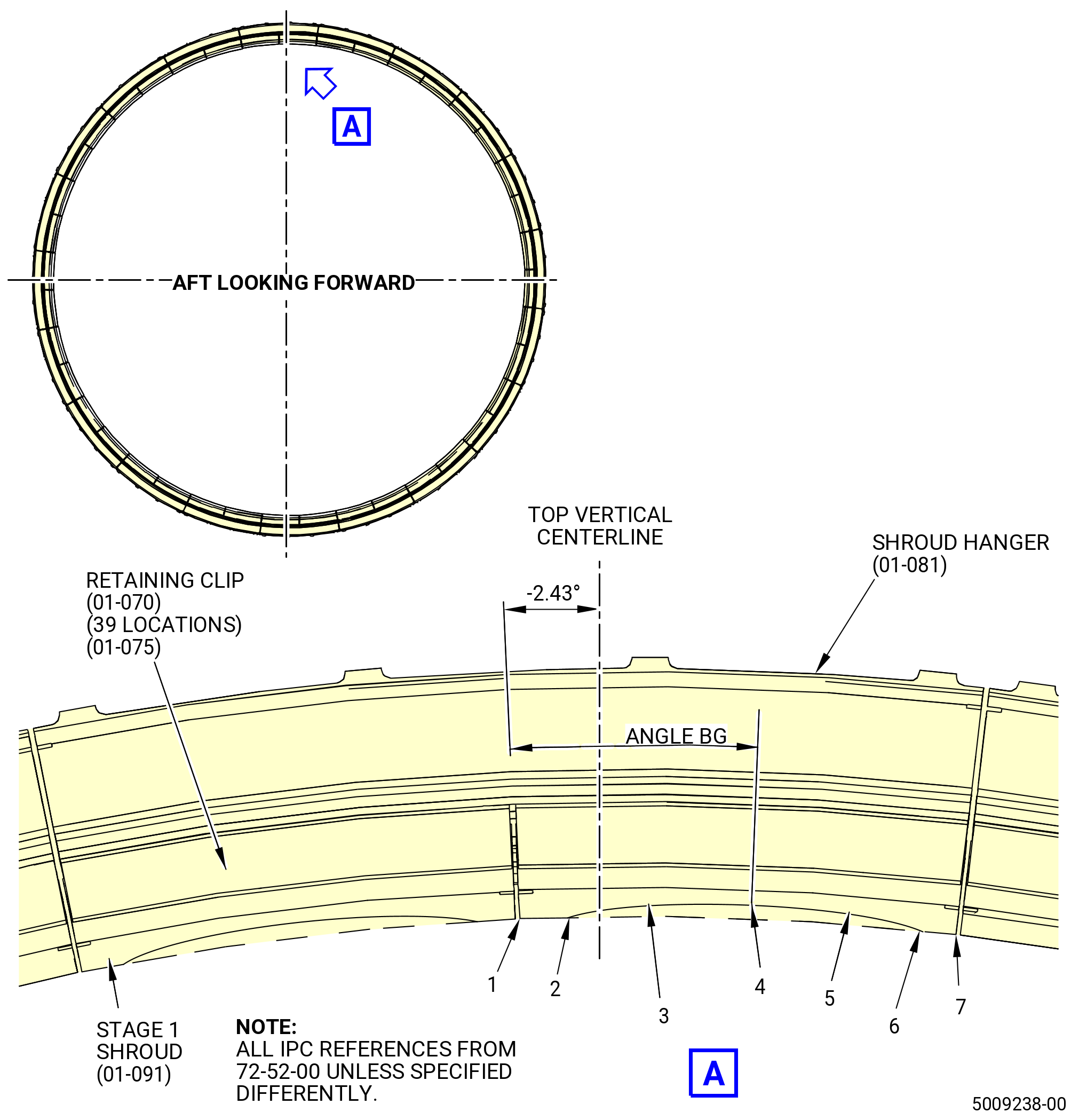
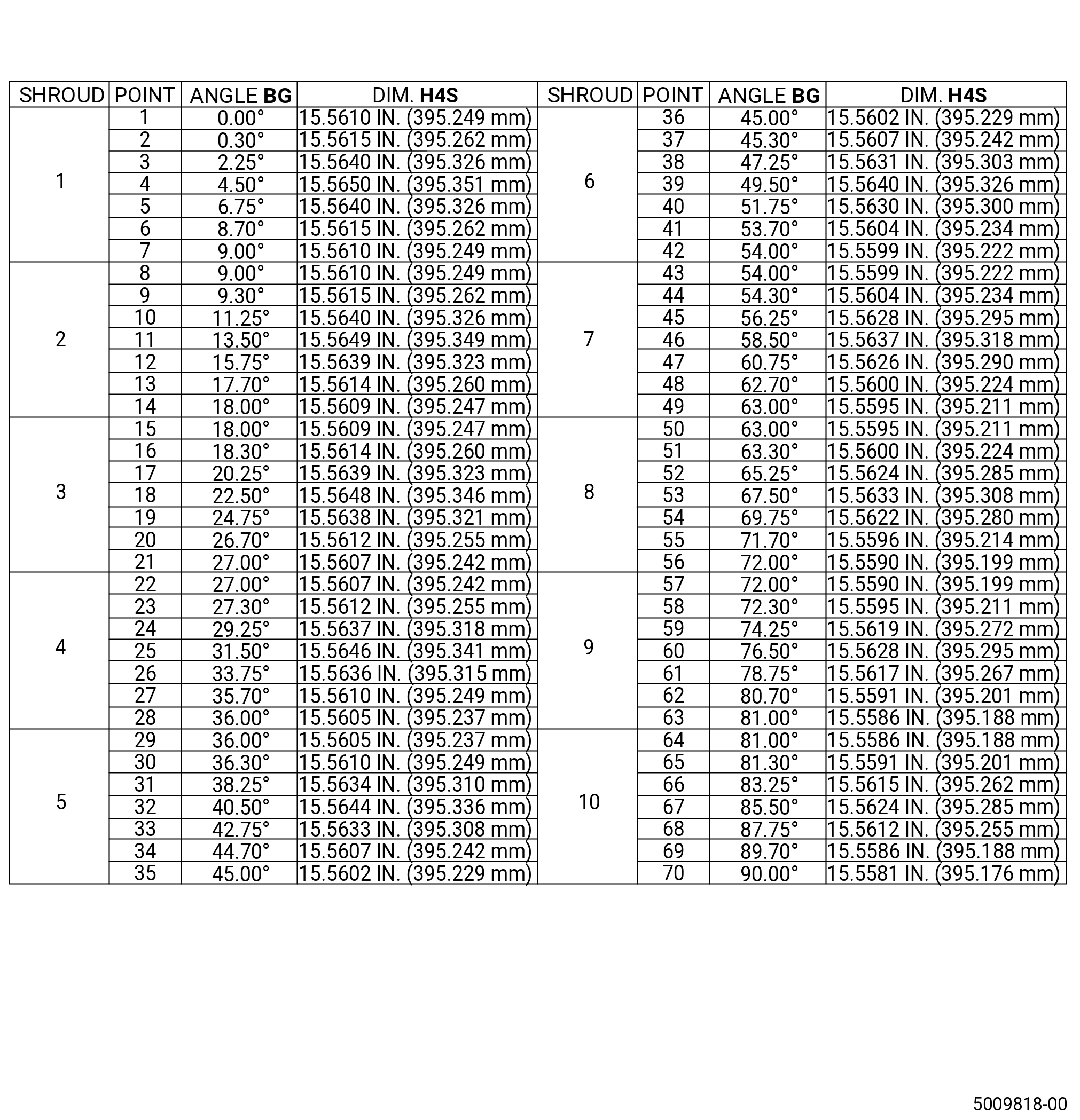
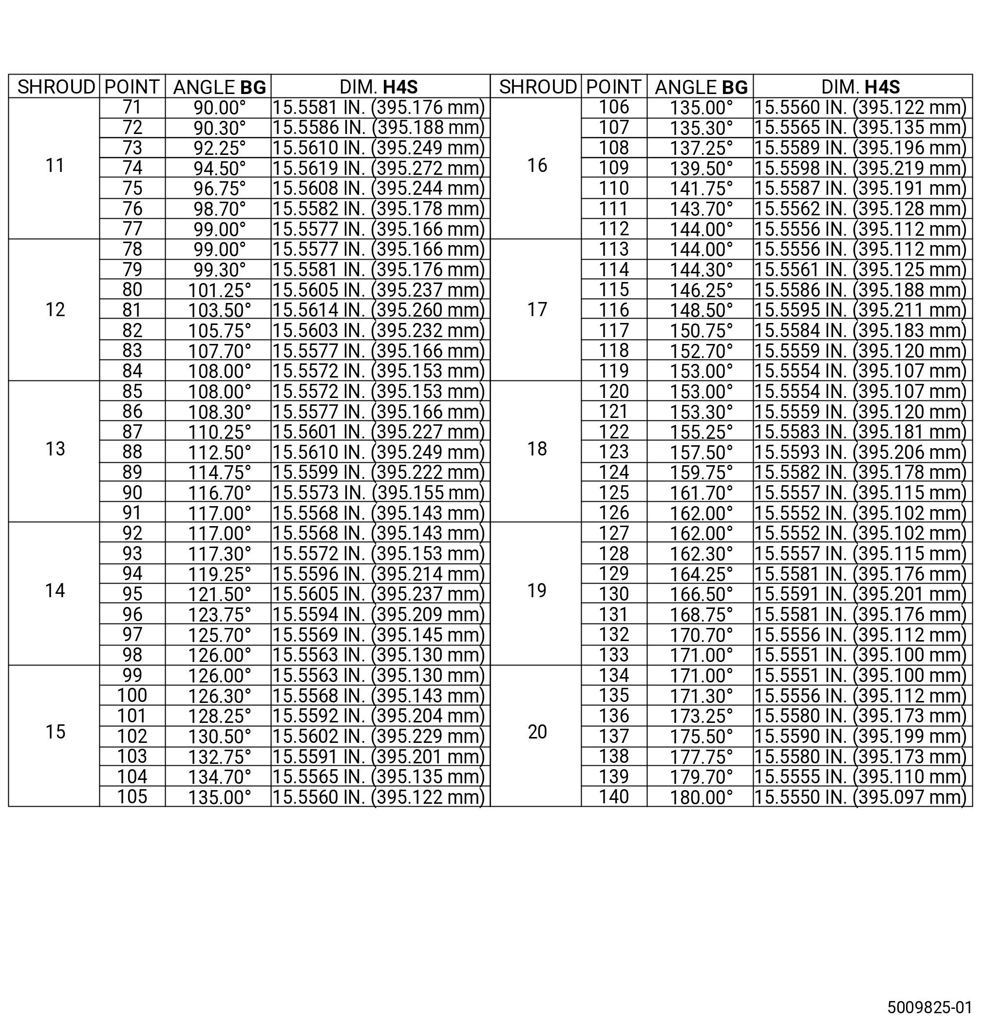
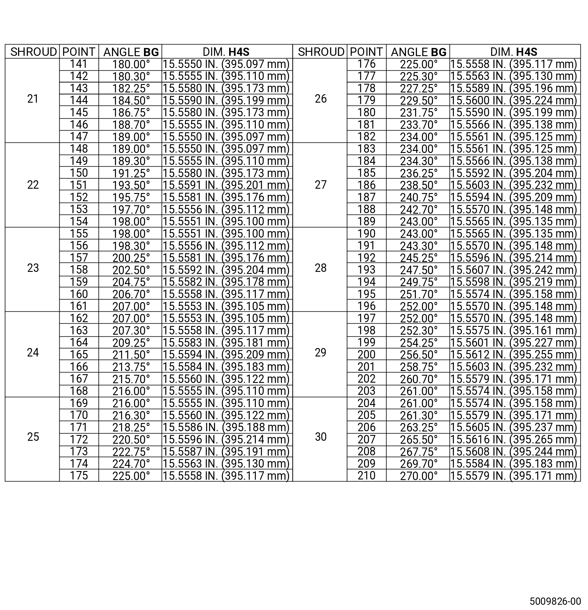
| (36) | Grind the stage 1 shrouds and surfaces AF1, AF2 and AF3. Refer to Figure 1037, Figure 1038, and do as follows: |
| Subtask 72-52-00-110-013 |
| WARNING: |
|
| (a) | Clean the stage 1 shrouds (dimension H4S) and surfaces AF1 and AF3 with C04-035 isopropyl alcohol. |
| Subtask 72-52-00-320-018 |
| WARNING: |
|
| (b) | Refer to the grind machine manufacture's instructions and Figure 1038 to grind the stage 1 shrouds (dimension H4S). |
| (c) | Refer to the grind machine manufacturer's instructions and Figure 1037 to grind surfaces AF1, AF2, and AF3. |
| (d) | Record the grind dimension at points 1 and 7 on 20 equally spaced stage 1 shrouds. Refer to Figure 1038. |
| (e) | Record the minimum and maximum dimensions from paragraph 3.N.(36)(d) for H4S on the data sheet. |
| (f) | Record the average from paragraph 3.N.(36)(d) for H4S on the data sheet. |
| (g) | Make sure to get a full clean up on surfaces AF1, AF2, and AF3. Make sure that the maximum step between segments on surface AF1 is less than 0.001 inch (0.03 mm). |
| NOTE: |
|
| Subtask 72-52-00-440-116 |
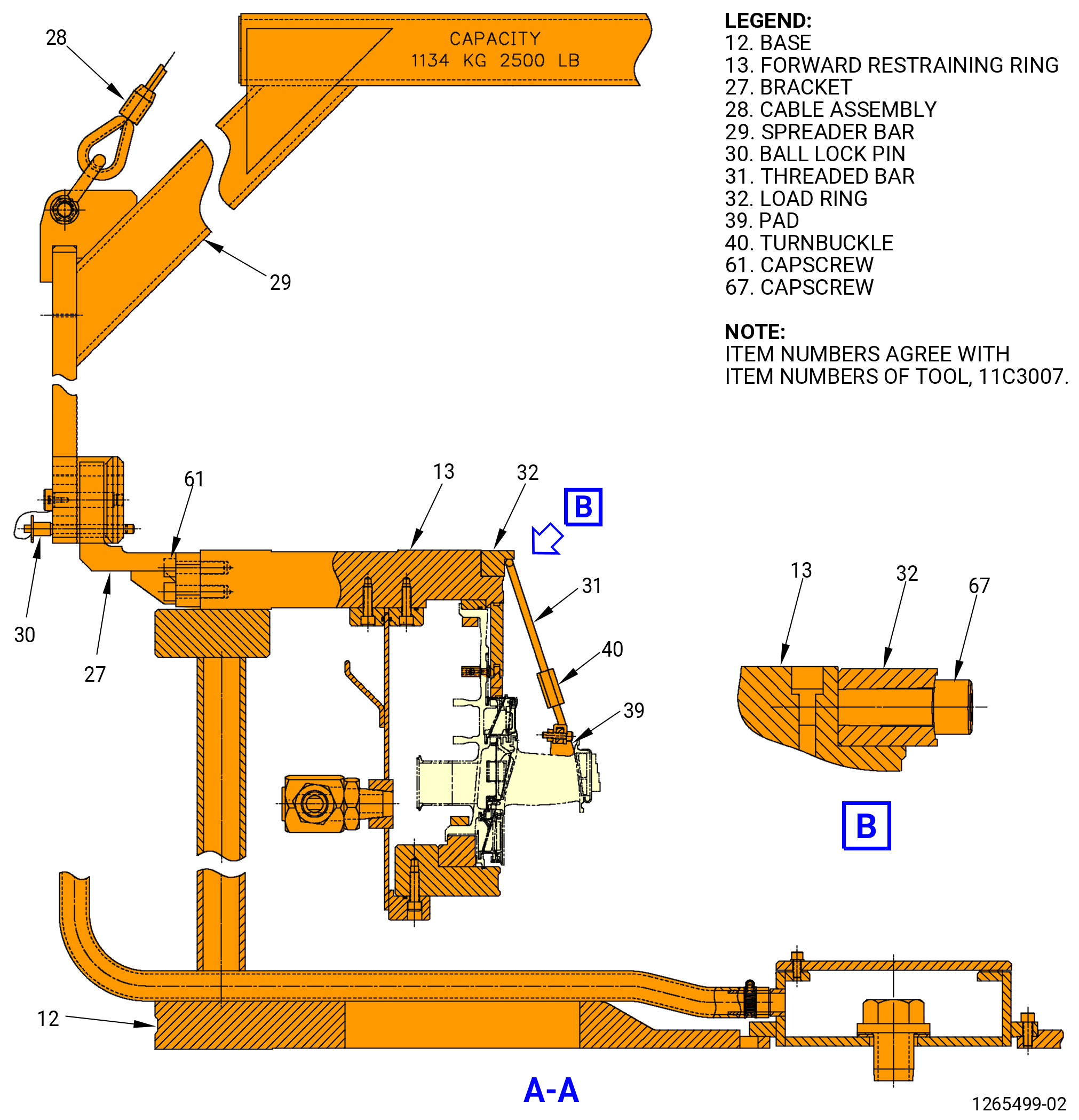
| (37) | Install the stage 2 nozzle preload fixture. Refer to Figure 1035 and do as follows: |
| (a) | Make sure that the turnbuckle assemblies are in the correct position. |
| NOTE: |
|
| WARNING: |
|
| (b) | Attach a three-legged sling and an overhead hoist to the lift rings on the load ring (item 32) and lift the preload fixture over the stage 2 nozzle grind assembly. |
| (c) | Align the slot in the load ring (item 32) with the pin in the forward restraining ring (item 13). Lower the preload fixture on the inner flange of the forward restraining ring (item 13). |
| (d) | Attach the load ring (item 32) to the forward restraining ring (item 13) with the capscrews (item 67). |
| (e) | Find the run-on torque of the turnbuckles (item 40). Make a record of the run-on torque. |
| (f) | Put the turnbuckles (item 40) against the nozzle segments. |
| CAUTION: |
|
| NOTE: |
|
| (g) | Torque the turnbuckles (item 40) to 35 lb in. (4.0 N.m) above the run-on torque. A number of passes can be necessary to torque the turnbuckles to 35 lb in. (4.0 N.m). |
| (h) | Make sure to continue the torque procedure until there is no movement of the turnbuckle nut when the torque is applied. |
| (i) | Remove the three lift rings from the load ring (item 32). |
| Subtask 72-52-00-320-019 |
| (38) | Grind the ID forward seal lip and honeycomb seal of the nozzle segments. Refer to Figure 1037 and do as follows: |
| WARNING: |
|
| (a) | Grind the honeycomb seal (dimension H6S). Refer to the grind machine manufacturer's instructions. |
| Subtask 72-52-00-220-070 |
| (b) | Make a record of the final dimension for H6S on the data sheet. |
| Subtask 72-52-00-320-020 |
| WARNING: |
|
| (c) | Grind the honeycomb seal (dimension H25S). Refer to the grind machine manufacturer's instructions. |
| Subtask 72-52-00-220-071 |
| (d) | Make a record of the final dimension for H25S on the data sheet. |
| Subtask 72-52-00-320-021 |
| WARNING: |
|
| (e) | Grind the honeycomb seal (dimension H21S). Refer to the grind machine manufacturer's instructions. |
| Subtask 72-52-00-220-091 |
| (f) | Make a record of the final dimension for H21S on the data sheet. |
| Subtask 72-52-00-320-028 |
| WARNING: |
|
| (g) | Grind the honeycomb seal (dimension H22S). Refer to the grind machine manufacturer's instructions. |
| Subtask 72-52-00-220-092 |
| (h) | Make a record of the final dimension for H22S on the data sheet. |
| Subtask 72-52-00-320-029 |
| WARNING: |
|
| (i) | Grind the ID of the forward seal lip (dimension H5S). Refer to the grind machine manufacturer's instructions. |
| Subtask 72-52-00-220-072 |
| (j) | Record the minimum and maximum dimension for H5S on the data sheet. |
| Subtask 72-52-00-320-022 |
| WARNING: |
|
| (k) | Grind the ID forward seal lip (dimension H105S). Refer to the grind machine manufacturer's instructions. |
| Subtask 72-52-00-220-073 |
| (l) | Make a record of the final dimension for H105S. |
| Subtask 72-52-00-320-039 |
| (m) | Grind the ID aft seal lip H107S. Refer to Figure 1037 and machine manufacturer's instructions for machining. |
| Subtask 72-52-00-220-103 |
| (n) | Make a record of the final dimension H107S. |
| Subtask 72-52-00-320-040 |
| (o) | Machine the ID aft seal lip H7S. Refer to Figure 1037 and machine manufacturer's instructions for machining. |
| Subtask 72-52-00-220-104 |
| (p) | Make a record of the final dimension H7S. |
| Subtask 72-52-00-320-030 |
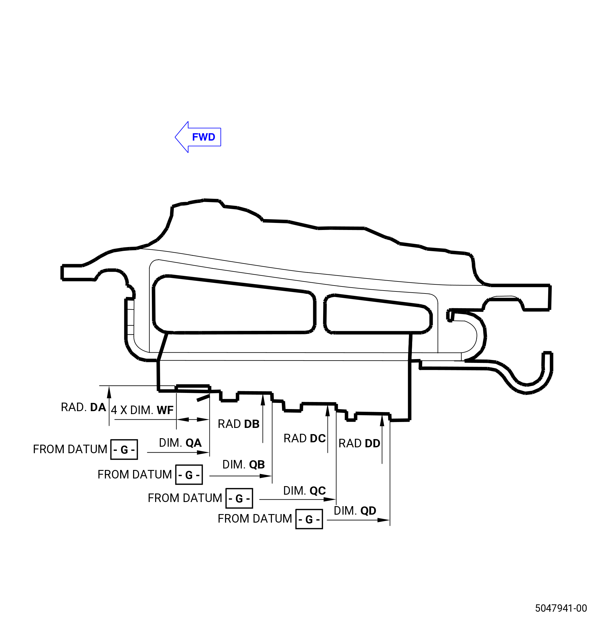
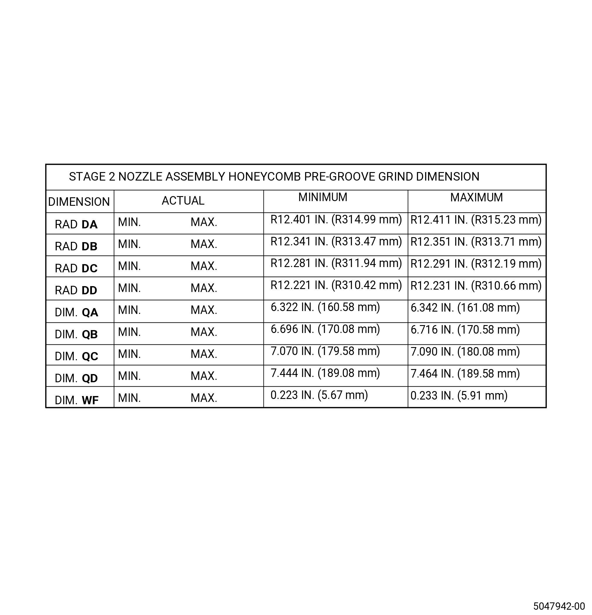
| (39) | Optional Procedure. Grind the pre-grooves in the honeycomb seal of the nozzle segments. Refer to Figure 1039 and do as follows: |
| NOTE: |
|
| WARNING: |
|
| (a) | Grind the honeycomb seal (radius DA). Refer to the grind machine manufacturer's instructions. |
| Subtask 72-52-00-220-093 |
| (b) | Make a record of the final dimension for radius DA and dimension QA on the data sheet. |
| Subtask 72-52-00-320-031 |
| WARNING: |
|
| (c) | Grind the honeycomb seal (radius DB). Refer to the grind machine manufacturer's instructions. |
| Subtask 72-52-00-220-094 |
| (d) | Make a record of the final dimension for radius DB and dimension QB on the data sheet. |
| Subtask 72-52-00-320-032 |
| WARNING: |
|
| (e) | Grind the honeycomb seal (radius DC). Refer to the grind machine manufacturer's instructions. |
| Subtask 72-52-00-220-095 |
| (f) | Make a record of the final dimension for radius DC and dimension QC on the data sheet. |
| Subtask 72-52-00-320-033 |
| WARNING: |
|
| (g) | Grind the honeycomb seal (radius DD). Refer to the grind machine manufacturer's instructions. |
| Subtask 72-52-00-220-096 |
| (h) | Make a record of the final dimension for radius DD and dimension QD on the data sheet. |
| Subtask 72-52-00-440-117 |
| NOTE: |
|
| (40) | Prepare the stage 2 nozzle assembly to grind the stage 2 shrouds. Refer to Figure 1036 and do as follows: |
| (a) | Remove the capscrews (item 52) that attach the forward restraining ring (item 13) to the base (item 12). |
| (b) | Remove the setscrews (item 54) from against the forward restraining ring (item 13). |
| (c) | Remove the hoses (item 14) from the quick disconnect nipples (item 43). |
| (d) | Attach the spreader bar (item 29) and brackets (item 27) to the forward restraining ring (item 13) with the capscrews (item 61). Refer to Figure 1035. |
| WARNING: |
|
| (e) | Lift the forward restraining ring (item 13) slowly off of the base (item 12). Lift the forward restraining ring 24.0 inches (610 mm) above the base (item 12). Refer to Figure 1036. |
| (f) | Put the lift slings at two locations 90 degrees from the pivot point of the spreader bar (item 29). |
| WARNING: |
|
| (g) | Remove the ball lock pins (item 30) and tilt the stage 2 nozzle grind assembly to remove the coolant. Use the lift slings at 90 degrees from the pivot point to support the stage 2 nozzle grind assembly when turned. |
| (h) | Put the stage 2 nozzle assembly back to level and install the ball lock pins (item 30) when the coolant is removed. Refer to Figure 1035. |
| (i) | Remove the stage 2 nozzle grind assembly from the grind machine. |
| (j) | Turn the stage 2 nozzle grind assembly 180 degrees as follows: |
| 1 | Lift the stage 2 nozzle grind assembly to a height that will let the assembly turn 180 degrees. |
| 2 | If not already installed, put lift slings 90 degrees from the pivot point of the spreader bar (item 29). |
| WARNING: |
|
| 3 | Support the stage 2 nozzle grind assembly with the lift slings 90 degrees from the pivot point. Remove the ball lock pins (item 30). |
| 4 | Turn the stage 2 nozzle grind assembly 180 degrees. |
| 5 | Install the ball lock pins (item 30). |
| (k) | Put the stage 2 nozzle grind assembly on the base (item 12). Refer to Figure 1036 and do as follows: |
| 1 | Make sure that the mating surface of the base (item 12) is clean. |
| 2 | Make sure that the mating surface of the forward restraining ring (item 13) is clean. |
| 3 | Put the forward restraining ring (item 13) over the base (item 12). Align the large locator hole in the forward restraining ring (item 13) with the locator pin in the base (item 12). |
| 4 | Lower the stage 2 nozzle grind assembly until it is one-eighth above the base (item 12). |
| 5 | Install the locator pins 90 degrees from the large locator pin. If a pin will not go in the first hole that is tried, put it in the other hole. Use a plastic mallet to help with the installation of the pins. |
| 6 | Lower the stage 2 nozzle grind assembly on the base (item 12). |
| 7 | Remove the capscrews (item 61) that attach the spreader bar (item 29) and brackets (item 29) to the forward clamping plate. Remove the spreader bar (item 22) from the stage 2 nozzle grind assembly. |
| Subtask 72-52-00-220-074 |
| CAUTION: |
|
| 8 | Do a runout on the ID of the forward restraining ring (item 13) to make sure that the forward restraining ring (item 13) is in the center of the grind machine. |
| a | Make sure that the runout is less than 0.001 inch (0.03 mm). |
| b | Put a mark at the highest point of the runout. |
| 9 | If the runout is not in limits, adjust the forward restraining ring (item 13) with the setscrew (item 54). |
| Subtask 72-52-00-440-118 |
| 10 | Attach the forward restraining ring (item 13) to the base (item 12) with screws (item 52). Do not tighten the screws. |
| Subtask 72-52-00-220-075 |
| 11 | Do an inspection of the flatness of the forward restraining ring (item 13) as follows: |
| a | Begin at the highest point of the runout and tighten the screw (item 52) at that location. Continue to tighten the remaining screws (item 59). |
| b | Make sure that total flatness is not more than 0.0015 inch (0.038 mm). |
| Subtask 72-52-00-440-119 |
| 12 | Connect the hoses (item 14) to the quick disconnect nipple (item 43). |
| Subtask 72-52-00-220-076 |
| (41) | Measure the surfaces (H5S, H7S, H105S, and H107S) of the nozzle segments. Refer to Figure 1037 and do as follows: |
| (a) | Clean the surfaces (H5S, H7S, H105S, and H107S) of the nozzle segments. |
| (b) | Measure H5S of the nozzle segment. Refer to the grind machine manufacturer's instructions for measurement. |
| (c) | Record the minimum and maximum dimension for H5S on the data sheet. |
| (d) | Measure H7S of the nozzle segment. Refer to the grind machine manufacturer's instructions for measurement. |
| (e) | Record the minimum and maximum dimension for H7S on the data sheet. |
| (f) | Measure H105S of the nozzle segment. Refer to the grind machine manufacturer's instructions for measurement. |
| (g) | Record the data for H105S on the data sheet. |
| (h) | Measure H107S of the nozzle segment. Refer to the grind machine manufacturer's instructions for measurement. |
| (i) | Record the data for H107S on the data sheet. |
| Subtask 72-52-00-320-023 |
| (42) | Grind the stage 2 shrouds (dimension H8S) as follows: |
| Subtask 72-52-00-110-014 |
| WARNING: |
|
| (a) | Clean the stage 2 shrouds with C04-035 isopropyl alcohol. |
| Subtask 72-52-00-320-024 |
| WARNING: |
|
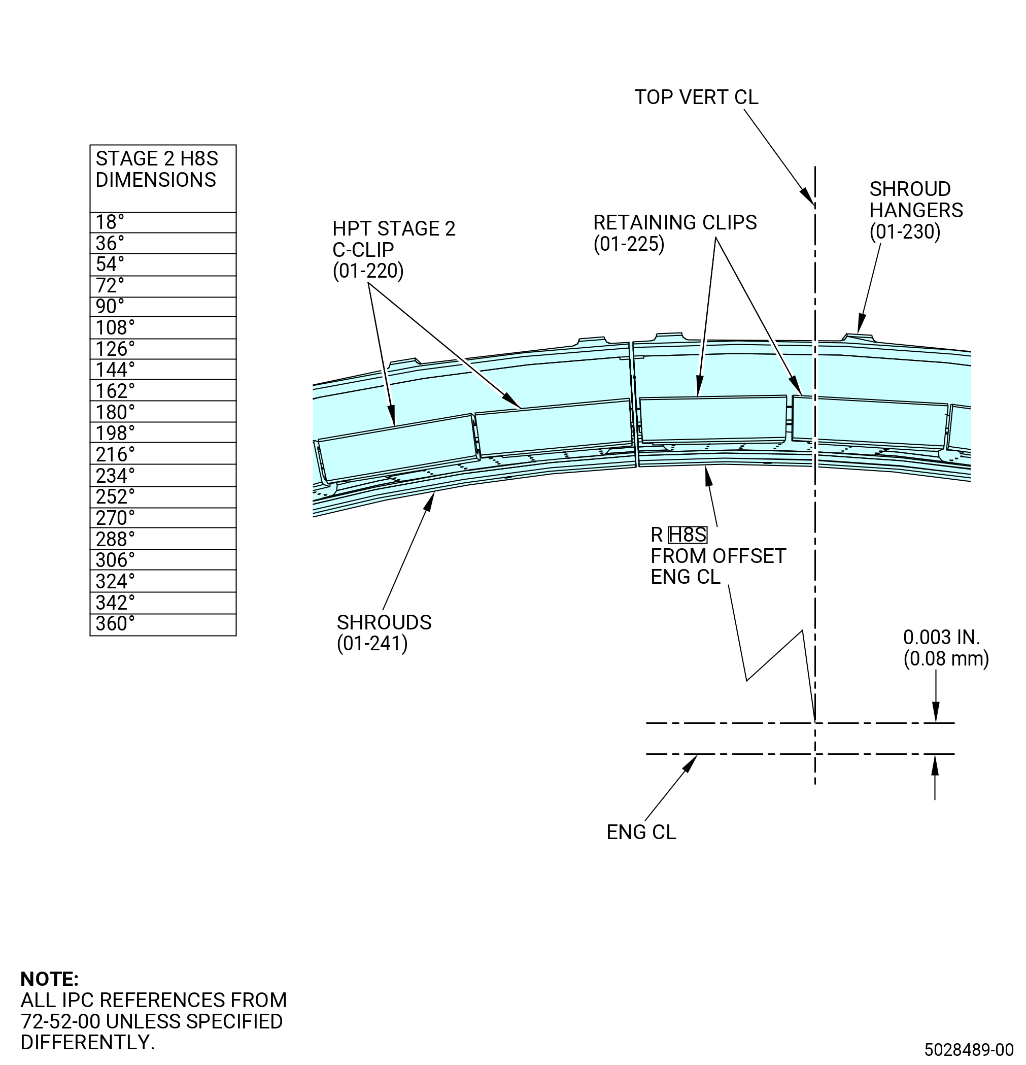
| (b) | Grind the shrouds (01-241) (SIN 17800) (dimension H8S) to a target radius of 16.1625-16.1655 inches (410.528-410.603 mm). Note that center of grinding is 0.003 inch (0.08 mm) offset from engine center line along top vertical center line. Refer to Figure 1040. Refer to the grind machine manufacturer's instructions. |
| (c) | Make a record of the grind dimension at 20 equally spaced locations for the shrouds (01-241) (SIN 17800). Refer to Figure 1040. |
| Subtask 72-52-00-220-077 |
| (d) | Make a record of the minimum and maximum dimensions for H8S on the data sheet. Refer to Figure 1037. |
| (e) | Find the average for H8S. Make a record of the dimension on the data sheet. |
| Subtask 72-52-00-440-120 |
| (43) | Prepare to do an inspection of the stage 2 nozzle assembly after the grind operations are complete. Refer to Figure 1036 and do as follows: |
| (a) | Remove the hoses (item 14) from the quick disconnect nipple (item 43) on the shell support (item 5). |
| (b) | Get a sample of the coolant. Put a mark on the container as POST GRIND SAMPLE. |
| (c) | Remove the capscrews (item 26) that attach the shell support (item 5) to the forward restraining ring (item 13). |
| WARNING: |
|
| (d) | Attach a hoist to the shell support (item 5). Lift the shell support (item 5) from the forward restraining ring (item 13). |
| (e) | Remove the plugs (item 24) from the stage 2 nozzle case. |
| Subtask 72-52-00-220-078 |
| (44) | Do an inspection of the impingement ring holes as follows: |
| • |
|
| • |
|
| • |
|
| Subtask 72-52-00-220-079 |
| (45) | Do an inspection of the baffles in the impingement ring as follows: |
| • |
|
| • |
|
| • |
|
| Subtask 72-52-00-220-080 |
| (46) | Do an inspection of the nozzle insert nose holes as follows: |
| • |
|
| • |
|
| • |
|
| Subtask 72-52-00-220-081 |
| (47) | Do an inspection of the nozzle insert baffles as follows: |
| • |
|
| • |
|
| • |
|
| Subtask 72-52-00-440-121 |
| (48) | Install the plugs (item 24) in the stage 2 nozzle case. |
| (49) | Install the support shell (item 5) on the forward restraining ring (item 13) with the capscrews (item 59). |
| (50) | Torque the capscrews (item 59) to 100 lb in. (11.3 N.m). |
| Subtask 72-52-00-440-122 |
| (51) | Deleted. |
| Subtask 72-52-00-440-123 |
| (52) | Remove the stage 2 nozzle grind assembly from the grind machine. Refer to Figure 1036 and do as follows: |
| (a) | Remove the screws (item 52) that attach the forward restraining ring (item 13) to the base (item 12). |
| (b) | Remove the hoses (item 14) from the quick disconnect coupling (item 44) on the support shell (item 5). |
| (c) | Attach the spreader bar (item 29) and brackets (item 27) to the forward restraining ring with the capscrews (item 61). Refer to Figure 1035. |
| (d) | Make sure that the ball lock pins (item 30) are installed in the spreader bar and brackets. |
| WARNING: |
|
| (e) | Lift the forward restraining ring (item 13) slowly off of the base (item 12). Lift the forward restraining ring 24.0 inches (610 mm) above the base (item 12). Refer to Figure 1036. |
| (f) | Put lift slings at two locations 90 degrees from the pivot point of the spreader bar (item 29). Refer to Figure 1035. |
| WARNING: |
|
| (g) | Remove the ball lock pins (item 30) and tilt the stage 2 nozzle grind assembly to remove the coolant. Use the lift slings at 90 degrees from the pivot point to support the rotation of the stage 2 nozzle grind assembly. Refer to Figure 1036. |
| (h) | Put the stage 2 nozzle assembly back to level and install the ball lock pins (item 30) when the coolant is removed. |
| (i) | Remove the stage 2 nozzle grind assembly from the grind machine. |
| (53) | Put the stage 2 nozzle grind assembly on a clean surface. |
| (54) | Remove the ball lock pins (item 30) that attach the spreader bar (item 29) to the brackets (item 27). Remove the spreader bar (item 29). |
| (55) | Remove the capscrews (item 61) that attach the brackets (item 27) to the forward restraining ring (item 13). Remove the brackets (item 27). |
| (56) | Loosen the turnbuckles (item 40) of the stage 2 nozzle preload fixture. |
| (57) | Remove the capscrews (item 59) that attach the shell support (item 5) to the forward restraining ring (item 13). Refer to Figure 1036. |
| (58) | Attach a hoist to the shell support (item 5). Lift the shell support (item 5) from the forward restraining ring (item 13). |
| (59) | Remove the plugs (item 24) from the stage 2 nozzle case. |
| Subtask 72-52-00-220-082 |
| (60) | Do an inspection of the stage 2 nozzle assembly after the grind operations are complete as follows: |
| (a) | Do an inspection of the impingement ring holes as follows: |
| • |
|
| • |
|
| • |
|
| Subtask 72-52-00-220-083 |
| (b) | Do an inspection of the baffles in the impingement ring as follows: |
| • |
|
| • |
|
| • |
|
| Subtask 72-52-00-220-084 |
| (c) | Do an inspection of the nozzle insert nose holes as follows: |
| • |
|
| • |
|
| • |
|
| Subtask 72-52-00-220-085 |
| (d) | Do an inspection of the nozzle insert baffles as follows: |
| • |
|
| • |
|
| • |
|
| Subtask 72-52-00-440-124 |
| (61) | Remove the aft restraining ring (item 7) from the stage 2 nozzle assembly. Refer to Figure 1036 and do as follows: |
| (a) | Remove the capscrews (item 60) that attach the aft nut plate ring (item 8) to the stage 2 nozzle assembly. |
| (b) | Remove the capscrews (item 60) and aft nut plate ring (item 8) from the stage 2 nozzle assembly. |
| (c) | Attach a hoist to the aft restraining ring (item 7). |
| WARNING: |
|
| (d) | Lift the aft restraining ring (item 7) from the stage 2 nozzle assembly. If necessary, tap the aft clamp ring with a plastic mallet to help with the removal. |
| Subtask 72-52-00-440-125 |
| (62) | Remove the stage 2 nozzle assembly from the restraining ring (item 13) as follows: |
| (a) | If the stage 2 nozzle assembly is bound to the fixture use four jack assemblies (80, 81, and 82). Refer to Figure 1036 (Sheet 3) and do as follows: |
| 1 | Install the four jack assemblies on the fwd restraining ring (item 83) surface by engaging the support pin (item 80B) in the pin holes located on the fwd restraining ring (item 83). |
| 2 | Expand the threaded rod (item 81) by turning it manually on the knurled area until contacting the HPT case aft flange fwd side. Also, a socket and wrench can be used to expand the threaded rod (item 81). |
| CAUTION: |
|
| 3 | Turn the threaded rod (item 81) hex head with a socket and wrench (not provided) one quarter turn in a criss-cross pattern until the interference between the engine hardware and the fwd wear ring (item 84) no longer exists. |
| (b) | Remove the capscrews (item 60) and the forward nut plate ring (item 9) that attach the stage 2 nozzle assembly to the restraining ring (item 13). |
| (c) | Install four slave bolts, washers, and nuts, equally spaced, through the aft retainer (01-200) (SIN 17808) and the HPT stator case (01-490) (SIN 174B0). Hand tighten the nuts. |
| (d) | Install three nylon straps, equally spaced, to the cooling ports on the HPT stator case (01-490) (SIN 174B0). |
| WARNING: |
|
| (e) | Lift the stage 2 nozzle assembly from the forward restraining ring (item 13) with a hoist. |
| (f) | Put the stage 2 nozzle assembly on a clean surface. |
| Subtask 72-52-00-440-126 |
| (63) | Remove the forward nutplate ring (item 9). |
| (64) | Remove the plugs (item 8). |
| (65) | Remove the heat shield hole plugs. |
| (66) | Remove the borescope caps. |
| Subtask 72-52-00-220-086 |
| N. | Do an inspection of the stage 2 nozzle assembly for missing thermal barrier coating. Refer to TASK 72-00-52-200-801 (72-00-52, INSPECTION 001). |
| Subtask 72-52-00-440-128 |
| O. | Install the insulation blankets (01-040) (SIN 173A5), (01-050) (SIN 173A8), and (01-060) (SIN 173A9) on the HPT stator case (01-490) (SIN 174B0). Refer to Figure 1041 and do as follows: |
| (1) | Install the insulation blanket (01-050) (SIN 173A8) at the 2:30 o'clock position aft looking forward (ALF). Align the cutout in the insulation blanket with the borescope hole at the 3:00 o'clock position. |
| (2) | Attach the insulation blanket (01-050) (SIN 173A8) with machine bolts (bolts) (01-020) (SIN 173F0), bushings (01-030) (SIN 173T0), and nuts (01-010) (SIN 173K0). Install the bolts and bushings from the inboard side. |
| (3) | Install the insulation blanket (01-060) (SIN 173A9) at the 3:30 o'clock position ALF. Align the cutout in the insulation blanket with the borescope hole at the 3:00 o'clock position. |
| (4) | Attach the insulation blanket (01-060) (SIN 173A9) with bolts (01-020) (SIN 173F0), bushings (01-030) (SIN 173T0), and nuts (01-010) (SIN 173K0). Install the bolts and bushings from the inboard side. |
| (5) | Install the remaining insulation blankets (01-040) (SIN 173A5). Make sure the tab on each insulation blanket is on top of the adjacent insulation blanket. |
| (6) | Attach the insulation blankets (01-040) (SIN 173A5) with bolts (01-020) (SIN 173F0), bushings (01-030) (SIN 173T0), and nuts (01-010) (SIN 173K0). Install the bolts and bushings from the inboard side. |
| (7) | Torque the nuts to 60-70 lb in. (6.8-7.9 N.m). |
| (8) | Make sure the insulation blankets do not cause a blockage of the borescope port. |