| GENX-1B ENGINE MANUAL | Dated: 01/22/2024 | |
| EM 72-00-04 , REMOVAL 001 | ||
| LOW PRESSURE TURBINE AND MID FAN SHAFT MODULE ASSEMBLY - REMOVAL | ||
| GENX-1B ENGINE MANUAL | Dated: 01/22/2024 | |
| EM 72-00-04 , REMOVAL 001 | ||
| LOW PRESSURE TURBINE AND MID FAN SHAFT MODULE ASSEMBLY - REMOVAL | ||
| * * * FOR ALL |
| TASK 72-00-04-020-801 |
| 1 . | General. |
| A. | This procedure gives instructions to remove the low pressure turbine module assembly (LPT module assembly) and the mid fan shaft assembly from the propulsor module assembly (propulsor assembly). Refer to Figure 301. |
| • |
|
| • |
|
| • |
|
| • |
|
| • |
|
| • |
|
| • |
|
| • |
|
| • |
|
| • |
|
| • |
|
| • |
|
| • |
|
| • |
|
| The LPT Module Assembly contains: |
| • |
|
| • |
|
| • |
|
| • |
|
| • |
|
| B. | Install protective covers on spare assemblies only. |
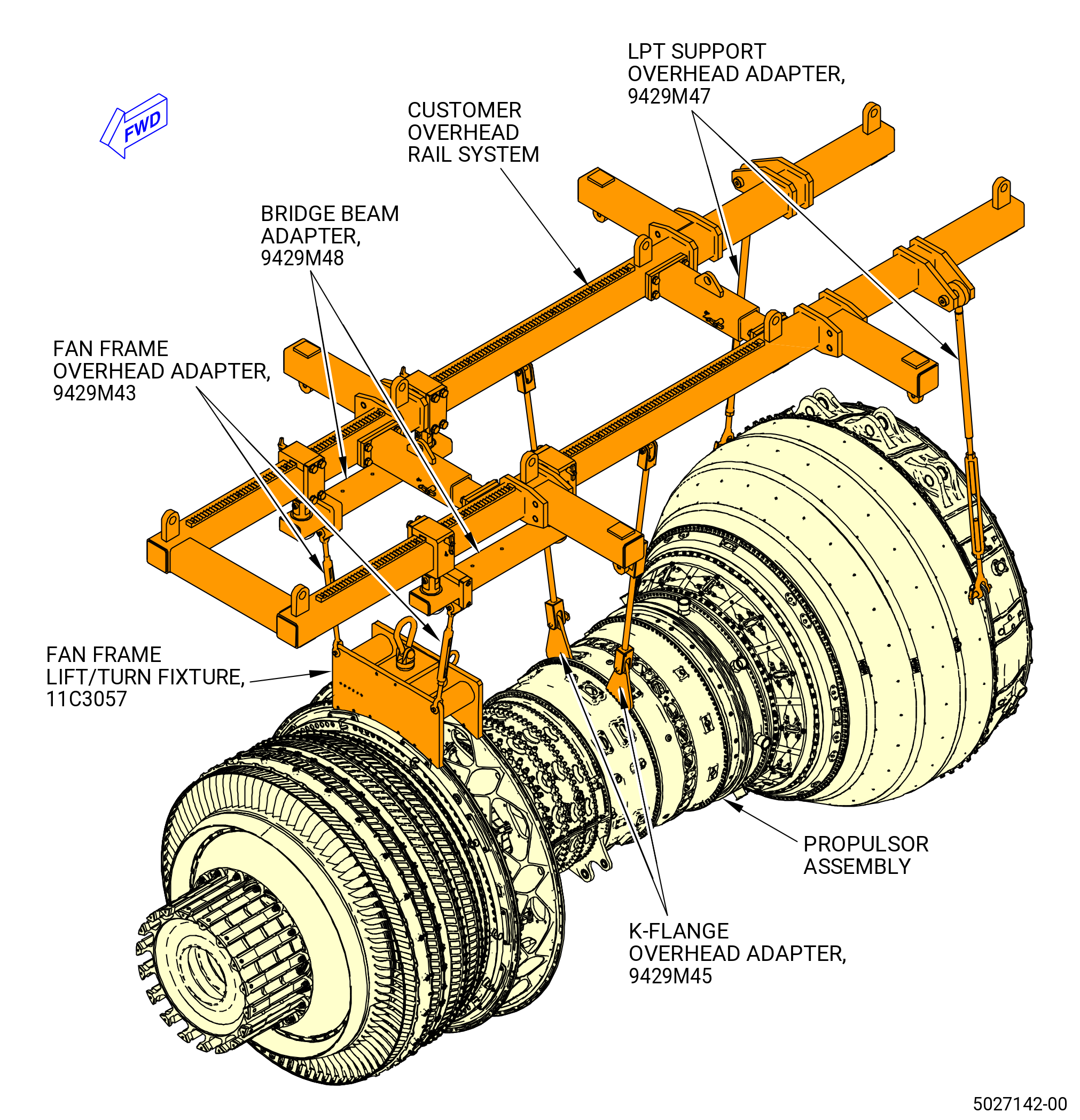
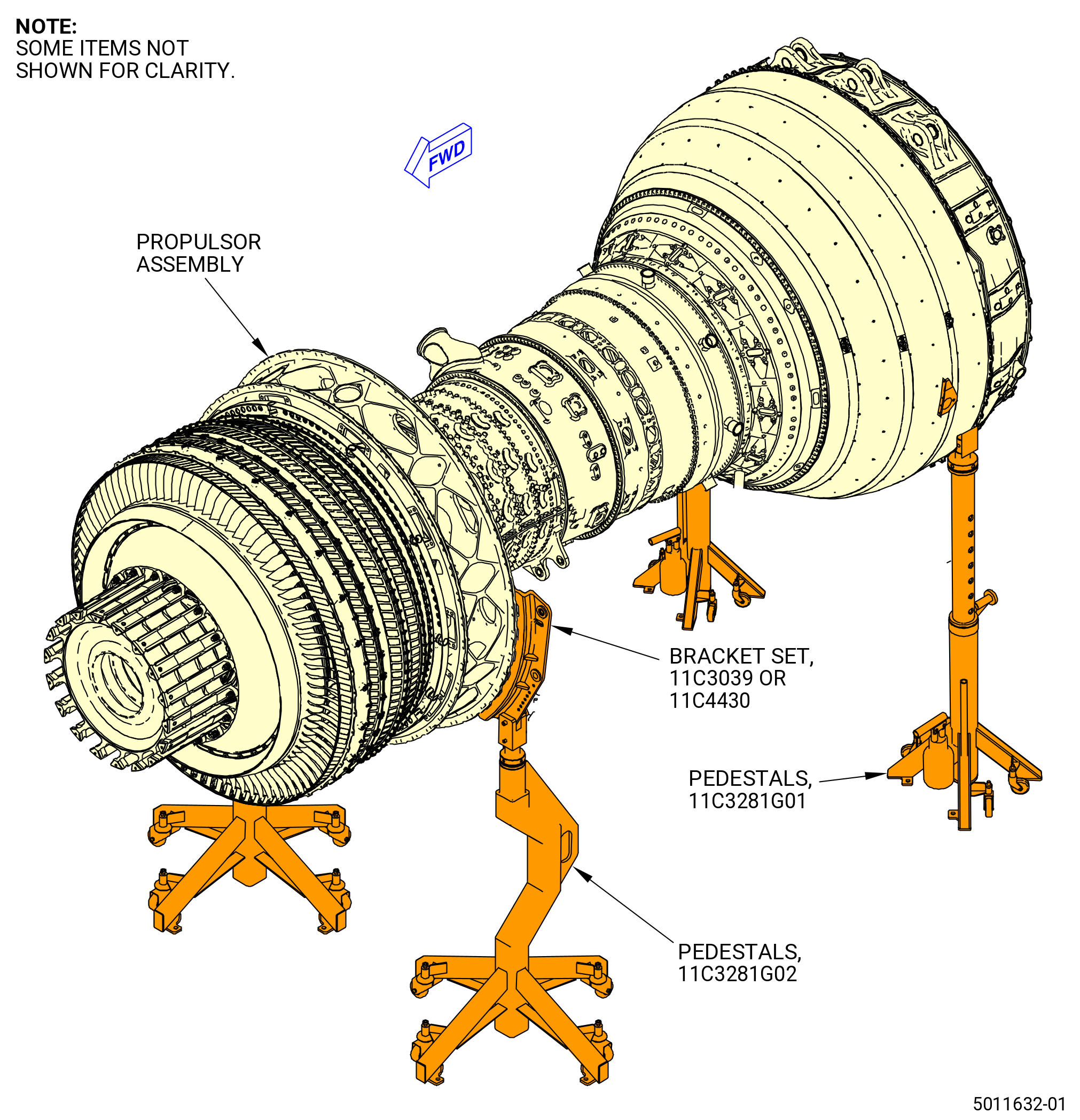
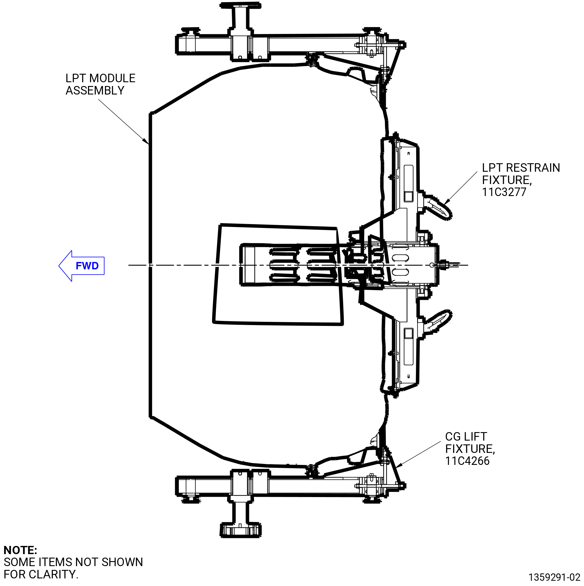
| C. | This procedure starts with the engine in the horizontal position, installed in the 11C3044 engine module adapter assembly that hangs from the customer overhead rail system or supported by the 11C3281 pedestals at the equivalent disassembly status of TASK 72-00-02-030-804 (72-00-02, DISASSEMBLY 004) . Refer to Figure 302 and Figure 303. |
| D. | Use this procedure to remove the LPT and mid fan shaft module assemblies only. For complete engine disassembly, refer to TASK 72-00-00-030-801 (72-00-00, DISASSEMBLY 001) . |
| E. | Before you do this procedure, read the assembly and disassembly techniques section. Refer to TASK 70-10-00-800-009 (ASSEMBLY AND DISASSEMBLY TECHNIQUES) . |
| F. | Make sure that you follow the instructions carefully and know the special tools usage before you remove the LPT module. |
| G. | Tag parts for special inspection if the LPT module was operated in unusual conditions. |
| H. | Make sure that the engine and the LPT module have the correct support at all times to prevent injury to personnel or damage to engine parts. |
| 2 . | Tools, Equipment, and Materials. |
| NOTE: |
|
| A. | Tools and Equipment. |
| (1) | Special Tools. |
| (2) | Standard Tools and Equipment. |
|
| (3) | Locally Manufactured Tools. None. |
| B. | Consumable Materials. |
|
| C. | Referenced Procedures. |
|
| D. | Expendable Parts. None |
| * * * FOR ALL |
| * * * FOR ALL |
| * * * FOR ALL |
| 3 . | Procedure. |
| Subtask 72-00-04-020-001 |
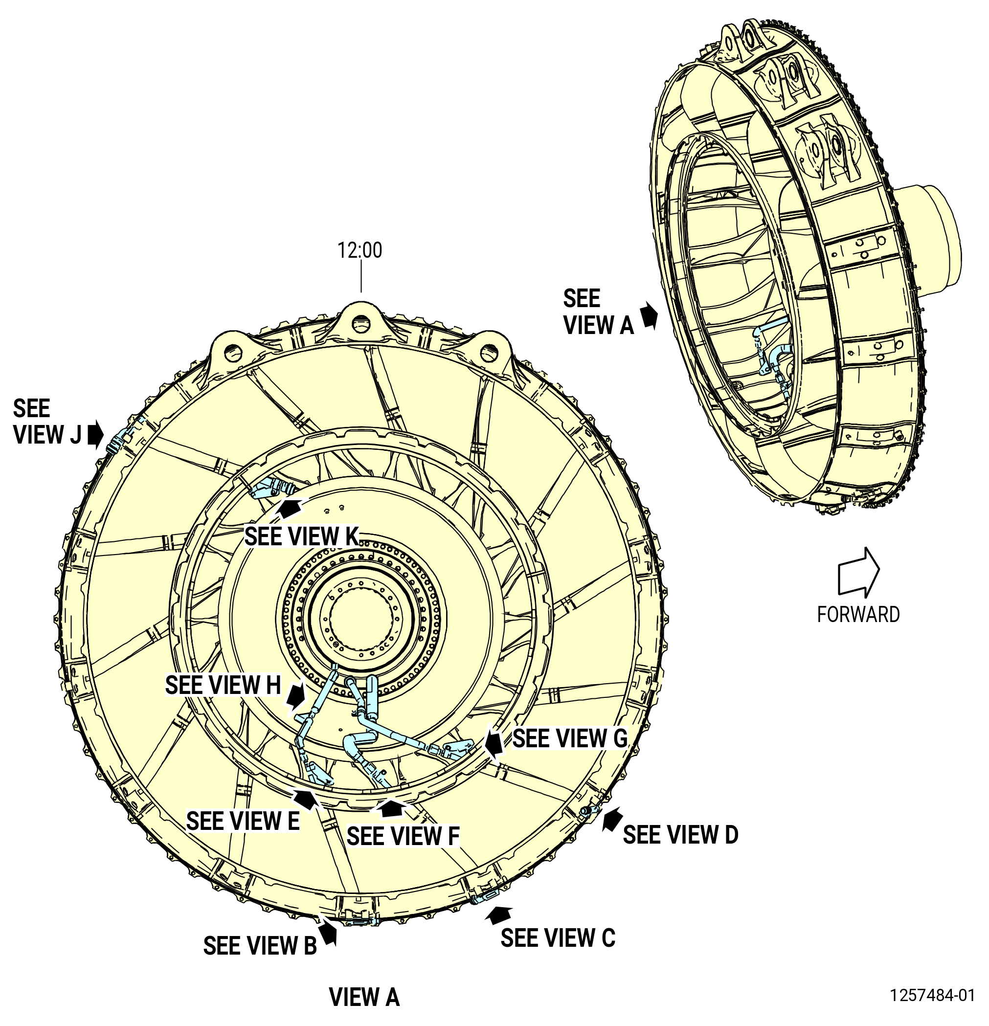
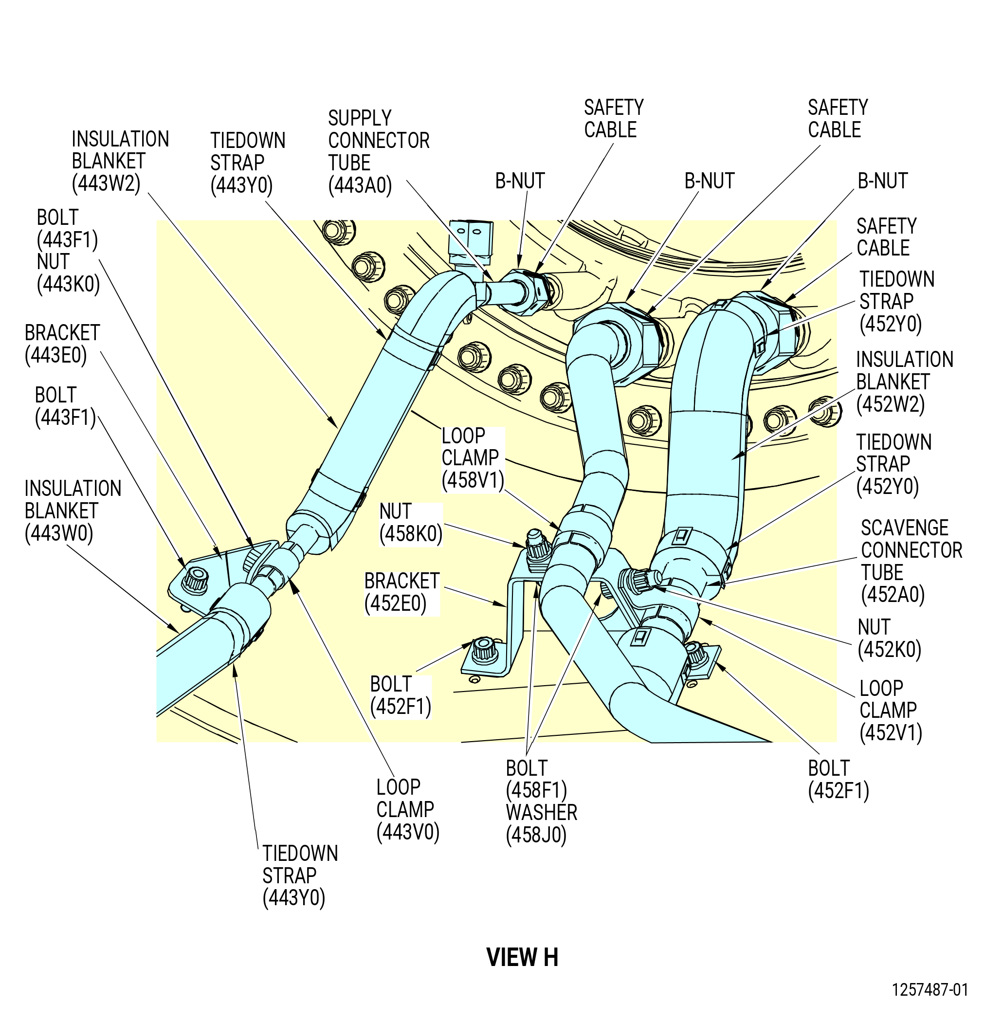
| A. | Remove the aft sump piping as follows: |
| (1) | Remove the connector supply tube 2 (supply tube 2) (443A2) and connector supply tube 3 (supply tube 3) (443A3) as follows. Refer to Figure 305. |
| (a) | Remove and discard the tiedown straps (strap) (45-200 , 72-00-02) (SIN 443Y0) on the supply 3-1 insulation blanket (insulation blanket) (443W4), supply 3-1 insulation blanket (insulation blanket) (443W5), supply 2-1 insulation blanket (insulation blanket) (443W8), and supply 2-2 insulation blanket (insulation blanket) (443W9). |
| (b) | Remove the insulation blankets from the supply tube 2 and supply tube 3. |
| (c) | Remove the safety wire from the supply tube 2 and supply tube 3 B-connectors. |
| (d) | Remove the supply tube 2 from the connector supply 1 assembly tube (oil supply tube) (443A0). |
| (e) | Remove the supply tube 2 and supply tube 3 from the A/O C-sump cover (C-sump cover) (0150C). |
| Subtask 72-00-04-020-053 |
| * * * FOR ALL |
| (2) | Remove the tie down straps and insulation blankets from the supply connector tube, refer to Figure 304. |
| (3) | Remove the tie down straps and insulation blankets from the scavenge connector tube, refer to Figure 304. |
| Subtask 72-00-04-020-054 |
| * * * FOR ALL |
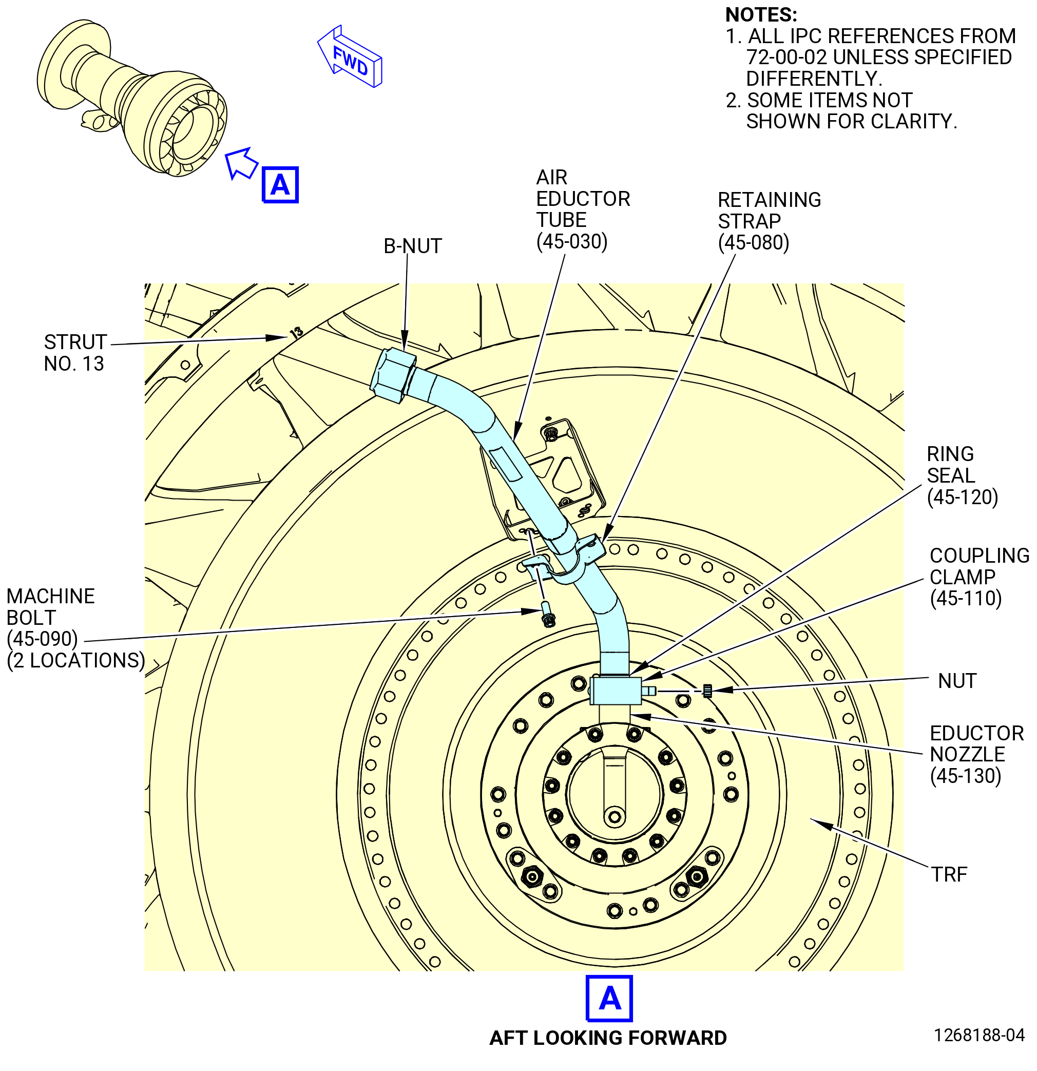
| (4) | Remove the air eductor tube (61BA1) from the TRF No. 13 strut as follows. Refer to Figure 306. |
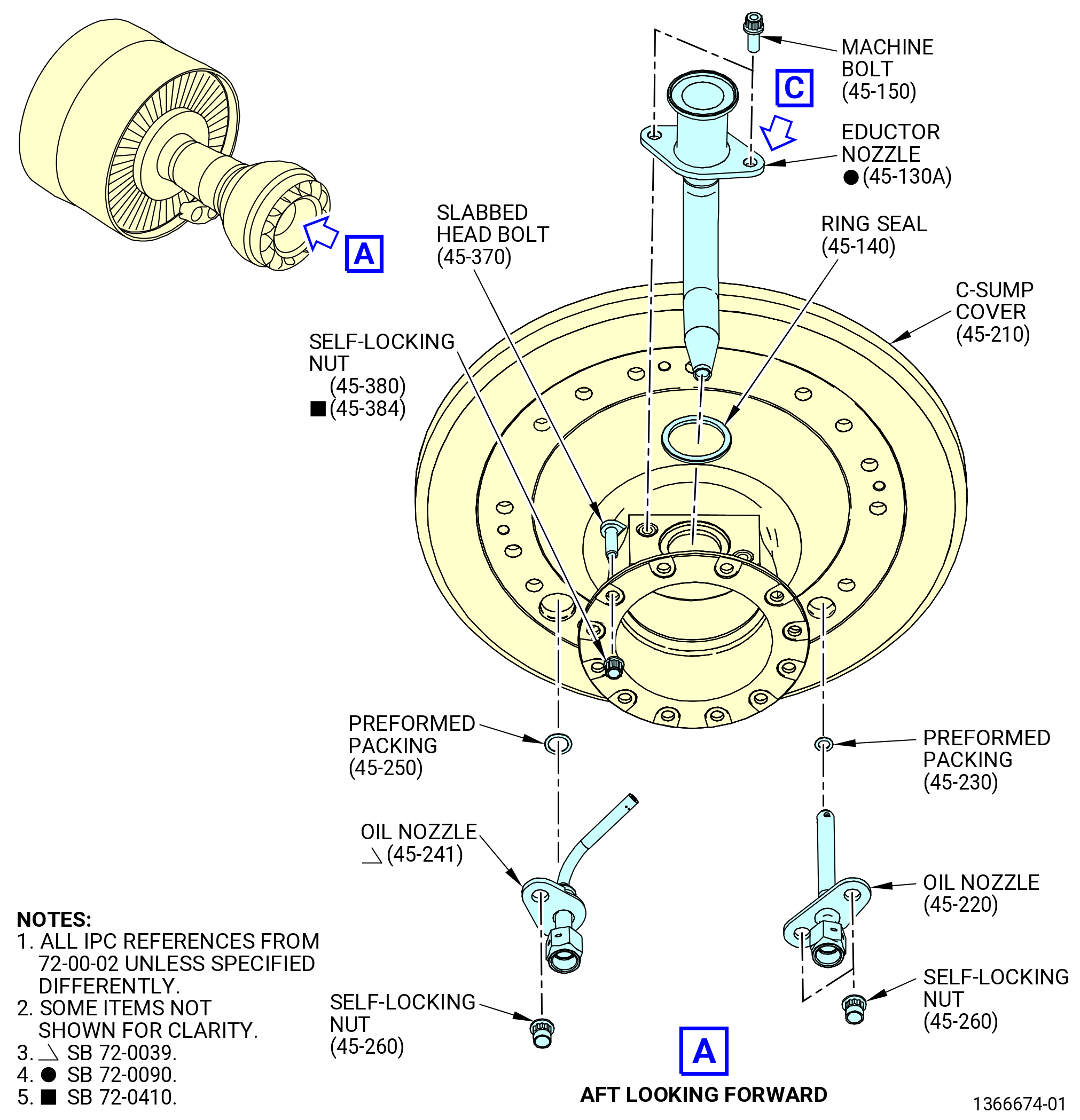
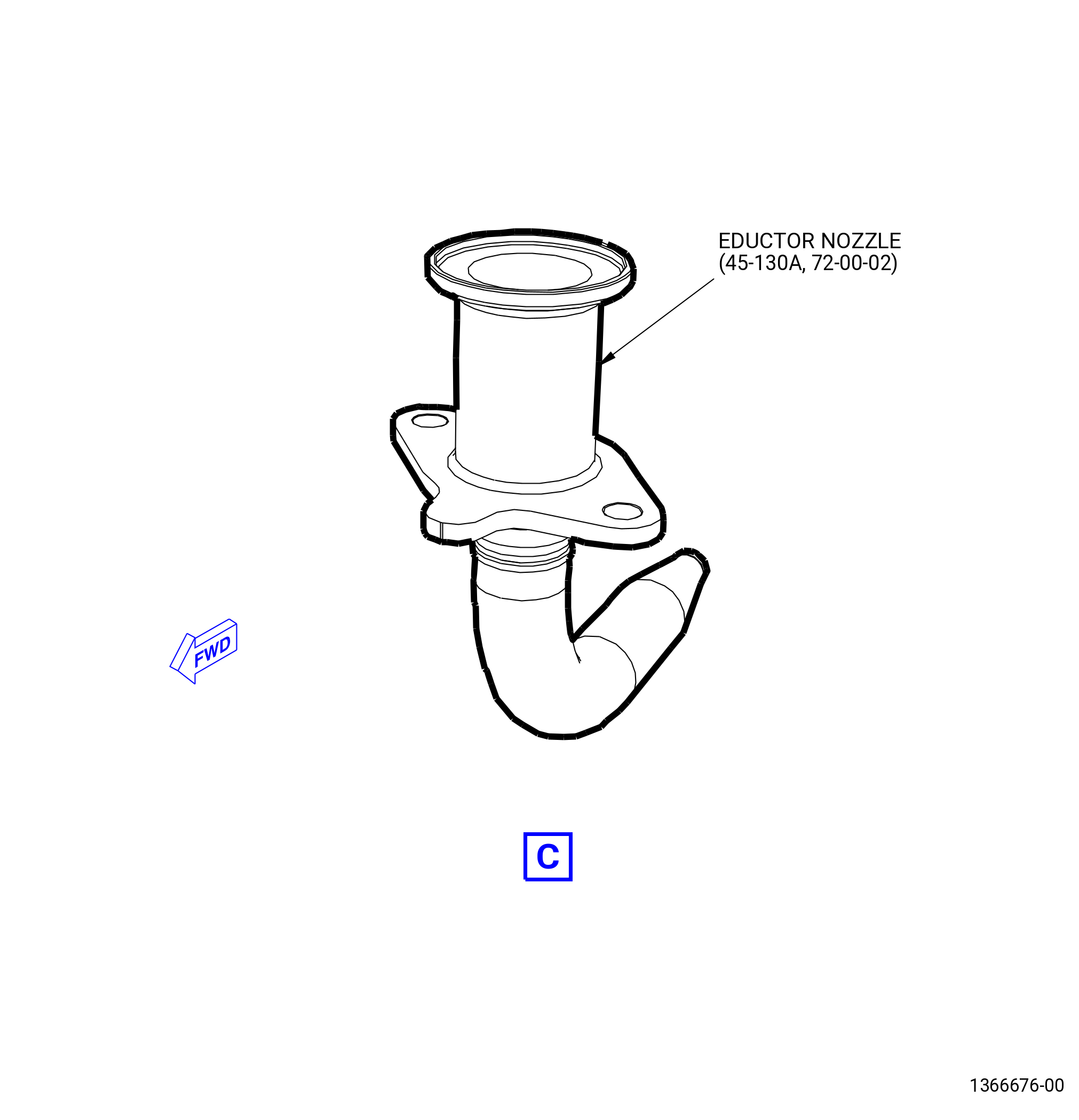
| (a) | Remove the nut from the coupling clamp (61BV1) on the eductor nozzle (45-130 , 72-00-02) (SIN 015K3) or (45-130A , 72-00-02) (SIN 015K3). |
| (b) | Loosen the B-nut on the air eductor tube. |
| (c) | Remove the machine bolts (61BF4) and the retaining strap (61BV0) from the support bracket (61BE2). |
| (d) | Remove the air eductor tube and the ring seal (45-120 , 72-00-02) (SIN 61BN0). Discard the ring seal. |
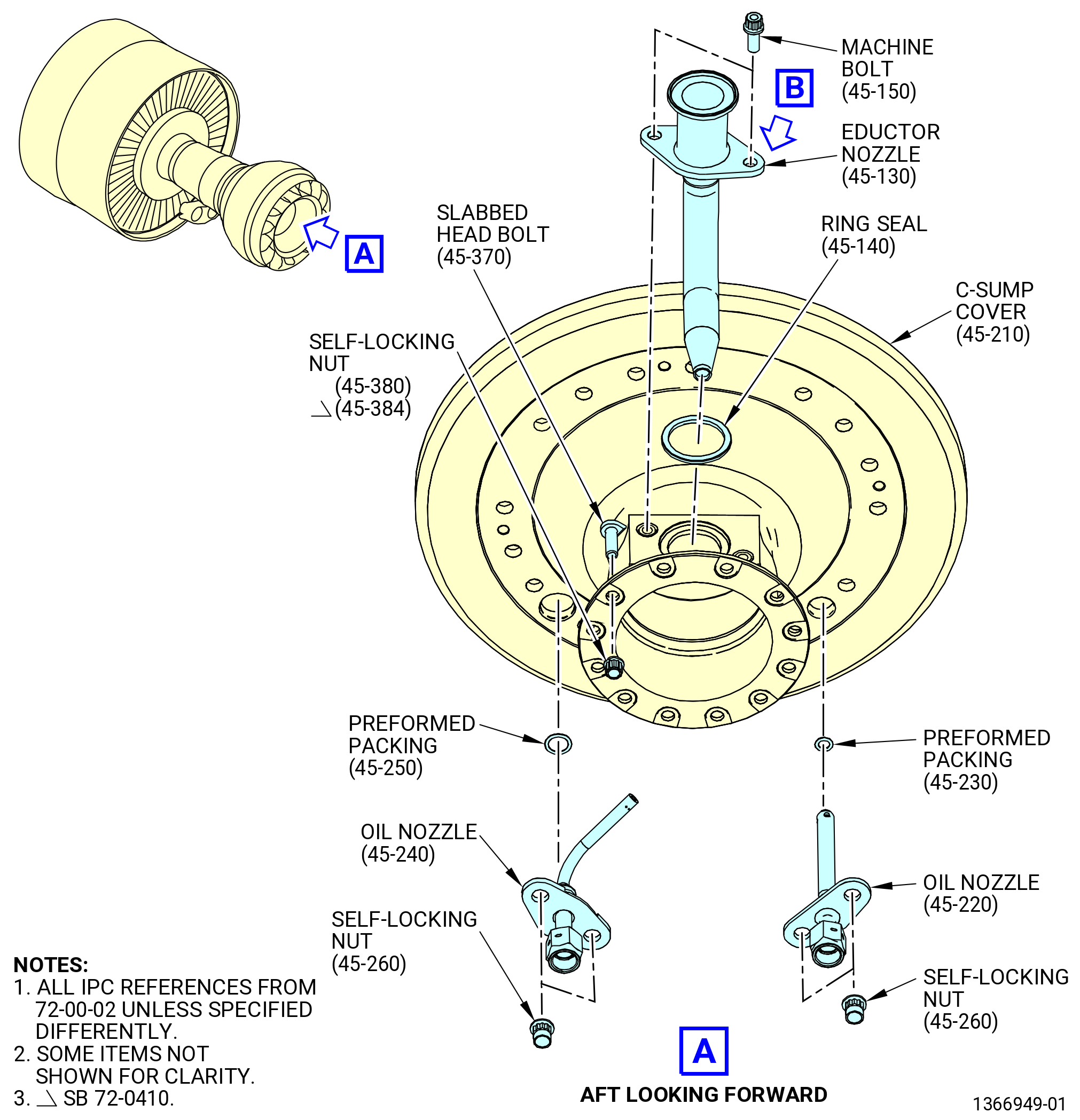
| (5) | Remove the machine bolts (015F1) and the eductor nozzle from the C-sump cover as follows. Refer to Figure 307. |
| (a) | Loosen and remove the two machine bolts that attach the eductor nozzle to the C-sump cover. |
| (b) | Remove the eductor nozzle from the ring seal (45-140 , 72-00-02) (SIN 015K4) and out of the opening of the C-sump cover. |
| (c) | Remove the ring seal (45-140 , 72-00-02) (SIN 015K4) from its position on the opening on the aft end of the C-sump cover. Discard the ring seal. |
| (d) | Loosen the 12 self-locking nuts (45-380 , 72-00-02) (SIN 912K1) or (45-384 , 72-00-02) (SIN 912K1) and remove the push on nuts (45-480 , 72-00-02) (SIN 912K0) and machine bolts from the aft flange of the C-sump cover. |
| NOTE: |
|
| Subtask 72-00-04-020-055 |
| * * * FOR ALL |
| * * * FOR |
| * * * PRE SB 72-0039( Old Oil Nozzle Design ) |
| (6) | Remove the oil nozzles as follows: |
| (a) | Loosen and remove the four self-locking nuts (01544) that attach the A/O No. 5 nozzle (oil nozzle) (01509) and the A/O seal nozzle (oil nozzle) (45-240 , 72-00-02) to the studs and C-sump cover. |
| (b) | Remove the two oil nozzles from the 5:00 o'clock and 7:00 o'clock positions aft looking forward (ALF). |
| (c) | Remove the preformed packings (45-250 , 72-00-02) (SIN 0155B) and (45-230 , 72-00-02) (SIN 01555) from each oil nozzle. Discard the preformed packings. |
| * * * FOR |
| * * * END PRE SB 72-0039 |
| Subtask 72-00-04-020-056 |
| * * * FOR ALL |
| * * * FOR |
| * * * SB 72-0039( New Oil Nozzle Design ) |
| (6).A. | Remove the oil nozzles as follows: |
| (a) | Loosen and remove the three self-locking nuts (01544) that attach the oil nozzle (01509) and the oil nozzle (45-241 , 72-00-02) to the studs and C-sump cover. |
| (b) | Remove the two oil nozzles from the 5:00 o'clock and 7:00 o'clock positions aft looking forward (ALF). |
| (c) | Remove the preformed packings (45-250 , 72-00-02) (SIN 0155B) and (45-230 , 72-00-02) (SIN 01555) from each oil nozzle. Discard the preformed packings. |
| * * * FOR |
| * * * END SB 72-0039 |
| * * * FOR ALL |
| * * * FOR ALL |
| * * * FOR ALL |
| * * * FOR ALL |
|
|
| Subtask 72-00-04-020-003 |
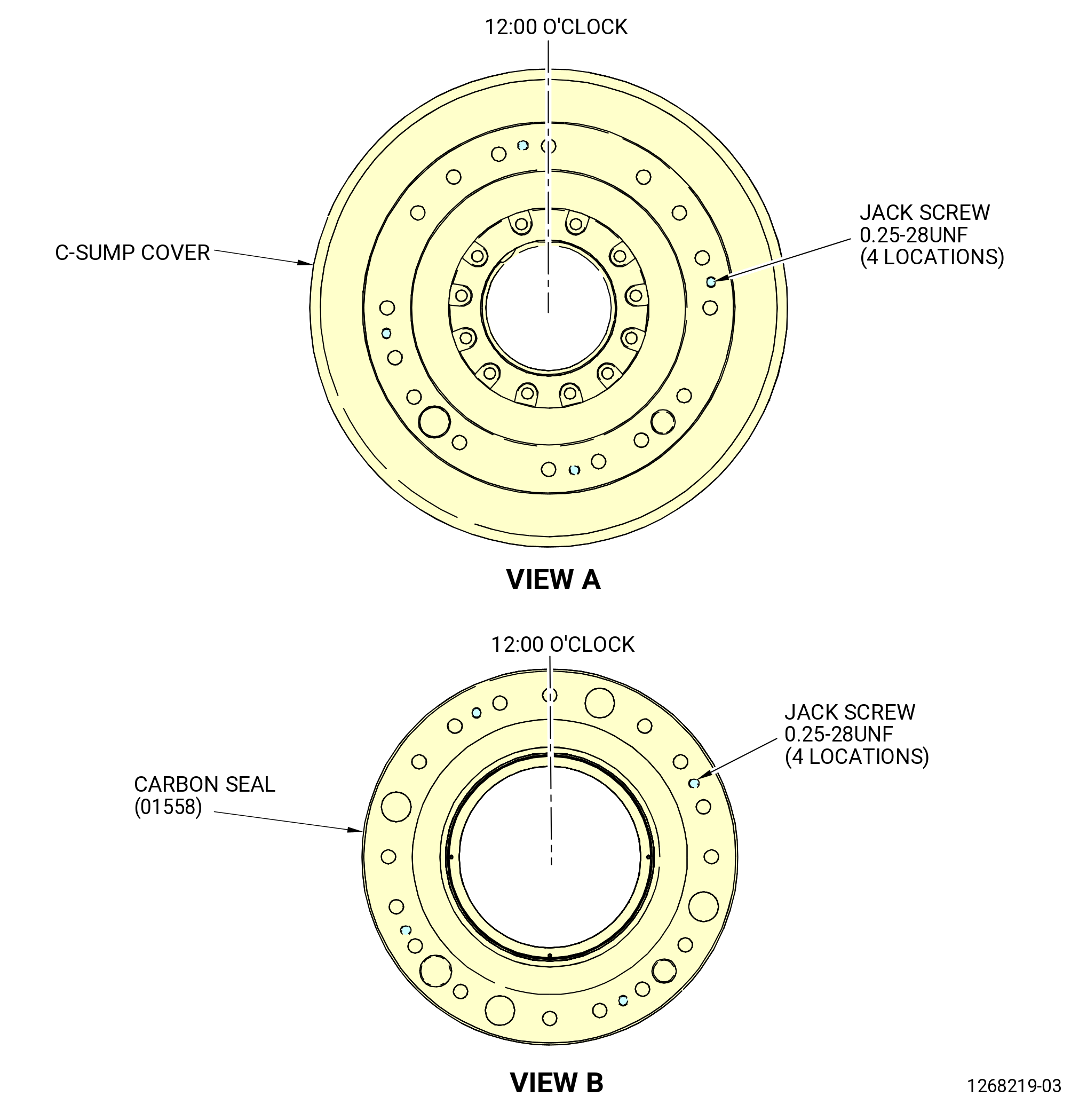
| (7) | Remove the C-sump cover (0150C) and the No. 5 bearing carbon seal (carbon seal) (01558) as follows. Refer to Figure 308. |
| (a) | Remove the remaining self-locking nuts (01544) that attach the forward flange of the C-sump cover to the No. 5 bearing housing (bearing housing) (01501). |
| (b) | Install the jack screws, 0.25-28UNF, at four equally spaced 90-degree locations on the forward flange of the C-sump cover. |
| (c) | Apply an equal quantity of turns to the jack screws to remove the C-sump cover. |
| (d) | Remove and discard the seal ring (45-360 , 72-00-02) (SIN 01550) from the forward side of the C-sump cover. |
| (e) | Install the jack screws, 0.25-28UNF, at four equally spaced 90-degree locations on the forward flange of the carbon seal. |
| CAUTION: |
|
| (f) | Apply an equal quantity of turns to the jack screws to remove the carbon seal. |
| (g) | Remove and discard the preformed packing (45-340 , 72-00-02) (SIN 01551) from the forward side of the carbon seal. |
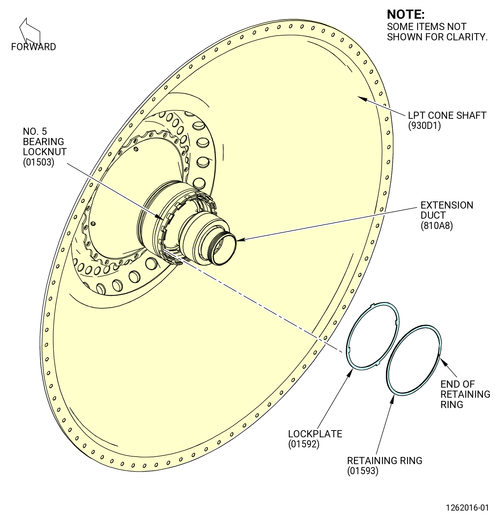
| (8) | Remove the retaining ring (01593) and No. 5 bearing lock plate (lock plate) (01592) from the No. 5 bearing lock nut (01503) as follows. Refer to Figure 309. |
| (a) | Remove the retaining ring from the groove inside the castellations of the No. 5 bearing lock nuts as follows: |
| 1 | Find one end of the retaining ring (where the retaining ring makes an overlap on itself). |
| 2 | Use a pick (or equivalent small, pointy tool) and make contact with the end of the retaining ring. |
| CAUTION: |
|
| 3 | Compress the retaining ring radially in. Move the pick around the outside circumference of the retaining ring. |
| NOTE: |
|
| (b) | Use a pick to remove the No. 5 bearing lock plate (lock plate) (01592) from the slots on the No. 5 bearing locknut and the A/O LPT cone shaft (LPT cone shaft) (930D1). |
| (9) | Measure final Dimension R on the bearing housing and LPT cone shaft as follows: |
| (a) | Measure final Dimension R. Refer to TASK 72-00-04-420-801 (72-00-04, INSTALLATION 001). |
| (b) | Record final Dimension R. Refer to Figure 310. |
| * * * FOR ALL |
| * * * FOR ALL |
| * * * FOR ALL |
| Subtask 72-00-04-020-004 |
| * * * FOR ALL |
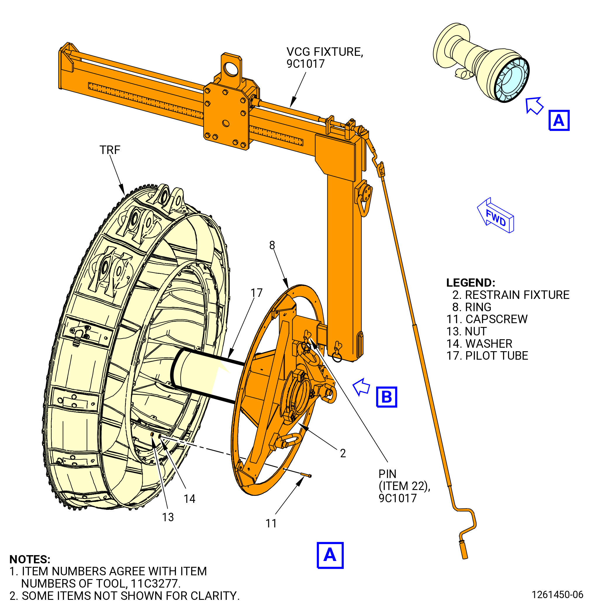
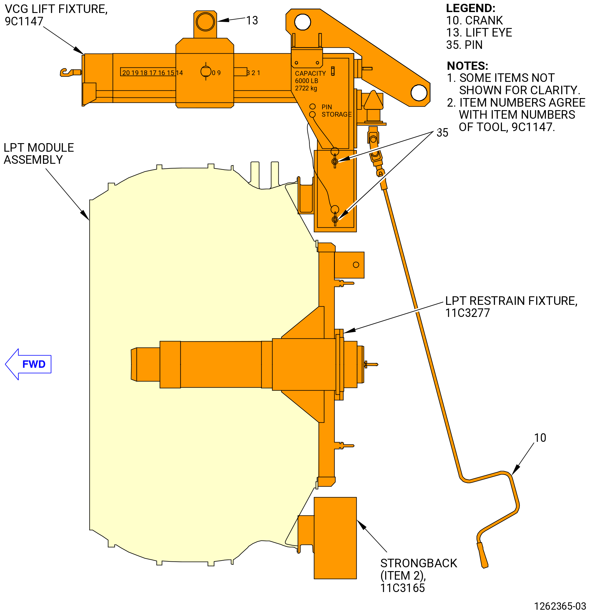
| B. | Install the 11C3277 LPT restrain fixture to the aft side of the TRF inner flange. Refer to Figure 311 and do as follows: |
| WARNING: |
|
| (1) | Attach an overhead hoist to the 9C1017 VCG fixture. |
| (2) | Make sure that the pilot tube (item 17) and nut housing (item 19) of the 11C3277 LPT restrain fixture is removed. |
| (3) | Lift the 9C1017 VCG fixture and attach to the 11C3277 LPT restrain fixture with the pin (item 22) of the VCG fixture. |
| (4) | Lift the 11C3277 LPT restrain fixture and adjust the center of gravity (CG) on the 9C1017 VCG fixture. |
| (5) | Align the ring (item 8) of the 11C3277 LPT restrain fixture to the aft inner flange of the TRF and attach with the capscrew (item 11), the washer (item 14), and the nut (item 13). Install the nut and the washer on the TRF flange. |
| (6) | Remove the 9C1017 VCG fixture from the 11C3277 LPT restrain fixture. |
| Subtask 72-00-04-020-005 |
| * * * FOR ALL |
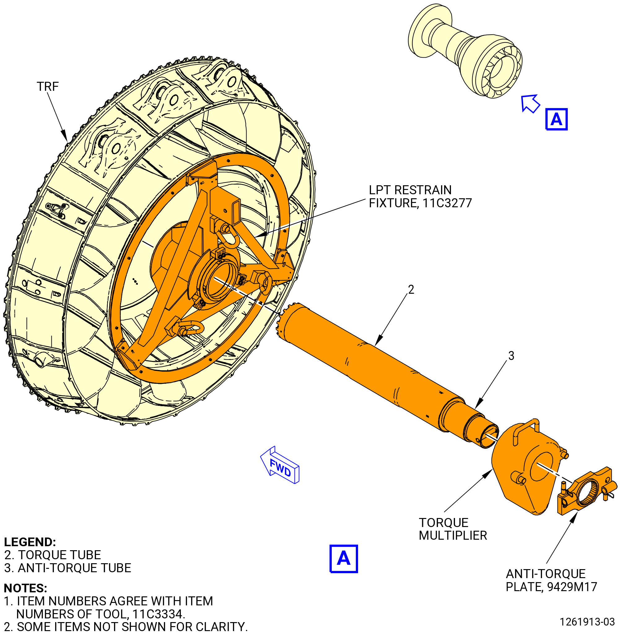
| C. | Install the 11C3334 No. 5 bearing locknut torque fixture as follows. Refer to Figure 312. |
| Subtask 72-00-04-020-045 |
| * * * FOR ALL |
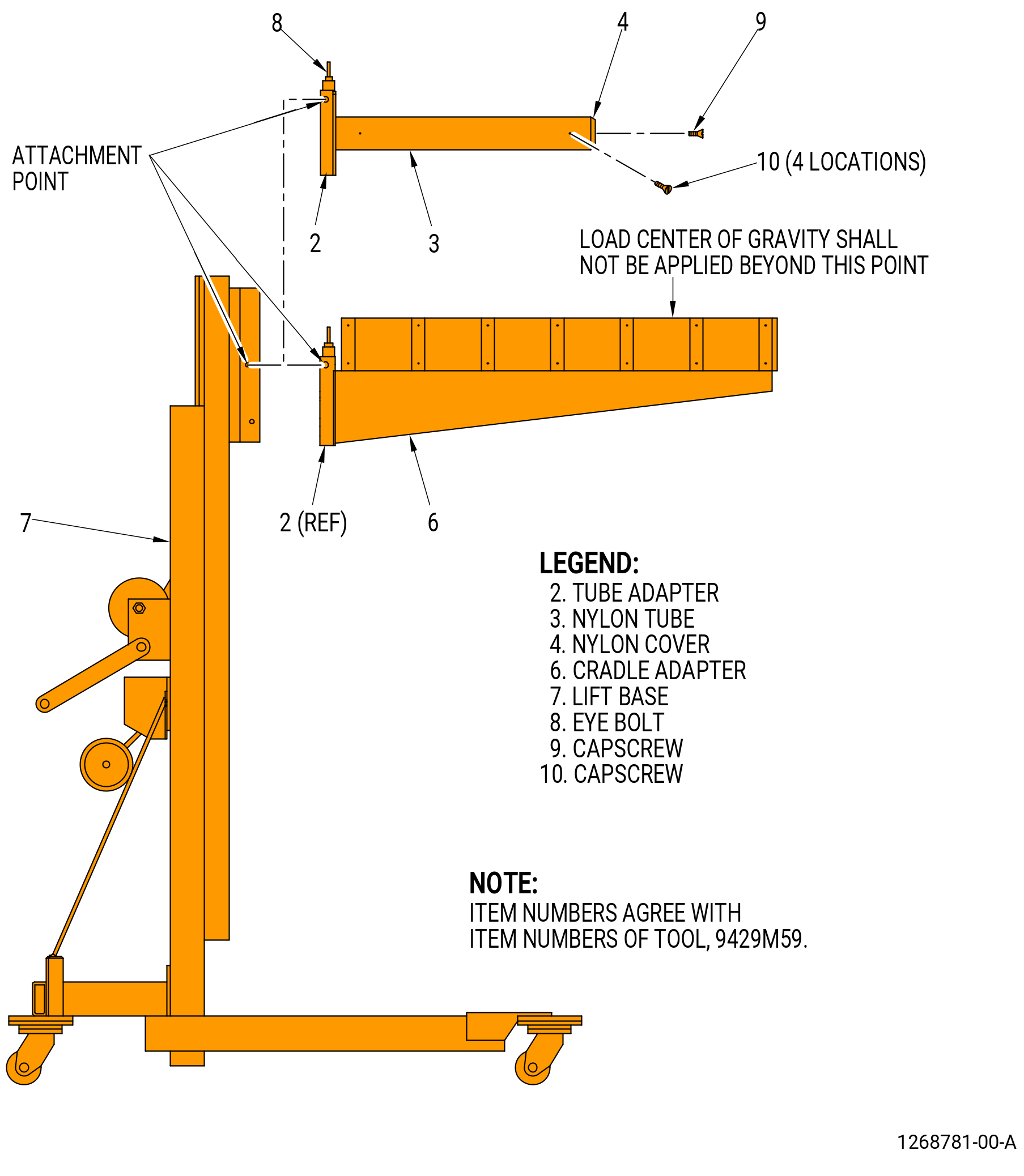
| (1) | Prepare the 9429M59 breach loader as follows. Refer to Figure 313. |
| (a) | Install the cradle adapter (item 6) as follows: |
| 1 | If necessary, remove the nylon tube (item 3) from the tube adapter (item 2). |
| 2 | Attach an overhead hoist to the eye bolt (item 8) on the cradle adapter (item 6). |
| WARNING: |
|
| 3 | Lift the cradle adapter (item 6) and install it on the tube adapter (item 2) and safely attach. |
| (b) | Install the nylon tube (item 3) on the tube adapter (item 2) as follows: |
| 1 | Put the nylon tube (item 3) on the tube adapter (item 2) and secure it with the capscrews (item 10). |
| 2 | Put the nylon cover (item 4) on the tube adapter (item 2) and secure it with the capscrew (item 9). |
| WARNING: |
|
| 3 | Lift the nylon tube (item 3), install it on the tube adapter (item 2), and safely attach. |
| (c) | Attach the tube adapter (item 2) to the lift base (item 7) with the lift base retaining pin. |
| CAUTION: |
|
| (d) | Operate the lift base (item 7) as follows: |
| WARNING: |
|
| 1 | Make sure that you lock the lift base (item 7) to prevent movement of the lift. |
| 2 | Do not lift a load unless there are a minimum of three wraps of cable around the winch drum of the lift base (item 7). |
| Subtask 72-00-04-020-046 |
| * * * FOR ALL |
| WARNING: |
|
| CAUTION: |
|
| (2) | Lift the 11C3334 No. 5 bearing locknut torque fixture with the cradle adapter (item 6) of the 9429M59 breach loader. Refer to Figure 312. |
| (3) | Insert the torque tube (item 2) of the 11C3334 No. 5 bearing locknut torque fixture smoothly into 11C3277 LPT restrain fixture on the engine centerline. |
| (4) | Insert the anti-torque tube (item 3) of the 11C3334 No. 5 bearing locknut torque fixture smoothly into the torque tube (item 2) on the engine centerline. |
| (5) | Install the torque multiplier over the splines of the anti-torque tube (item 3). |
| (6) | Install the 9429M17 anti-torque plate on the splines of the torque tube (item 2). |
| (7) | Operate the torque multiplier and loosen the No. 5 bearing lock nut (01503). |
| (8) | Deleted. |
| (9) | When the No. 5 bearing lock nut is loose, remove the 9429M17 anti-torque plate and the torque multiplier. |
| (10) | Remove the torque tube (item 2) and the anti-torque tube (item 3) of the 11C3334 No. 5 bearing lock nut torque fixture from the 11C3277 LPT restrain fixture. |
| WARNING: |
|
| CAUTION: |
|
| (a) | Lift the 11C3334 No. 5 bearing lock nut torque fixture with the cradle adapter (item 6) of the 9429M59 breach loader. Refer to Subtask 72-00-04-020-045 (paragraph 3.C.(1)). |
| (11) | Use your hand to reach into the LPT cone shaft (390D1) and remove the No. 5 bearing lock nut. |
| * * * FOR ALL |
| Subtask 72-00-04-020-006 |
| * * * FOR ALL |
| D. | Remove the coupling seal nut (01545) as follows. Refer to Figure 314. |
| (1) | Insert the 11C3288 carbon runner seal protector on the No. 5 bearing seal (carbon runner seal) (0155A) to protect it during the steps that follow. Make sure that the seal protector is fully forward. |
| WARNING: |
|
| CAUTION: |
|
| (2) | Lift the 11C5012 spanner nut torque fixture with the cradle adapter (item 6) of the 9429M59 breach loader. Refer to Subtask 72-00-04-020-045 (paragraph 3.C.(1)) to install the cradle adapter. |
| (2).A. | A tool can be lifted by a two-legged sling and lifting device. Place each leg of the sling 12 inches from each end of the tool assembly. |
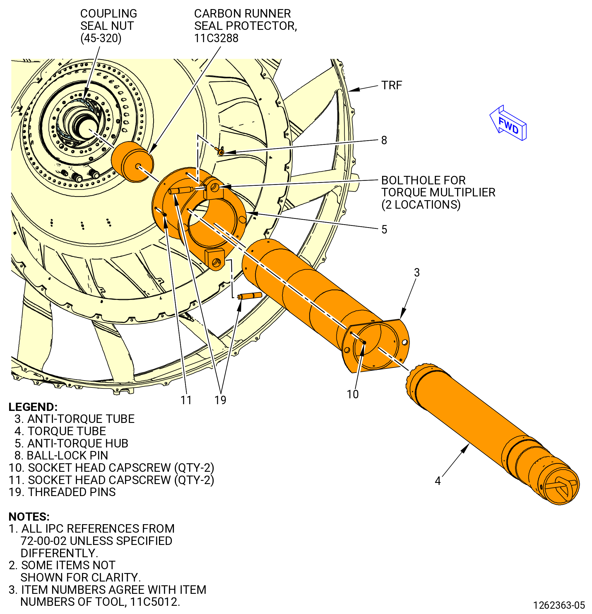
| (3) | Install the 11C5012 spanner nut torque fixture as follows: |
| (a) | Manually install the guide tube (item 18) into the center of the 11C3277 LPT restrain fixture. |
| (b) | Attach the guide tube (item 18) of the 11C5012 spanner nut torque fixture to the 11C3277 LPT restrain fixture with the hex head capscrews (item 15) of the 11C5012 spanner nut torque fixture at six locations. |
| (c) | Carefully insert the shaft assembly (items 3-8,10,13,14,19, and 20) into the guide tube (item 18) until the teeth on the FWD end of anti-torque tube (item 3) engage the slots of the LPT cone shaft assembly. |
| (d) | Attach the anti-torque hub (item 5) to the guide tube (item 18) with two ball-lock pins (item 18) at 3:00 and 9:00 o'clock positions and two bolts (item 11) at 12:00 and 6:00 o'clock. |
| (e) | Push the torque tube (item 4) forward and turn slightly as needed to align castellation with coupling seal nut. |
| (f) | Partially remove the threaded pins (item 19) from the lateral holes in the anti-torque hub (item 5). |
| (g) | With a lifting assistance align the spline of torque multiplier with the spline on torque tube (item 4) and engage the reaction pins with the holes in anti-torque hub (item 5). |
| (h) | Tighten the two threaded pins (item 19) until they contact the reaction pins of the torque multiplier. Confirm torque multiplier is properly restrained. |
| (4) | Operate the torque multiplier and loosen the inner spanner nut. |
| (5) | Deleted. |
| (6) | Remove the 11C5012 spanner nut torque fixture as follows: |
| (a) | Loosen the two threaded pins (item 19) and remove torque multiplier with the aid of appropriate lifting device. |
| (b) | Remove the anti-torque hub (item 5) from guide tube (item 18) by removing two ball-lock pins (item 8) and two bolts (item 11). |
| * * * FOR ALL |
| Subtask 72-00-04-020-036 |
| * * * FOR ALL |
| (c) | With the 9429M59 breach looader or a two-legged sling carefully remove the shaft assembly (items 3-8,10,13,14,19, and 20) from guide tube (item 18). Make sure that certain tool is properly supported while withdrawing. |
| (d) | Remove the guide tube (item 18) of the 11C5012 spanner nut torque fixture from the 11C3277 LPT restrain fixture by removing six hex head capscrews (item 15). |
| (e) | Manually remove the coupling seal nut (01545). |
| (7) | Remove the 11C3288 carbon runner seal protector by pulling it aft. |
| (8) | Remove the 11C3277 LPT restrain fixture as follows. Refer to Figure 311. |
| WARNING: |
|
| (a) | Attach an overhead hoist to the 9C1017 VCG fixture. |
| (b) | Lift the 9C1017 VCG fixture and attach to the 11C3277 LPT restrain fixture with the pin (item 22) of the VCG fixture. |
| (c) | Remove the nut (item 13), washer (item 14), and capscrew (item 11) from the ring (item 8) of the 11C3277 LPT restrain fixture and the aft inner flange of the TRF. |
| (d) | Remove the 11C3277 LPT restrain fixture from the TRF. |
| Subtask 72-00-04-020-007 |
| * * * FOR ALL |
| E. | Remove the No. 5 bearing carbon seal runner (carbon runner seal) (0155A) from the bearing housing (01501) as follows: |
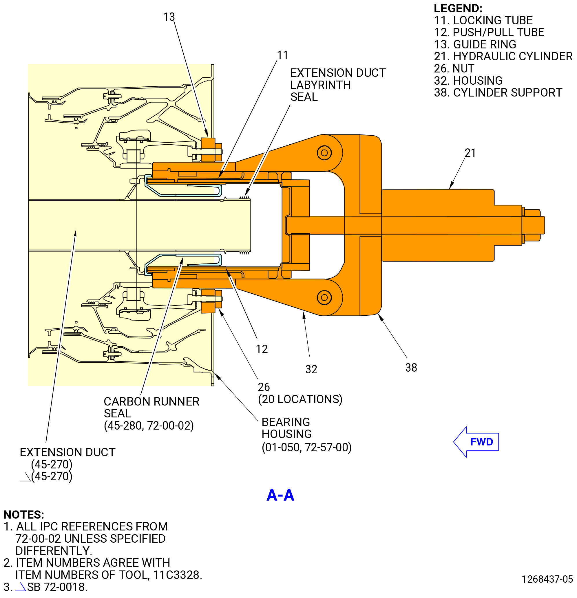
| (1) | Install the 11C3328 air duct extension tool as follows. Refer to Figure 315. |
| CAUTION: |
|
| (a) | Put vinyl-backed tape on the air/oil extension duct (extension duct) (45-270 , 72-00-02) (SIN 810A8) labyrinth seal in the bearing housing (01-050 , 72-57-00) (SIN 01501) to prevent tool damage to the carbon runner seal (45-280 , 72-00-02) (SIN 0155A). |
| (b) | Install the guide ring (item 13) on the studs in the No. 5 bearing aft flange and attach with the nuts (item 26) at 20 locations. |
| (c) | Install the push/pull tube (item 12) so the tabs at the forward end of the tube go through the slots in the forward outer rail of the carbon seal runner. |
| (d) | Turn the push/pull tube (item 12) one-half tooth spacing. Slide the locking tube (item 11) forward to engage the two tabs on the forward end into the slots in the carbon seal runner. |
| (e) | Install the housing (item 32) into the guide ring (item 13). Turn the housing clockwise (CW) by hand to thread the housing (item 32) on the LPT cone shaft (390D1). |
| (f) | Install the cylinder support (item 38) and attach with the ball-lock pins (item 19). |
| (g) | Attach a hydraulic hand pump to the coupler (item 22) on the hydraulic cylinder (item 21) and fully collapse the piston. |
| (h) | Install the hydraulic cylinder (item 21) over the rod on the push/pull tube (item 12). Make sure that the piston is turned aft. |
| (i) | Install the nut (item 25) and washer (item 27) to the push/pull tube (item 12) rod until they are against the hydraulic cylinder (item 21). |
| WARNING: |
|
| CAUTION: |
|
| (j) | Apply hydraulic pump pressure until the seal runner is loose. |
| (k) | Disconnect the hydraulic hand pump from the coupler (item 22) on the hydraulic cylinder (item 21). |
| (l) | Remove the nut (item 25) and the washer (item 27) from the rod on the push/pull tube (item 12). |
| (m) | Remove the hydraulic cylinder (item 21) from the rod on the push pull/tube (item 12). |
| (n) | Remove the ball lock pins (item 19) at two locations and remove the cylinder support (item 38). |
| (o) | Remove the push/pull tube (item 12) with the seal runner. |
| (p) | Slide the sleeve aft from the slots in the carbon runner seal to disengage the two tabs on the forward end of the locking tube (item 11). Then hold the seal runner and turn it counterclockwise (CCW) one-half tooth spacing to remove the push/pull tube (item 12). |
| (q) | Remove the Housing (item 32). |
| (r) | Remove the nuts (item 26) and guide ring (item 13) from the No. 5 bearing aft flange. |
| (s) | Remove the seal runner from the extension duct. Remove the vinyl-backed tape. |
| * * * FOR ALL |
| Subtask 72-00-04-020-038 |
| * * * FOR ALL |
| F. | Install the 11C3277 LPT restrain fixture to the aft inner flange of the TRF. Refer to Figure 311 and do as follows: |
| WARNING: |
|
| (1) | Attach an overhead hoist to the 9C1017 VCG fixture. |
| (2) | Lift the 9C1017 VCG fixture and attach to the 11C3277 LPT restrain fixture (item 2) with the pin (item 22) of the VCG fixture. |
| (3) | Lift the 11C3277 LPT restrain fixture and adjust the CG on the 9C1017 VCG fixture. |
| (4) | Align the ring (item 8) of the 11C3277 LPT restrain fixture to the aft inner flange of the TRF and attach with the capscrew (item 11), the washer (item 14), and the nut (item 13). Install the nut and the washer on the TRF flange. |
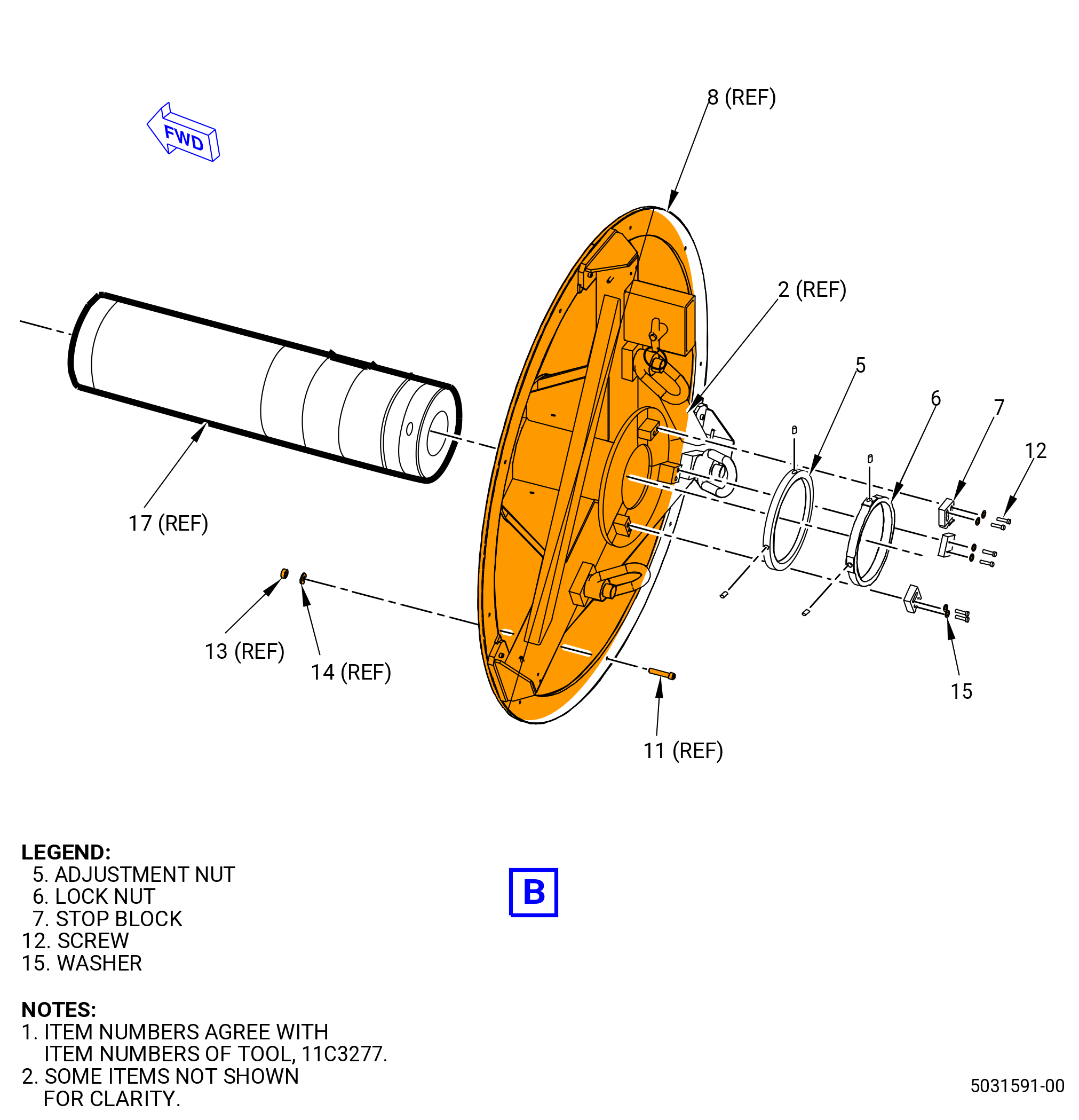
| (5) | Install the pilot tube (item 3) through the restrain fixture (item 2). |
| (6) | Tighten the adjustment nut (item 5) to the aft end of the pilot tube (item 3) until it is against the aft face of the restrain fixture (item 2). |
| (7) | Tighten the locknut (item 6) to the pilot tube (item 3) against the adjustment nut (item 5). |
| (8) | Use the lock washers (item 15) and the screws (item 12) to install the three stop blocks (item 7) on the restrain fixture (item 2) to secure the adjustment nut (item 5). |
| (9) | Remove the 9C1017 VCG fixture from the 11C3277 LPT restrain fixture. |
| Subtask 72-00-04-020-008 |
| * * * FOR ALL |
| G. | Alternative Procedure Available. Install the 11C3165 strongback fixture to the aft outer flange on the TRF as follows: |
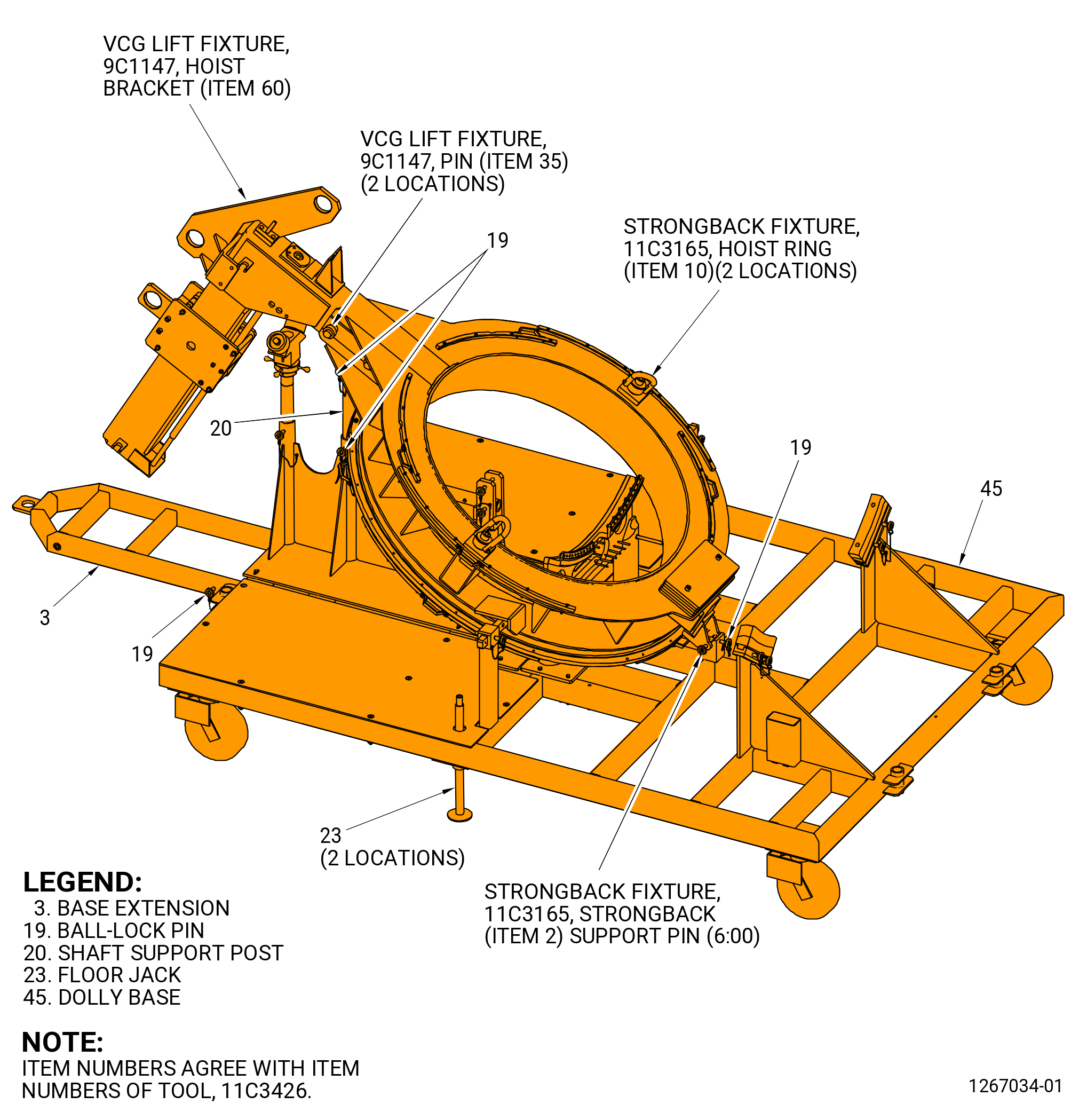
| (1) | Remove the 11C3165 strongback fixture and the 9C1147 VCG lift fixture from the 11C3426 LPT module dolly as follows. Refer to Figure 316. |
| NOTE: |
|
| NOTE: |
|
| CAUTION: |
|
| (a) | Lock the floor locks (item 23) of the 11C3426 LPT module dolly. |
| (b) | Attach a overhead chain hoist to the hoist bracket (item 60) on the 9C1147 VCG lift fixture. |
| (c) | Attach a second overhead chain hoist to the hoist rings (item 10) of the 11C3165 strongback fixture at two locations. |
| WARNING: |
|
| (d) | Use the lift hoists to apply a lift pressure to the 9C1147 VCG lift fixture and the 11C3165 strongback fixture. |
| (e) | Remove the pin (item 19) of the 11C3426 LPT module dolly from the shaft support post (item 20) that secures the strongback fixture to the shaft support post. The strongback can pivot in the strongback (item 2) support pin at the 6:00 o'clock position. |
| (f) | Remove the support pin from the strongback at the 6:00 o'clock position. |
| WARNING: |
|
| (g) | Lift the 11C3165 strongback fixture and the 9C1147 VCG lift fixture from the 11C3426 LPT module dolly in the vertical position. |
| WARNING: |
|
| (2) | Lift the 11C3165 strongback fixture with the 9C1147 VCG lift fixture. |
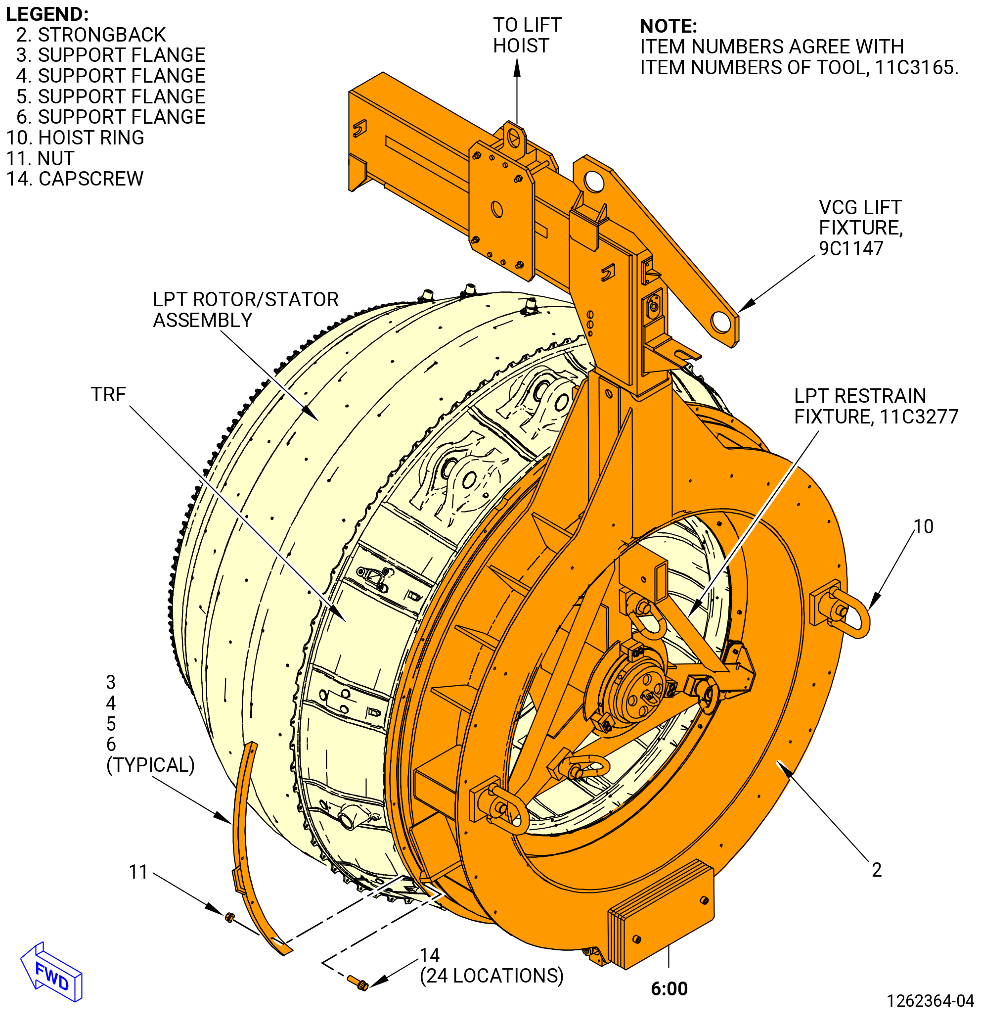
| (3) | Attach the 11C3165 strongback fixture to the TRF as follows. Refer to Figure 317. |
| (a) | Remove the nuts (item 11), the capscrews (item 14), and the flange supports (item 3), (item 4), (item 5), and (item 6) from the flange of the 11C3165 strongback fixture. |
| (b) | Align the top vertical centerline of the strongback flange with the top vertical centerline of the TRF. |
| (c) | Align the bolt holes of the TRF aft outer flange to the strongback forward flange. |
| (d) | Attach the 11C3165 strongback fixture support flanges (item 3), (item 4), (item 5), and (item 6) to the forward side of the TRF aft flange as follows: |
| 1 | Put the first support flange (item 3) on the forward side of the TRF aft flange at the 3:00 o'clock position, ALF. Secure with the capscrews (item 14) and nuts (item 11) at six locations with the nuts installed on the support flange. |
| 2 | Put the second support flange (item 3) on the forward side of the TRF flange at the 9:00 o'clock position ALF. Secure with the capscrews (item 14) and nuts (item 11) at six locations with the nuts installed on the support flange. |
| 3 | Put the support flange (item 4) on the forward side of the TRF flange at the 11:00 o'clock position ALF. Secure with the capscrews (item 14) and nuts (item 11) at four locations with the nuts installed on the support flange. |
| 4 | Put the support flange (item 5) on the forward side of the TRF flange at the 1:00 o'clock position ALF. Secure with the capscrews (item 14) and nuts (item 11) at four locations with the nuts installed on the support flange. |
| 5 | Put the support flange (item 6) on the forward side of the TRF flange at the 6:00 o'clock position ALF. Secure with the capscrews (item 14) and nuts (item 11) at four locations with the nuts installed on the support flange. |
| 6 | Torque the nuts (item 11) to 40-60 lb in. (4.5-6.8 N.m). |
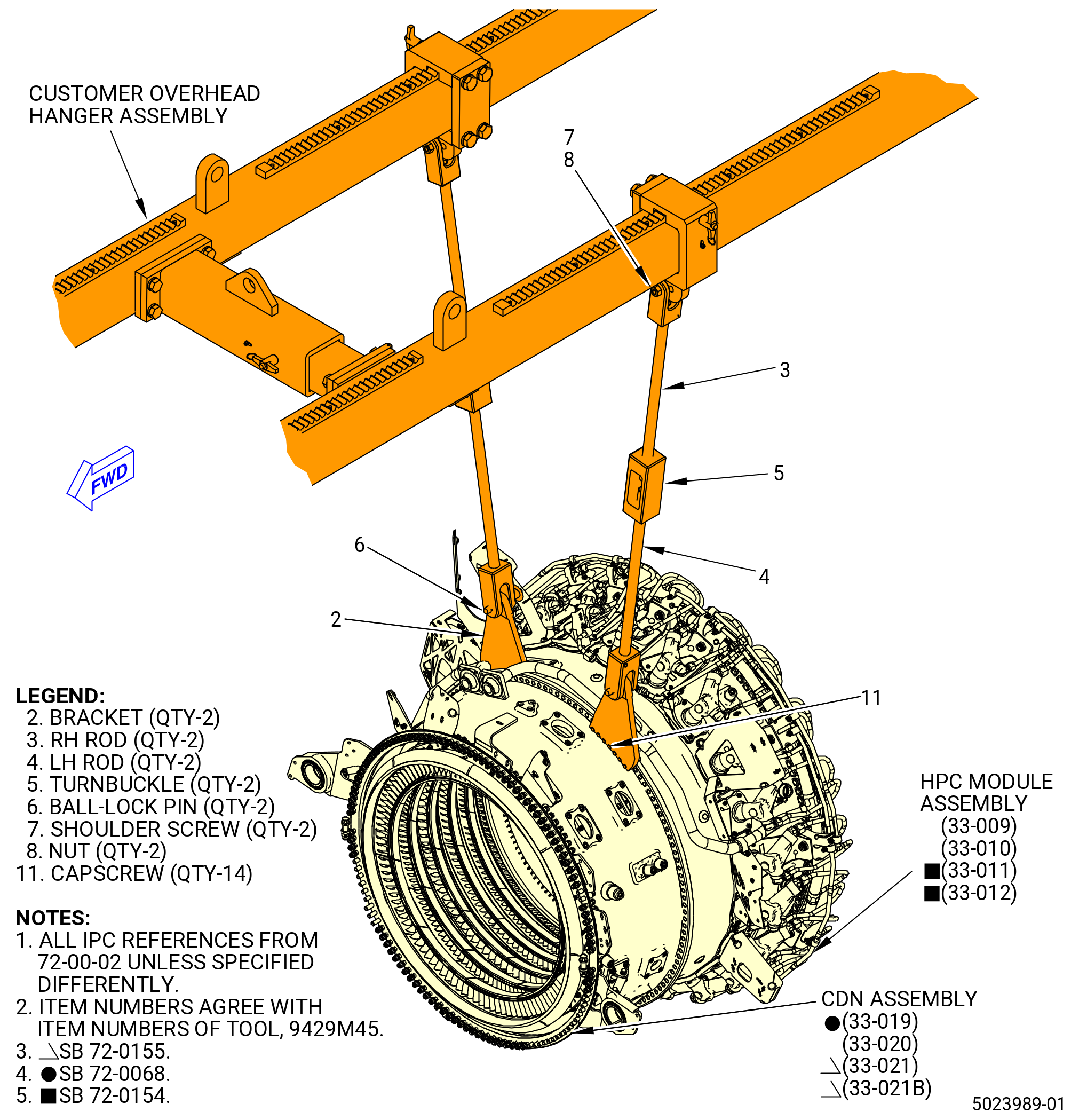
| (4) | Install the 9429M45 K-flange overhead adapter to the propulsor assembly as follows. Refer to Figure 302 and Figure 318. |
| (a) | Re-locate the pedestals to the TCF from the TRF. Refer to TASK 72-00-00-800-803 (72-00-00, SPECIAL PROCEDURE 003). |
| (b) | Attach the right-hand threaded rod (RH rod) (item 3) and the left-hand threaded rod (LH rod) (item 4) to the customer overhead rail system with the shoulder screw (item 7) and the nut (item 8). Tighten the nut against the shoulder screw. |
| NOTE: |
|
| (c) | Remove the screws and the brackets from the combustor diffuser nozzle (CDN) (33-019 , 72-00-02) (SIN 0010A) or (33-020 , 72-00-02) (SIN 0010A) or (33-021 , 72-00-02) (SIN 0010A) or (33-021B , 72-00-02) (SIN 0010A) assembly and the compressor module assembly flange at the boltholes 8-14 and 122-128 ALF. |
| (d) | Install the bracket (item 2) on the right side of the engine on the CDN assembly aft side of the forward flange ALF with the capscrew (item 11) at seven locations. |
| (e) | Install the bracket (item 2) on the left side of the engine to the high pressure compressor (HPC) module assembly (33-009 , 72-00-02) (SIN 00108) or (33-010 , 72-00-02) (SIN 00108) or (33-011 , 72-00-02) (SIN 00108) or (33-012 , 72-00-02) (SIN 00108) forward side of the aft flange ALF with the capscrew (item 11) at seven locations. |
| * * * FOR ALL |
| * * * FOR ALL |
| * * * FOR ALL |
| Subtask 72-00-04-020-050 |
| * * * FOR ALL |
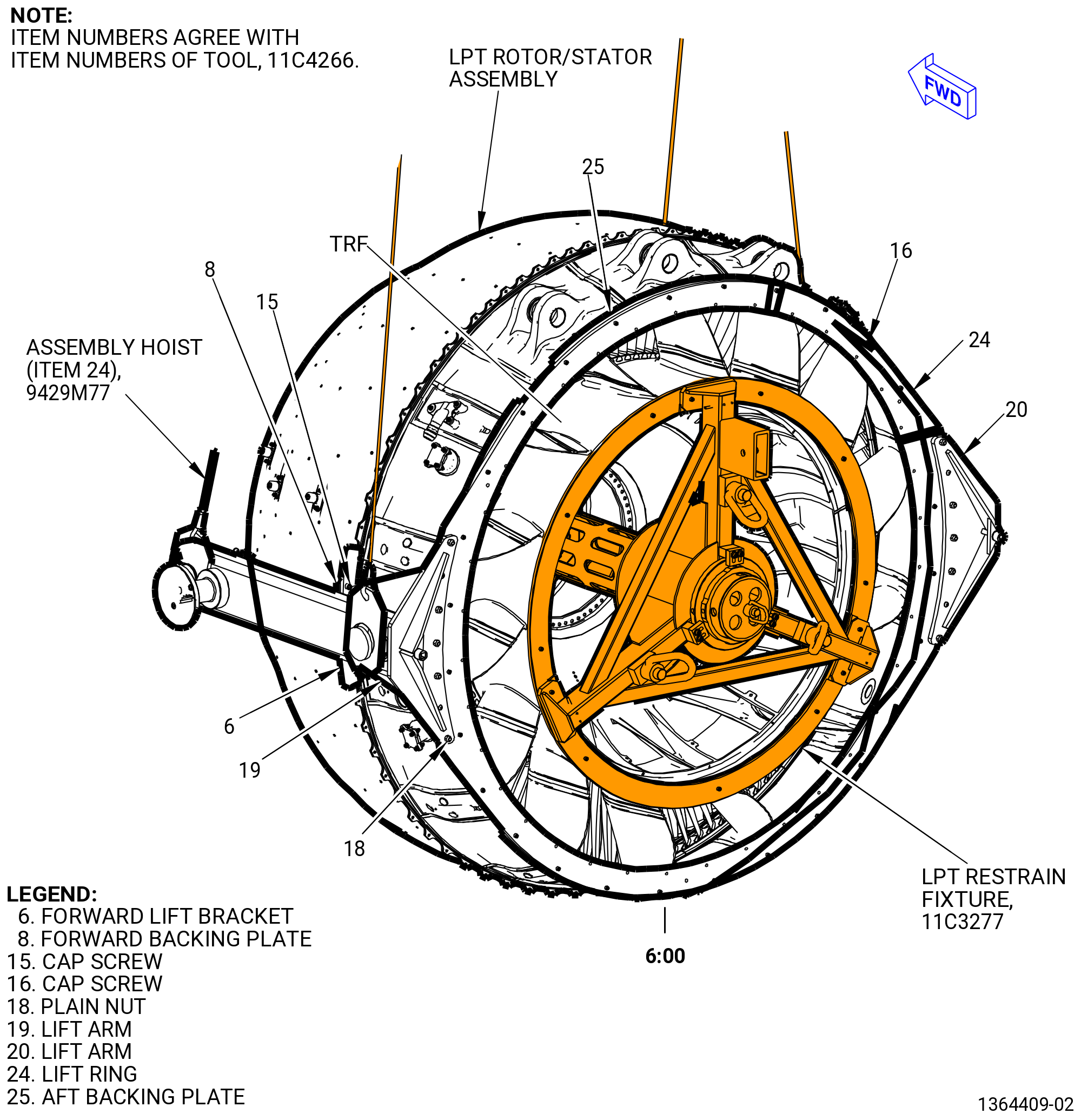
| G.A. | Alternative Procedure. Install the 11C4266 CG lift fixture to the aft outer flange of the TRF. Refer to Figure 319 and do as follows: |
| WARNING: |
|
| (1) | Attach the four assembly hoist (item 24) of the 9429M77 lift and turn fixture to the channel (item 22) of the 9429M77 lift and turn fixture. |
| (2) | Attach the 9429M77 lift and turn fixture to an overhead hoist. |
| (3) | Attach two ends of the assembly hoist (item 24) of the 9429M77 lift and turn fixture to the lift arms (item 19) and (item 20) forward pivot trunnions of the 11C4266 CG lift fixture. |
| (4) | Attach two ends of the assembly hoist (item 24) of the 9429M77 lift and turn fixture to the lift arms (item 19) and (item 20) aft pivot trunnions of the 11C4266 CG lift fixture. |
| (5) | Lift the 11C4266 CG lift fixture and install on the TRF assembly as follows: |
| (a) | Install the lift ring (item 24) on the aft outer flange of the TRF assembly and align the "TOP VERT" marking on the lift ring (item 24) with the top vertical marking of the TRF assembly. |
| NOTE: |
|
| (b) | Install the aft backing plate (item 25) in four equally spaced positions on the forward side of the aft outer flange of the TRF assembly. Use 28 cap screws (item 16) through the holes in the lift ring (item 24) and the aft outer flange of the TRF and into the threaded holes in the four aft backing plates (item 25). |
| (c) | Install the two lift arms (item 19) and (item 20) on the lift ring (item 24). Align the two lift ring (item 24) pins and the 10 lift ring (item 24) threaded rods with the holes in the lift arms (item 19 and item 20). |
| (d) | Attach the 10 plain nuts (item 18) to the lift ring (item 24) threaded rods. |
| (e) | Attach the forward lift brackets (item 6) to each of the lift arms (item 19) and (item 20). Use two cap screws (item 16) in each forward lift bracket (item 6). |
| (f) | Secure the flange of the LPT/TRF assembly to the fwd lift bracket (item 6) with the six cap screws (item 15) that pass through the forward lift bracket (item 6) and the LPT/TRF assembly flanges and into the forward backing plate (item 8). |
| (g) | Remove the 9429M77 lift and turn fixture. |
| * * * FOR ALL |
| Subtask 72-00-04-020-009 |
| * * * FOR ALL |
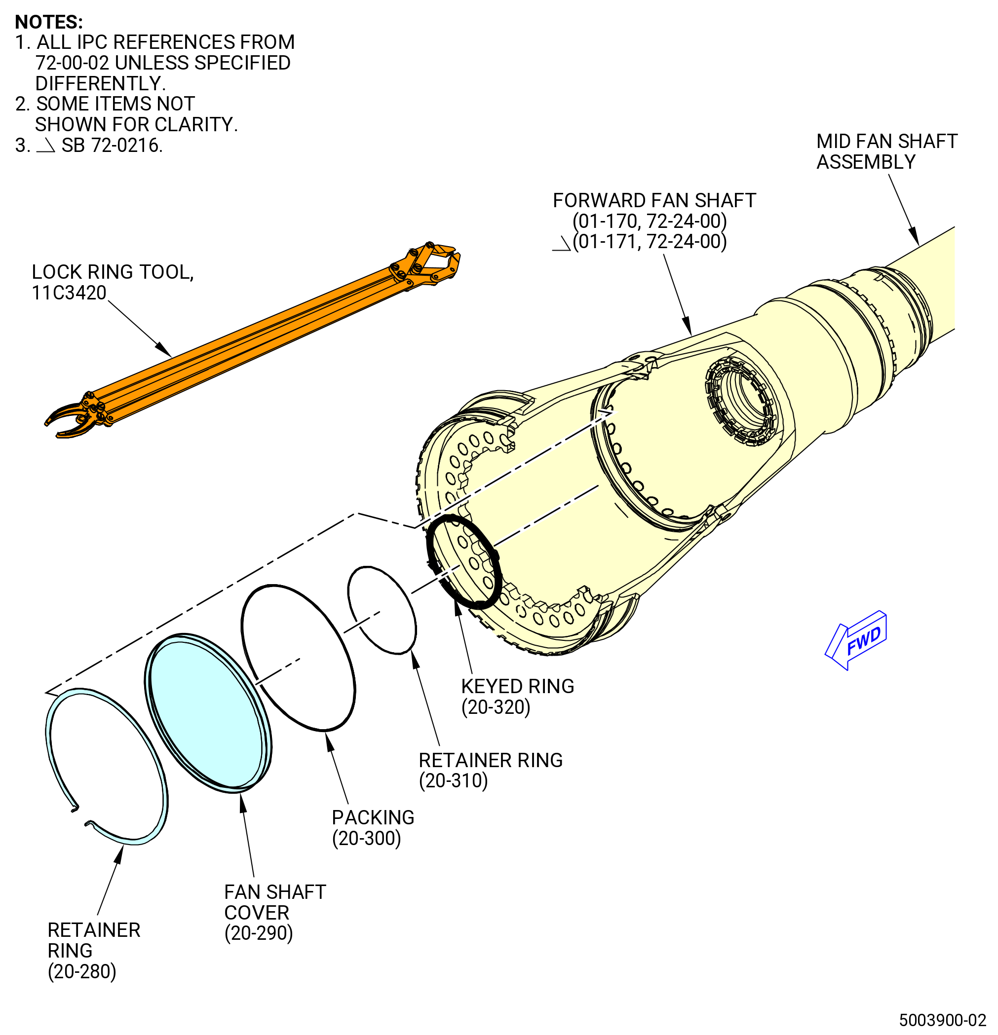
| H. | Remove the fan shaft cover (20-290 , 72-00-02) (SIN 81003) from the forward fan shaft (01-170 , 72-24-00) (SIN 81002) or (01-171 , 72-24-00) (SIN 81002) as follows: |
| NOTE: |
|
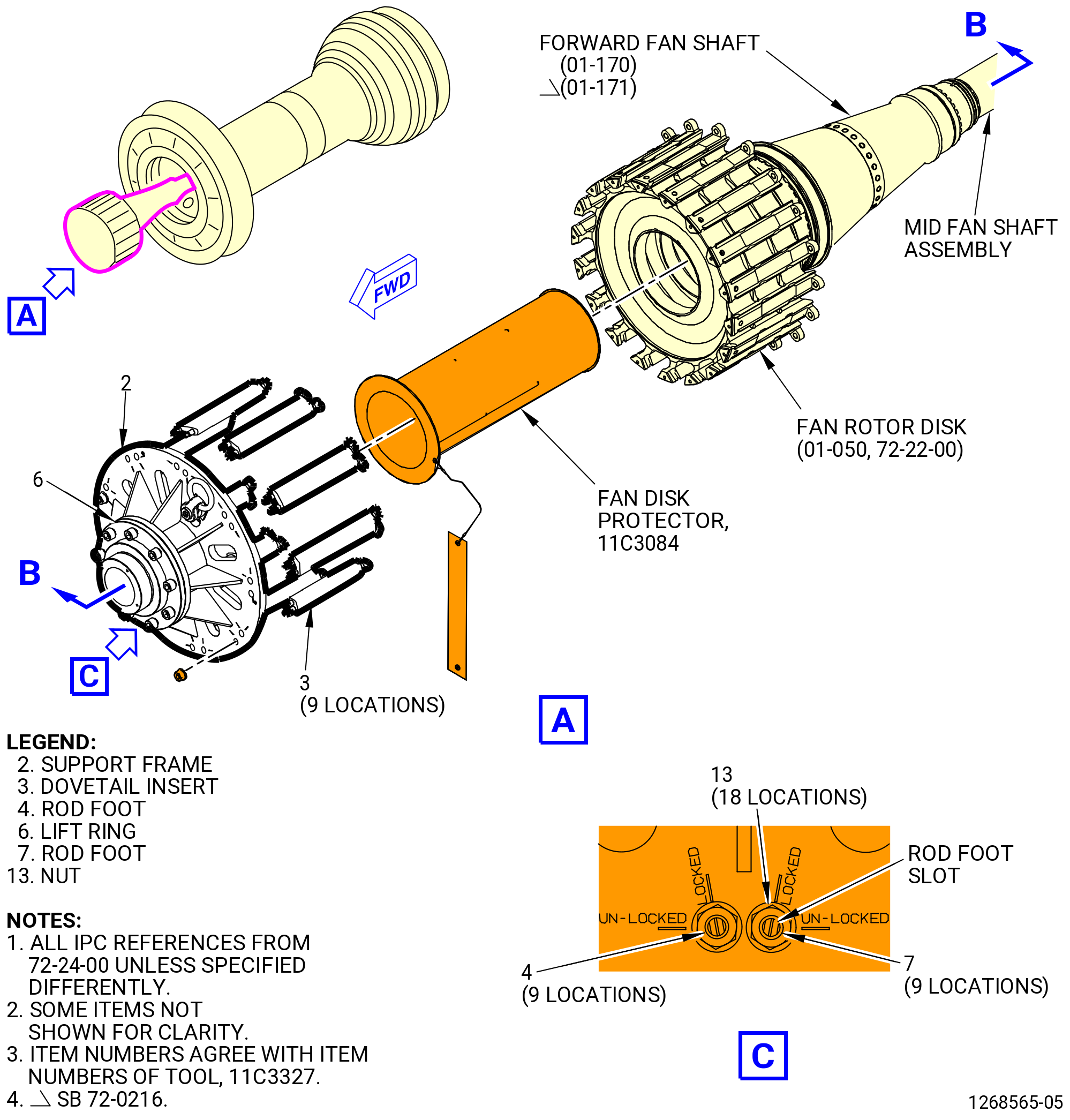
| (1) | Install the 11C3084 fan disk protector into the bore of the fan rotor disk and the forward fan shaft (01-170 , 72-24-00) (SIN 81002) or (01-171 , 72-24-00) (SIN 81002). Refer to Figure 322. |
| (2) | Use a white light to find the retainer ring (81082) and the fan shaft cover inside the bore of the forward fan shaft. Refer to Figure 320. |
| (3) | Use the 11C3420 lock ring tool and hold the end tabs of the retainer ring. Squeeze the handles to compress the retaining ring and remove it forward from the bore of the forward fan shaft. |
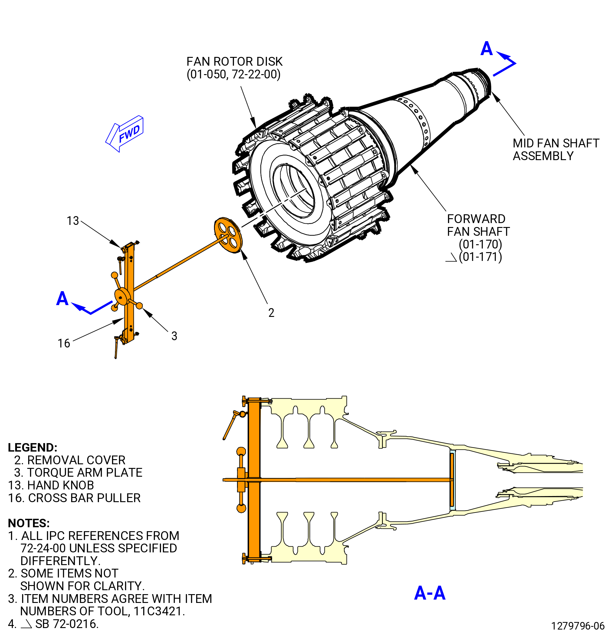
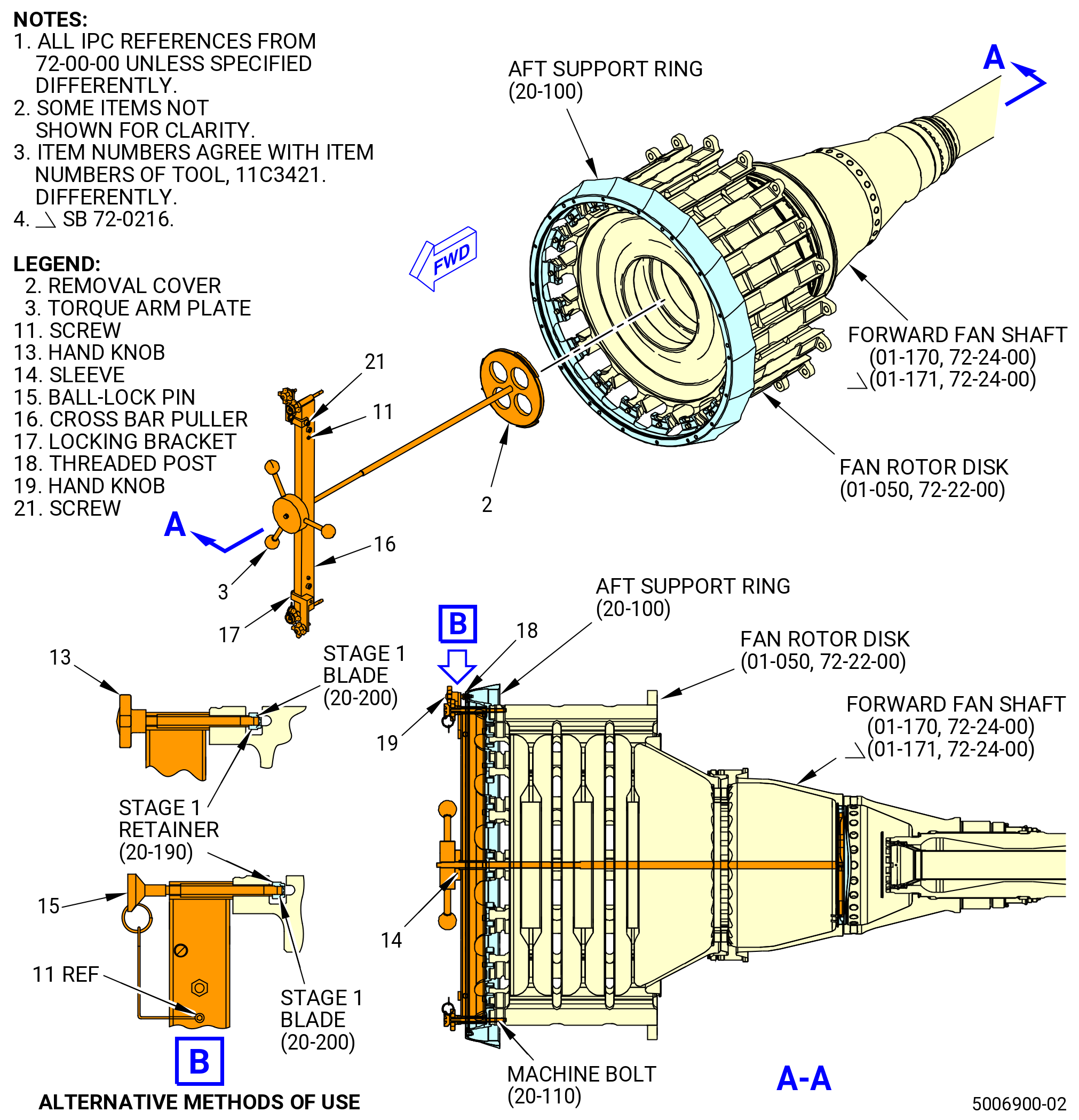
| (4) | Remove the forward fan shaft cover with the 11C3421 fan shaft cover removal tool as follows: |
| (a) | Attach the removal cover (item 2) to the forward fan shaft cover as follows: |
| 1 | Line the tabs on the removal cover (item 2) with the open slots on the forward fan shaft cover. |
| 2 | Turn the removal cover (item 2) CW to engage the three tabs fully in the forward fan shaft cover. |
| (b) | Install the cross bar puller (item 16) on the forward end of the removal cover (item 2). |
| (c) | Attach the cross bar puller (item 16) to the fan rotor disk (01-050 , 72-22-00) (SIN 830A0) nuts or aft support ring (20-100 , 72-00-00) (SIN 8300A) with the ball-lock pins (item 15) at two locations. Refer to Figure 321. |
| (d) | Attach the cross bar puller (item 16) to the fan rotor disk nuts with the hand knobs (item 13) at two locations. Tighten the hand knobs (item 13). |
| (e) | Install the sleeve (item 14) and the torque arm plate (item 3) on the shaft of the removal cover (item 2). |
| (f) | Make sure the removal cover (item 2) is engaged to the forward fan shaft cover. Turn the handles on the torque arm plate (item 3) to disengage the forward fan shaft cover from the forward fan shaft. |
| NOTE: |
|
| (g) | Remove the torque arm plate (item 3) and the sleeve (item 14). |
| (h) | Remove the cross bar puller (item 16) from the fan rotor disk or aft support ring (20-100 , 72-00-00) (SIN 8300A). |
| (i) | Remove the 11C3421 fan shaft cover removal tool and the forward fan shaft cover from the forward fan shaft. |
| (j) | Remove the forward fan shaft cover from the removal cover (item 2). |
| (k) | Remove and discard the packing (20-300 , 72-00-02) (SIN 81050) from the forward fan shaft cover. |
| * * * FOR ALL |
| Subtask 72-00-04-020-039 |
| * * * FOR ALL |
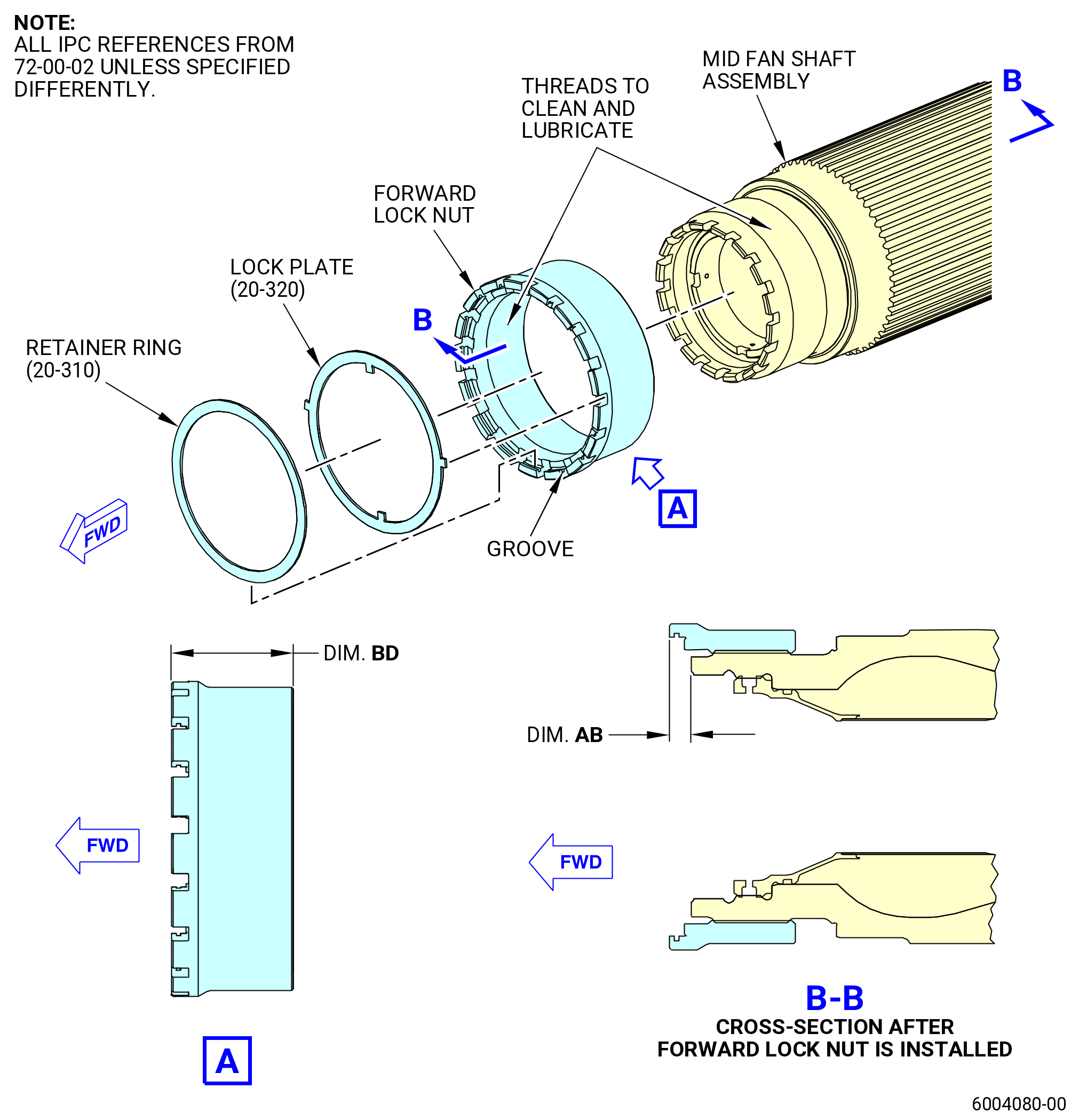
| I. | Alternative Procedure Available. Use this procedure when the fan booster assembly (20-010 , 72-00-02) (SIN 80000) or (20-011 , 72-00-02) (SIN 80000) is installed to the fan hub module (25-010 , 72-00-02) (SIN 00102) or (25-011 , 72-00-02) (SIN 00102) or (25-012 , 72-00-02) (SIN 00102). Remove the forward lock nut from the mid fan shaft assembly as follows: |
| (1) | Remove the retainer ring (20-310 , 72-00-02) (SIN 83091) and the lock nut plate (keyed ring) (20-320 , 72-00-02) (SIN 83092) from the forward lock nut. |
| (2) | Install the 11C3084 fan disk protector into the bore of the fan rotor disk and the forward fan shaft (01-170 , 72-24-00) (SIN 81002) or (01-171 , 72-24-00) (SIN 81002). Refer to Figure 322. |
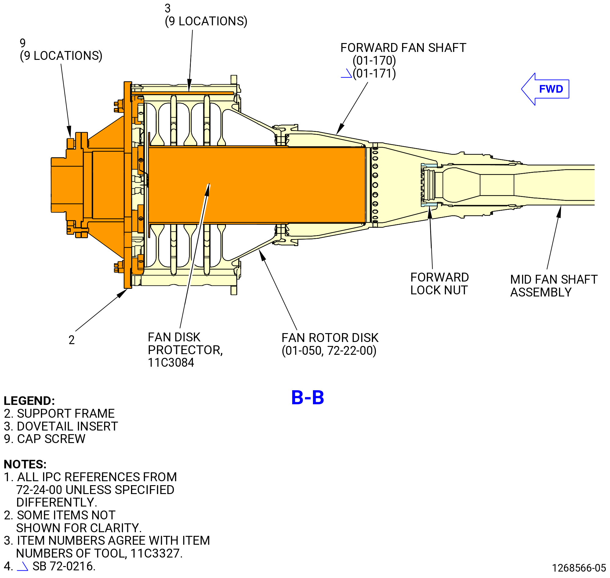
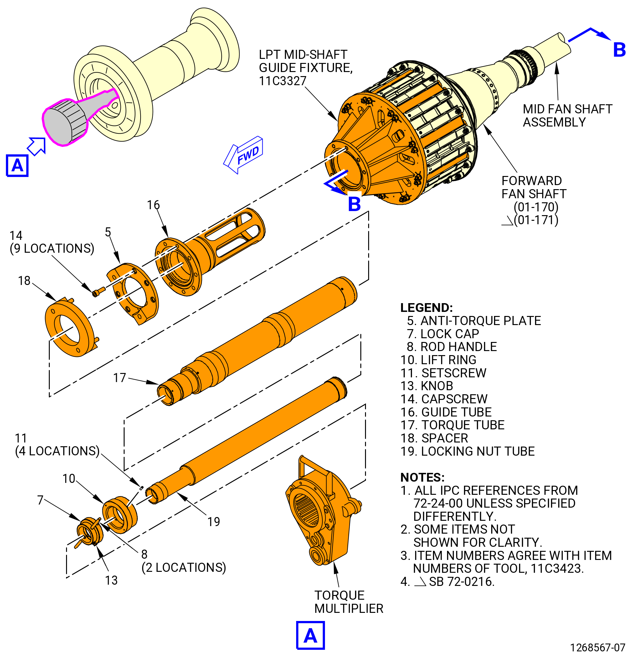
| (3) | Prepare to install the 11C3327 LPT mid-shaft guide fixture on the fan rotor disk (830A0) as follows: |
| (a) | Put the nine dovetail inserts (item 3) on a table. Make sure that the 18 rod feet (item 4) and (item 7) are turned to the install position. |
| (b) | Carefully install the nine dovetail inserts (item 3) into the dovetail slots of the fan rotor disk. |
| (c) | Turn the 18 rod feet (item 4) and (item 7) to the locked position. |
| WARNING: |
|
| (d) | Lift and install the support frame (item 2) on the fan rotor disk. |
| (e) | Attach the support frame (item 2) to the fan rotor disk with the nuts (item 13). |
| (f) | Tighten the nuts (item 13). |
| (g) | Make sure that the rod feet are in the locked position until the nuts are tight. |
| Subtask 72-00-04-020-040 |
| * * * FOR ALL |
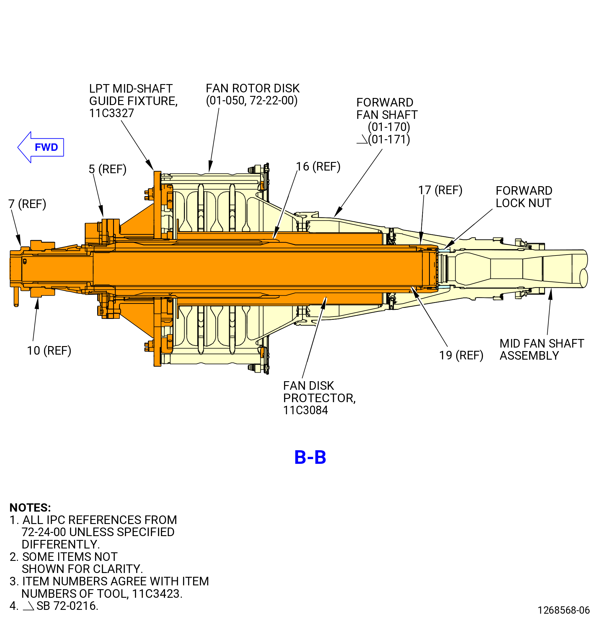
| (4) | Install the 11C3423 coupling nut torque fixture as follows. Refer to Figure 323. |
| (a) | Put the guide tube (item 16) into the 11C3327 LPT mid-shaft guide fixture and attach it with the capscrews (item 14) of the 11C3423 coupling nut torque fixture at the 2:30 o'clock and 9:30 o'clock positions. |
| (b) | Put the anti-torque plate (item 5) on the guide tube (item 16) and the capscrews at the 2:30 o'clock and 9:30 o'clock positions. |
| (c) | Attach the anti-torque plate (item 5) with the capscrews (item 14) at seven locations. |
| (d) | Put the torque tube (item 17) and the locking nut tube (item 19) in a horizontal position. |
| (e) | Install the lift ring (item 10) on the torque tube (item 17) and tighten the setscrews (item 11) into the slot of the torque tube. |
| WARNING: |
|
| (f) | Lift the torque tube assemblies that includes (item 17), (item 19), (item 7), and (item 10). |
| CAUTION: |
|
| 1 | Use the cradle adapter (item 6) of the 9429M59 breach loader to lift the torque tube assemblies. Refer to Subtask 72-00-04-020-045 (paragraph 3.C.(1)) to install the cradle adapter (item 6). |
| (g) | Insert the torque tube assemblies into the anti-torque plate (item 5) and push aft. Refer to Figure 323. |
| (h) | Remove the lifting device. |
| (i) | Install the lock cap (item 7) with the rod handle (item 8) at two locations attached. |
| (j) | Make sure that the knob (item 13) is in the locked position in the locking nut tube (item 19). |
| Subtask 72-00-04-020-041 |
| * * * FOR ALL |
| (k) | Make sure that the torque tube (item 17) is in the unlocked position. |
| (l) | Make sure that the scribe lines on the torque tube (item 17) and the locking nut tube (item 19) are aligned. |
| (m) | Push the torque tube (item 17) of the 11C3423 coupling nut torque fixture and turn to engage it in the slots of the nut slots. Refer to Figure 323. |
| (n) | Hold the torque tube (item 17) and turn the locking nut tube (item 19) to the locked position. Make sure that the tube is locked axially. |
| (o) | Pull the torque tube to the forward end until the knob (item 13) engages in the torque tube (item 17). |
| (p) | Turn the knob (item 13) CCW and pull the lock cap forward to remove the lock cap (item 7). |
| (q) | Remove the lift ring (item 10) of the hydraulic torque multiplier. |
| (r) | Attach a hoist to the handle on the multiplier. Operate the hoist and lift the torque multiplier and align it with the torque tube (item 17) of the 11C3423 coupling nut torque fixture and engage the splines on the lift ring (item 10). |
| (s) | Turn the hydraulic torque multiplier slightly to locate the pins of the hydraulic torque multiplier with the forward end of the anti-torque plate (item 5). |
| (t) | Operate the hydraulic torque multiplier to loosen the forward lock nut one turn only. |
| (u) | Do not completely disengage the forward lock nut from the mid fan shaft assembly at this time. |
| (v) | Remove the hydraulic torque multiplier from the torque tube (item 17) of the 11C3423 coupling nut torque fixture and put it aside. |
| (w) | Install the lift ring (item 10) on the torque tube (item 17) and tighten the setscrews (item 11) into the slot of the torque tube. |
| (x) | Install the lock cap (item 7) on the locking tube (item 19) and torque tube (item 17). Make sure that the rod handles (item 8) are installed. |
| (y) | Make sure that the knob (item 13) locks into position into the one hole of the torque tube (item 17). The scribe marks on the locking ring and locking tube will line up into position. |
| (z) | Manually turn the torque tube (item 17) to remove the forward lock nut. |
| WARNING: |
|
| (aa) | Remove the torque tube assemblies that consists of (item 17), (item 19), (item 7), and (item 10). |
| CAUTION: |
|
| 1 | Use the cradle adapter (item 6) of the 9429M59 breach loader to remove the torque tube assemblies. Refer to Subtask 72-00-04-020-045 (paragraph 3.C.(1)) to install the cradle adapter (item 6). |
| Subtask 72-00-04-020-065 |
| * * * FOR ALL |
| * * * FOR |
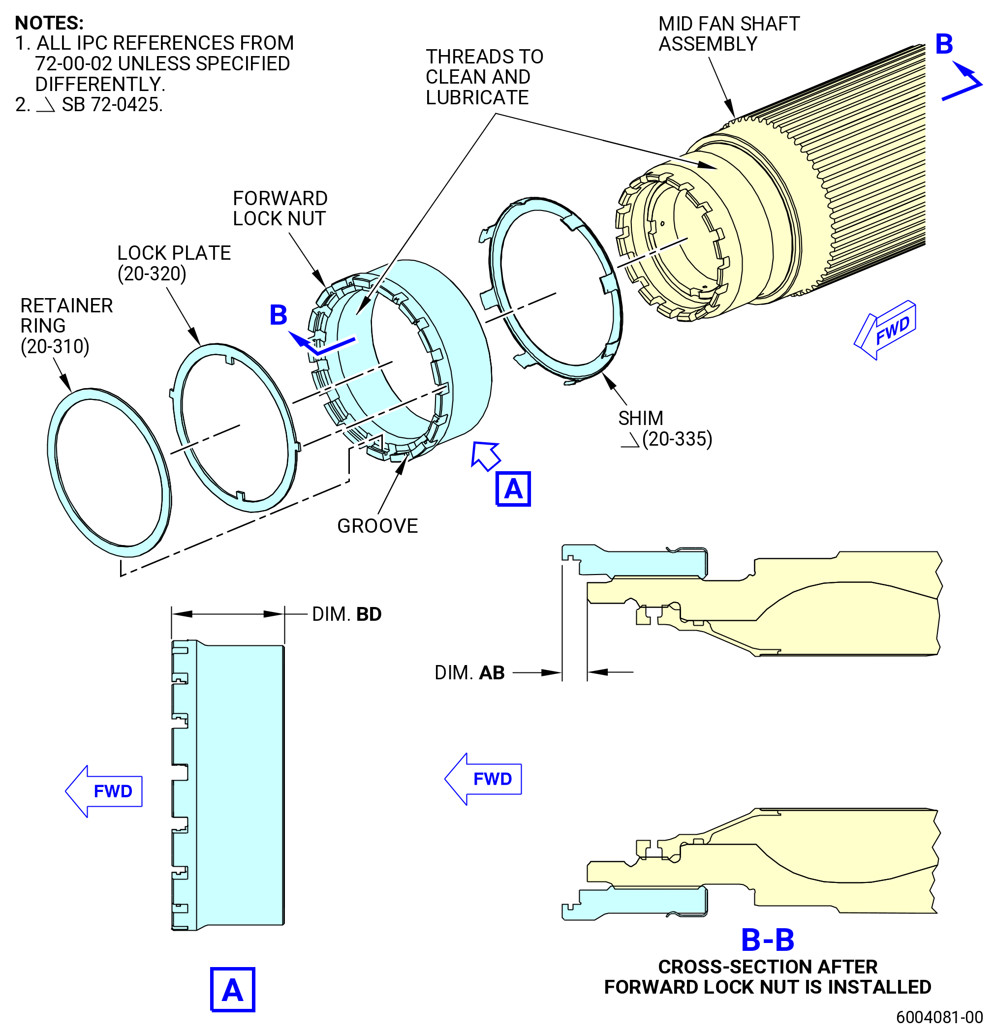
| * * * SB 72-0425( Engines with Spacer Shim on the Mid Fan Shaft Assembly ) |
| (ab) | Remove and discard the spacer shim (shim) (20-335 , 72-00-02) (SIN 81072) from the mid fan shaft assembly. Refer to Figure 324. |
| NOTE: |
|
| * * * FOR |
| * * * END SB 72-0425 |
| Subtask 72-00-04-020-066 |
| * * * FOR ALL |
| (ac) | Remove the forward locking nut from the forward fan shaft (01-170 , 72-24-00) (SIN 81002) or (01-171 , 72-24-00) (SIN 81002). Refer to Figure 323. |
| Subtask 72-00-04-020-057 |
| * * * FOR ALL |
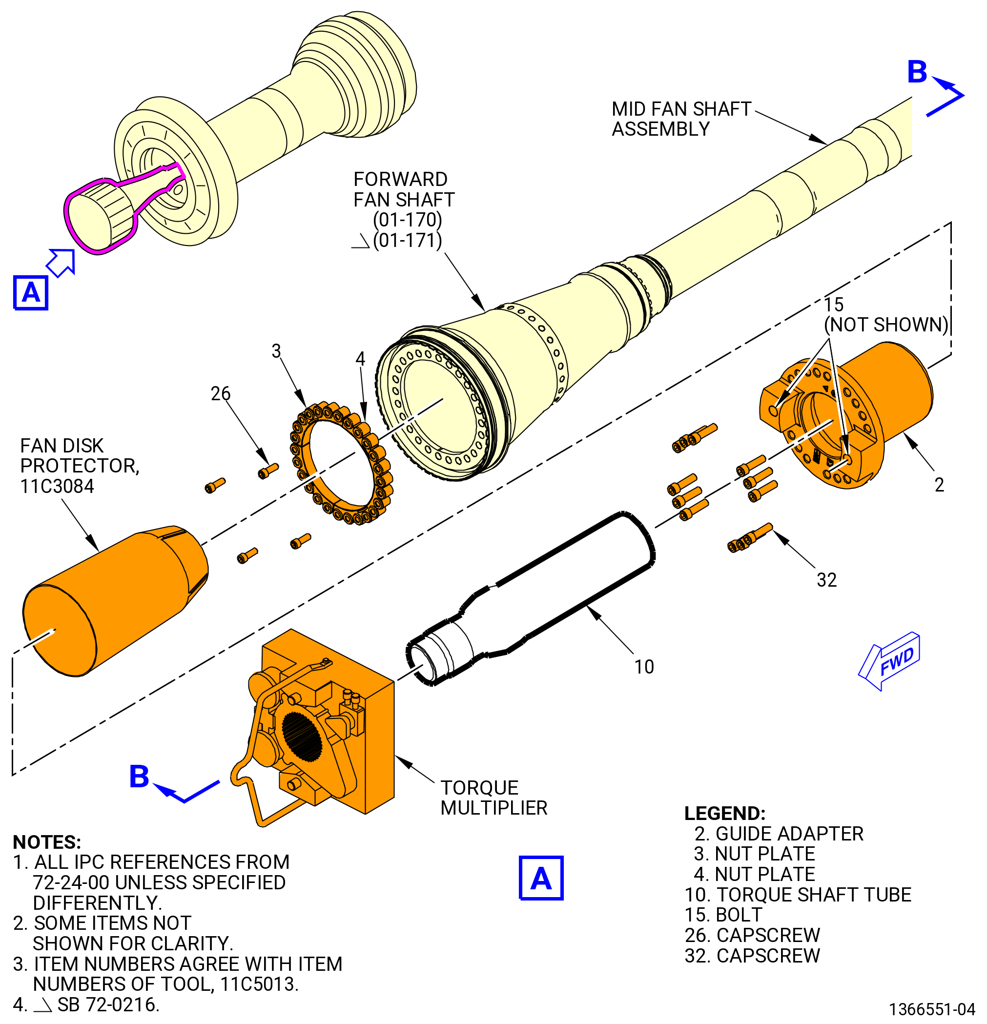
| I.A. | Alternative Procedure. Use this procedure when the fan booster assembly (20-010 , 72-00-02) (SIN 80000) or (20-011 , 72-00-02) (SIN 80000) was previously removed from the fan hub module (25-010 , 72-00-02) (SIN 00102) or (25-011 , 72-00-02) (SIN 00102) or (25-012 , 72-00-02) (SIN 00102). Remove the forward lock nut from the mid fan shaft assembly. Refer to Figure 320, Figure 325, and do as follows: |
| (1) | Remove the retainer ring (20-310 , 72-00-02) (SIN 83091) and the keyed ring (20-320 , 72-00-02) (SIN 83092) from the forward lock nut. |
| (2) | Install the 11C5013 install/remove fixture and coupling nut wrench (item 10) as follows: |
| (a) | Install the two nut plates (item 3) and the two nut plates (item 4) of the 11C5013 install/remove fixture to the aft side of the forward fan shaft (01-170 , 72-24-00) (SIN 81002) or (01-171 , 72-24-00) (SIN 81002) forward flange with four 5/8 inch capscrews (item 26). Torque capscrew (item 26) to 100 ft lb (140 Nm). |
| NOTE: |
|
| (b) | Install the protector (item 8) of the 11C3084 fan disk protector in the bore of the forward fan shaft (01-170 , 72-24-00) (SIN 81002) or (01-171 , 72-24-00) (SIN 81002). |
| WARNING: |
|
| (c) | Use a hoist and applicable nylon strap to install the guide adapter (item 2) of the 11C5013 install/remove fixture on the forward side of the forward fan shaft forward flange with 18 3/4 inch capscrews (item 32). |
| (d) | Torque the capscrews (item 32) to 100 ft lb. (140 Nm). |
| (e) | Use a lifting assistance and a two-legged sling for each tool TDS. Install the coupling nut wrench (item 10). |
| (f) | Make sure that the castellations of the coupling nut wrench (item 10) engage with the forward lock nut castellations. |
| (g) | Unthread the lock bolts (item 15) without removing them from the adapter (item 2). |
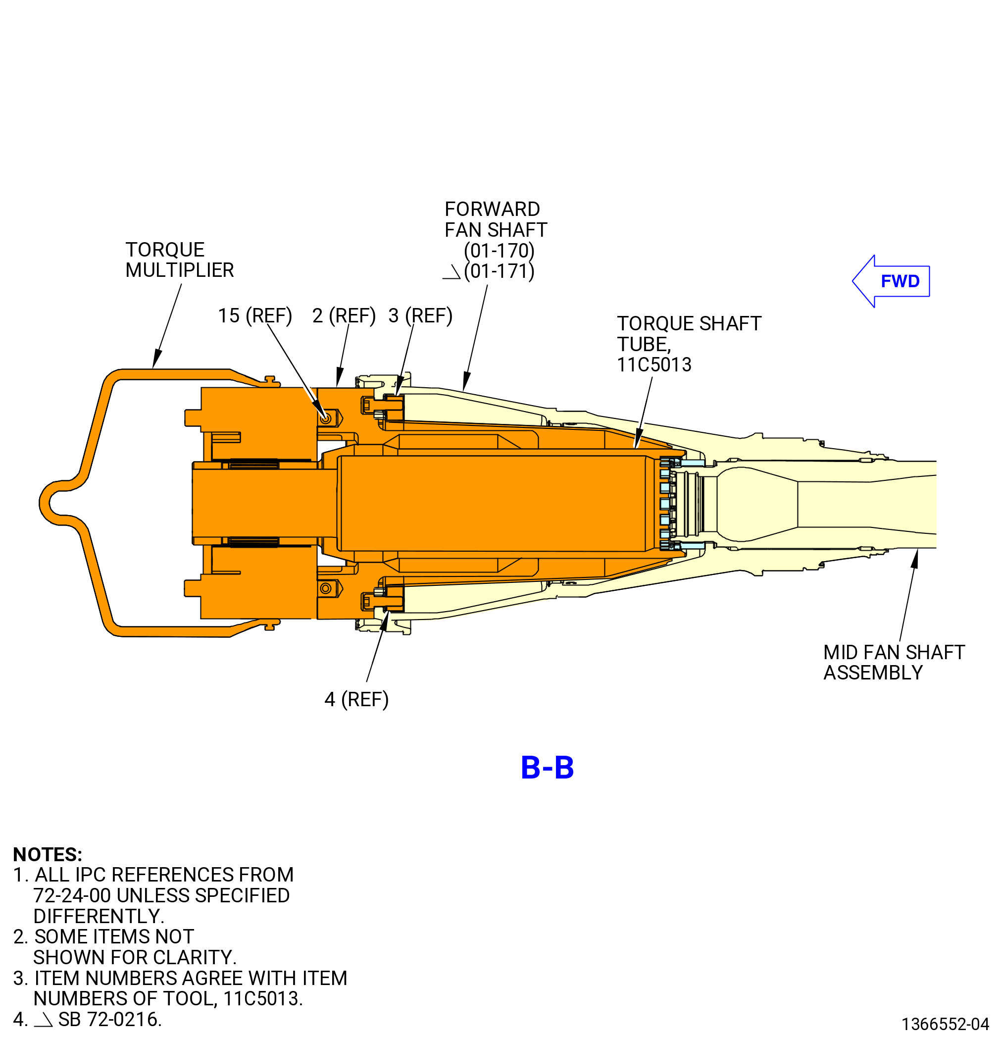
| (3) | Install the torque multiplier at the forward end of the coupling nut wrench as follows: |
| (a) | Use a lifting assistance to align the torque multiplier with the coupling nut wrench (item 10). |
| (b) | Align and insert the reaction pins of the torque multiplier in the holes of the adapter (item 2). |
| (c) | Attach firmly the reaction pins by tightening the lock bolts (item 15) until solidly contact the torque multiplier reaction pins. |
| (4) | Loosen the forward lock nut with the torque multiplier, for not more than four turns. |
| (5) | Remove the torque multiplier. |
| (6) | Remove the coupling nut wrench (item 10) use the lifting assistance and two-legged sling for each TDS. |
| (7) | Use a hoist and applicable nylon strap to remove the guide adapter (item 2) of the 11C5013 install/remove fixture. |
| (8) | Remove the forward lock nut from the forward fan shaft (01-170 , 72-24-00) (SIN 81002) or (01-171 , 72-24-00) (SIN 81002). |
| (9) | Remove two nut plates (item 3) and two nut plates (item 3) of the 11C5013 install/remove fixture from the aft-side of the forward fan shaft (01-170 , 72-24-00) (SIN 81002) or (01-171 , 72-24-00) (SIN 81002) forward flange. |
| * * * FOR ALL |
|
|
| Subtask 72-00-04-020-011 |
| * * * FOR ALL |
| CAUTION: |
|
| J. | Remove the flange nuts, spacers, brackets, and lockplates from the appropriate turbine center frame assembly (TCF) listed below and LPT module assembly flange. Refer to Figure 326 and do as follows: |
| • |
|
| • |
|
| • |
|
| • |
|
| • |
|
| (1) | Loosen and remove the self-locking nuts (93541) at 150 locations from the LPT studs at the TCF-LPT flange. |
| (2) | At the bolthole locations that have a bracket, remove the bracket. |
| (3) | At the boltholes that do not have a bracket, remove the spacers. |
| (4) | Remove the lockplates at 75 locations that are attached over every pair of the SPL free-running studs (LPT studs) (35-020 , 72-00-02) (SIN 93520). |
| (5) | Remove the LPT studs with your fingers. |
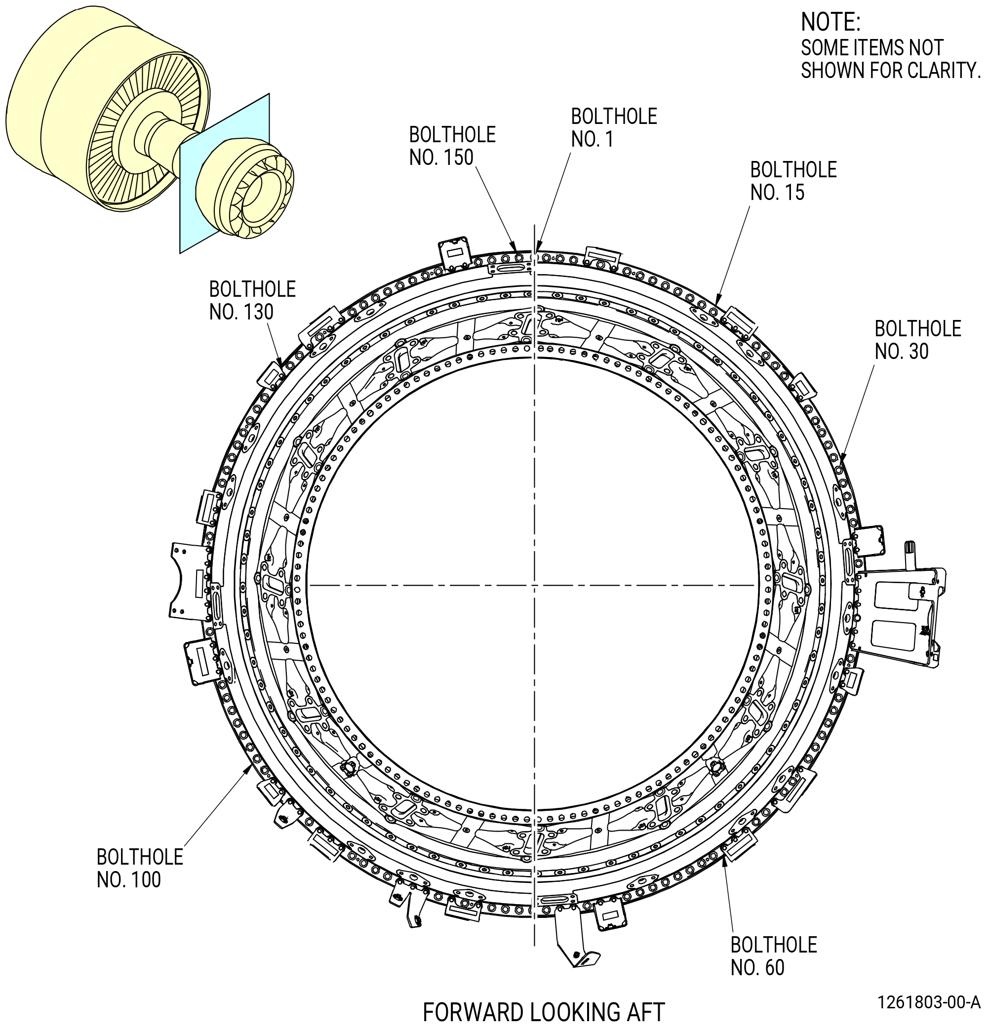
| (6) | Make sure that the boltholes are numbered in increments of ten from the top vertical centerline (TVCL), ALF. |
| (7) | Install the guide pins (item 6) of the 9446M40 LPT alignment fixture at stud hole locations No. 25, 60, 95, and 134 on the TCF and the LPT module assembly flange. Refer to Figure 327. |
| * * * FOR ALL |
| Subtask 72-00-04-020-010 |
| * * * FOR ALL |
| K. | Alternative Procedure Available. Install the 11C5003 push/pull fixture on the mid fan shaft assembly in the fan rotor disk (01-050 , 72-22-00) (SIN 830A0) and do as follows: |
| (1) | Remove the capscrews (item 14) of the 11C3423 coupling nut torque fixture from the anti-torque plate (item 5), and remove the anti-torque plate. Refer to Figure 323. |
| (2) | Remove the capscrews (item 14) at the 2:30 o'clock and 9:30 o'clock positions. |
| (3) | Remove the guide tube (item 16) from the 11C3327 LPT mid-shaft guide fixture. |
| WARNING: |
|
| CAUTION: |
|
| (4) | Lift the 11C5003 push/pull fixture with the nylon tube (item 3) of the 9429M59 breach loader. Refer to Subtask 72-00-04-020-045 (paragraph 3.C.(1)) to install the nylon tube (item 3). |
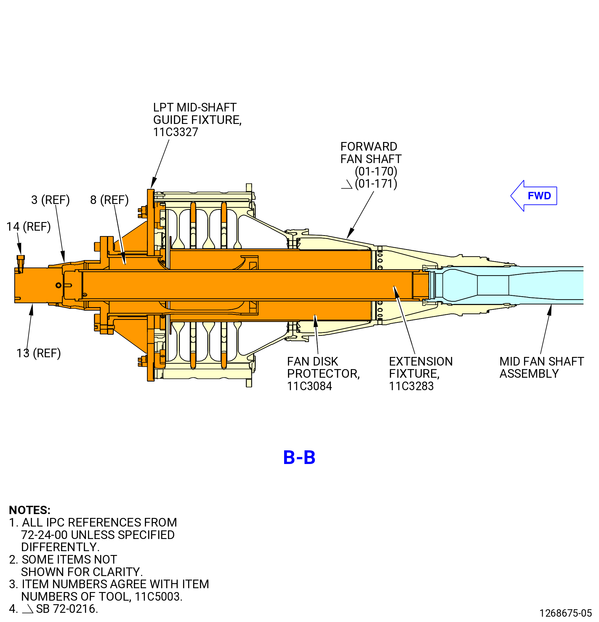
| (5) | Install the 11C5003 push/pull fixture into the forward fan shaft (01-170 , 72-24-00) (SIN 81002) or (01-171 , 72-24-00) (SIN 81002). Refer to Figure 328 and do as follows: |
| WARNING: |
|
| (a) | Lift and install the adapter guide (item 8) into the fan rotor disk and attach with the capscrews (item 14) of the 11C3423 coupling nut torque fixture to the 11C3327 LPT mid-shaft guide fixture at nine locations. |
| (b) | Add hoist and straps to lift the 11C3283 extension fixture into the adapter guide (item 8) and thread the extension tube (item 2) of the 11C3283 extension fixture on the forward end of the mid fan shaft assembly. |
| (c) | Remove the capscrew (item 4) of the 11C3283 extension fixture and then the guide tip (item 3) from the extension tube (item 2) of the 11C3283 extension fixture. |
| (d) | Screw the 30 ton adapter (item 3) on the adapter guide (item 8). |
| (e) | Attach the 30 ton single acting cylinder (item 13) to the 30 ton adapter (item 3) with the setscrew (item 19). The cylinder should be in the retracted position. |
| (f) | Make sure that the adapter guide (item 8) is fully on the 11C3327 LPT mid-shaft guide fixture. |
| (6) | Adjust the CG to approximately 9.5 inches on the CG bar scale of the 9C1147 VCG lift fixture. Refer to Figure 317. |
| (7) | Install the Hydra-Set Scale to the LPT module assembly as follows: |
| (a) | Attach the Hydra-set Scale to an overhead crane hook. |
| (b) | Set the Hydra-Set Scale to 5100 lb (2313 kg) before it is attached to the 9C1147 VCG lift fixture. |
| (c) | Attach the Hydra-Set Scale to the lift eye (item 13) of the 9C1147 VCG lift fixture. |
| (8) | Remove the 9429M47 LPT support overhead adapter from the LPT module assembly. Refer to Figure 302. |
| Subtask 72-00-04-020-051 |
| * * * FOR ALL |
| K.A. | Alternative Procedure. Install the 11C5003 push/pull fixture on the mid fan shaft assembly and forward fan shaft (01-170 , 72-24-00) (SIN 81002) or (01-171 , 72-24-00) (SIN 81002) and do as follows: |
| (1) | Remove the capscrews (item 14) of the 11C3423 coupling nut torque fixture and the anti-torque plate (item 5) from the 11C4368 LPT mid-shaft guide fixture. Refer to Figure 323. |
| WARNING: |
|
| (2) | Lift and remove the guide tube (item 16) from the 11C4368 LPT mid-shaft guide fixture with the nylon tube (item 3) of the 9429M59 breach loader. |
| (3) | Lift and remove the adapter guide (item 8) of the 11C5003 push/pull fixture with the nylon tube (item 3) of the 9429M59 breach loader. |
| (4) | Install the 11C5003 push/pull fixture into the forward fan shaft. Refer to Figure 328 and do as follows: |
| WARNING: |
|
| (a) | Lift and install the adapter guide (item 8) into the fan rotor disk and attach with the capscrews (item 14) of the 11C3423 coupling nut torque fixture at nine locations. Refer to Figure 323. |
| (b) | Attach hoist straps to the extension tube (item 2) of the 11C3283 extension fixture and lift it to install it into the adapter guide (item 8) of the 11C5003 push/pull fixture. Install the extension tube onto the forward end of the mid fan shaft assembly. Refer to Figure 328. |
| (c) | Remove the capscrew (item 4) of the 11C3283 extension fixture and the guide tip (item 3) from the extension tube (item 2). |
| (d) | Install the 30 ton cylinder adapter (item 3) of the 11C5003 push/pull fixture onto the adapter guide (item 8). |
| (e) | Attach the 30 ton single acting cylinder (item 13) to the 30 ton cylinder adapter (item 3) with the setscrew (item 19). The 30 ton cylinder adapter should be in the retracted position. |
| (f) | Make sure the adapter guide (item 8) is fully on the 11C4368 LPT mid-shaft guide fixture. |
| (5) | Install the Hydra-Set Scale to the LPT module assembly as follows: |
| (a) | Attach the Hydra-Set Scale to an overhead crane hook. |
| (b) | Set the Hydra-Set Scale to 4025 lb (1826 kg) before it is attached to the 9429M77 lift and turn fixture. |
| (c) | Attach the 9429M77 lift and turn fixture to the Hydra-Set scale. |
| (d) | Attach two assembly hoists (item 24) of the 9429M77 lift and turn fixture with the turnbuckle to the lift arms (item 19) and (item 20) aft pivot trunnions of the 11C4266 CG lift fixture. |
| (e) | Attach two assembly hoists (item 24) of the 9429M77 lift and turn fixture with the turnbuckle to the lift arms (item 19) and (item 20) forward pivot trunnions of the 11C4266 CG lift fixture. |
| (f) | Use turnbuckle to initially adjust the CG of the LPT module. |
| (6) | Remove the 9429M47 LPT support overhead adapter from the TRF bootstrap bracket (01-160) (SIN 941E1) on the LPT module assembly. Refer to Figure 302. |
| (7) | Remove the 9429M47 LPT support overhead adapter from the overhead hanger assembly. |
| Subtask 72-00-04-020-067 |
| * * * FOR ALL |
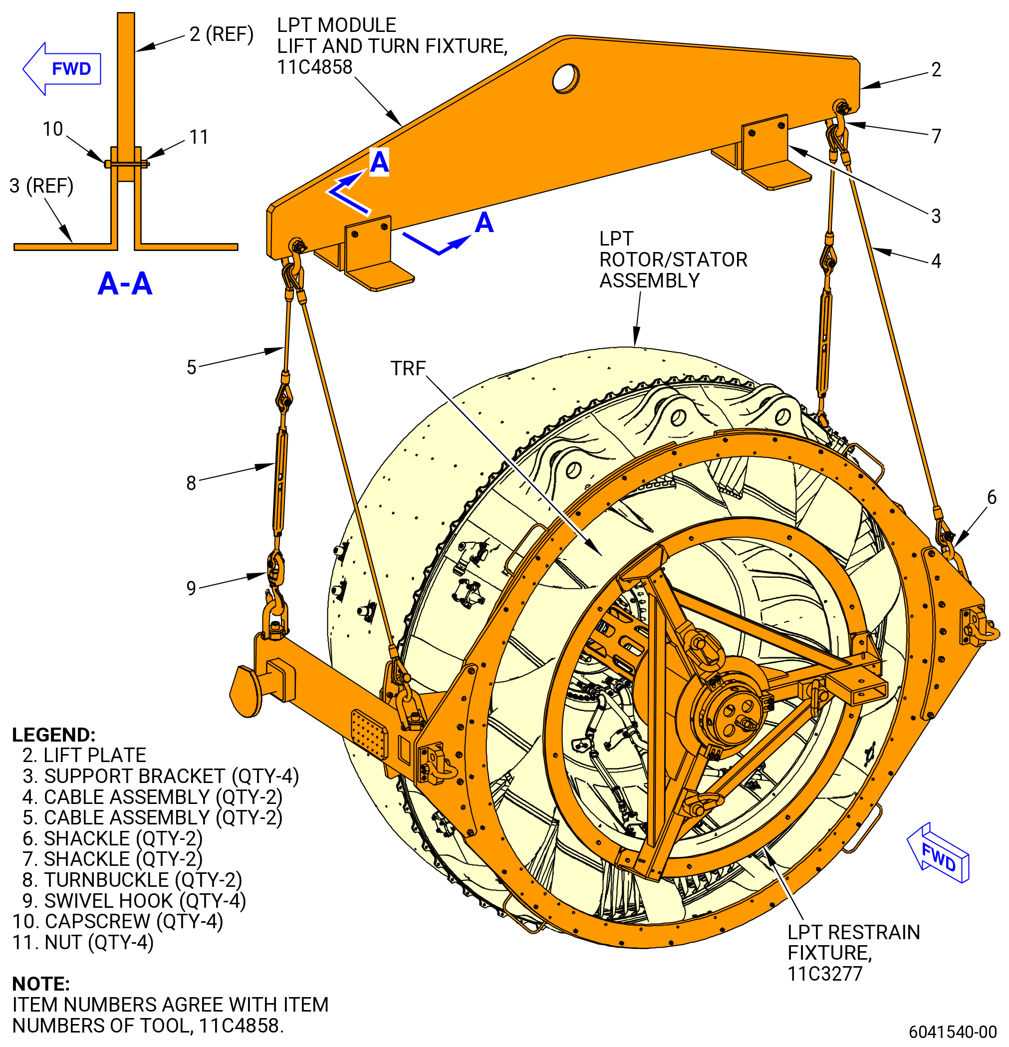
| K.B. | Alternative Procedure. Install the 11C3278 push/pull fixture on the mid fan shaft assembly and forward fan shaft (01-170 , 72-24-00) (SIN 81002) or (01-171 , 72-24-00) (SIN 81002) and do as follows: |
| (1) | Remove the capscrews (item 14) of the 11C3423 coupling nut torque fixture and the anti-torque plate (item 5) from the 11C4368 LPT mid-shaft guide fixture. Refer to Figure 323. |
| WARNING: |
|
| (2) | Lift and remove the guide tube (item 16) from the 11C4368 LPT mid-shaft guide fixture with the nylon tube (item 3) of the 9429M59 breach loader. |
| (3) | Lift and remove the adapter guide (item 8) of the 11C3278 push/pull fixture with the nylon tube (item 3) of the 9429M59 breach loader. |
| (4) | Install the 11C3278 push/pull fixture into the forward fan shaft. Refer to Figure 328 and do as follows: |
| WARNING: |
|
| (a) | Lift and install the adapter guide (item 8) into the fan rotor disk and attach with the capscrews (item 14) of the 11C3423 coupling nut torque fixture at nine locations. Refer to Figure 323. |
| (b) | Attach the hoist straps to the extension tube (item 2) of the 11C3283 extension fixture and lift it to install it into the adapter guide (item 8) of the 11C3278 push/pull fixture. Install the extension tube onto the forward end of the mid fan shaft assembly. Refer to Figure 328. |
| (c) | Remove the capscrew (item 4) of the 11C3283 extension fixture and the guide tip (item 3) from the extension tube (item 2). |
| (d) | Install the 30 ton cylinder adapter (item 3) of the 11C3278 push/pull fixture onto the adapter guide (item 8). |
| (e) | Attach the 30 ton single acting cylinder (item 13) to the 30 ton cylinder adapter (item 3) with the setscrew (item 19). The 30 ton cylinder adapter should be in the retracted position. |
| (f) | Make sure the adapter guide (item 8) is fully on the 11C4368 LPT mid-shaft guide fixture. |
| (5) | Install the hydra-set scale to the LPT module assembly as follows: |
| (a) | Attach the hydra-set scale to an overhead crane hook. |
| (b) | Set the hydra-set scale to 4025 lb (1826 kg) before it is attached to the 11C4858 lift. |
| (c) | Attach the lift plate (item 2) of the 11C4858 lift and turn fixture to the hydra-set scale. |
| (d) | Prepare two long sling assemblies by assembling a shackle (item 6) and swivel hook (item 9) to the long sling (item 4). |
| (e) | Adjust the length of both turnbuckles (item 8) to 20 inches (508 mm) between the bolt pin centers. |
| (f) | Prepare two short sling assemblies by assembling a shackle (item 6) and swivel hook (item 9) to one end of the turnbuckle (item 8) and the short sling (item 5) to the opposite end. |
| (g) | Connect one each of the short and long sling assemblies to the lift plate (item 2) with shackle (item 7) on each side. |
| (h) | Attach each short sling assembly swivel hook (item 9) to the pivot trunnions located on the forward side of the 11C4266 CG lift fixture. |
| (i) | Attach each long sling assembly swivel hook (item 9) to the pivot trunnions located on the aft side of the 11C4266 CG lift fixture. |
| (j) | If necessary, use the turnbuckles to initially adjust the CG lift fixture of the LPT module assembly. |
| (6) | Remove the 9429M47 LPT support overhead adapter from the TRF bootstrap bracket (01-160) (SIN 941E1) on the LPT module assembly. Refer to Figure 302. |
| (7) | Remove the 9429M47 LPT support overhead adapter from the overhead hanger assembly. |
| Subtask 72-00-04-020-058 |
| * * * FOR ALL |
| K.C. | Alternative Procedure. Use this procedure when the fan booster assembly (20-010 , 72-00-02) (SIN 80000) or (20-011 , 72-00-02) (SIN 80000) is removed previously from the fan hub module (25-010 , 72-00-02) (SIN 00102) or (25-011 , 72-00-02) (SIN 00102) or (25-012 , 72-00-02) (SIN 00102). Install the 11C5013 install/remove fixture on the mid fan shaft assembly and the forward fan shaft (01-170 , 72-24-00) (SIN 81002) or (01-171 , 72-24-00) (SIN 81002). Refer to Figure 329 and do as follows: |
| (1) | Install the 11C5013 install/remove fixture as follows: |
| (a) | Install two nut plates (item 3) and two nut plates (item 4) of the 11C5013 install/remove fixture to the aft side of the forward fan shaft (01-170 , 72-24-00) (SIN 81002) or (01-171 , 72-24-00) (SIN 81002) forward flange with four 5/8 inch capscrews (item 18). Torque the capscrews to 100 ft lb (140 Nm). |
| NOTE: |
|
| (b) | Install the protector (item 8) of the 11C3084 fan disk protector in the bore of the forward fan shaft (01-170 , 72-24-00) (SIN 81002) or (01-171 , 72-24-00) (SIN 81002). |
| WARNING: |
|
| (c) | Use a hoist and applicable nylon strap to install the guide adapter (item 5) of the 11C5013 install/remove fixture on the forward side of the forward fan shaft forward flange with 22 capscrews (item 32). |
| (d) | Torque the capscrews (item 32) to 100 ft in. (140 Nm). |
| (e) | Install the 11C4272 extension fixture and remove the nylon guide tip. |
| WARNING: |
|
| (f) | Connect an overhead hoist to the hoist swivel ring (item 35) located around the 30 ton cylinder adapter (item 7). |
| NOTE: |
|
| WARNING: |
|
| (g) | Lift the assembly and align it horizontally with the mid fan shaft assembly. |
| (h) | Manually thread the 30 ton cylinder adapter (item 7) to the guide adapter (item 5). |
| NOTE: |
|
| (i) | Make sure that the 11C4272 extension fixture is fully locked and seated to the mid fan shaft assembly. |
| (j) | Make sure that the 30 ton cylinder adapter (item 7) assembly is fully engaged to the 11C4272 extension fixture. |
| Subtask 72-00-04-020-012 |
| * * * FOR ALL |
| L. | Alternative Procedure Available. Remove the LPT module assembly from the propulsor assembly as follows: |
| (1) | Attach a hydraulic pump to the coupler (item 14) on the 30 ton single acting cylinder (item 13) of the 11C5003 push/pull fixture. Refer to Figure 328. |
| (a) | Make sure that all the connections are tight. |
| WARNING: |
|
| CAUTION: |
|
| (2) | Use the hydraulic pump to pressurize the 30 ton single acting cylinder (item 13) of the 11C5003 push/pull fixture and push the extension tube (item 2) of the 11C3283 extension fixture to the aft end to remove the mid fan shaft assembly from the forward fan shaft (01-170 , 72-24-00) (SIN 81002) or (01-171 , 72-24-00) (SIN 81002) as follows: |
| NOTE: |
|
| NOTE: |
|
| (a) | After the mid fan shaft assembly disengages, reset the hydraulic pump to bleed-off the pressure and use the hydraulic pressure to push the mid fan shaft assembly and the LPT module assembly aft until you have a 1.0 inch (25 mm) space between the LPT and the TCF flange. |
| NOTE: |
|
| (3) | If necessary, adjust the CG on the 9C1147 VCG lift fixture as follows. Refer to Figure 317. |
| (a) | Make sure that the gap between the LPT and the TCF flange remains the same around the circumference. |
| (b) | Make sure that the guide pins do not bind with the TCF flange. |
| NOTE: |
|
| Subtask 72-00-04-020-052 |
| * * * FOR ALL |
| L.A. | Alternative Procedure. Pull the LPT module assembly aft from the propulsor assembly as follows: |
| (1) | Attach a hydraulic hand pump to the coupler (item 14) on the 30 ton single acting cylinder (item 13) of the 11C5003 push/pull fixture. Refer to Figure 328. |
| (a) | Check all connections for tightness. |
| WARNING: |
|
| CAUTION: |
|
| (2) | Use the hydraulic hand pump to pressurize the 30 ton single acting cylinder (item 13) of the 11C5003 push/pull fixture and push the 11C3283 extension fixture tube to the aft end to remove the mid fan shaft assembly from the forward fan shaft (01-170 , 72-24-00) (SIN 81002) or (01-171 , 72-24-00) (SIN 81002). |
| NOTE: |
|
| NOTE: |
|
| (a) | After the mid fan shaft assembly disengages, reset the hydraulic pump to bleed-off the pressure and use the hydraulic pressure to push the mid fan shaft assembly and the LPT module assembly aft until there is a 1.0 inch (25 mm) space between the LPT and the TCF flange. |
| (3) | Adjust the CG on the 9429M77 lift and turn fixture as necessary. Use the turnbuckle located on the assembly hoist (item 24) to adjust the CG. Refer to Figure 319. |
| (a) | Make sure the gap between the LPT module assembly and TCF flange remains even around the circumference. |
| (b) | Make sure the guide pins (item 6) of the 9446M40 LPT alignment fixture do not get stuck in the TCF flange. Refer to Figure 327. |
| Subtask 72-00-04-020-068 |
| * * * FOR ALL |
| L.B. | Alternative Procedure. Pull the LPT module assembly aft from the propulsor assembly and do as follows: |
| (1) | Attach a hydraulic hand pump to the coupler (item 14) on the 30 ton single acting cylinder (item 13) of the 11C3278 push/pull fixture. Refer to Figure 328. |
| (a) | Do a check all connections for tightness. |
| WARNING: |
|
| CAUTION: |
|
| (2) | Use the hydraulic hand pump to pressurize the 30 ton single acting cylinder (item 13) of the 11C3278 push/pull fixture and push the 11C3283 extension fixture tube to the aft end to remove the mid fan shaft assembly from the forward fan shaft (01-170 , 72-24-00) (SIN 81002) or (01-171 , 72-24-00) (SIN 81002). |
| NOTE: |
|
| NOTE: |
|
| (a) | After the mid fan shaft assembly disengages, reset the hydraulic pump to bleed-off the pressure and use the hydraulic pressure to push the mid fan shaft assembly and the LPT module assembly aft until there is a 1.0 inch (25 mm) space between the LPT and the TCF flange. |
| (3) | Adjust the CG on the 11C4858 lift and turn fixture as necessary. Use the turnbuckle located on the assembly hoist (item 8) to adjust the CG. Refer to Figure 319. |
| (a) | Make sure the gap between the LPT module assembly and TCF flange remains even around the circumference. |
| (b) | Make sure the guide pins (item 6) of the 9446M40 LPT alignment fixture do not get stuck in the TCF flange. Refer to Figure 327. |
| Subtask 72-00-04-020-059 |
| * * * FOR ALL |
| L.C. | Alternative Procedure. Pull the LPT module assembly aft from the propulsor assembly as follows: |
| (1) | Attach a hydraulic hand pump to the 30 ton single acting cylinder (item 17) of the 11C5013 install/remove fixture. Refer to Figure 329. |
| NOTE: |
|
| (a) | Check all connections for tightness. |
| WARNING: |
|
| CAUTION: |
|
| (2) | Use the hydraulic hand pump to pressurize the 30 ton single acting cylinder (item 17) of the 11C5013 push/pull fixture and push the 11C4272 extension fixture to the aft end to remove the mid fan shaft assembly from the forward fan shaft (01-170 , 72-24-00) (SIN 81002) or (01-171 , 72-24-00) (SIN 81002). |
| NOTE: |
|
| NOTE: |
|
| (a) | After the mid fan shaft assembly disengages, reset the hydraulic pump to bleed-off the pressure and use the hydraulic pressure to push the mid fan shaft assembly and the LPT module assembly aft until there is a 1.0 inch (25 mm) space between the LPT and the TCF flange. |
| (3) | Adjust the CG on the 9429M77 lift and turn fixture as necessary. Use the turnbuckle located on the assembly hoist (item 24) to adjust the CG. Refer to Figure 319. |
| (a) | Make sure the space between the LPT module assembly and TCF flange stays even around the circumference. |
| (b) | Make sure the guide pins (item 6) of the 9446M40 LPT alignment fixture do not get stuck in the TCF flange. Refer to Figure 327. |
| (4) | Disconnect the hydraulic connections. |
| (5) | Disconnect and remove the 30 ton cylinder adapter (item 7) from the guide adapter (item 5) of the 11C5013 install/remove fixture. |
| Subtask 72-00-04-020-043 |
| * * * FOR ALL |
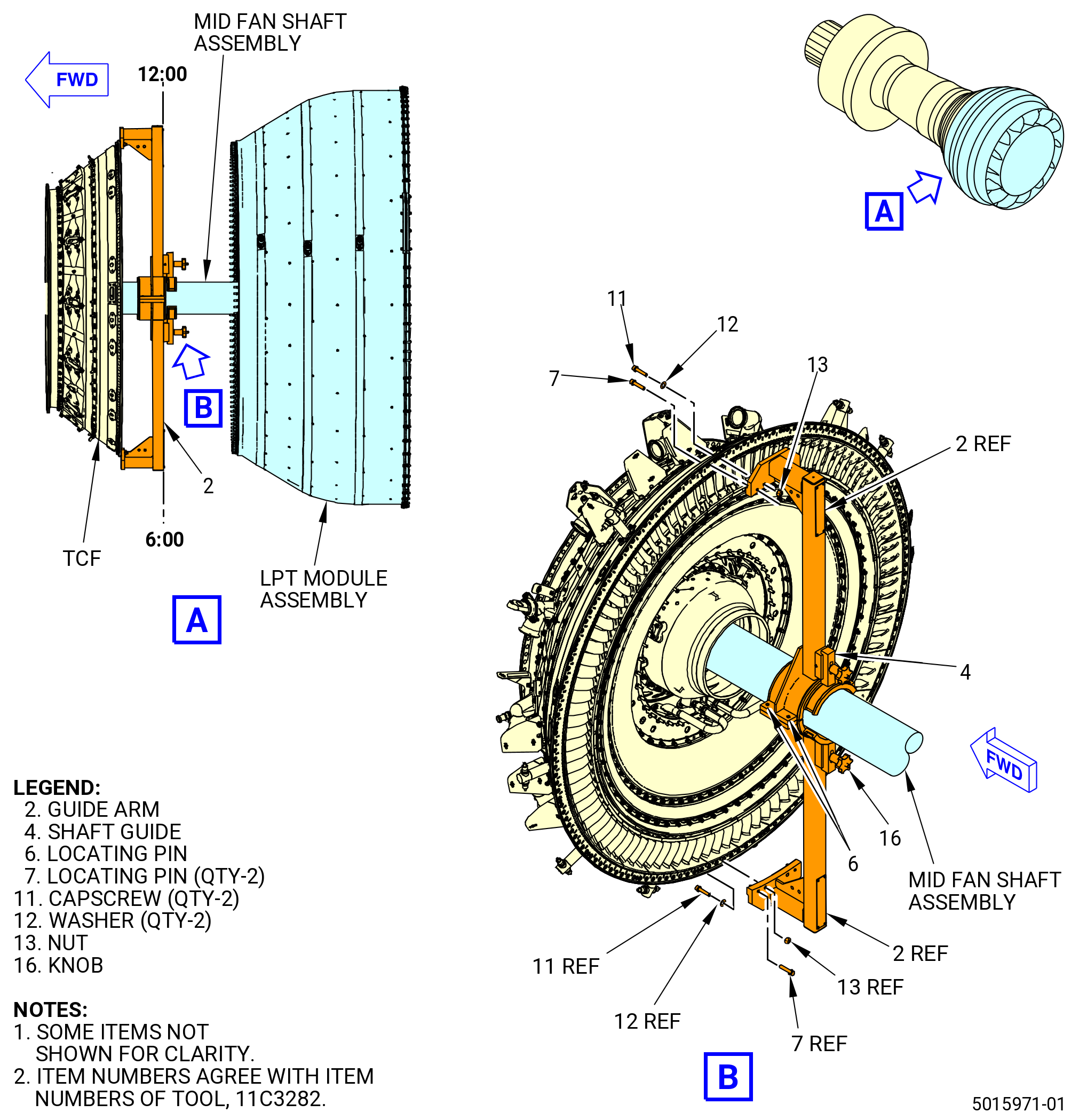
| M. | Install the 11C3282 LPT/TCF guide fixture to the TCF and LPT module assemblies as follows: |
| (1) | After the LPT module assembly is removed approximately 12.0 inches (305 mm) aft, install the 11C3282 LPT/TCF guide fixture. Refer to Figure 330 and do as follows: |
| (a) | Put a guide arm (item 2) on the TCF aft flange at the 6:00 o'clock position with the locating pins (item 7) inserted into the flange boltholes. |
| (b) | Attach the guide arm (item 2) with the capscrew (item 11) and the washer (item 12) on the forward side of the TCF aft flange, and the nut (item 13) on the guide arm. Tighten the nut (item 13). |
| (c) | Attach the second guide arm (item 2) on the TCF aft flange at the 12:00 o'clock position as follows: |
| 1 | Put the locating pins (item 7) inserted into the flange boltholes. |
| 2 | Align the locating pins (item 6) with the guide arm (item 2) at the 6:00 o'clock position. |
| 3 | Attach the guide arm (item 2) with the capscrew (item 11) and the washer (item 12) on the forward side of the TCF aft flange, and the nut (item 13) on the guide arm. Tighten the nut (item 13). |
| (d) | Adjust the shaft guides (item 4) of the 11C3282 LPT/TCF guide fixture against the mid fan shaft assembly and tighten the knob (item 16) to attach the shaft guides (item 4). |
| Subtask 72-00-04-020-044 |
| * * * FOR ALL |
| CAUTION: |
|
| (2) | Continue to move the LPT module assembly aft. Adjust the 9C1147 VCG lift fixture or the 9429M77 lift and turn fixture or the 11C4858 lift and turn fixture as necessary to keep the CG and the hoist weight. Refer to Figure 317. |
| (3) | Make sure not to pull the mid fan shaft assembly and the 11C3283 extension fixture to prevent damage to the propulsor assembly. |
| (4) | When the 11C3283 extension fixture is clear from the propulsor assembly, remove the extension fixture from the mid fan shaft assembly. Refer to Figure 328 and do as follows: |
| CAUTION: |
|
| (a) | Carefully un-thread the extension tube (item 2) by hand to loosen and remove it from the mid fan shaft assembly. |
| WARNING: |
|
| (b) | Add hoist and straps to lift the 11C3283 extension fixture. |
| (c) | Attach the guide tip (item 3) to the forward end of the extension tube (item 2). Safely store the extension fixture. |
| (5) | Remove the guide pins (item 6) of the 9446M40 LPT alignment fixture at four locations from the LPT module assembly front flange. Refer to Figure 327. |
| Subtask 72-00-04-020-013 |
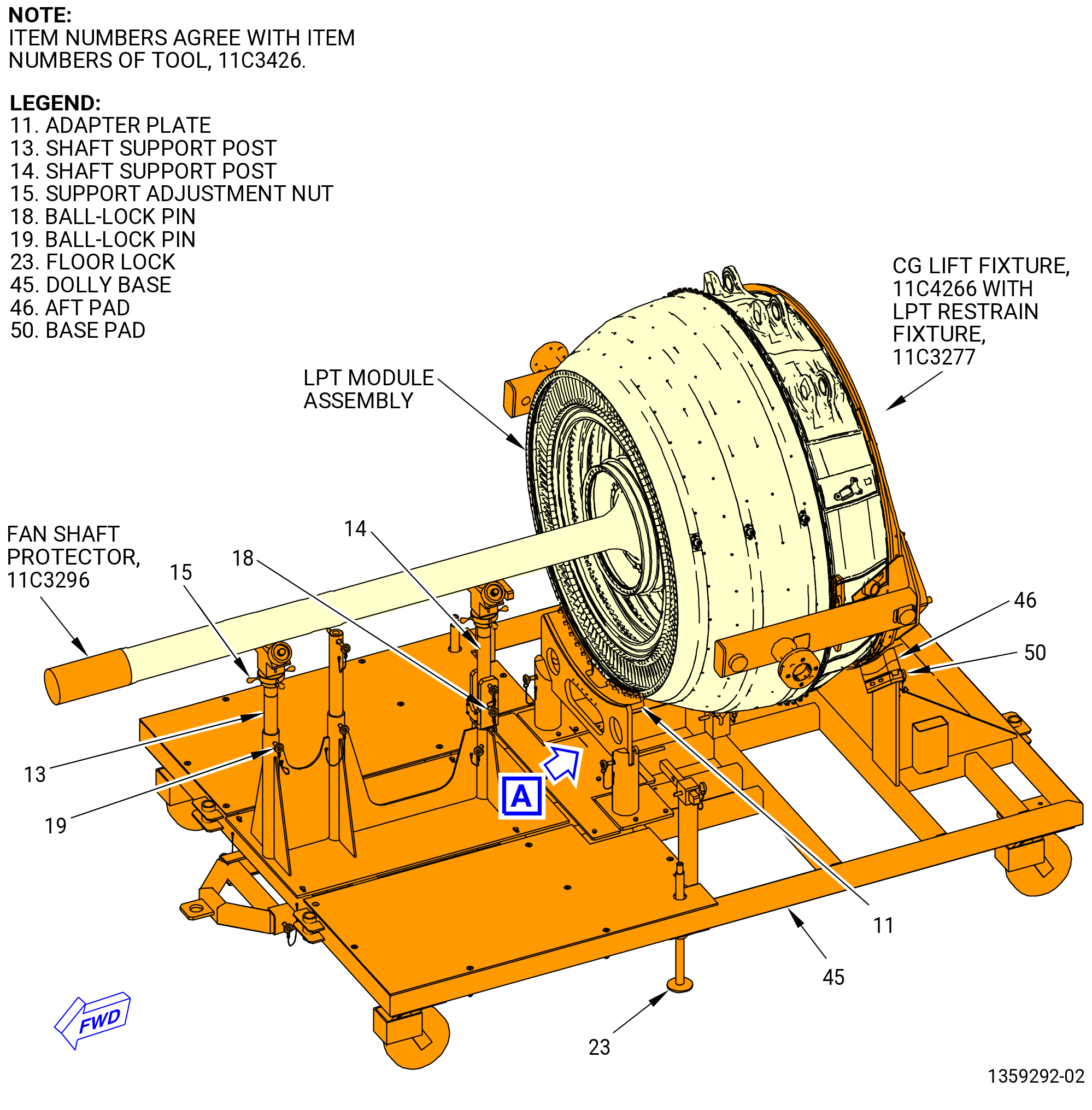
| N. | Install the LPT module assembly on the 11C3426 LPT module dolly. Refer to Figure 331 and do as follows: |
| (1) | Prepare the 11C3426 LPT module dolly as follows: |
| CAUTION: |
|
| (a) | Make sure that the floor locks (item 23) are against the floor. If not, adjust the floor locks against the floor. |
| (b) | Make sure that the shaft support posts (item 13) and (item 14) are in the vertical position and the ball-lock pins (item 18) and (item 19) are installed. |
| WARNING: |
|
| (2) | Install the aft pad (item 48) and the base pad (item 50) and put on each side the two cap screws (item 55). |
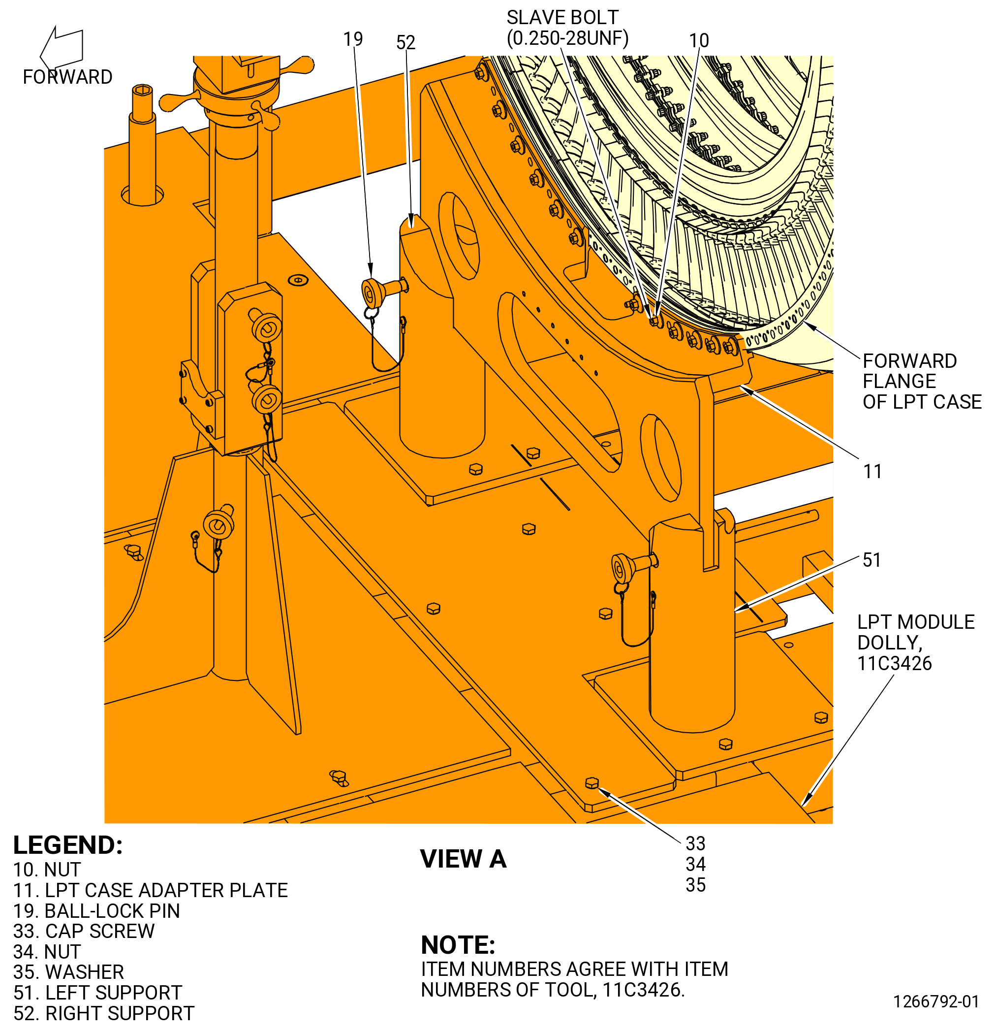
| (3) | Move the forward case left support (item 51) and the forward case right support (item 52) until the stamped arrows, with the word "ENGINE" match with the letters "GENX-1B" stamped on the plate. Put the holes against the dolly base (item 45) and tight with cap screw (item 33), nut (item 34), and flat washer (item 35). |
| (4) | Remove the two ball lock pins (item 19) to remove the adapter plate (item 11) from the dolly base (item 45). |
| (5) | Remove the 12 nuts (item 10) from the adapter plate (item 11). If the nuts (item 10) are too tight, use a wrench 7/16 inches. |
| (6) | Install the adapter plate (item 11) on the LPT studs (93520). Secure it with nuts (item 10) at 12 locations. Use a wrench 7/16 inches. |
| CAUTION: |
|
| (7) | Lower the LPT module assembly in the dolly base (item 45) until the mid fan shaft assembly is in the shaft support post (item 13) and shaft support post (item 14). |
| (8) | Secure the shaft support post (item 13) with one ball-lock pin (item 19) and the shaft support post (item 14) with two ball-lock pins (item 18). |
| (9) | Use the support adjustment nuts (item 15) to adjust the height for the mid fan shaft assembly. |
| * * * FOR ALL |
| Subtask 72-00-04-020-047 |
| * * * FOR ALL |
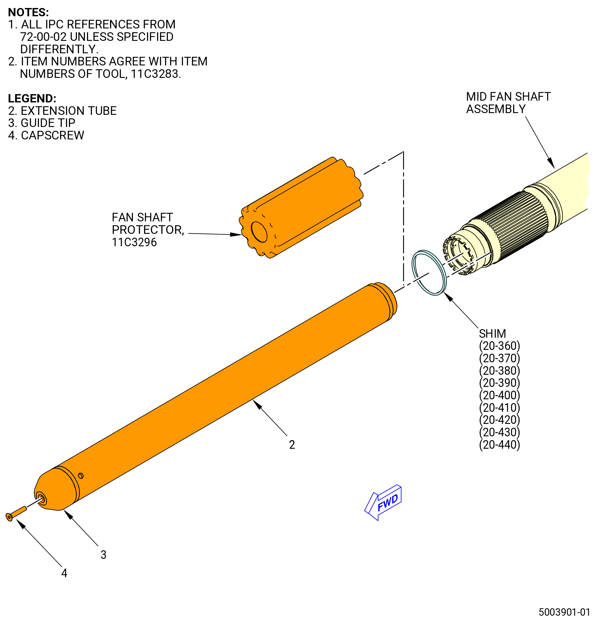
| O. | Remove the 11C3283 extension fixture or 11C4272 extension fixture from the mid fan shaft assembly. Refer to Figure 332 and do as follows: |
| CAUTION: |
|
| (1) | Put a breaker bar in the hole on the forward end of the extension tube (item 2) and remove the extension tube from the mid fan shaft assembly. |
| (2) | Attach the guide tip (item 3) to the extension tube (item 2) with the capscrew (item 4). |
| Subtask 72-00-04-020-063 |
| * * * FOR ALL |
| P. | Install the 11C3296 fan shaft protector on the forward end of the mid fan shaft assembly. |
| Subtask 72-00-04-020-064 |
| * * * FOR ALL |
| Q. | Remove the adjust washer (shim) (20-360 , 72-00-02) (SIN 83070), (20-370 , 72-00-02) (SIN 83070), (20-380 , 72-00-02) (SIN 83070), (20-390 , 72-00-02) (SIN 83070), (20-400 , 72-00-02) (SIN 83070), (20-410 , 72-00-02) (SIN 83070), (20-420 , 72-00-02) (SIN 83070), (20-430 , 72-00-02) (SIN 83070), or (20-440 , 72-00-02) (SIN 83070) from the forward end of the mid fan shaft assembly as follows: |
| (1) | Put the shim in a safe container and make a record of removal. |
| NOTE: |
|
| Subtask 72-00-04-020-048 |
| * * * FOR ALL |
| R. | Remove the 11C5003 push/pull fixture from the 11C3327 LPT mid-shaft guide fixture. Refer to Figure 328. |
| WARNING: |
|
| CAUTION: |
|
| (1) | Lift the 11C5003 push/pull fixture with the nylon tube (item 3) of the 9429M59 breach loader. Refer to Subtask 72-00-04-020-045 (paragraph 3.C.(1)) to install the nylon tube (item 3). |
| Subtask 72-00-04-020-060 |
| * * * FOR ALL |
| S. | Alternative Procedure Available. Use this procedure when the fan booster assembly (20-010 , 72-00-02) (SIN 80000) or (20-011 , 72-00-02) (SIN 80000) has been installed to the fan hub module (25-010 , 72-00-02) (SIN 00102) or (25-011 , 72-00-02) (SIN 00102) or (25-012 , 72-00-02) (SIN 00102). Remove the 11C3327 LPT mid-shaft guide fixture from the fan rotor disk (01-050 , 72-22-00) (SIN 830A0). Refer to Figure 322. |
| WARNING: |
|
| CAUTION: |
|
| (1) | Lift the 11C3327 LPT mid-shaft guide fixture with the nylon tube (item 3) of the 9429M59 breach loader. Refer to Subtask 72-00-04-020-045 (paragraph 3.C.(1)) to install the nylon tube (item 3). |
| (2) | Remove the 11C3084 fan disk protector from the bore of the fan rotor disk and the forward fan shaft (01-170 , 72-24-00) (SIN 81002) or (01-171 , 72-24-00) (SIN 81002). Refer to Figure 322. |
| Subtask 72-00-04-020-061 |
| * * * FOR ALL |
| S.A. | Alternative Procedure. Use this procedure when the fan booster assembly (20-010 , 72-00-02) (SIN 80000) or (20-011 , 72-00-02) (SIN 80000) has not been installed to the fan hub module (25-010 , 72-00-02) (SIN 00102) or (25-011 , 72-00-02) (SIN 00102) or (25-012 , 72-00-02) (SIN 00102). Remove the 11C5013 install/remove fixture from the forward fan shaft (01-170 , 72-24-00) (SIN 81002) or (01-171 , 72-24-00) (SIN 81002) as follows: |
| NOTE: |
|
| WARNING: |
|
| (1) | Remove the 22 cap screws (item 32) and remove the guide adapter (item 5) with a hoist and applicable nylon strap. |
| (2) | Remove the protector (item 8) of the 11C3084 fan disk protector from the bore of the forward fan shaft (01-170 , 72-24-00) (SIN 81002) or (01-171 , 72-24-00) (SIN 81002). Refer to Figure 329. |
| (3) | Remove the capscrews (item 26), the two nut plates (item 3) and the two nut plates (item 4) of the 11C5013 install/remove fixture from the aft side of the forward fan shaft forward flange. |
| Subtask 72-00-04-020-027 |
| T. | To continue disassembly of the LPT module assembly, refer to TASK 72-00-04-030-801 (72-00-04, DISASSEMBLY 001). |
| Subtask 72-00-04-020-062 |
| * * * FOR ALL |
| U. | To continue disassembly of the engine, refer to TASK 72-00-02-030-803 (72-00-02, DISASSEMBLY 003). |