| GENX-1B ENGINE MANUAL | Dated: 01/29/2025 | |
| EM 72-00-04 , DISASSEMBLY 001 | ||
| LOW PRESSURE TURBINE MODULE ASSEMBLY - DISASSEMBLY 001 | ||
| GENX-1B ENGINE MANUAL | Dated: 01/29/2025 | |
| EM 72-00-04 , DISASSEMBLY 001 | ||
| LOW PRESSURE TURBINE MODULE ASSEMBLY - DISASSEMBLY 001 | ||
| * * * FOR ALL |
| TASK 72-00-04-030-801 |
| * * * FOR ALL |
| 1 . | General. |
| A. | This procedure gives instructions to disassemble the low pressure turbine (LPT) module assembly. Refer to Figure 501. |
| • |
|
| • |
|
| • |
|
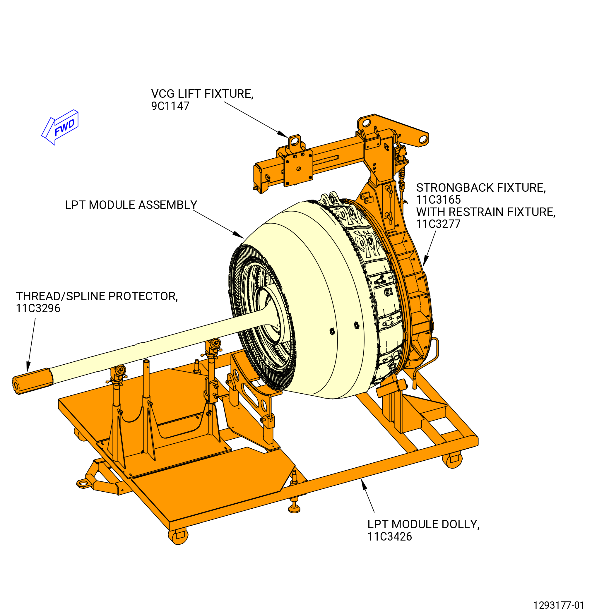
| B. | This procedure starts with the LPT module assembly and mid fan shaft assembly on the 11C3426 LPT module dolly with the 9C1147 VCG lift fixture and the 11C3165 strongback or the 11C4266 CG lift fixture and the 11C3277 restrain fixture and the 11C3296 thread/spline protector installed. Refer to Figure 502. |
| • |
|
| • |
|
| • |
|
| • |
|
| NOTE: |
|
| WARNING: |
|
| WARNING: |
|
| WARNING: |
|
| C. | Before installation, make sure that all the flange surfaces, the tools, or the assembly parts are free of foreign material. Clean when you are instructed with C04-002 Stoddard solvent, C04-003 acetone, C04-035 isopropyl alcohol, or a 50-50 blend of alcohol and water. |
| D. | Protective covers must be installed on spare assemblies only. |
| E. | If an axisymmetric rotating part with a visible crack through the axial or radial thickness of the part feature is found during the disassembly procedure, then the mating Life Limited Part(s) (LLP) can be affected. The mating LLP must be considered not serviceable and not repairable. |
| NOTE: |
|
| NOTE: |
|
| 2 . | Tools, Equipment, and Materials. |
| NOTE: |
|
| A. | Tools and Equipment. |
| (1) | Special Tools. |
| (2) | Standard Tools and Equipment. |
|
| (3) | Locally Manufactured Tools. None. |
| B. | Consumable Materials. |
|
| C. | Referenced Procedures. |
|
| D. | Expendable Parts. None. |
| * * * FOR ALL |
| 3 . | Procedure. |
| Subtask 72-00-04-030-027 |
| * * * FOR ALL |
| A. | Remove the air extension duct (extension duct) from the LPT cone shaft as follows. Refer to Figure 503. |
| (1) | Install the 11C3328 air duct extension tool to remove the extension duct as follows: |
| (a) | Put vinyl-backed tape on the extension duct labyrinth seal in the No. 5 bearing housing (01501) to protect the extension duct from damage by the 11C3328 air duct extension tool. |
| (b) | Install the guide ring (item 13) on the studs in the No. 5 bearing housing aft flange and attach it with plain nuts (item 26) at 20 locations. |
| (c) | Install the guide ring (item 13) on the aft flange studs of the No. 5 bearing housing and attach it with the plain nuts (item 26) at 20 locations. |
| (d) | Install the housing (item 32) onto the guide ring (item 13). Turn the housing clockwise (CW) by hand to thread the housing onto the LPT cone shaft. |
| (e) | Align the center of one of the three tabs in the LPT cone shaft with one of the four lines in the housing (item 32). |
| (f) | Lift the clamp outer tube (item 40), locking outer tube (item 3) and pusher/puller tube (item 37) and slide them forward of the pusher tube (item 30). Put the tabs at the forward end of the pusher/puller tube (item 37) through the internal slots in the aft end of the extension duct. |
| (g) | Make sure that the aft notch on the outside diameter (OD) of the locking outer tube (item 3) aligns with one of the three tabs in the extension duct. |
| (h) | Turn the pusher/puller tube (item 37) one-half tooth spacing and slide the locking outer tube (item 3) forward. This will engage the two tabs on the forward end of the locking outer tube (item 3) between the corresponding slots in the extension duct. |
| (i) | Tighten the clamp outer tube (item 40) CW against the aft face of extension duct outer rail. |
| (j) | Install the cylinder support (item 38) and attach it with two ball lock pins (item 19) to the housing (item 32) at two locations. |
| (k) | Install the hydraulic cylinder (item 21) over the pusher tube (item 30) rod so the piston points aft. |
| (2) | Remove the extension duct and the 11C3328 air duct extension tool as follows: |
| (a) | Attach the hydraulic hand pump to the hydraulic coupler assembly (item 22) on the hydraulic cylinder (item 21). Fully close the piston. |
| (b) | Install the plain washer (item 27) and the plain nut (item 25) on the aft end of the pusher tube (item 30) rod until they are against the hydraulic cylinder (item 21). |
| (c) | Attach the cylinder protector (item 34) to the cylinder support (item 38) with two cap screws (item 43). |
| WARNING: |
|
| CAUTION: |
|
| (d) | Apply pump pressure until the extension duct is loose. Do not use more than 6000 PSI (41368 KPa) pressure to prevent damage to the extension duct. |
| (e) | Release the pressure from the hydraulic cylinder (item 21) until the piston is fully retracted. |
| (f) | Disconnect the hydraulic hand pump from the hydraulic cylinder (item 21). |
| (g) | Remove the nut (item 25) and the plain washer (item 27) from the pusher tube (item 30). |
| (h) | Remove the hydraulic cylinder (item 21). |
| (i) | Remove the ball lock pins (item 19) at two locations and remove the cylinder support (item 38). |
| (j) | Remove the extension duct from the LPT cone shaft. |
| (k) | Loosen the clamp outer tube (item 40). |
| (l) | Pull the locking outer tube (item 3) and turn the pusher/puller tube (item 37) one half tooth spacing until it slides out. |
| (m) | Turn the housing (item 32) counterclockwise (CCW) and remove it. |
| (n) | Remove the plain nuts (item 26) at 20 locations and the guide ring (item 13) from the studs on the No. 5 bearing housing aft flange. |
| (o) | Remove the vinyl-backed tape from the extension duct labyrinth seal in the No. 5 bearing housing. |
| * * * FOR ALL |
| Subtask 72-00-04-030-001 |
| * * * FOR ALL |
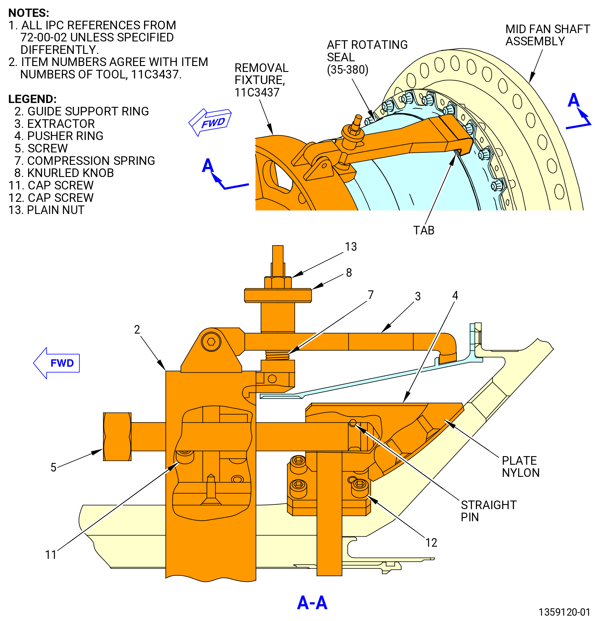
| B. | Remove the No. 4 bearing aft rotating seal (aft rotating seal) (01406) from the mid fan shaft assembly as follows. Refer to Figure 504. |
| (1) | Remove the 24 bolts (01423) from the aft rotating seal and the mid fan shaft assembly. |
| (2) | Use the 11C3437 removal fixture to remove the aft rotating seal from the mid fan shaft assembly as follows. Refer to Figure 505. |
| WARNING: |
|
| (a) | Install the extractor (item 3) and pusher ring (item 4) of the 11C3437 removal fixture on the mid fan shaft assembly. |
| NOTE: |
|
| (b) | Use the straight pins and the pusher ring (item 4) as a guide to install the guide support ring (item 2) with the extractor (item 3) and the pusher ring (item 4) already in place. |
| (c) | Install and torque the cap screws (item 11) to 18-22 lb in. (2.0-2.5 N.m). |
| (d) | Install and torque the cap screws (item 12) to 18-22 lb in. (2.0-2.5 N.m). |
| (e) | Align the extractors (item 3) with the aft rotating seal (35-380 , 72-00-02) (SIN 01406) tabs and pull the assembly until the nylon plate touches the mid fan shaft assembly. |
| NOTE: |
|
| (f) | Close the extractors (item 3) against the aft rotating seal (01406) tabs by tightening the knurled knobs (item 8) by hand. The extractor tip must be contained between the aft rotating seal flange and the lip. |
| (g) | Tighten the plain nuts (item 13) to secure the knurled knobs (item 8). |
| (h) | Tighten the screws (item 5) with a standard spanner wrench in a criss-cross pattern and remove the aft rotating seal from the mid fan shaft assembly. |
| Subtask 72-00-04-030-026 |
| * * * FOR ALL |
| C. | Attach the 11C3600 mid fan shaft lift fixture to the mid fan shaft assembly as follows. Refer to Figure 506. |
| NOTE: |
|
| (1) | Remove the slings (item 3) from the safety hooks (item 4). |
| (2) | Attach the slings (item 3) at two locations to the mid fan shaft assembly. Double the sling straps around the shaft. |
| (3) | Attach an overhead hoist to the spreader bar (bar) (item 2) at two locations. |
| WARNING: |
|
| (4) | Lift the bar (item 2) with an overhead hoist and attach the slings (item 3) to the safety hooks (item 4). |
| (5) | Remove unwanted slack from the slings (item 3) with the overhead hoist. |
| Subtask 72-00-04-030-004 |
| * * * FOR ALL |
| D. | Remove the mid fan shaft assembly from the LPT module assembly as follows: |
| (1) | Adjust the 11C3426 LPT module dolly as follows. Refer to Figure 502. |
| (a) | Make sure that the hold-down clamps are not attached around the mid fan shaft assembly. Release the hold-down clamps or temporarily remove the hold-down clamps from the shaft support post (item 14) of the 11C3426 LPT module dolly. |
| (b) | Find the shaft support post (item 14) in the middle of the LPT dolly. |
| (c) | Pull the ball-lock pin (item 18) from the shaft support post (item 14) on the LPT dolly. |
| (d) | Turn the shaft support post (item 14) forward and down and away from the mid fan shaft assembly. Insert the ball-lock pin (item 18) of the 11C3426 LPT module dolly again. |
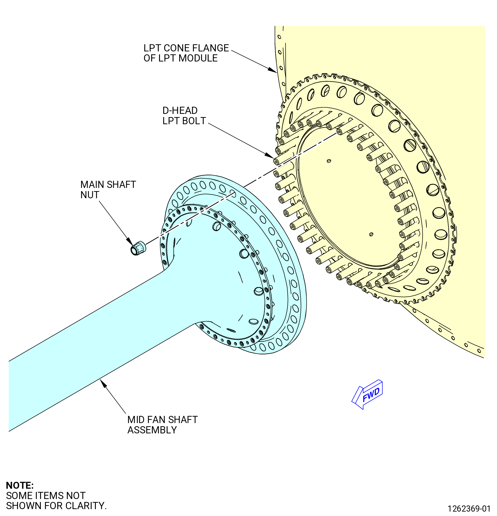
| (2) | Remove and discard the main shaft nuts (45-390 , 72-00-02) (SIN 93040) from the mid fan shaft assembly. Refer to Figure 507. |
| Subtask 72-00-04-440-002 |
| * * * FOR ALL |
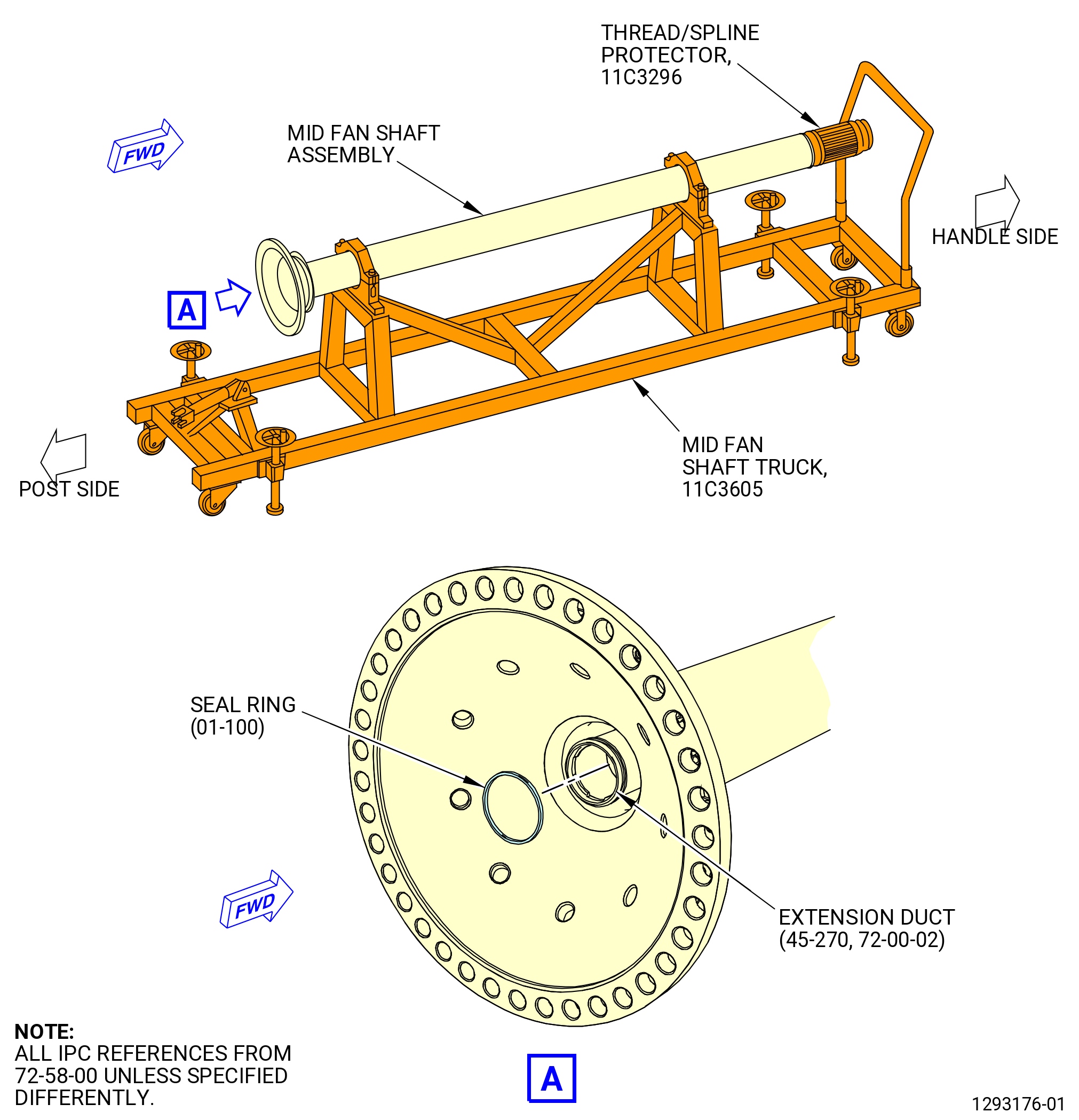
| E. | Install the mid fan shaft assembly on the 11C3605 mid fan shaft truck as follows. Refer to Figure 508. |
| (1) | Prepare the 11C3605 mid fan shaft truck for the mid fan shaft assembly as follows: |
| (a) | Loosen the nuts (item 28) and remove the eye bolts (item 39) that attach the upper plates (item 15) to the lower plates (item 16). |
| (b) | Remove the upper plates (item 15) from the lower plates (item 16). |
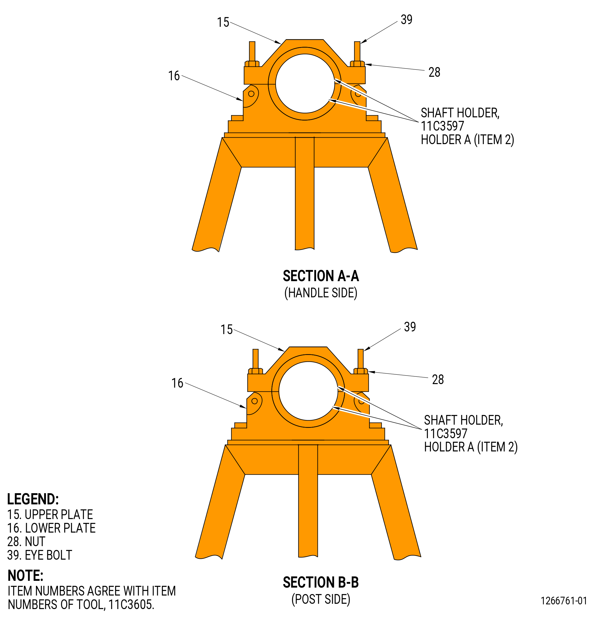
| (c) | Install the 11C3597 shaft holder to the 11C3605 mid fan shaft truck as follows: |
| 1 | Install the holders A (item 2) of 11C3597 shaft holder to the upper plate (item 15) and the lower plate (item 16) (in the handle side) of the 11C3605 mid fan shaft truck with the screws (item 27). |
| 2 | Install the holders B (item 3) of 11C3597 shaft holder to the upper plate (item 15) and the lower plate (item 16) (in the post side) of the 11C3605 mid fan shaft truck with the screws (item 27). |
| WARNING: |
|
| CAUTION: |
|
| (2) | Carefully lift the mid fan shaft assembly from the 11C3426 LPT module dolly. |
| (3) | Install the mid fan shaft assembly onto the 11C3605 mid fan shaft truck. Refer to Figure 508 and do as follows: |
| NOTE: |
|
| (a) | Move the 11C3605 mid fan shaft truck under the mid fan shaft assembly. |
| (b) | Remove the handle (item 3) from the mid fan shaft truck. |
| (c) | Make sure that the post (item 9) is lowered. |
| (d) | Carefully lower the mid fan shaft assembly onto the lower plates (item 16), with the aft end of the mid fan shaft assembly to the post side. |
| (4) | Attach the mid fan shaft assembly to the 11C3605 mid fan shaft truck as follows: |
| CAUTION: |
|
| (a) | Put the upper plates (item 15) with the holder A (item 2) of the 11C3597 shaft holder on the lower plates (item 16) in the handle side of the 11C3605 mid fan shaft truck. |
| CAUTION: |
|
| (b) | Put the upper plates (item 15) with the holder B (item 3) of the 11C3597 shaft holder holder on the lower plates (item 16) in the post side of the 11C3605 mid fan shaft truck. |
| (c) | Install the eye bolts (item 39) and manually tighten the nuts (item 28) to attach the upper plates (item 15) to the lower plates (item 16). |
| (5) | Remove the 11C3600 mid fan shaft lift fixture from the mid fan shaft assembly. |
| Subtask 72-00-04-030-028 |
| * * * FOR ALL |
| F. | Remove and discard the seal ring (01-100 , 72-58-00) (SIN 810N5) from the center vent duct. Refer to Figure 509. |
| Subtask 72-00-04-440-003 |
| * * * FOR ALL |
| G. | Alternative Procedure Available. Remove the LPT module assembly from the 11C3426 LPT module dolly as follows. The 9C1147 VCG lift fixture, the 11C3165 strongback, and the 11C3277 restrain fixture are installed on the LPT module assembly. |
| NOTE: |
|
| CAUTION: |
|
| (1) | Make sure that the floor locks (item 23) of the 11C3426 LPT module dolly, are against the floor. If not, lower the floor locks (item 23) and lock in place. Refer to Figure 502. |
| (2) | Attach an overhead hoist to the bracket hoist of the 9C1147 VCG lift fixture. Make sure that the VCG lift fixture center of gravity is set to 1.50 inches (38.1 mm). |
| (3) | Lift the LPT module assembly with the 9C1147 VCG lift fixture sufficiently to remove the ball-lock pins (item 19) from the forward case supports (item 5). Refer to Figure 502. |
| (4) | Lift the LPT module assembly from the 11C3426 LPT module dolly with the 9C1147 VCG lift fixture. If necessary, adjust the VCG lift fixture to correct the center of gravity for the LPT module assembly. |
| (5) | Remove the 11C3426 LPT module dolly from the LPT module assembly. |
| (6) | Remove the nuts (item 10) and slave bolts from the LPT case forward flange. |
| (7) | Remove the LPT case adapter plate (item 11) of the 11C3426 LPT module dolly from the LPT case forward flange. |
| (8) | Attach a second overhead hoist to the hoist rings of the 11C3165 strongback at two locations. Refer to Figure 510. |
| (9) | Lift the LPT module assembly with the 11C3165 strongback and use the two lift hoists to rotate the LPT module assembly to the vertical position, forward end down. |
| Subtask 72-00-04-440-013 |
| * * * FOR ALL |
| G.A. | Alternative Procedure. Remove the LPT module assembly from the 11C3426 LPT module dolly as follows: |
| NOTE: |
|
| CAUTION: |
|
| (1) | Make sure that the floor locks (item 23) of the 11C3426 LPT module dolly are against the floor. If not, lower the floor locks (item 23) and lock in place. Refer to Figure 502. |
| (2) | Prepare two cranes and two 9429M77 lift and turn fixtures. |
| (3) | Attach two wires of the first 9429M77 lift and turn fixture to the pivot trunnions located on the aft side of the 11C4266 CG lift fixture (aft side of the LPT module). |
| (4) | Attach two wires of the second 9429M77 lift and turn fixture to the pivot trunnions located on the fwd side of the 11C4266 CG lift fixture (fwd side of the LPT module). |
| WARNING: |
|
| (5) | Lift the LPT module assembly with two 9429M77 lift and turn fixtures sufficient to remove the ball-lock pins (item 19) from the forward case supports (item 5). |
| (6) | Lift the LPT module assembly from the 11C3426 LPT module dolly with the 9429M77 lift and turn fixture. If necessary, adjust the lift and turn fixture to correct the center of gravity for the LPT module assembly. |
| (7) | Remove the nuts (item 10) and slave bolts from the LPT case forward flange. |
| (8) | Remove the LPT case adapter plate (item 11) of the 11C3426 LPT module dolly from the LPT case forward flange. |
| (9) | Lock the first 9429M77 lift and turn fixture attached to the aft pivot trunnions. |
| (10) | Lower the second 9429M77 lift and turn fixture attached to the fwd pivot trunnions to turn the LPT module assembly to the fully vertical position, forward end down. |
| Subtask 72-00-04-030-007 |
| H. | Alternative Procedure Available. Install the LPT module assembly on the 11C3520 LPT rotor/stator buildup stand as follows. Refer to Figure 511. |
| (1) | Lower the plate (item 62) with the tool B (drive socket) (item 36) of the 11C3520 LPT rotor/stator buildup stand. |
| WARNING: |
|
| (2) | Lift the LPT module assembly and install it on the 11C3520 LPT rotor/stator buildup stand. |
| (3) | Slowly lift the plate (item 62) until the weight of the LPT rotor can be held by the plate. |
| (4) | Remove the 9C1147 VCG lift fixture as follows. Refer to Figure 502. |
| NOTE: |
|
| (a) | Remove the lift hoist from the lift eye (item 65) of the 9C1147 VCG lift fixture. |
| (b) | Attach the lift hoist to the hoist bracket (item 60) vertical hole. |
| (c) | Apply a lift tension to the VCG lift fixture and remove the pin (item 35) at two locations. |
| (d) | Lift the VCG lift fixture from the LPT module assembly. |
| (5) | Remove the 11C3277 restrain fixture from the LPT module assembly as follows: |
| (a) | Disengage the pilot tube (item 17) from the housing nut (item 19). |
| (b) | Remove the pilot tube (item 17) from the restrain fixture (item 2). |
| (c) | Remove the restrain fixture (item 2). |
| (d) | Remove the housing nut (item 19) from the LPT module assembly. |
| * * * FOR ALL |
| Subtask 72-00-04-030-029 |
| * * * FOR ALL |
| H.A. | Alternative Procedure. Install the LPT module assembly on the 11C3520 LPT rotor/stator buildup stand. Refer to Figure 512 and do as follows: |
| (1) | Lower the plate (item 62) with the tool B (drive socket) (item 36) of the 11C3520 LPT rotor/stator buildup stand. |
| WARNING: |
|
| (2) | Lift the LPT module assembly and install it on the 11C3520 LPT rotor/stator buildup stand. |
| (3) | Slowly lift the plate (item 62) until the weight of the LPT rotor can be held by the plate. |
| (4) | Remove the 11C4266 CG lift fixture from the LPT module assembly. |
| (5) | Remove the 11C3277 restrain fixture from the LPT module assembly as follows: |
| (a) | Disengage the pilot tube (item 17) from the housing nut (item 19). |
| (b) | Remove the pilot tube (item 17) from the restrain fixture (item 2). |
| (c) | Remove the restrain fixture (item 2). |
| (d) | Remove the housing nut (item 19) from the LPT module assembly. |
| Subtask 72-00-04-030-017 |
| * * * FOR ALL |
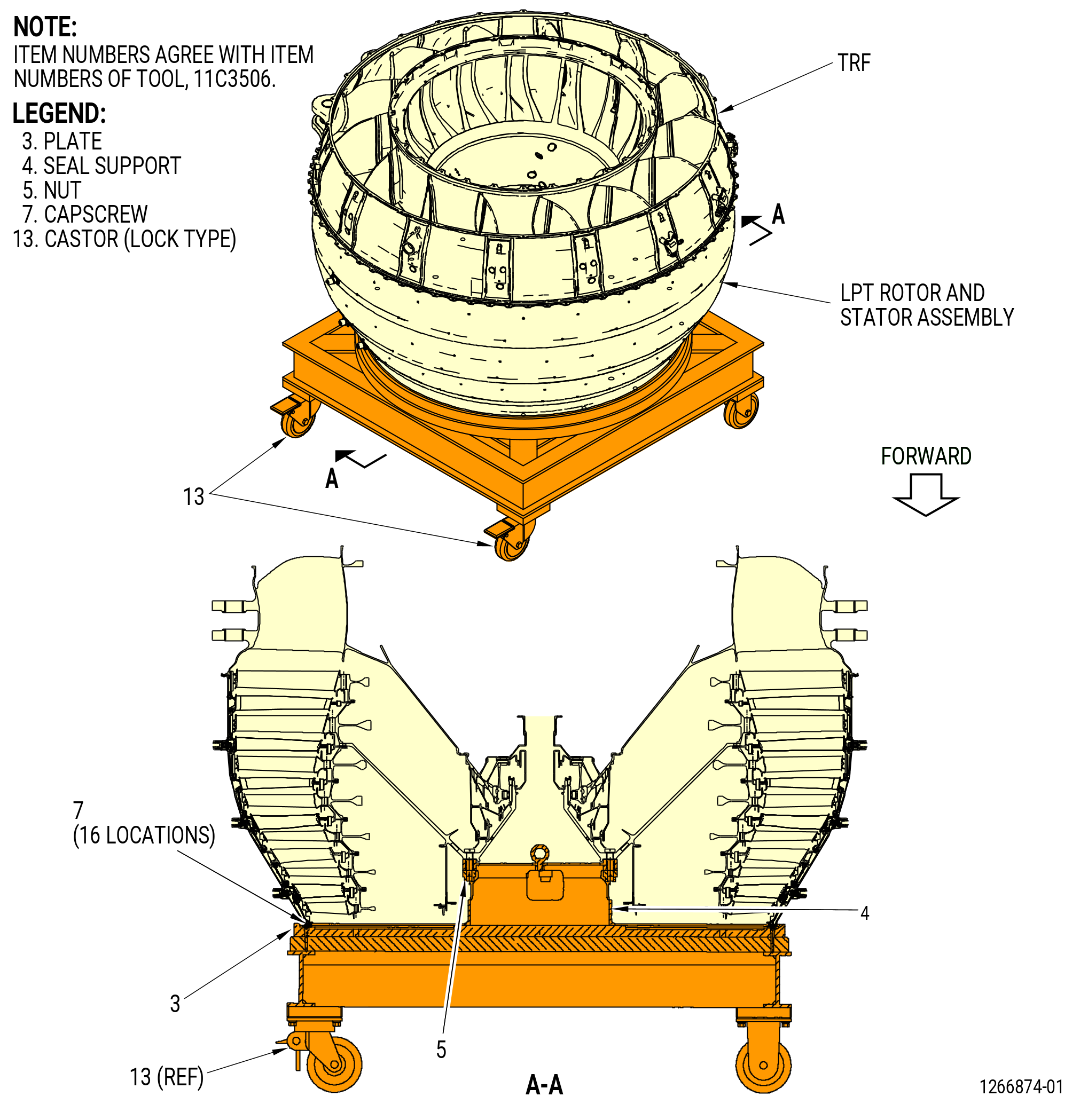
| H.B. | Alternative Procedure. Install the LPT module assembly on the 11C3506 LPT module transport/storage stand as follows. Refer to Figure 513. |
| (1) | Prepare the LPT module assembly as follows: |
| (a) | Install the seal support (item 4) of the 11C3506 LPT module transport/storage stand to the LPT cone shaft D-head bolts. The LPT module assembly must be on the 11C3520 LPT rotor/stator buildup stand to install the seal support (item 4) of the 11C3506 LPT module transport/storage stand. If necessary, refer to Subtask 72-00-04-030-007 (paragraph 3.H.) to install the LPT module assembly on the LPT rotor/stator buildup stand. |
| (b) | Attach the seal support to the LPT cone shaft with the nuts (item 5) of the 11C3506 LPT module transport/storage stand. |
| WARNING: |
|
| (2) | Lift the LPT module assembly from the 11C3520 LPT rotor/stator buildup stand with an overhead hoist attached to the hoist rings (item 10) of the 11C3165 strongback at two locations. Refer to Figure 511. |
| (3) | Install the LPT module assembly onto the 11C3506 LPT module transport/storage stand. Refer to Figure 513. |
| (4) | Remove the 11C3165 strongback from the LPT module assembly. |
| (5) | Remove the 11C3277 restrain fixture from the LPT module assembly as follows: |
| (a) | Disengage the pilot tube (item 17) from the housing nut (item 19). |
| (b) | Remove the pilot tube (item 17) from the restrain fixture (item 2). |
| (c) | Remove the restrain fixture (item 2). |
| (d) | Remove the housing nut (item 19) from the LPT module assembly. |
| Subtask 72-00-04-030-030 |
| * * * FOR ALL |
| H.C. | Alternative Procedure. Install the LPT module assembly on the 11C3506 LPT module transport/storage stand. Refer to Figure 513 and do as follows: |
| (1) | Prepare the LPT module assembly as follows: |
| (a) | Install the seal support (item 4) of the 11C3506 LPT module transport/storage stand to the LPT cone shaft D-head bolts. The LPT module assembly must be on the 11C3520 LPT rotor/stator buildup stand to install the seal support (item 4) of the 11C3506 LPT module transport/storage stand. If necessary, refer to Subtask 72-00-04-030-007 (paragraph 3.H.) to install the LPT module assembly on the LPT rotor/stator buildup stand. |
| (b) | Attach the seal support to the LPT cone shaft with the nuts (item 5) of the 11C3506 LPT module transport/storage stand. |
| (c) | Tighten the nuts (item 5). |
| CAUTION: |
|
| (2) | Make sure that the locks on the castors (item 13) are in the locked position. |
| WARNING: |
|
| (3) | Lift the LPT module assembly from the 11C3520 LPT rotor/stator buildup stand with the 9429M77 lift and turn fixture attached to the aft pivot trunnions (item 22 and 23) of the 11C4266 CG lift fixture at two locations. Refer to Figure 512. |
| (4) | Install the LPT module assembly on the 11C3506 LPT module transport/storage stand as follows: |
| (a) | Lower the LPT module assembly on the plate (item 3). |
| (b) | Attach the LPT module assembly to the plate with the capscrews (item 7) at 16 locations. |
| (5) | Remove the 11C4266 CG lift fixture from the LPT module assembly. |
| (6) | Remove the 11C3277 restrain fixture from the LPT module assembly as follows: |
| (a) | Disengage the pilot tube (item 17) from the housing nut (item 19). |
| (b) | Remove the pilot tube (item 17) from the restrain fixture (item 2). |
| (c) | Remove the restrain fixture (item 2). |
| (d) | Remove the housing nut (item 19) from the LPT module assembly. |
| Subtask 72-00-04-030-010 |
| I. | Remove the brackets and hardware from the LPT rotor/stator assembly aft flange and the TRF forward flange. Discard the self-locking nut (nut) (01-060) (SIN 94040). Refer to Figure 514. |
| * * * FOR ALL |
| * * * FOR ALL |
| Subtask 72-00-04-030-011 |
| J. | Remove the TRF from the LPT rotor/stator assembly as follows: |
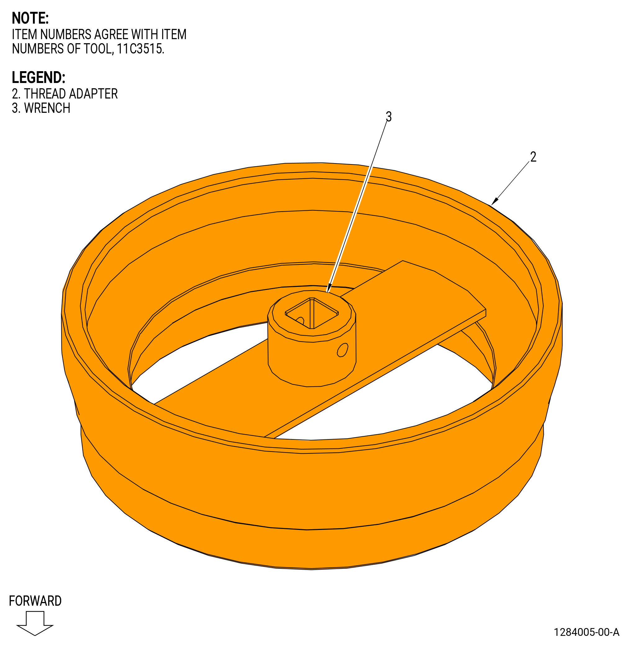
| (1) | Install the 11C3515 thread adapter on the aft end of the LPT cone shaft. Refer to Figure 515 and do as follows: |
| (a) | Install the thread adapter (item 2) to the aft threads of the LPT cone shaft. |
| (b) | Attach the wrench (item 3) to the thread adapter (item 2). |
| (c) | Use a wrench to tighten the thread adapter (item 2). |
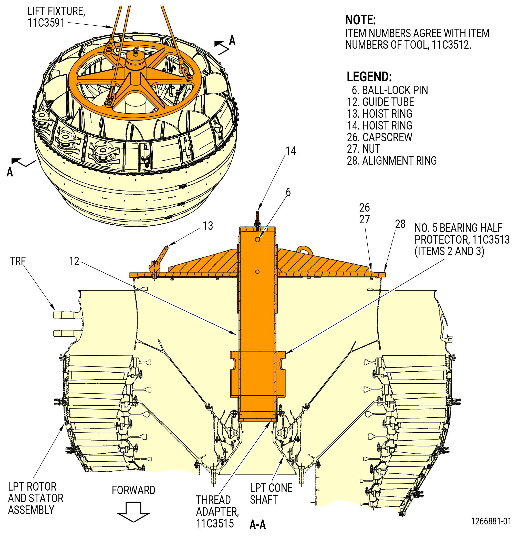
| (2) | Install the 11C3512 TRF guide fixture to the TRF assembly as follows. Refer to Figure 516. |
| NOTE: |
|
| (a) | Clean the forward threads of the guide tube (item 12). |
| (b) | Attach a hoist to the hoist ring (item 14) on the guide tube (item 12). |
| (c) | Lift the guide tube (item 12) with the hoist. |
| (d) | Lower the guide tube (item 12) into the TRF until the forward end of the guide tube touches the 11C3515 thread adapter that is installed on the aft threads of the LPT cone shaft. |
| (e) | Turn the guide tube (item 12) of the 11C3512 TRF guide fixture CW by hand until the threads of the guide tube fully engage with the threads of the 11C3515 thread adapter. |
| (f) | Remove the hoist from the guide tube (item 12) of the 11C3512 TRF guide fixture. |
| WARNING: |
|
| (g) | Lubricate the outer diameter of the guide tube (item 12) with C02-019 engine oil or C02-023 engine oil. |
| (h) | Install the 11C3513 No. 5 bearing protector to the aft inner flange of the No. 5 bearing support housing around the guide tube (item 12) of the 11C3512 TRF guide fixture and onto the 11C3515 thread adapter. |
| (i) | Attach the 11C3591 vertical lift fixture to the hoist rings (item 13) of the 11C3512 TRF guide fixture at three locations on the alignment ring (item 28). |
| (j) | Attach an overhead hoist to the sling assembly (item 2) of the 11C3591 vertical lift fixture. |
| WARNING: |
|
| (k) | Lift the alignment ring (item 28) of the 11C3512 TRF guide fixture and install it on the aft inner flange of the TRF assembly. Align the TOP mark with the top vertical centerline of the TRF. |
| (l) | Attach the alignment ring (item 28) to the TRF with the capscrews (item 26) and the nuts (item 27) at nine locations. Do not fully tighten the nuts at this time. |
| (m) | Tighten the nuts (item 27) to hold the alignment ring (item 28). |
| (3) | Install the 11C3530 lift fixture to the aft end of the TRF as follows. Refer to Figure 517. |
| (a) | Attach the sling assembly (item 6) to an overhead hoist. |
| (b) | Turn the pins (item 4) CCW and pull them out from the from the hook block (item 2). |
| (c) | Attach the hook blocks (item 2) to the aft outer flange of the TRF assembly at three equally spaced positions as follows: |
| 1 | Align the holes in the hook blocks (item 2) with the holes in the aft outer flange of the TRF assembly. |
| 2 | Install the pins (item 4) into the hook blocks (item 2). Manually tighten the pins. |
| (4) | Remove the remaining bolts from all boltholes on the TRF and LPT module flange. |
| * * * FOR ALL |
| Subtask 72-00-04-030-020 |
| * * * FOR ALL |
| (5) | Install the 11C3516 bracket set to the TRF before you remove the TRF from the LPT rotor/stator assembly as follows. Refer to Figure 518. |
| CAUTION: |
|
| (a) | Install the movable bar (item 2) and the stationary bar (item 3) at the 9:00 o'clock position on the TRF as follows: |
| 1 | Adjust the movable bar (item 2) in by turning the knob (item 8). |
| 2 | Align the holes on the stationary bar (item 3) with the holes on the aft side of the forward flange. Do not attach the stationary bar until you remove the TRF from the LPT rotor/stator assembly. |
| 3 | Adjust the movable bar (item 2) out by turning the knob (item 8). |
| 4 | Align the holes on the movable bar (item 2) with the holes on the forward side of the TRF aft flange. |
| 5 | Install the movable bar (item 2) to the TRF with the screws (item 9), nuts (item 11), and washers (item 12) at three locations. Do not tighten the nuts (item 11) at this time. |
| CAUTION: |
|
| (b) | Install the movable bar (item 4) and the stationary bar (item 5) at the 3:00 o'clock position on the TRF as follows: |
| 1 | Adjust the movable bar (item 4) in by turning the knob (item 8). |
| 2 | Align the holes on the stationary bar (item 5) with the holes on the aft side, in the forward flange, of the TRF. Do not attach the stationary bar until you remove the TRF from the LPT rotor/stator assembly. |
| 3 | Adjust the movable bar (item 4) out by turning the knob (item 8). |
| 4 | Align the holes on the movable bar (item 4) with the holes on the forward side of the TRF aft flange. |
| 5 | Install the movable bar (item 4) to the TRF assembly with the screws (item 9), nuts (item 11), and washers (item 12) at three locations. Do not tighten the nuts (item 11) at this time. |
| Subtask 72-00-04-030-021 |
| * * * FOR ALL |
| WARNING: |
|
| CAUTION: |
|
| (6) | Slowly lift the TRF from the LPT rotor/stator assembly. |
| NOTE: |
|
| Subtask 72-00-04-030-022 |
| * * * FOR ALL |
| (7) | Install the stationary bar (item 3) to the TRF with the screws (item 9), nuts (item 11), and washers (item 12) at four locations. |
| (8) | Tighten the nuts (item 11) to secure the movable bar (item 2) and the stationary bar (item 3) to the TRF. |
| (9) | Install the stationary bar (item 5) to the TRF with the screws (item 9), nuts (item 11), and washers (item 12) at four locations. |
| (10) | Tighten the nuts (item 11) to secure the movable bar (item 4) and the stationary bar (item 5) to the TRF. |
| Subtask 72-00-04-030-018 |
| * * * FOR ALL |
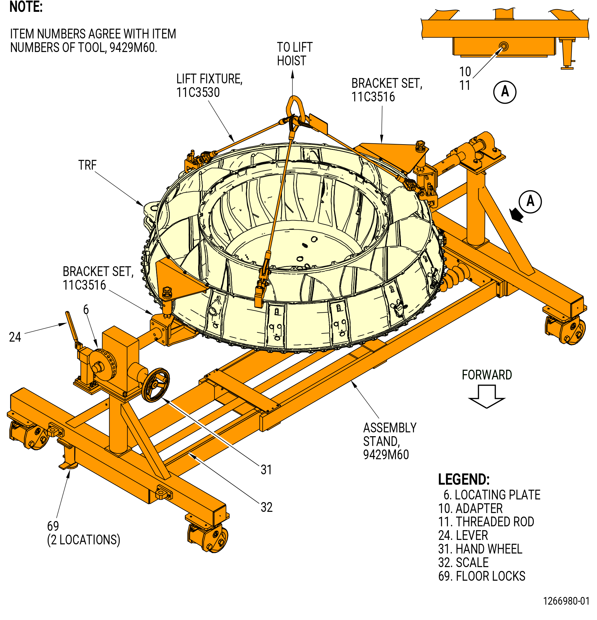
| K. | Install the TRF on the 9429M60 roll-over stand as follows. The 11C3516 bracket set must be installed on the TRF at the 3:00 and 9:00 o'clock positions. Refer to Figure 519. |
| NOTE: |
|
| (1) | If necessary, adjust the length of the roll-over stand. Turn the adapter (item 10) attached to the threaded rod (item 11) to adjust the length. Mark the scale (item 32) after the length is set. |
| CAUTION: |
|
| (2) | Lower the floor lock (item 69) at two locations until they touch the floor. Make sure that the roll-over stand is level. |
| CAUTION: |
|
| (3) | Move the lever (item 24) to engage the locating pin in the locating plate (item 6). |
| WARNING: |
|
| (4) | Lift the TRF and lower onto the 9429M60 roll-over stand. |
| (5) | Attach the 11C3516 bracket set to the 9429M60 roll-over stand as follows: |
| (a) | Align the boltholes of the stationary bar (item 3) of the 11C3516 bracket set with the boltholes in the fixed adapter (item 19) of the 9429M60 roll-over stand. |
| (b) | Attach the stationary bar to the fixed adapter with the capscrew (item 9), the washer (item 12), and the nut (item 11) of the 11C3516 bracket set at four locations. |
| (c) | Align the boltholes of the stationary bar (item 5) with the adjustable adapter (item 15) of the 9429M60 roll-over stand. |
| (d) | Attach the stationary bar to the adjustable adapter with the capscrew (item 9), the washer (item 12), and the nut (item 11) of the 11C3516 bracket set at four locations. |
| (e) | Tighten the nuts (item 11) to secure the stationary bars to the adapters. |
| (6) | Remove the 11C3530 lift fixture from the TRF. Refer to Figure 517. |
| * * * FOR ALL |
| Subtask 72-00-04-030-019 |
| * * * FOR ALL |
| L. | Remove the 11C3512 TRF guide fixture from the TRF and LPT rotor/stator assemblies as follows. Refer to Figure 516. |
| (1) | Remove the protector halves (item 2 and 3) of the 11C3513 No. 5 bearing protector from the guide tube (item 12) of the 11C3512 TRF guide fixture. |
| (2) | Attach an overhead hoist to the hoist ring (item 14) of the guide tube (item 12). |
| (3) | Turn the guide tube (item 12) CCW until the threads of the guide tube fully disengage from the threads of the 11C3515 thread adapter. |
| WARNING: |
|
| (4) | Lift and remove the guide tube (item 12) of the 11C3512 TRF guide fixture from the LPT rotor/stator assembly. |
| (5) | Remove the capscrews (item 26) and the nuts (item 27) that attach the alignment ring (item 28) to the TRF. |
| (6) | Attach the 11C3591 vertical lift fixture to the hoist rings (item 4) of the 11C3512 TRF guide fixture. |
| (7) | Lift and remove the alignment ring (item 28) from the TRF. |
| (8) | Put the guide tube (item 12) in the alignment ring (item 28) and secure with the ball-lock pin (item 6). |
| Subtask 72-00-04-030-012 |
| M. | Remove the No. 5 bearing inner race and the rotating air seal from the LPT cone shaft on the LPT module assembly with the 11C3505 seal/bearing puller as follows. Refer to Figure 520. |
| NOTE: |
|
| CAUTION: |
|
| CAUTION: |
|
| CAUTION: |
|
| (1) | Install the 11C3505 seal/bearing puller to the LPT cone shaft as follows. Make sure you use C10-139 gloves or C10-140 gloves when you touch bearing parts. |
| (a) | Install the pullers (item 3) until the hooks of the pullers fully engage in the groove of the rotating air seal. |
| NOTE: |
|
| (b) | Put the adapter (item 4) over the pullers (item 3) until the screws (item 5) come through the holes of the free positions in the adapter. |
| (c) | Turn the adapter (item 4) CW until the shoulder screw (screw) (item 5) at four locations comes to the lock positions. |
| CAUTION: |
|
| (d) | Make sure that the screw (item 5) height is equal at four locations. The adapter (item 4) and the puller (item 3) can be damaged if hydraulic pressure is applied at an angle. |
| (2) | Remove the No. 5 bearing inner race and the rotating air seal from the LPT cone shaft as follows: |
| (a) | Connect a hydraulic pressure supply line to the coupler (item 7). |
| WARNING: |
|
| (b) | Slowly apply hydraulic pressure to the hydraulic cylinder (item 6) to remove the No. 5 bearing inner race and the rotating air seal. |
| (c) | Release hydraulic pressure on the hydraulic cylinder (item 6), and disconnect the hydraulic pressure supply line from the coupler (item 7). |
| (d) | Remove the 11C3505 seal/bearing puller No. 5 bearing inner race and the rotating air seal (01506). |
| (e) | Remove the No. 5 bearing inner race and the rotating air seal from the LPT cone shaft. |
| Subtask 72-00-04-030-023 |
| * * * FOR ALL |
| N. | Disassemble the LPT rotor/stator assembly. Refer to TASK 72-56-00-040-801 (72-56-00, DISASSEMBLY 001, CONFIG 01) or TASK 72-56-00-040-802 (72-56-00, DISASSEMBLY 001, CONFIG 02). |
| Subtask 72-00-04-030-024 |
| * * * FOR ALL |
| O. | Refer to TASK 72-57-00-040-801 (72-57-00, Disassembly 001) to disassemble the TRF assembly. |
| Subtask 72-00-04-030-025 |
| * * * FOR ALL |
| P. | Disassemble the mid fan shaft assembly. Refer to TASK 72-58-00-030-801 (72-58-00, DISASSEMBLY 001, CONFIG 01) or TASK 72-58-00-030-802 (72-58-00, DISASSEMBLY 001, CONFIG 02). |
| * * * FOR ALL |