| GENX-1B ENGINE MANUAL | Dated: 01/30/2025 | |
| EM 72-56-00 , DISASSEMBLY 001 | ||
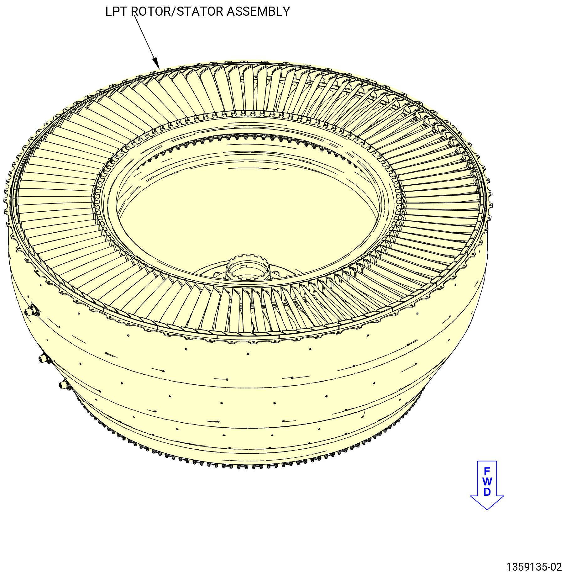
| LOW PRESSURE TURBINE ROTOR/STATOR ASSEMBLY - DISASSEMBLY 001 - CONFIGURATION 02 | ||
| GENX-1B ENGINE MANUAL | Dated: 01/30/2025 | |
| EM 72-56-00 , DISASSEMBLY 001 | ||
| LOW PRESSURE TURBINE ROTOR/STATOR ASSEMBLY - DISASSEMBLY 001 - CONFIGURATION 02 | ||
| * * * FOR ALL |
| TASK 72-56-00-040-802 |
| 1 . | General. |
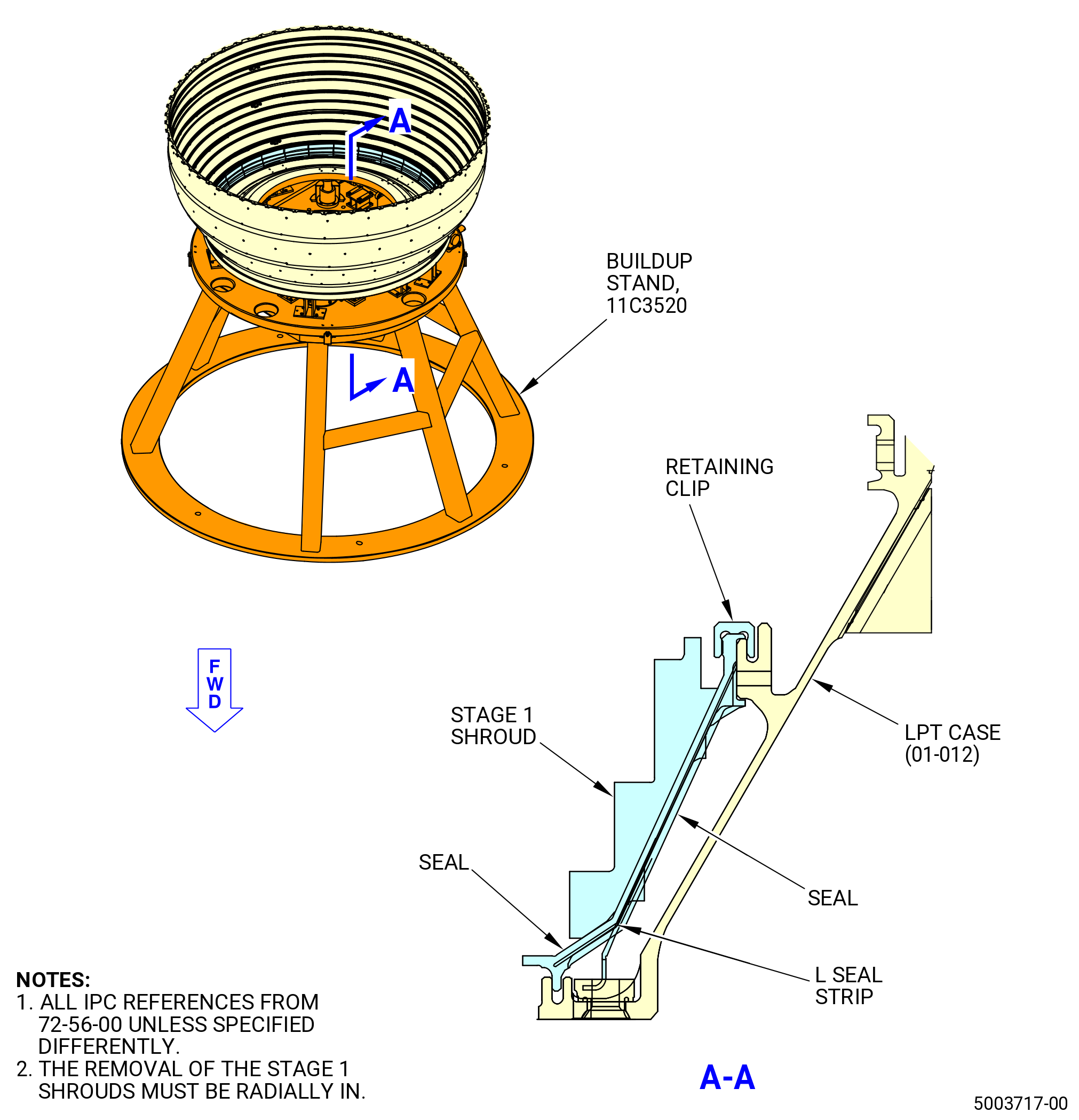
| A. | This procedure gives instructions to disassemble the low pressure turbine (LPT) rotor/stator assembly (01-010A , 72-00-04) (SIN 93000) for engines that were affected by SB 72-0040. Refer to Figure 501. |
| NOTE: |
|
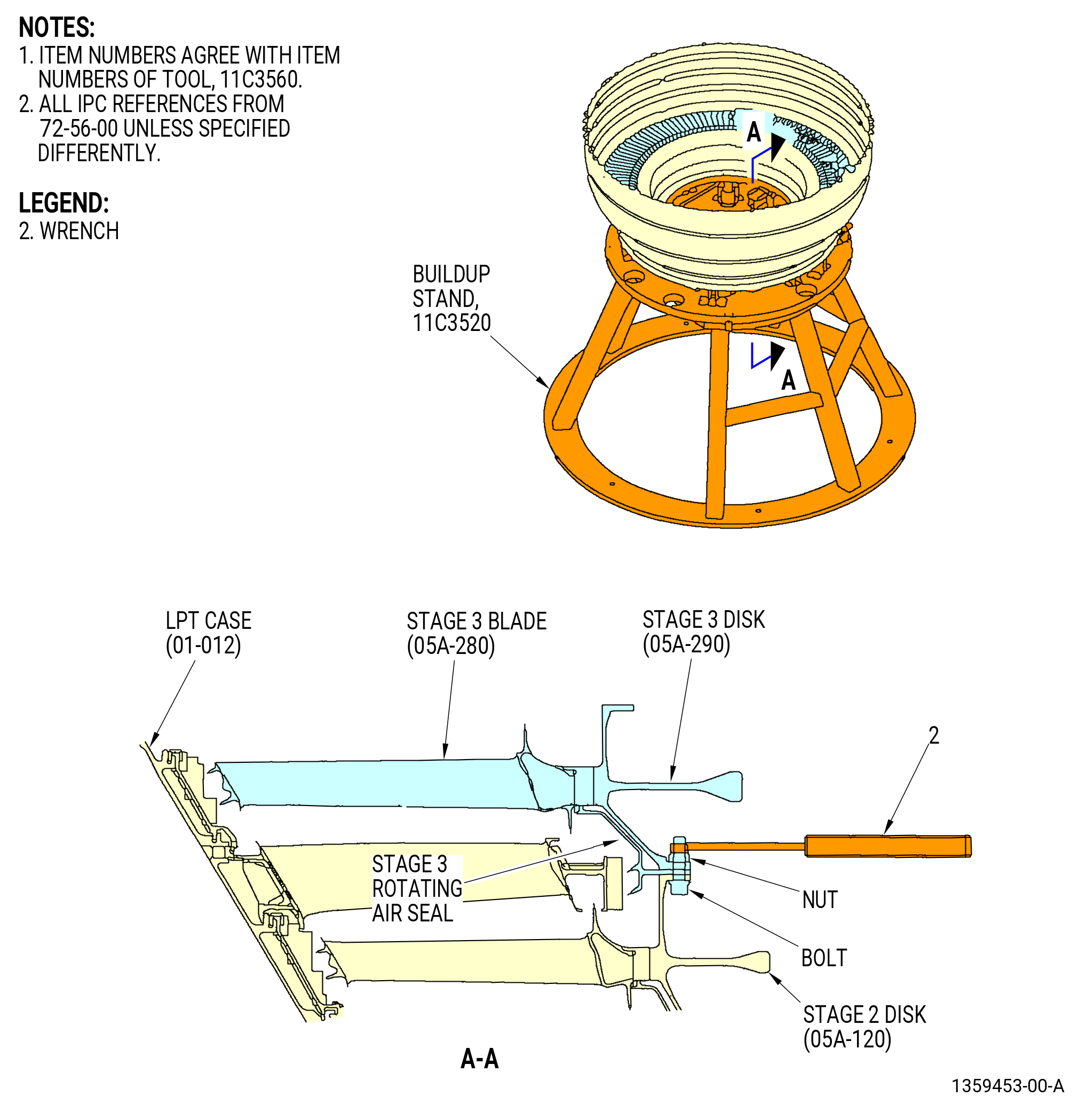
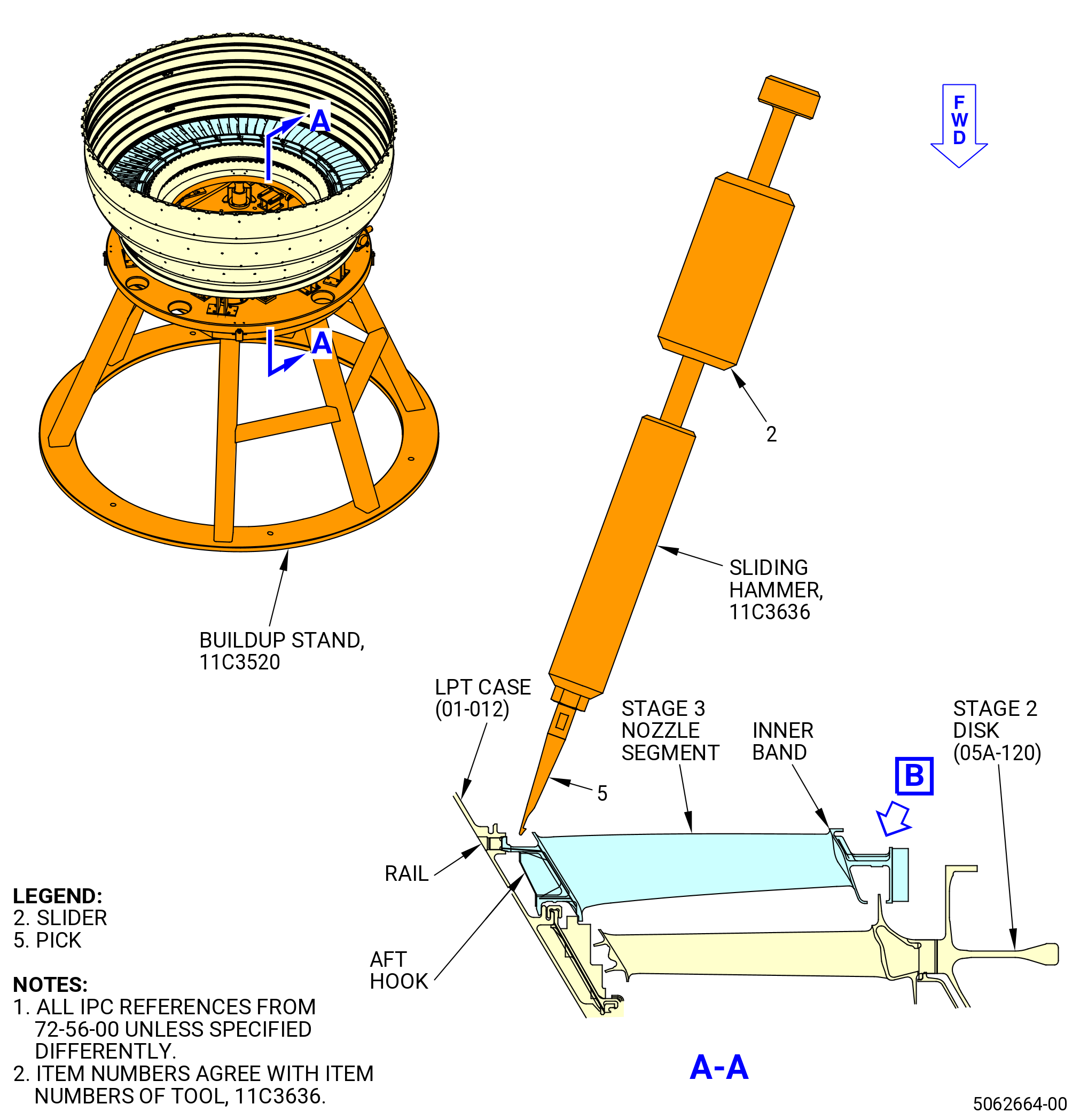
| B. | The LPT rotor/stator assembly is installed on the 11C3520 buildup stand. |
| C. | If an axisymmetric rotating part with a visible crack through the axial or radial thickness of the part feature is found during the disassembly procedure, then the mating Life Limited Part(s) (LLP) can be affected. The mating LLP must be considered not serviceable and not repairable. |
| NOTE: |
|
| NOTE: |
|
| 2 . | Tools, Equipment, and Materials. |
| NOTE: |
|
| A. | Tools and Equipment. |
| (1) | Special Tools. |
| (2) | Standard Tools and Equipment. |
|
| (3) | Locally Manufactured Tools. |
| B. | Consumable Materials. None. |
| C. | Referenced Procedures. None. |
| D. | Expendable Parts. None. |
| 3 . | Procedure. |
| Subtask 72-56-00-040-114 |
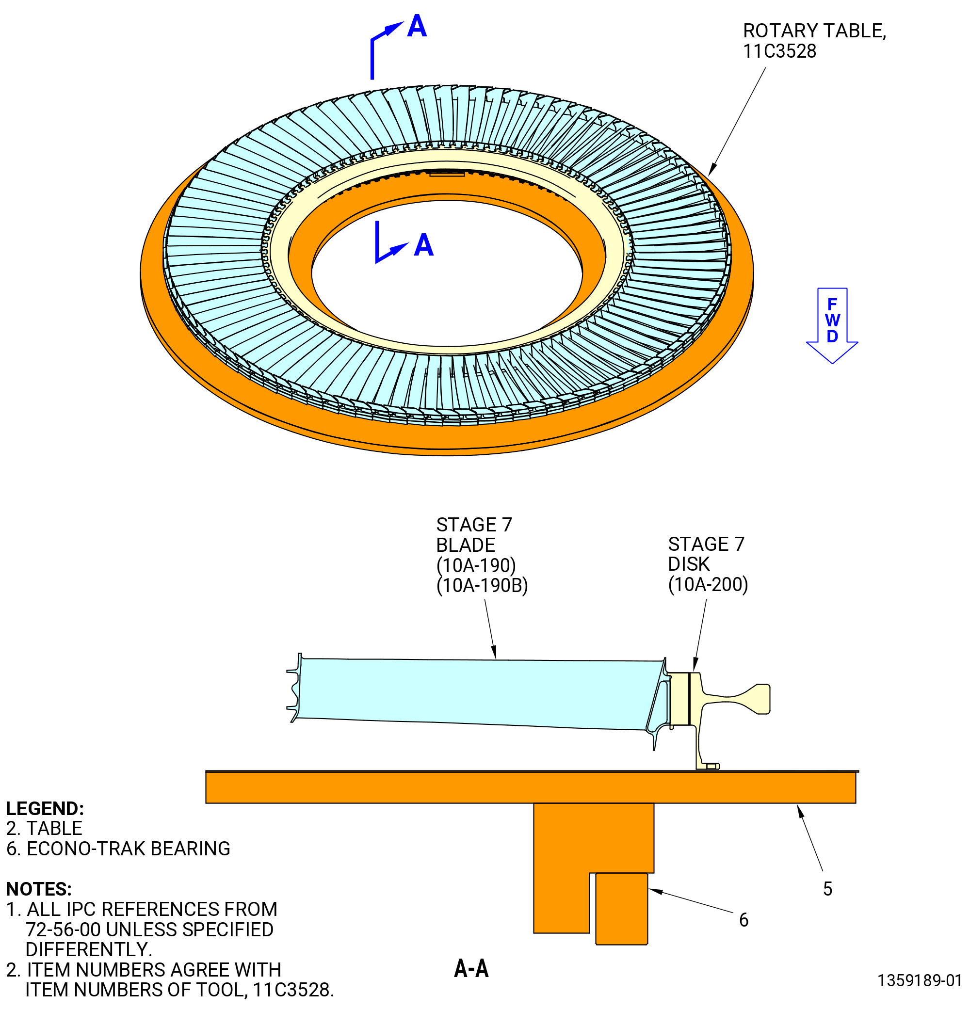
| A. | Remove the stage 7 disk (10A-200) and blade assembly and the stage 7 rotating air seal from the LPT case (01-012) as follows. |
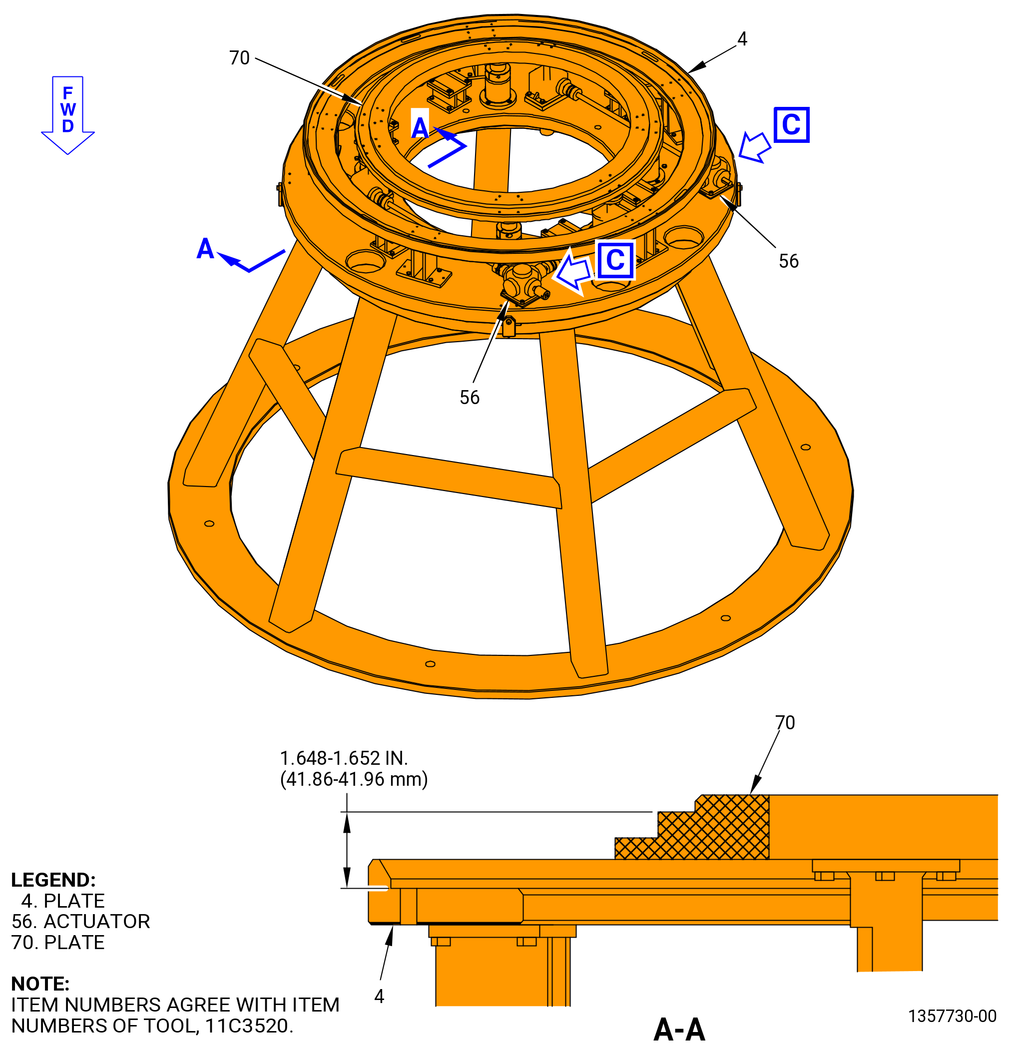
| (1) | Make sure the 11C3520 buildup stand plate (item 70) is at the NOMINAL position. Refer to Figure 502. |
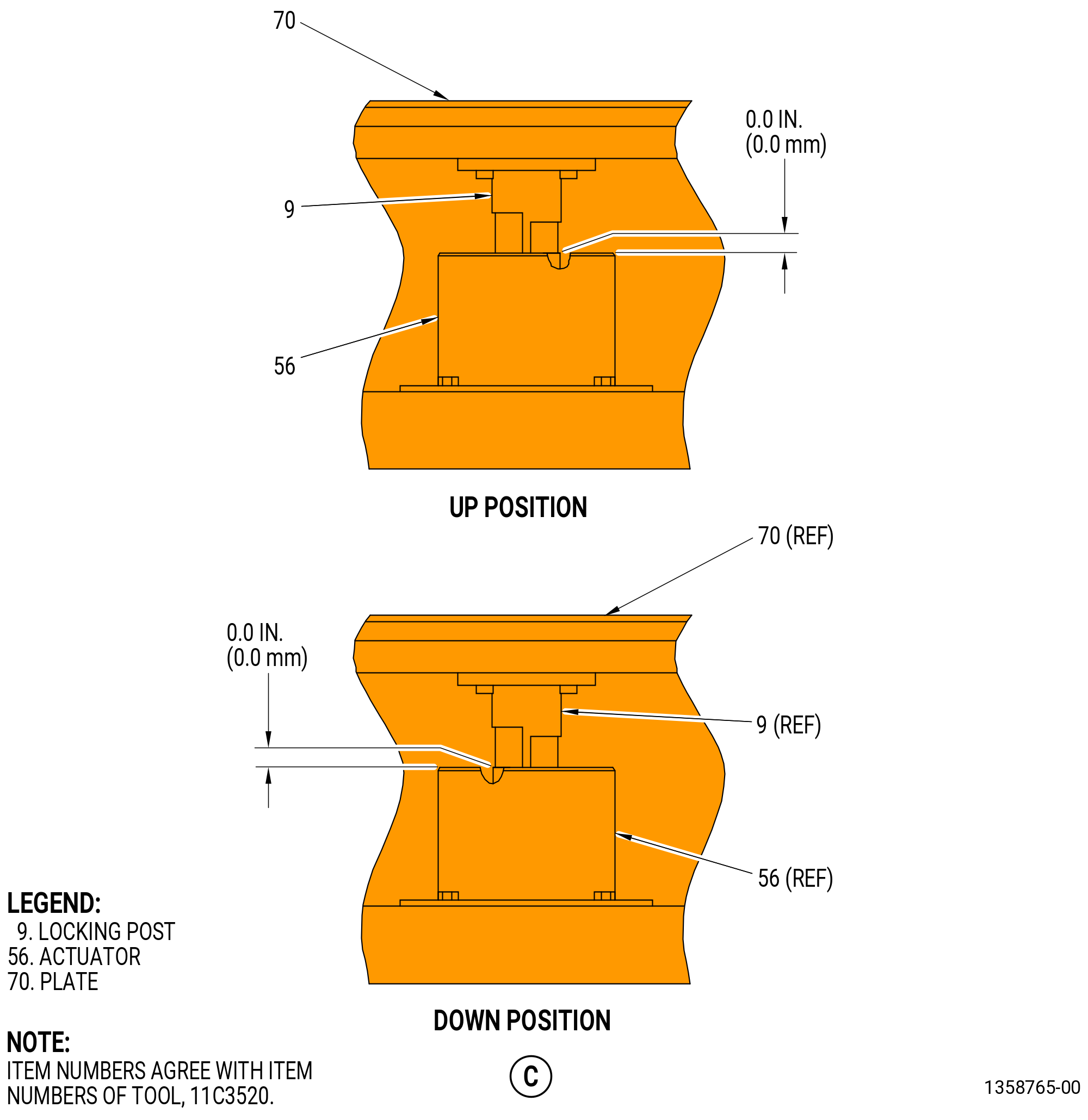
| (a) | If necessary, use the actuator (item 56) to adjust the plate (item 70) to the NOMINAL position. The slots of the locking post (item 9) shall be in the up position. |
| (b) | The height of the plate (item 70) shall be 1.601-1.605 inch (40.66-40.76 mm) from the plate (item 4). |
| CAUTION: |
|
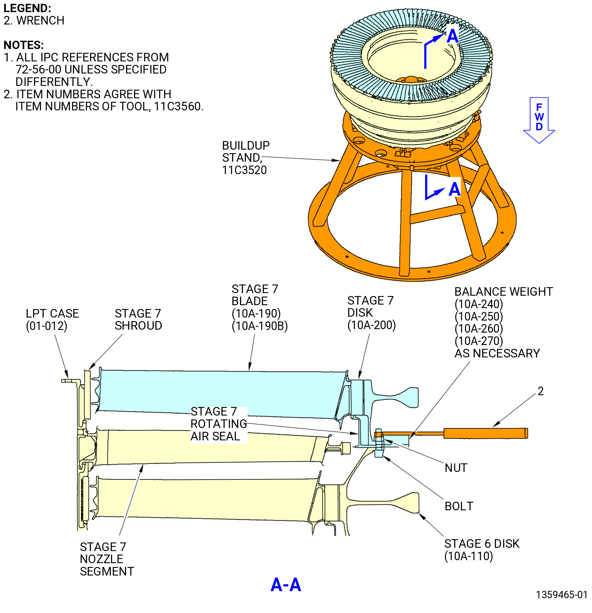
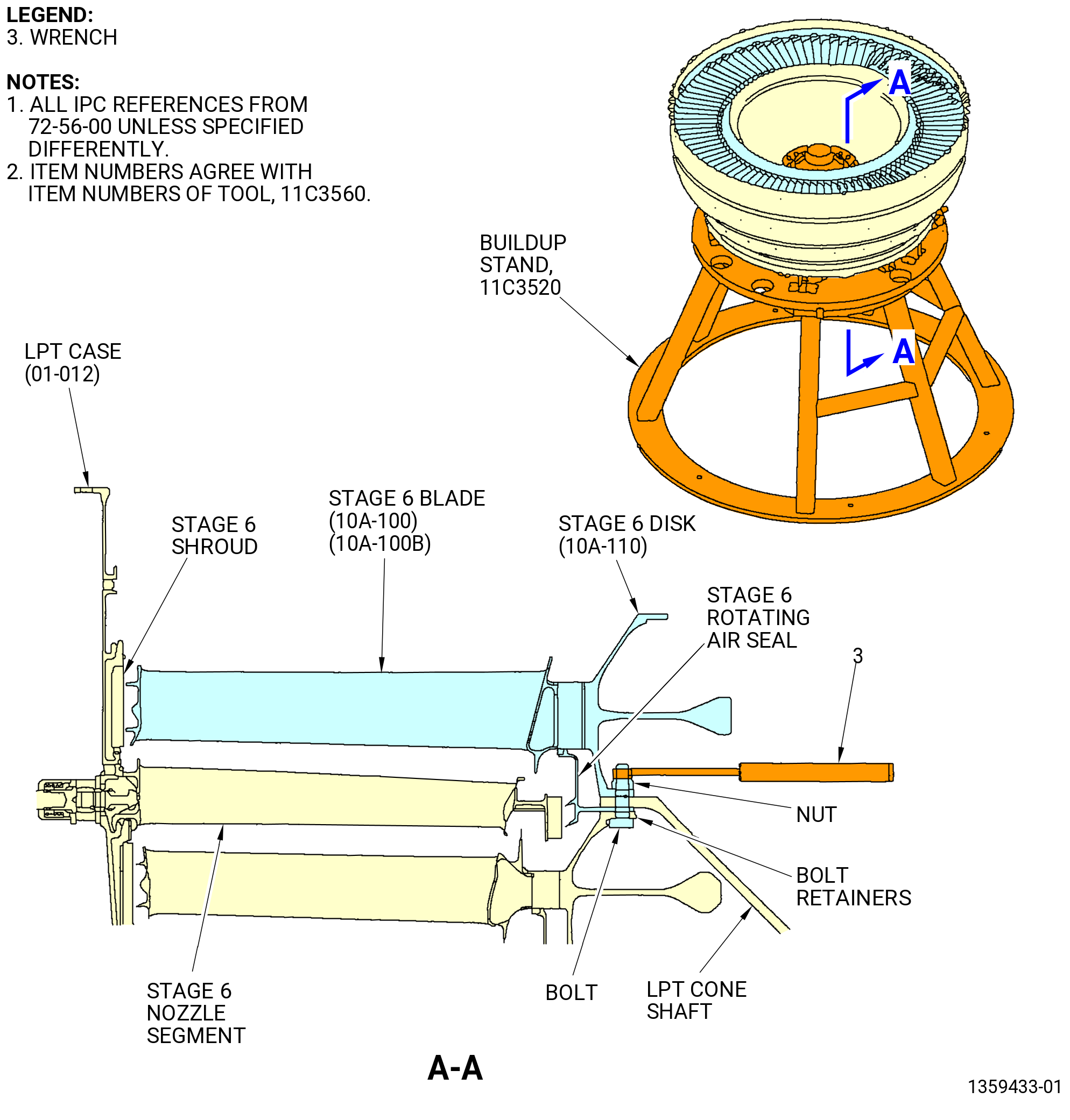
| (2) | Remove the nuts, bolts, and balance weights (10A-240, 10A-250, 10A-260, 10A-270) from the stage 6 disk, stage 7 rotating air seal, and stage 7 disk. Use the wrench (item 2) of the 11C3560 nut tighten wrench. Refer to Figure 503. |
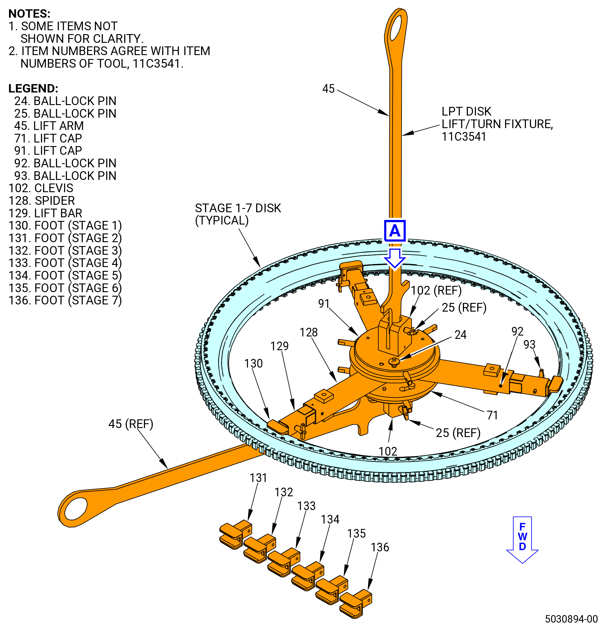
| (3) | Prepare the 11C3541 LPT disk lift/turn fixture to lift the stage 7 disk and blade assembly. Refer to Figure 504. |
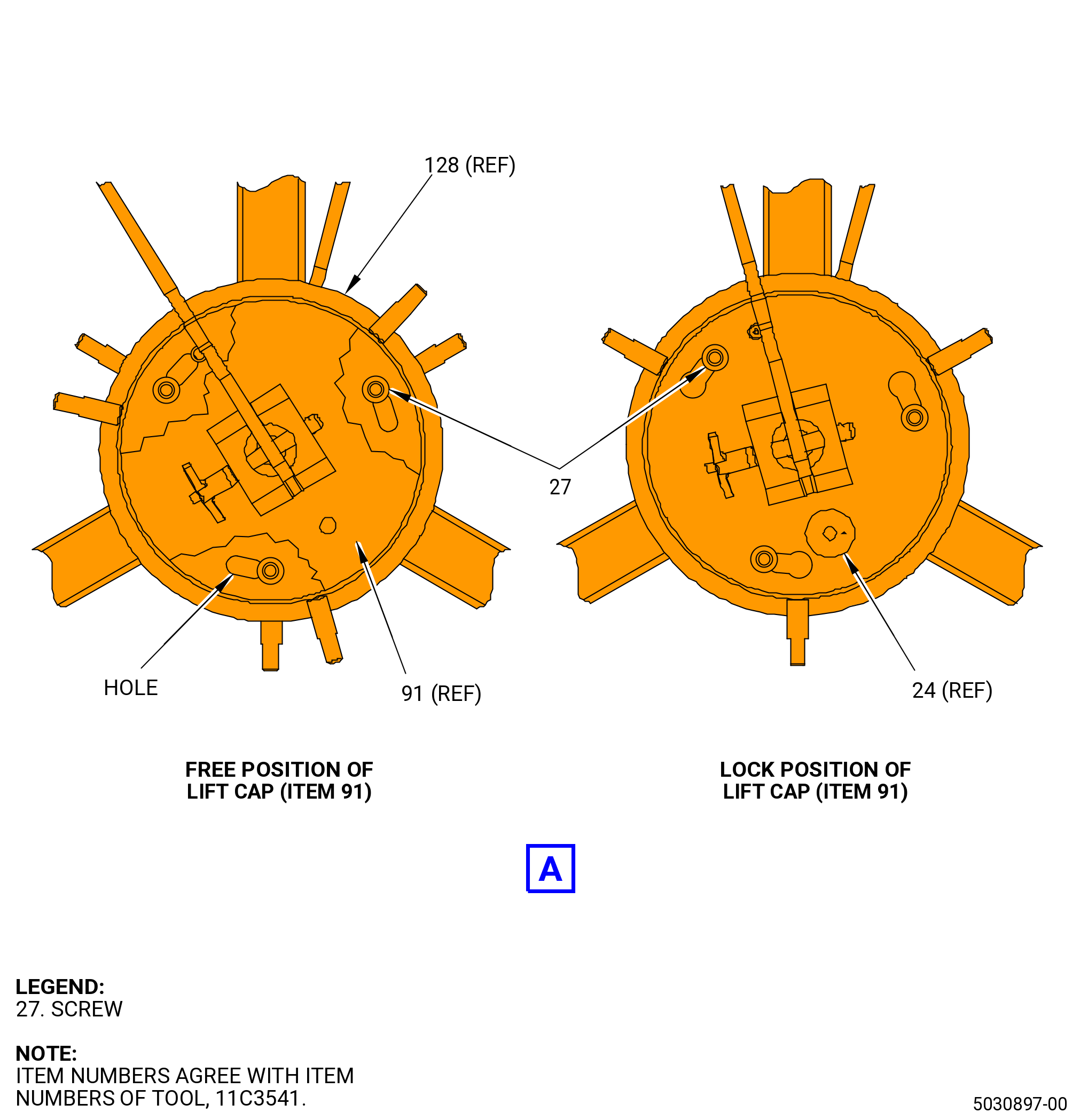
| (a) | Install the lift cap (item 91) on the spider (item 128). |
| 1 | Put the lift cap on the spider so the screws (item 27) go into the holes in the free positions of the spider. |
| 2 | Turn the lift cap CW until the pins are in the lock positions. |
| 3 | Insert the ball lock pin (item 24) to lock the lift cap to the spider. |
| (b) | Install the set of feet marked for stage 7 (item 136) into the lift bars (item 129) and insert the ball lock pins (item 93). |
| NOTE: |
|
| (c) | Install the bar/foot assemblies in the legs of the spider (item 128). |
| 1 | Insert two of three lift bars (item 129) in the legs of the spider. |
| 2 | Adjust the positions of the two lift bars (item 129) so the scribed lines for stage 7 align with the edges of the spider legs. |
| 3 | Insert the ball lock pins (item 92) to lock the lift bars to the spider. |
| 4 | Fully insert a third lift bar (item 129) into the third spider leg. |
| Subtask 72-56-00-040-115 |
| (4) | Install the 11C3541 LPT disk lift turn fixture on the stage 7 disk. Refer to Figure 504 and do as follows: |
| (a) | Install the lift arm (item 45) into the clevis (item 102) and insert the ball lock pin (item 25). |
| (b) | Attach a hoist to the lift arm (item 45). |
| WARNING: |
|
| CAUTION: |
|
| (c) | Carefully lift the 11C3541 LPT disk lift/turn fixture and lower it in the bore of the stage 7 disk. |
| (d) | Put the stage 7 foot (item 136) at two locations into the stage 7 disk. |
| (e) | Extend the third lift bar (item 129) that you inserted in the third spider leg. |
| 1 | Adjust the position of the lift bar (item 129) so the scribed line for stage 7 comes to the edge of the spider leg. |
| 2 | Lock the lift bar (item 129) in the spider (item 128) with the ball lock pins (item 92). |
| WARNING: |
|
| (5) | Lift the stage 7 disk and blade assembly from the LPT case (01-012) and put the assembly in a safe location. |
| (6) | Remove the 11C3541 LPT disk lift/turn fixture from the stage 7 disk and blade assembly. Refer to Figure 504 and do as follows: |
| (a) | Remove the ball lock pins (item 92) from the one of the three legs of the spider (item 128). |
| (b) | Retract the lift bar (item 129). |
| WARNING: |
|
| (c) | Lift the 11C3541 LPT disk lift/turn fixture from the stage 7 disk. |
| (7) | Remove the stage 7 rotating air seal from the stage 6 disk. Refer to Figure 503. |
| Subtask 72-56-00-040-116 |
| B. | Remove the stage 7 shrouds from the LPT case (01-012) as follows. Refer to Figure 503. |
| (1) | Move the aft ends of the stage 7 shrouds radially in to disengage the rail of the LPT case (01-012). |
| (2) | Remove the stage 7 shrouds. |
| Subtask 72-56-00-040-117 |
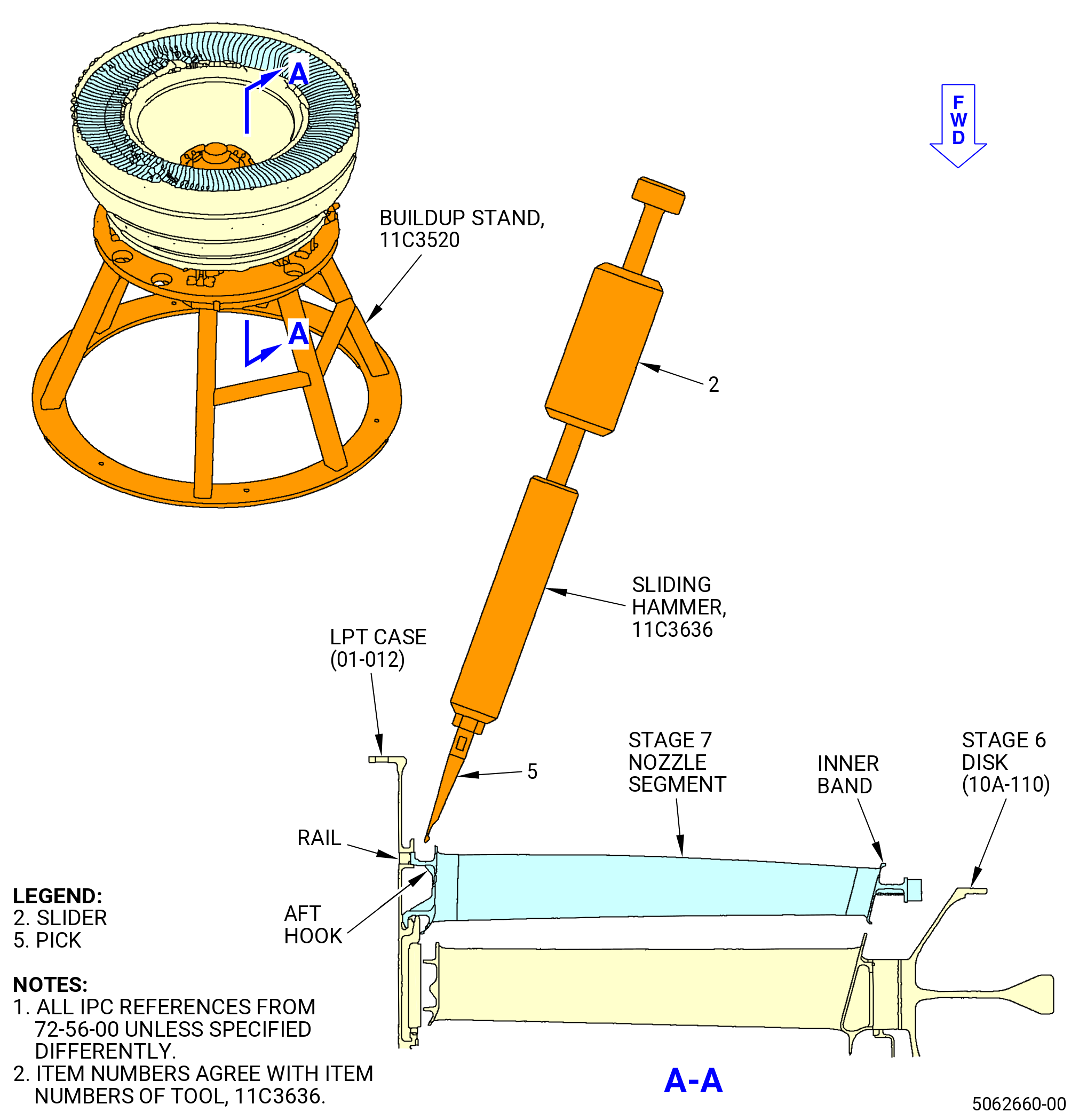
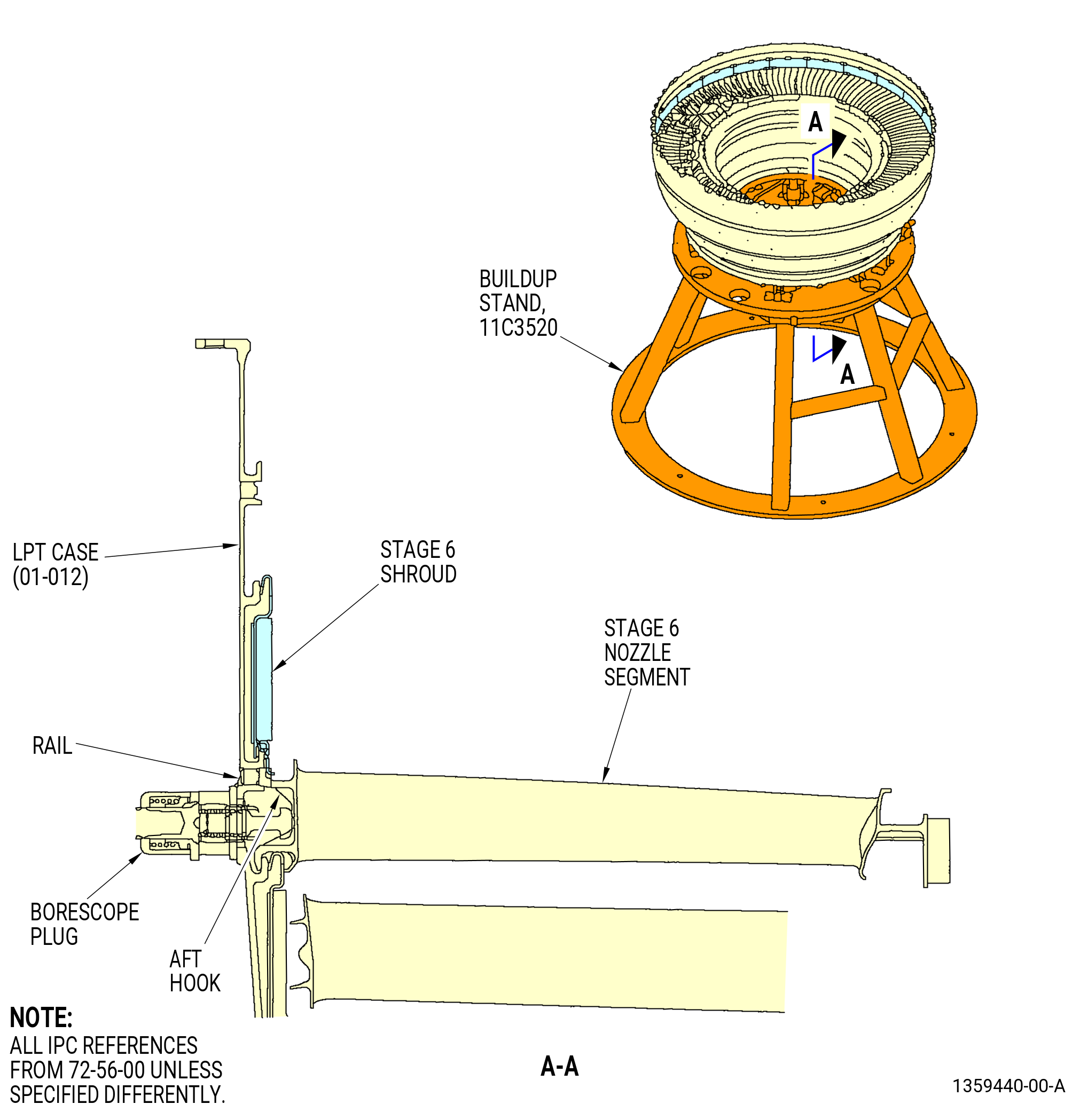
| C. | Remove the stage 7 nozzle segments from the LPT case (01-012) as follows. Refer to Figure 505. |
| (1) | Disengage the stage 7 nozzle segments from the rail of the LPT case (01-012) as follows: |
| (a) | Push down on the ends of adjacent stage 7 nozzle segments and move them aft to help with removal of the first nozzle segment. |
| (b) | Move the inboard end of the stage 7 nozzle segments forward on the 11C3520 buildup stand. |
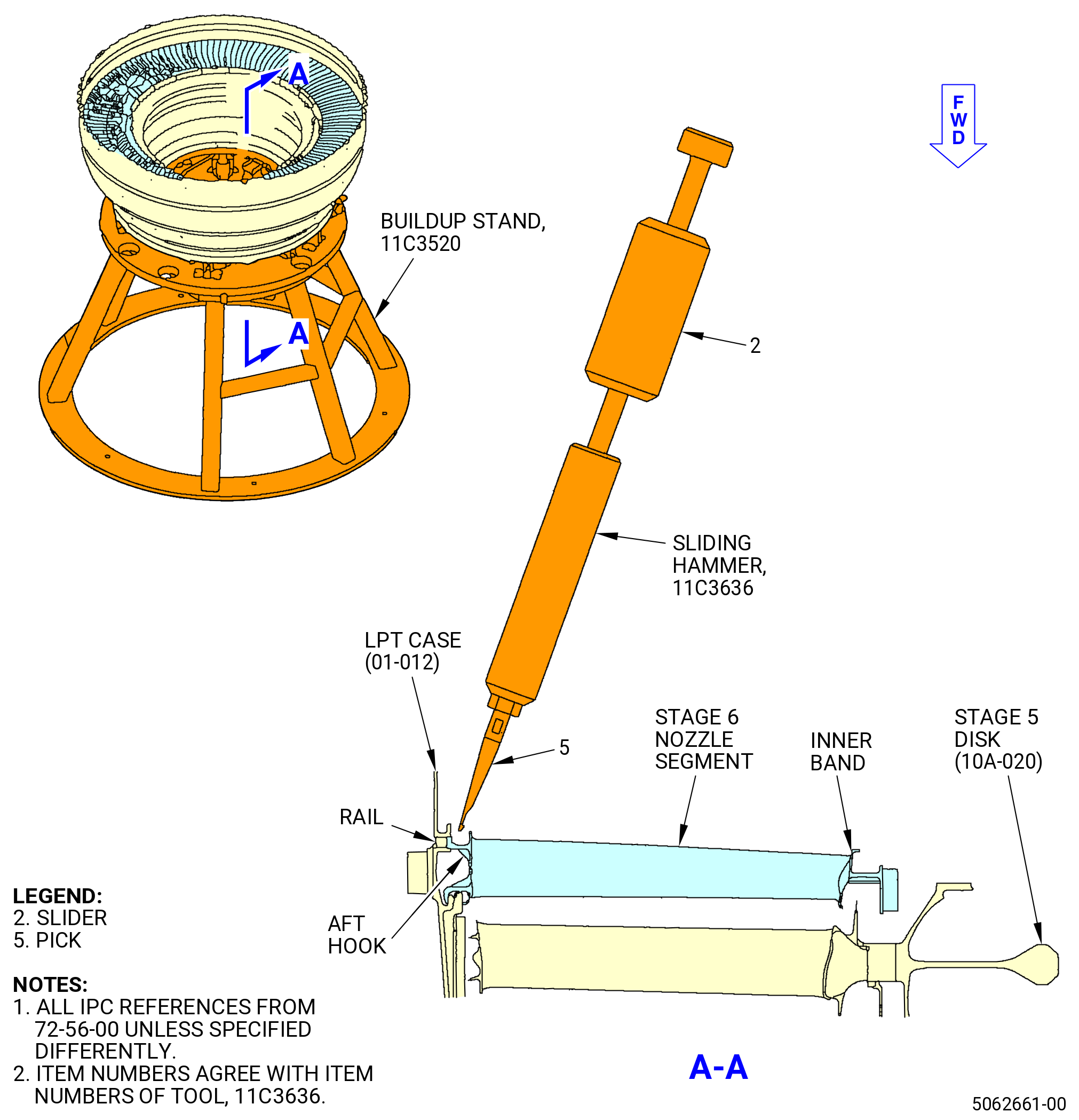
| (c) | If necessary, lightly tap the inner band aft lips of the stage 7 segments with a mallet. This will disengage the aft hook of the outer band from the rail of the LPT case (01-012). |
| (d) | Engage the pick (item 5) of the 11C3636 sliding hammer with the anti-rotation slot of the stage 7 nozzle segments. |
| (e) | Quickly move the slider (item 2) to disengage the stage 7 nozzle segments from the LPT case (01-012). |
| (2) | Remove the stage 7 nozzle segments. |
| (3) | Move the LPT rotors aft to the NOMINAL position on the 11C3520 buildup stand. Refer to Figure 502. |
| Subtask 72-56-00-040-118 |
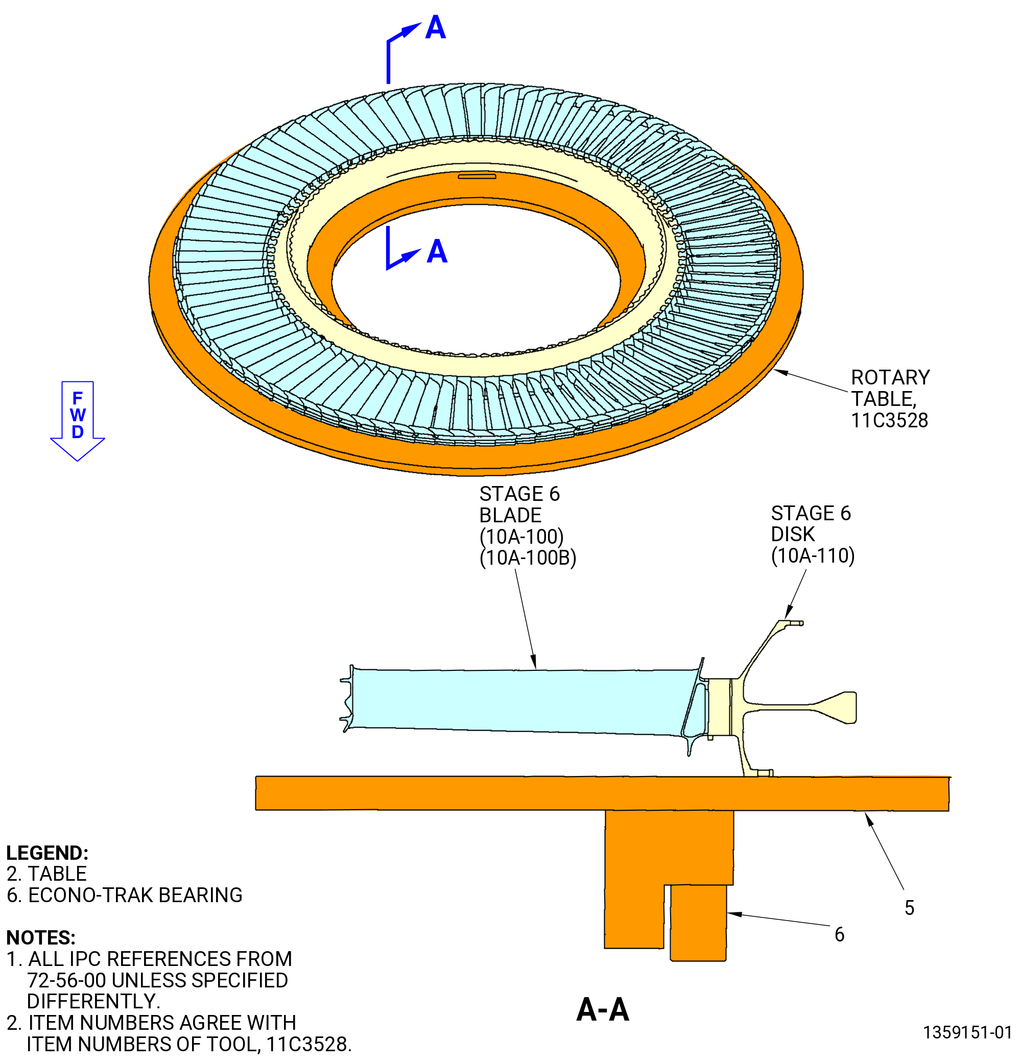
| D. | Remove the stage 6 disk (10A-110) and blade assembly from the LPT case (01-012) as follows: |
| CAUTION: |
|
| (1) | Remove the nuts, bolts, and bolt retainers that attach the stage 6 disk to the LPT cone shaft. Refer to Figure 506. |
| (2) | Prepare the 11C3541 LPT disk lift/turn fixture to lift the stage 6 disk and blade assembly. Refer to Figure 504 and do as follows: |
| (a) | Install the set of feet (item 135) marked for stage 6 into the lift bars (item 129) and attach with the ball-lock pins (item 93). |
| NOTE: |
|
| (b) | Install the bar/foot assemblies into the legs of the spider (item 128). |
| 1 | Adjust the positions of two of the lift bars (item 129) so the scribed lines for stage 6 align with the edges of the spider legs. |
| 2 | Insert the ball lock pins (item 92) to lock the two lift bars (item 129) to the spider. |
| 3 | Fully insert a third lift bar (item 129) into the third spider leg. |
| (3) | Install the 11C3541 LPT disk lift/turn fixture to the stage 6 disk as follows: |
| (a) | Install the lift arm (item 45) into the clevis (item 102) and insert the ball lock pin (item 25). |
| (b) | Attach a hoist to the lift arm (item 45). |
| WARNING: |
|
| CAUTION: |
|
| (c) | Carefully lift the 11C3541 LPT disk lift/turn fixture and lower it into the bore of the stage 6 disk. |
| (d) | Put the stage 6 foot (item 135) at two locations into the stage 6 disk. |
| (e) | Extend the third lift bar (item 129) that you inserted in the third spider leg and engage into the stage 6 disk as follows: |
| 1 | Adjust the position of the lift bar (item 129) so the scribed line for stage 6 aligns with the edge of the spider leg. |
| 2 | Lock the lift bar (item 129) in the spider (item 128) with the ball lock pins (item 92). |
| WARNING: |
|
| (4) | Lift the stage 6 disk and blade assembly from the LPT case (01-012) and put the assembly in a safe location. Refer to Figure 506. |
| (5) | Remove the 11C3541 LPT disk lift/turn fixture from the stage 6 disk and blade assembly. Refer to Figure 504 and do as follows: |
| (a) | Remove the ball lock pins (item 92) from one of the three legs of the spider (item 128). |
| (b) | Retract the lift bar (item 129). |
| WARNING: |
|
| (c) | Lift the 11C3541 LPT disk lift/turn fixture from the stage 6 disk. |
| Subtask 72-56-00-040-119 |
| E. | Remove the LPT cone shaft and the stage 6 rotating air seal from the LPT case (01-012) as follows. Refer to Figure 506 and Figure 507. |
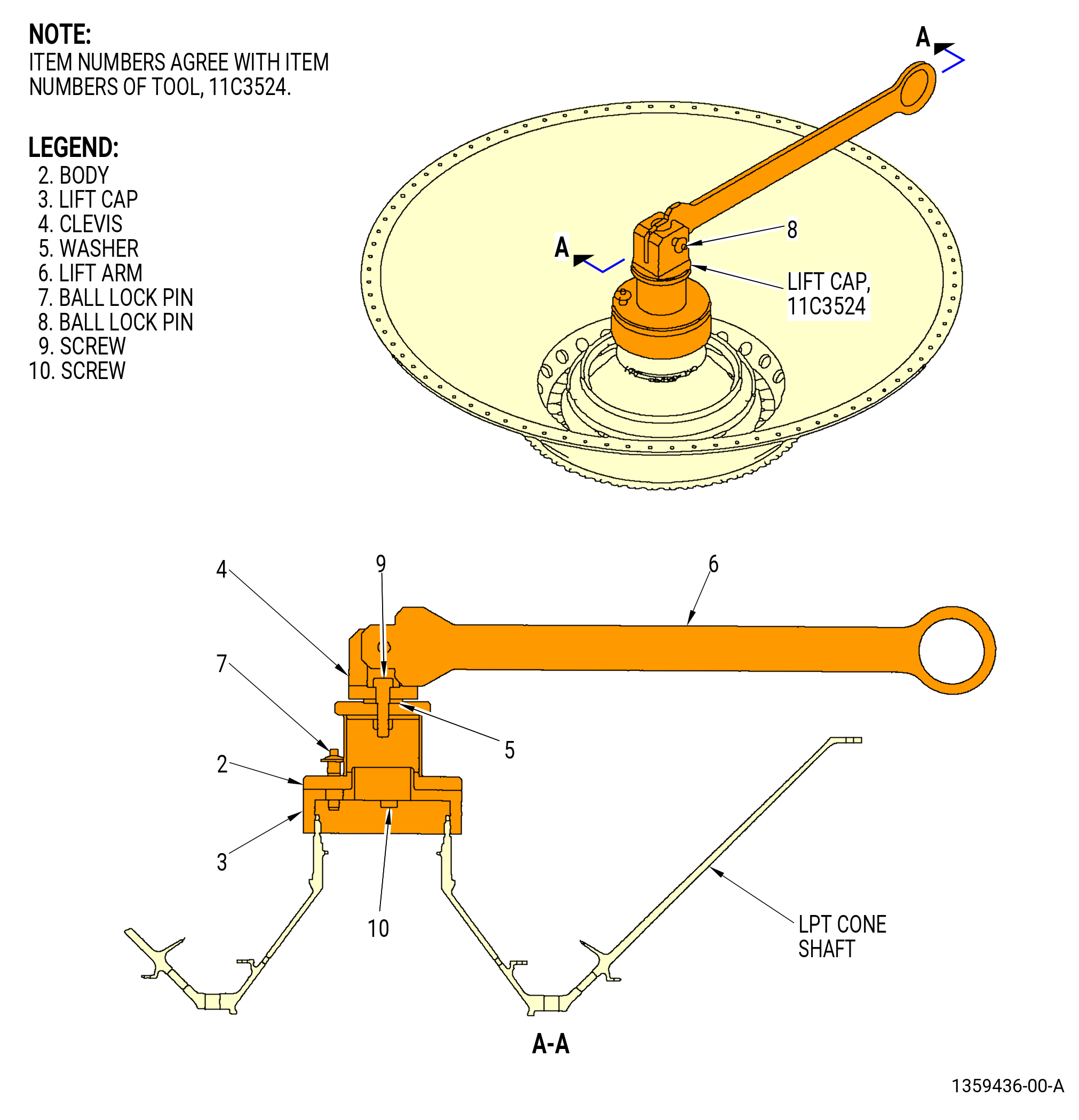
| (1) | Install the 11C3524 lift cap on the LPT cone shaft until it is tight. Refer to Figure 508. |
| (a) | Turn the lift cap (item 3) CW on the aft threads of the LPT cone shaft until it is tight. |
| (b) | Put the body (item 2) on the lift cap (item 3) so the three screws (item 10) go in the ellipse holes in the free positions of the lift cap. |
| (c) | Turn the body (item 2) on to the lift cap (item 3) CW until the screws (item 10) come to the lock positions. |
| (d) | Install the ball lock pin (item 7) to lock the body (item 2) to the lift cap (item 3) |
| (e) | Install the clevis (item 4) and the washer (item 5) to the body (item 2) to the lift cap (item 3). |
| (f) | Install the lift arm (item 6) to the clevis (item 4) and insert the ball lock pin (item 8). |
| (2) | Attach a hoist to the lift arm (item 6) to the clevis (item 4) and insert the ball lock pin (item 8). |
| WARNING: |
|
| (3) | Lift the LPT cone shaft from the LPT case (01-012). |
| CAUTION: |
|
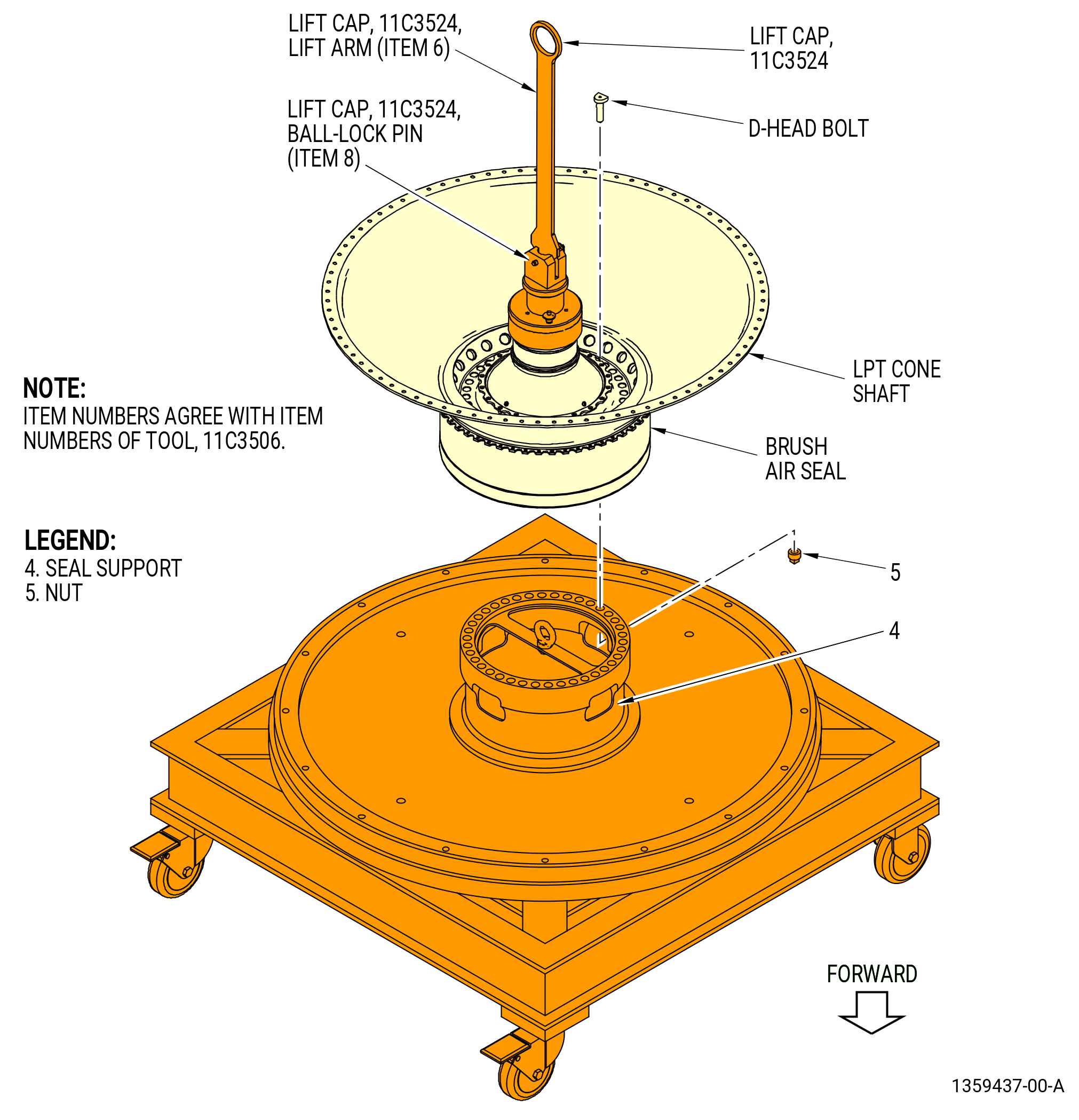
| (4) | Put the LPT cone shaft, forward end down, onto the 11C3506 buildup/transport/storage stand as follows. Refer to Figure 509. |
| (a) | Lower the LPT cone shaft onto the seal support (item 4). |
| (b) | Align the holes of the seal support (item 4) to the D-head bolts and put the mid forward flange onto the seal support. |
| (c) | Attach the LPT cone shaft to the seal support (item 4) with nut (item 5) at four locations. |
| (5) | Remove the hoist from the lift arm (item 6) of the 11C3524 lift cap. |
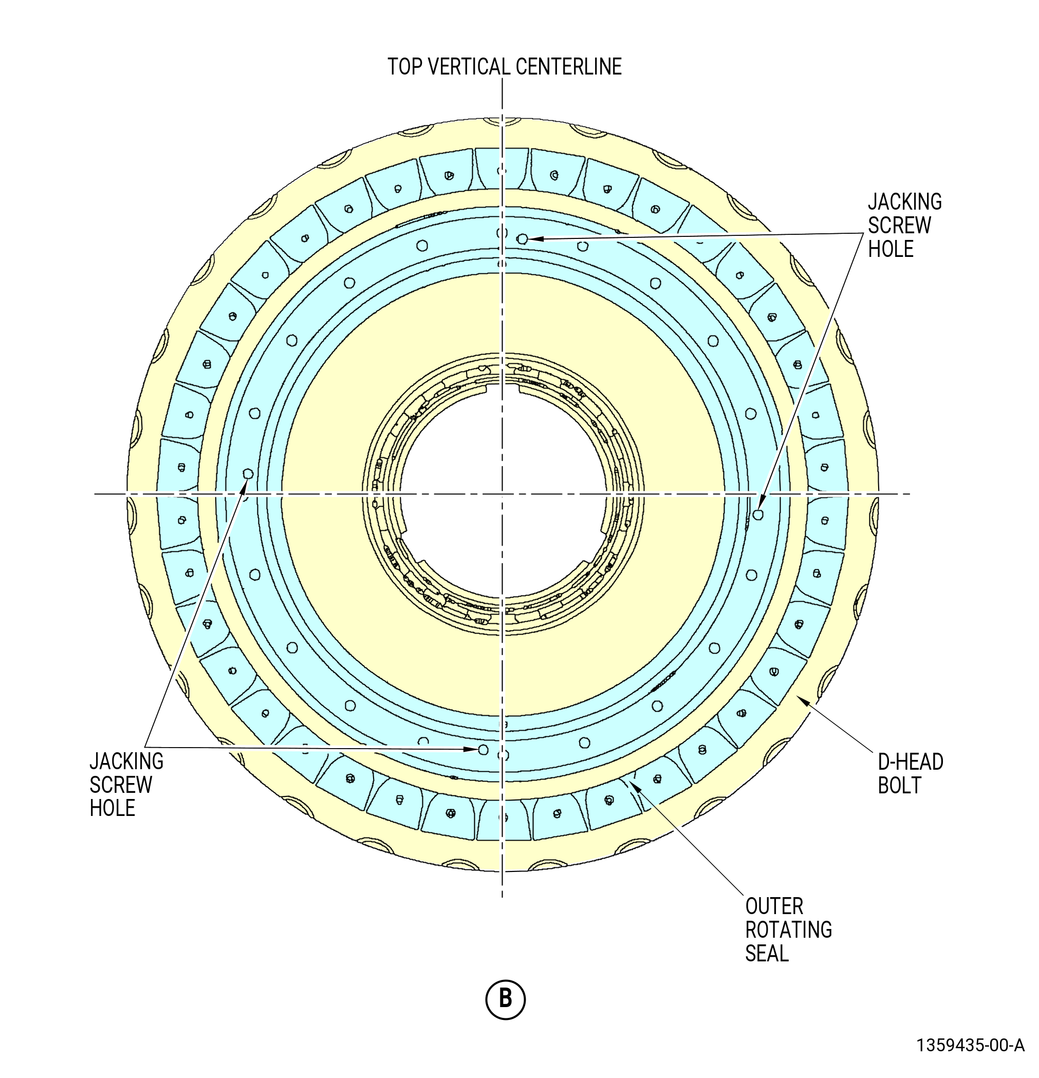
| (6) | Remove the bolts from the outer rotating seal. |
| (7) | Remove the outer rotating seal from the LPT cone shaft. If necessary, remove the outer rotating seal with four jacking screws (0.250-28 UNF-2A). Refer to Figure 507. |
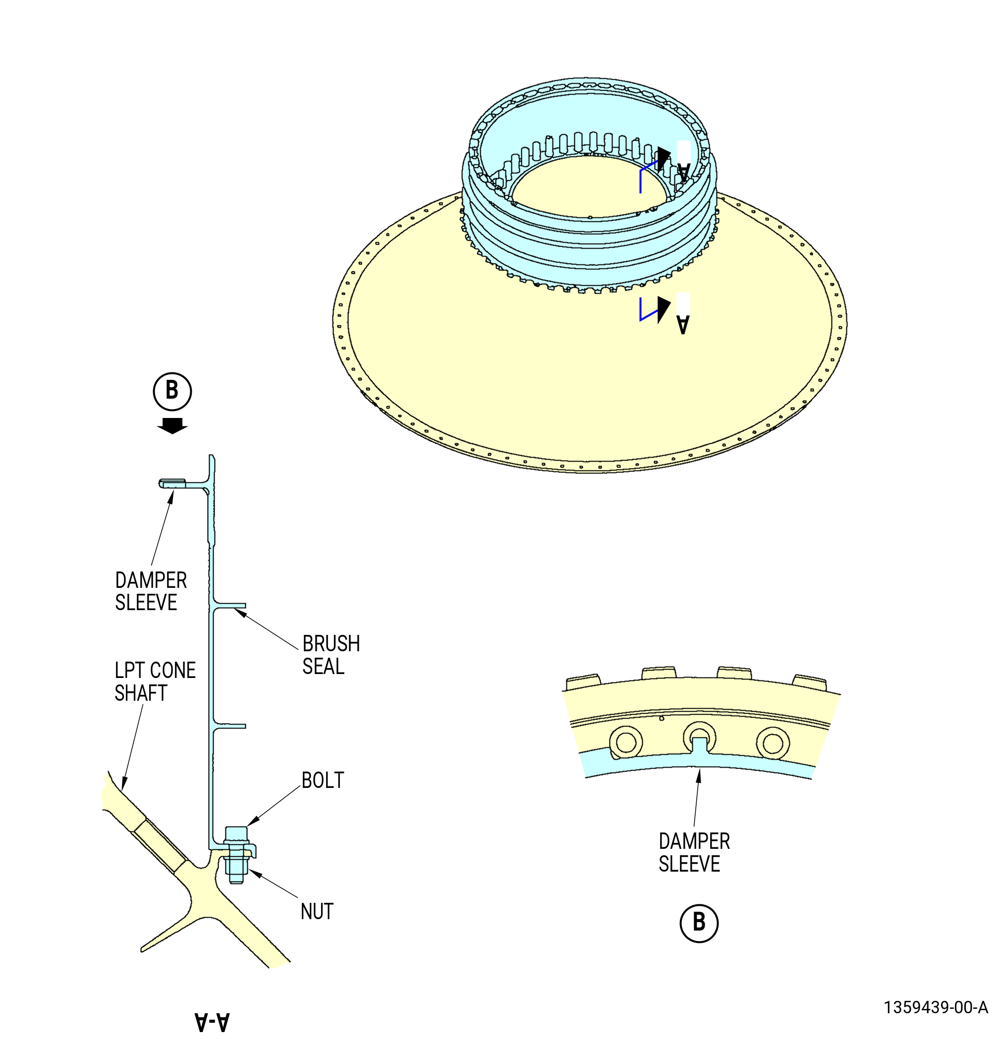
| (8) | Remove the brush air seal from the LPT cone shaft as follows. Refer to Figure 507 and Figure 511. |
| (a) | Remove the nuts and bolts. |
| (b) | Remove the brush air seal from the LPT cone shaft and carefully place onto the 11C3506 buildup/transport/storage stand as follows: |
| 1 | If necessary, deflect the damper seal locating tabs from locating holes while moving the air brush seal aft and away from the flange to allow the removal of the damper sleeve. |
| 2 | Carefully lower the air brush seal onto the 11C3506 buildup/transport/storage stand. |
| (9) | Remove the nuts (item 5) at four locations from the D-head bolts. |
| (10) | Remove the D-head bolts from the LPT cone shaft. |
| (11) | Attach a hoist to the lift arm (item 6) of the 11C3524 lift cap. |
| WARNING: |
|
| (12) | Carefully lift the LPT cone shaft from the 11C3506 buildup/transport/storage stand. |
| (13) | Remove the brush air seal from the buildup/transport/storage stand. |
| (14) | Remove the damper sleeve from the brush air seal. |
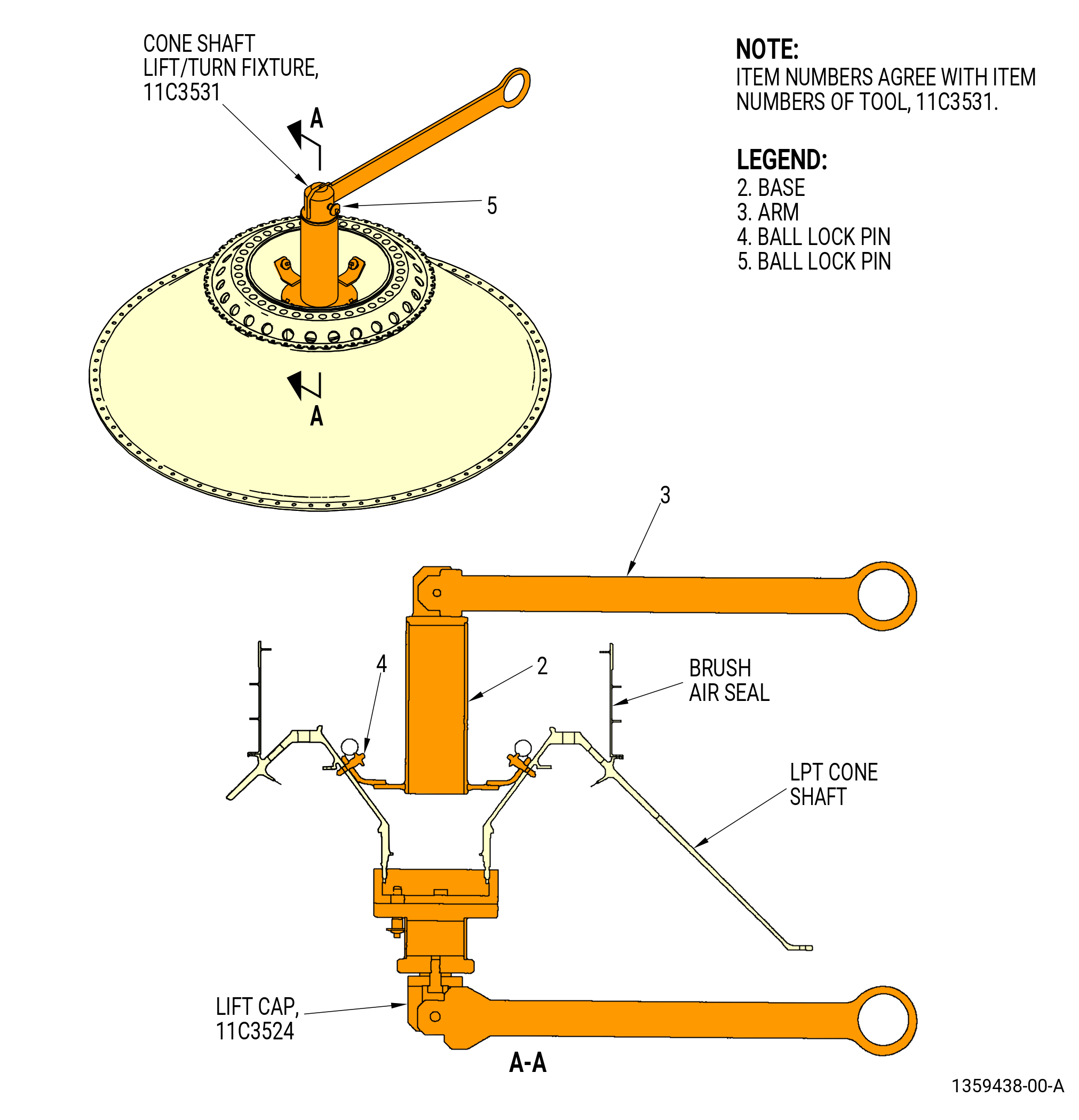
| (15) | Install the 11C3531 cone shaft lift/turn fixture to the LPT cone shaft as follows. Refer to Figure 510. |
| (a) | Install the base (item 2) to the forward side of the LPT cone shaft. |
| (b) | Secure the base to the LPT cone shaft with the ball rock pins (item 4). |
| (c) | Attach the arm (item 3) to the base (item 2) with the ball rock pin (item 5). |
| (16) | Attach a hoist to the arm (item 3). |
| WARNING: |
|
| (17) | Lift the forward side of the LPT cone shaft and lower the aft side of the LPT cone shaft at the same time. This will turn over the LPT cone shaft, aft side down. Lift until the load is supported by the 11C3531 cone shaft lift/turn fixture. |
| (18) | Remove the hoist from the lift arm (item 6) of the 11C3524 lift cap. Refer to Figure 508. |
| (19) | Remove the 11C3524 lift cap from the LPT cone shaft as follows: |
| (a) | Pull the pin (item 8) out and remove the lift arm (item 6) from the clevis (item 4). |
| (b) | Pull the ball lock pin (item 7) out and remove the body (item 2) from the lift cap (item 3). |
| (c) | Remove the lift cap (item 3) from the LPT cone shaft. |
| (20) | Put the LPT cone shaft, aft side down, on a worktable. Refer to Figure 510. |
| (21) | Remove the 11C3531 cone shaft lift/turn fixture from the LPT cone shaft. |
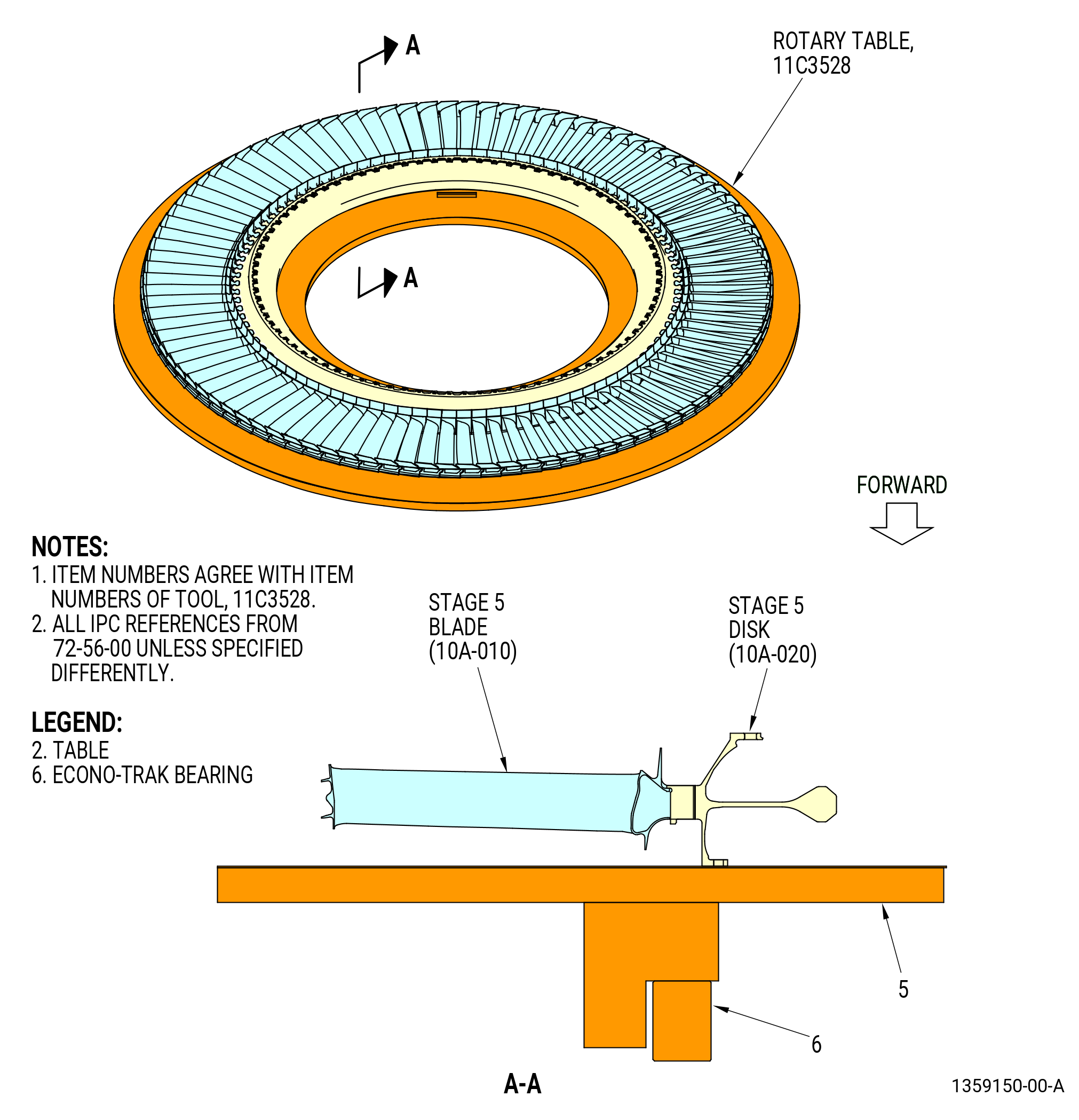
| (22) | Remove the stage 6 rotating air seal from the stage 5 disk (10A-020). |
| Subtask 72-56-00-040-120 |
| F. | Remove the stage 6 shrouds from the LPT case (01-012) as follows. Refer to Figure 512. |
| (1) | Move the aft ends of the stage 6 shrouds radially in to disengage the rail of the LPT case (01-012). |
| (2) | Remove the stage 6 shrouds. |
| Subtask 72-56-00-040-121 |
| G. | Remove the stage 6 nozzle segments from the LPT case (01-012) as follows. Refer to Figure 513. |
| (1) | Remove the borescope plug from the LPT case (01-012) and the stage 6 nozzle segment at the 9:30 o'clock position. Refer to Figure 512. |
| (2) | Disengage the stage 6 nozzle segments from the rail of the LPT case (01-012). |
| (a) | Move the inboard end of the stage 6 nozzle segments forward on the 11C3520 buildup stand. Refer to Figure 502. |
| (b) | If necessary, lightly tap the inner band aft lips of the stage 6 segments with a mallet. This will disengage the aft hook of the outer band from the rail of the LPT case (01-012). |
| (c) | Engage the pick (item 5) of the 11C3636 sliding hammer with the anti-rotation slot of the stage 6 nozzle segments. |
| (d) | Rapidly move the slider (item 2) to disengage the stage 6 nozzle segments from the LPT case (01-012). |
| (3) | Remove the stage 6 nozzle segments. |
| (4) | Adjust the height of the LPT rotors aft to the NOMINAL position on the 11C3520 buildup stand. Refer to Figure 502. |
| Subtask 72-56-00-040-122 |
| H. | Remove the stage 5 disk (10A-020) and blade assembly and the stage 5 rotating air seal from the LPT case (01-012) as follows: |
| CAUTION: |
|
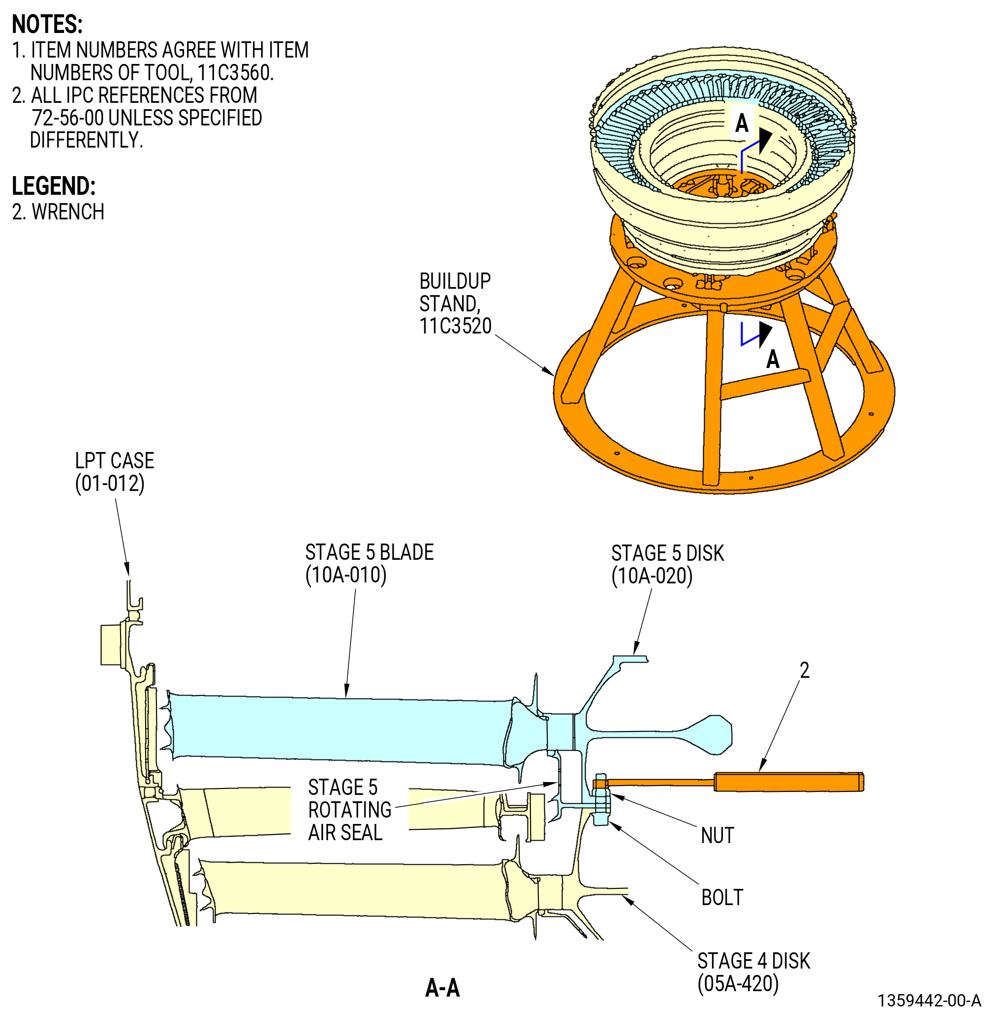
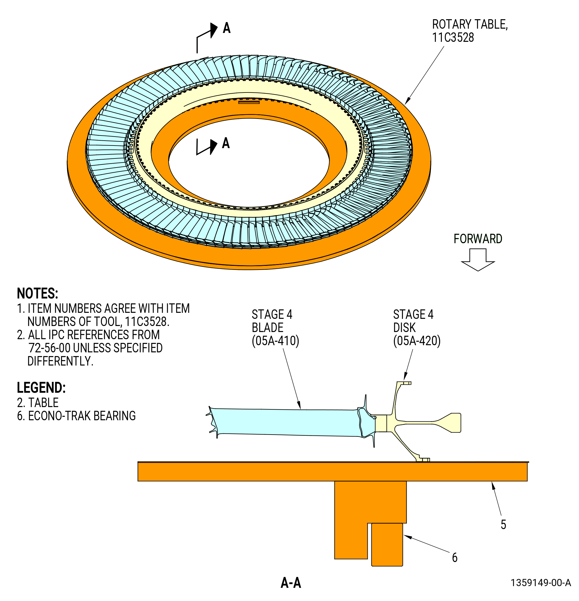
| (1) | Remove the nuts and bolts from the stage 4 disk (05A-420), the stage 5 rotating air seal, and the stage 5 disk. Refer to Figure 514. |
| (2) | Prepare the 11C3541 LPT disk lift/turn fixture to lift the stage 5 disk and blade assembly. Refer to Figure 504 and do as follows: |
| (a) | Install the set of feet marked for stage 5 (item 134) into the lift bars (item 129) and insert the ball lock pins (item 93). |
| NOTE: |
|
| (b) | Install the bar/foot assemblies into the legs of the spider (item 128). |
| 1 | Adjust the positions of two of the lift bars (item 129) so the scribed lines for stage 5 align with the edges of the spider legs. |
| 2 | Insert the ball lock pins (item 92) to lock the two lift bars (item 129) to the spider. |
| 3 | Fully insert a third lift bar (item 129) into the third spider leg. |
| (3) | Install the 11C3541 LPT disk lift/turn fixture LPT disk lift/turn fixture to the stage 5 disk as follows: |
| (a) | Install the lift arm (item 45) into the clevis (item 102) and insert the ball lock pin (item 25). |
| (b) | Attach an overhead hoist to the lift arm (item 45). |
| WARNING: |
|
| CAUTION: |
|
| (c) | Carefully lift the 11C3541 LPT disk lift/turn fixture and lower it in the bore of the stage 5 disk. |
| (d) | Extend the third lift bar (item 129) that you inserted in the third spider leg. |
| 1 | Adjust the position of the lift bar (item 129) so the scribed line for stage 5 aligns with the edge of the spider leg. |
| 2 | Lock the lift bar (item 129) in the spider (item 128) with the ball lock pins (item 92). |
| WARNING: |
|
| (4) | Lift the stage 5 disk and blade assembly from the LPT case (01-012) and put the assembly in a safe location. Refer to Figure 514. |
| (5) | Remove the 11C3541 LPT disk lift/turn fixture from the stage 5 disk and blade assembly. Refer to Figure 504 and do as follows: |
| (a) | Remove the ball lock pins (item 92) from one of the three legs of the spider (item 128). |
| (b) | Retract the lift bar (item 129). |
| WARNING: |
|
| (c) | Lift the 11C3541 LPT disk lift/turn fixture from the stage 5 disk. |
| (6) | Remove the stage 5 rotating air seal from the stage 4 disk. Refer to Figure 514. |
| Subtask 72-56-00-040-123 |
| I. | Remove the stage 5 shrouds from the LPT case (01-012) as follows. Refer to Figure 515. |
| (1) | Move the aft ends of the stage 5 shrouds radially in to disengage the rail of the LPT case (01-012). |
| (2) | Remove the stage 5 shrouds. |
| Subtask 72-56-00-040-124 |
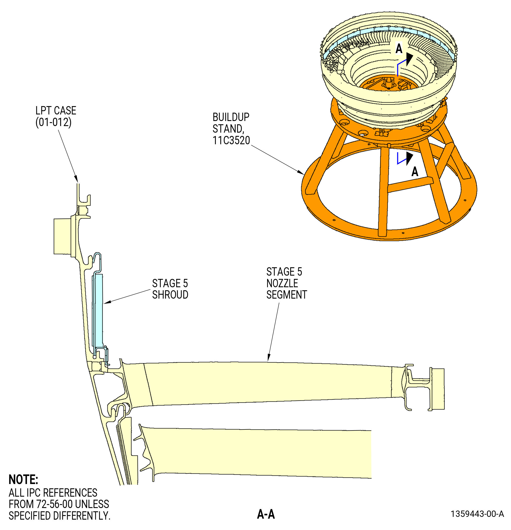
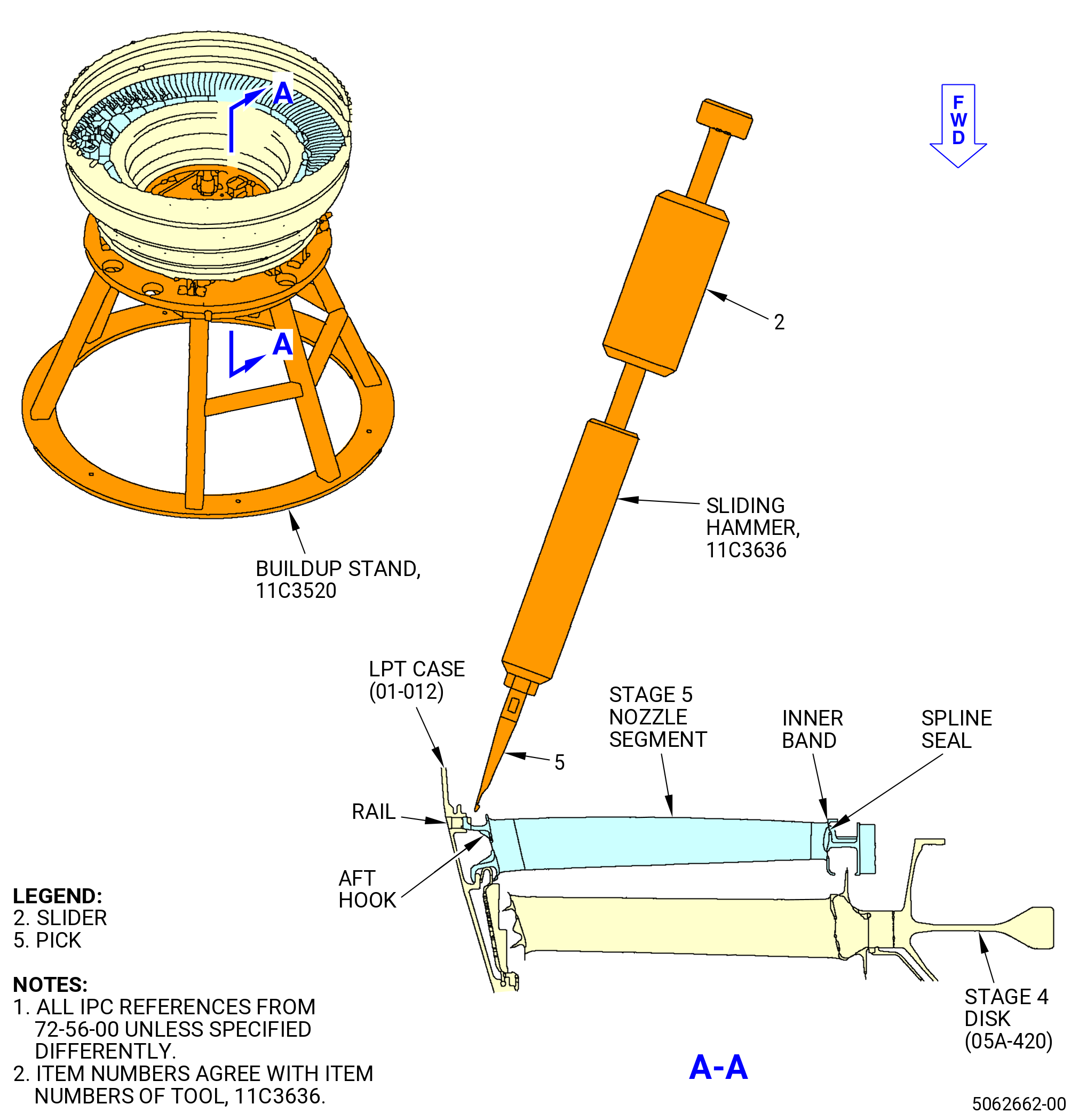
| J. | Remove the stage 5 nozzle segments from the LPT case 01-012) as follows. Refer to Figure 516. |
| (1) | Disengage the stage 5 nozzle segments from the rail of the LPT case (01-012). |
| (a) | Move the inboard end of the stage 5 nozzle segments forward on the 11C3520 buildup stand. Refer to Figure 502. |
| (b) | If necessary, lightly tap the inner band aft lips of the stage 5 segments with a mallet. This will disengage the aft hook of the outer band from the rail of the LPT case (01-012). |
| (c) | Engage the pick (item 5) of the 11C3636 sliding hammer with the anti-rotation slot of the stage 5 nozzle segments. |
| (d) | Quickly move the slider (item 2) to disengage the stage 5 nozzle segments from the LPT case (01-012). |
| (2) | Remove the stage 5 nozzle segments. |
| Subtask 72-56-00-040-145 |
| * * * PRE SB 72-0459( Old Design of Stage 5 Nozzle Segments ) |
| (3) | Remove and discard the spline seals (10A-090) (SIN 935YD) from the grooves of the stage 5 nozzle segments. |
| NOTE: |
|
| * * * END PRE SB 72-0459 |
| Subtask 72-56-00-040-146 |
| (4) | Adjust the LPT rotors aft to the NOMINAL position on the 11C3520 buildup stand. Refer to Figure 502. |
|
|
| Subtask 72-56-00-040-125 |
| K. | Remove the stage 4 disk (05A-420) and blade assembly, and the stage 4 rotating air seal from the LPT case (01-012) as follows: |
| CAUTION: |
|
| (1) | Remove the nuts and bolts from the stage 3 disk (05A-290), stage 4 rotating air seal, and stage 4 disk. Refer to Figure 517. |
| (2) | Prepare the 11C3541 LPT disk lift/turn fixture to lift the stage 4 disk and blade assembly. Refer to Figure 504 and do as follows: |
| (a) | Install the set of feet marked for stage 4 (item 133) into the lift bars (item 129) and insert the ball lock pins (item 93). |
| NOTE: |
|
| (b) | Install the bar/foot assemblies into the legs of the spider (item 128). |
| 1 | Adjust the positions of two of the lift bars (item 129) so the scribed lines for stage 4 align with the edges of the spider legs. |
| 2 | Insert the ball lock pins (item 92) to lock the two lift bars (item 129) to the spider. |
| 3 | Fully insert a third lift bar (item 129) into the third spider leg. |
| (3) | Install the 11C3541 LPT disk lift/turn fixture on the stage 4 disk as follows: |
| (a) | Install the lift arm (item 45) into the clevis (item 102) and insert the ball lock pin (item 25). |
| (b) | Attach an overhead hoist to the lift arm (item 45). |
| WARNING: |
|
| CAUTION: |
|
| (c) | Carefully lift the 11C3541 LPT disk lift/turn fixture and lower it in the bore of the stage 4 disk. |
| (d) | Extend the third lift bar (item 129) that you inserted in the third spider leg. |
| 1 | Adjust the position of the lift bar (item 129) so the scribed line for stage 4 aligns with the edge of the spider leg. |
| 2 | Lock the lift bar (item 129) in the spider (item 128) with the ball lock pins (item 92). |
| WARNING: |
|
| (4) | Lift the stage 4 disk and blade assembly from the LPT case (01-012) and put the assembly in a safe location. Refer to Figure 517. |
| (5) | Remove the 11C3541 LPT disk lift/turn fixture from the stage 4 disk and blade assembly. Refer to Figure 504 and do as follows: |
| (a) | Remove the ball lock pins (item 92) from the one of the three legs of the spider (item 128). |
| (b) | Retract the lift bar (item 129). |
| WARNING: |
|
| (c) | Lift the 11C3541 LPT disk lift/turn fixture from the stage 4 disk. |
| (6) | Remove the stage 4 rotating air seal from the stage 3 disk. Refer to Figure 517. |
| Subtask 72-56-00-040-126 |
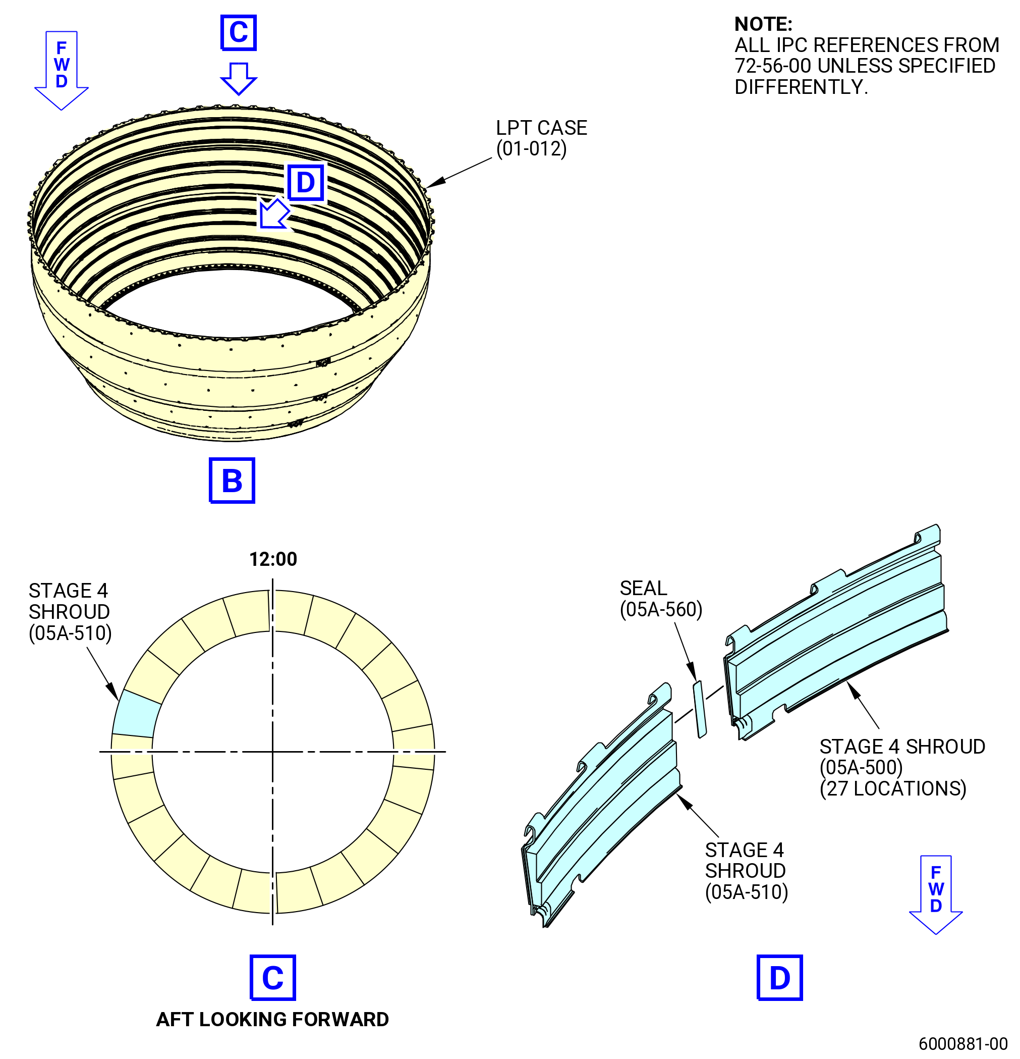
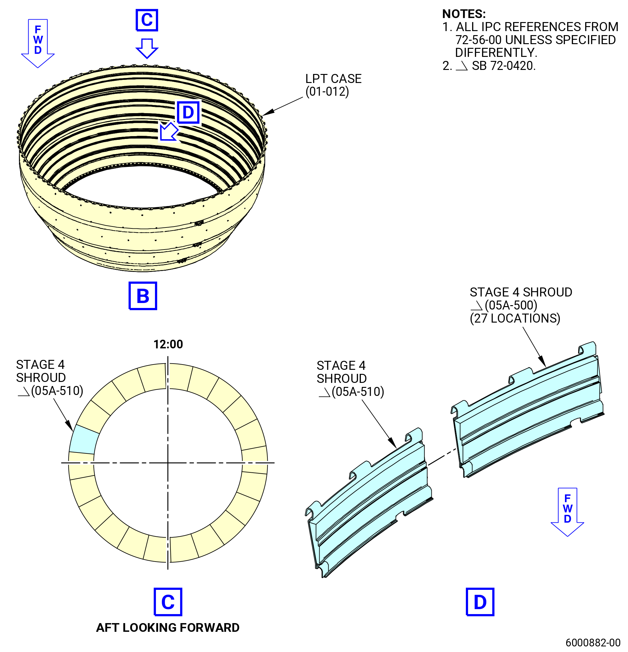
| L. | Remove the stage 4 shrouds (05A-500) (SIN 935B4) and (05A-510) (SIN 935BF) from the LPT case (01-012) (SIN 935C1). Refer to Figure 518 and as follows: |
| (1) | Move the aft ends of the stage 4 shrouds radially in to disengage the rail of the LPT case (01-012). |
| (2) | Remove the stage 4 shrouds. |
| Subtask 72-56-00-040-144 |
| * * * PRE SB 72-0420( Old Design of Stage 4 Shrouds ) |
| (3) | Remove and discard the stage 4 shroud seals (seals) (05A-560) (SIN 935YC). |
| NOTE: |
|
| * * * END PRE SB 72-0420 |
| Subtask 72-56-00-040-127 |
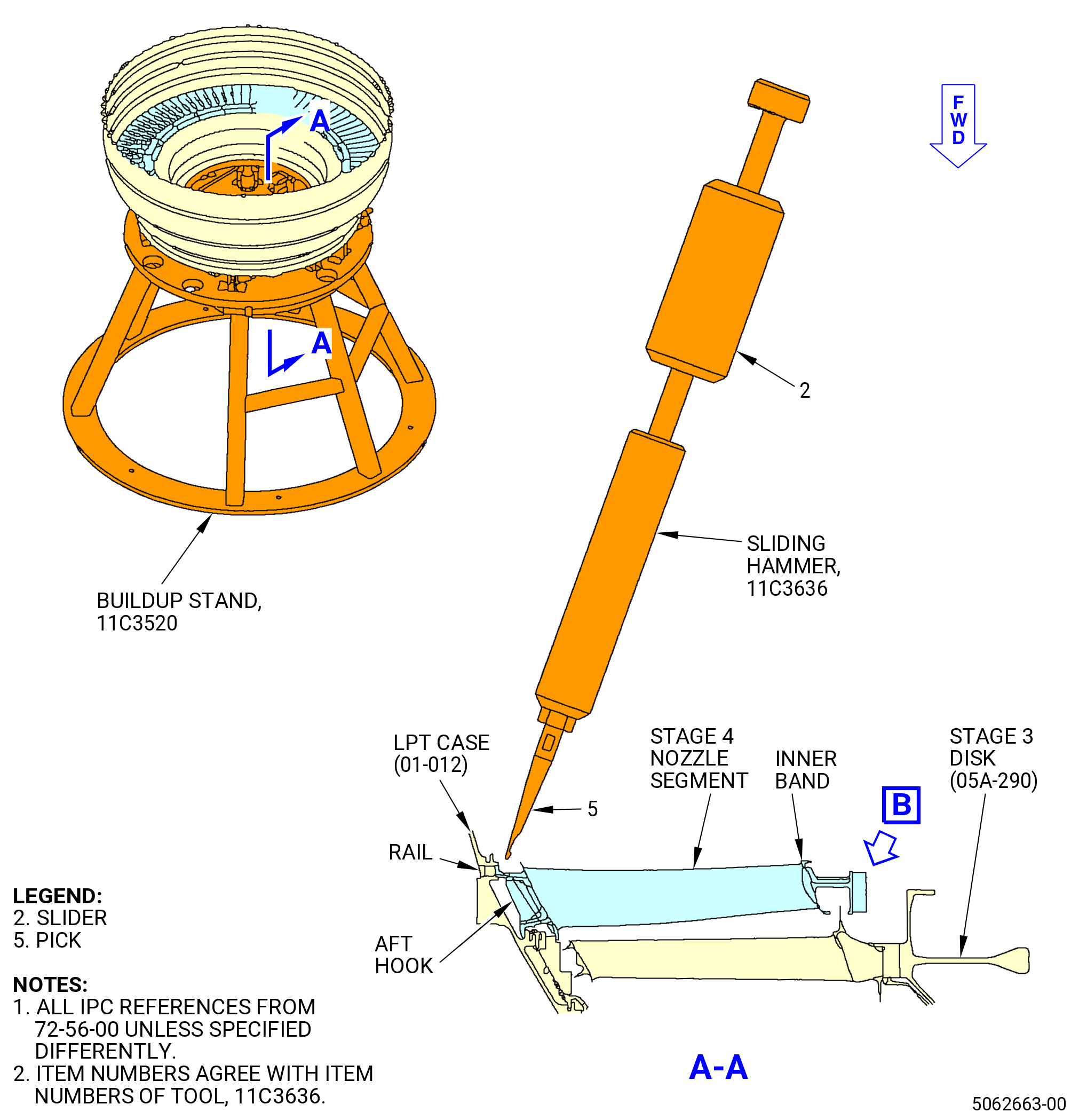
| M. | Remove the stage 4 nozzle segments from the LPT case (01-012). |
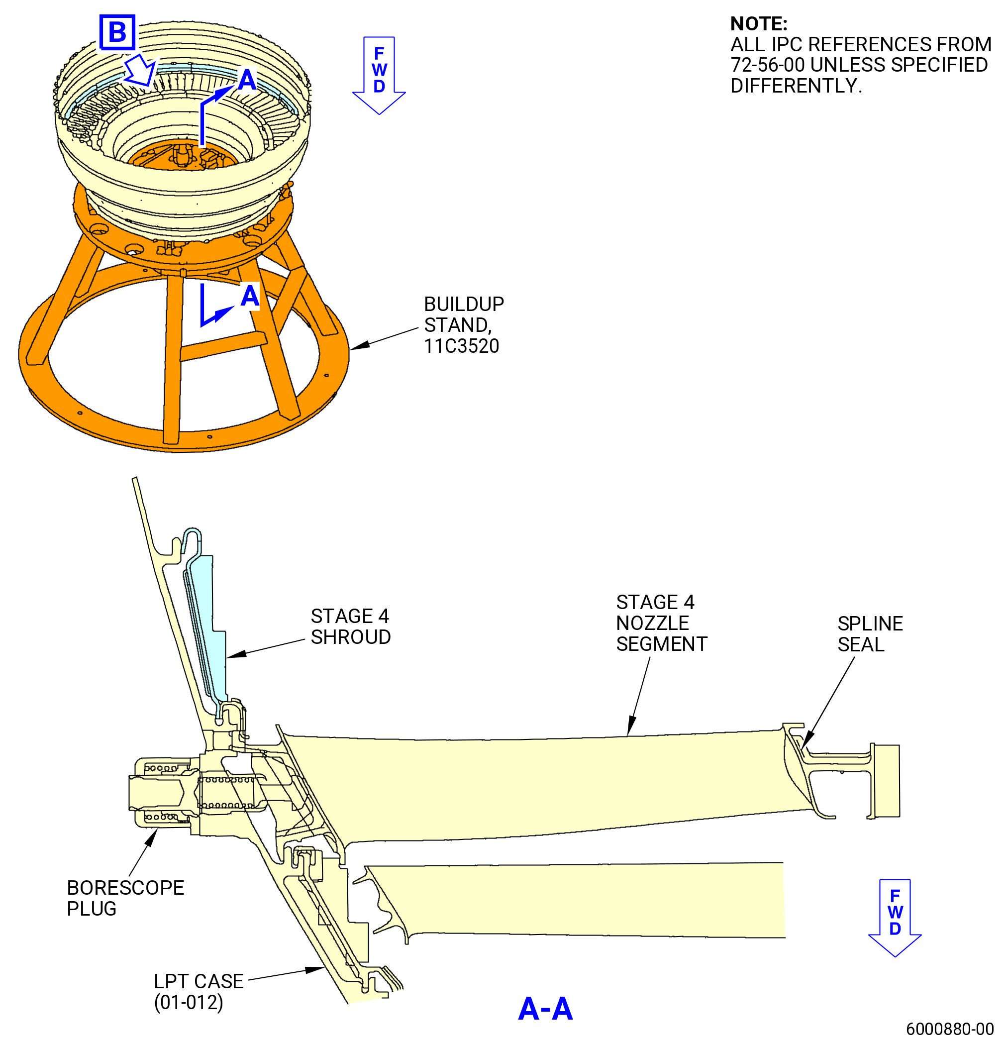
| (1) | Remove the borescope plug from the LPT case (01-012) and the stage 4 nozzle segment at the 9:30 o'clock position. Refer to Figure 518. |
| (2) | Disengage the stage 4 nozzle segments from the rail of the LPT case (01-012) as follows. Refer to Figure 519. |
| (a) | Move the inboard end of the stage 4 nozzle segments forward on the 11C3520 buildup stand. Refer to Figure 502. |
| (b) | If necessary, lightly tap the inner band aft lips of the stage 4 segments with a mallet. This will disengage the aft hook of the outer band from the rail of the LPT case (01-012). |
| (c) | Engage the pick (item 5) of the 11C3636 sliding hammer with the anti-rotation slot of the stage 4 nozzle segments. |
| (d) | Quickly move the slider (item 2) to disengage the stage 4 nozzle segments from the LPT case (01-012). |
| (3) | Remove the stage 4 nozzle segments. |
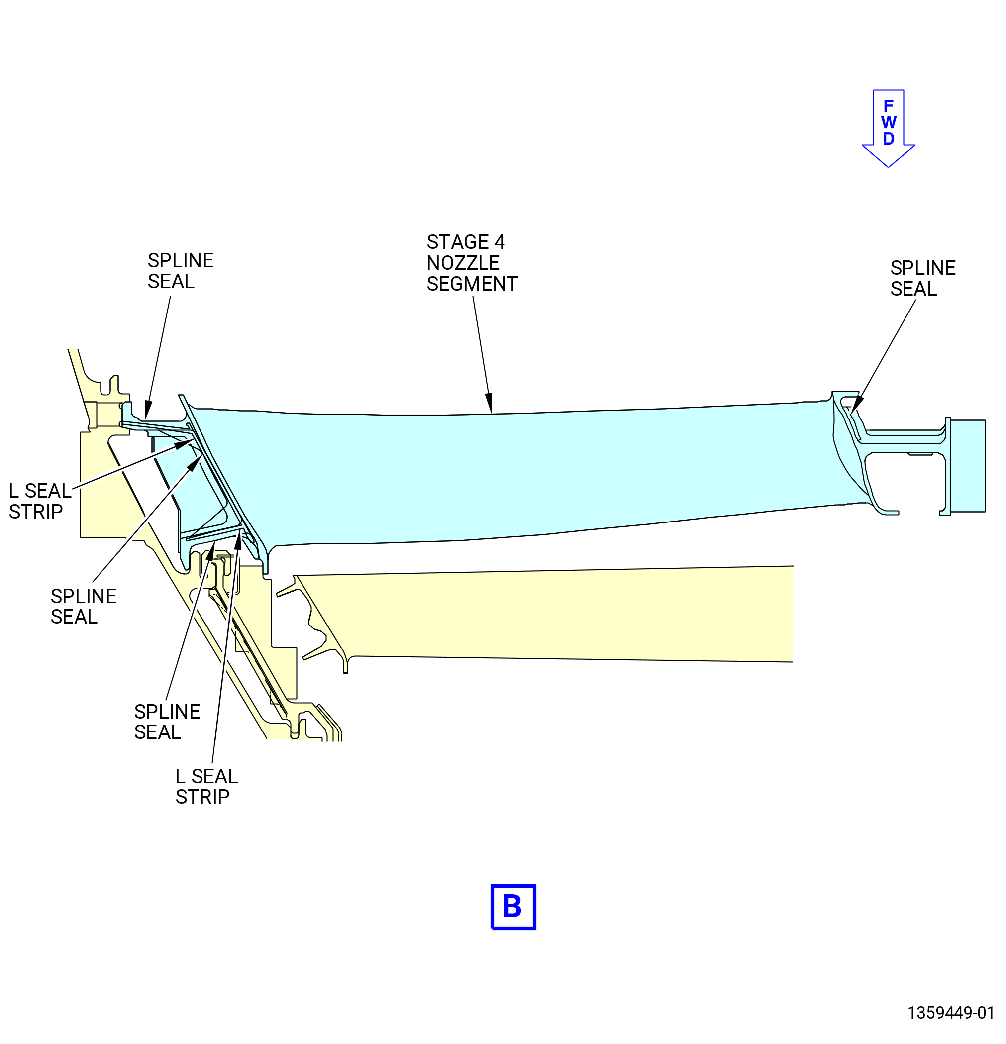
| (4) | Remove the LPT stage 4 spline seals (spline seal) (05A-520) (SIN 935Y7), (05A-530) (SIN 935Y8), (05A-540) (SIN 935Y9), and (05A-550) (SIN 935YA) and the L seal strips (05A-650) (SIN 935YF) and (05A-660) (SIN 935YG) from the grooves of the stage 4 nozzle segments and discard them. |
| (5) | Move the LPT rotors aft to the NOMINAL position on the 11C3520 buildup stand. Refer to Figure 502. |
|
|
| Subtask 72-56-00-040-128 |
| N. | Remove the stage 3 disk (05A-290) and blade assembly, and the stage 3 rotating air seal as follows: |
| CAUTION: |
|
| (1) | Remove the nuts and bolts from the stage 2 disk (05A-120), stage 3 rotating air seal, and stage 3 disk. Refer to Figure 520. |
| (2) | Prepare the 11C3541 LPT disk lift/turn fixture to lift the stage 3 disk and blade assembly. Refer to Figure 504 and do as follows: |
| (a) | Install the set of feet marked for stage 3 (item 132) into the lift bars (item 129) and insert the ball lock pins (item 93). |
| NOTE: |
|
| (b) | Install the bar/foot assemblies into the legs of the spider (item 128). |
| 1 | Adjust the positions of two of the lift bars (item 129) so the scribed lines for stage 3 align with the edges of the spider legs. |
| 2 | Insert two of the ball lock pins (item 92) to lock the two lift bars (item 129) to the spider. |
| 3 | Fully insert a third lift bar (item 129) into the third spider leg. |
| (3) | Install the 11C3541 LPT disk lift/turn fixture to the stage 3 disk as follows: |
| (a) | Install the lift arm (item 45) into the clevis (item 102) and insert the ball lock pin (item 25). |
| (b) | Attach an overhead hoist to the lift arm (item 45). |
| WARNING: |
|
| CAUTION: |
|
| (c) | Carefully lift the 11C3541 LPT disk lift/turn fixture and lower it in the bore of the stage 3 disk. |
| (d) | Extend the third lift bar (item 129) that you inserted in the spider leg. |
| 1 | Adjust the position of the lift bar (item 129) so that the scribed line for stage 3 aligns with the edge of the spider leg. |
| 2 | Lock the lift bar (item 129) in the spider (item 128) with the ball lock pins (item 92). |
| WARNING: |
|
| (4) | Lift the stage 3 disk and blade assembly from the LPT case (01-012) and put the assembly in a safe location. Refer to Figure 520. |
| (5) | Remove the 11C3541 LPT disk lift/turn fixture from the stage 3 disk and blade assembly. Refer to Figure 504 and do as follows: |
| (a) | Remove the ball lock pins (item 92) from one of the three legs of the spider (item 128). |
| (b) | Retract the lift bar (item 129). |
| WARNING: |
|
| (c) | Lift the 11C3541 LPT disk lift/turn fixture from the stage 3 disk. |
| (6) | Remove the stage 3 rotating air seal from the stage 2 disk (05A-120). |
| Subtask 72-56-00-040-129 |
| O. | Remove the stage 3 shrouds from the LPT case (01-012) as follows. Refer to Figure 521 and Figure 522. |
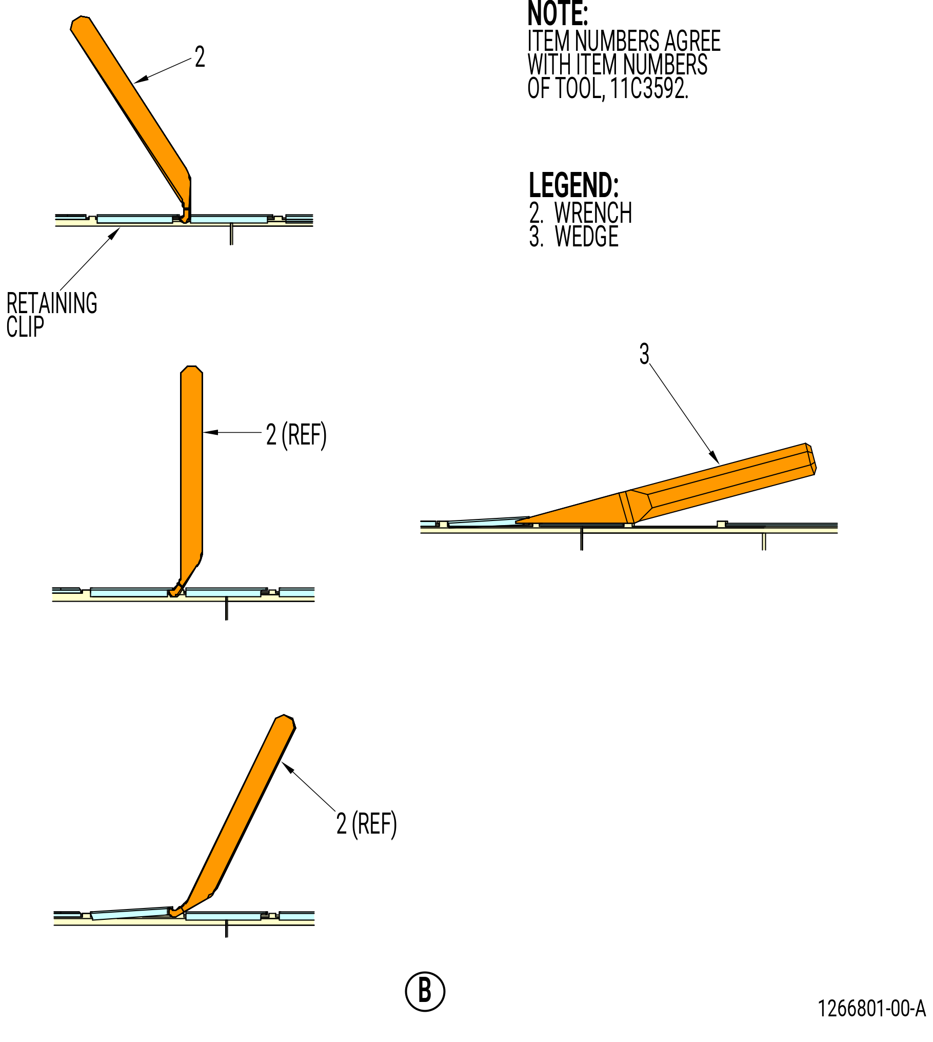
| (1) | Remove and discard the stage 3 shroud retainer clips (05A-350) (SIN 935B9) from the stage 3 shrouds with the 11C3592 shroud remove tool as follows: |
| (a) | Insert the tip of the wrench (item 2) under the outer end of the retaining clip. |
| (b) | Pull the retaining clip upward as far as possible with the wrench (item 2). |
| (c) | Insert the wedge (item 3) under the partially removed retainer clip. |
| (d) | Hit the wedge (item 3) with a nylon bar and steel hammer to push it equally under the retainer clip. |
| (e) | Hit the wedge again until the retainer clip is fully removed. |
| (f) | Do the above steps again to remove all the retainer clips. |
| CAUTION: |
|
| (2) | Move the aft ends of the stage 3 shrouds radially in and disengage the rail from the edge of the LPT case (01-012). |
| (3) | Lift the stage 3 shrouds to remove them. |
| (4) | Remove and discard the shroud stage 3 seal (seal) (05A-360) (SIN 935W3). |
| Subtask 72-56-00-040-130 |
| P. | Remove the stage 3 nozzle segments from the LPT case (01-012) as follows. Refer to Figure 523. |
| (1) | Disengage the stage 3 nozzle segments from the rail of the LPT case (01-012). |
| (a) | Move the inboard end of the stage 3 nozzle segments forward on the 11C3520 buildup stand. Refer to Figure 502. |
| (b) | If necessary, lightly tap the inner band aft lips of the stage 3 segments with a mallet. This will disengage the aft hook of the outer band from the rail of the LPT case (01-012). |
| (c) | Engage the pick (item 5) of the 11C3636 sliding hammer with the anti-rotation slot of the stage 3 nozzle segments. |
| (d) | Quickly move the slider (item 2) to disengage the stage 3 nozzle segments from the LPT case (01-012). |
| (2) | Remove the stage 3 nozzle segments. |
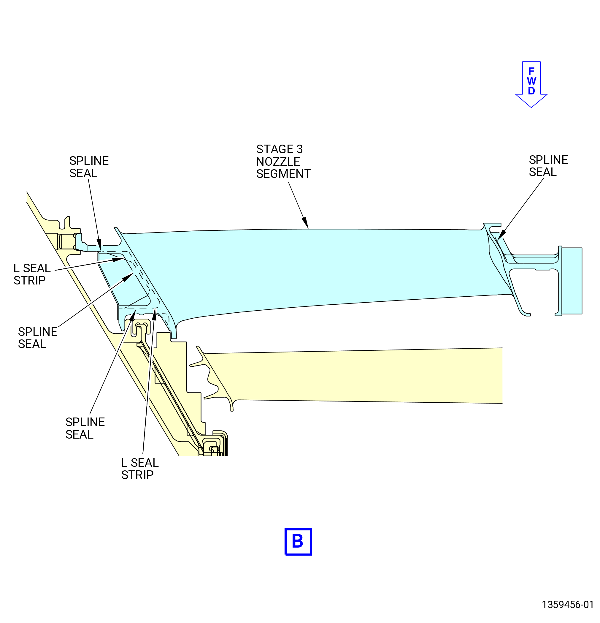
| (3) | Remove the LPT stage 3 spline seals (spline seal) (05A-370) (SIN 935W7), (05A-380) (SIN 935Y4), (05A-390) (SIN 935Y5), and (05A-400) (SIN 935Y6) and the L seal strips (05A-680) (SIN 935YJ) and (05A-690) (SIN 935YK) from the grooves of the stage 3 nozzle segments and discard them. |
| (4) | Move the LPT rotors aft to the NOMINAL position on the 11C3520 buildup stand. Refer to Figure 502. |
| Subtask 72-56-00-040-131 |
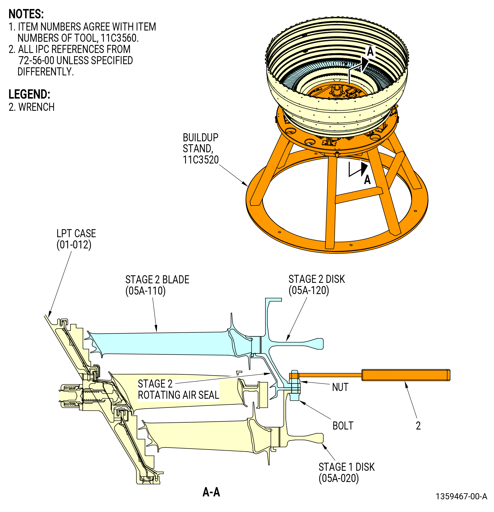
| Q. | Remove the stage 2 disk (05A-120) and blade assembly and the stage 2 rotating air seal from the LPT case (01-012) as follows: |
| CAUTION: |
|
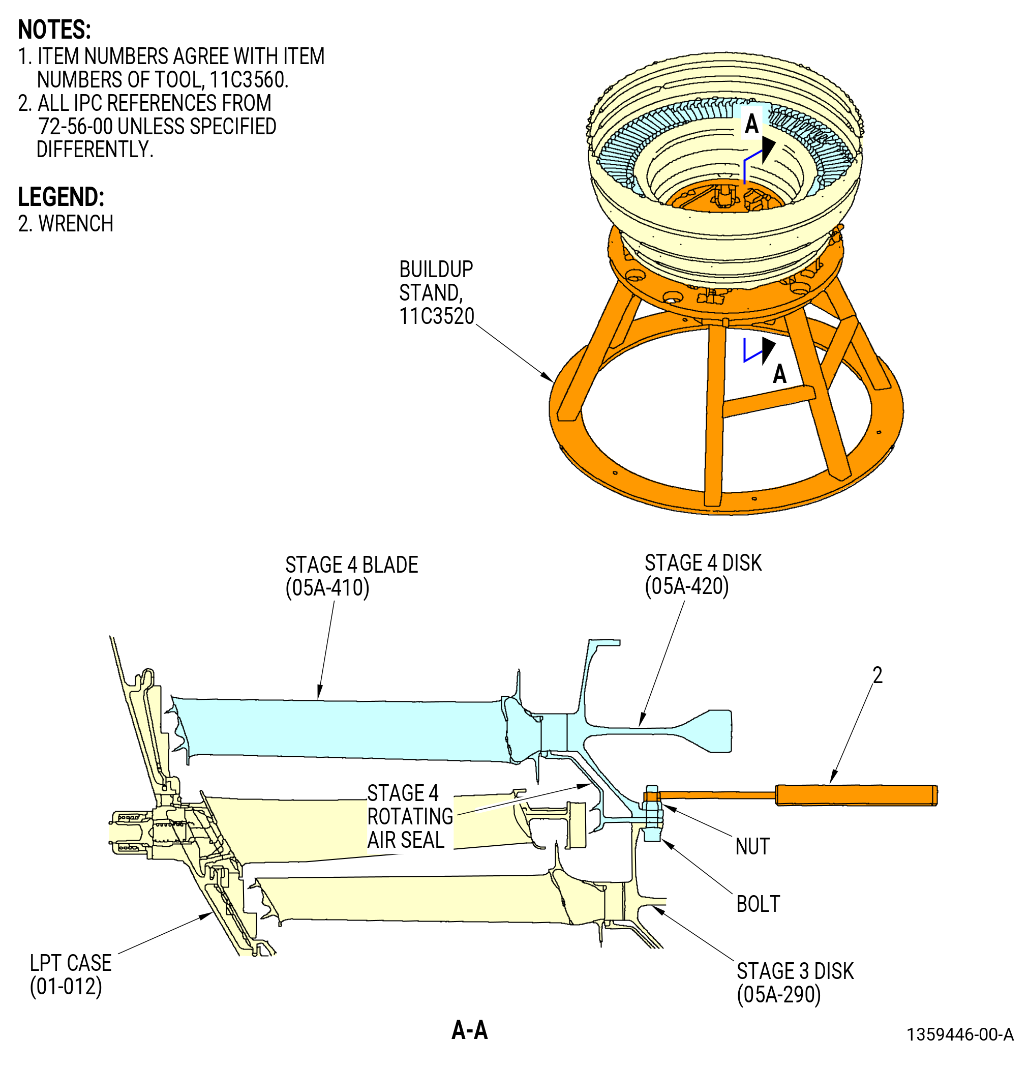
| (1) | Remove the nuts and bolts from the stage 1 disk (05A-020), stage 2 rotating air seal, and stage 2 disk (05A-120). Use the wrench (item 2) of the 11C3560 nut tighten wrench. Refer to Figure 524. |
| (2) | Prepare the 11C3541 LPT disk lift/turn fixture to lift the stage 2 disk (05A-120) and blade assembly. Refer to Figure 504 and do as follows: |
| (a) | Install the set of feet marked for stage 2 (item 131) into the lift bars (item 129) and insert the ball lock pins (item 93). |
| NOTE: |
|
| (b) | Install the bar/foot assemblies into the legs of the spider (item 128). |
| 1 | Adjust the positions of two of the lift bars (item 129) so the scribed lines for stage 2 align with the edges of the spider legs. |
| 2 | Insert the ball lock pins (item 92) to lock the two lift bars (item 129) to the spider (item 128). |
| 3 | Fully insert a third lift bar (item 129) into the third spider leg. |
| (3) | Install the 11C3541 LPT disk lift/turn fixture on the stage 2 disk (05A-120) as follows: |
| (a) | Install the lift arm (item 45) in the clevis (item 102) and insert the ball lock pin (item 25). |
| (b) | Attach an overhead hoist to the lift arm (item 45). |
| WARNING: |
|
| CAUTION: |
|
| (c) | Carefully lift the 11C3541 LPT disk lift/turn fixture and lower it in the bore of the stage 2 disk (05A-120) (SIN 930B2). |
| (d) | Extend the third lift bar (item 129) that you inserted in the third spider leg. |
| 1 | Adjust the position of the lift bar so the scribed line for stage 2 aligns with the edge of the spider leg. |
| 2 | Lock the lift bar in the spider (item 128) with the ball lock pins (item 92). |
| WARNING: |
|
| (4) | Lift the stage 2 disk (05A-120) and blade assembly from the LPT case (01-012) and put the assembly in a safe location. Refer to Figure 524. |
| (5) | Remove the 11C3541 LPT disk lift/turn fixture from the stage 2 disk (05A-120) (SIN 930B2) and blade assembly. Refer to Figure 504 and do as follows: |
| (a) | Remove the ball lock pins (item 92) from one of the three legs of the spider (item 128). |
| (b) | Retract the lift bar (item 129). |
| WARNING: |
|
| (c) | Lift the 11C3541 LPT disk lift/turn fixture from the stage 2 disk (05A-120). |
| (6) | Remove the stage 2 rotating air seal from the stage 1 disk (05A-020). Refer to Figure 524. |
| Subtask 72-56-00-040-132 |
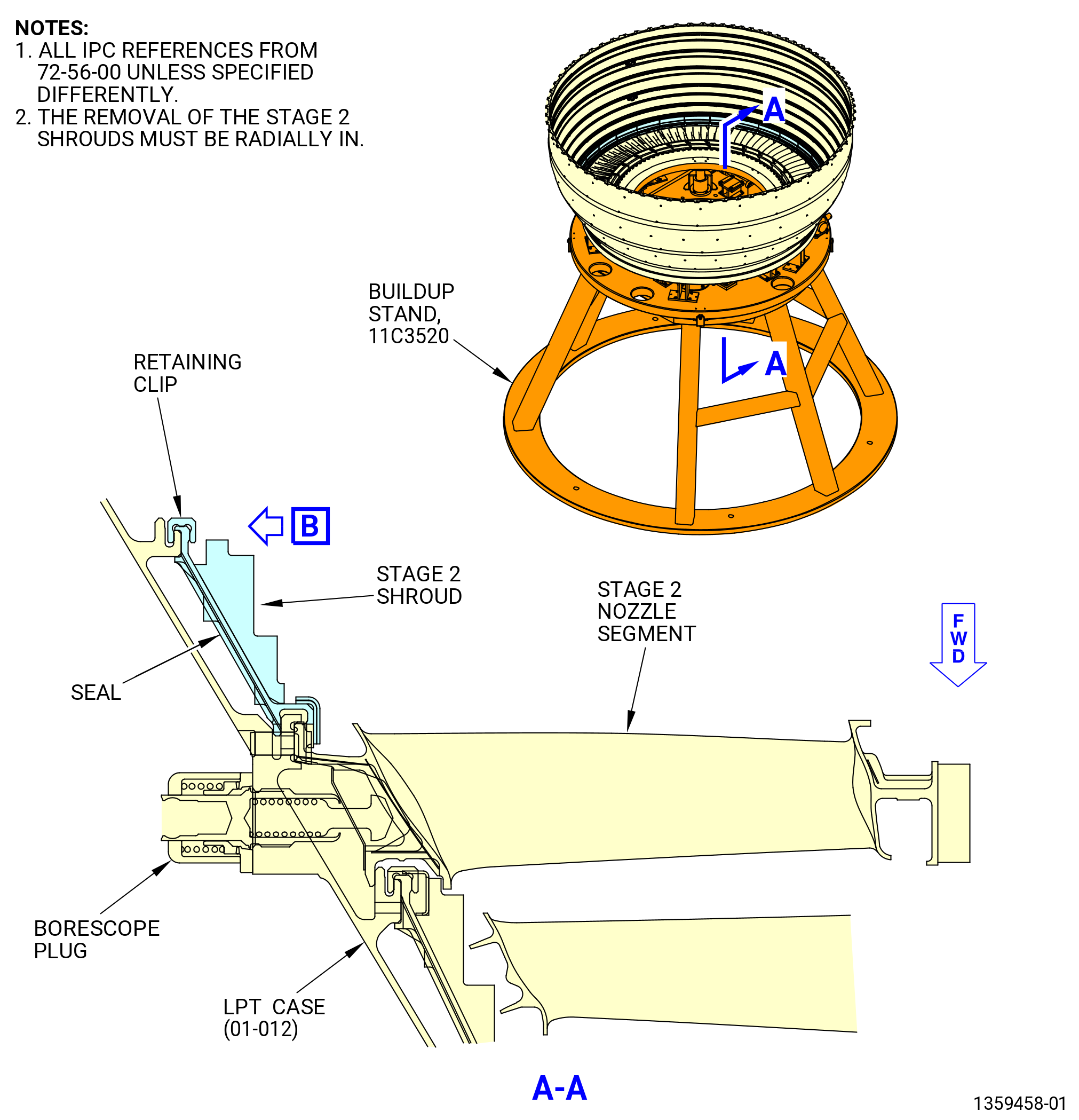
| R. | Remove the stage 2 shrouds from the LPT case (01-012) as follows. Refer to Figure 525 and Figure 522. |
| (1) | Remove and discard the stage 2 shroud retainer clips (05A-180) (SIN 935B8) from the stage 2 shrouds with the 11C3592 shroud remove tool. |
| (a) | Insert the tip of the wrench (item 2) under the outer end of the retaining clip. |
| (b) | Pull the retaining clip up as far as possible with the wrench (item 2). |
| (c) | Insert the wedge (item 3) under the partially removed retainer clip. |
| (d) | Hit the wedge (item 3) with a nylon bar and steel hammer to push it equally under the retainer clip. |
| (e) | Hit the wedge again until the retainer clip is fully removed. |
| (f) | Do the above steps again to removed all the retainer clips. |
| CAUTION: |
|
| (2) | Move the aft ends of the stage 2 shrouds radially in to disengage the rail from the edge of the LPT case (01-012). |
| (3) | Lift the stage 2 shrouds to remove them. |
| (4) | Remove and discard the shroud stage 2 seal (seal) (05A-190) (SIN 935W2). |
| Subtask 72-56-00-040-133 |
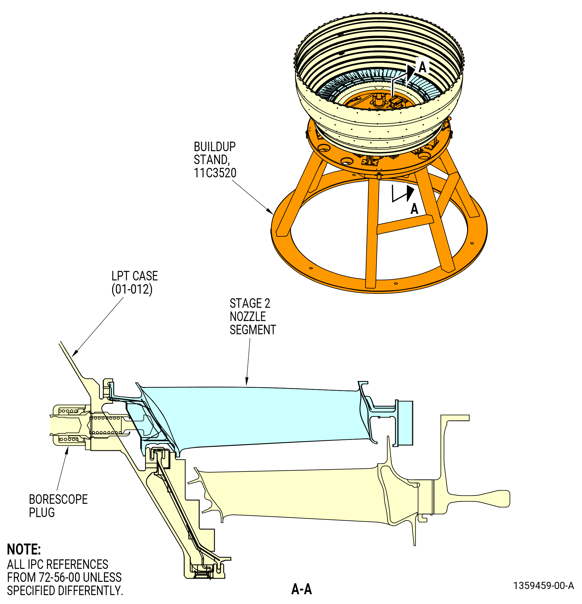
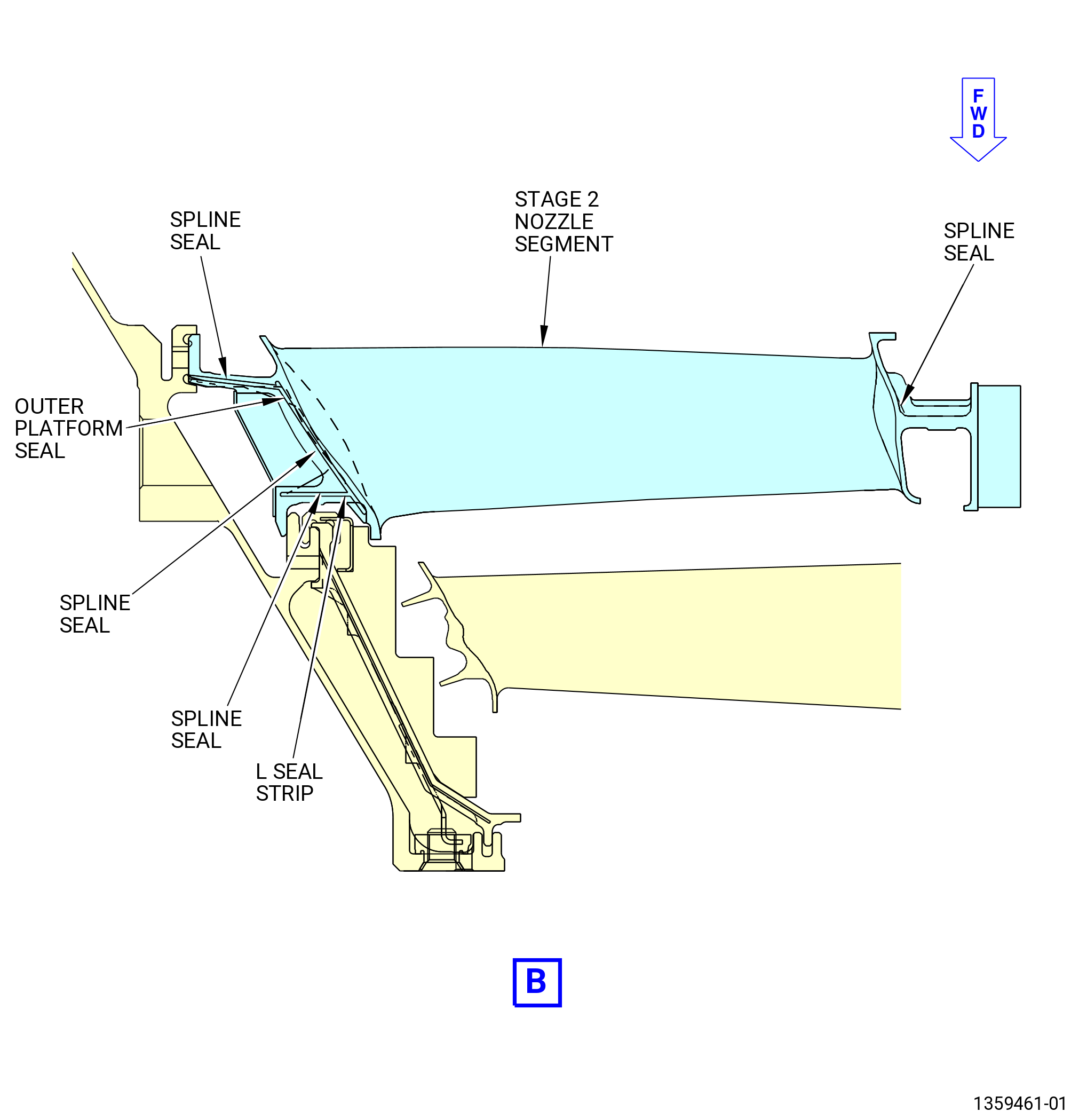
| S. | Remove the stage 2 nozzle segments from the LPT case (01-012) as follows: |
| (1) | Remove the borescope plug from the LPT case (01-012) and the stage 2 nozzle segment at the 9:30 o'clock position. Refer to Figure 526. |
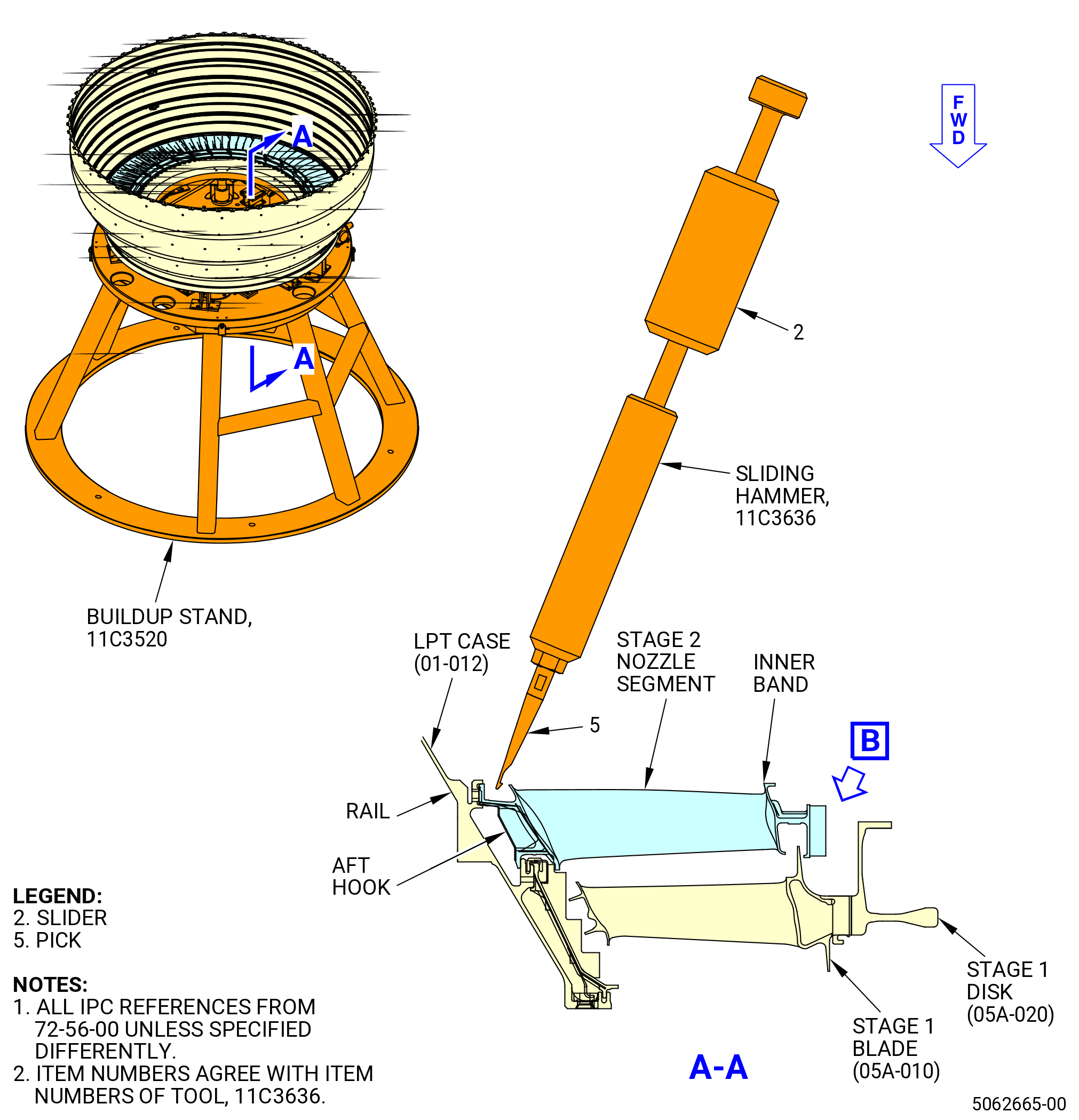
| (2) | Disengage the stage 2 nozzle segments from the rail of the LPT case (01-012). Refer to Figure 527. |
| (a) | Move the inboard end of the stage 2 nozzle segments forward on the 11C3520 buildup stand. Refer to Figure 502. |
| (b) | If necessary, lightly tap the inner band aft lips of the stage 2 segments with a mallet. This will disengage the aft hook of the outer band from the rail of the LPT case (01-012). |
| (c) | Engage the pick (item 5) of the 11C3636 sliding hammer with the anti-rotation slot of the stage 2 nozzle segments. |
| (d) | Quickly move the slider (item 2) to disengage the stage 2 nozzle segments from the LPT case (01-012). |
| (3) | Remove the stage 2 nozzle segments. |
| (4) | Remove the LPT stage 2 spline seals (spline seal) (05A-200) (SIN 935Y0), (05A-210) (SIN 935Y1), (05A-220) (SIN 935Y2), and (05A-230) (SIN 935Y3), outer platform seal (05A-570) (SIN 935YE), and the L seal strips (05A-630) (SIN 935T6), (05A-640) (SIN 935T7), and (05A-670) (SIN 935YH) from the grooves of the stage 2 nozzle segments and discard them. |
| (5) | Move the LPT rotors aft to the NOMINAL position on the 11C3520 buildup stand. Refer to Figure 502. |
| Subtask 72-56-00-040-134 |
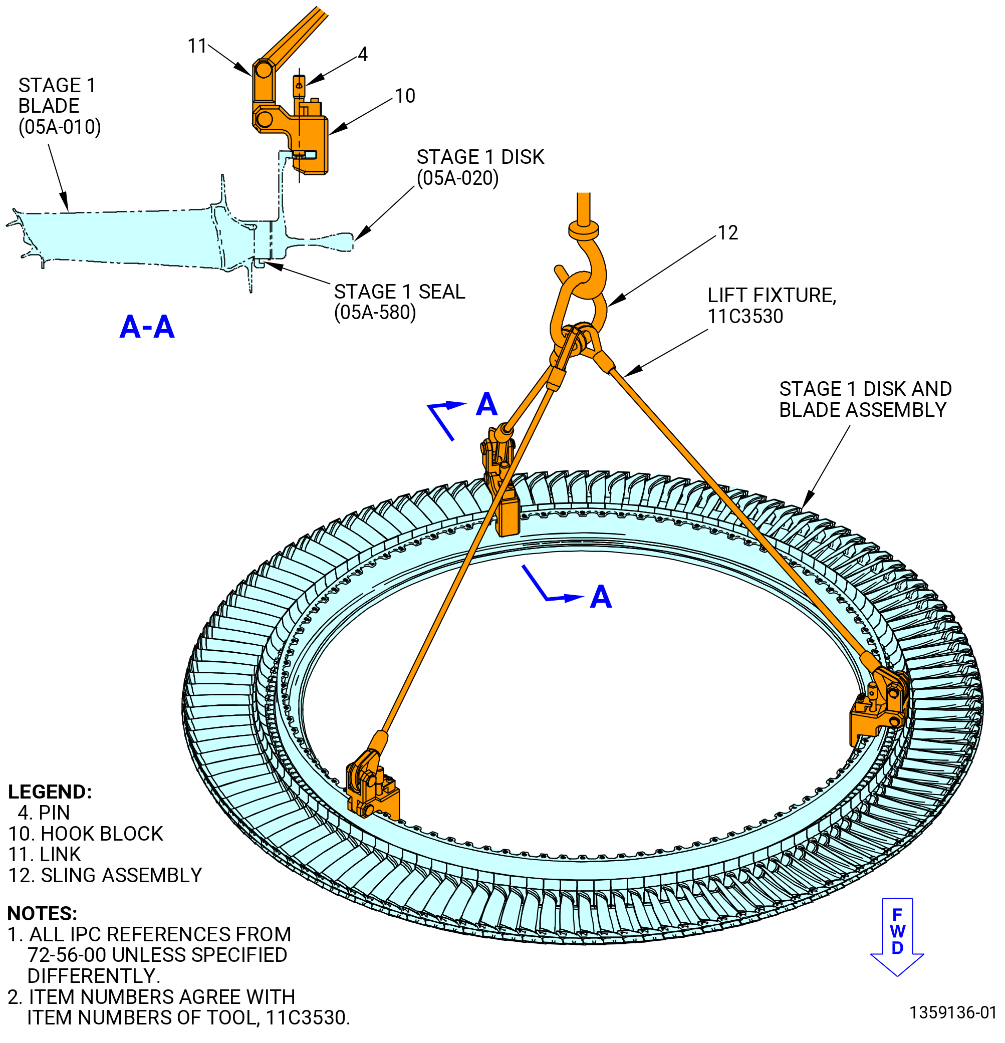
| T. | Remove the stage 1 disk (05A-020) and blade assembly from the LPT case (01-012) as follows: |
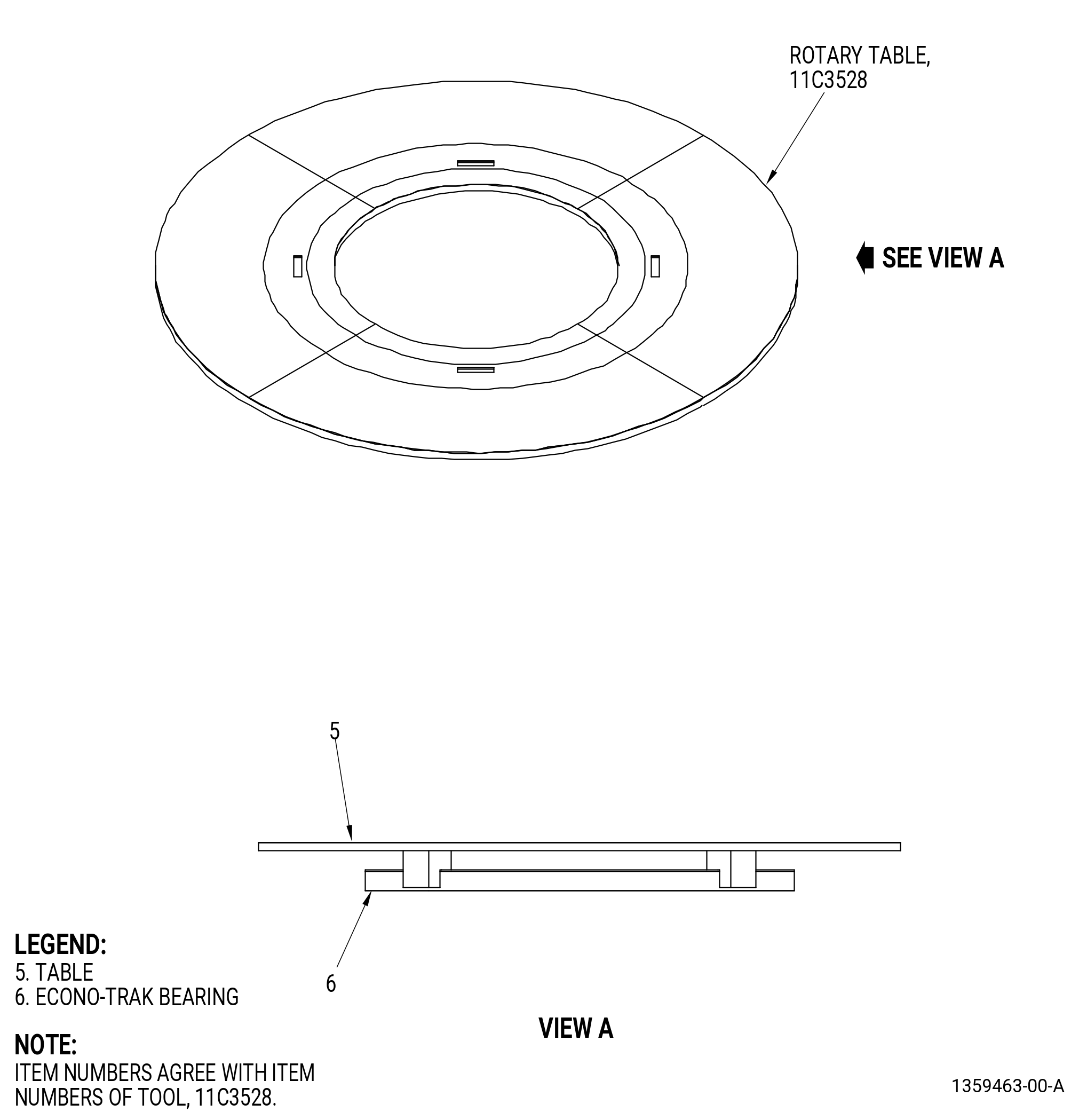
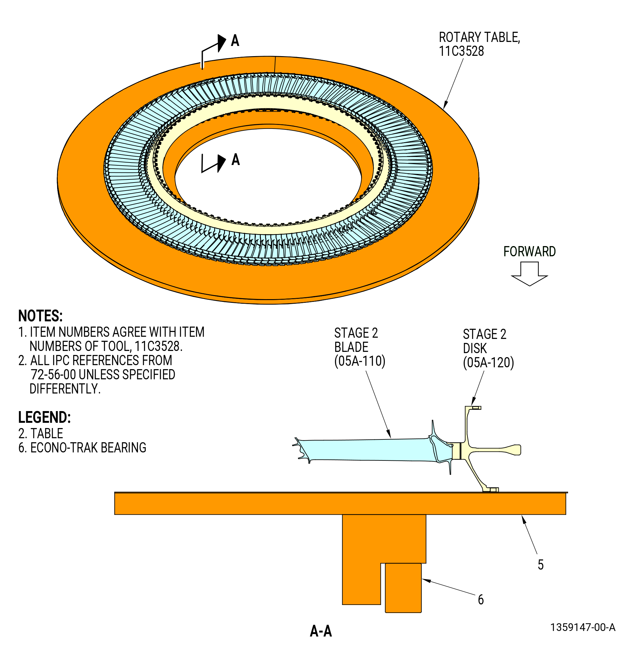
| (1) | Prepare the 11C3528 rotary table for the stage 1 disk and blade assembly. Refer to Figure 528. |
| (a) | Put the table (item 5) on the econo-trak bearing (item 6) so it is level. |
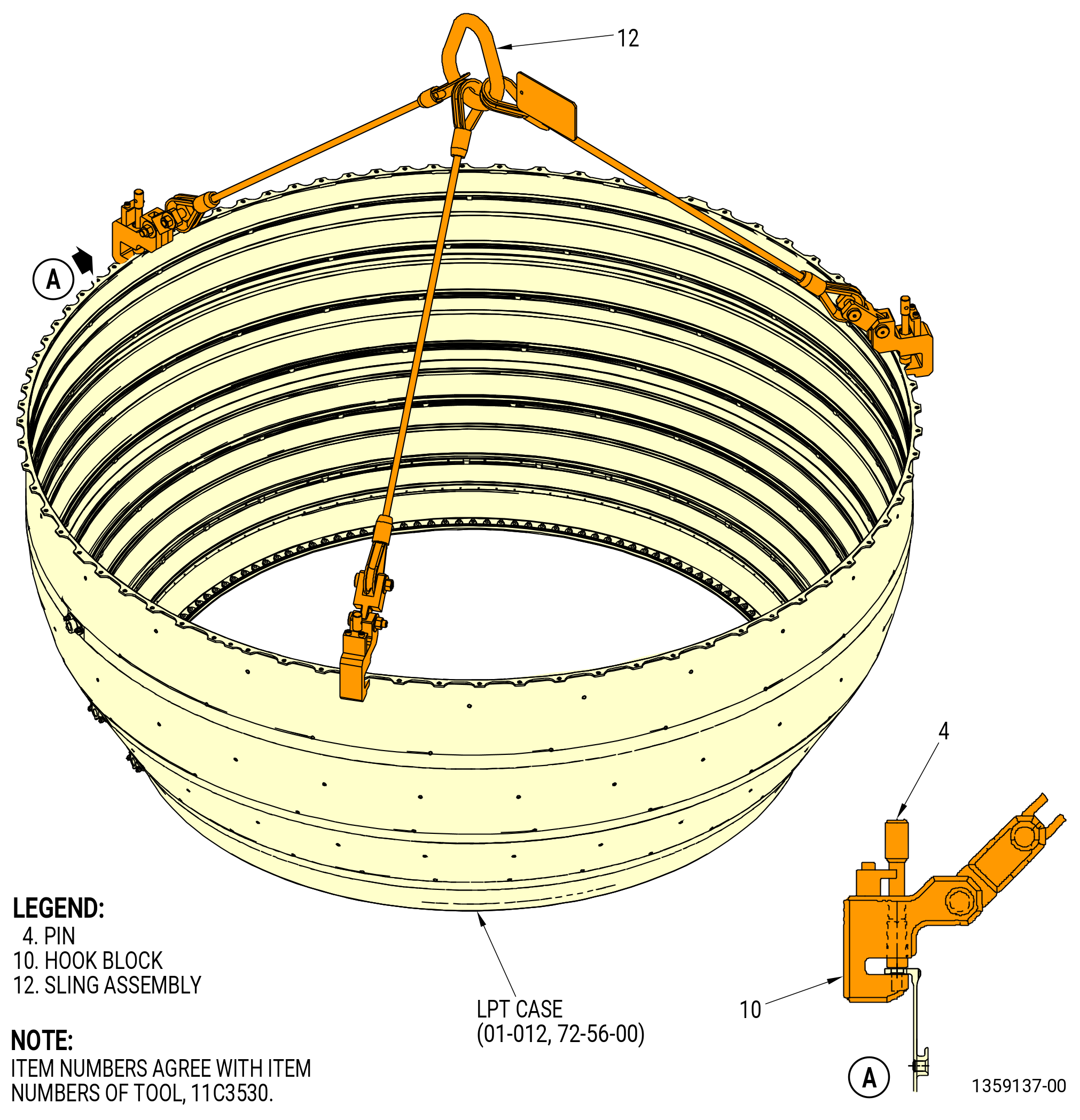
| (2) | Install the 11C3530 lift fixture on the stage 1 disk as follows. Refer to Figure 529. |
| (a) | Pull the pins (item 4) out from the hook blocks (item 10). |
| (b) | Attach the hook blocks (item 10) to the flange of the stage 1 disk at three equally spaced bolthole locations. |
| (c) | Install the pins (item 4) in the hook blocks (item 10). |
| (3) | Attach an overhead hoist to the sling assembly (item 12). |
| WARNING: |
|
| (4) | Lift the stage 1 disk and blade assembly from the LPT case (01-012). |
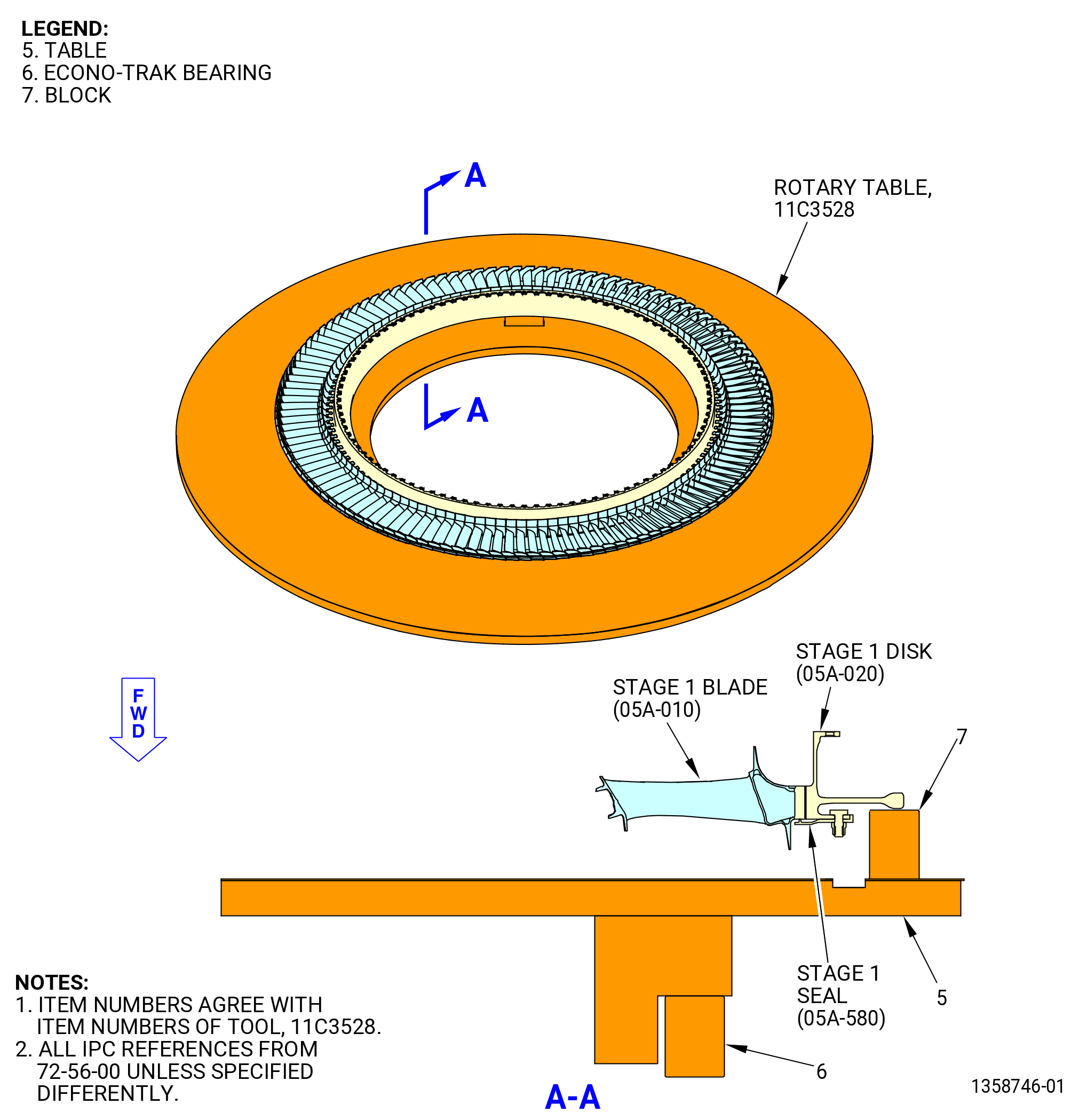
| (5) | Install the stage 1 disk and blade assembly on the 11C3528 rotary table as follows. Refer to Figure 530. |
| (a) | Lower the stage 1 disk and blade assembly on the 11C3528 rotary table. |
| (b) | Put the blocks (item 7) on the table (item 5) so the blocks give support to the hub of the stage 1 disk. |
| (c) | Continue to lower the stage 1 disk and blade assembly on the blocks (item 7). |
| (6) | Remove the overhead hoist and the 11C3530 lift fixture from the stage 1 disk and blade assembly. |
| Subtask 72-56-00-040-135 |
| U. | Remove the stage 1 shrouds from the LPT case (01-012) as follows. Refer to Figure 531 and Figure 522. |
| (1) | Remove and discard the stage 1 shroud retainer clips (05A-080) (SIN 935B7) from the stage 1 shrouds with the 11C3592 shroud remove tool. |
| (a) | Insert the tip of the wrench (item 2) under one end of a retaining clip. |
| (b) | Pull the retaining clip up as far as possible with the wrench (item 2). |
| (c) | Insert the wedge (item 3) under the partially removed retainer clip. |
| (d) | Hit the wedge (item 3) with a nylon bar and steel hammer and push it equally under the retainer clip. |
| (e) | Hit the wedge again until the retainer clip is fully removed. |
| (f) | Do the above steps again to remove all the retainer clips. |
| CAUTION: |
|
| (2) | Move the aft ends of the stage 1 shrouds radially in to disengage the rail from the edge of the LPT case (01-012). |
| (3) | Lift the stage 1 shrouds to remove them. |
| (4) | Remove the stage 1 shroud seals (seal) (05A-090) (SIN 935W1) and (05A-100) (SIN 935W8) and the L seal strips (05A-700) (SIN 935YL) and discard them. |
| Subtask 72-56-00-040-136 |
| V. | Remove the LPTR stage 1 seal (stage 1 seal) (05A-580) (SIN 930C1) from the stage 1 disk (05A-020) (SIN 930B1) as follows: |
| (1) | Prepare the 11C3541 LPT disk lift/turn fixture to lift the stage 1 disk and blade assembly. Refer to Figure 504 and do as follows: |
| (a) | Install the set of feet (item 130) marked for stage 1 into the lift bars (item 129) and insert the ball lock pins (item 93). |
| NOTE: |
|
| (b) | Install the lift bar/foot assemblies into the legs of the spider (item 128). |
| 1 | Adjust the positions of two of the lift bars (item 129) so the scribed lines for stage 1 align with the edges of the spider legs. |
| 2 | Insert the ball lock pins (item 92) to lock the two lift bars (item 129) to the spider (item 128). |
| 3 | Fully insert the third lift bar (item 129) into the third spider leg. |
| (2) | Install the 11C3541 LPT disk lift/turn fixture on the stage 1 disk as follows: |
| (a) | Install the lift arm (item 45) into the clevis (item 102) and insert the ball lock pin (item 25). |
| (b) | Attach an overhead hoist to the lift arm (item 45). |
| WARNING: |
|
| CAUTION: |
|
| (c) | Carefully lift the 11C3541 LPT disk lift/turn fixture and lower it in the bore of the stage 1 disk. |
| (d) | Extend the third lift bar (item 129) that you inserted into the third spider leg. |
| 1 | Adjust the position of the lift bar (item 129) so the scribed line for stage 1 comes to the edge of the spider leg. |
| 2 | Lock the lift bar (item 129) in the spider (item 128) with the ball lock pins (item 92). |
| Subtask 72-56-00-040-137 |
| (3) | Turn the stage 1 disk and blade assembly over as follows. Refer to Figure 504. |
| WARNING: |
|
| (a) | Lift the stage 1 disk and blade assembly with an overhead hoist. Lift high enough to install the second lift cap (item 89) and lift arm (item 5) on the lower side of the spider (item 2). |
| (b) | Install the second lift cap (item 89) on the spider (item 2). |
| 1 | Put the lift cap on the spider so the screws (item 27) go into the holes in the free positions of the spider. |
| 2 | Turn the lift cap CW until the pins are in the lock positions. |
| 3 | Insert the ball lock pin (item 24) to lock the lift cap to the spider. |
| (c) | Install the second lift arm (item 5) into the clevis (item 4) on the second lift cap (item 89) and insert the ball lock pin (item 36). |
| (d) | Attach a second overhead hoist to the second lift arm (item 5). |
| (e) | Align the face of the lift arms (item 5) parallel to the plane of the hoists to make sure of a smooth rotation. |
| (f) | Lift the second lift arm (item 5) with the second overhead hoist to turn the stage 1 disk and blade assembly over. |
| (g) | Remove the first hoist from the first lift arm (item 5). |
| (h) | Remove the first ball lock pin (item 36) then the first lift arm (item 5). |
| (i) | Remove the blocks (item 7) of the 11C3528 rotary table from the table (item 5). Refer to Figure 530. |
| (j) | Put the stage 1 disk and blade assembly on the table (item 5). |
| (k) | Remove the second hoist from the second lift arm (item 45) of the 11C3541 LPT disk lift/turn fixture. |
| (l) | Remove the second ball lock pin (item 25) and the second lift arm (item 45). |
| Subtask 72-56-00-040-143 |
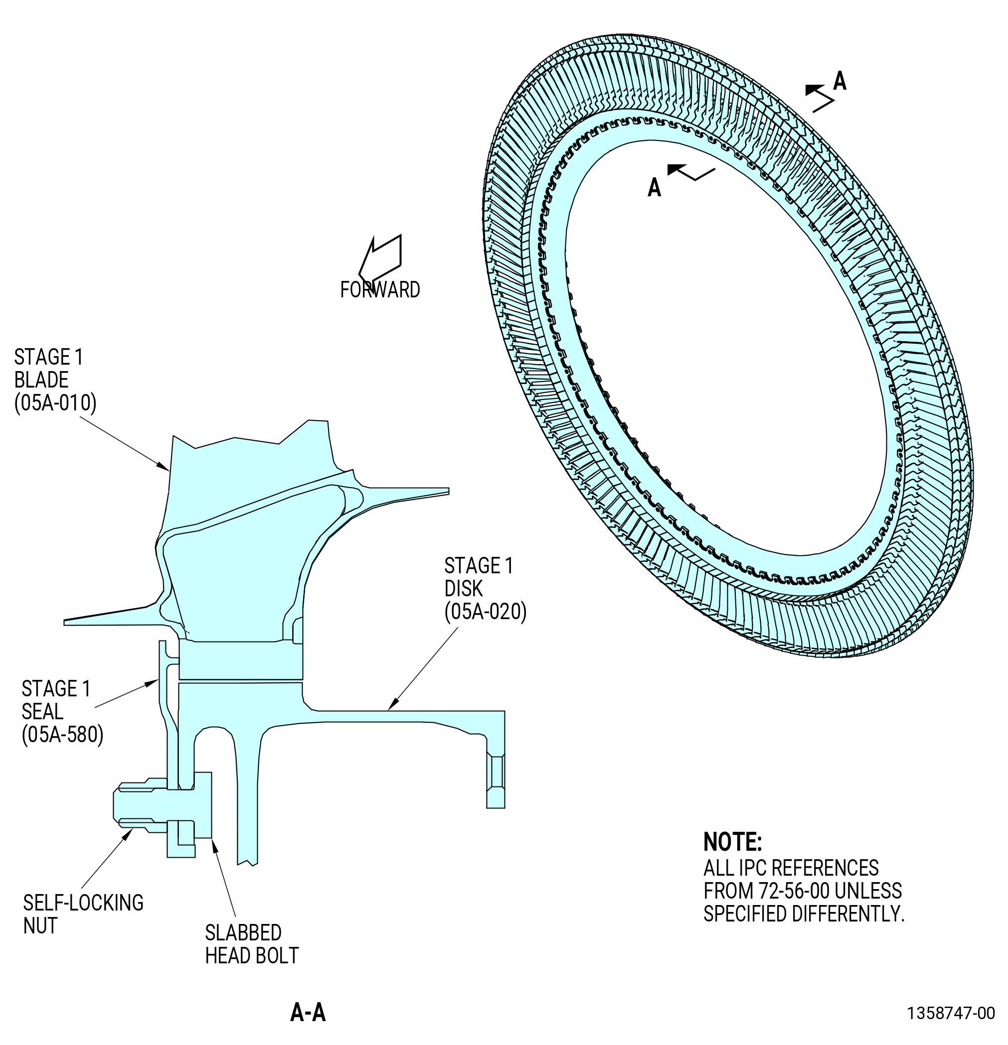
| (4) | Remove the stage 1 seal (05A-580) from the stage 1 disk as follows. Refer to Figure 532. |
| (a) | Remove the slabbed head bolts and self-locking nuts from the stage 1 disk and stage 1 seal. |
| (b) | Remove the stage 1 seal from the stage 1 disk. |
| Subtask 72-56-00-040-139 |
| W. | Disassemble the stage 1 disk and blade assembly as follows: |
| (1) | Use the 11C3541 LPT disk lift/turn fixture to put the stage 1 disk and blade assembly on the 11C3528 rotary table. Refer to Figure 504, Figure 530 and do as follows: |
| (a) | Install the lift arm (item 45) into the clevis (item 102) on the top lift cap (item 91) and insert the ball lock pin (item 25). |
| (b) | Attach an overhead hoist to the lift arm (item 45). |
| WARNING: |
|
| (c) | Lift the stage 1 disk and blade assembly. Lift high enough to install the second lift arm (item 45) on the bottom side of the spider (item 128). |
| (d) | Install the second lift cap (item 71) on the bottom side of the spider (item 128). |
| 1 | Put the lift cap (item 91) on the spider so the screws (item 27) go into the holes in the free positions of the spider (item 128). |
| 2 | Turn the lift cap CW until the pins are in the lock positions. |
| 3 | Insert the ball lock pin (item 24) to lock the lift cap (item 91) to the spider (item 128). |
| (e) | Install the second lift arm (item 45) in the clevis (item 102) on the second lift cap (item 71). Insert the ball lock pin (item 25). |
| (f) | Attach a second overhead hoist to the second lift arm (item 45). |
| (g) | Align the face of the lift arms (item 45) parallel to the plane of the hoists to make sure of a smooth rotation. |
| WARNING: |
|
| (h) | Lift the second lift arm (item 45) with the second overhead hoist to turn over the stage 1 disk and blade assembly. |
| (i) | Remove the first hoist from the first lift arm (item 45). |
| (j) | Remove the first ball lock pin (item 25), then remove the first lift arm (item 45). |
| (k) | Lower the stage 1 disk and blade assembly on the 11C3528 rotary table. |
| (l) | Put the blocks (item 7) on the table (item 5) so the blocks give support to the hub of the stage 1 disk. |
| (m) | Continue to lower the stage 1 disk and blade assembly and put it on the blocks (item 7). |
| CAUTION: |
|
| (2) | Tap the dovetails of the stage 1 blades (05A-010) with a Nylon drift or a non-metallic tool. Continue until the stage 1 blades are fully disengaged from the stage 1 disk. Do not hit the airfoils or you will damage the stage 1 blade. |
| CAUTION: |
|
| (3) | Remove the stage 1 blades (05A-010) from the stage 1 disk and put the blades in a safe location. |
| (4) | Lift the stage 1 disk (05A-020) from the 11C3528 rotary table with the 11C3541 LPT disk lift/turn fixture. |
| (a) | Install the lift arm (item 45) into the clevis (item 102) on the top lift cap (item 91). Install the ball lock pin (item 25). |
| (b) | Attach an overhead hoist to the lift arm (item 45). |
| WARNING: |
|
| (c) | Lift the stage 1 disk and blade assembly. Lift high enough to install the second lift arm (item 45) to the bottom side of the spider (item 128). |
| (d) | Install the second lift cap (item 71) on the bottom of the spider (item 128). |
| 1 | Put the lift cap on the spider so the screws (item 27) go into the holes in the free positions of the spider. |
| 2 | Turn the lift cap CW until the pins are in the lock positions. |
| 3 | Insert the ball lock pin (item 24) to lock the lift cap to the spider. |
| (e) | Install the second lift arm (item 45) into the clevis (item 102) on the second lift cap (item 71) and insert the ball lock pin (item 25). |
| (f) | Attach a second overhead hoist to the second lift arm (item 45). |
| (g) | Align the face of the lift arms (item 45) parallel to the plane of the hoists to make sure of a smooth rotation. |
| WARNING: |
|
| (h) | Lift the second lift arm (item 45) with the second hoist to turn over the stage 1 disk and blade assembly. |
| (i) | Remove the first hoist from the first lift arm (item 45). |
| (j) | Remove the first ball lock pin (item 24) then the first lift arm (item 45). |
| (k) | Put the stage 1 disk in a safe location. |
| (5) | Remove the 11C3541 LPT disk lift/turn fixture from the stage 1 disk. Refer to Figure 504 and do as follows. |
| (a) | Remove the ball lock pins (item 92) from one of the three legs of the spider (item 128). |
| (b) | Retract the lift bar (item 129). |
| WARNING: |
|
| (c) | Lift the 11C3541 LPT disk lift/turn fixture from the stage 1 disk. |
| Subtask 72-56-00-040-140 |
| X. | Disassemble the stage 2 disk (05A-120) and blade assembly as follows: |
| (1) | If necessary, remove the blocks (item 7) from the table (item 5) of the 11C3528 rotary table. Refer to Figure 533. |
| (2) | Prepare the 11C3541 LPT disk lift/turn fixture to lift the disk and blade assembly. Refer to Figure 504 and do as follows: |
| (a) | Install the set of feet marked for the correct stage into the lift bars (item 129) and insert the ball lock pins (item 93). |
| NOTE: |
|
| (b) | Install the bar/foot assemblies in the legs of the spider (item 128). |
| 1 | Adjust the positions of two of the lift bars (item 129) so the scribed lines for the correct stage align with the edges of the spider legs. |
| 2 | Insert the ball lock pins (item 92) to lock the two lift bars (item 129) to the spider. |
| 3 | Fully insert a third lift bar (item 129) in the third spider leg. |
| (3) | Install the 11C3541 LPT disk lift/turn fixture to the disk as follows: |
| (a) | Install the lift arm (item 45) into the clevis (item 102) and insert the ball lock pin (item 25). |
| (b) | Attach a hoist to the lift arm (item 45). |
| WARNING: |
|
| CAUTION: |
|
| (c) | Carefully lift the 11C3541 LPT disk lift/turn fixture and lower it in the bore of the disk. |
| (d) | Extend the third lift bar (item 129) that you inserted in the third spider leg. |
| 1 | Adjust the position of the lift bar so the scribed line for the correct stage aligns with the edge of the spider leg. |
| 2 | Lock the lift bar (item 129) in the spider (item 128) with the ball lock pins (item 92). |
| WARNING: |
|
| (4) | Lift the disk and blade assembly and put it forward side down on the 11C3528 rotary table. Refer to Figure 533. |
| (5) | Remove the overhead hoist from the lift arm (item 45) of the 11C3541 LPT disk lift/turn fixture. Refer to Figure 504. |
| (6) | Remove the ball lock pin (item 25), then remove the lift arm (item 45) from the clevis (item 102). |
| CAUTION: |
|
| (7) | Tap the dovetails of the blades with a Nylon drift or a non-metallic tool. Continue until the blades are fully disengaged from the disk. Do not hit the blades or you will damage them. |
| CAUTION: |
|
| (8) | Remove the blades from the stage 2 disk (05A-120) and put the blades in a safe location. |
| (9) | Install the lift arm (item 45) into the clevis (item 102) and insert the ball lock pin (item 25). |
| (10) | Attach an overhead hoist to the lift arm (item 45). |
| WARNING: |
|
| (11) | Lift the disk from the 11C3528 rotary table and put the disk in a safe location. |
| (12) | Remove the 11C3541 LPT disk lift/turn fixture from the disk and blade assembly. Refer to Figure 504 and do as follows: |
| (a) | Remove the ball lock pins (item 92) from one of the three legs of the spider (item 128). |
| (b) | Retract the lift bar (item 129). |
| WARNING: |
|
| CAUTION: |
|
| (c) | Lift the 11C3541 LPT disk lift/turn fixture from the disk. |
| (13) | Remove the blocks (item 7) of the 11C3528 rotary table from the table (item 5). Refer to Figure 533. |
| Subtask 72-56-00-040-141 |
| CAUTION: |
|
| CAUTION: |
|
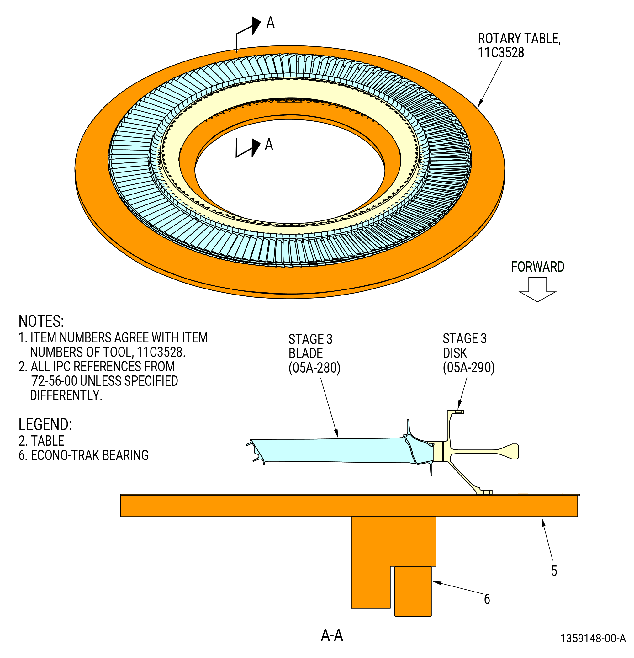
| Y. | Continue to disassemble the stages 3 through 7 disk and blade assemblies. Refer to the procedure above for the stage 2 disk (05A-120) and blade assembly. Refer to Figure 534 through Figure 538. |
| NOTE: |
|
| Subtask 72-56-00-040-142 |
| Z. | Remove the LPT case (01-012) from the 11C3520 buildup stand and install on the 11C3506 buildup/transport/storage stand as follows: |
| (1) | Attach the 11C3530 lift fixture to the LPT case (01-012) as follows. Refer to Figure 539. |
| (a) | Attach the sling assembly (item 12) to an overhead hoist hook. |
| (b) | Turn the pin (item 4) counterclockwise (CCW) to remove the pin from the hook blocks (item 10). |
| CAUTION: |
|
| (c) | Attach the hook blocks (item 10) at three equal locations to the aft outer flange of the LPT case (01-012). You must turn the pin (item 4) CW to attach the hook blocks (item 10) to the LPT case. |
| WARNING: |
|
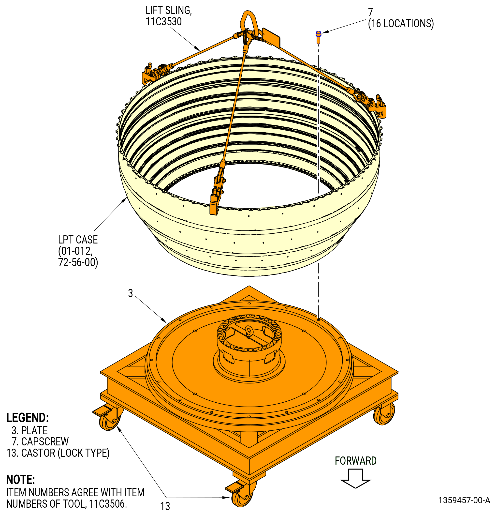
| (2) | Lift the LPT case (01-012) with the 11C3530 lift fixture and put the LPT case on the 11C3506 build stand as follows: |
| CAUTION: |
|
| (a) | Put the LPT case (01-012), forward end down, onto the 11C3506 buildup/transport/storage stand as follows. Refer to Figure 540. |
| 1 | Lock the castors (item 13) to prevent movement of the buildup/transport/storage stand. |
| 2 | Lower the LPT case (01-012) onto the plate (item 3). |
| 3 | Attach the LPT case (01-012) to the plate (item 3) with capscrews (item 7) at 16 locations. |