| GENX-1B ENGINE MANUAL | Dated: 11/24/2023 | |
| EM 72-57-00 , DISASSEMBLY 001 | ||
| TURBINE REAR FRAME ASSEMBLY - DISASSEMBLY 001 | ||
| GENX-1B ENGINE MANUAL | Dated: 11/24/2023 | |
| EM 72-57-00 , DISASSEMBLY 001 | ||
| TURBINE REAR FRAME ASSEMBLY - DISASSEMBLY 001 | ||
| * * * FOR ALL |
| TASK 72-57-00-040-801 |
| 1 . | General. |
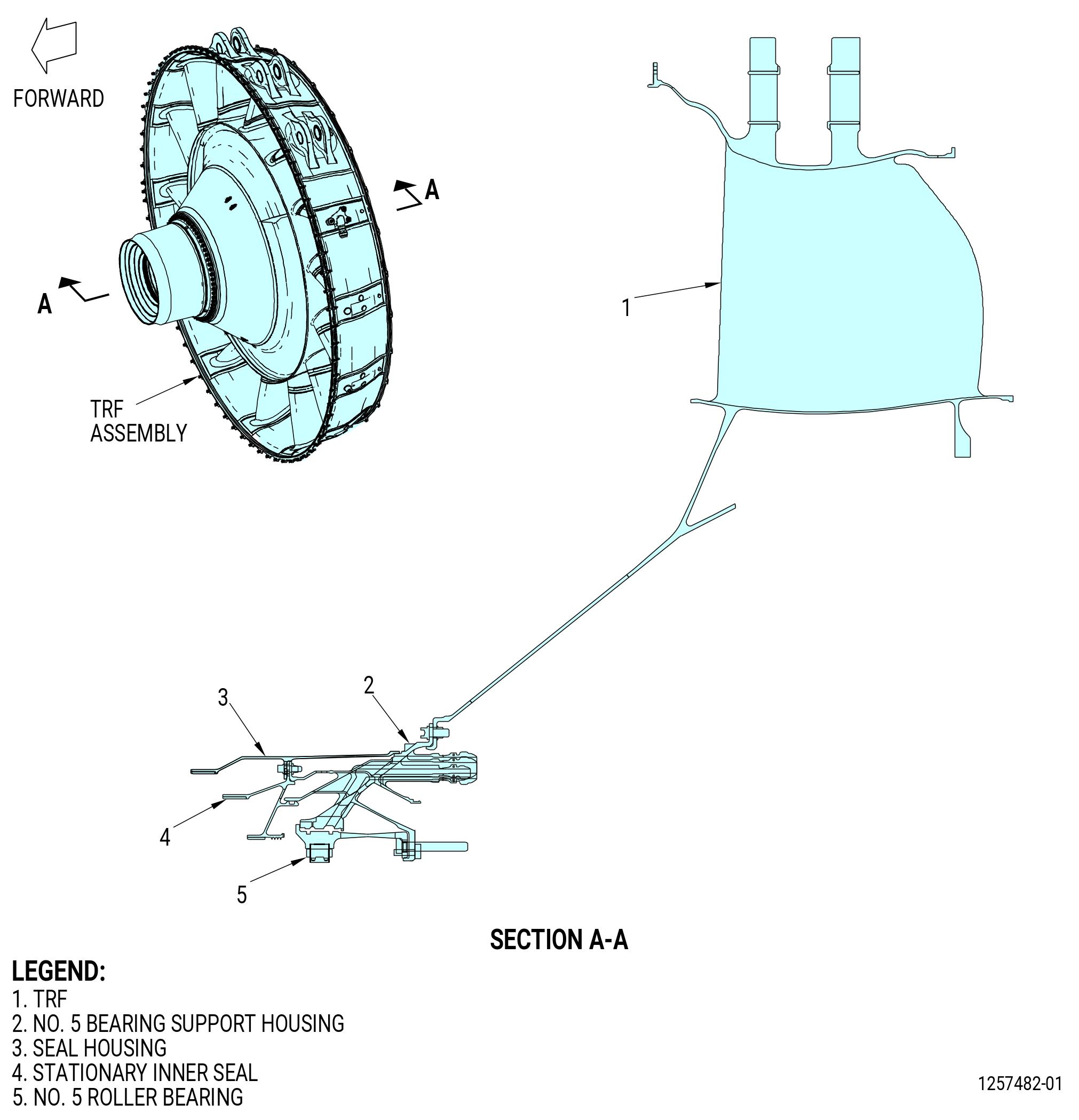
| A. | This procedure gives instructions to disassemble the turbine rear frame (TRF) assembly. Refer to Figure 501. |
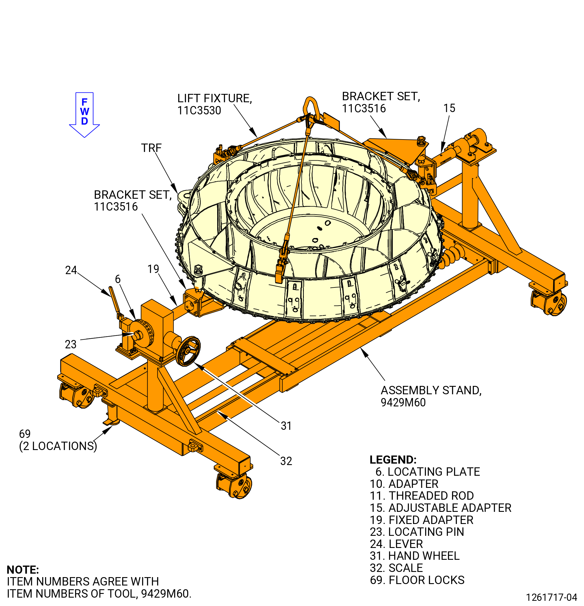
| B. | The TRF assembly is installed on the 9429M60 assembly stand. Refer to TASK 72-00-04-030-801 (72-00-04, Disassembly 001) and Figure 502. |
| C. | Protective covers must be installed on spare assemblies only. |
| 2 . | Tools, Equipment, and Materials. |
| NOTE: |
|
| A. | Tools and Equipment. |
| (1) | Special Tools. |
| (2) | Standard Tools and Equipment. None. |
| (3) | Locally Manufactured Tools. None. |
| B. | Consumable Materials. |
|
| C. | Referenced Procedures. |
|
| D. | Expendable Parts. None. |
| 3 . | Procedure. |
| Subtask 72-57-00-040-016 |
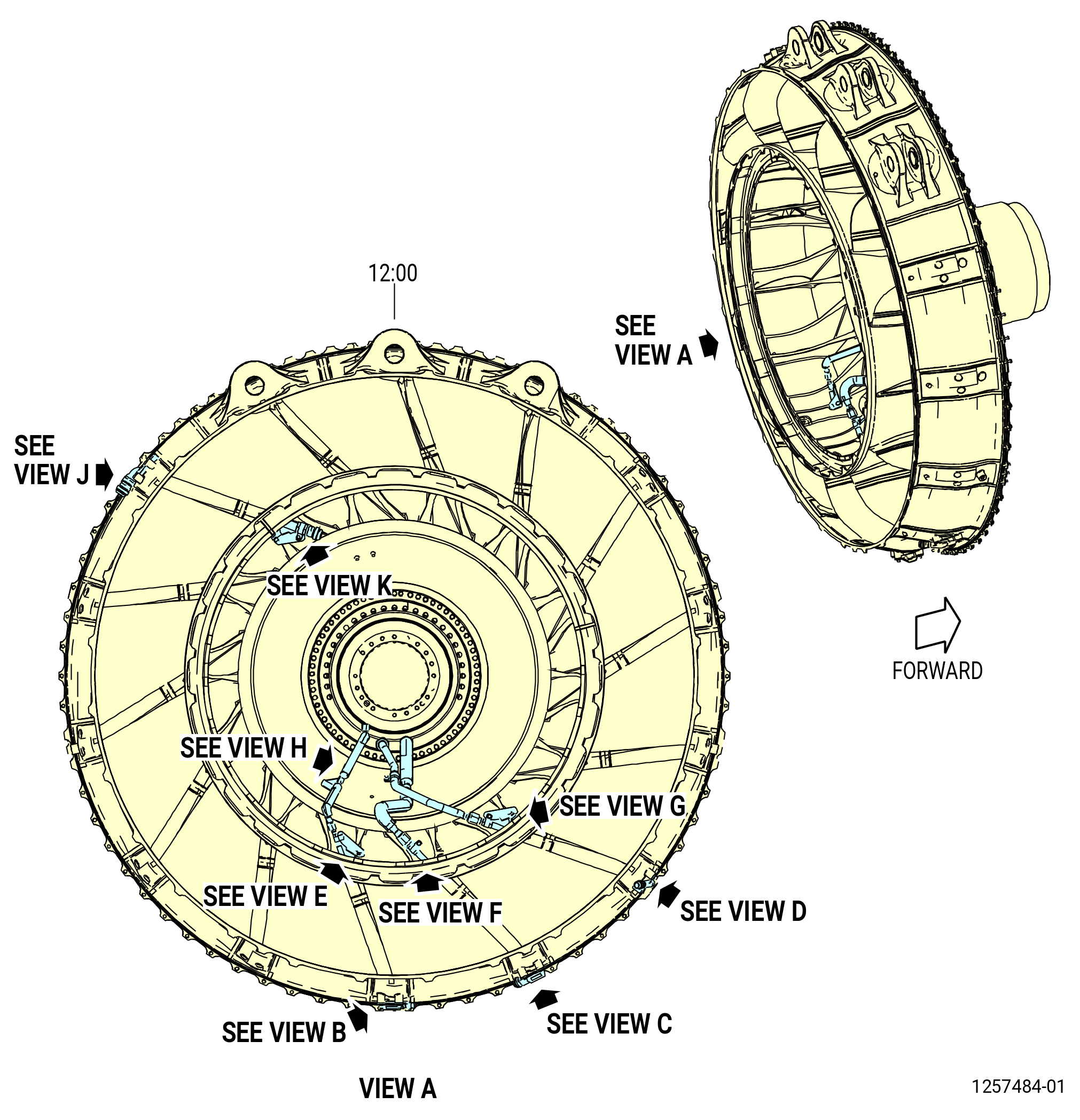
| A. | Remove the supply connector tube from the fitting on the tube that extends inboard from the No. 8 strut, and the fitting on the No. 5 bearing support housing as follows. Refer to Figure 503. |
| NOTE: |
|
| (1) | Turn the TRF assembly to the horizontal position with the 9429M60 assembly stand as follows. Refer to Figure 502. |
| CAUTION: |
|
| (a) | Lower the floor locks (item 69) of the 9429M60 assembly stand until they touch the floor. The floor locks must stay in contact with the floor to prevent movement of the roll-over stand. Make sure that the roll-over stand is level. |
| CAUTION: |
|
| (b) | Move and hold the lever (item 24) of the 9429M60 assembly stand to disengage the locating pin (item 23) from the hole in the locating plate (item 6). |
| (c) | Turn the hand wheel (item 31) to turn the TRF assembly to the horizontal position. |
| (d) | Move the lever (item 24) to engage the locating pin (item 23) with the hole in the locating plate (item 6). |
| (2) | Remove the bolt, nut, and loop clamp that attach the supply connector tube to the bracket. |
| (3) | Remove the safety wire or safety cable from the B-nut of the No. 5 bearing support housing and from the swivel nut on the end of the oil supply tube. |
| (4) | Loosen the B-nuts on the two sides of the oil supply connector tube. |
| (5) | Remove the supply connector tube. |
| (6) | Remove the nuts, washers, bolts, and bracket from the TRF. |
| Subtask 72-57-00-040-014 |
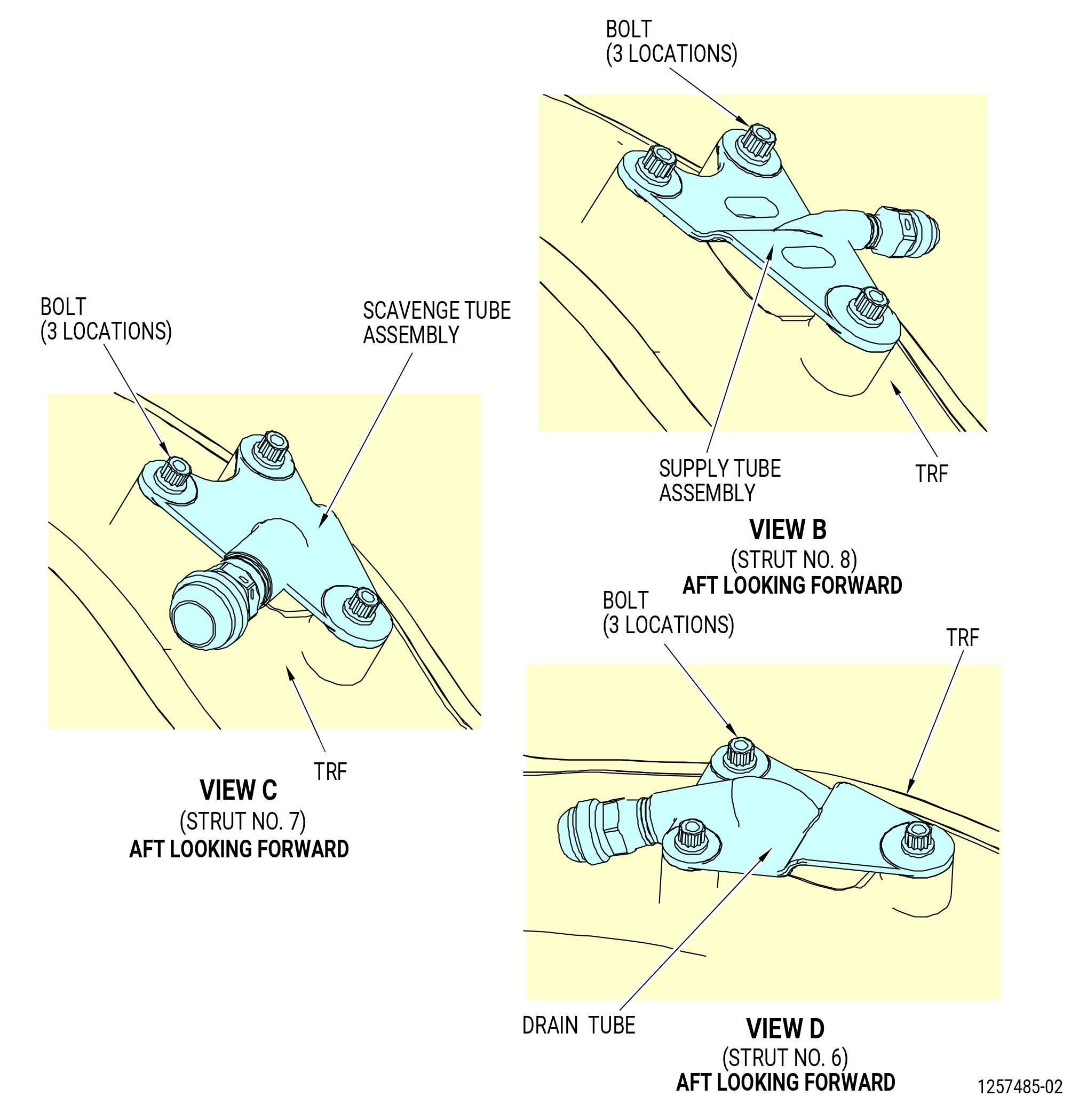
| B. | Remove the supply tube from the No. 8 strut as follows. Refer to Figure 503. |
| NOTE: |
|
| (1) | Remove the self-locking nut (nut) (01-220) (SIN 443K2), washer, bolt, and loop clamp that attach the supply tube to the bracket. Discard the nut. |
| (2) | Remove the bolts that attach the supply tube flange to the TRF. |
| (3) | Remove the supply tube assembly. |
| (4) | Remove the self-locking nut (nut) (01-300) (SIN 443K0), washer, bolt, and bracket from the TRF. Discard the nut. |
| Subtask 72-57-00-040-020 |
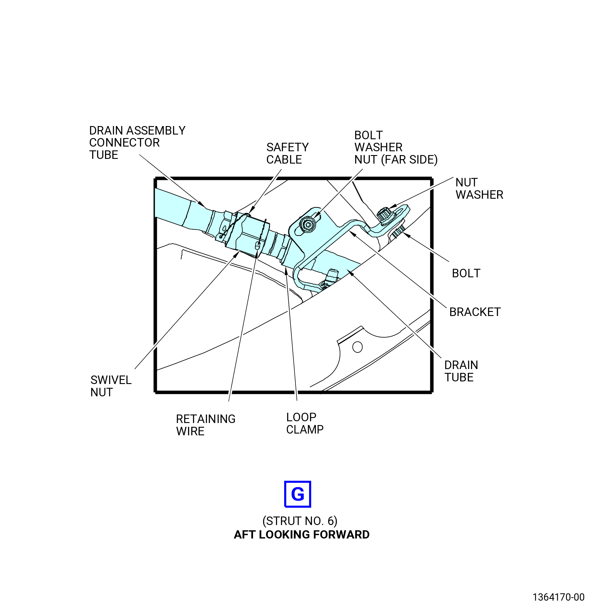
| C. | Remove the drain connector tube from the fitting on the tube that extends inboard from the No. 6 strut, and the fitting on the No. 5 bearing support housing. Refer to Figure 503. |
| NOTE: |
|
| (1) | Remove the nut, bolt, and loop clamp that attach the drain connector tube to the bracket. |
| (2) | Remove the safety wire or safety cable from the B-nut of the No. 5 bearing support housing. Remove the swivel nut on the end of the drain tube. |
| (3) | Loosen the B-nut and the swivel nut. |
| (4) | Remove the drain connector tube. |
| Subtask 72-57-00-030-001 |
| D. | Remove the drain tube from the No. 6 strut as follows. Refer to Figure 503. |
| NOTE: |
|
| (1) | Remove the self-locking nut (nut) (01-580) (SIN 458K1), washers, bolt, and loop clamp that attach the drain tube to the bracket. Discard the nut. |
| (2) | Remove the safety wire or safety cable that safety the swivel wire to the swivel nut. |
| (3) | Remove the retaining wire (01-555) (SIN 45898) and the swivel nut from the drain tube. Discard the retaining wire. |
| NOTE: |
|
| (4) | Remove the bolts that attach the drain tube flange to the TRF. |
| (5) | Remove the drain tube assembly. |
| (6) | Remove the self-locking nut (nut) (01-620) (SIN 458K0), washer, bolt, and bracket from the TRF. Discard the nut. |
| Subtask 72-57-00-040-015 |
| E. | Remove the scavenge connector tube from the fitting on the tube that extends inboard from the No. 7 strut, and the fitting on the No. 5 bearing support housing as follows. Refer to Figure 503. |
| NOTE: |
|
| (1) | Remove the nut, bolt, and loop clamp that attach the scavenge connector tube to the bracket. |
| (2) | Remove the safety wire or safety cable from the B-nut of the No. 5 bearing support housing, and swivel nut on the end of the scavenge connector tube. |
| (3) | Loosen the B-nut and the swivel nut. |
| (4) | Remove the scavenge connector tube. |
| (5) | Remove the bolts and bracket from the TRF. |
| Subtask 72-57-00-030-002 |
| F. | Remove the scavenge tube from the No. 7 strut as follows. Refer to Figure 503. |
| (1) | Remove the self-locking nut (nut) (01-440) (SIN 452K1), washers, bolt, and loop clamp that attach the scavenge tube to the bracket. Discard the nut. |
| (2) | Remove the safety wire or safety cable from swivel wire and from the swivel nut. |
| (3) | Remove the retaining wire (01-365) (SIN 45298) and the swivel nut from the scavenge tube. Discard the retaining wire. |
| NOTE: |
|
| (4) | Remove the bolts that attach the scavenge tube flange to the TRF. |
| (5) | Remove the scavenge tube assembly. |
| (6) | Remove the self-locking nut (nut) (01-480) (SIN 452K0), washer, bolt, and bracket from the TRF. Discard the nut. |
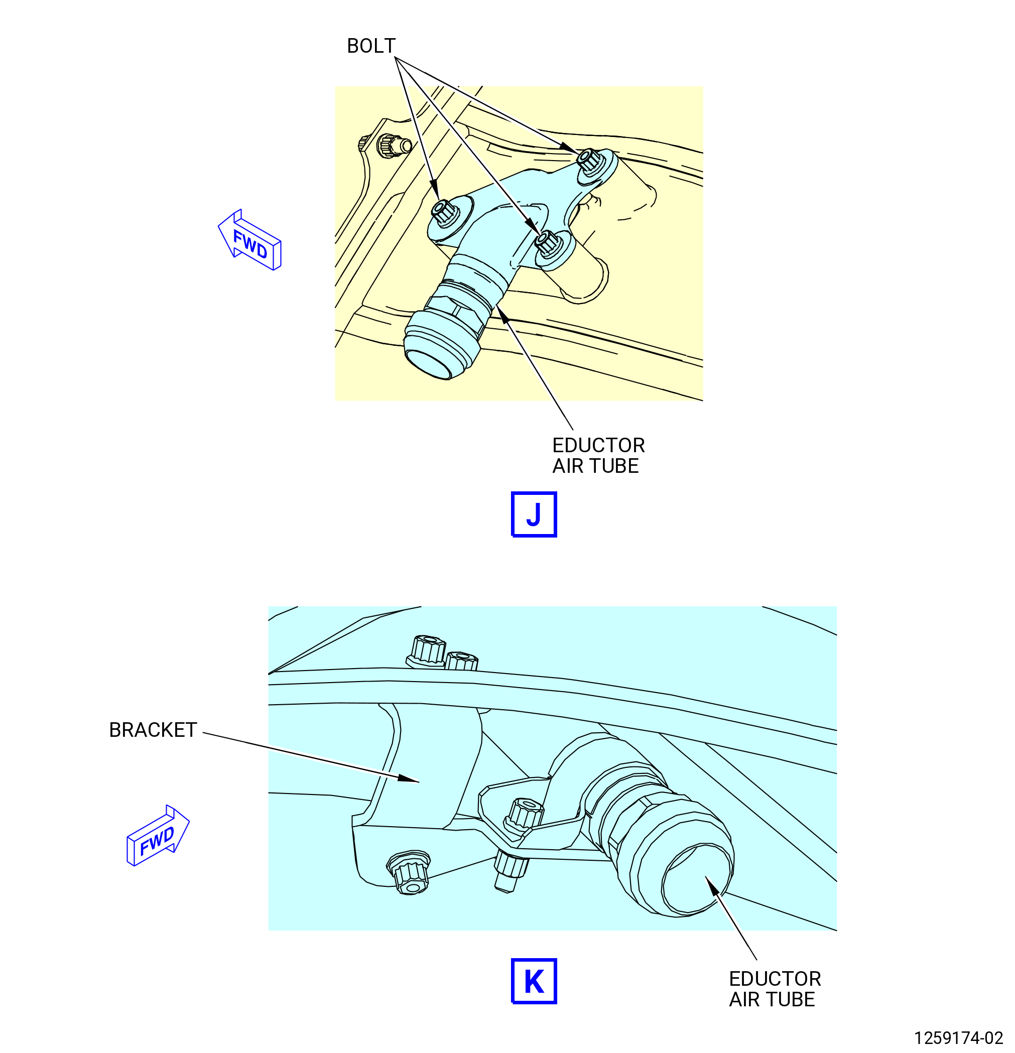
| G. | Put caps on the open ends of the air eductor tube assembly located at the strut No. 11 in the TRF at the 10:00 o'clock position, ALF. Refer to Figure 503. |
| Subtask 72-57-00-030-003 |
| H. | Deleted. |
| Subtask 72-57-00-040-009 |
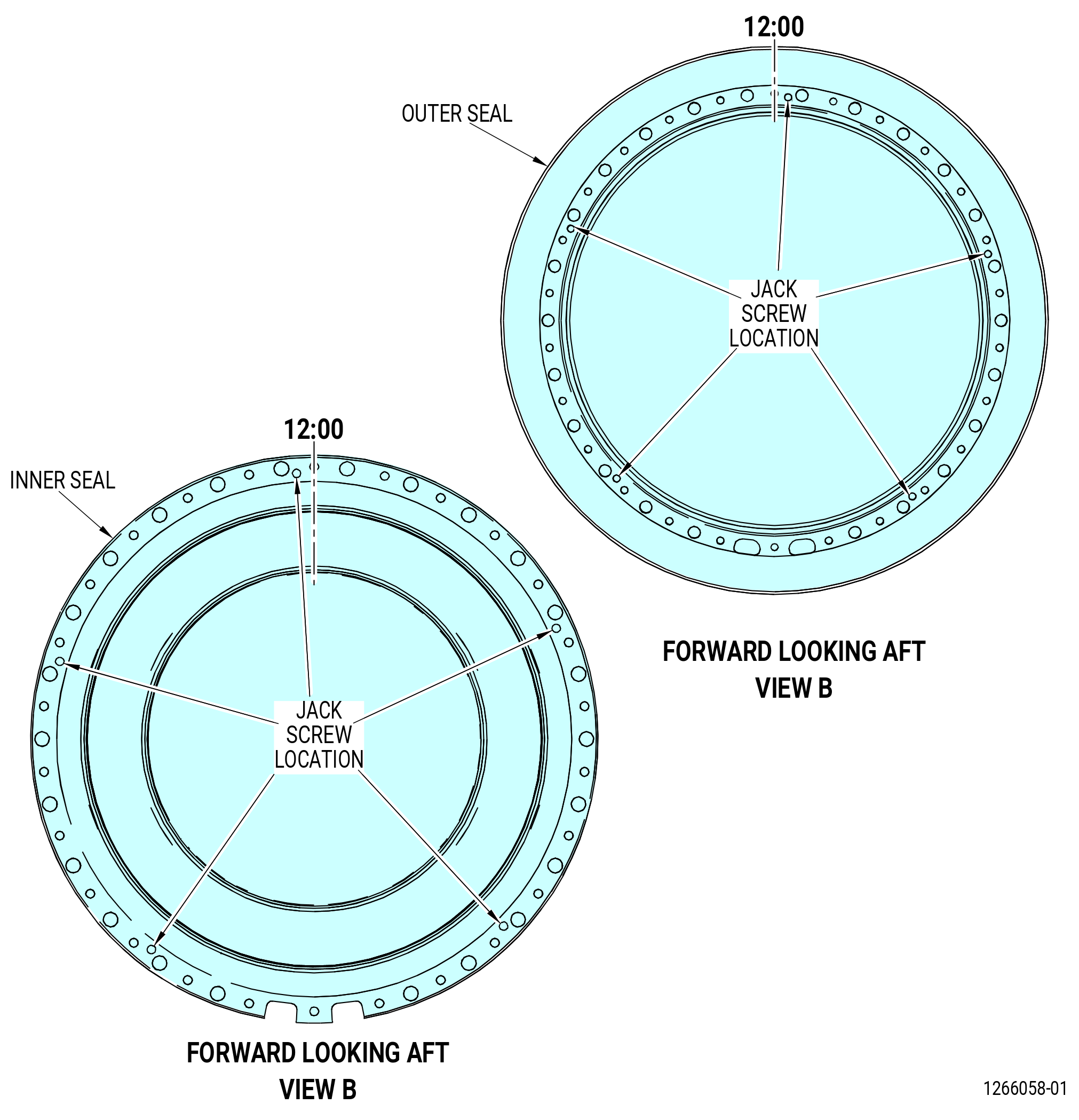
| I. | Remove the No. 5 bearing outer stationary seal (outer seal) and inner stationary seal (inner seal) from the No. 5 bearing support housing as follows. Refer to Figure 504. |
| CAUTION: |
|
| (1) | Turn the TRF assembly 180 degrees, with the 9429M60 assembly stand, as follows. Refer to Figure 502. |
| CAUTION: |
|
| (a) | Lower the floor locks (item 69) of the 9429M60 assembly stand until they touch the floor. The floor locks must stay in contact with the floor to prevent movement of the roll-over stand. Make sure that the roll-over stand is level. |
| CAUTION: |
|
| (b) | Move and hold the lever (item 24) of the 9429M60 assembly stand to disengage the locating pin (item 23) from the hole in the locating plate (item 6). |
| (c) | Turn the hand wheel (item 31) to turn the TRF assembly to the horizontal position. |
| (d) | Move the lever (item 24) to engage the locating pin (item 23) with the hole in the locating plate (item 6). |
| (2) | Remove the bolts that attach the outer seal and the inner seal to the No. 5 bearing support housing. |
| (3) | Remove the outer and inner seals from the No. 5 bearing support housing with five jack screws (0.250-28 UNF-2A). |
| (4) | Remove and discard the preformed packing (01-150) (SIN 01552) from the inner seal. |
| Subtask 72-57-00-040-011 |
| CAUTION: |
|
| J. | Remove the No. 5 bearing support housing from the TRF and install it on the 11C3543 buildup fixture as follows: |
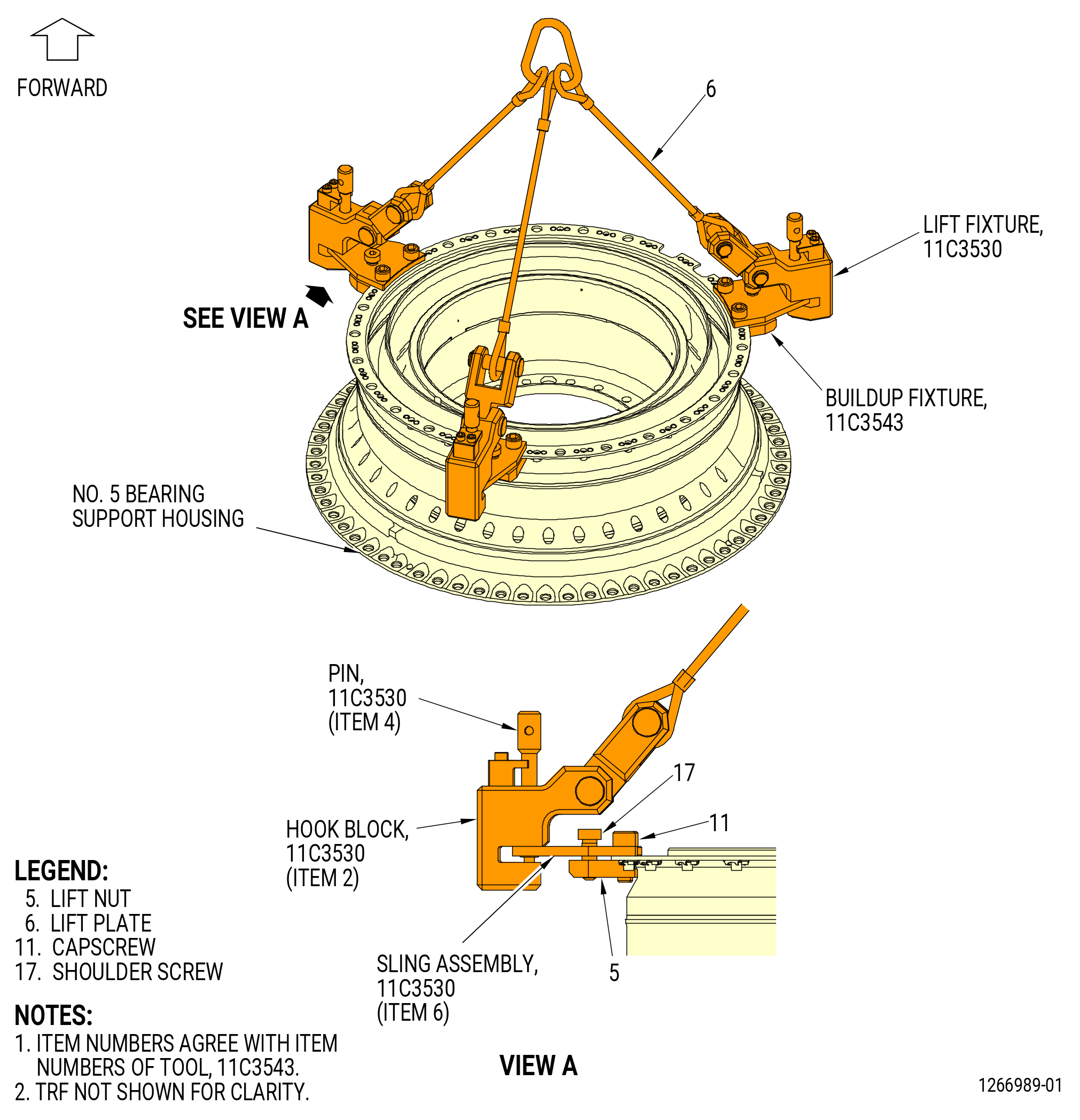
| (1) | Install the 11C3530 lift fixture to the No. 5 bearing support housing as follows. Refer to Figure 505. |
| (a) | Install the lift plates (item 6) of the 11C3543 buildup fixture on the No. 5 bearing support housing as follows. |
| 1 | Loosen the screws (item 17) to give a sufficient gap between the lift plates (item 6) and the lift nuts (item 5). |
| 2 | Put the lift plates (item 6) on the forward bolt flange of the No. 5 bearing support housing at three equally spaced locations. |
| a | Put the lift plates (item 6) on the forward side and the lift nuts (item 5) on the aft side of the forward bolt flange. |
| 3 | Attach the lift plates (item 6) and lift nuts (item 5) to the forward bolt flange of the No. 5 bearing support housing with the cap screws (item 11). |
| (b) | Loosen the pins (item 4) of the 11C3530 lift fixture and pull them out from the hook blocks (item 2). |
| (c) | Install the hook blocks (item 2) to the lift plates (item 6) of the 11C3543 buildup fixture that are installed on the forward bolt flange of the No. 5 bearing support housing. |
| (d) | Install the pins (item 4) of the 11C3530 lift fixture into the hook blocks (item 2). Tighten the pins by hand. |
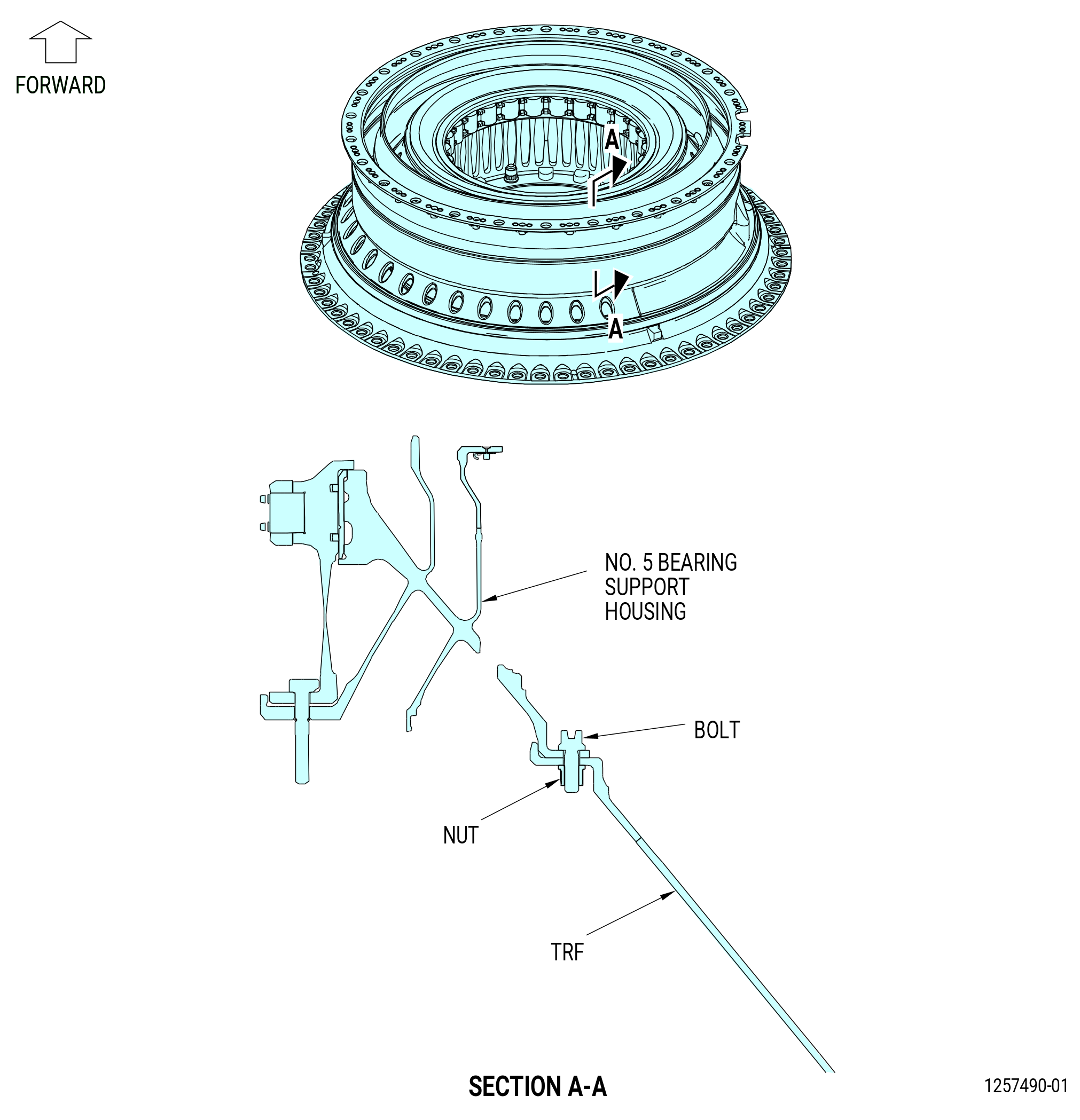
| (2) | Remove the self-locking nuts (nuts) (01-070) (SIN 01541) and the bolts that attach the No. 5 bearing support housing to the TRF. Discard the nut. Refer to Figure 506. |
| WARNING: |
|
| (3) | If necessary, use a heat gun to apply heat to the aft outer bolt flange of the No. 5 bearing support housing for 15 minutes. |
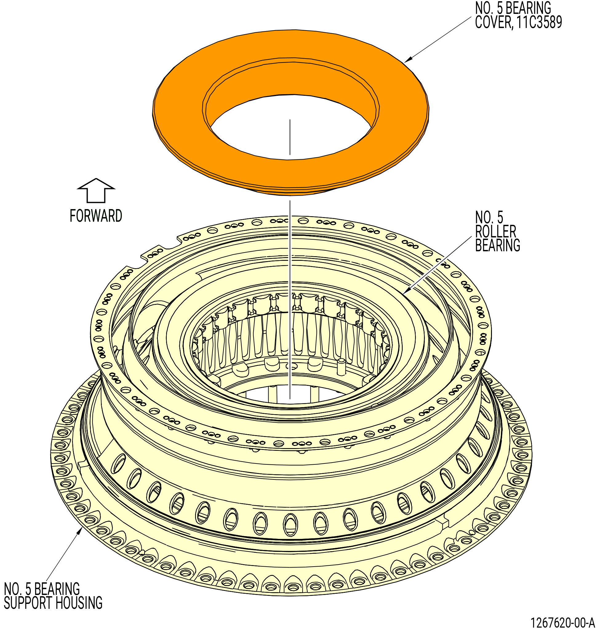
| (4) | Put the 11C3589 No. 5 bearing cover on the No. 5 bearing. Refer to Figure 507. |
| WARNING: |
|
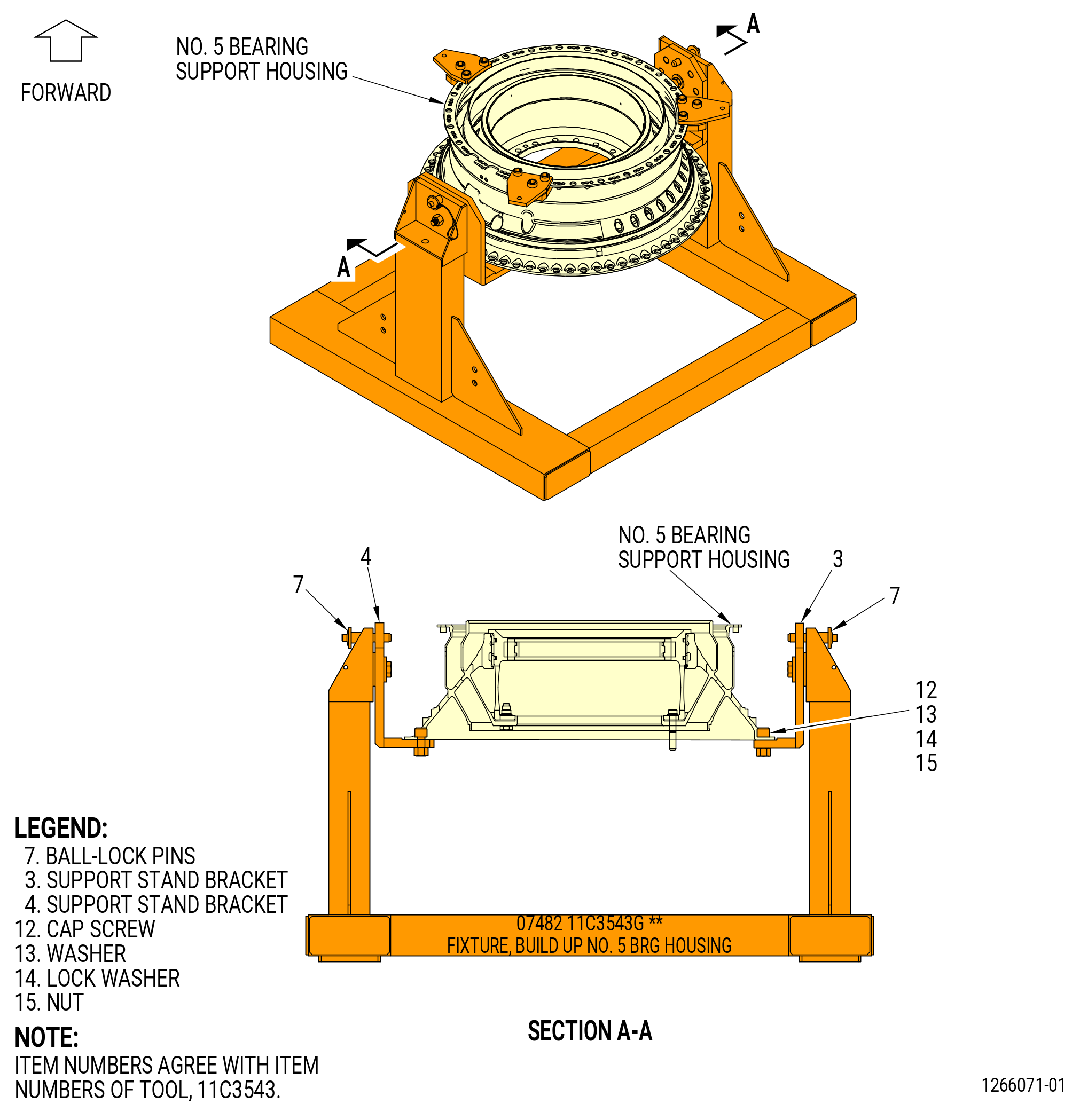
| (5) | Lift the No. 5 bearing support housing from the TRF with the sling assembly (item 6) and install it on the 11C3543 buildup fixture as follows. Refer to Figure 508. |
| (a) | Put the No. 5 bearing support housing on the support stand brackets (items 3 and 4). |
| (b) | Attach the No. 5 bearing support housing to the support stand brackets with the cap screws (item 12), washers (items 13), lock washers (item 14), and nuts (item 15). |
| Subtask 72-57-00-040-022 |
| K. | Remove the 11C3530 lift fixture from the No. 5 bearing support housing as follows. Refer to Figure 505. |
| (1) | Turn the pins (item 4) counterclockwise (CCW) and disengage them from the hook blocks (item 2). |
| (2) | Remove the hook blocks (item 2) from the housing flange. |
| WARNING: |
|
| (3) | Lift the 11C3530 lift fixture from the No. 5 bearing support housing and store in a safe location. |
| Subtask 72-57-00-040-013 |
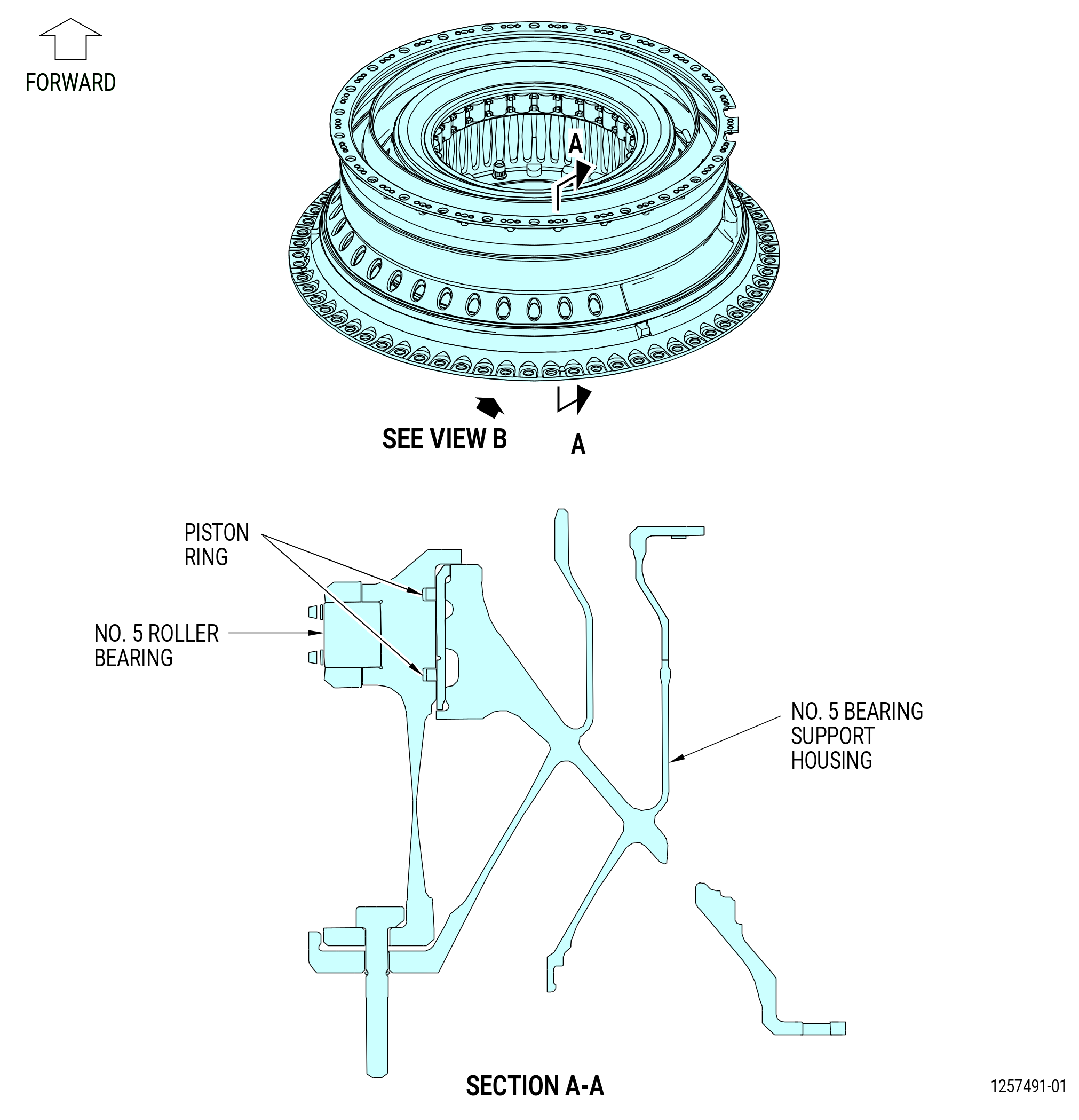
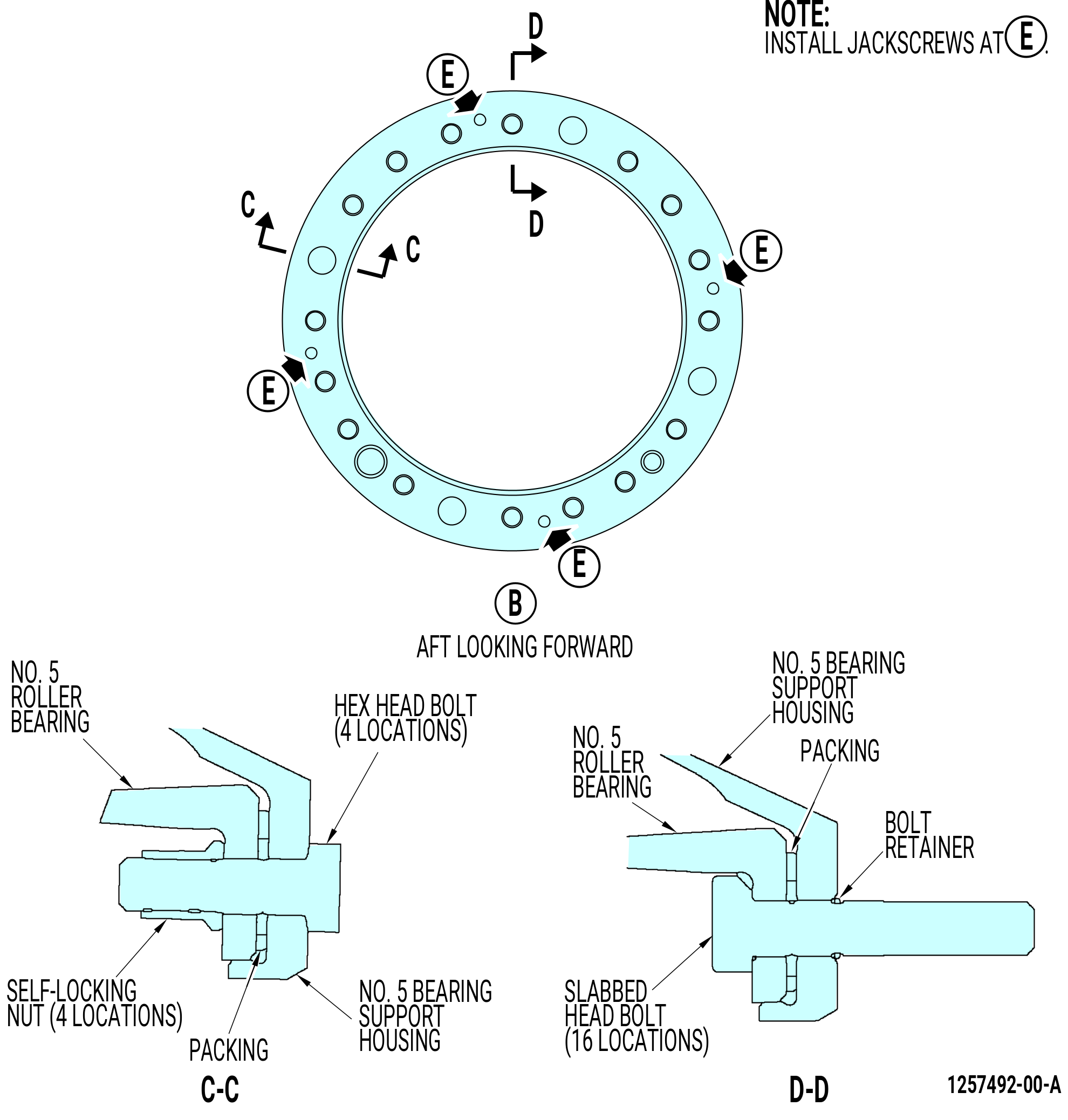
| L. | Remove the No. 5 roller bearing from the No. 5 bearing support housing as follows. Refer to Figure 509. |
| CAUTION: |
|
| (1) | Remove the self-locking nuts and the hex head bolts that attach the No. 5 roller bearing to the No. 5 bearing support housing. |
| (2) | Turn the No. 5 bearing support housing to the aft end up position as follows: |
| (a) | Remove the ball lock pins (item 7). |
| (b) | Turn the No. 5 bearing support housing to the vertical position, aft end up. |
| (c) | Install the ball lock pins (item 7) to lock the support stand brackets (items 3 and 4). |
| (3) | Remove the bolt retainers and the slabbed head bolts from the No. 5 bearing support housing and No. 5 roller bearing. Discard the bolt retainers (01-100) (SIN 01594). |
| (4) | Remove the No. 5 roller bearing from the No. 5 bearing support housing. Use four jackscrews (0.250-28 UNF-2A). |
| (5) | Remove the piston rings from the No. 5 roller bearing. |
| (6) | Remove the packing from the No. 5 bearing support housing. Discard the packing (01-130) (SIN 01556) or (01-131) (SIN 01556). |
| (7) | Put a waterproof material cover on the No. 5 roller bearing. |
| Subtask 72-57-00-040-023 |
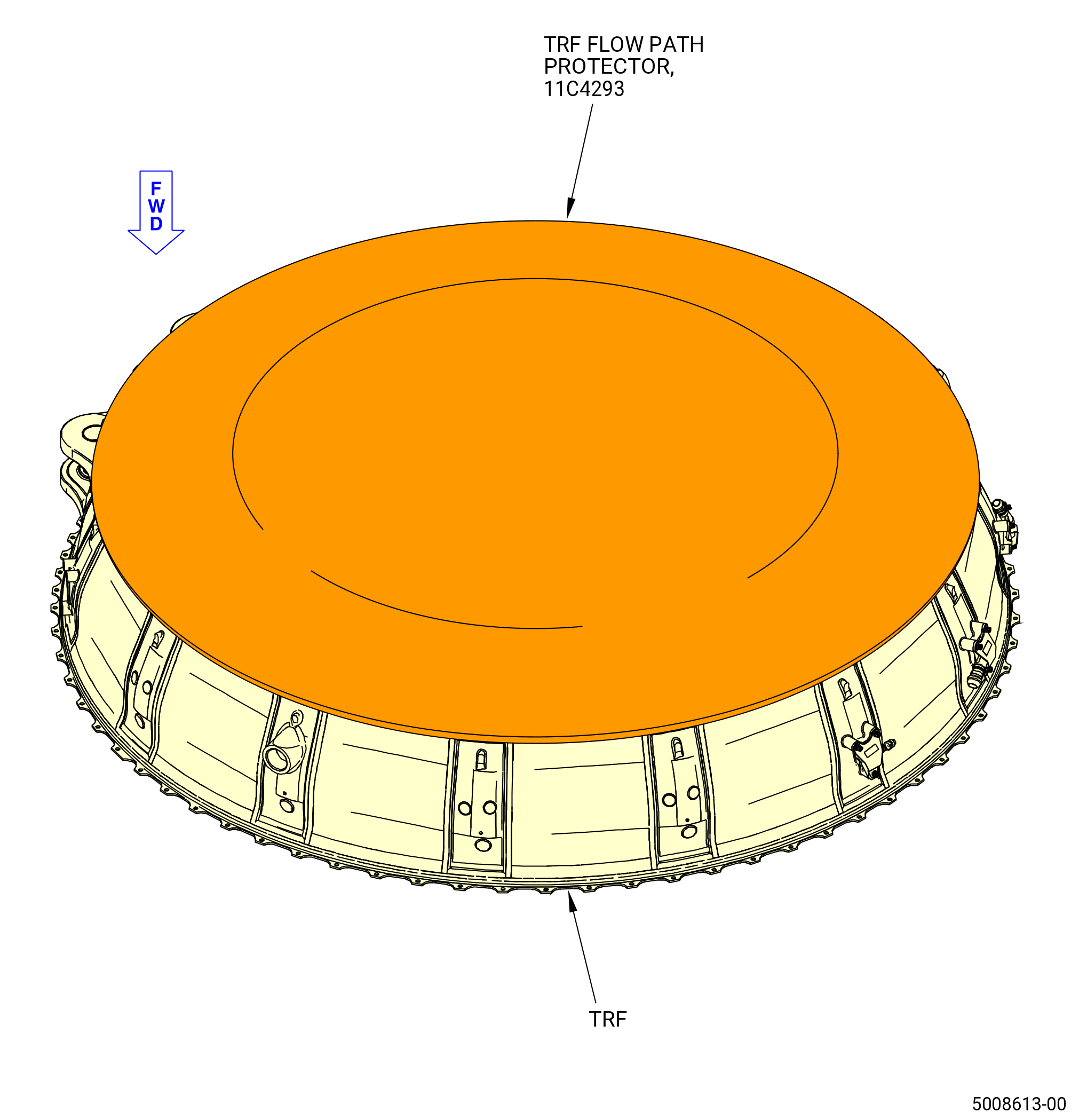
| M. | Install the 11C4293 TRF flow path protector on the aft side of the TRF. Refer to Figure 510. |