| GENX-1B ENGINE MANUAL | Dated: 02/26/2020 | |
| EM 72-58-00 , DISASSEMBLY 001 | ||
| MID FAN SHAFT ASSEMBLY - DISASSEMBLY 001 CONFIGURATION 02 | ||
| GENX-1B ENGINE MANUAL | Dated: 02/26/2020 | |
| EM 72-58-00 , DISASSEMBLY 001 | ||
| MID FAN SHAFT ASSEMBLY - DISASSEMBLY 001 CONFIGURATION 02 | ||
| * * * FOR 1B/P/G04.1B/P1/G01.ALL PIP 2 |
| TASK 72-58-00-030-802 |
| 1 . | General. |
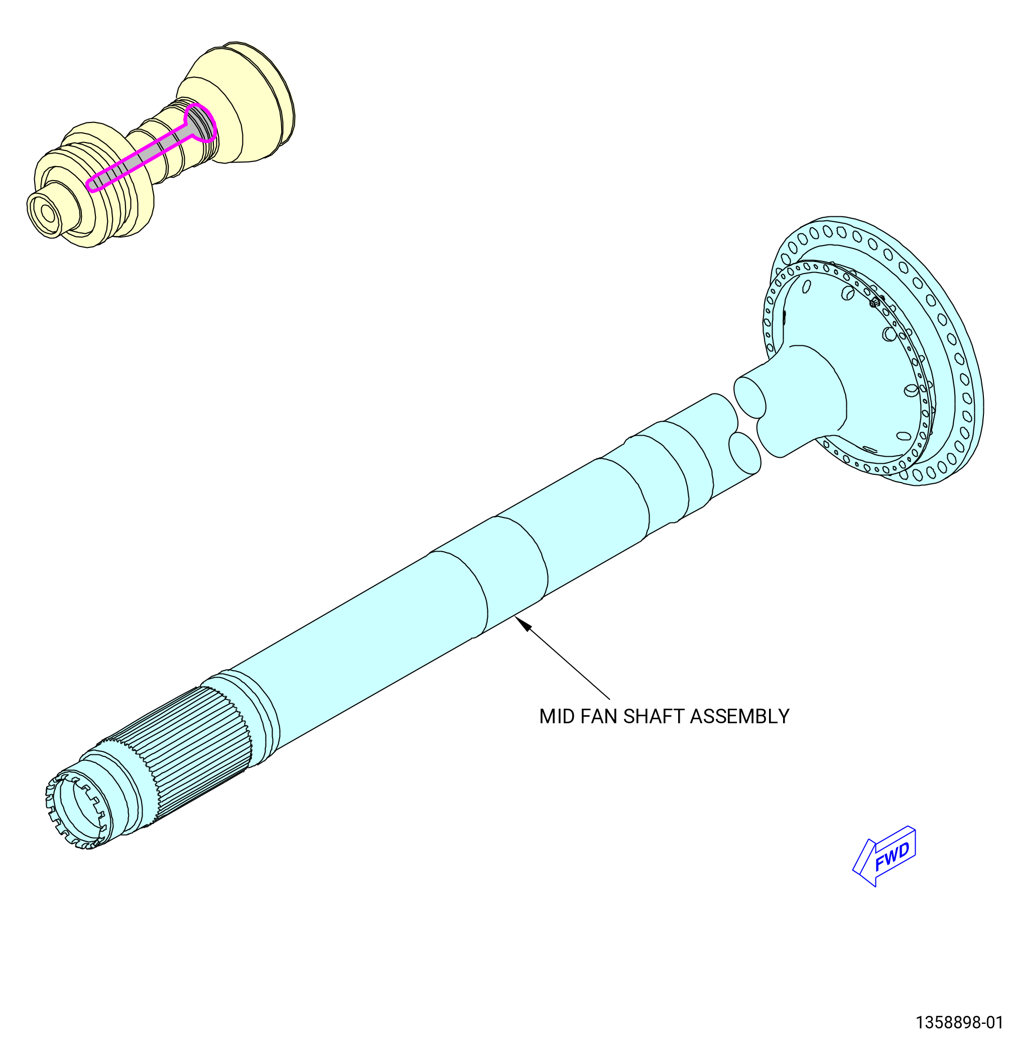
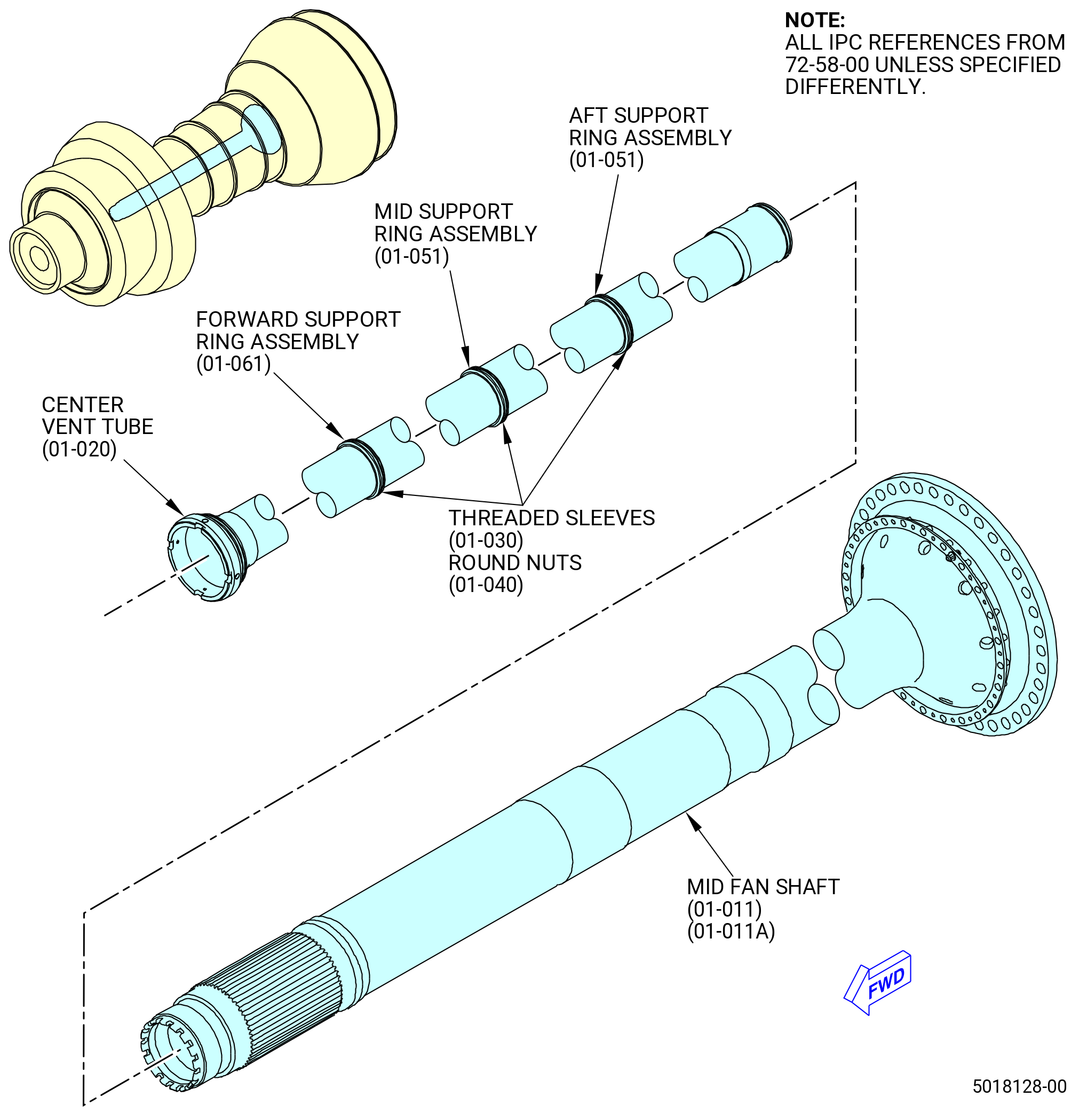
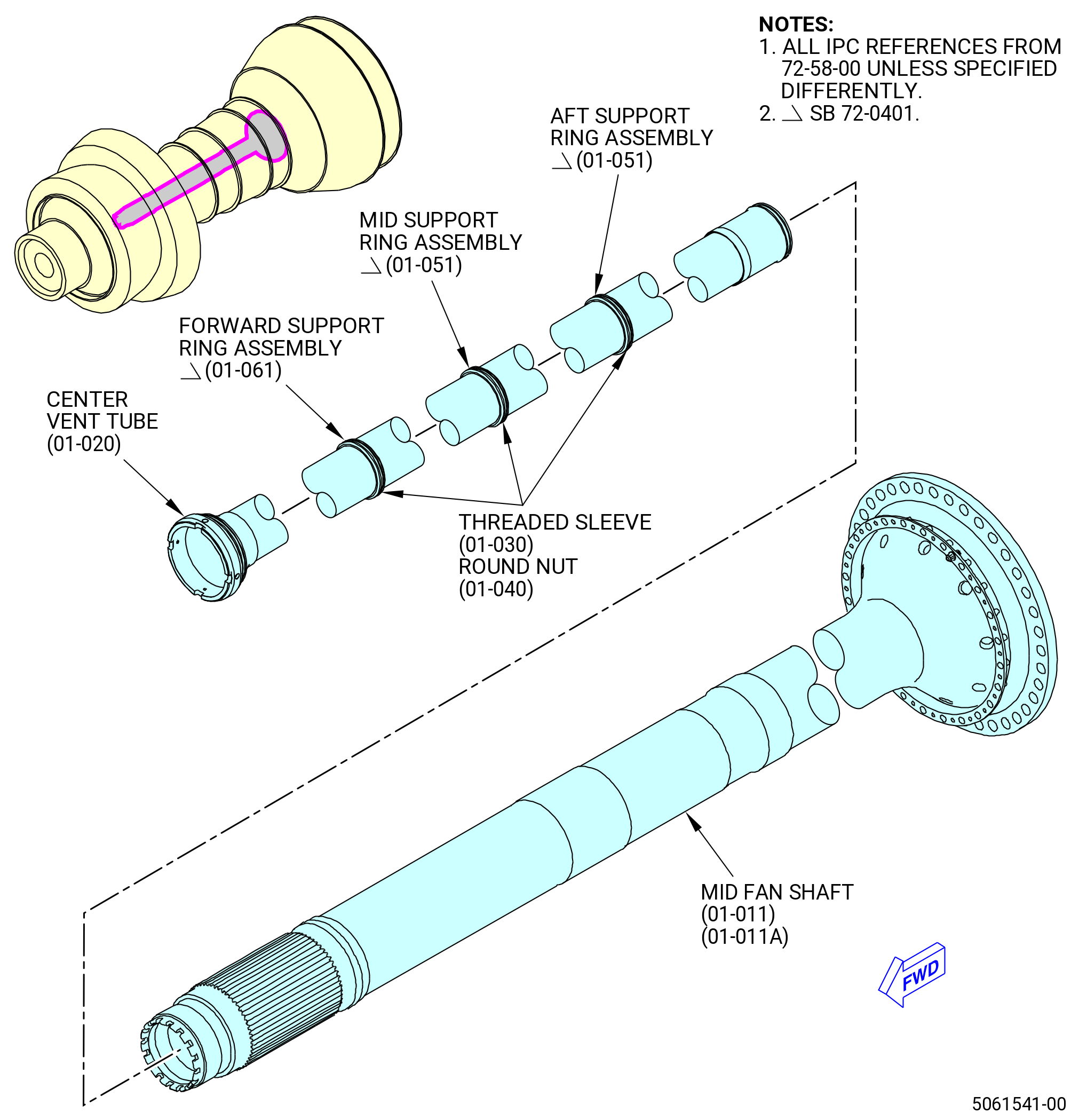
| A. | This procedure gives instructions to disassemble the mid fan shaft assembly for SB 72-0040 (without or with SB 72-0114 implemented to SB 72-0040 engines). Refer to Figure 501. |
| Mid fan shaft assembly: |
| • |
|
| • |
|
| Mid fan shaft: |
| • |
|
| • |
|
| • |
|
| • |
|
| • |
|
| • |
|
| • |
|
| • |
|
| NOTE: |
|
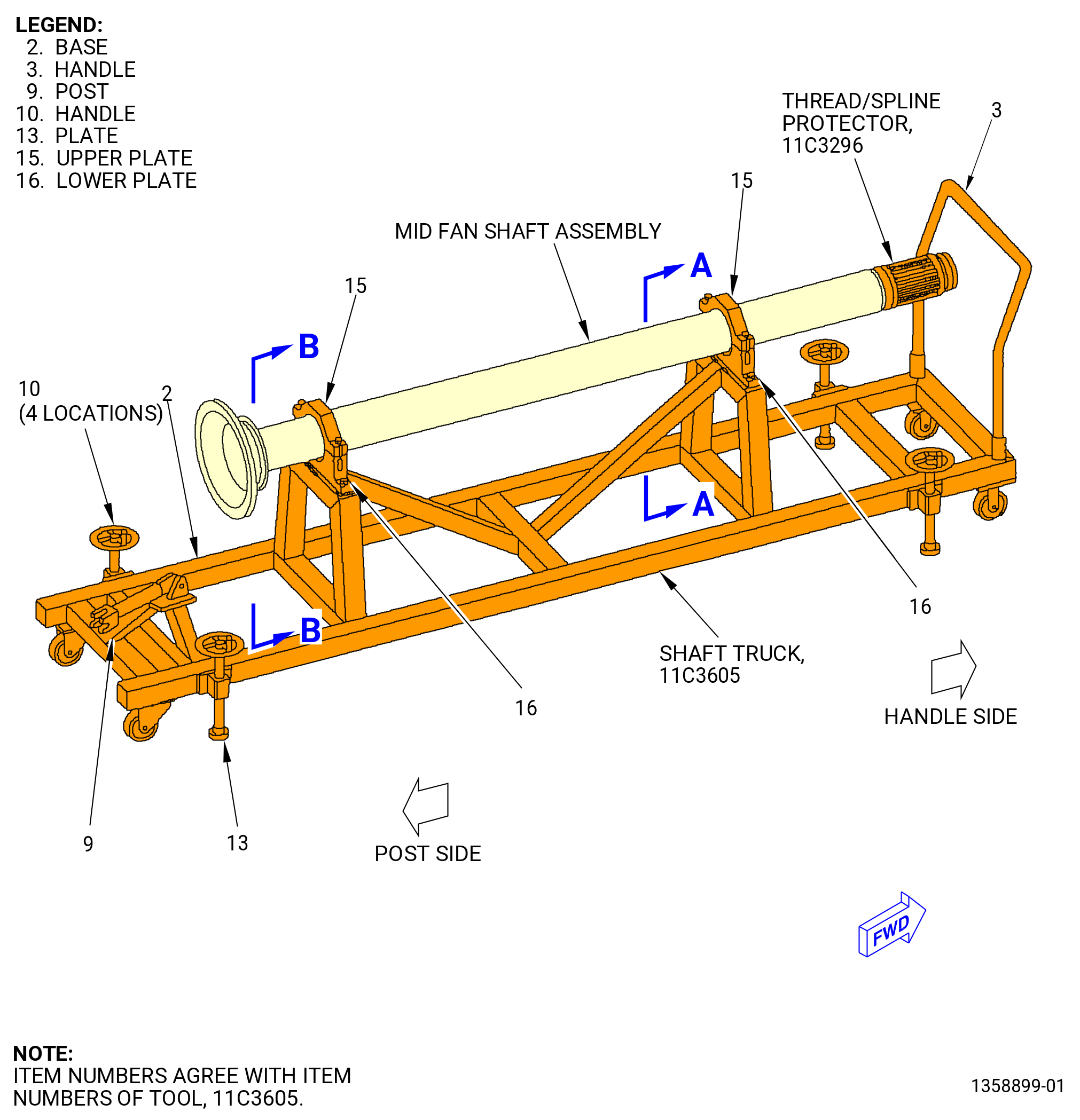
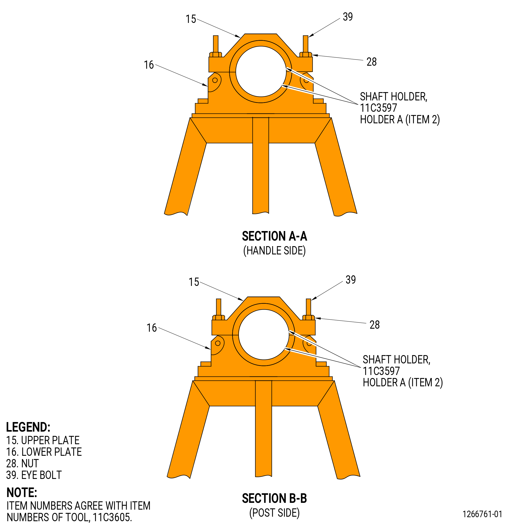
| B. | The mid fan shaft assembly is installed on the 11C3605 mid fan shaft truck with the 11C3597 shaft holder. Refer to Figure 502 and TASK 72-00-04-030-801 (72-00-04, Disassembly 001) . |
| C. | The balance bolts on the aft flange must not be removed. |
| 2 . | Tools, Equipment, and Materials. |
| NOTE: |
|
| A. | Tools and Equipment. |
| (1) | Special Tools. |
| (2) | Standard Tools and Equipment. None. |
| (3) | Locally Manufactured Tools. None. |
| B. | Consumable Materials. None. |
| C. | Referenced Procedures. |
|
| D. | Expendable Parts. None. |
|
|
| 3 . | Procedure. |
| Subtask 72-58-00-030-017 |
| A. | Remove the center vent tube (01-020) (SIN 810A1) from the mid fan shaft as follows: |
| CAUTION: |
|
| (1) | The plates (item 13) of the 11C3605 mid fan shaft truck must touch the floor to prevent movement of the shaft truck. Refer to Figure 502. |
| (2) | Remove the 11C3296 thread/spline protector from the mid fan shaft. |
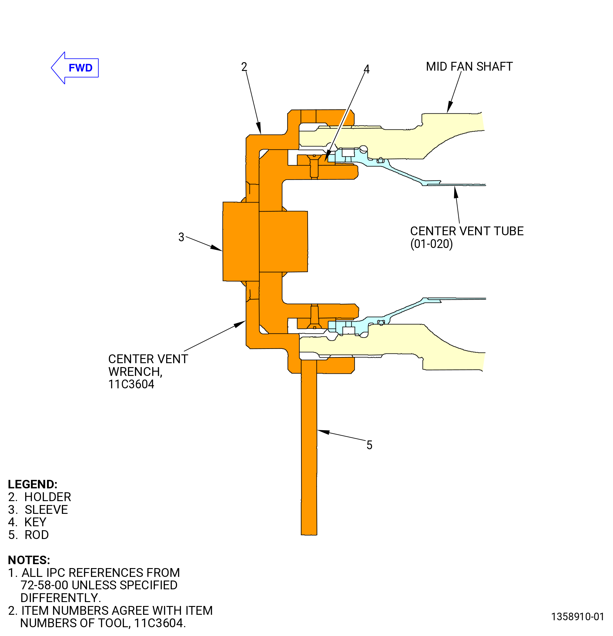
| (3) | Install the 11C3604 center vent wrench to the mid fan shaft assembly. Refer to Figure 503 and do as follows: |
| (a) | Install the sleeve (item 3) so the keys (item 4) engage with the slots of the center vent tube (01-020). |
| (b) | Install the holder (item 2) in the threads of the mid fan shaft. Manually tighten the holder with the rod (item 5). |
| (4) | Turn the sleeve (item 3) counterclockwise (CCW) with a breaker bar or equivalent to loosen the center vent tube (01-020). |
| (5) | Remove the 11C3604 center vent wrench. |
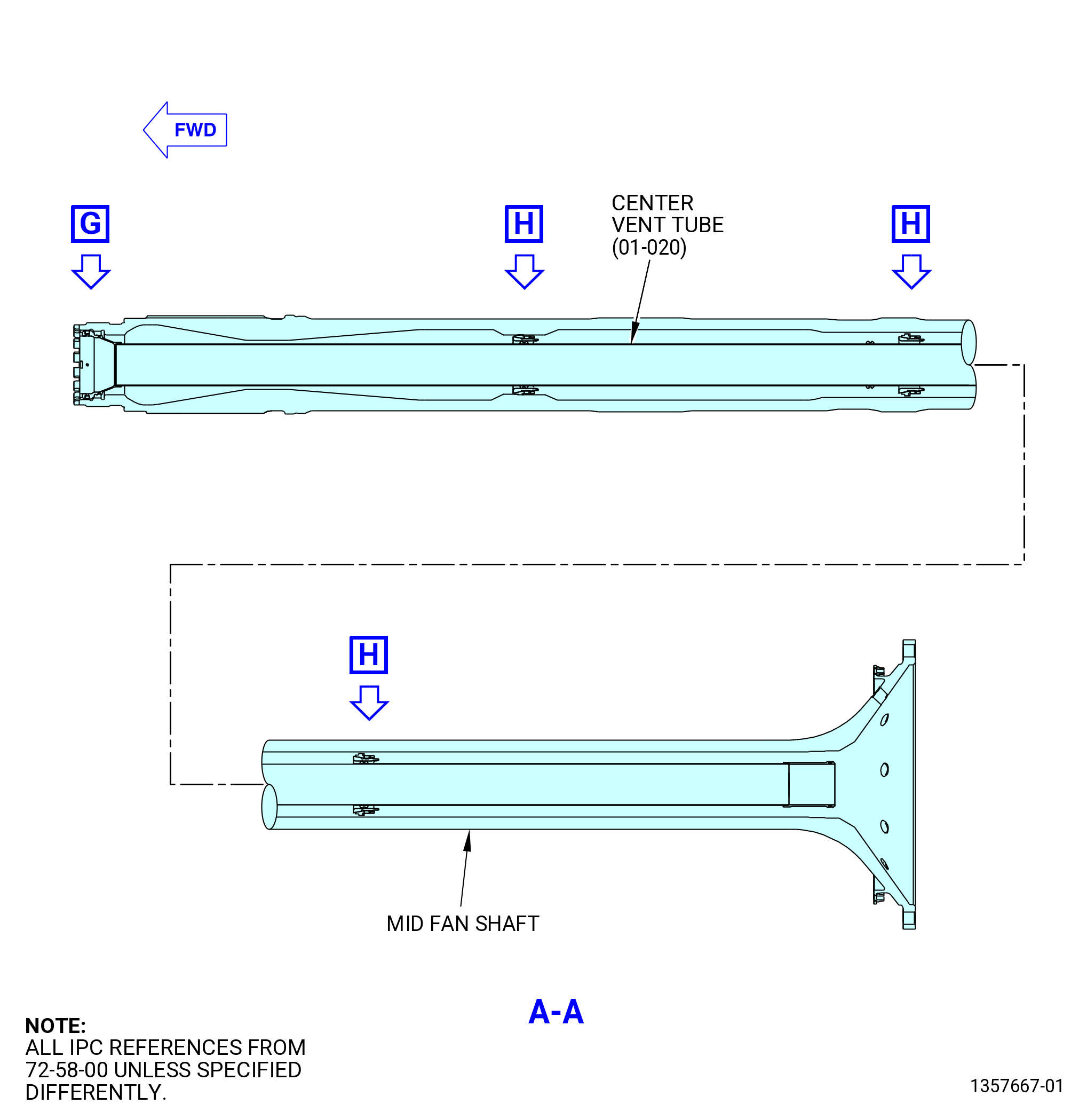
| (6) | Carefully pull the center vent tube (01-020) (SIN 810A1) forward out of the mid fan shaft. |
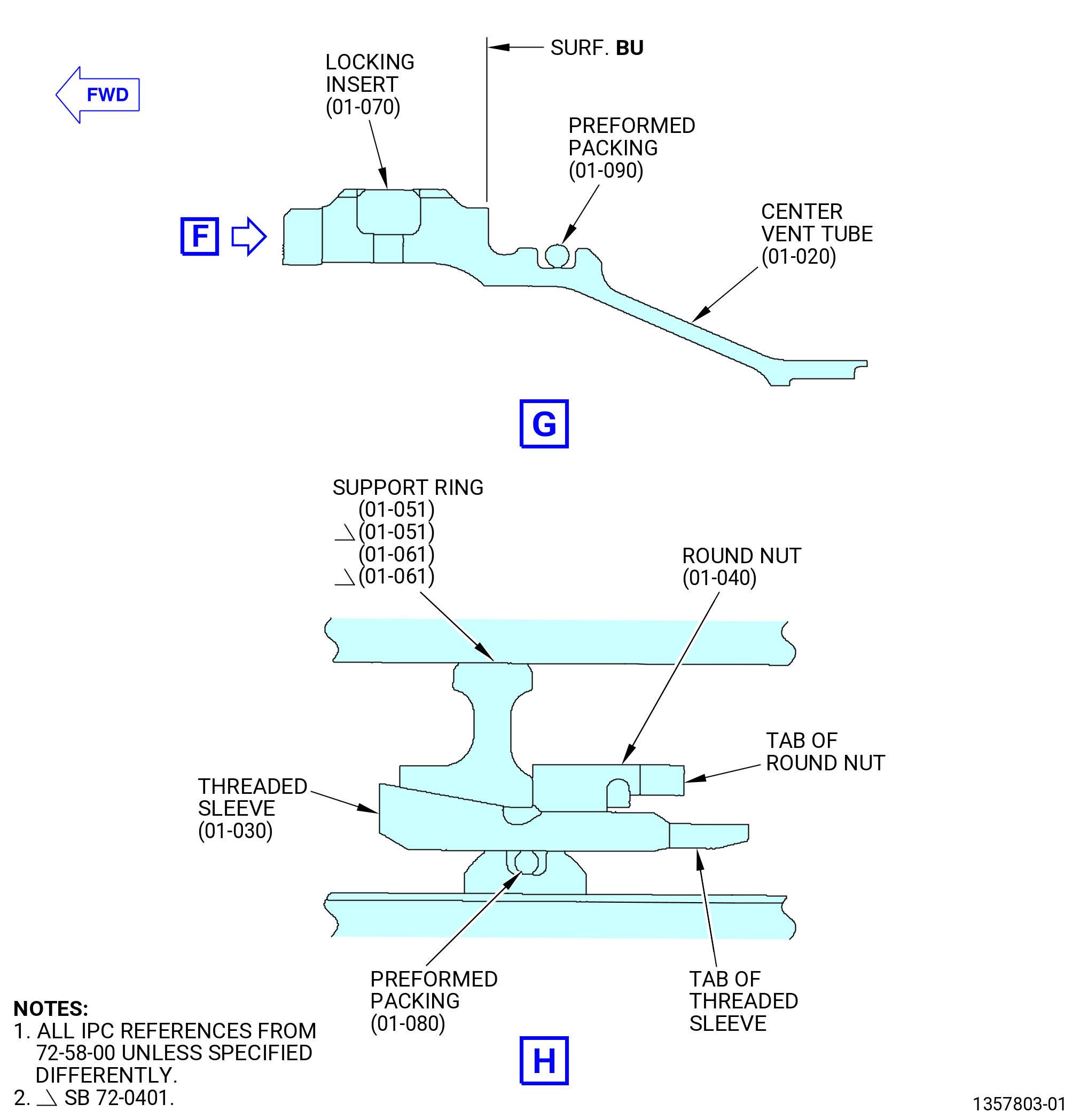
| (7) | Remove and discard the performed packing (01-090) (SIN 810N4), three preformed packings (01-080) (SIN 810N0), and the four locking inserts (01-070) (SIN 810K0) from the center vent tube (01-020). Refer to Figure 504. |
| Subtask 72-58-00-030-018 |
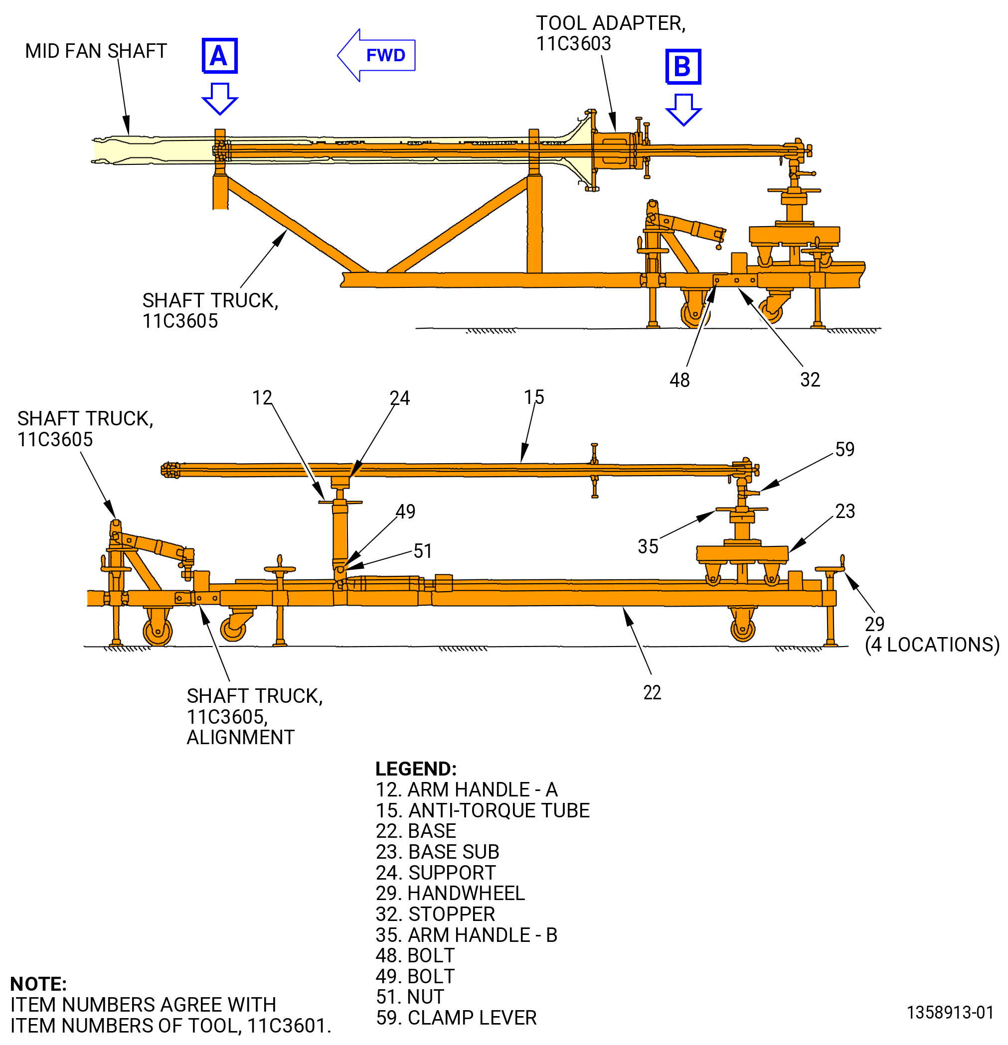
| B. | Attach the 11C3605 mid fan shaft truck to the 11C3601 install/remove tool as follows. Refer to Figure 505. |
| (1) | If the mid fan shaft is dirty with heavy coking that prevents the removal of the center vent tube, clean the mid fan shaft as follows: |
| Subtask 72-58-00-160-003 |
| (a) | Alternative Procedure Available. Clean the mid fan shaft assembly. Refer to TASK 70-21-06-110-004 (CLEANING METHOD NO. 6 - HEAVY-DUTY ALKALINE CLEANER (WITHOUT INHIBITED PHOSPHORIC ACID)), and as follows: |
| 1 | Discard and replace the round nut after you clean the mid fan shaft. |
| NOTE: |
|
| Subtask 72-58-00-160-004 |
| (a).A. | Alternative Procedure. Clean the mid fan shaft assembly. Contact GE for OEM approved cleaning procedure. |
| Subtask 72-58-00-030-029 |
| (2) | Lift the support (item 24) and hold it in the vertical position with the bolt (item 49) and nut (item 51). |
| (3) | Put the tube assembly of the 11C3601 install/remove tool on the support (item 24). |
| (3).A. | Tighten the clamp lever (item 59). |
| (4) | Align the 11C3605 mid fan shaft truck with the 11C3601 install/remove tool. |
| (5) | Adjust the height of the base (item 22) of the 11C3601 install/remove tool to the 11C3605 mid fan shaft truck with the hand wheels (item 29). Keep the base horizontal. |
| (6) | Level the 11C3605 mid fan shaft truck to the 11C3601 install/remove tool. |
| (7) | Attach the 11C3605 mid fan shaft truck to the 11C3601 install/remove tool with the stopper (item 32) and the bolts (item 48). |
| (8) | Hold the 11C3605 mid fan shaft truck to the floor with the handles (item 10) so the base (item 2) of the 11C3605 mid fan shaft truck is horizontal. Refer to Figure 502. |
| (9) | Deleted. |
| (10) | Deleted. |
| (11) | Make sure that the axis of the tube assembly aligns with the axis of the mid fan shaft on the 11C3605 mid fan shaft truck. If necessary, adjust the height of the tube assembly with the arm handle-A (item 12) and arm handle-B (item 35). Refer to Figure 505. |
| Subtask 72-58-00-030-019 |
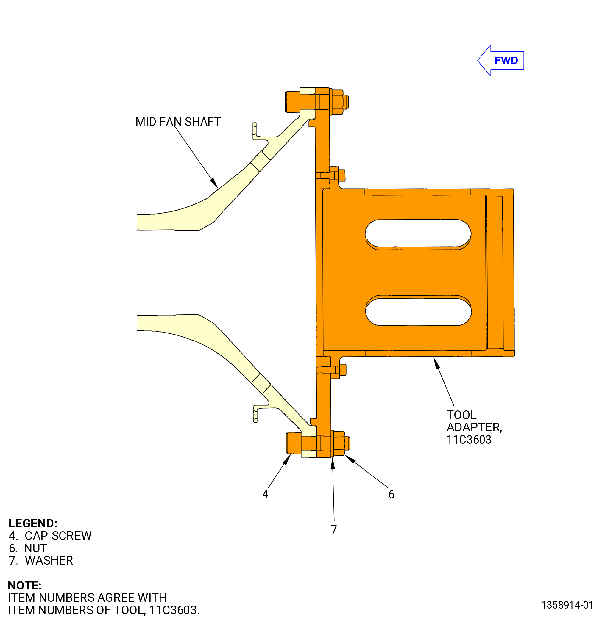
| C. | Attach the 11C3603 tool adapter to the aft end of the mid fan shaft with the cap screws (item 4), washers (item 7), and nuts (item 6). Refer to Figure 506. |
| Subtask 72-58-00-030-020 |
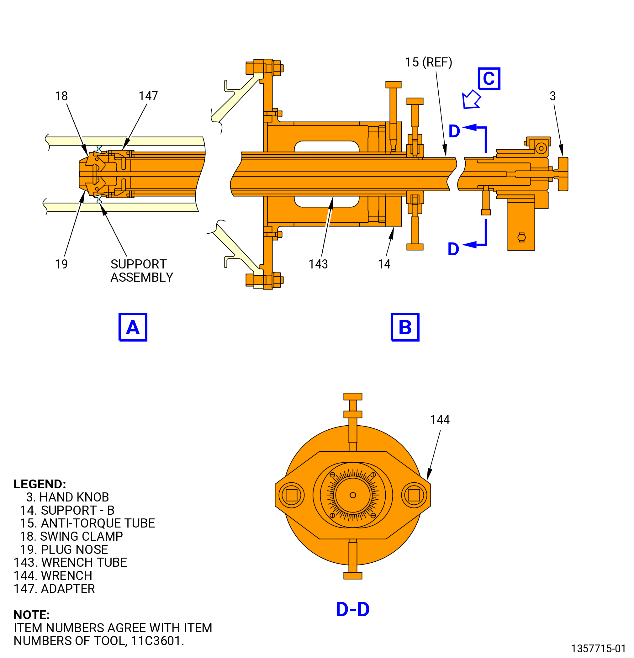
| D. | Install the 11C3601 install/remove tool to the 11C3603 tool adapter as follows. Refer to Figure 505. |
| (1) | Deleted. |
| (2) | Deleted. |
| (3) | Move the support-B (item 14) forward and install it to the 11C3603 tool adapter. |
| (4) | Remove the bolt (item 49) and the nut (item 51) and put the support (item 24) down in the forward direction. |
| Subtask 72-58-00-030-021 |
| E. | Remove the aft support ring assembly (01-051) (SIN 810A6) from the mid fan shaft. Refer to Figure 505 and do as follows: |
| NOTE: |
|
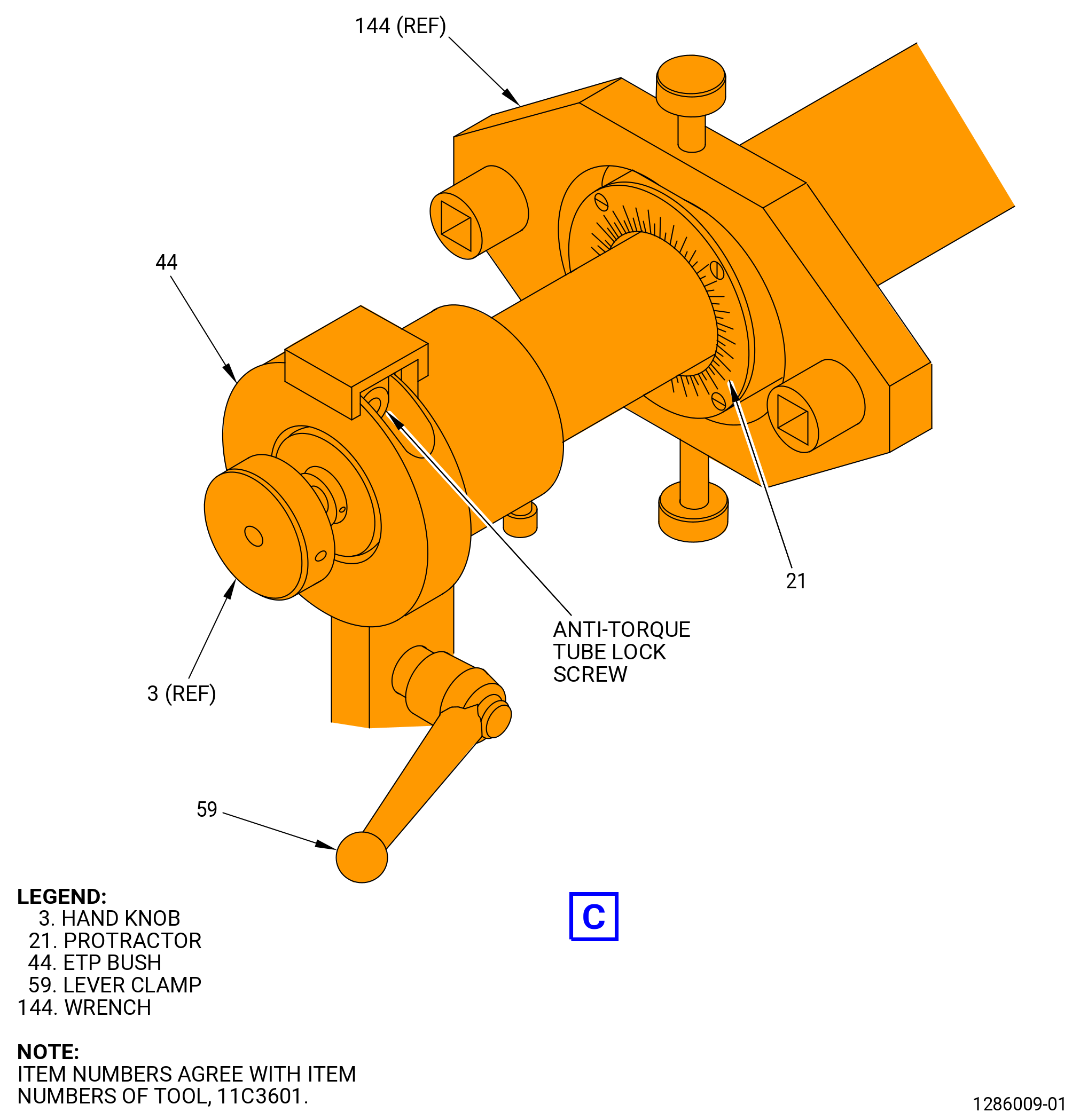
| (1) | Loosen the round nut (01-040) of the aft support ring assembly with the 11C3601 install/remove tool as follows: |
| (a) | Turn the hand knob (item 3) CCW to retract the swing clamps (item 18). |
| (b) | Carefully insert the anti-torque tube (item 15) into the mid fan shaft from the aft end. |
| (c) | Align the slots in the plug nose (item 19) with the tabs of the threaded sleeve (01-030). |
| NOTE: |
|
| (d) | Carefully push the anti-torque tube (item 15) until the tabs of the threaded sleeve (01-030) fully engage with the slots in the plug nose (item 19). |
| (e) | Turn the hand knob (item 3) clockwise to open the swing clamps (item 18) so the threaded sleeve (01-030) is held on the plug nose (item 19). |
| (f) | Align the tabs of the round nut (01-040) (SIN 810A4) with the slots in the adapter (item 147). |
| NOTE: |
|
| (g) | Carefully push the wrench tube (item 143) until the tabs of the round nut (01-040) (SIN 810A4) fully engage with the slots in the adapter (item 147). |
| (h) | Tighten the anti-torque tube lock screw on the ETP bush (item 44) to hold the anti-torque tube (item 15). |
| (i) | Install a breaker bar or equivalent in the wrench square of the wrench (item 144). |
| (j) | Turn the wrench (item 144) CCW to loosen the round nut (01-040) (SIN 810A4). |
| (k) | Loosen the anti-torque tube lock screw on the ETP bush (item 44). |
| (l) | Turn the anti-torque tube (item 15) manually to make sure that the aft support ring assembly (01-051) (SIN 810A6) is free in the mid fan shaft. |
| 1 | If necessary, do the above steps again until you can turn the aft support ring assembly (01-051) (SIN 810A6) freely in the mid fan shaft. |
| (2) | Carefully move the tube assembly aft until the aft support ring assembly (01-051) (SIN 810A6) comes out of the mid fan shaft. |
| (3) | Remove the aft support ring assembly (01-051) from the 11C3601 install/remove tool as follows: |
| (a) | Turn the hand knob (item 3) CCW to retract the swing clamps (item 18). |
| (b) | Remove the aft support ring assembly (01-051) from the plug nose (item 19). |
| Subtask 72-58-00-030-022 |
| F. | Remove the mid support assembly (01-051) (SIN 810A6) from the mid fan shaft. Refer to aft support ring assembly removal procedure in Subtask 72-58-00-030-021 (paragraph 3.E.). |
| NOTE: |
|
| Subtask 72-58-00-030-023 |
| G. | Remove the forward support assembly (01-061) (SIN 810A7) from the mid fan shaft. Refer to aft support assembly removal procedure in Subtask 72-58-00-030-021 (paragraph 3.E.). |
| NOTE: |
|
| Subtask 72-58-00-030-032 |
| H. | Lift the support (item 24) of the 11C3601 install/remove tool. |
| Subtask 72-58-00-030-033 |
| I. | Remove the support-B (item 14) of the 11C3601 install/remove tool from the 11C3603 tool adapter. |
| Subtask 72-58-00-030-024 |
| J. | Remove the 11C3603 tool adapter from the mid fan shaft. |
| Subtask 72-58-00-030-025 |
| K. | Disassemble each of the support assemblies with the 11C3598 torque fixture as follows. Refer to Figure 509. |
| (1) | Attach the base (item 5) to a worktable. |
| (2) | Remove the sleeve (item 3), the socket (item 2), the set block (item 4), and the cap screw (item 6) from the base (item 5). |
| (3) | Put the support assembly on the base (item 5) with the support ring (01-061) down. |
| (4) | Align the slots of the set block (item 4) with the two tabs of the threaded sleeve (01-030). Install the set block on the base (item 5) with the cap screw (item 6). |
| (5) | Align the slots of the socket (item 2) with the tabs of the round nut (01-040). Install the socket on the round nut (01-040). |
| (6) | Install the sleeve (item 3) over the socket (item 2). |
| (7) | Loosen and remove the round nut (01-040). |
| (8) | Remove the support ring (01-061) and threaded sleeve (01-030) from the 11C3598 torque fixture. |
| Subtask 72-58-00-030-026 |
| L. | Do the preservation procedure for all of the unpainted surfaces of the mid fan shaft. Refer to TASK 72-58-00-550-801 (72-58-00, Storage 001). |
| Subtask 72-58-00-030-027 |
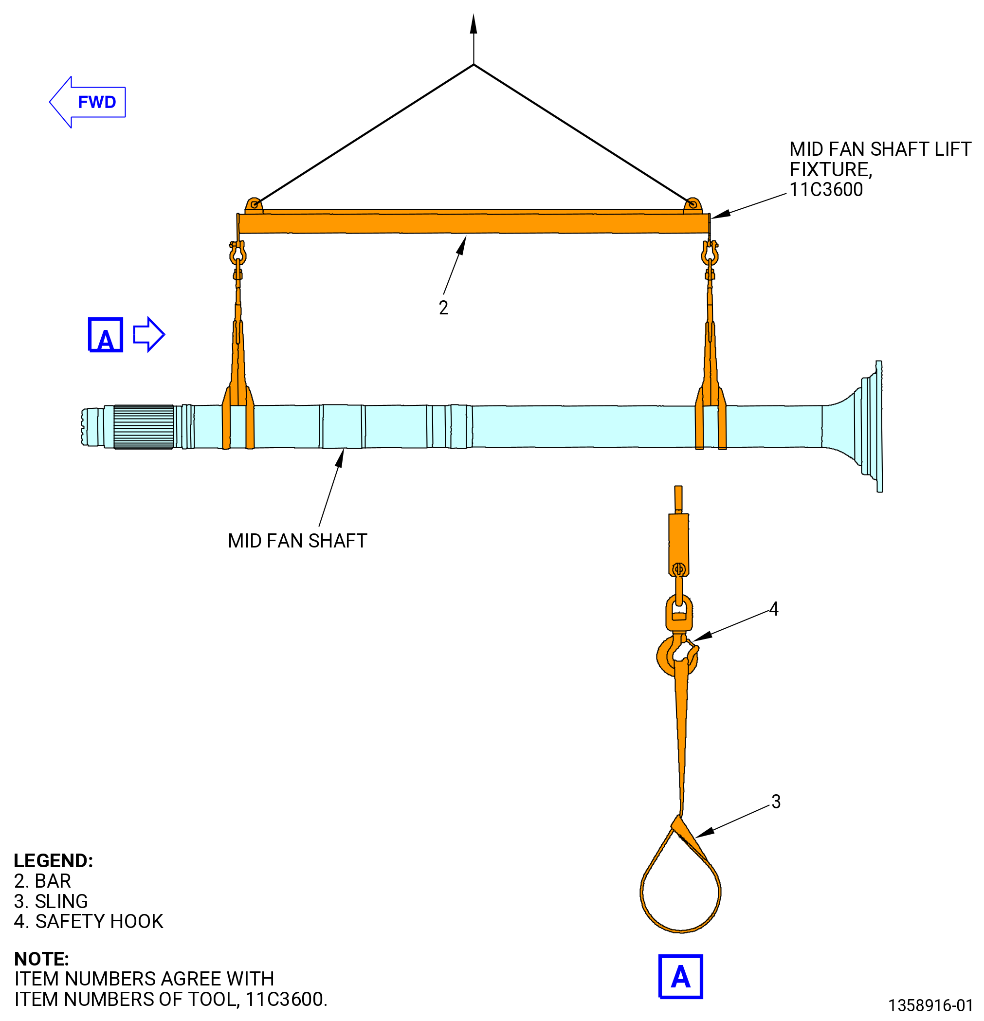
| M. | If necessary, remove the mid fan shaft from the 11C3605 mid fan shaft truck with the 11C3600 mid fan shaft lift fixture as follows: |
| (1) | Attach the 11C3600 mid fan shaft lift fixture to the mid fan shaft. Refer to Figure 510 and do as follows: |
| NOTE: |
|
| (a) | Remove the slings (item 3) from the safety hooks (item 4). |
| (b) | Attach the slings (item 3) at two locations to the mid fan shaft. Double the sling straps around the shaft. |
| (c) | Attach an overhead hoist to the spreader bar (bar) (item 2) at two locations. |
| WARNING: |
|
| (d) | Lift the bar (item 2) with an overhead hoist and attach the slings (item 3) to the safety hooks (item 4). |
| (e) | Remove unwanted slack from the slings (item 3) with the overhead hoist. |
| (2) | Remove the mid fan shaft from the 11C3605 mid fan shaft truck. Refer to Figure 502. |
| (a) | Loosen the nuts (item 28) at two locations and remove the upper plates (item 15) from the mid fan shaft and the lower plates (item 16). |
| WARNING: |
|
| CAUTION: |
|
| (b) | Carefully lift the mid fan shaft from the 11C3605 mid fan shaft truck. |
| (3) | Safely store the mid fan shaft. |