| GENX-1B ENGINE MANUAL | Dated: 12/29/2022 | |
| EM 72-00-00 , DISASSEMBLY 001 | ||
| ENGINE ASSEMBLY - DISASSEMBLY 001 | ||
| GENX-1B ENGINE MANUAL | Dated: 12/29/2022 | |
| EM 72-00-00 , DISASSEMBLY 001 | ||
| ENGINE ASSEMBLY - DISASSEMBLY 001 | ||
| * * * FOR ALL |
| TASK 72-00-00-030-801 |
| 1 . | General. |
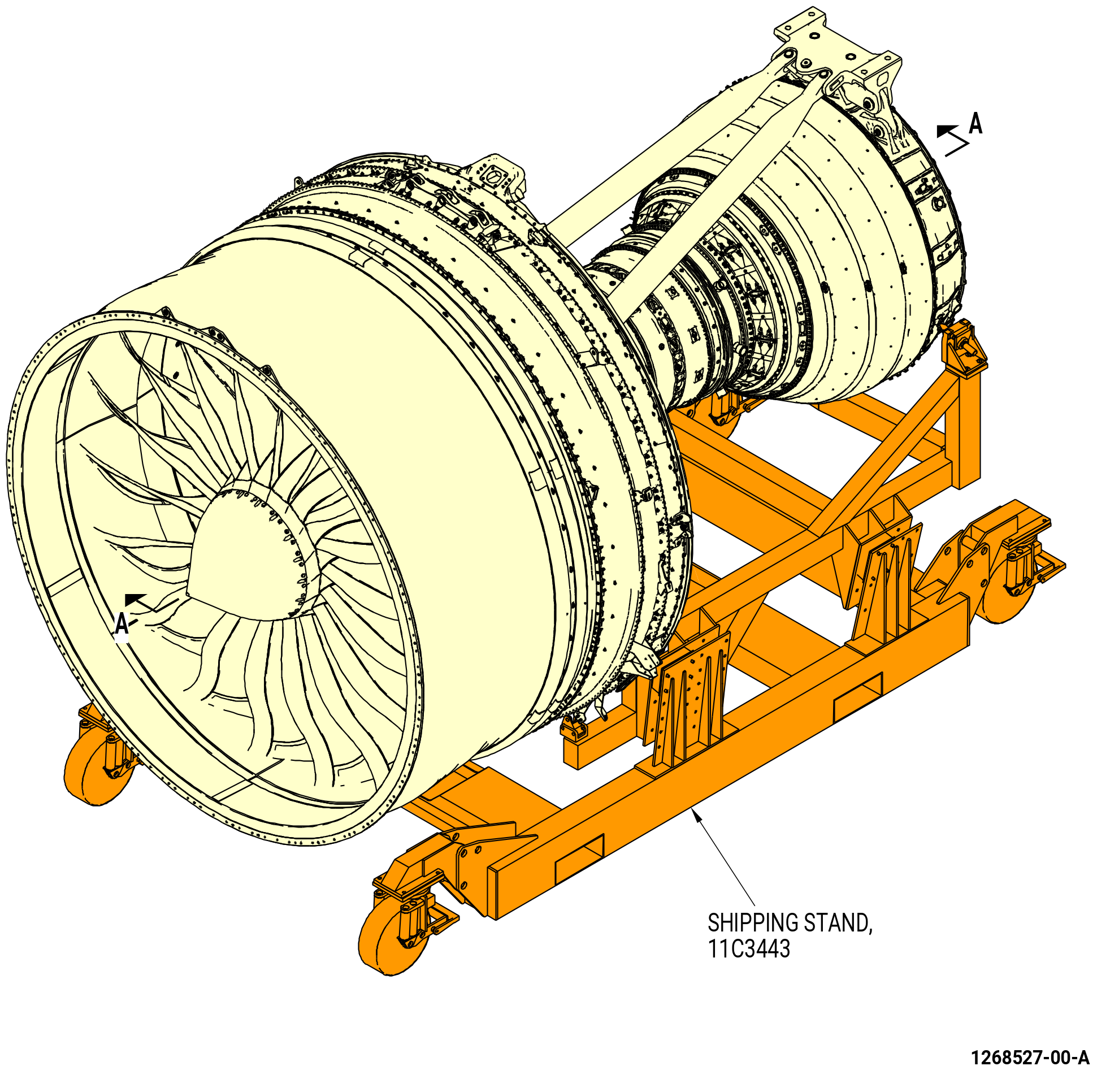
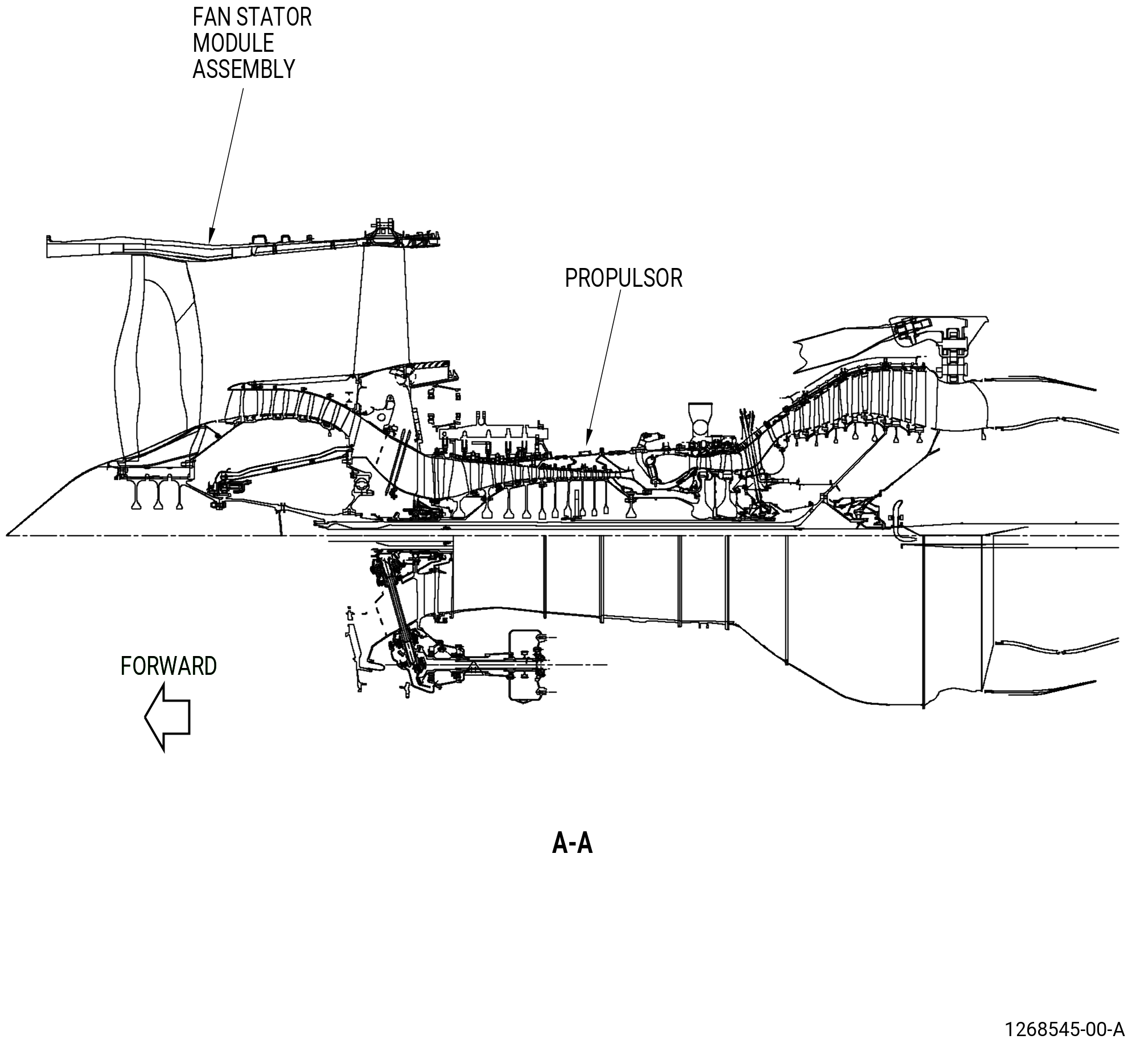
| A. | This procedure gives instructions to disassemble the GEnx™ series engine assembly. This procedure includes instructions to disassemble powerplant items, electrical harnesses, electronic engine control (EEC) (65H00), engine monitoring unit (EMU) (65Z00), lower bifurcation assembly, fan stator module assembly, and propulsor. Refer to Figure 501. |
| B. | This procedure starts with the propulsor module assembly (propulsor) in the horizontal position. The propulsor can be installed in the 11C3443 shipping stand, or 11C3044 engine module adapter assembly, or attached to the customer overhead rail system, or supported by the 11C3281 pedestals, at the equivalent disassembly status of TASK 72-00-02-030-801 (72-00-02, DISASSEMBLY 001) . |
| • |
|
| • |
|
| • |
|
| • |
|
| C. | Make sure the engine assembly has the correct support at all times to prevent injury to personnel or damage to engine parts. |
| D. | Tag parts for special inspection if the engine assembly was operated in unusual conditions. |
| E. | Make sure that personnel read this procedure and know the step-by-step instructions and special tool use before they disassemble the engine assembly. |
| 2 . | Tools, Equipment, and Materials. |
| NOTE: |
|
| A. | Tools and Equipment. |
| (1) | Special Tools. |
| (2) | Standard Tools and Equipment. |
|
| (3) | Locally Manufactured Tools. None. |
| B. | Consumable Materials. None. |
| C. | Referenced Procedures. |
|
| D. | Expendable Parts. None. |
| 3 . | Procedure. |
| Subtask 72-00-00-030-223 |
| A. | Remove the engine build unit (EBU) PTT (738L103) as follows. Refer to Figure 502. |
| WARNING: |
|
| CAUTION: |
|
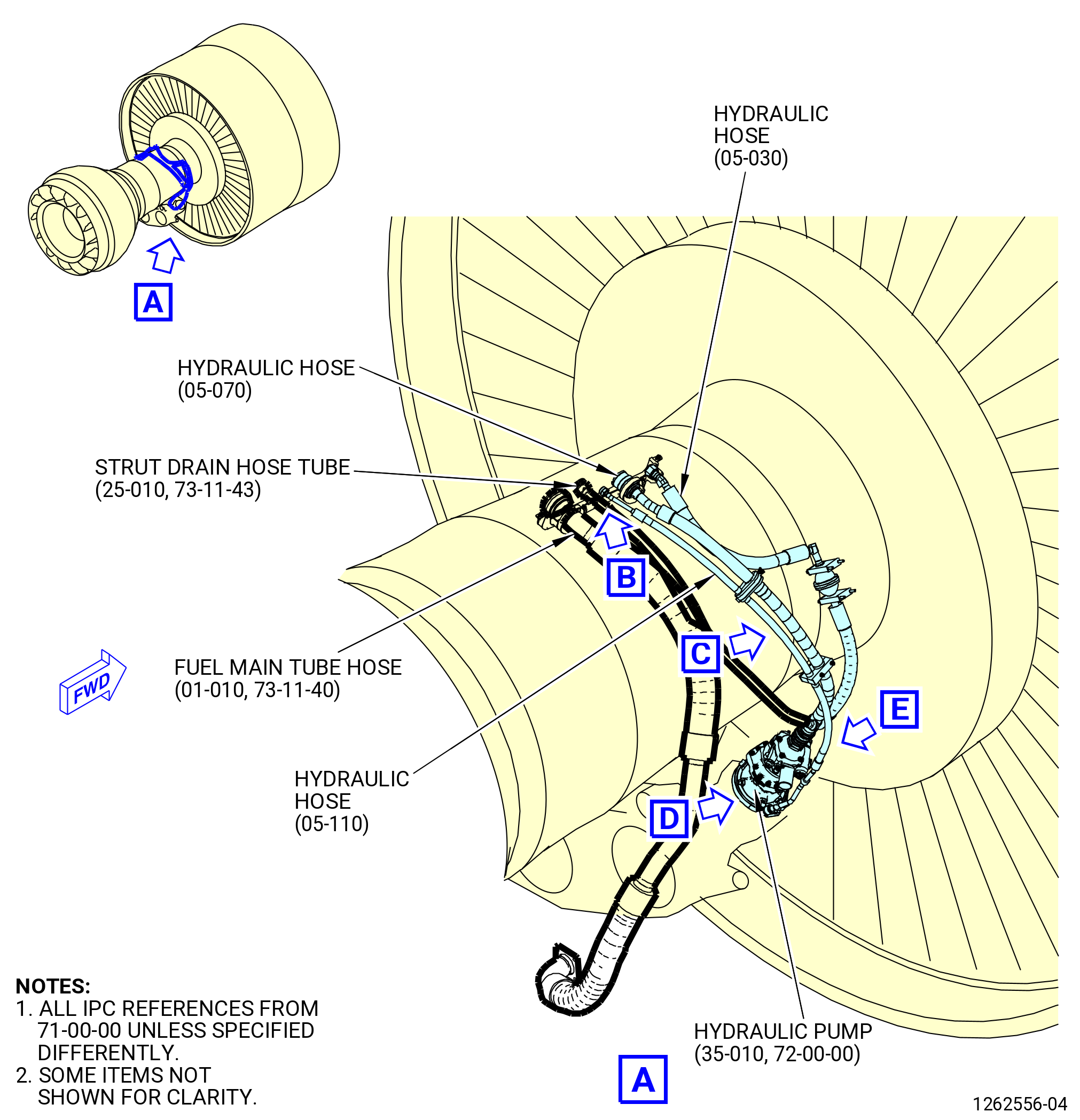
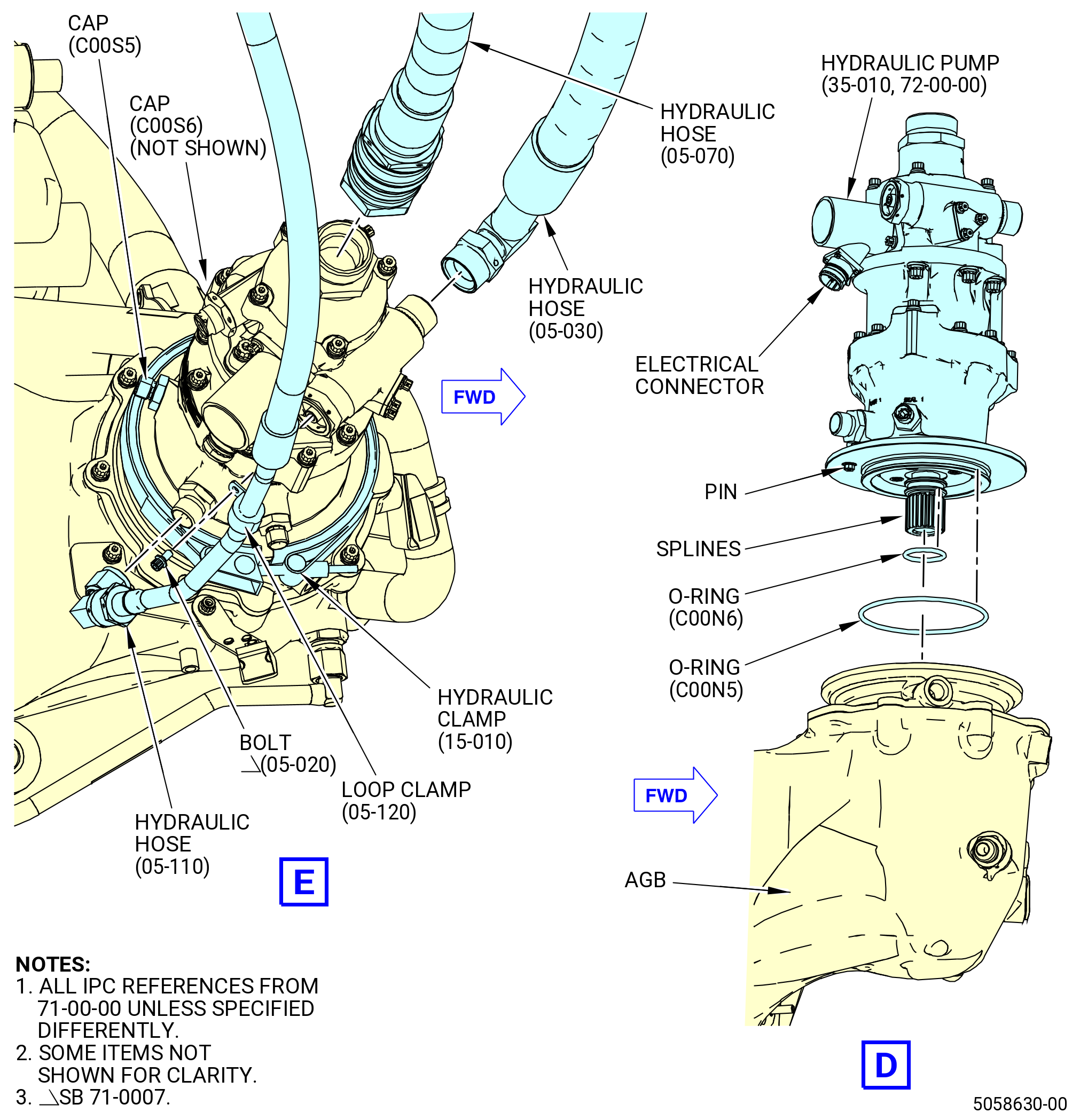
| (1) | Remove the hydraulic hose assemblies (hydraulic hose) (05-070 , 71-00-00) (SIN 53000), (05-030 , 71-00-00) (SIN 53100), and (05-110 , 71-00-00) (SIN 53200) from the hydraulic pump. Refer to Figure 502 and do as follows: |
| (a) | Loosen the coupling nut and remove the hydraulic hose (05-070 , 71-00-00) (SIN 53000) from the top of the hydraulic pump (35-010) (SIN C00A6). |
| (b) | Loosen the coupling nut and remove the hydraulic hose (53100) from the forward side of the hydraulic pump. |
| (c) | Loosen and remove the bolt and loop clamp (53280) from the hydraulic hose (53200) on the aft side of the hydraulic pump. |
| (d) | Loosen the coupling nut and remove the hose from the hydraulic pump. |
| (2) | Remove the hydraulic hose assemblies (53000, 53100, 53200) as follows. Refer to Figure 502. |
| (a) | Remove the bolts and the P-clamp (53080) that attach the two hydraulic hoses (53000, 53200) together. |
| Subtask 72-00-00-030-296 |
| * * * PRE SB 72-0057( One Clamp Hose Support ) |
| (b) | Remove the bolt and clamp (53081) that attach the two hydraulic hoses (53000, 53200) together. |
| * * * END PRE SB 72-0057 |
| Subtask 72-00-00-030-297 |
| * * * SB 72-0057( Two Clamp Hose Support ) |
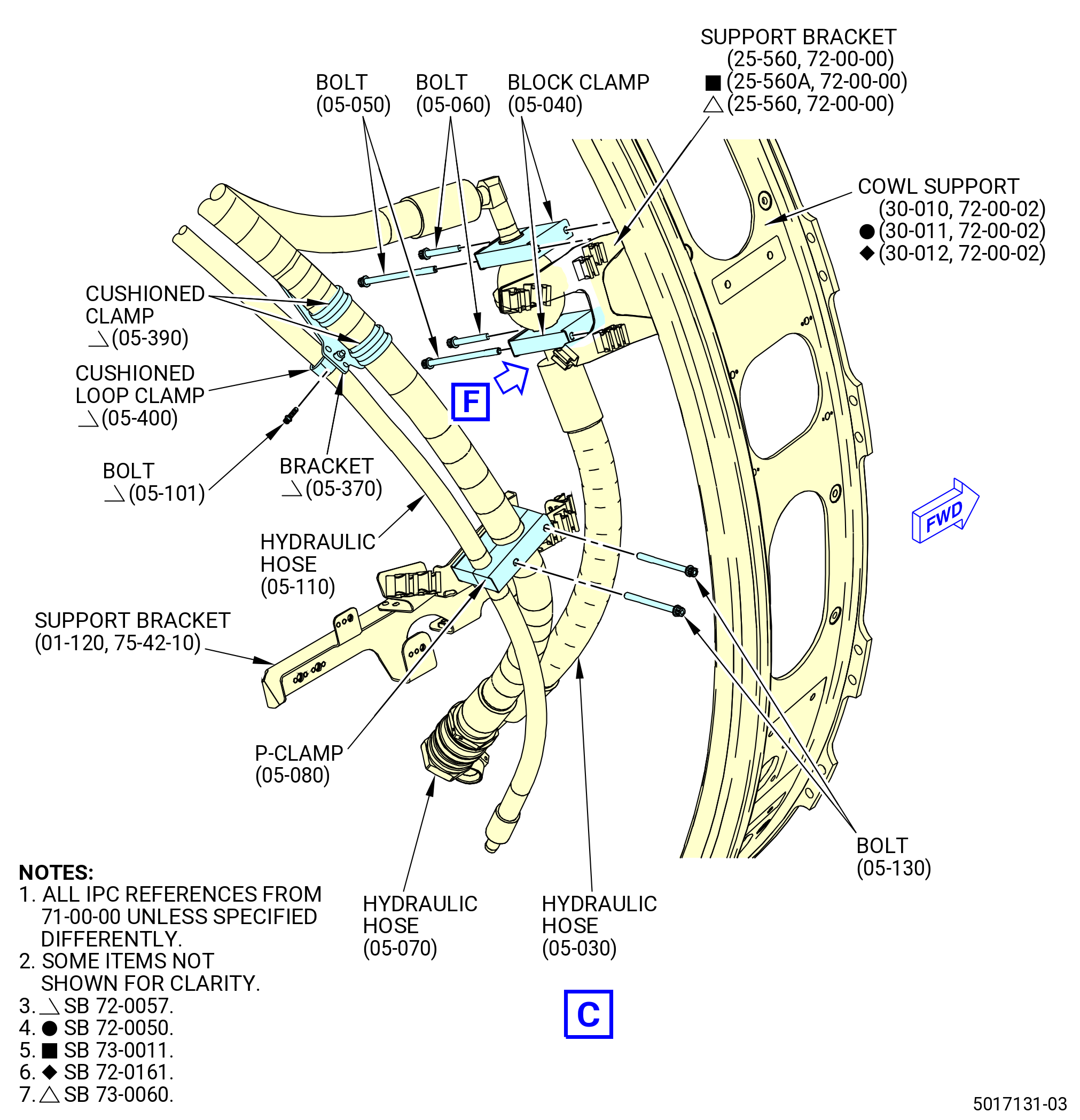
| (b).A. | Remove the bolts (05-101 , 71-00-00), bracket (05-370 , 71-00-00), cushioned loop clamp (05-400 , 71-00-00) and cushioned clamps (05-390 , 71-00-00) that attach the two hydraulic hoses (53000, 53200) together. |
| * * * END SB 72-0057 |
| Subtask 72-00-00-030-312 |
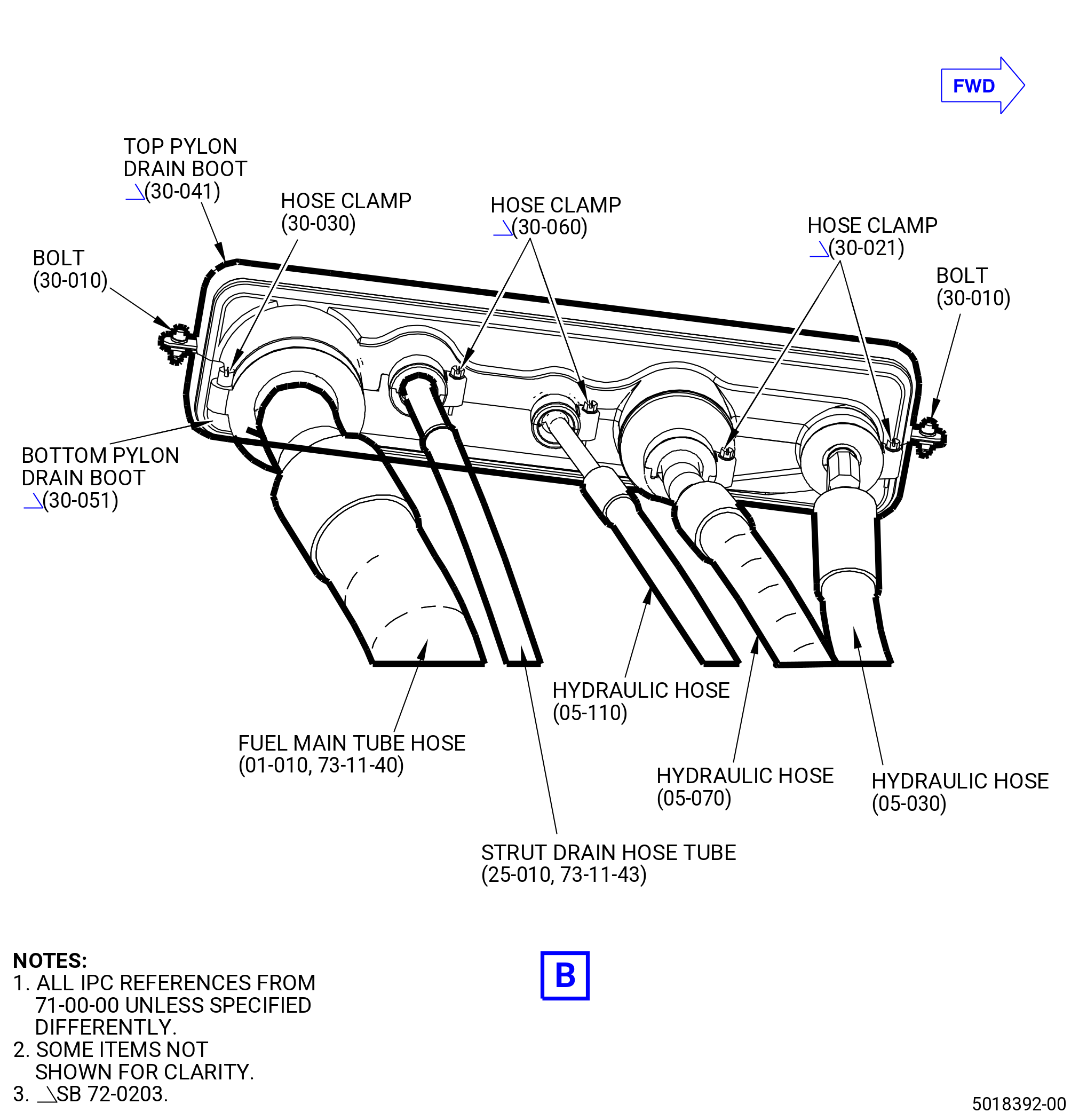
| * * * PRE SB 72-0203( Installation of the Drain Boots without Additional Clamps ) |
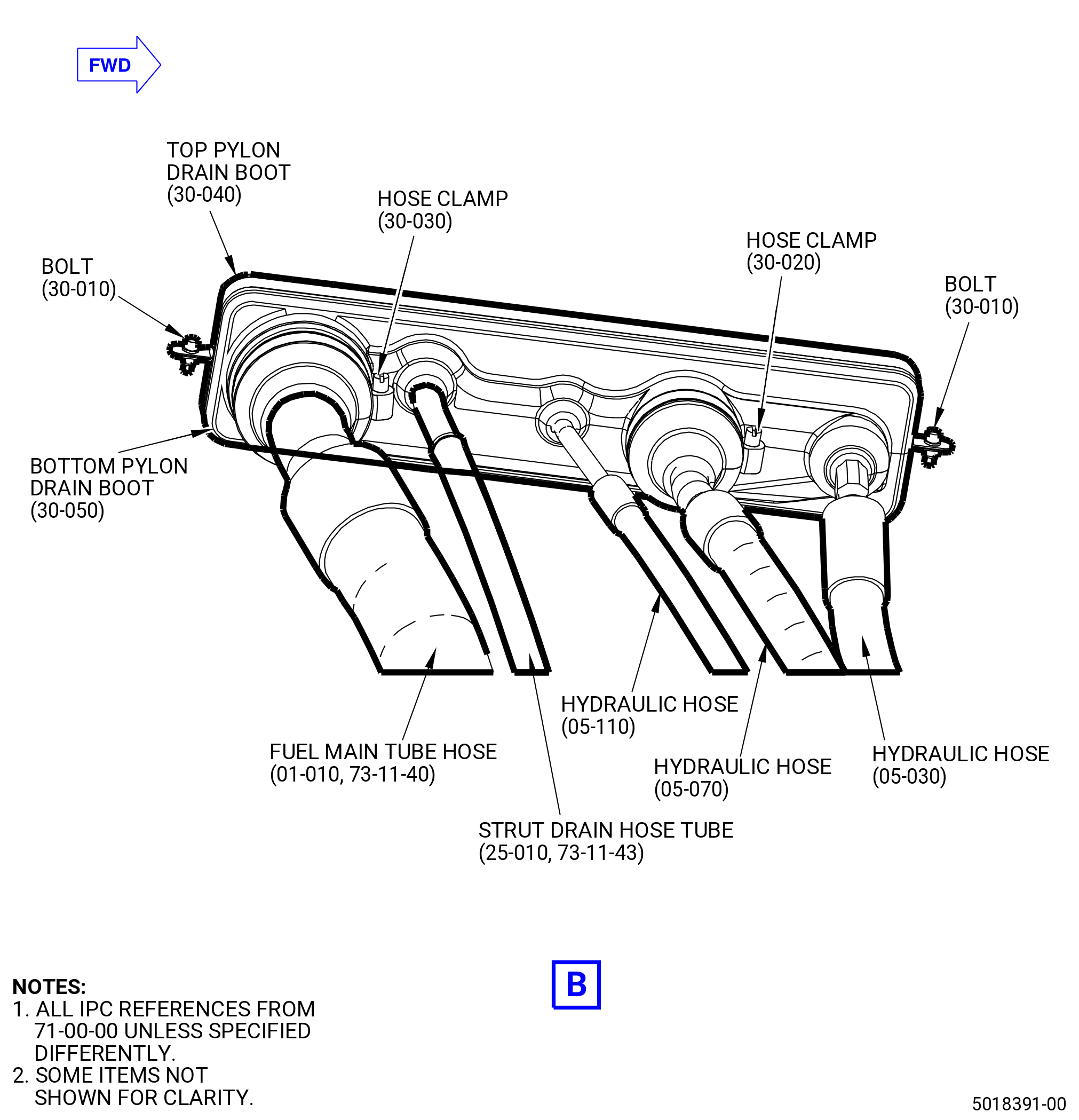
| (c) | Remove the hose clamps (30-020 , 71-00-00) (SIN 59083) and (30-030 , 71-00-00) (SIN 59085) that attach the top and bottom pylon drain boots (30-040 , 71-00-00) (SIN 59090) and (30-050 , 71-00-00) (SIN 59091). |
| * * * END PRE SB 72-0203 |
| Subtask 72-00-00-030-313 |
| * * * SB 72-0203( Installation of the New Drain Boots with Additional Clamps ) |
| (c).A. | Remove the hose clamps (30-021 , 71-00-00) (SIN 59083), (30-030 , 71-00-00) (SIN 59085), and (30-060 , 71-00-00) (SIN 59086) that attach the top and bottom pylon drain boots (30-041 , 71-00-00) (SIN 59090) and (30-051 , 71-00-00) (SIN 59091). |
| * * * END SB 72-0203 |
| Subtask 72-00-00-030-298 |
| (d) | Loosen and remove the two double hexagonal head machine bolts (bolts) (30-010 , 71-00-00) (SIN 59022) that attach the top and bottom pylon drain boots (30-040 , 71-00-00) (SIN 59090) or (30-041 , 71-00-00) (SIN 59090) and (30-050 , 71-00-00) (SIN 59091) or (30-051 , 71-00-00) (SIN 59091). |
| (e) | Remove the hydraulic hoses (01-010 , 73-11-40) (SIN 34000), (05-070 , 71-00-00) (SIN 53000), (05-110 , 71-00-00) (SIN 53200), and (25-010 , 73-11-43) (SIN 59000) from the bottom pylon drain boot. |
| (f) | Put protective covers at each end of the hydraulic hoses. |
| (g) | Loosen and remove the four bolts and two block clamps (05-040 , 71-00-00) (SIN 53180) that attach the hydraulic hose (05-030 , 71-00-00) (SIN 53100) to the support bracket (25-560) (SIN 6881U) or (25-560A) (SIN 6881U) on the inboard side of the cowl support (30-010 , 72-00-02) (SIN 95001) or (30-011 , 72-00-02) (SIN 95001) or (30-012 , 72-00-02) (SIN 95001). |
| (h) | Remove the hydraulic hose (05-030 , 71-00-00) (SIN 53100) from the bottom pylon drain boot. |
| (i) | Put a protective cover at the end of the hydraulic hose (53100). |
| (9) | Remove the hydraulic pump (35-010) (SIN C00A6) from the AGB. Refer to Figure 502 and do as follows: |
| (a) | Use soft-jaw pliers to remove the electrical cable from the hydraulic pump. |
| (b) | Loosen and remove the hydraulic clamp (C00V2) that attaches the hydraulic pump to the pad on the AGB. |
| WARNING: |
|
| CAUTION: |
|
| (c) | Carefully lift the hydraulic pump straight up and away from the AGB. Make sure that you do not damage the splines of the hydraulic pump with too much side-to-side motion during removal. |
| (d) | Remove and discard the two o-rings (C00N5, C00N6) from the hydraulic pump. |
| (e) | Put protective covers on the connections of the hydraulic pump and splines shaft. |
|
|
|
|
|
|
| Subtask 72-00-00-030-224 |
| * * * FOR 1B/P/G03.1B/P/G04.1B/P1/G01 |
| * * * PRE SB 72-0066( Fire Extinguishing System with Fire Suppression Tubes ) |
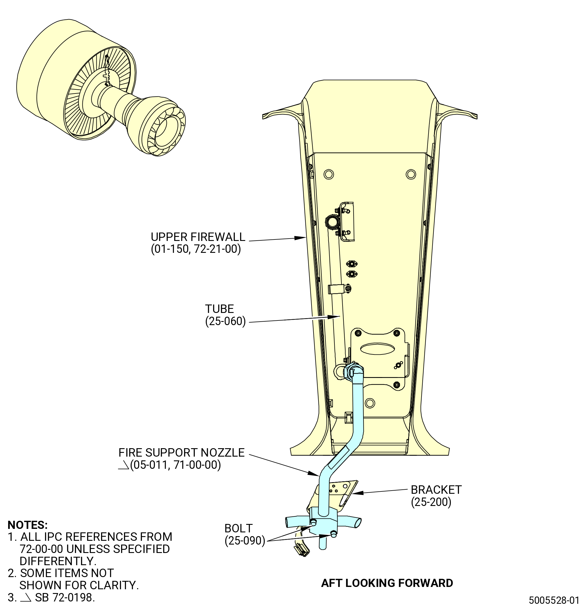
| B. | Remove the fire support nozzle (05-010 , 71-00-00) (SIN 9900A). Refer to Figure 503 and do as follows: |
| (1) | Disconnect the tube (25-060) (SIN 99302) from the fire support nozzle (05-010 , 71-00-00) (SIN 9900A). |
| (2) | Disconnect the fire support nozzle from the tube (60-010 , 72-00-02) (SIN 99301), remove the bolts (25-090) (SIN 99329) from the bracket (25-200) (SIN 9931A), and remove the fire support nozzle. |
| * * * END PRE SB 72-0066 |
| Subtask 72-00-00-030-308 |
| * * * FOR 1B/P/G03.1B/P/G04.1B/P1/G01 |
| * * * PRE SB 72-0198( Fire Extinguishing System - PIP/PIP1 Configuration ) |
| * * * SB 72-0066( Fire Extinguishing System without Fire Suppression Tubes ) |
| B.A. | Remove the fire support nozzle (05-010 , 71-00-00) (SIN 9900A). Refer to Figure 503 and do as follows: |
| (1) | Disconnect the tube (25-060) (SIN 99302) from the fire support nozzle (05-010 , 71-00-00) (SIN 9900A). |
| (2) | If necessary, remove the tube cap (05-410 , 71-00-00) (SIN 99064) from the fire support nozzle. |
| (3) | Remove the bolts (25-090) (SIN 99329) from the bracket (25-200) (SIN 9931A). Remove the fire support nozzle. |
| * * * END PRE SB 72-0198 |
| * * * END SB 72-0066 |
| Subtask 72-00-00-030-309 |
| * * * FOR ALL PIP 2 |
| * * * SB 72-0198( Fire Extinguishing System - PIP 2 Configuration ) |
| B.B. | Remove the fire support nozzle (05-011 , 71-00-00) (SIN 9900A). Refer to Figure 503 and do as follows: |
| (1) | Disconnect the tube (25-060) (SIN 99302) from the fire support nozzle. |
| (2) | Remove the bolts (25-090) (SIN 99329) from the bracket (25-200) (SIN 9931A). Remove the fire support nozzle. |
| * * * END SB 72-0198 |
| Subtask 72-00-00-030-249 |
| * * * FOR ALL |
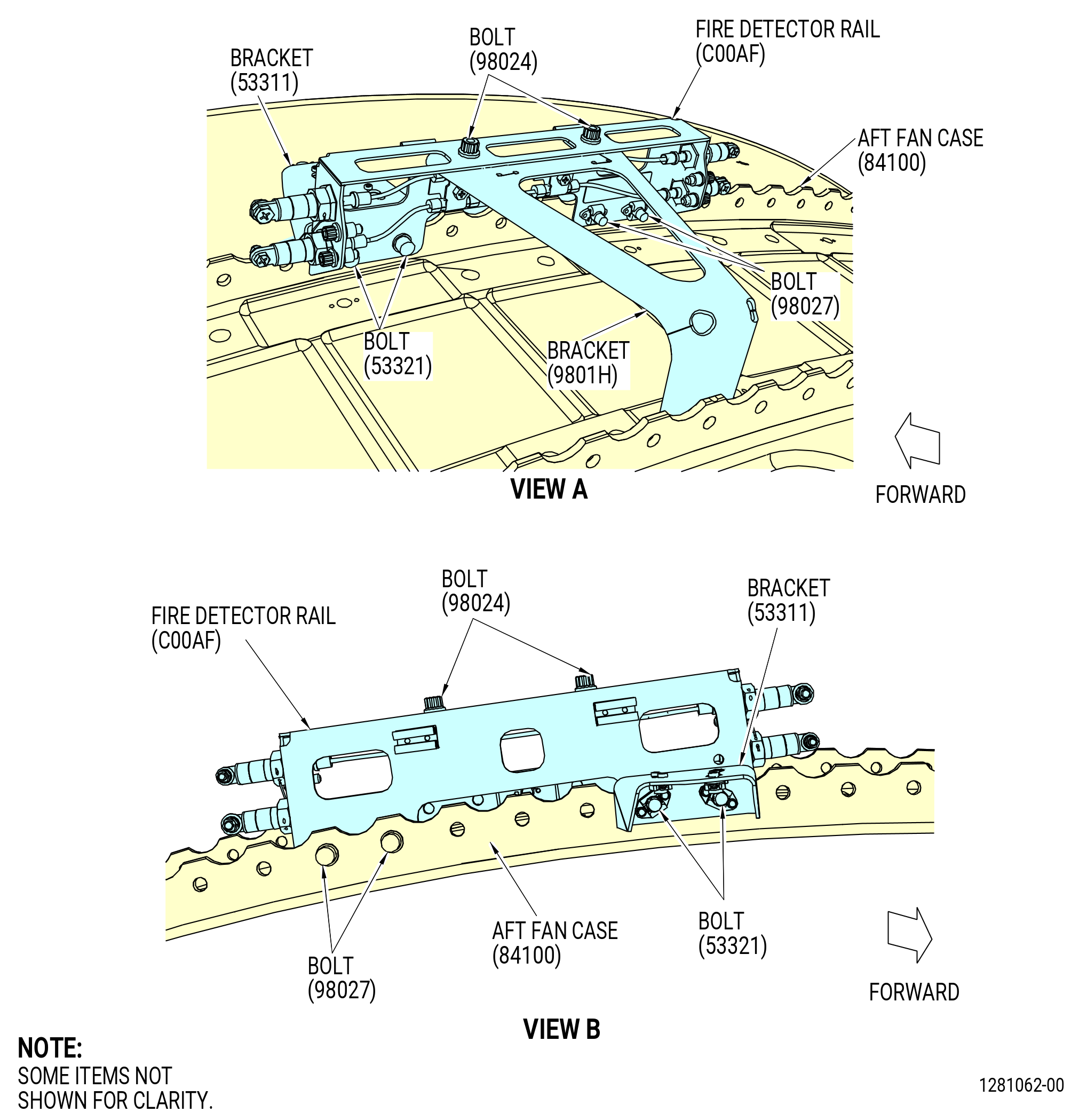
| C. | Remove the fire detection rail (C00AF) from the aft fan case as follows. Refer to Figure 504. |
| (1) | Remove the bolts (98024) that attach the fire detection rail to the bracket (9801H). |
| (2) | Remove the bolts (53321) that attach the fire detection to the bracket (53311). |
| (3) | Remove the bolts (98027) that attach the fire detection rail to the aft fan case. |
| (4) | Put the bolts (10-230 , 72-00-01) (SIN 53321) at the bracket (10-280 , 72-00-01) (SIN 53311) and tighten. |
| (5) | Remove the fire detection rail from the aft fan case. |
| (6) | Put the fire detection rail into storage in a plastic bag. |
|
|
| Subtask 72-00-00-030-225 |
| D. | Remove the lower bifurcation EBU (474339) as follows: |
| CAUTION: |
|
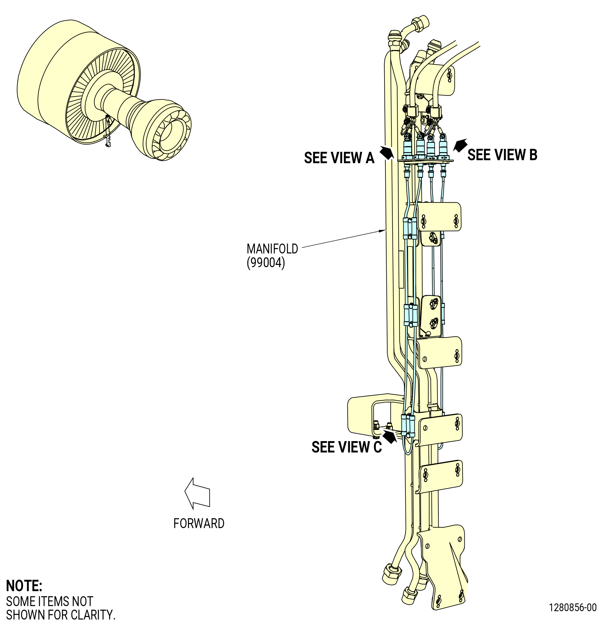
| (1) | Remove the right sensing element (C00A8) as follows. Refer to Figure 505. |
| (a) | If necessary, loosen the nuts (05-180 , 71-00-00) (SIN C00K3), remove the screws (05-140 , 71-00-00) (SIN C00F3) and washers (05-170 , 71-00-00) (SIN C00J0), and disconnect the terminals from the sensing elements and the W30 harness. |
| (b) | Loosen the six bolts (98023) and remove the clamps (C00V3) from the grommets (C00N7) in the sensing elements. |
| (c) | Loosen the nut connectors and remove the right sensing element from the manifold (99004). |
| (d) | Put the sensing element on a clean work surface. |
| (e) | Remove the six grommets from the sensing element. |
| (f) | Put the sensing element and hardware into storage in a plastic bag. |
| (2) | Remove the left sensing element (C00A9) as follows. Refer to Figure 505. |
| (a) | If necessary, loosen the nuts (C00K4), remove the screws (C00F4) and washers (C00J1), and disconnect the terminals from the sensing elements and the W31 harness. |
| (b) | Loosen the six bolts (98023) and remove the clamps (C00V3) from the grommets (C00N7) in the sensing elements. |
| (c) | Loosen the nut connectors and remove the left sensing element from the manifold (99004). |
| (d) | Put the sensing element on a clean work surface. |
| (e) | Remove the six grommets from the sensing element. |
| (f) | Put the sensing element and hardware into storage in a plastic bag. |
| Subtask 72-00-00-030-324 |
| * * * PRE SB 72-0322( Old Blankets and Support Brackets Configuration ) |
| * * * PRE SB 72-0071( Bifurcation Firewall Insulation Blanket without Support Strap ) |
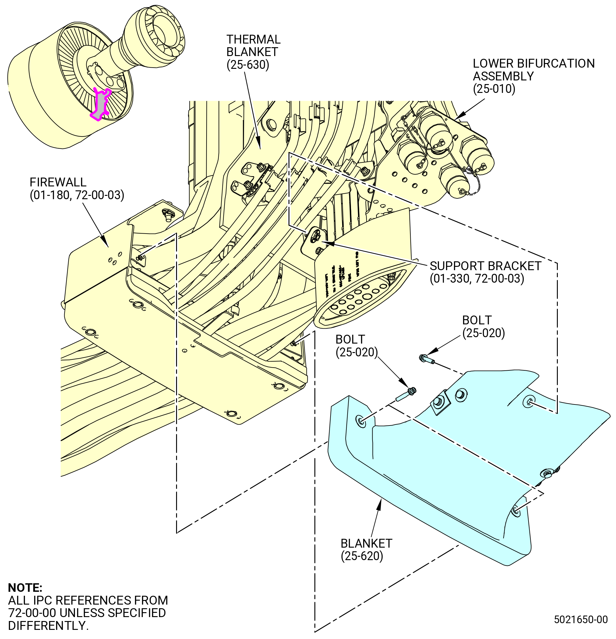
| E. | Remove the blanket (25-620) (SIN 09492). Refer to Figure 507 and do as follows: |
| (1) | Remove the safety wire from the three sets of lugs on the blanket. |
| (2) | Remove the three machine bolts (bolts) (25-020) (SIN 09422) that attach the blanket to the lower bifurcation firewall (firewall) (01-180 , 72-00-03) (SIN 09401) and support bracket (01-330 , 72-00-03) (SIN 09410) on the lower bifurcation assembly (25-010) (SIN 09400). |
| (3) | Remove the blanket. |
| * * * END PRE SB 72-0071 |
| Subtask 72-00-00-030-325 |
| * * * PRE SB 72-0223( Installation of the Blanket with Flexible Support Strap ) |
| * * * SB 72-0071( Bifurcation Firewall Insulation Blanket with Support Strap ) |
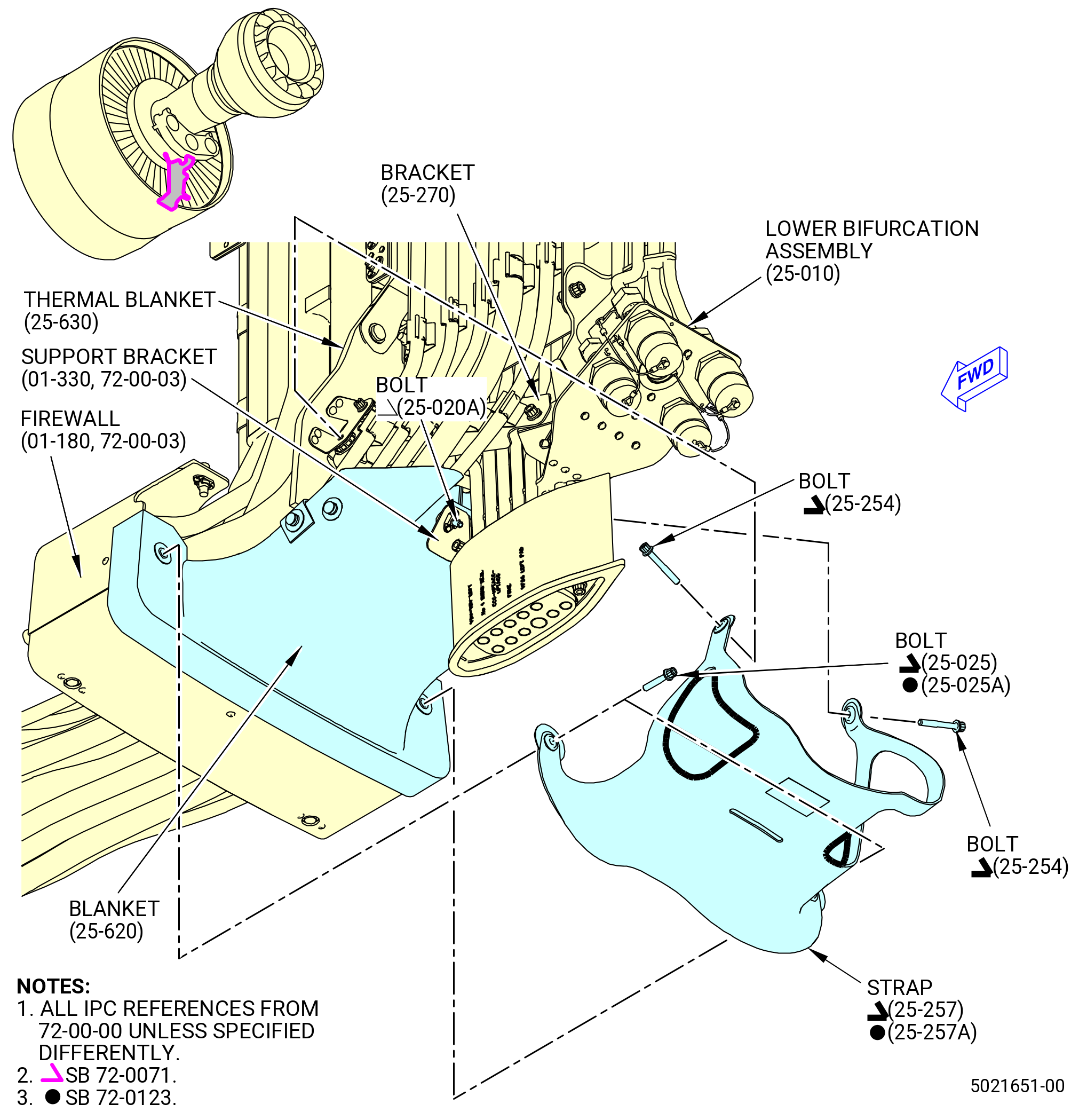
| E.A. | Remove the blanket (25-620) (SIN 09492) and support strap (strap) (25-257) (SIN 09494) or (25-257A) (SIN 09494). Refer to Figure 507 and do as follows: |
| (1) | Remove the safety wire from the three sets of lugs on the blanket. |
| (2) | Remove the two machine bolts (bolts) (25-254) (SIN 09424) that attach the strap to the thermal blanket (25-630) (SIN 09493) and support brackets (brackets) (25-270) (SIN 67115) and (25-300) (SIN 67116). |
| (3) | Remove the two machine bolts (bolts) (25-025) (SIN 09423) or (25-025A) (SIN 09423) that attach the strap and blanket to the firewall (01-180 , 72-00-03) (SIN 09401). |
| (4) | Remove the bolt (25-020A) (SIN 09422) that attaches the blanket and strap to the support bracket (01-330 , 72-00-03) (SIN 09410) on the lower bifurcation assembly (25-010) (SIN 09400). |
| (5) | Remove the strap and blanket. |
| * * * END SB 72-0071 |
| * * * END PRE SB 72-0223 |
| Subtask 72-00-00-030-326 |
| * * * SB 72-0223( Installation of the Blanket with Rigid Support Bracket ) |
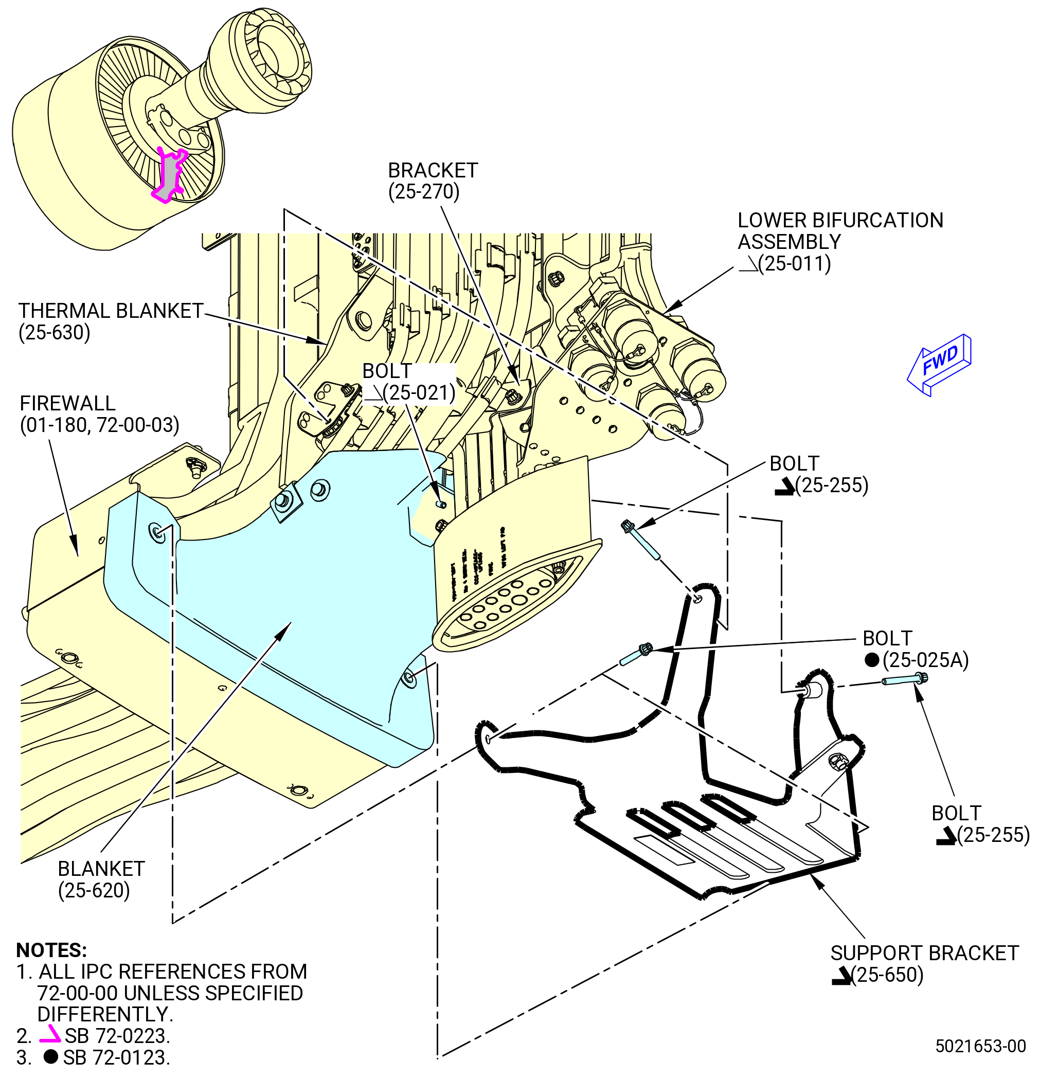
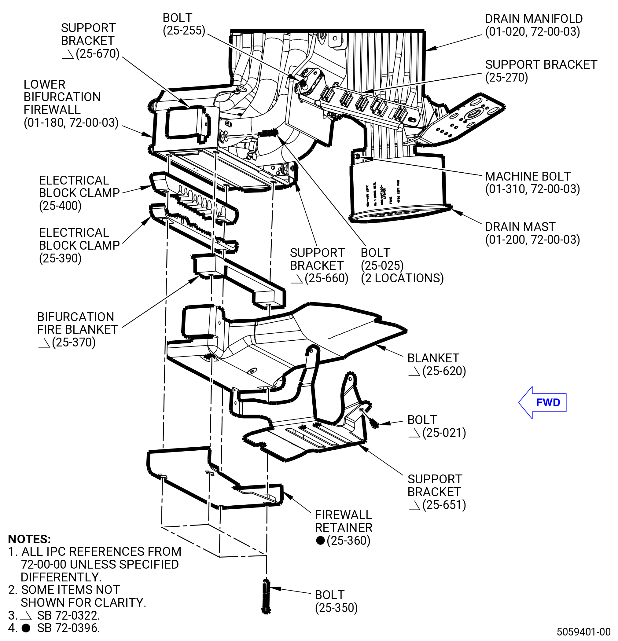
| E.B. | Remove the blanket (25-620) (SIN 09492) and support bracket (25-650) (SIN 09411). Refer to Figure 507 and do as follows: |
| (1) | Remove the safety wire from the three sets of lugs on the blanket. |
| (2) | Remove the two bolts (25-255) (SIN 09424) that attach the support bracket (25-650) (SIN 09411) to the thermal blanket (25-630) (SIN 09493) and brackets (25-270) (SIN 67115) and (25-300) (SIN 67116). |
| (3) | Remove the two bolts (25-025A) (SIN 09423) that attach the support bracket (25-650) (SIN 09411) and blanket to the firewall (01-180 , 72-00-03) (SIN 09401). |
| (4) | Remove the bolt (25-021) (SIN 09422) that attaches the support bracket (25-650) (SIN 09411) to the blanket. |
| (5) | Remove the support bracket (25-650) (SIN 09411) and blanket. |
| * * * END SB 72-0223 |
| Subtask 72-00-00-030-370 |
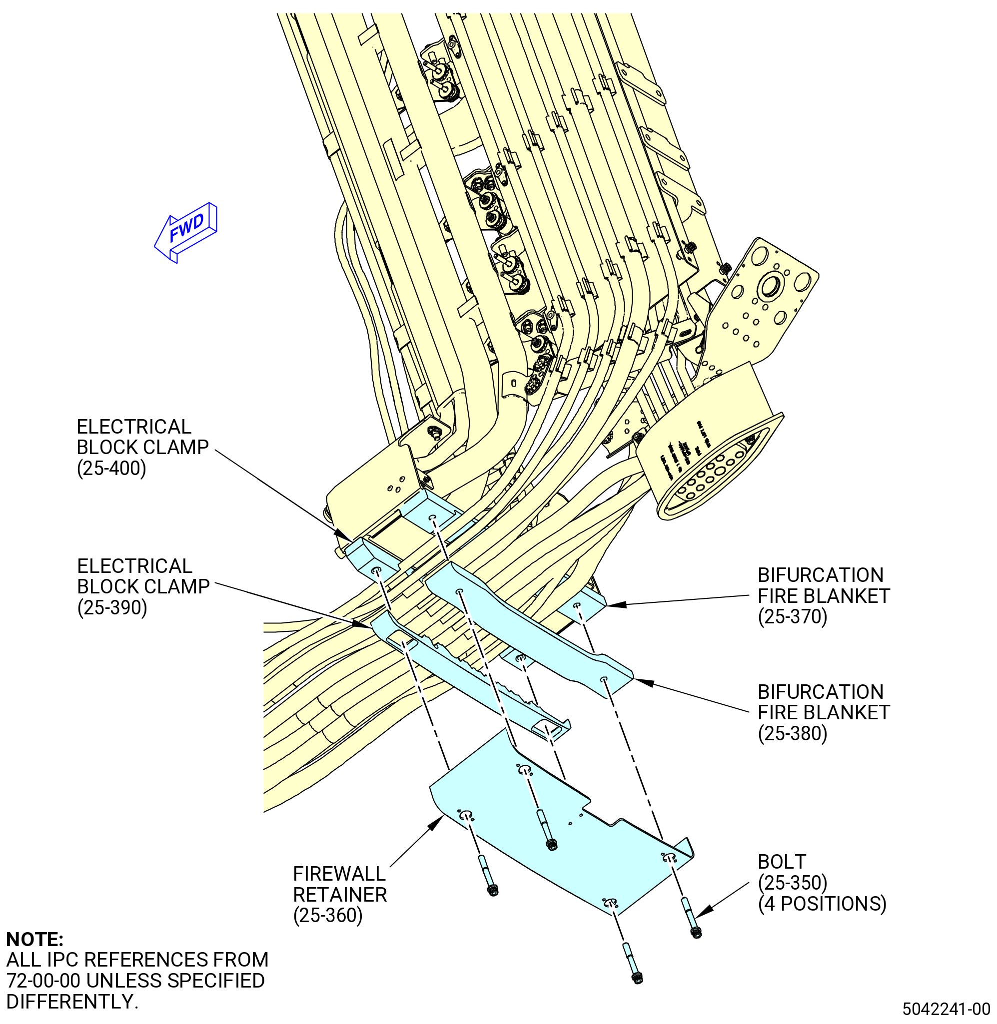
| F. | Remove the firewall retainer (25-360) (SIN 09403). Refer to Figure 506 and do as follows: |
| (1) | After the blanket (25-620) (SIN 09492) was removed, remove the four machine bolts (bolts) (25-350) (SIN 09421) that attach the firewall retainer (25-360) (SIN 09403) to the lower bifurcation firewall (01-180 , 72-00-03) (SIN 09401) thru the electrical block clamps (25-400) (SIN 09481) and (25-390) (SIN 09482) and the bifurcation fire blankets (25-380) (SIN 09490) and (25-370) (SIN 09491). |
| (2) | Remove the firewall retainer (25-360) (SIN 09403). |
| * * * END PRE SB 72-0322 |
| Subtask 72-00-00-030-371 |
| * * * SB 72-0322( New Blankets and Support Brackets Configuration ) |
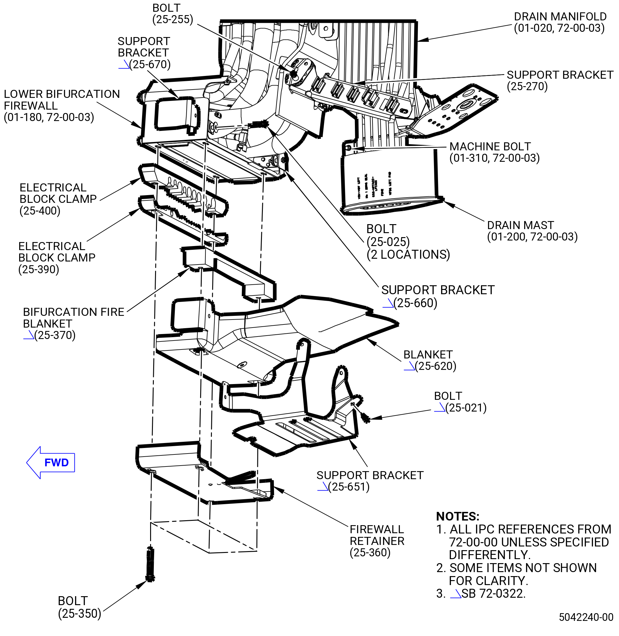
| G. | Remove the bifurcation fire blanket (25-370) (SIN 09491), the blanket (25-620) (SIN 09492), and the support brackets (25-651) (SIN 09411), (25-660) (SIN 09415), and (25-670) (SIN 09417). Refer to Figure 508 and do as follows: |
| (1) | Remove the machine bolt (bolt) (25-021) (SIN 09422) that attach the blanket (25-620) (SIN 09492) to the support bracket (25-651) (SIN 09411). |
| (2) | Remove the machine bolt (bolt) (25-025) (SIN 09423) that attach the support bracket (25-670) (SIN 09417), the support bracket (25-651) (SIN 09411), and the blanket (25-620) (SIN 09492) to the lower bifurcation firewall (01-180 , 72-00-03) (SIN 09401). |
| (3) | Remove the bolt (25-025) (SIN 09423) that attach the support bracket (25-660) (SIN 09415), the support bracket (25-651) (SIN 09411), and the blanket (25-620) (SIN 09492) to the lower bifurcation firewall (01-180 , 72-00-03) (SIN 09401). |
| (4) | Remove the support brackets (25-670) (SIN 09417) and (25-660) (SIN 09415). |
| (5) | Remove the bolt (25-255) (SIN 09424) that attach the support bracket (25-651) (SIN 09411) and the blanket thermal (25-630) (SIN 09493) to the support bracket (25-270) (SIN 67115). |
| (6) | Remove the bolt (25-255) (SIN 09424) that attach the support bracket (25-651) (SIN 09411) and the blanket thermal (25-630) (SIN 09493) to the support bracket (25-300) (SIN 67116). |
| (7) | Remove the support bracket (25-651) (SIN 09411). |
| (8) | Remove the four bolts (25-350) (SIN 09421) that attach the firewall retainer (25-360) (SIN 09403) to the lower bifurcation firewall (01-180 , 72-00-03) (SIN 09401) thru the electrical block clamps (25-400) (SIN 09481) and (25-390) (SIN 09482) and the bifurcation fire blanket (25-370) (SIN 09491) and the blanket (25-620) (SIN 09492). |
| (9) | Remove the firewall retainer (25-360) (SIN 09403). |
| (10) | Remove the blanket (25-620) (SIN 09492). |
| * * * END SB 72-0322 |
| Subtask 72-00-00-030-226 |
| CAUTION: |
|
| CAUTION: |
|
| NOTE: |
|
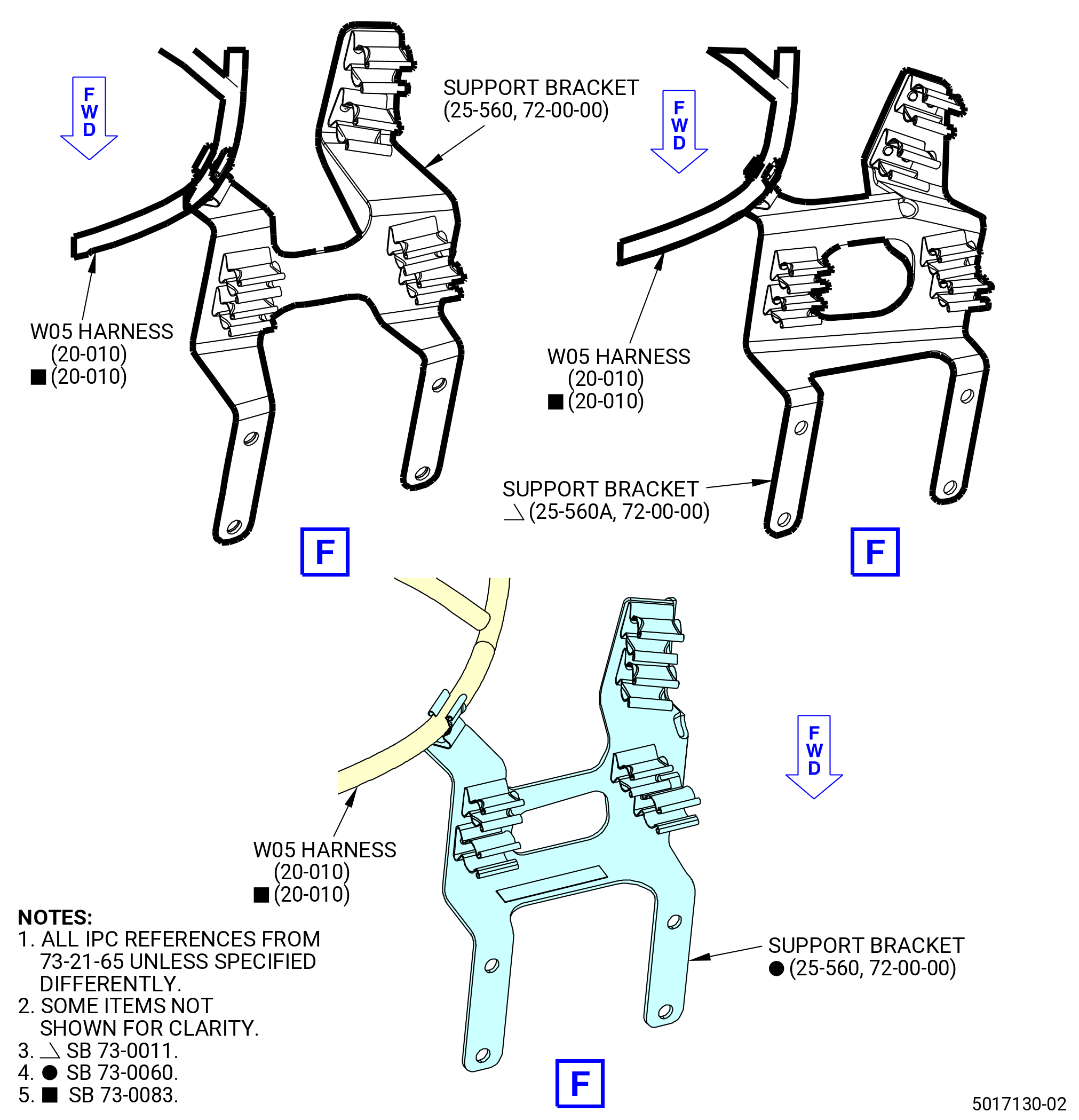
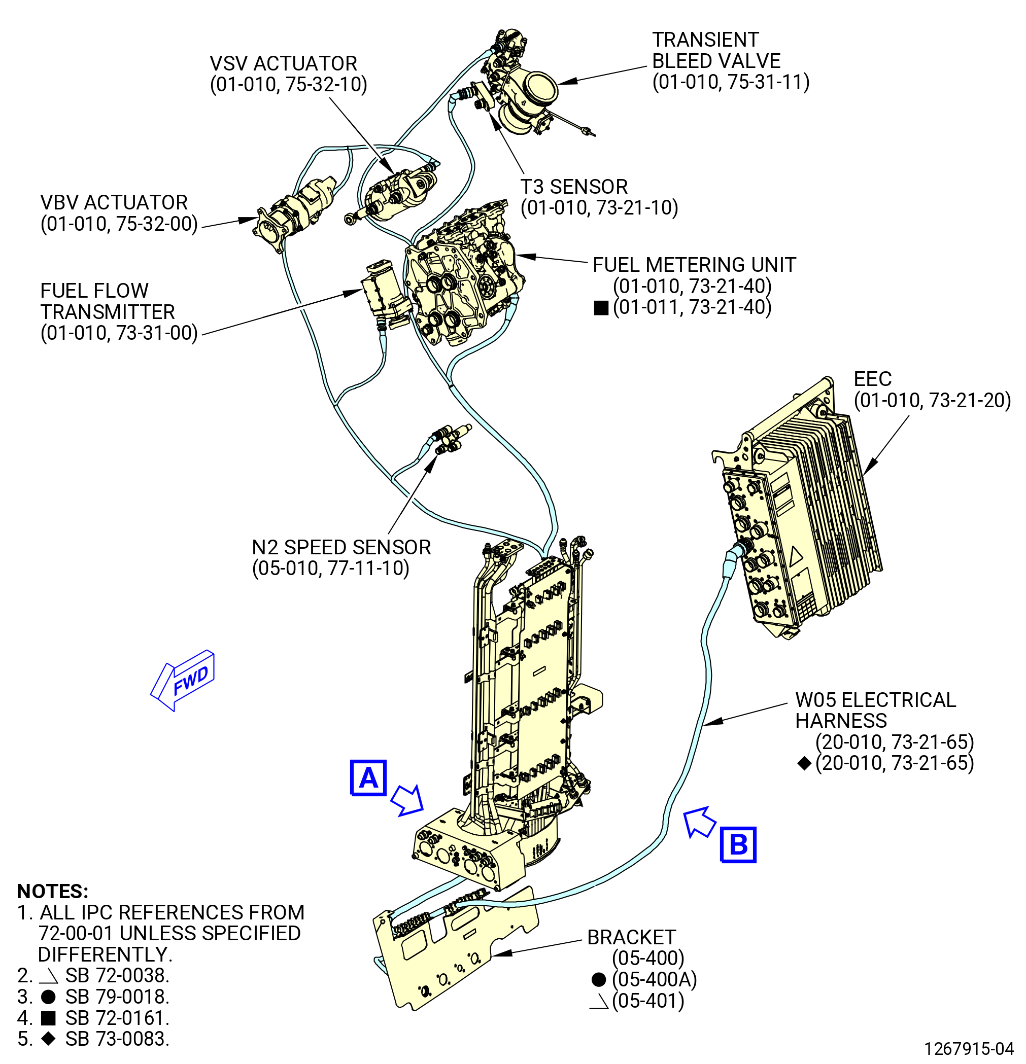
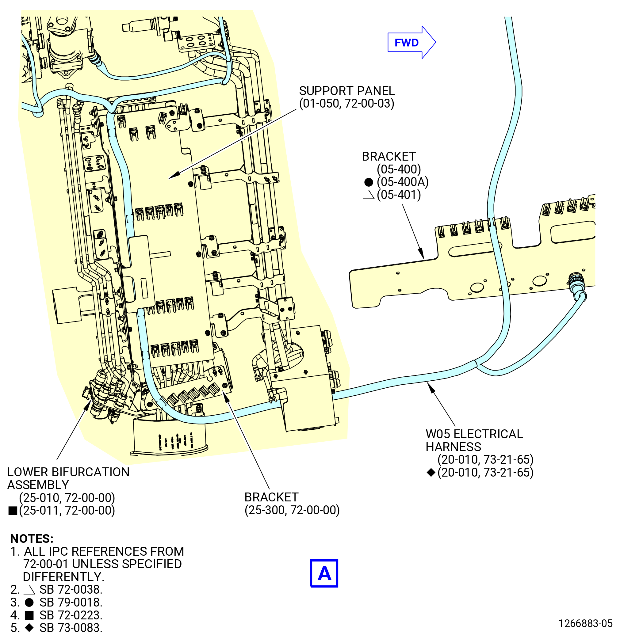
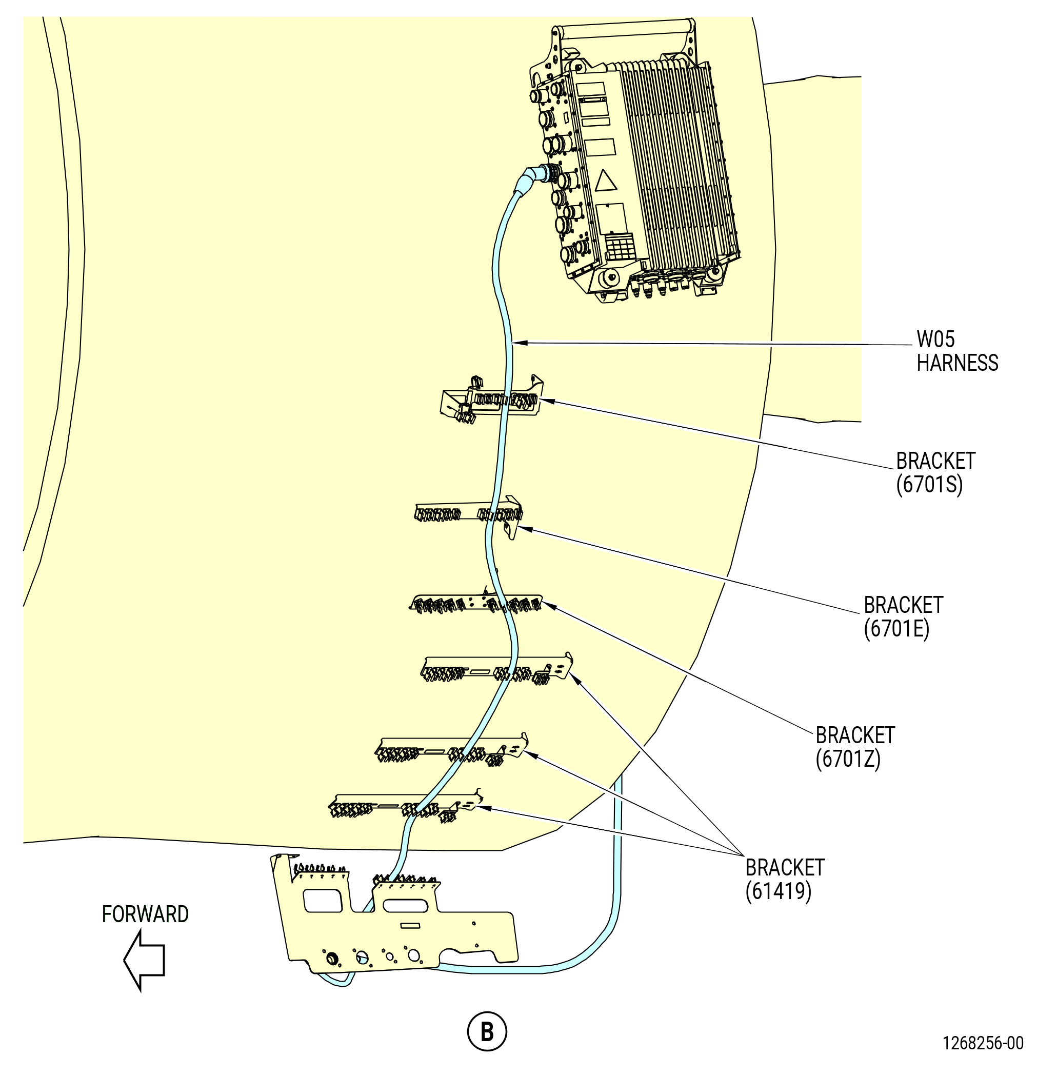
| H. | Remove the W05 electrical harness (20-010 , 73-21-65) (SIN 67004) from the propulsor. Refer to Figure 509 and do as follows: |
| (1) | Remove the W05 electrical harness from the spring clips on the brackets (05-300 , 72-00-01) (SIN 6701S), (05-330 , 72-00-01) (SIN 6701E), (07-470 , 72-00-01) (SIN 6701Z), (01-300 , 72-00-01) (SIN 61419), and (30-540 , 72-00-02) (SIN 6711D) or (30-541 , 72-00-02) (SIN 6711D). |
| Subtask 72-00-00-030-413 |
| * * * PRE SB 73-0074( Harness Support Spring Clips with Clip Inserts ) |
| (2) | Remove the clip insert (20-050 , 73-21-65) (SIN 67175) from bracket (30-540 , 72-00-02) (SIN 6711D) or (30-541 , 72-00-02) (SIN 6711D). |
| NOTE: |
|
| * * * END PRE SB 73-0074 |
| Subtask 72-00-00-030-414 |
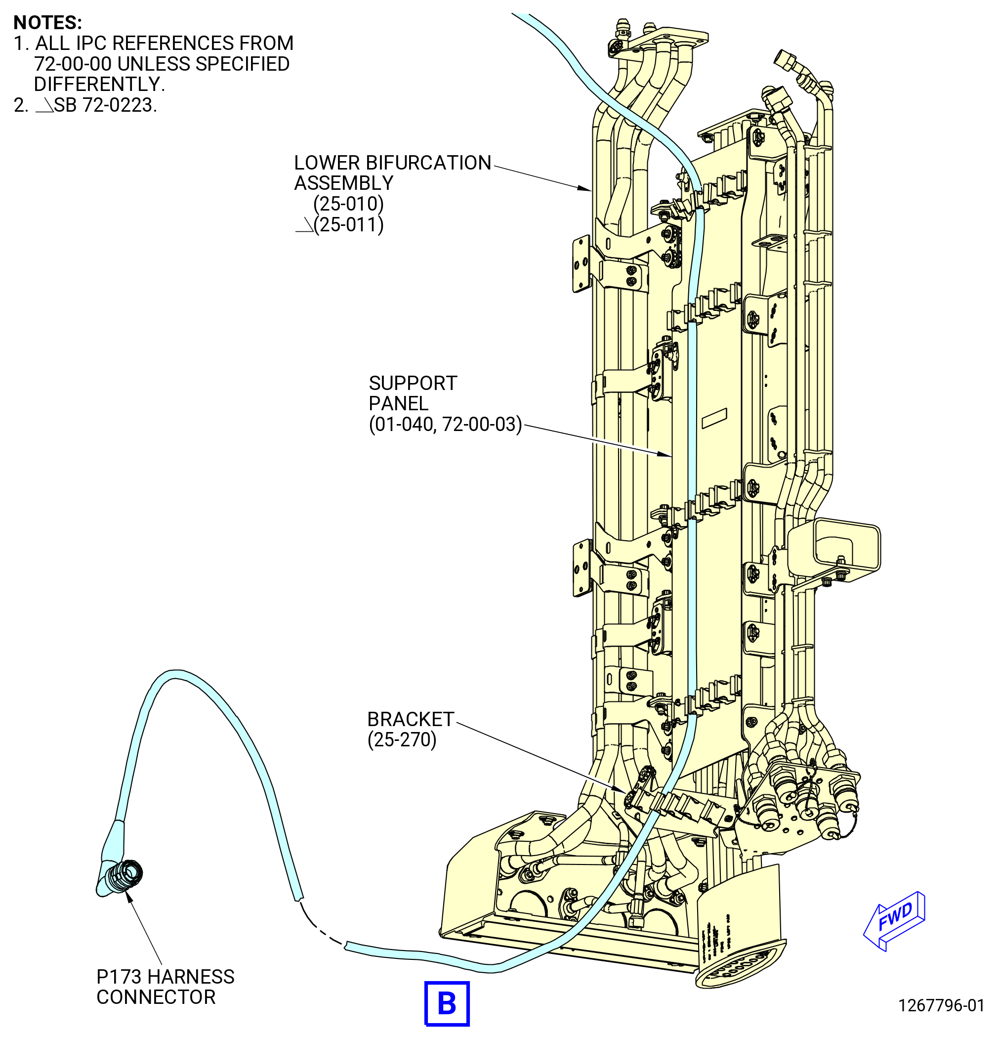
| (3) | Remove the W05 electrical harness from the spring clips on the right side cable shield (support panel) (01-050 , 72-00-03) (SIN 09711) and bracket (25-300) (SIN 67116) on the right side, aft looking forward (ALF), of the lower bifurcation assembly (25-010) (SIN 09400) or (25-011) (SIN 09400). |
| (4) | Remove the W05 electrical harness from the spring clips on the bracket (05-400 , 72-00-01) (SIN 6701F) or (05-401 , 72-00-01) (SIN 6701F). |
| (5) | Loosen and disconnect the W05 electrical harness connector (P5) from the EEC (65H00) receptacle (J5). |
| (6) | Loosen and disconnect the W05 electrical harness receptacle (J0519) from the W09 harness (40-010 , 73-21-65) (SIN 67008) connector (P0919) at the bracket (05-400 , 72-00-01) (SIN 6701F) or (05-401 , 72-00-01) (SIN 6701F). |
| (7) | Loosen and disconnect the W05 electrical harness connector (P057) from the N2 speed sensor (65D00) Channel A receptacle. |
| (8) | Loosen and disconnect the W05 electrical harness connector (P056) from the fuel flow transmitter (30800) receptacle. |
| (9) | Loosen and disconnect the W05 electrical harness connector (P054) from the VBV actuator (30700) receptacle. |
| (10) | Loosen and disconnect the W05 electrical harness connector (P053) from the VSV actuator (30400) receptacle. |
| (11) | Loosen and disconnect the W05 electrical harness connector (P059) from the fuel metering unit (01-010 , 73-21-40) (SIN 30000) or (01-011 , 73-21-40) (SIN 30000) receptacle. |
| (12) | Loosen and disconnect the W05 electrical harness connector (P055) from the T3 sensor (65N00) receptacle. |
| (13) | Remove the W05 electrical harness from the spring clips on the brackets (05-090 , 73-11-41) (SIN 37610), (05-090 , 73-11-40) (SIN 6881A), and (10-210 , 75-24-20) (SIN 38116) or (10-250 , 75-24-20) (SIN 38116). |
| (14) | Loosen and disconnect the W05 electrical harness connector (P058) from the transient bleed valve (60700) receptacle. |
| Subtask 72-00-00-030-227 |
| CAUTION: |
|
| CAUTION: |
|
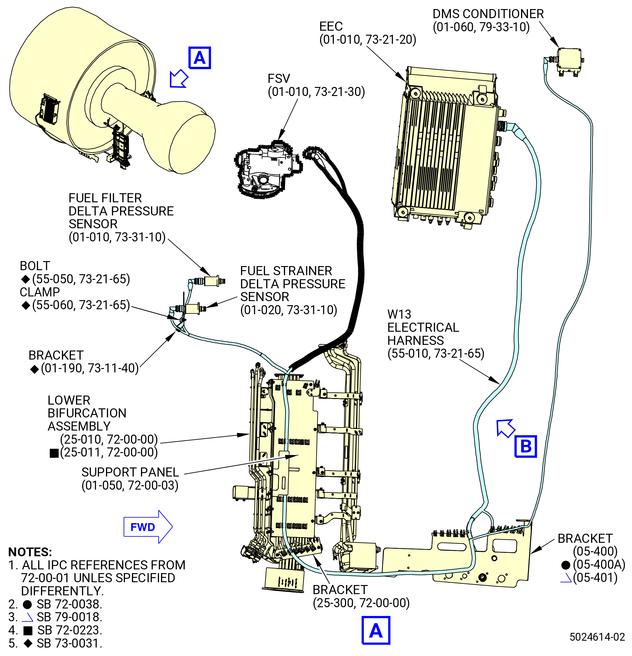
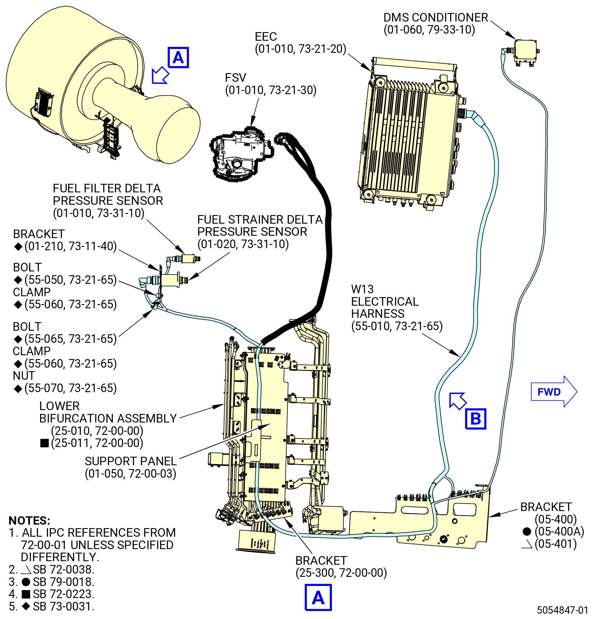
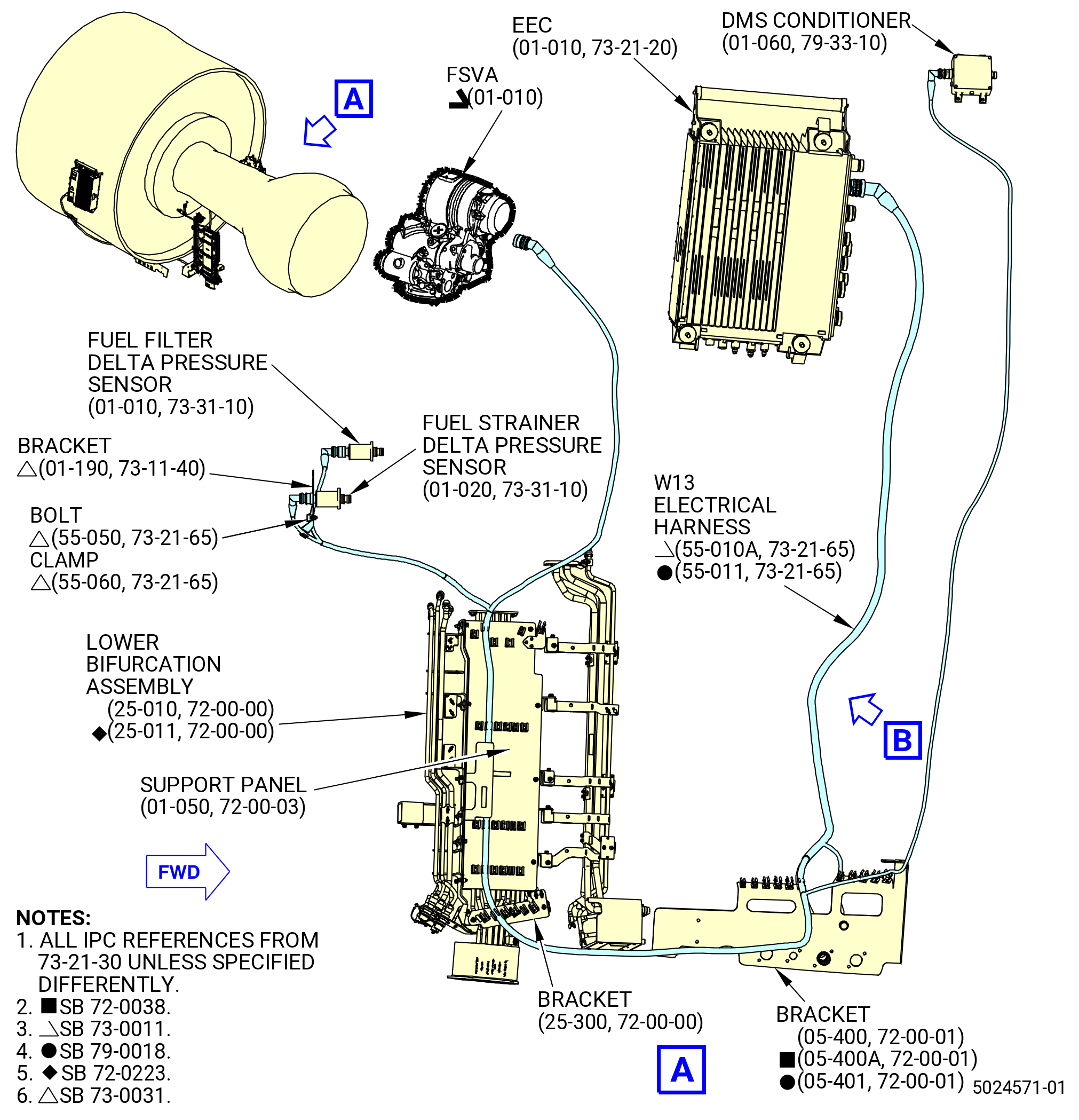
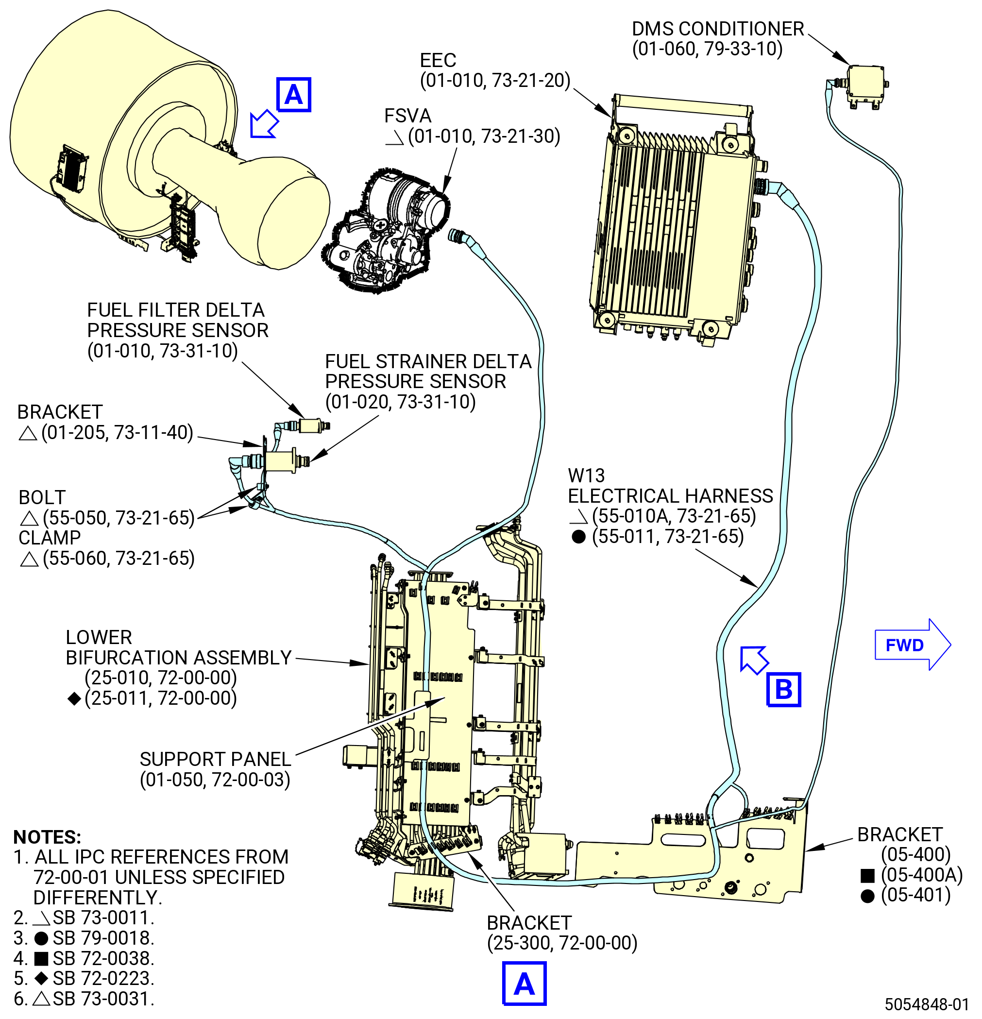
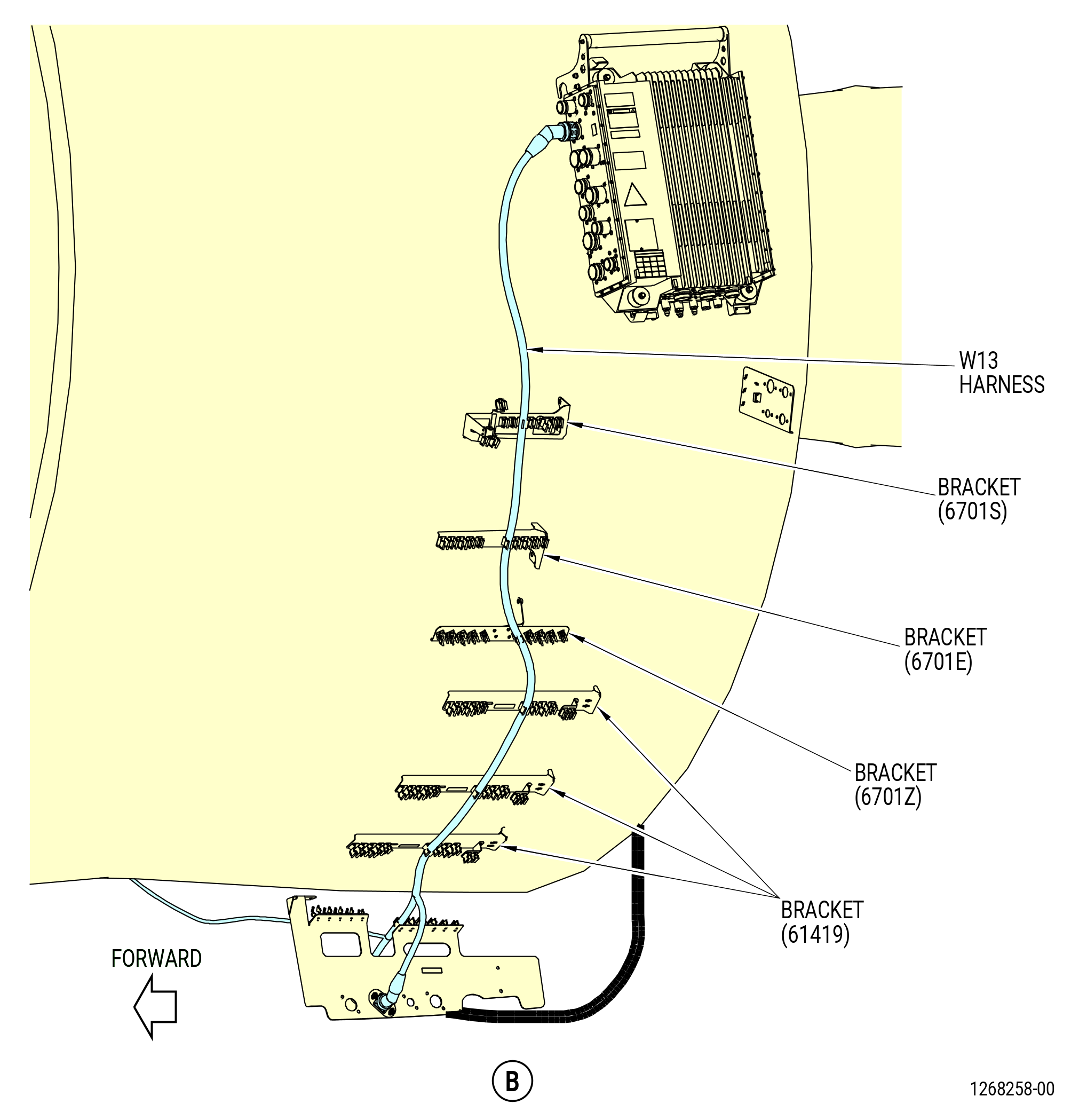
| I. | Remove the W13 electrical harness (harness) (55-010 , 73-21-65) (SIN 6700B) or (55-010A , 73-21-65) (SIN 6700B) or (55-011 , 73-21-65) (SIN 6700B) from the propulsor. Refer to Figure 510 and do as follows: |
| (1) | Remove the harness from the spring clips on the brackets (05-300 , 72-00-01) (SIN 6701S), (05-330 , 72-00-01) (SIN 6701E), (07-470 , 72-00-01) (SIN 6701Z), (01-300 , 72-00-01) (SIN 61419), and (30-540 , 72-00-02) (SIN 6711D) or (30-541 , 72-00-02) (SIN 6711D). |
| Subtask 72-00-00-030-415 |
| * * * PRE SB 73-0074( Harness Support Spring Clips with Clip Inserts ) |
| (2) | Remove the clip insert (55-020 , 73-21-65) (SIN 67175) from bracket (30-540 , 72-00-02) (SIN 6711D) or (30-541 , 72-00-02) (SIN 6711D). |
| NOTE: |
|
| * * * END PRE SB 73-0074 |
| Subtask 72-00-00-030-416 |
| (3) | Remove the W13 electrical harness from the spring clips on the support panel (01-050 , 72-00-03) (SIN 09711) and bracket (25-300) (SIN 67116) on the right side, ALF, of the lower bifurcation assembly (25-010) (SIN 09400) or (25-011) (SIN 09400). |
| (4) | Remove the harness from the spring clips on the bracket (05-400 , 72-00-01) (SIN 6701F) or (05-401 , 72-00-01) (SIN 6701F). |
| Subtask 72-00-00-030-329 |
| * * * SB 73-0031( Removal of W13 Harness with additional Bracket ) |
| (5) | Remove the harness from the W13 harness electrical bracket (bracket) (01-190 , 73-11-40) (SIN 6741N). |
| NOTE: |
|
| (a) | Remove the harness from the clip of the bracket. |
| (b) | Remove the bolt (55-050 , 73-21-65) (SIN 6702A) and cushion loop clamp (clamp) (55-060 , 73-21-65) (SIN 6708E) that attach the harness to the bracket. |
| * * * END SB 73-0031 |
| Subtask 72-00-00-030-376 |
| * * * SB 73-0031( Removal of W13 Harness from New Bracket with Two Clamps Attach Positions - Production Option ) |
| (5).A. | Remove the harness from the bracket (01-205 , 73-11-40) (SIN 6741N) as follows: |
| NOTE: |
|
| (a) | Remove the two bolts (55-050 , 73-21-65) (SIN 6702A) and cushion loop clamps (clamps) (55-060 , 73-21-65) (SIN 6708E) that attach the harness to the bracket. |
| * * * END SB 73-0031 |
| Subtask 72-00-00-030-377 |
| * * * SB 73-0031( Removal of W13 Harness from New Bracket with Two Clamps Attach Positions - Field Option ) |
| (5).B. | Remove the harness from the bracket (01-205 , 73-11-40) (SIN 6741N) as follows: |
| NOTE: |
|
| (a) | Remove the two clamps (55-060 , 73-21-65) (SIN 6708E) and two bolts (55-050 , 73-21-65) (SIN 6702A) or one clamp (55-060 , 73-21-65) (SIN 6708E) with one bolt (55-050 , 73-21-65) (SIN 6702A) and one clamp (55-060 , 73-21-65) (SIN 6708E) with one double hexagon head machine bolt (bolt) (55-065 , 73-21-65) (SIN 67429) that attach the W13 harness to the bracket (01-205 , 73-11-40) (SIN 6741N). |
| * * * END SB 73-0031 |
| Subtask 72-00-00-030-378 |
| * * * SB 73-0031( Removal of W13 Harness from Bracket with Two Clamps Attach Positions - Reworked Option ) |
| (5).C. | Remove the harness from the bracket (01-210 , 73-11-40) (SIN 6741N) as follows: |
| NOTE: |
|
| (a) | Remove the two clamps (55-060 , 73-21-65) (SIN 6708E) and two bolts (55-050 , 73-21-65) (SIN 6702A) or one clamp (55-060 , 73-21-65) (SIN 6708E) with one bolt (55-050 , 73-21-65) (SIN 6702A) and one clamp (55-060 , 73-21-65) (SIN 6708E) with one bolt (55-065 , 73-21-65) (SIN 67429) one self-locking nut (nut) (55-070 , 73-21-65) (SIN 67441) that attach the W13 harness to the reworked bracket (01-210 , 73-11-40) (SIN 6741N). |
| * * * END SB 73-0031 |
| Subtask 72-00-00-030-330 |
| (6) | Loosen and disconnect the harness connector (P13) from the EEC (65H00) receptacle (J13). |
| (7) | Remove the bolts and the harness receptacle (J1303) from the W12 electrical harness (50-010 , 73-21-65) (SIN 6700A) or (50-011 , 73-21-65) (SIN 6700A) connector (P1203) at the bracket (05-400 , 72-00-01) (SIN 6701F) or (05-401 , 72-00-01) (SIN 6701F). |
| (8) | Loosen and disconnect the harness connector (P133) from the fuel filter delta pressure sensor (31500) receptacle. |
| (9) | Loosen and disconnect the harness connector (P135) from the fuel strainer delta pressure sensor (31501) receptacle. |
| (10) | Loosen and disconnect the harness connector (P134) from the flow splitting valve (FSV) or flow splitting valve accumulator (FSVA) (01-010 , 73-21-30) (SIN 31700) receptacle. |
| Subtask 72-00-00-030-303 |
| * * * PRE SB 73-0011( Engines without Fuel Vapor Accumulator ) |
| (11) | Remove the W13 harness (55-010 , 73-21-65) (SIN 6700B) connector (P137) from the fuel manifold temperature sensor (temp sensor) (01-010 , 73-31-05) (SIN 65T01) that attaches it to the hose tube (05-010 , 73-11-40) (SIN 34100). |
| NOTE: |
|
| * * * END PRE SB 73-0011 |
| Subtask 72-00-00-030-304 |
| (12) | Loosen and disconnect the harness connector (P132) from the debris monitoring system (DMS) conditioner (42500) receptacle. |
| Subtask 72-00-00-030-228 |
| CAUTION: |
|
| CAUTION: |
|
| NOTE: |
|
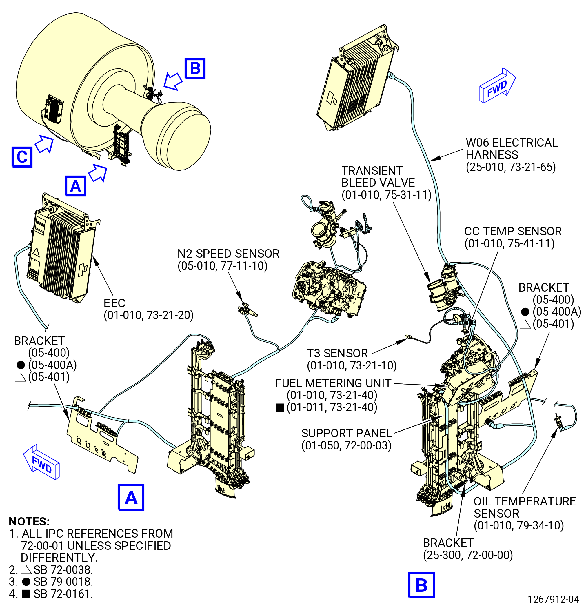
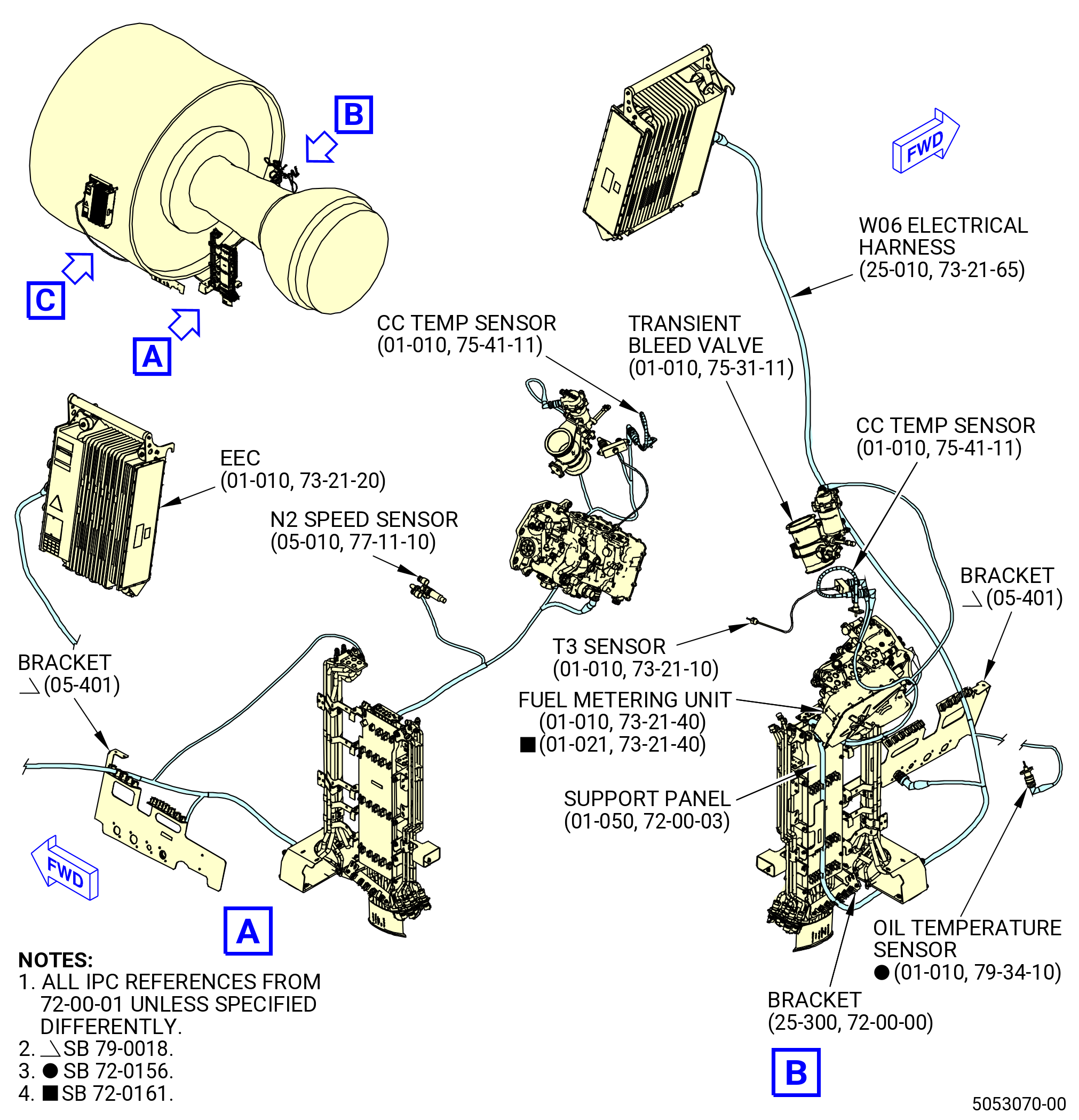
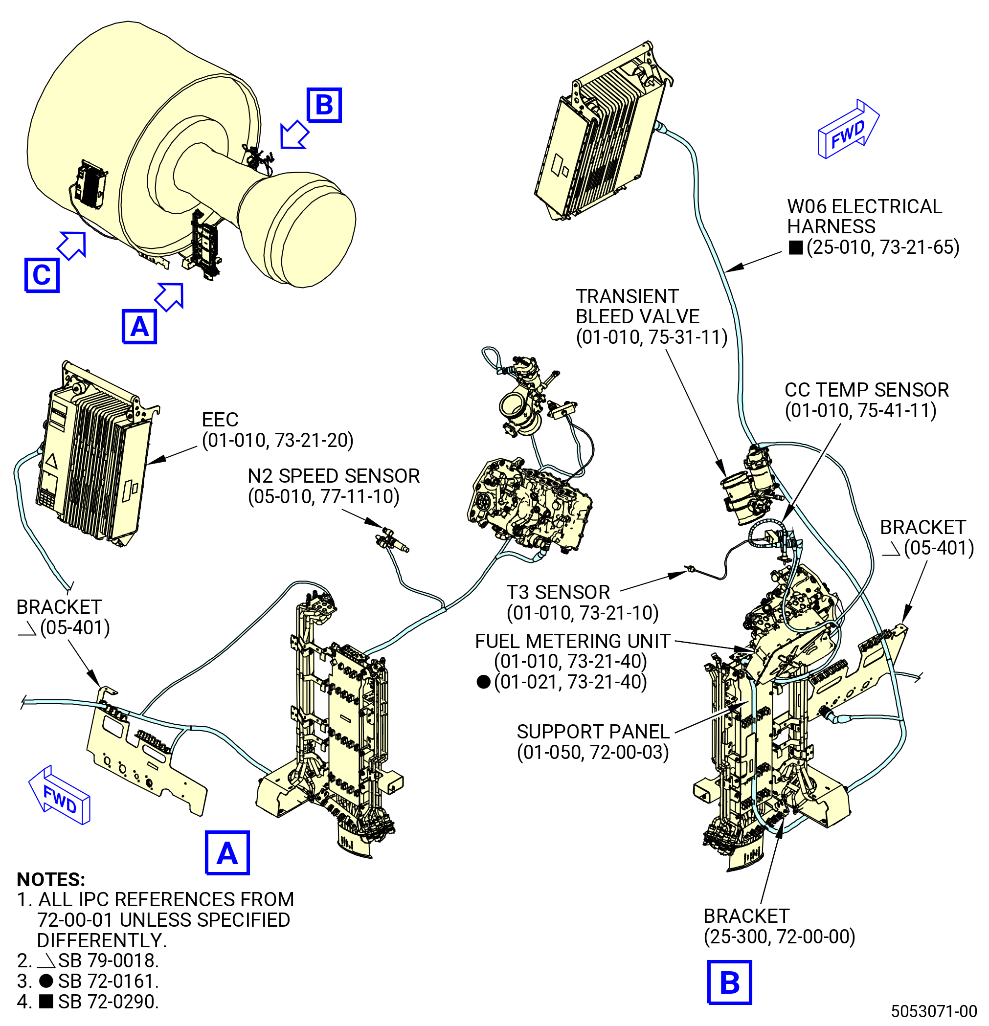
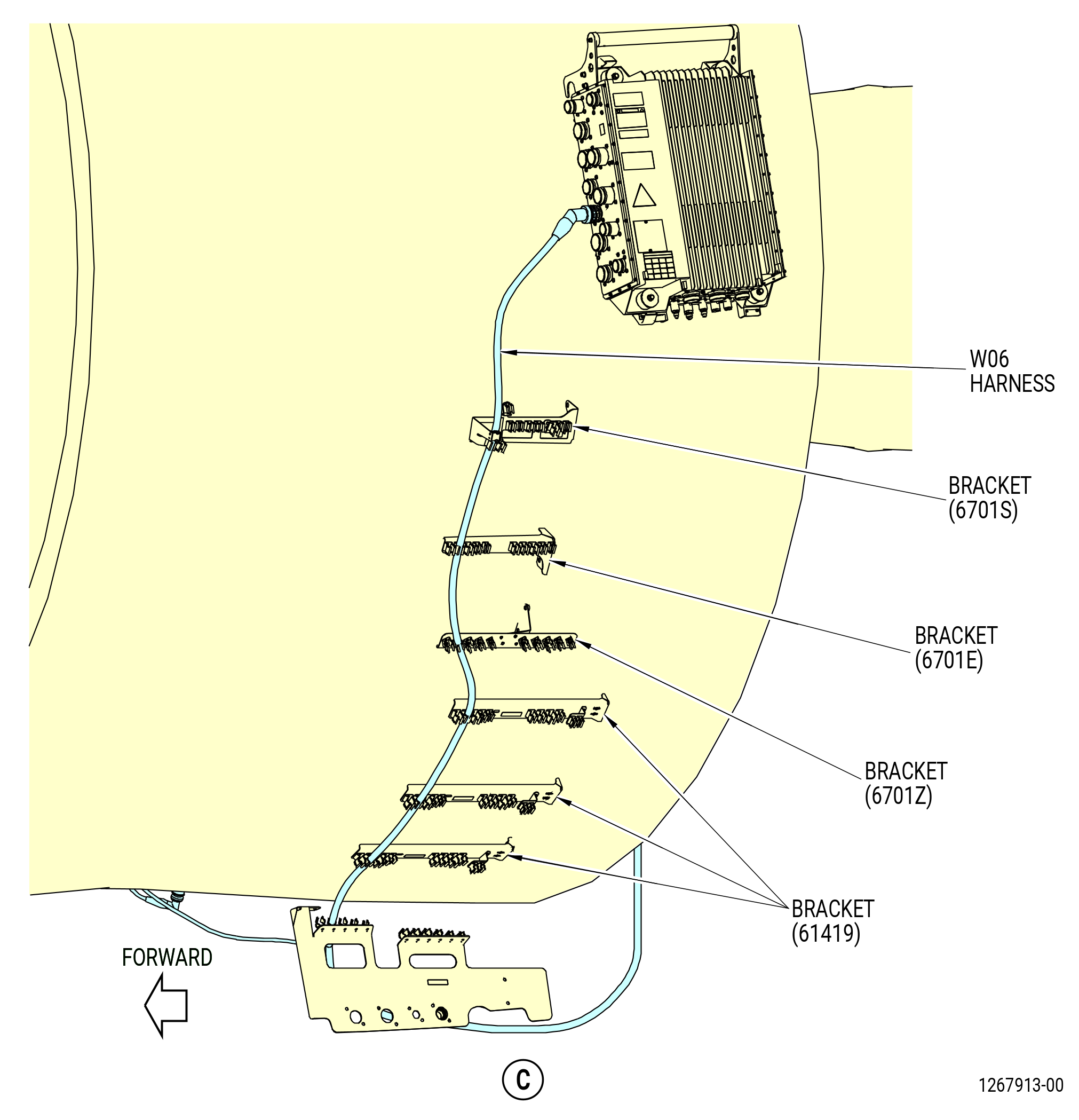
| J. | Remove the W06 electrical harness (harness) (67005) from the propulsor as follows. Refer to Figure 511. |
| (1) | Remove the W06 electrical harness from the spring clips on the brackets (6701S, 6701E, 6701Z, 61419). |
| (2) | Remove the W06 electrical harness from the spring clips on the support panel (01-050 , 72-00-03) (SIN 09711) and bracket (25-300) (SIN 67116) on the right side, ALF, of the lower bifurcation assembly (25-010) (SIN 09400) or (25-011) (SIN 09400). |
| (3) | Remove the W06 electrical harness from the spring clips on the bracket (05-400 , 72-00-01) (SIN 6701F) or (05-401 , 72-00-01) (SIN 6701F). |
| (4) | Loosen and disconnect the W06 electrical harness connector (P6) from the EEC (65H00) receptacle (J6). |
| (5) | Loosen and disconnect the W06 electrical harness connector (P1021) from the W10 harness (45-010 , 73-21-65) (SIN 67009) receptacle (J0621) at the bracket (05-400 , 72-00-01) (SIN 6701F) or (05-401 , 72-00-01) (SIN 6701F). |
| Subtask 72-00-00-030-372 |
| * * * FOR 1B/P/G03.1B/P/G04.1B/P1/G01 |
| * * * PRE SB 72-0290( Engine with Temperature Sensor ) |
| (6) | Loosen and disconnect the W06 electrical harness connector (P062) from the oil temperature sensor (01-010 , 79-34-10) (SIN 40800) receptacle. |
| NOTE: |
|
| * * * END PRE SB 72-0290 |
| Subtask 72-00-00-440-148 |
| * * * FOR ALL PIP 2 |
| * * * SB 72-0156( Engines with Temperature Sensor ) |
| (6).A. | Loosen and disconnect the W06 electrical harness connector (P062) from the oil temperature sensor (01-010 , 79-34-10) (SIN 40800) receptacle. |
| NOTE: |
|
| * * * END SB 72-0156 |
| Subtask 72-00-00-030-373 |
| * * * FOR ALL |
| (7) | Loosen and disconnect the W06 electrical harness connector (P064) from the N2 speed sensor (05-010 , 77-11-10) (SIN 65D00) receptacle. |
| (8) | Loosen and disconnect the W06 electrical harness connector (P087) from the fuel metering unit (01-010 , 73-21-40) (SIN 30000) or (01-011 , 73-21-40) (SIN 30000) receptacle. |
| (9) | Loosen and disconnect the W06 electrical harness connector (P063) from the T3 sensor (01-010 , 73-21-10) (SIN 65N00) receptacle. |
| Subtask 72-00-00-030-374 |
| * * * PRE SB 72-0290( Engines with Temperature Sensor ) |
| (10) | Loosen and disconnect the W06 electrical harness connector (P065) from the CC temp sensor (01-010 , 75-41-11) (SIN 65T00) receptacle. |
| NOTE: |
|
| * * * END PRE SB 72-0290 |
| Subtask 72-00-00-030-375 |
| (11) | Remove the W06 electrical harness from the spring clips on the brackets (05-090 , 73-11-41) (SIN 37610), (05-090 , 73-11-40) (SIN 6881A), and (10-210 , 75-24-20) (SIN 38116) or (10-250 , 75-24-20) (SIN 38116). |
| (12) | Loosen and disconnect the W06 electrical harness connector (P066) from the transient bleed valve (60700) receptacle. |
|
|
|
|
| Subtask 72-00-00-030-229 |
| * * * PRE SB 79-0018( MFOHX without Indicating Capability ) |
| CAUTION: |
|
| CAUTION: |
|
| NOTE: |
|
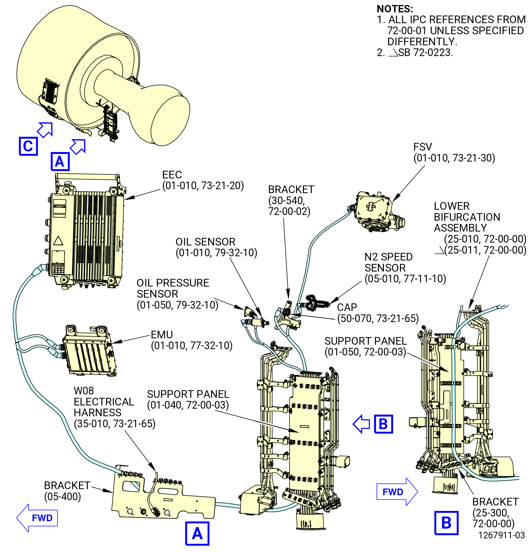
| K. | Remove the W12 electrical harness (50-010 , 73-21-65) (SIN 6700A) from the propulsor. Refer to Figure 512 and do as follows: |
| (1) | Remove the W12 electrical harness from the spring clips on the brackets (6701S, 6701E, 6701Z, 61419). |
| (2) | Remove the W12 electrical harness from the spring clips on the support panel (01-050 , 72-00-03) (SIN 09711) and bracket (25-300) (SIN 67116) on the right side, ALF, of the lower bifurcation assembly (25-010) (SIN 09400) or (25-011) (SIN 09400). |
| (3) | Remove the W12 electrical harness from the spring clips on the brackets (05-400 , 72-00-01) (SIN 6701F) and (30-540 , 72-00-02) (SIN 6711D). |
| (4) | Loosen and disconnect the W12 electrical harness receptacle (J1223) from the W08 electrical harness connector (P0823) at the bracket (05-400 , 72-00-01) (SIN 6701F). |
| (5) | Loosen and disconnect the W12 electrical harness connector (P12) from the EEC (65H00) receptacle (J12). |
| (6) | Loosen and disconnect the W12 electrical harness connector (P1221) from the EMU (65Z00) receptacle (J21). |
| (7) | Loosen and disconnect the W12 electrical harness connector (P1218) from the EMU receptacle (J18). |
| (8) | Remove the cap (50-070 , 73-21-65) (SIN 67090) large bolts from the harness bulkhead and bracket (30-540 , 72-00-02) (SIN 6711D) and disconnect the W12 electrical harness receptacle (J120) from the bracket and EMU interface. |
| (9) | Loosen and disconnect the W12 electrical harness connector (P122) from the oil pressure sensor (40501) receptacle. |
| (10) | Loosen and disconnect the W12 electrical harness connector (P123) from the oil filter DP sensor (oil sensor) (40500) receptacle. |
| (11) | Loosen and disconnect the W12 electrical harness connector (P125) from the N2 speed sensor (65D00) receptacle. |
| (12) | Loosen and disconnect the W12 electrical harness connector (P124) from the FSV or FSVA (01-010 , 73-21-30) (SIN 31700) receptacle. |
| * * * END PRE SB 79-0018 |
| Subtask 72-00-00-030-310 |
| * * * SB 79-0018( MFOHX with Indicating Capability ) |
| CAUTION: |
|
| CAUTION: |
|
| NOTE: |
|
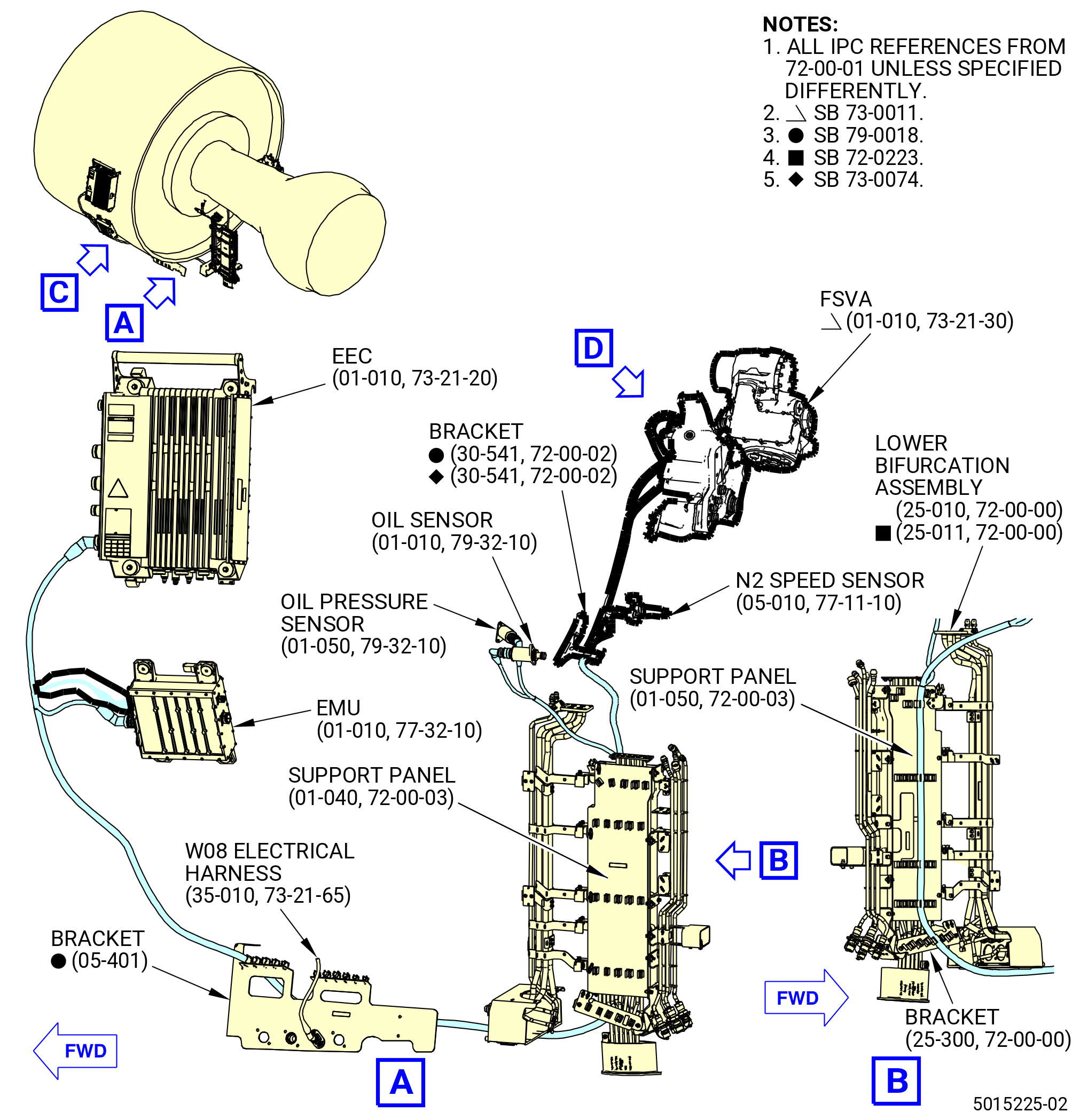
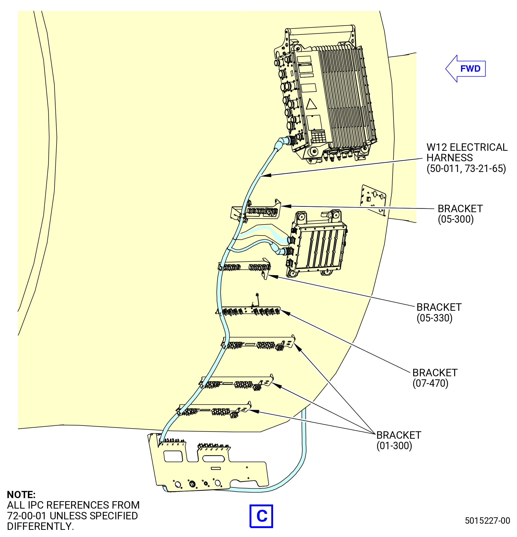
| K.A. | Remove the W12 electrical harness (50-011 , 73-21-65) (SIN 6700A) from the propulsor. Refer to Figure 512 and do as follows: |
| (1) | Remove the W12 electrical harness from the spring clips on the brackets (05-300 , 72-00-01) (SIN 6701S), (05-330 , 72-00-01) (SIN 6701E), (07-470 , 72-00-01) (SIN 6701Z), (01-300 , 72-00-01) (SIN 61419). |
| (2) | Remove the W12 electrical harness from the spring clips on the support panel (01-050 , 72-00-03) (SIN 09711) and bracket (25-300) (SIN 67116) on the right side, ALF, of the lower bifurcation assembly (25-010) (SIN 09400) or (25-011) (SIN 09400). |
| (3) | Remove the W12 electrical harness from the spring clips on the brackets (05-401 , 72-00-01) (SIN 6701F) and (30-541 , 72-00-02) (SIN 6711D). |
| Subtask 72-00-00-030-417 |
| * * * PRE SB 73-0074( Harness Support Spring Clips with Clip Inserts ) |
| (4) | Remove the clip insert (50-021 , 73-21-65) (SIN 67176) from bracket (30-541 , 72-00-02) (SIN 6711D). |
| NOTE: |
|
| * * * END PRE SB 73-0074 |
| Subtask 72-00-00-030-418 |
| (5) | Loosen and disconnect the W12 electrical harness receptacle (J1223) from the W08 electrical harness connector (P0823) at the bracket (05-401 , 72-00-01) (SIN 6701F). |
| (6) | Loosen and disconnect the W12 electrical harness connector (P12) from the EEC (01-010 , 73-21-20) (SIN 65H00) receptacle (J12). |
| (7) | Loosen and disconnect the W12 electrical harness connector (P1218) from the EMU receptacle (J18). |
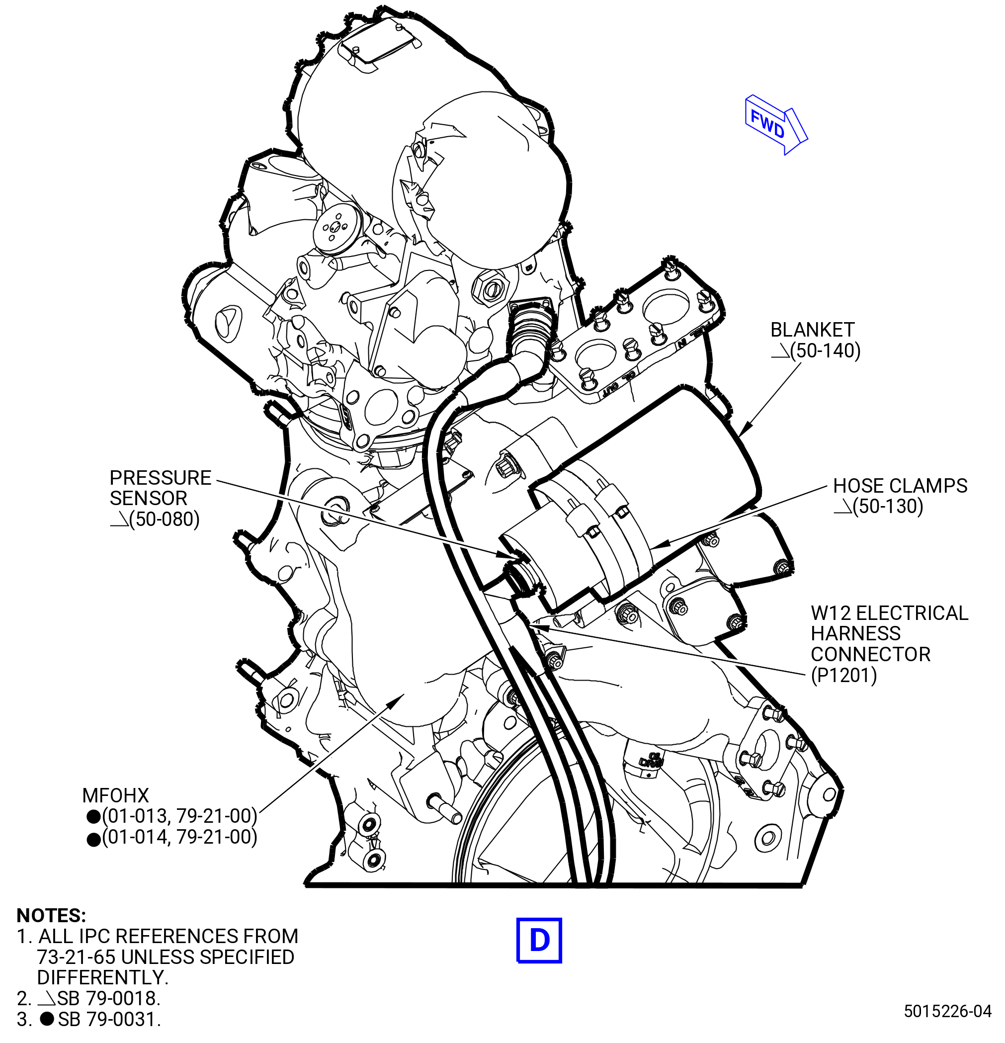
| (8) | Loosen and disconnect the W12 electrical harness connector (P1201) as follows: |
| (a) | Remove the two hose clamps (50-130 , 73-21-65) (SIN 31581) that attach the delta pressure sensor thermal insulation blanket (blanket) (50-140 , 73-21-65) (SIN 31590) to the pressure sensor (50-080 , 73-21-65) (SIN 31502). |
| (b) | Remove the blanket from the pressure sensor. |
| Subtask 72-00-00-030-345 |
| * * * PRE SB 79-0031( MFOHX without Improved Fuel Valve Guide ) |
| (c) | Loosen and disconnect the W12 electrical harness connector (P1201) from the pressure sensor that is on the main fuel oil heat exchanger (MFOHX) (01-011 , 79-21-00) (SIN 40700) or (01-012 , 79-21-00) (SIN 40700). |
| * * * END PRE SB 79-0031 |
| Subtask 72-00-00-030-346 |
| * * * SB 79-0031( MFOHX with Improved Fuel Valve Guide ) |
| (c).A. | Loosen and disconnect the W12 electrical harness connector (P1201) from the pressure sensor that is on the MFOHX (01-013 , 79-21-00) (SIN 40700) or (01-014 , 79-21-00) (SIN 40700). |
| * * * END SB 79-0031( ) |
| Subtask 72-00-00-030-347 |
| (9) | Loosen and disconnect the W12 electrical harness connector (P122) from the oil pressure sensor (01-050 , 79-32-10) (SIN 40501) receptacle. |
| (10) | Loosen and disconnect the W12 electrical harness connector (P123) from the oil filter DP sensor (oil sensor) (01-010 , 79-32-10) (SIN 40500) receptacle. |
| (11) | Loosen and disconnect the W12 electrical harness connector (P125) from the N2 speed sensor (05-010 , 77-11-10) (SIN 65D00) receptacle. |
| (12) | Loosen and disconnect the W12 electrical harness connector (P124) from the FSVA (01-010 , 73-21-30) (SIN 31700) receptacle. |
| * * * END SB 79-0018 |
|
|
|
| Subtask 72-00-00-030-230 |
| CAUTION: |
|
| CAUTION: |
|
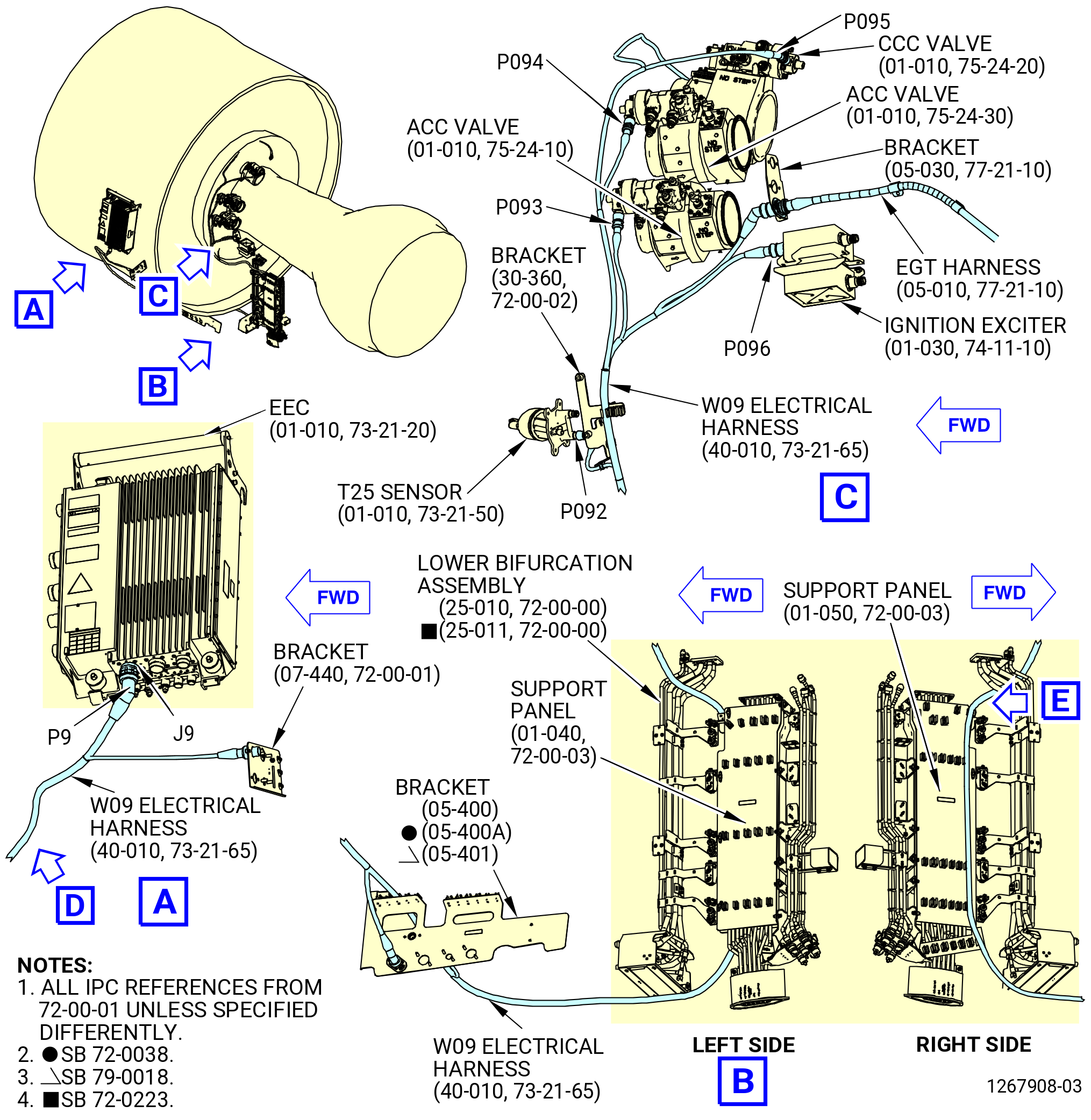
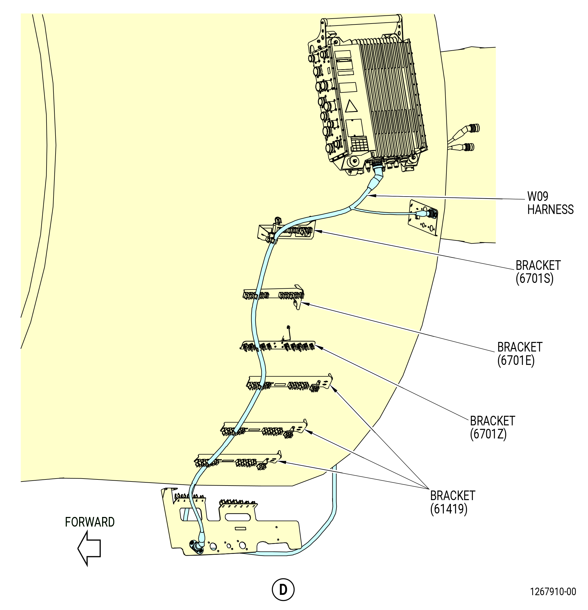
| L. | Remove the W09 electrical harness (harness) (67008) on the propulsor as follows. Refer to Figure 513. |
| (1) | Remove the W09 electrical harness from the spring clips on the brackets (30-360 , 72-00-02) (SIN 6711F), (05-300 , 72-00-01) (SIN 6701S), (05-330 , 72-00-01) (SIN 6701E), (07-470 , 72-00-01) (SIN 6701Z), (01-300 , 72-00-01) (SIN 61419), and (05-400 , 72-00-01) (SIN 6701F) or (05-401 , 72-00-01) (SIN 6701F). |
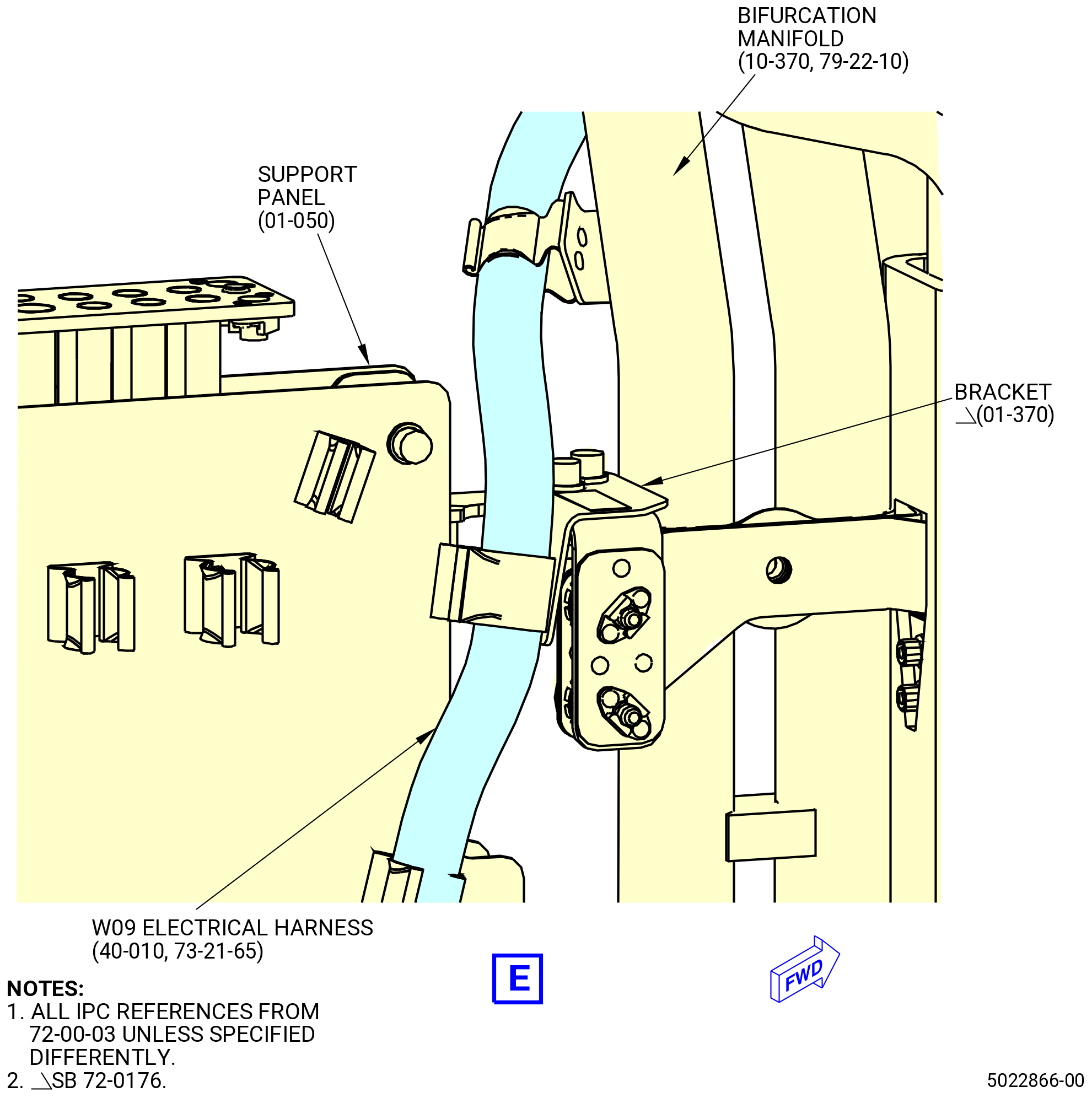
| (2) | Remove the W09 electrical harness from the spring clips on the support panel (01-050 , 72-00-03) (SIN 09711) on the right side, ALF, of the lower bifurcation assembly (25-010) (SIN 09400) or (25-011) (SIN 09400). |
| Subtask 72-00-00-030-327 |
| * * * SB 72-0176( Introduction of Additional Harness Support Bracket ) |
| (3) | Remove the W09 electrical harness from the spring clip on the harness support bracket (bracket) (01-370 , 72-00-03) (SIN 9901S). |
| NOTE: |
|
| * * * END SB 72-0176 |
| Subtask 72-00-00-030-328 |
| (4) | Remove the bolts and disconnect the W09 electrical harness receptacle (J0917) from the W01 electrical harness (67000) connector (P0117) at the bracket (6701L) below the EEC (65H00). |
| (5) | Loosen and disconnect the W09 electrical harness connector (P9) from the EEC receptacle (J9). |
| (6) | Remove the bolts and disconnect the W09 electrical harness connector (P0919) from the bracket (05-400 , 72-00-01) (SIN 6701F) or (05-401 , 72-00-01) (SIN 6701F). |
| (7) | Loosen and disconnect the W09 electrical harness connector (P092) from the T25 sensor (65200) receptacle. |
| (8) | Loosen and disconnect the W09 electrical harness connector (P096) from the ignition exciter (65800) No. 1 receptacle. |
| (9) | Remove the W09 electrical harness connector from the bracket (69810). |
| (10) | Loosen and disconnect the W09 electrical harness connector (P093, P094) from the active clearance control (ACC) valve (60500, 60600) receptacles. |
| (11) | Loosen and disconnect the W09 electrical harness connector (P095) from the core compartment cooling (CCC) valve (60300) receptacle. |
| (12) | Loosen and disconnect the W09 electrical harness connector (P097) from the EGT harness (69801) receptacle. |
| Subtask 72-00-00-030-379 |
| * * * PRE SB 75-0032( Two Separate Single-Channel Sensors ) |
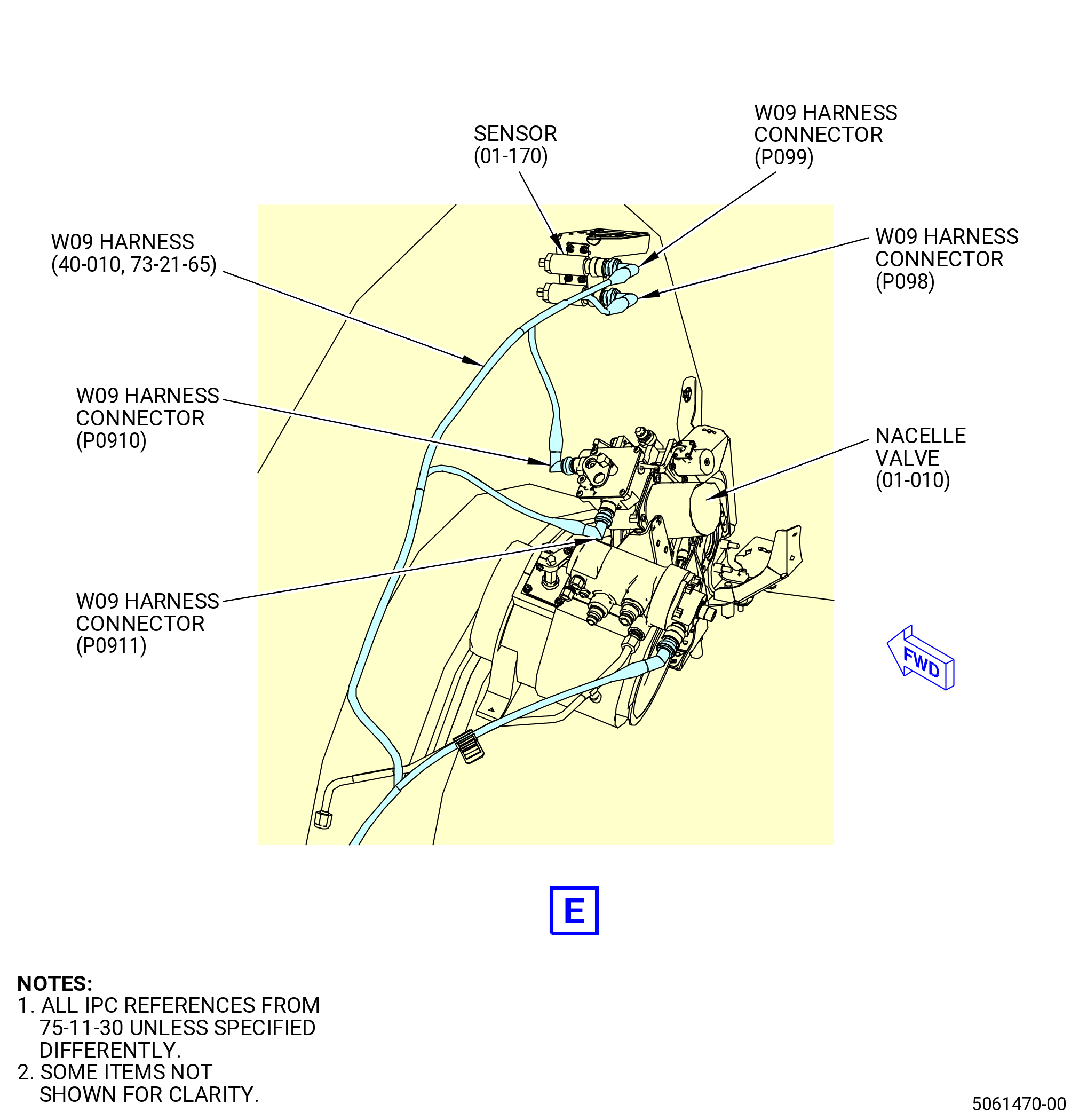
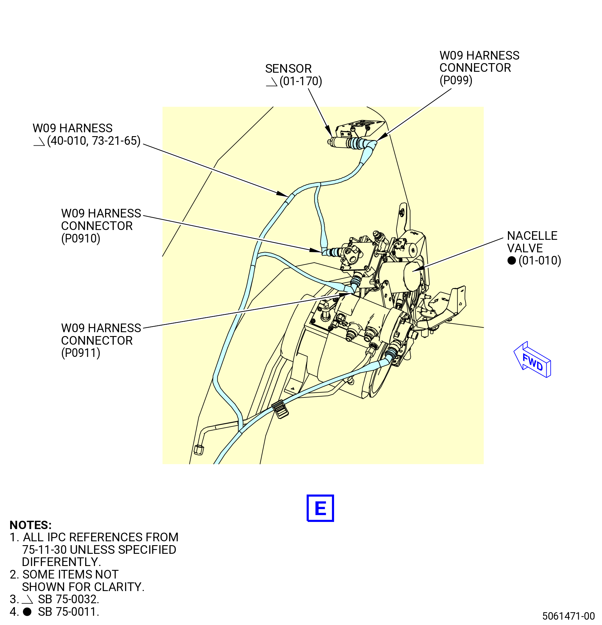
| (13) | Remove the W09 harness connectors (P098, P099) from the sensors (01-170 , 75-11-30) (SIN 63701) as follows: |
| (a) | Remove the W09 harness connector (P098) from the BAI PRESS-A port of the sensor. |
| (b) | Remove the W09 harness connector (P099) from the BAI PRESS-B port of the sensor. |
| * * * END PRE SB 75-0032 |
| Subtask 72-00-00-030-380 |
| * * * SB 75-0032( One Dual-Channel Sensor ) |
| (13).A. | Remove the W09 harness connector (P099) from the air pressure sensor (sensor) (01-170 , 75-11-30) (SIN 63701) as follows: |
| (a) | Remove the W09 harness connector (P099) from the BAI PRESS-B port of the sensor. |
| * * * END SB 75-0032 |
|
| Subtask 72-00-00-030-231 |
| CAUTION: |
|
| CAUTION: |
|
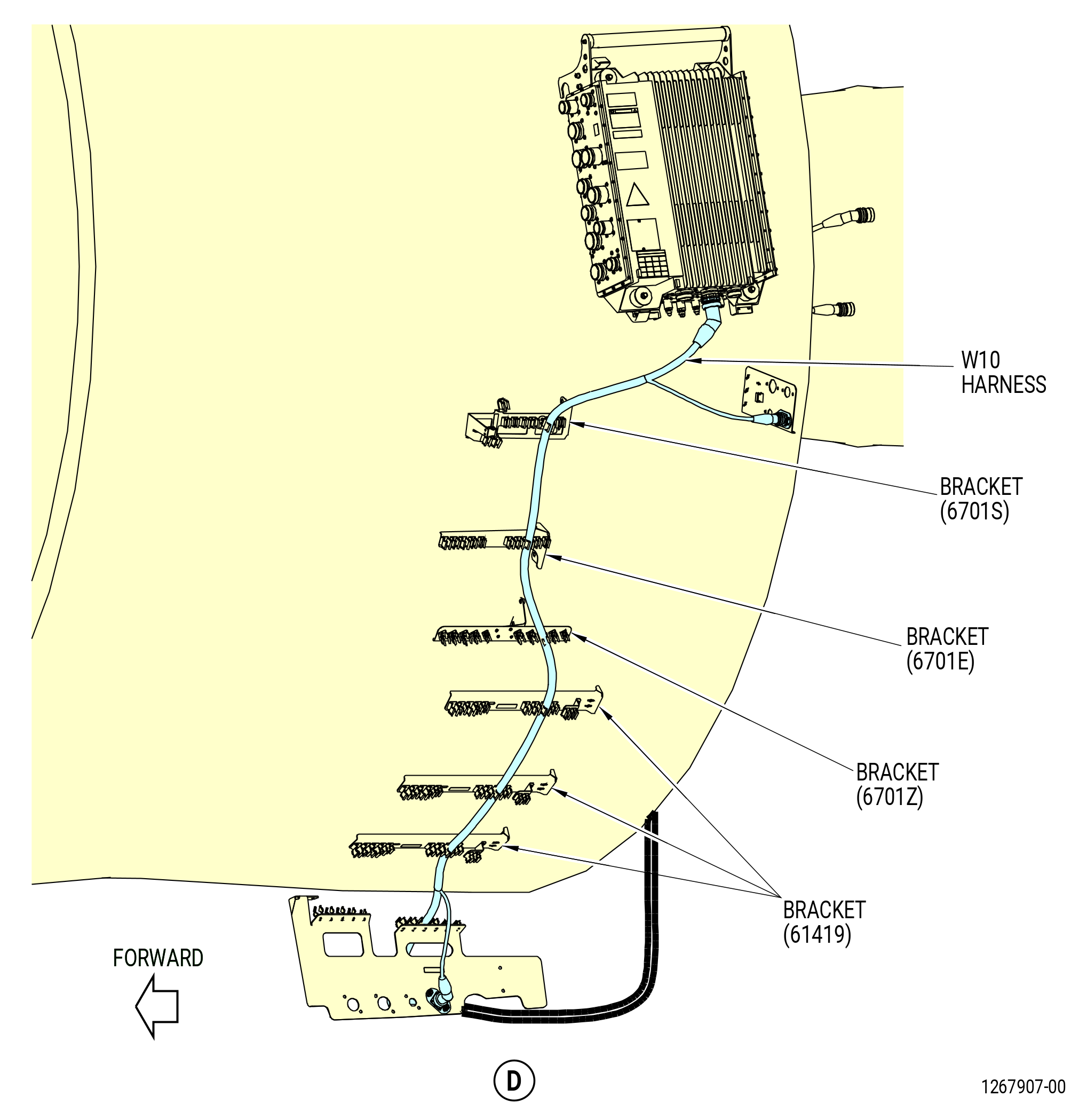
| M. | Remove the W10 electrical harness (harness) (67009) from the propulsor as follows. Refer to Figure 514. |
| (1) | Remove the W10 electrical harness from the spring clips on the brackets (30-360 , 72-00-02) (SIN 6711F), (05-300 , 72-00-01) (SIN 6701S), (05-330 , 72-00-01) (SIN 6701E), (07-470 , 72-00-01) (SIN 6701Z), (01-300 , 72-00-01) (SIN 61419), and (05-400 , 72-00-01) (SIN 6701F) or (05-401 , 72-00-01) (SIN 6701F). |
| (2) | Remove the W10 electrical harness from the spring clips identify with the PNK mark on the left side cable shield (support panel) (01-040 , 72-00-03) (SIN 09710) on the left side, ALF, of the lower bifurcation assembly (25-010) (SIN 09400) or (25-011) (SIN 09400). |
| (3) | Remove the W10 electrical harness from the spring clips on the bracket (25-270) (SIN 67115) on the left side, ALF, of the lower bifurcation assembly (25-010) (SIN 09400) or (25-011) (SIN 09400). |
| (4) | Remove the bolts and disconnect the W10 electrical harness receptacle (J1015) from the W02 electrical harness (67001) connector (P0215) at the bracket (6701L) below the EEC. |
| (5) | Loosen and disconnect the W10 electrical harness connector (P10) from the EEC (65H00) receptacle (J10). |
| (6) | Remove the bolts and disconnect the W10 electrical harness connector (P1021) from the bracket (05-400 , 72-00-01) (SIN 6701F) or (05-401 , 72-00-01) (SIN 6701F). |
| (7) | Loosen and disconnect the W10 electrical harness connector (P102) from the T25 sensor (65200) receptacle. |
| (8) | Loosen and disconnect the W10 electrical harness connector (P108) from the VBV actuator (30700) Channel B receptacle. |
| (9) | Loosen and disconnect the W10 electrical harness connector (P107) from the VSV actuator (30401) Channel B receptacle. |
| (10) | Loosen and disconnect the W10 electrical harness connector (P106) from the ignition exciter (65800) No. 2 receptacle. |
| (11) | Remove and disconnect the W10 electrical harness connector (P109) from the EGT harness (69802) receptacle at the bracket (69810). |
| (12) | Loosen and disconnect the W10 electrical harness connector (P103, P104) from the ACC valve (60500, 60600) receptacles. |
| (13) | Loosen and disconnect the W10 electrical harness connector (P105) from the CCC valve (60300) receptacle. |
| Subtask 72-00-00-030-232 |
| CAUTION: |
|
| CAUTION: |
|
| NOTE: |
|
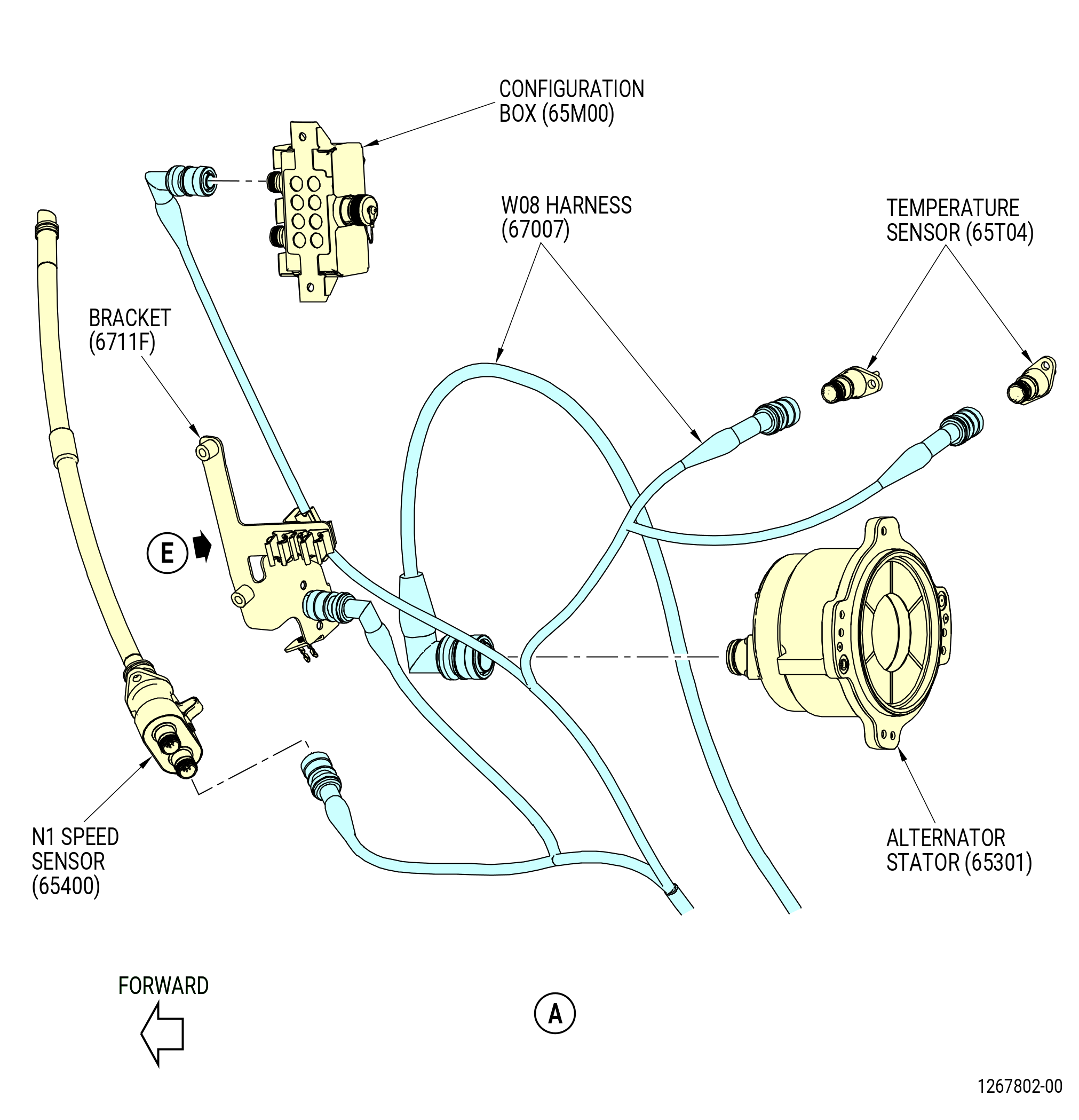
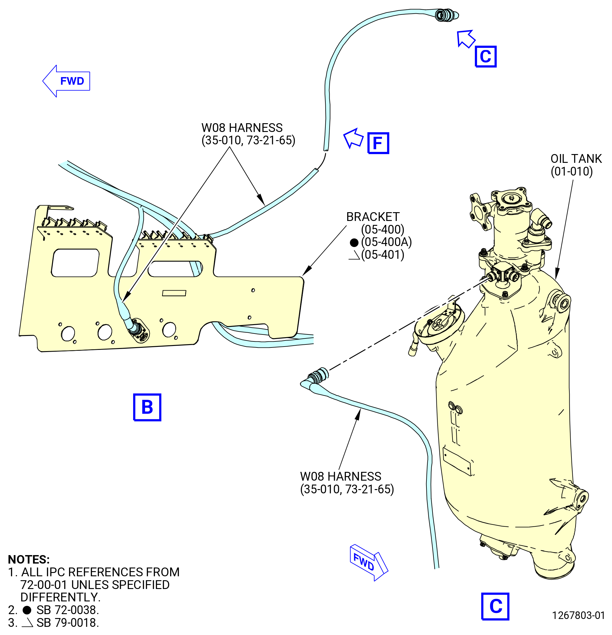
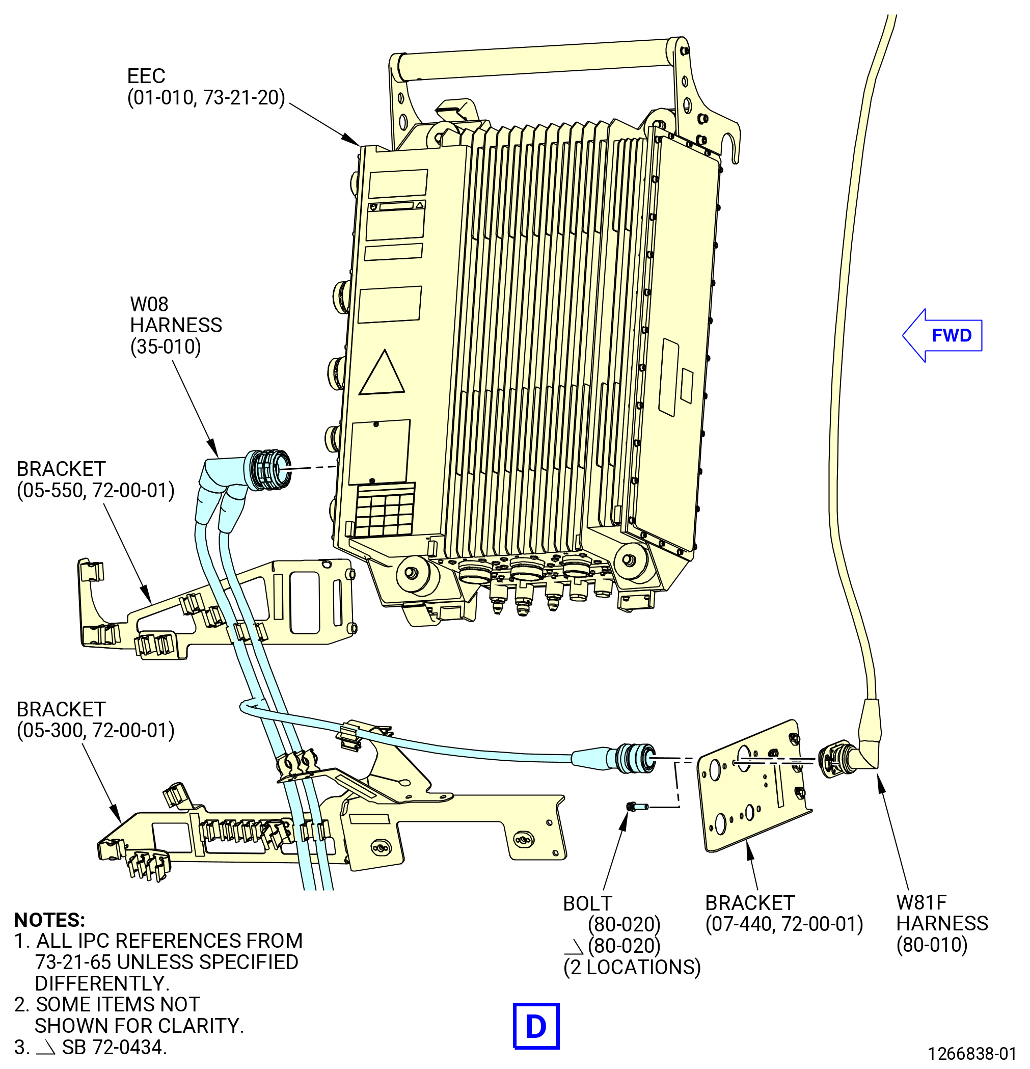
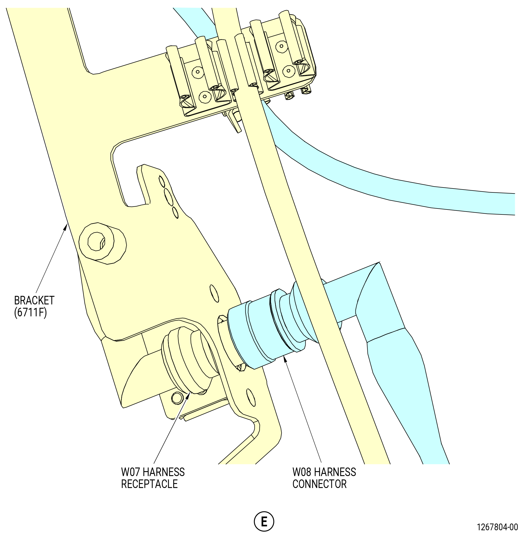
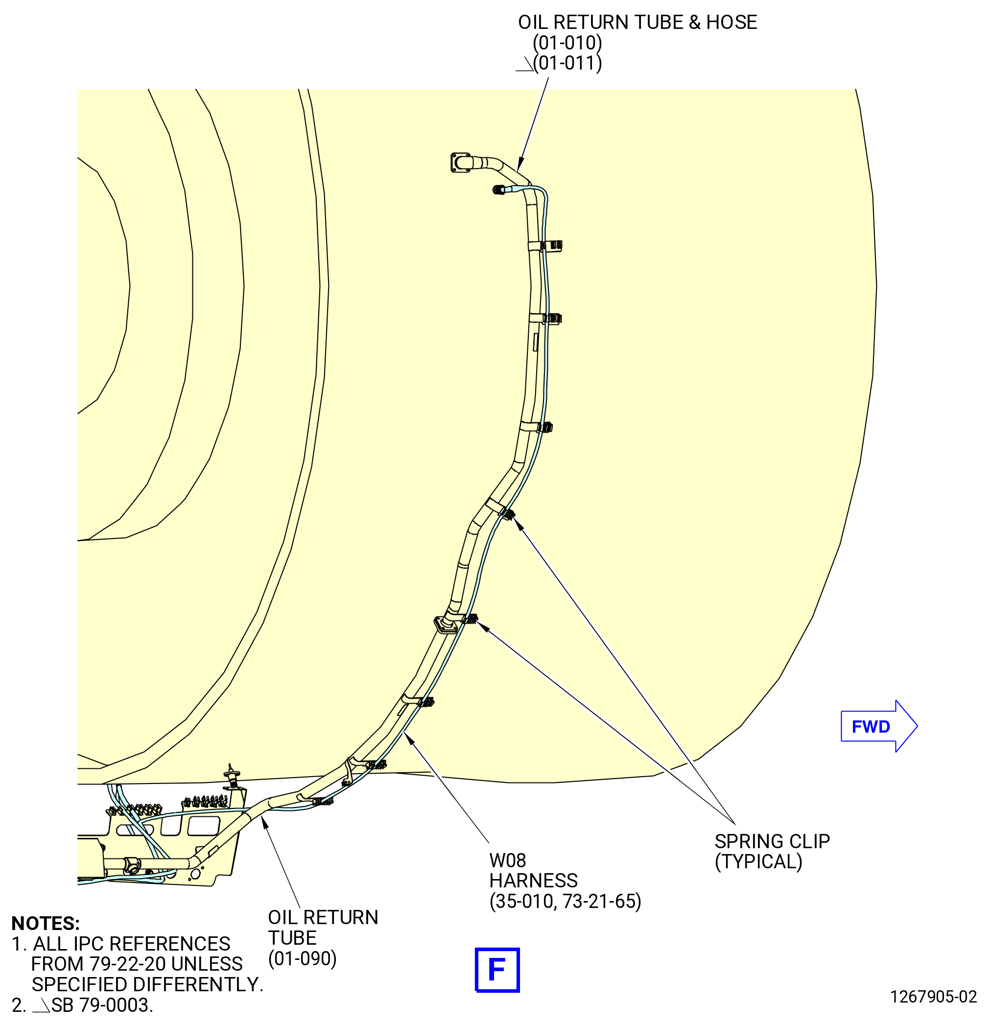
| N. | Remove the W08 electrical harness (harness) (67007) from the propulsor as follows. Refer to Figure 515. |
| (1) | Remove the W08 electrical harness from the spring clips on the brackets (30-360 , 72-00-02) (SIN 6711F), (05-300 , 72-00-01) (SIN 6701S), (05-330 , 72-00-01) (SIN 6701E), (07-470 , 72-00-01) (SIN 6701Z), (01-300 , 72-00-01) (SIN 61419), (01-510 , 72-00-05) (SIN 37110), and (01-210 , 72-00-05) (SIN 37111). |
| Subtask 72-00-00-030-419 |
| * * * PRE SB 73-0074( Harness Support Spring Clips with Clip Inserts ) |
| (2) | Remove the clip inserts (35-030 , 73-21-65) (SIN 67173) and (35-050 , 73-21-65) (SIN 67175) from bracket (01-510 , 72-00-05) (SIN 37110). |
| NOTE: |
|
| * * * END PRE SB 73-0074 |
| Subtask 72-00-00-030-420 |
| (3) | Remove the W08 electrical harness from the spring clips identify with the VIO mark on the support panel (01-040 , 72-00-03) (SIN 09710) on the left side, ALF, of the lower bifurcation assembly (25-010) (SIN 09400) or (25-011) (SIN 09400). |
| (4) | Remove the W08 electrical harness from the spring clips on the bracket (25-270) (SIN 67115) on the left side, ALF, of the lower bifurcation assembly (25-010) (SIN 09400) or (25-011) (SIN 09400). |
| (5) | Remove the W08 electrical harness from the spring clips on the oil return tube and hose (01-010 , 79-22-20) or (01-011 , 79-22-20) and oil return tube (01-090 , 79-22-20) (SIN 45302). |
| (6) | Remove the two machine bolts (bolts) (80-020 , 73-21-65) (SIN 67021) that attach the W81F harness connector (J082) to the bracket (07-440 , 72-00-01) (SIN 6701L). |
| (7) | Loosen and disconnect the W08 electrical harness connector (P8) from the EEC (65H00) receptacle (J8). |
| (8) | Loosen and disconnect the W08 electrical harness connector (P082) from the W81F electrical harness (6700G) receptacle (J082) at the bracket (6701L) below the EEC. |
| (9) | Loosen and disconnect the W08 electrical harness connector (P080) from the alternator stator (01-010 , 73-21-60) (SIN 65301) receptacle. |
| (10) | Loosen and disconnect the W08 electrical harness connector (P085) from the N1 speed sensor (65400) receptacle. |
| (11) | Loosen and disconnect the W08 electrical harness connectors (P086, P087) from the starter generator No. 1 and No. 2 outlet temperature sensors (temperature sensors) (65T04) receptacles. |
| (12) | Loosen and disconnect the W08 electrical harness connector (P0809) from the W07 harness (67006) receptacle (J0709) at the bracket (6711F). |
| (13) | Remove the bolts and W08 electrical harness connector (P0823) from the bracket (05-400 , 72-00-01) (SIN 6701F) or (05-401 , 72-00-01) (SIN 6701F). |
| (14) | Loosen and disconnect the W08 electrical harness connector (P084) from the configuration box (65M00) receptacle. |
| (15) | Loosen and disconnect the W08 electrical harness connector (P083) from the oil tank (01-010 , 72-00-01) (SIN 00400) receptacle. |
| Subtask 72-00-00-030-233 |
| CAUTION: |
|
| CAUTION: |
|
| NOTE: |
|
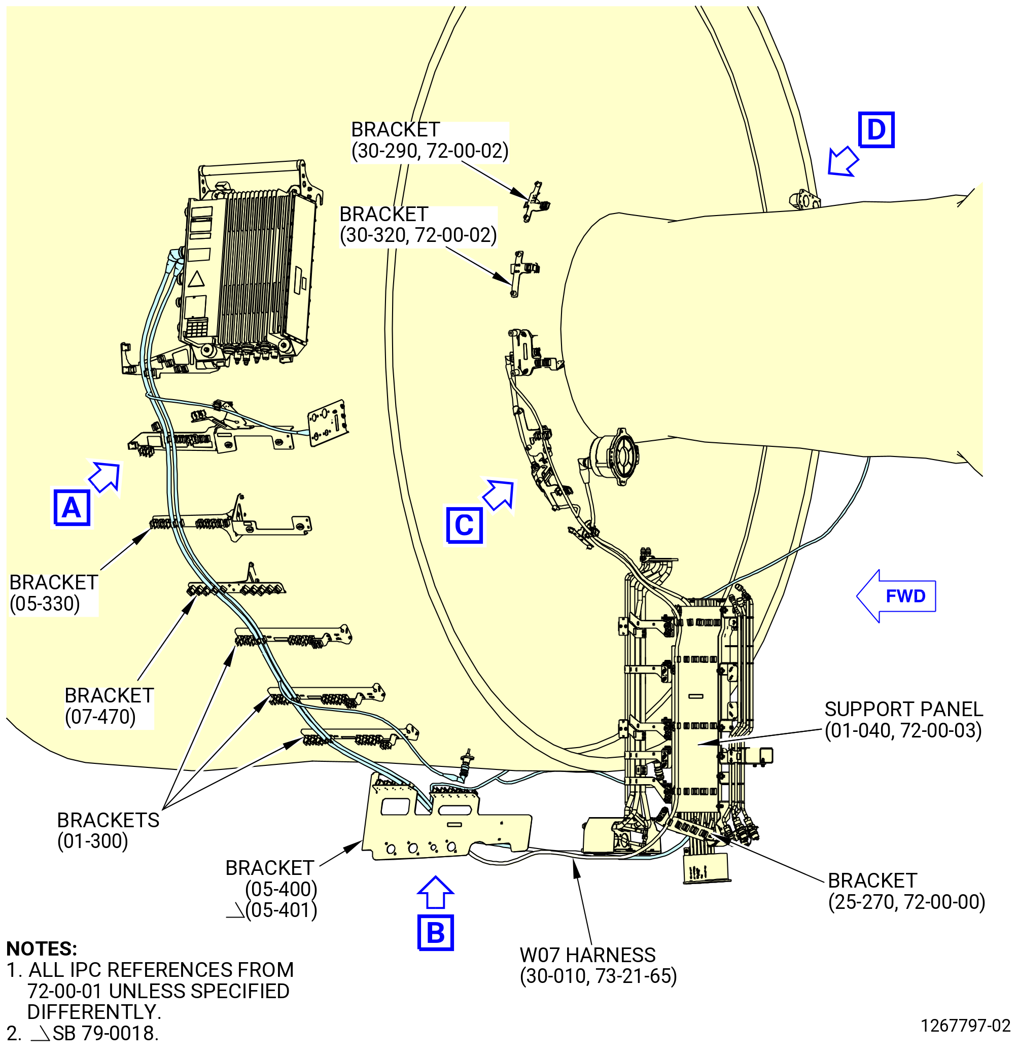
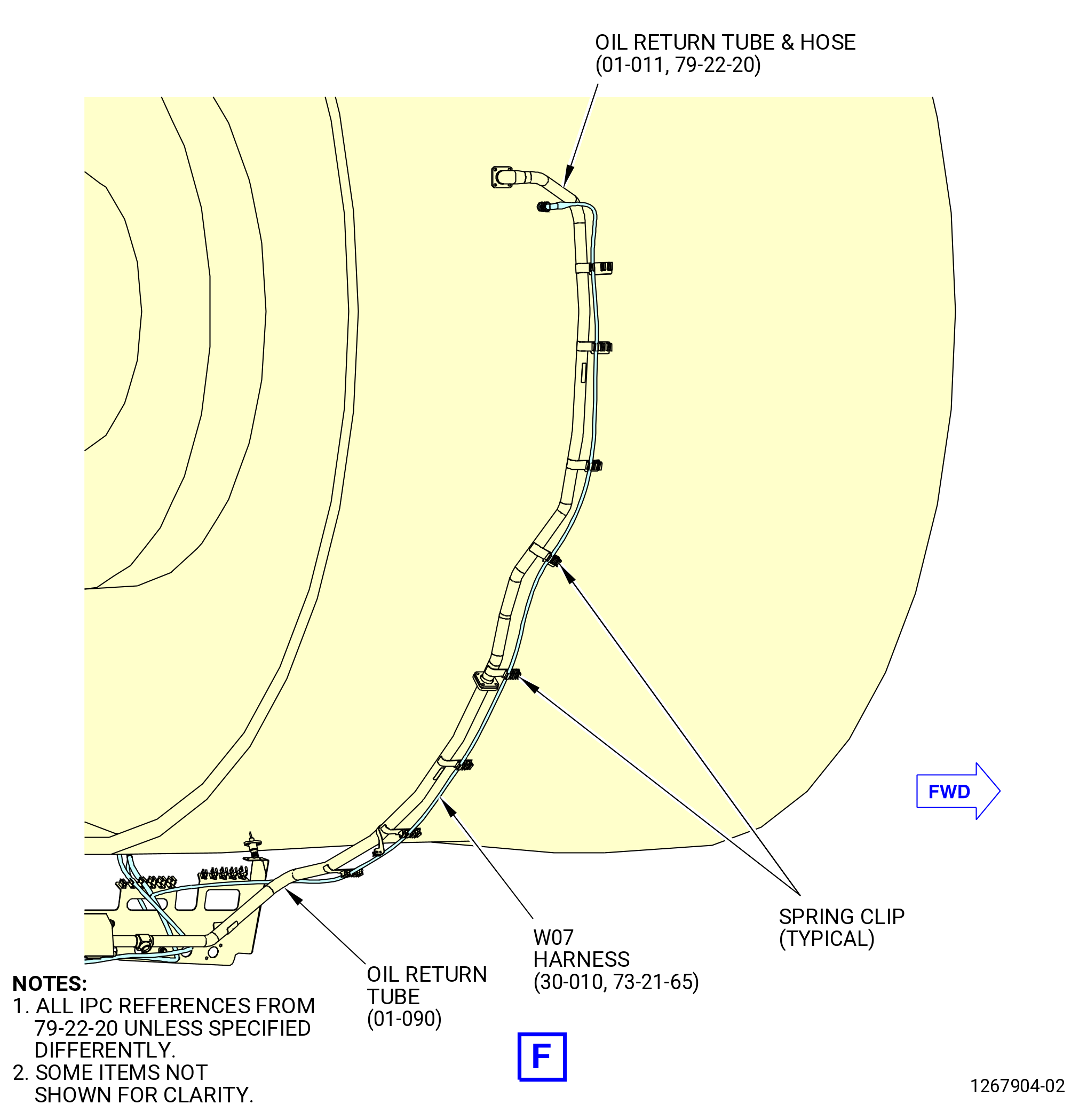
| O. | Remove the W07 electrical harness (harness) (67006) from the propulsor as follows. Refer to Figure 516. |
| (1) | Remove the W07 electrical harness from the spring clips on the brackets (30-430 , 72-00-02) (SIN 65M10), (30-360 , 72-00-02) (SIN 6711F), (10-410 , 79-22-10) (SIN 67217), (30-510 , 72-00-02) (SIN 67218), (30-320 , 72-00-02) (SIN 37710), (30-290 , 72-00-02) (SIN 37711), (30-490 , 72-00-02) (SIN 6721B), (05-550 , 72-00-01) (SIN 6701C), (05-300 , 72-00-01) (SIN 6701S), (05-330 , 72-00-01) (SIN 6701E), (07-470 , 72-00-01) (SIN 6701Z), (01-300 , 72-00-01) (SIN 61419), and (05-400 , 72-00-01) (SIN 6701F) or (05-401 , 72-00-01) (SIN 6701F). |
| (2) | Remove the W07 electrical harness from the spring clips on the support panel (01-040 , 72-00-03) (SIN 09710) on the left side, ALF, of the lower bifurcation assembly (25-010) (SIN 09400) or (25-011) (SIN 09400). |
| (3) | Remove the W07 electrical harness from the spring clips on the bracket (25-270) (SIN 67115) on the left side, ALF, of the lower bifurcation assembly (25-010) (SIN 09400) or (25-011) (SIN 09400). |
| (4) | Remove the W07 electrical harness from the spring clips identify with the BLU mark on the support panel (01-050 , 72-00-03) (SIN 09711) on the right side, ALF, of the lower bifurcation assembly (25-010) (SIN 09400) or (25-011) (SIN 09400). |
| (5) | Remove the W07 electrical harness from the spring clips on the bracket (25-300) (SIN 67116) on the right side, ALF, of the lower bifurcation assembly (25-010) (SIN 09400) or (25-011) (SIN 09400). |
| (6) | Remove the W07 electrical harness from the spring clips on the oil return tube and hose (01-010 , 79-22-20) or (01-011 , 79-22-20) and oil return tube (01-090 , 79-22-20) (SIN 45302). |
| (7) | Loosen and disconnect the W07 electrical harness connector (P7) and harness from the EEC (65H00) receptacle (J7). |
| (8) | Remove the machine bolts (bolts) (70-020 , 73-21-65) (SIN 67021) that attach the W71F harness connector (J072) to the bracket (07-440 , 72-00-01) (SIN 6701L). |
| (9) | Loosen and disconnect the W07 electrical harness connector (P072) from the W71F harness (6700F) receptacle (J072) at the bracket (6701L) below the EEC. |
| (10) | Loosen and disconnect the W07 electrical harness connectors (P074, P075) from the starter generator No. 1 and No. 2 inlet temperature sensors (temp sensors) (65T03) receptacles. |
| (11) | Remove the bolts and W07 electrical harness receptacle (J0709) from the bracket (6711F). |
| (12) | Loosen and disconnect the W07 electrical harness connector (P078) from the N1 speed sensor (65400) receptacle. |
| (13) | Loosen and disconnect the W07 electrical harness connector (P077) from the configuration box (65M00) receptacle. |
| (14) | Loosen and disconnect the W07 electrical harness connector (P070) from the alternator stator (01-010 , 73-21-60) (SIN 65301) receptacle. |
| (15) | Deleted. |
| (16) | Loosen and disconnect the W07 electrical harness connector (P073) from the temperature sensor (01-020 , 79-31-40) (SIN 400A3). |
| Subtask 72-00-00-030-234 |
| CAUTION: |
|
| CAUTION: |
|
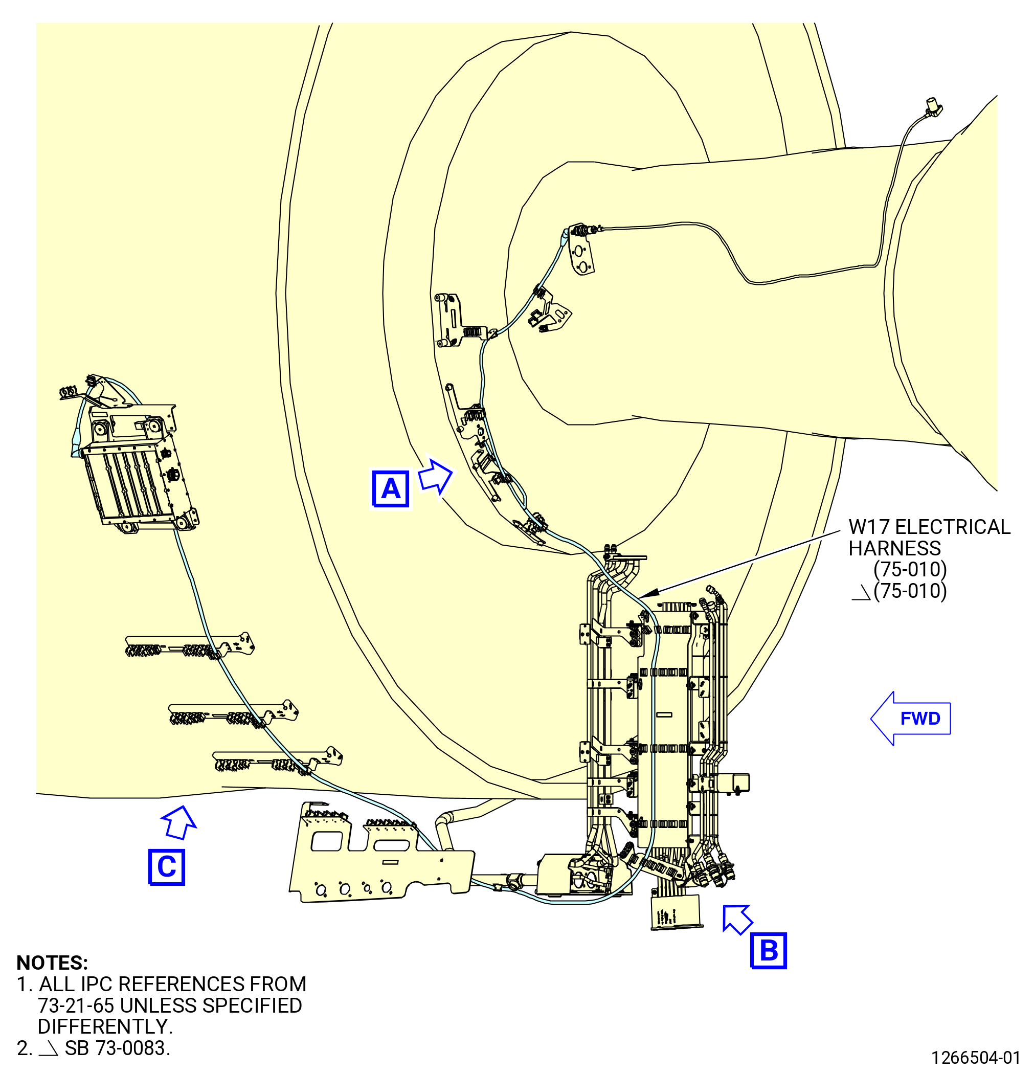
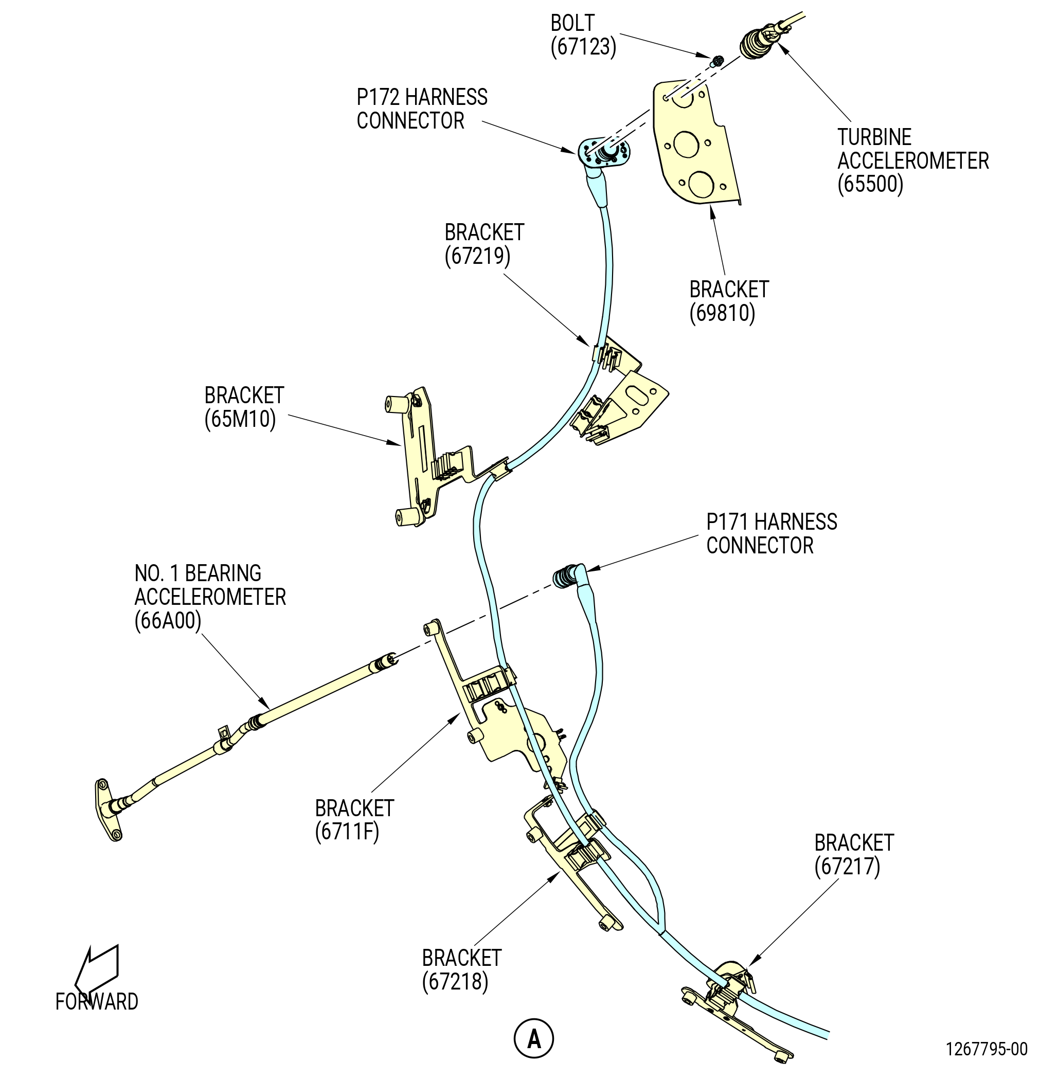
| P. | Remove the W17 electrical harness (75-010 , 73-21-65) (SIN 6710B) from the propulsor. Refer to Figure 517 and do as follows: |
| (1) | Remove the harness from the spring clips on the brackets (65M10, 6711F, 67217, 67218, 67219). |
| (2) | Remove the W17 electrical harness from the spring clips on the support panel (01-040 , 72-00-03) (SIN 09710) on the left side, ALF, of the lower bifurcation assembly (25-010) (SIN 09400) or (25-011) (SIN 09400). |
| (3) | Remove the W17 electrical harness from the spring clips on the bracket (25-270) (SIN 67115) on the left side, ALF, of the lower bifurcation assembly (25-010) (SIN 09400) or (25-011) (SIN 09400). |
| (4) | Remove the W17 electrical harness from the spring clips on the brackets (01-300 , 72-00-01) (SIN 61419), (05-400 , 72-00-01) (SIN 6701F) or (05-401 , 72-00-01) (SIN 6701F), and (05-210 , 72-00-01) (SIN 6701U). |
| (5) | Remove the W17 electrical harness from the spring clips on the tube (44000). |
| (6) | Remove the bolts (67123) and W17 electrical harness connector (P172) from the turbine accelerometer (65500) receptacle at the bracket (69810). |
| (7) | Remove the W17 electrical harness connector (P171) from the No. 1 bearing accelerometer (66A00) receptacle. |
| (8) | Loosen and disconnect the W17 electrical harness connector (P17) from the EMU (65Z00) receptacle. |
| Subtask 72-00-00-030-235 |
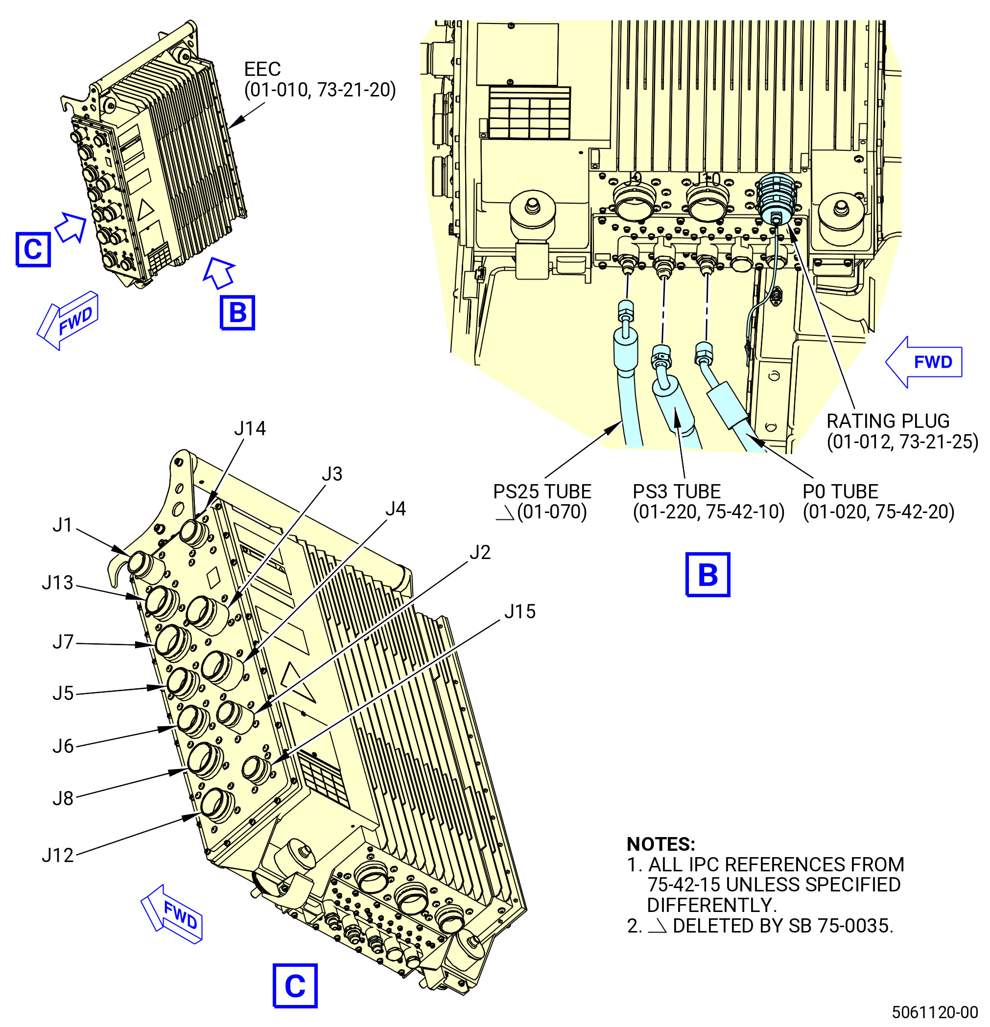
| Q. | Remove the rating plug, full authority digital engine control (FADEC) cables, and air system tubes from the EEC and EMU as follows. Refer to Figure 518. |
| (1) | Remove the rating plug as follows: |
| (a) | Loosen the bolt on the aft fan case flange that holds the rating plug lanyard at the top right port on the bottom of the EEC. |
| (b) | Remove the rating plug. |
| (2) | Remove the FADEC cables (J1 thru J10 J12 thru J15, and J17 thru J21) from the EEC and EMU as follows: |
| (a) | Loosen the knurled couplings on the cable connectors that attach to the EEC and EMU. |
| (b) | Remove the FADEC cables from the EEC and EMU. |
| Subtask 72-00-00-030-381 |
| * * * PRE SB 75-0035( Engines with PS35 Pressure Sense Tube and Air P25 Hose Tube ) |
| (3) | Remove the three air system tubes (P0, PS3, and PS25) from the EEC as follows: |
| * * * END PRE SB 75-0035 |
| Subtask 72-00-00-030-382 |
| * * * SB 75-0035( Engines Without P25 Pressure Sense Tube and Air P25 Hose Tube ) |
| (3).A. | Remove the two air system tubes (P0 and PS3) from the EEC as follows: |
| * * * END SB 75-0035 |
| Subtask 72-00-00-030-383 |
| (a) | Loosen the B-nuts of the tubes. |
| (b) | Remove the tubes from the EEC ports. |
| Subtask 72-00-00-440-085 |
| * * * SB 79-0018( MFOHX with Indicating Capability ) |
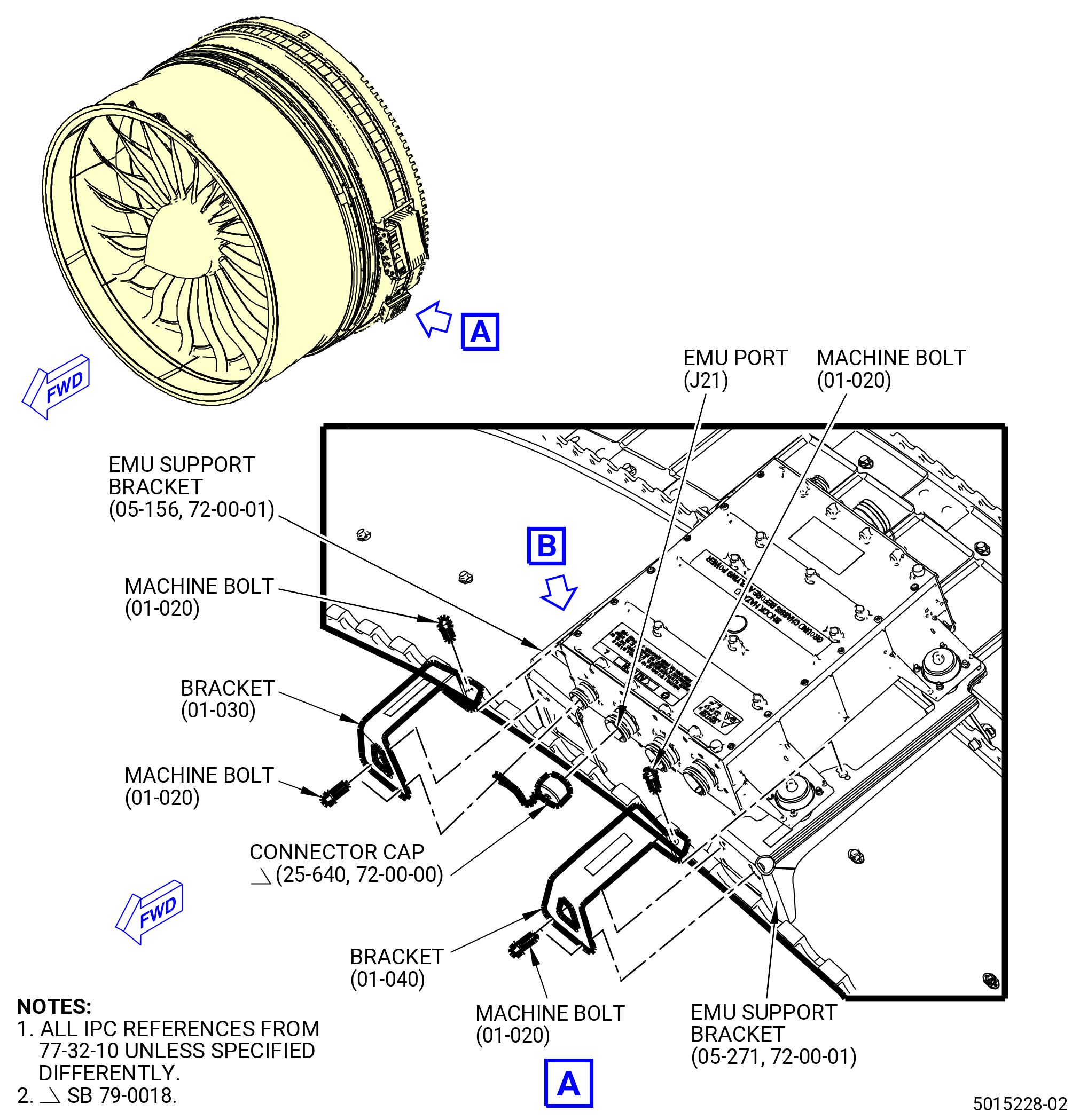
| (4) | Remove the connector cap (25-640) (SIN 65K02). Refer to Figure 519 and do as follows: |
| NOTE: |
|
| (a) | Disconnect the connector cap from the EMU port (J21). |
| (b) | Loosen and remove the machine bolt (01-020 , 77-32-10) (SIN 65Z20) on the bracket (01-030 , 77-32-10) (SIN 65Z15) that holds the lanyard of the connector cap. |
| (c) | Remove the connector cap. |
| * * * END SB 79-0018 |
| Subtask 72-00-00-030-294 |
| CAUTION: |
|
| R. | Remove the EEC and EMU as follows. Refer to Figure 518. |
| Subtask 72-00-00-030-295 |
| * * * SB 72-0056( New EMU Brackets ) |
| (1) | Loosen and remove the machine bolts (01-020 , 77-32-10) (SIN 65Z20) that attach the brackets (01-030 , 77-32-10) (SIN 65Z15) and (01-040 , 77-32-10) (SIN 65Z16) to the EMU support brackets (05-271 , 72-00-01) (SIN 65Z10) and (05-156 , 72-00-01) (SIN 65Z12)located at the 4:00 o'clock position, forward looking aft (FLA), on the aft fan case. Refer to Figure 519. |
| (2) | Remove the brackets (01-030 , 77-32-10, 01-040 , 77-32-10). |
| NOTE: |
|
| * * * END SB 72-0056( ) |
| Subtask 72-00-00-030-236 |
| (3) | Remove the EEC (65H00) from the fan case as follows. Refer to Figure 520. |
| (a) | Attach the 11C4649 EEC lift fixture to the EEC with the two ball-lock pins (item 6) at the EEC handle. |
| (b) | Attach the base assembly to the 9446M93 jack stand. |
| (c) | Move the 9446M93 jack stand and attached base assembly into position next to the EEC and 11C4649 EEC lift fixture. |
| (d) | Turn the adjustment knobs to angle the base assembly to the correct position. |
| (e) | Slowly adjust the base assembly and the 9446M93 jack stand until the base assembly is aligned with the 11C4649 EEC lift fixture. |
| (f) | Make sure that the pin (item 9) on the 11C4649 EEC lift fixture is in the correct position on the base assembly. |
| (g) | Attach the base assembly to the 11C4649 EEC lift fixture with the pin (item 9). |
| (h) | Loosen the four captive bolts that attach the EEC to the fan case mount brackets. |
| NOTE: |
|
| NOTE: |
|
| (i) | Carefully move the EEC away from the aft fan case brackets with the 9446M93 jack stand. |
| CAUTION: |
|
| (j) | Remove the EEC from the 11C4649 EEC lift fixture as follows: |
| 1 | Attach a suitable hoist to the 11C4649 EEC lift fixture. |
| NOTE: |
|
| 2 | Lift the 11C4649 EEC lift fixture with the attached EEC, so the hoist supports the weight of the EEC. |
| 3 | Remove the pin (item 9) that holds the 11C4649 EEC lift fixture to the base assembly. |
| 4 | Lift the 11C4649 EEC lift fixture and the attached EEC from the base assembly. |
| 5 | Put the EEC and 11C4649 EEC lift fixture down. |
| NOTE: |
|
| 6 | Remove the two ball-lock pins (item 6) that hold the EEC to the 11C4649 EEC lift fixture. |
| 7 | Remove the EEC from the 11C4649 EEC lift fixture. |
| (4) | Loosen and remove the four captive bolts and EEC from the FADEC support brackets at the 3:00 o'clock location FLA on the aft fan case. |
| Subtask 72-00-00-030-423 |
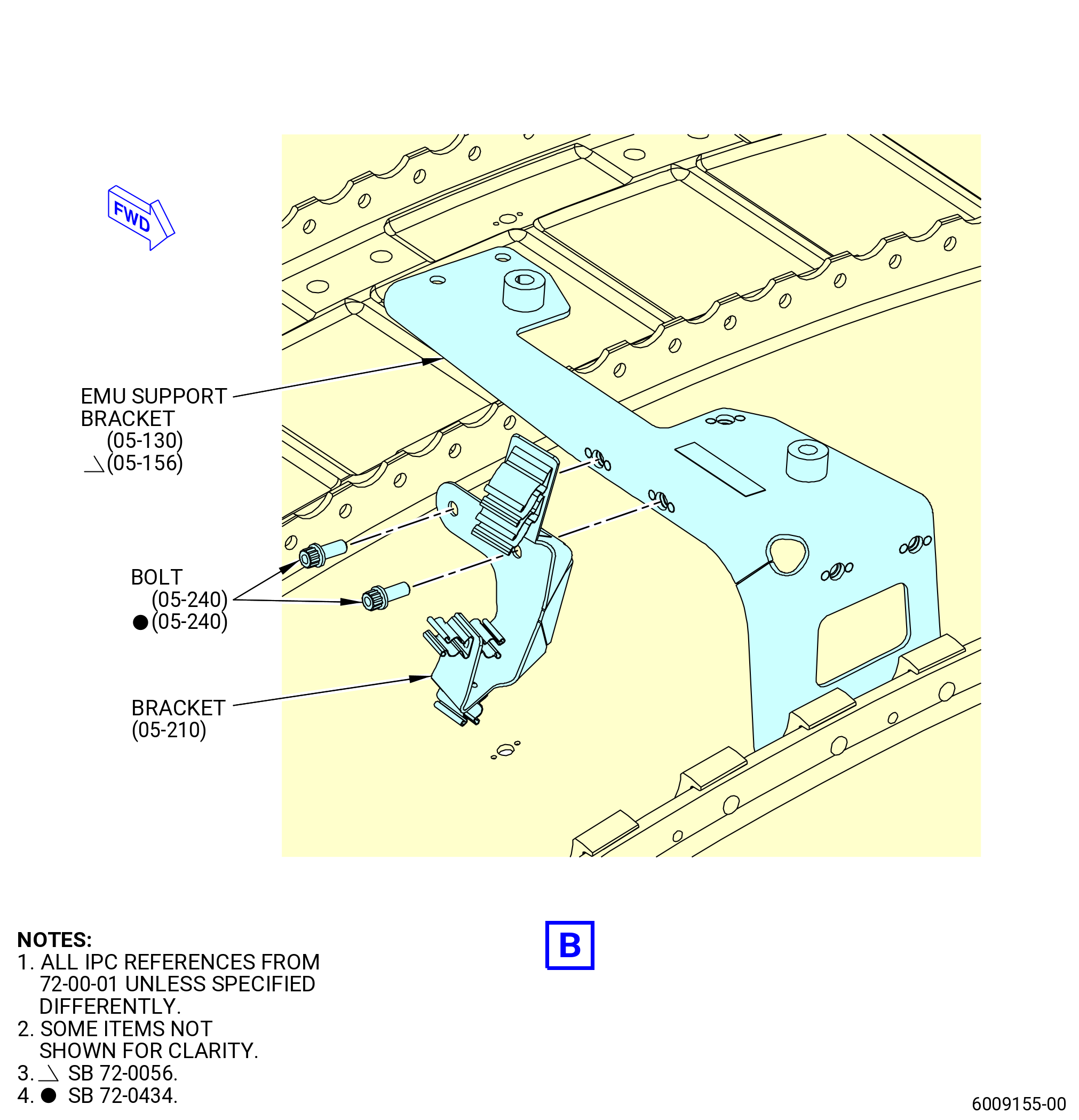
| (5) | Remove the support bracket (bracket) (05-210 , 72-00-01) (SIN 6701U) as follows: |
| (a) | Remove the two machine bolts (bolts) (05-240 , 72-00-01) (SIN 67021) that attach the bracket (05-210 , 72-00-01) (SIN 6701U) to the EMU support bracket (05-130 , 72-00-01) (SIN 65Z12) or (05-156 , 72-00-01) (SIN 65Z12). |
| (b) | Remove the bracket (05-210 , 72-00-01) (SIN 6701U) from the EMU support bracket (05-130 , 72-00-01) (SIN 65Z12) or (05-156 , 72-00-01) (SIN 65Z12). |
|
| Subtask 72-00-00-030-238 |
| S. | Remove the T12 sensor kit (738L104). Refer to TASK 71-00-00-020-806 (71-00-00, REMOVAL 001). |
| Subtask 72-00-00-030-239 |
| T. | Remove the fan module - fan bracket (738L102) as follows. Refer to TASK 72-00-01-040-805 (72-00-01, DISASSEMBLY 001). |
| Subtask 72-00-00-030-240 |
| U. | Remove the VFSG (7002879/7001330). Refer to TASK 72-00-02-030-801 (72-00-02, DISASSEMBLY 001). |
| Subtask 72-00-00-030-241 |
| V. | Remove the fire detector. Refer to TASK 72-00-02-030-802 (72-00-02, DISASSEMBLY 002 - CONFIG 01) or TASK 72-00-02-030-808 (72-00-02, DISASSEMBLY 002 - CONFIG 02). |
| Subtask 72-00-00-030-242 |
| W. | Remove the engine anti-ice as follows. Refer to TASK 72-00-02-030-802 (72-00-02, DISASSEMBLY 002 - CONFIG 01) or TASK 72-00-02-030-808 (72-00-02, DISASSEMBLY 002 - CONFIG 02). |
| Subtask 72-00-00-030-243 |
| X. | Remove the lower bifurcation assembly. Refer to TASK 72-00-03-020-802 (72-00-03, REMOVAL 001). |
| Subtask 72-00-00-030-244 |
| Y. | Remove the fan stator module assembly (fan stator module). Refer to TASK 72-00-01-020-801 (72-00-01, REMOVAL 001). |
| Subtask 72-00-00-030-245 |
| Z. | Disassemble the engine propulsor. Refer to TASK 72-00-02-030-801 (72-00-02, DISASSEMBLY 001). |