| GENX-1B ENGINE MANUAL | Dated: 02/20/2020 | |
| EM 72-00-03 , REMOVAL 001 | ||
| LOWER BIFURCATION ASSEMBLY - REMOVAL 001 | ||
| GENX-1B ENGINE MANUAL | Dated: 02/20/2020 | |
| EM 72-00-03 , REMOVAL 001 | ||
| LOWER BIFURCATION ASSEMBLY - REMOVAL 001 | ||
| * * * FOR ALL |
| TASK 72-00-03-020-802 |
| 1 . | General. |
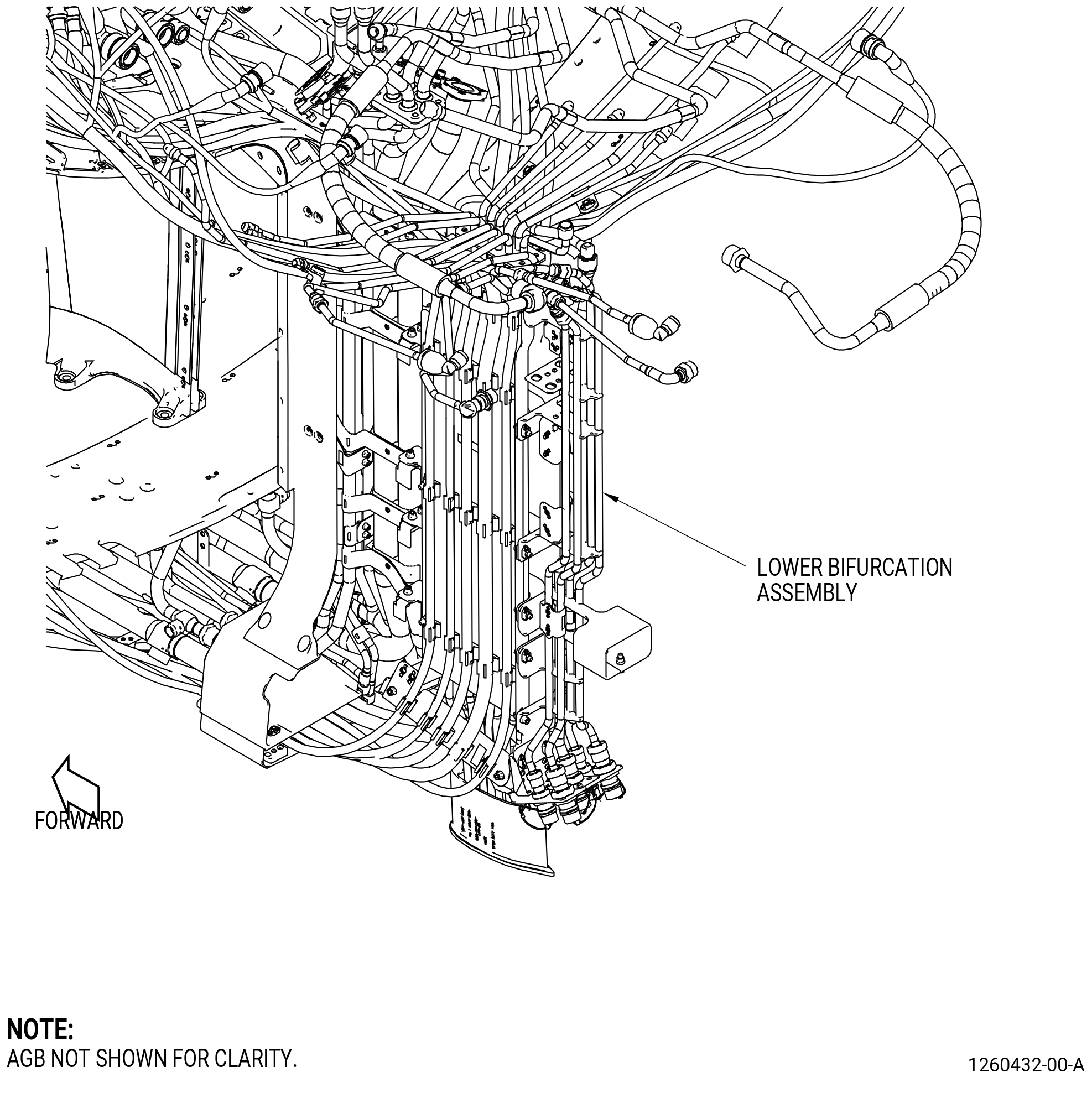
| A. | This procedure gives instructions to remove the lower bifurcation assembly (25-010 , 72-00-00) (SIN 09400) or (25-011 , 72-00-00) (SIN 09400) from the aft fan stator case assembly (01-020 , 72-00-01) (SIN 00109) or (01-021 , 72-00-01) (SIN 00109). Refer to Figure 302. |
| B. | This procedure starts with the assembled engine in the horizontal position installed in the 11C4487 shipping stand with the fan stator module assembly attached to the 11C4490 separation dolly, or the 11C3044 engine module adapter assembly attached to the customer overhead rail system, or in the 11C3281 pedestals at the equivalent disassembly status of TASK 72-00-00-030-801 (72-00-00, DISASSEMBLY 001) . |
| 2 . | Tools, Equipment, and Materials. |
| NOTE: |
|
| A. | Tools and Equipment. |
| (1) | Special Tools. |
| (2) | Standard Tools and Equipment. None. |
| (3) | Locally Manufactured Tools. None. |
| B. | Consumable Materials. None. |
| C. | Referenced Procedures. Refer to Engine Manual GEK 112851. |
|
| D. | Expendable Parts. None. |
| 3 . | Procedure. |
| Subtask 72-00-03-020-029 |
| A. | Deleted. |
| Subtask 72-00-03-020-030 |
| A.A. | Deleted. |
| Subtask 72-00-03-020-011 |
| B. | Drain the oil tank before you disconnect the oil tubes. |
| Subtask 72-00-03-020-021 |
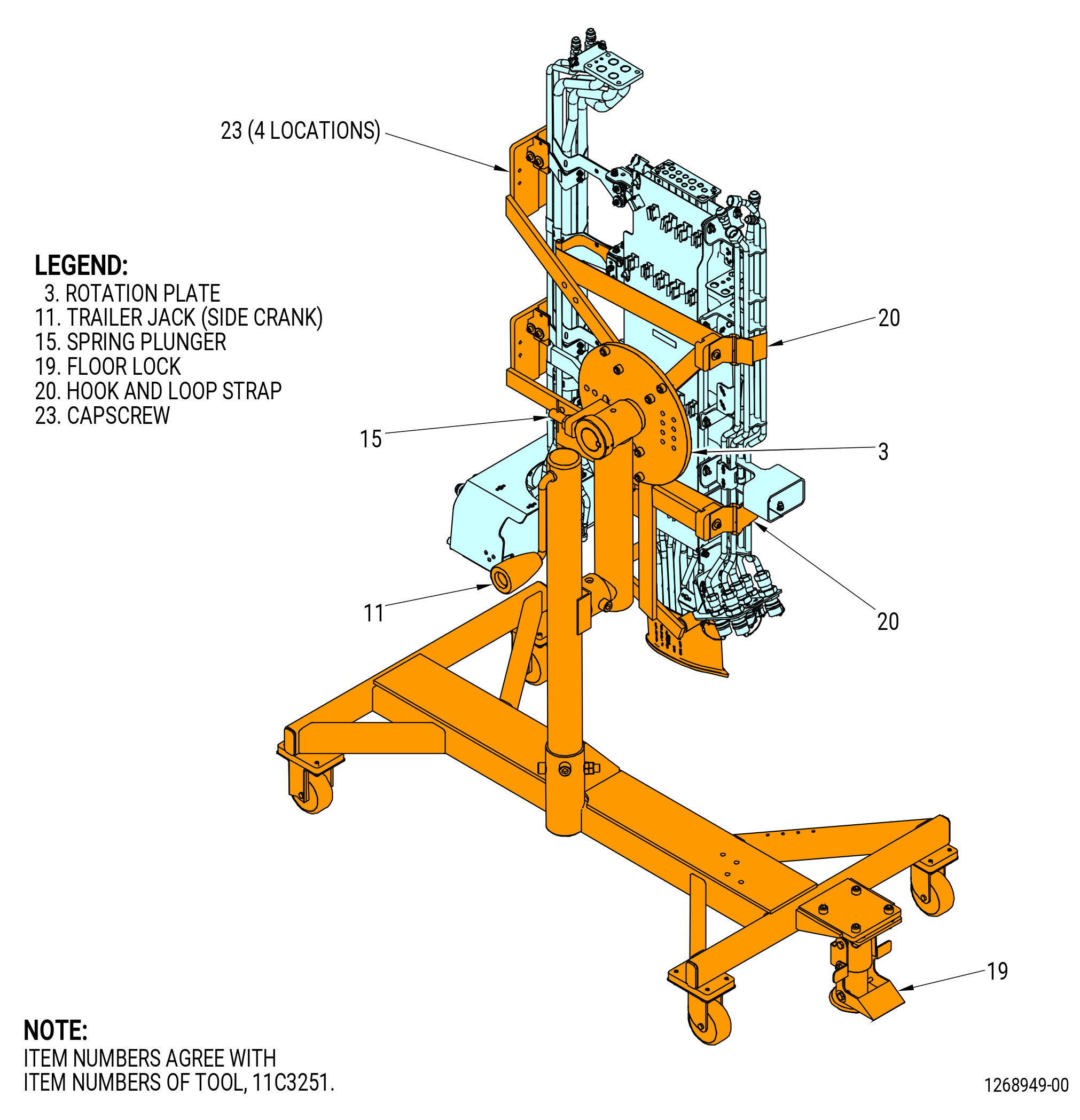
| C. | Install the 11C3251 installation fixture to the lower bifurcation assembly as follows. Refer to Figure 302 and Figure 303. |
| (1) | Make sure that the rotation plate (item 3) is in the vertical position. If necessary, turn the rotation plate (item 3) as follows: |
| (a) | Pull on the spring plunger (item 15) and slowly turn the rotation plate (item 3) to the vertical position. |
| (b) | Re-insert the spring plunger (item 15) and lock the rotation plate (item 3). |
| (2) | Put the 11C3251 installation fixture next to the lower bifurcation assembly as follows: |
| (a) | Adjust the height of the 11C3251 installation fixture with the side crank of the trailer jack (item 11). |
| (b) | Put the arms around the lower bifurcation assembly. |
| CAUTION: |
|
| (c) | Put the floor lock (item 19) in the locked (down) position. Make sure the floor lock contacts the floor. |
| (3) | Attach the lower bifurcation assembly to the 11C3251 installation fixture as follows: |
| (a) | Attach the brackets with the capscrews (item 23) at four locations. |
| (b) | Attach the hook and loop strap (item 20) around the lower bifurcation assembly and secure at two locations. Do not apply too much force with the hook and loop strap. |
| Subtask 72-00-03-020-012 |
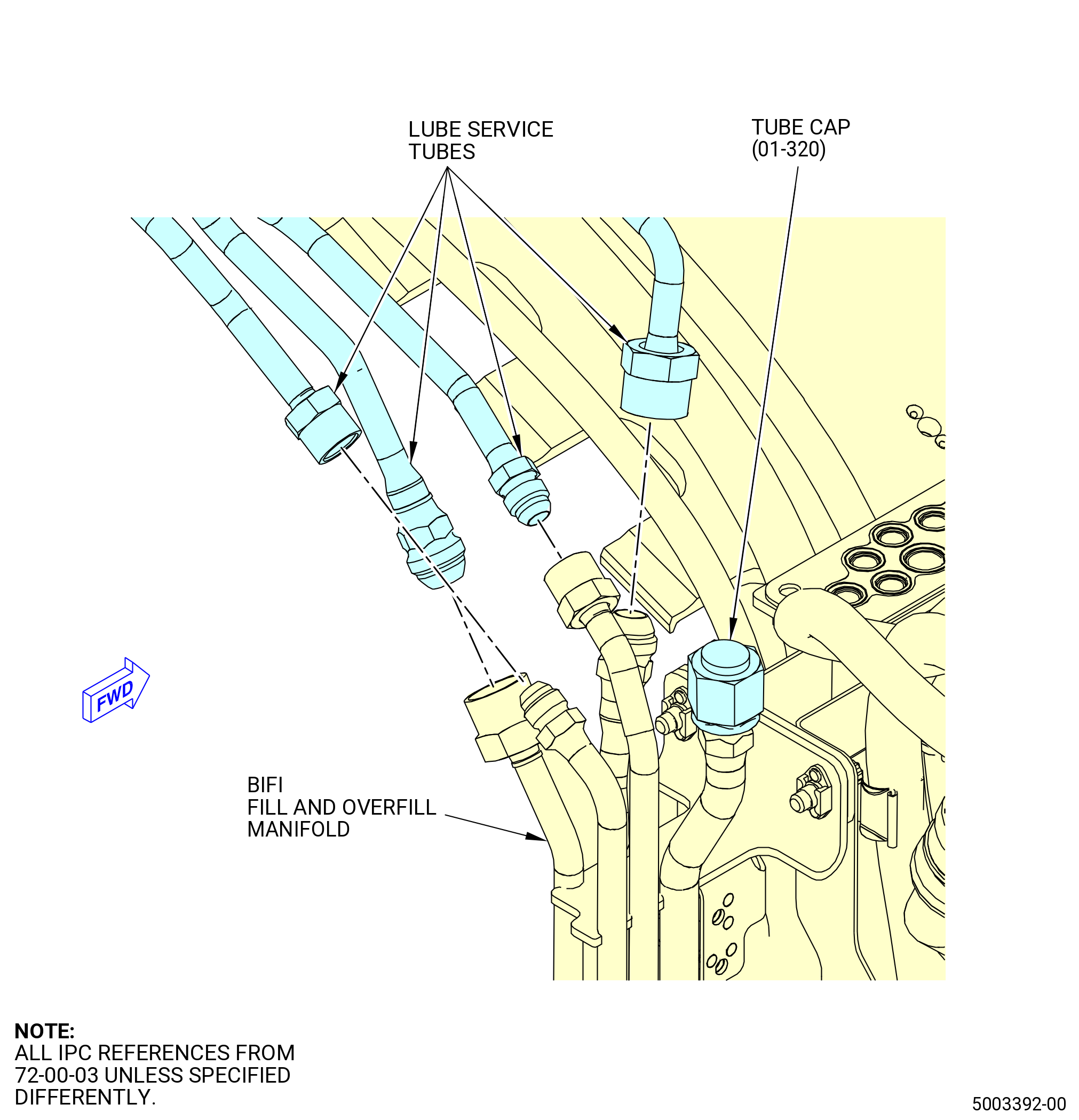
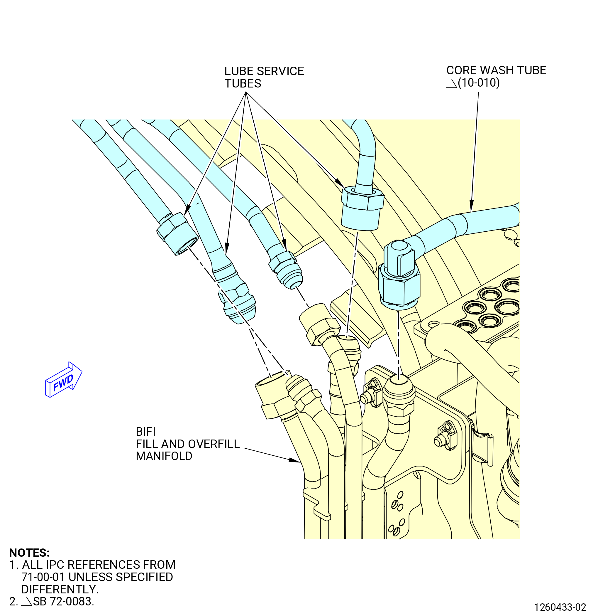
| D. | Disconnect the lube service tubes and core wash tube (10-010 , 71-00-01) (SIN 78001) from the aft top side of the lower bifurcation assembly as follows. Refer to Figure 304. |
| (1) | Disconnect the B-nuts of the four lube service tubes and the core wash tube (10-010 , 71-00-01) (SIN 78001) if installed, at the bifurcation (BIFI) fill and overfill manifold on the aft side of the lower bifurcation assembly. |
| Subtask 72-00-03-020-013 |
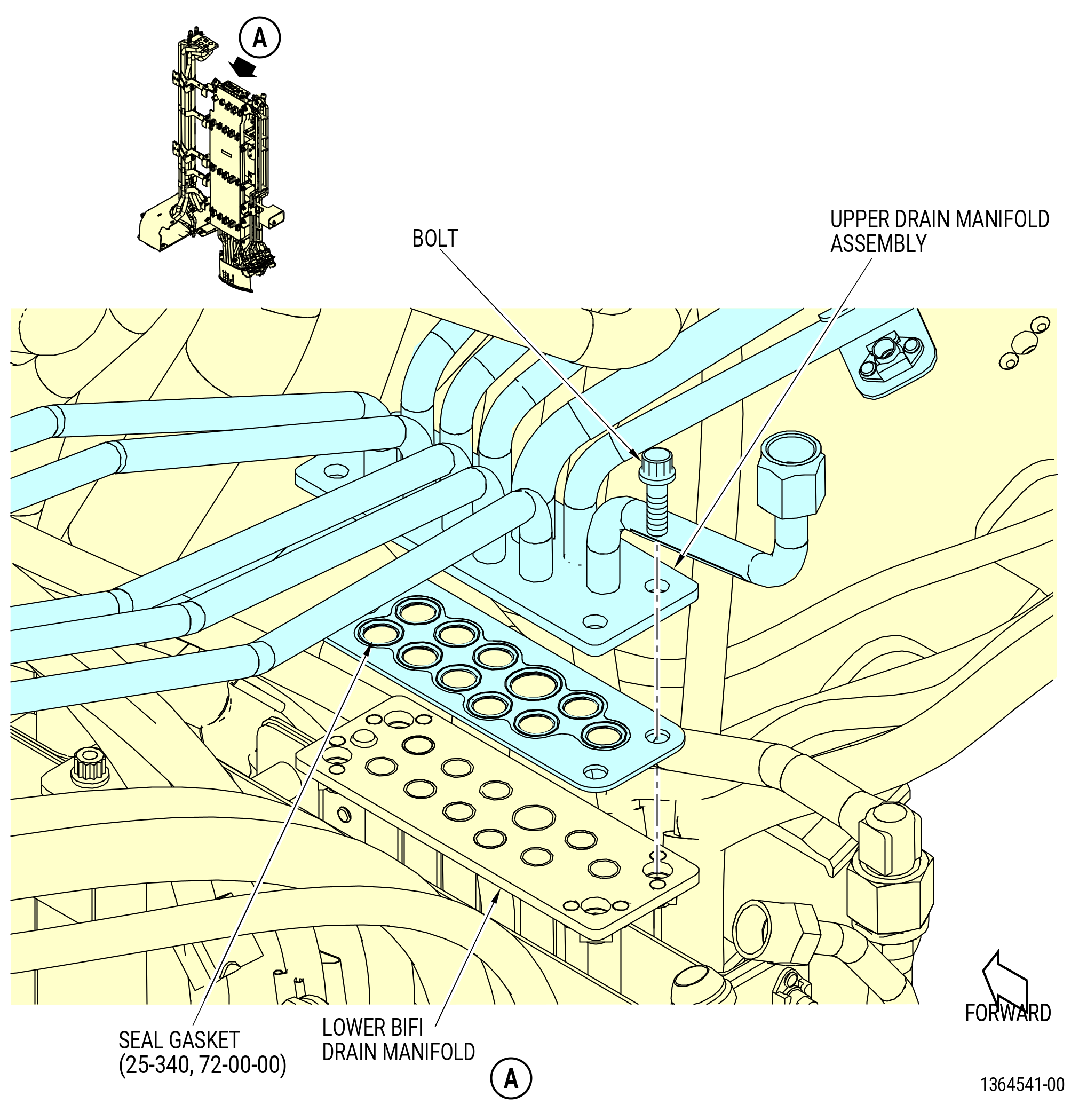
| E. | Disconnect the upper drain manifold assembly from the lower BIFI drain manifold on the top of the lower bifurcation assembly as follows. Refer to Figure 305. |
| (1) | Remove the four bolts that attach the lower BIFI drain manifold to the plate of the upper drain manifold assembly. |
| (2) | Disconnect the upper drain manifold assembly from the lower BIFI drain manifold. |
| (3) | Remove the seal gasket (25-340 , 72-00-00) (SIN 99051) from the plate on the lower BIFI drain manifold. Discard the seal gasket. |
|
|
| Subtask 72-00-03-020-022 |
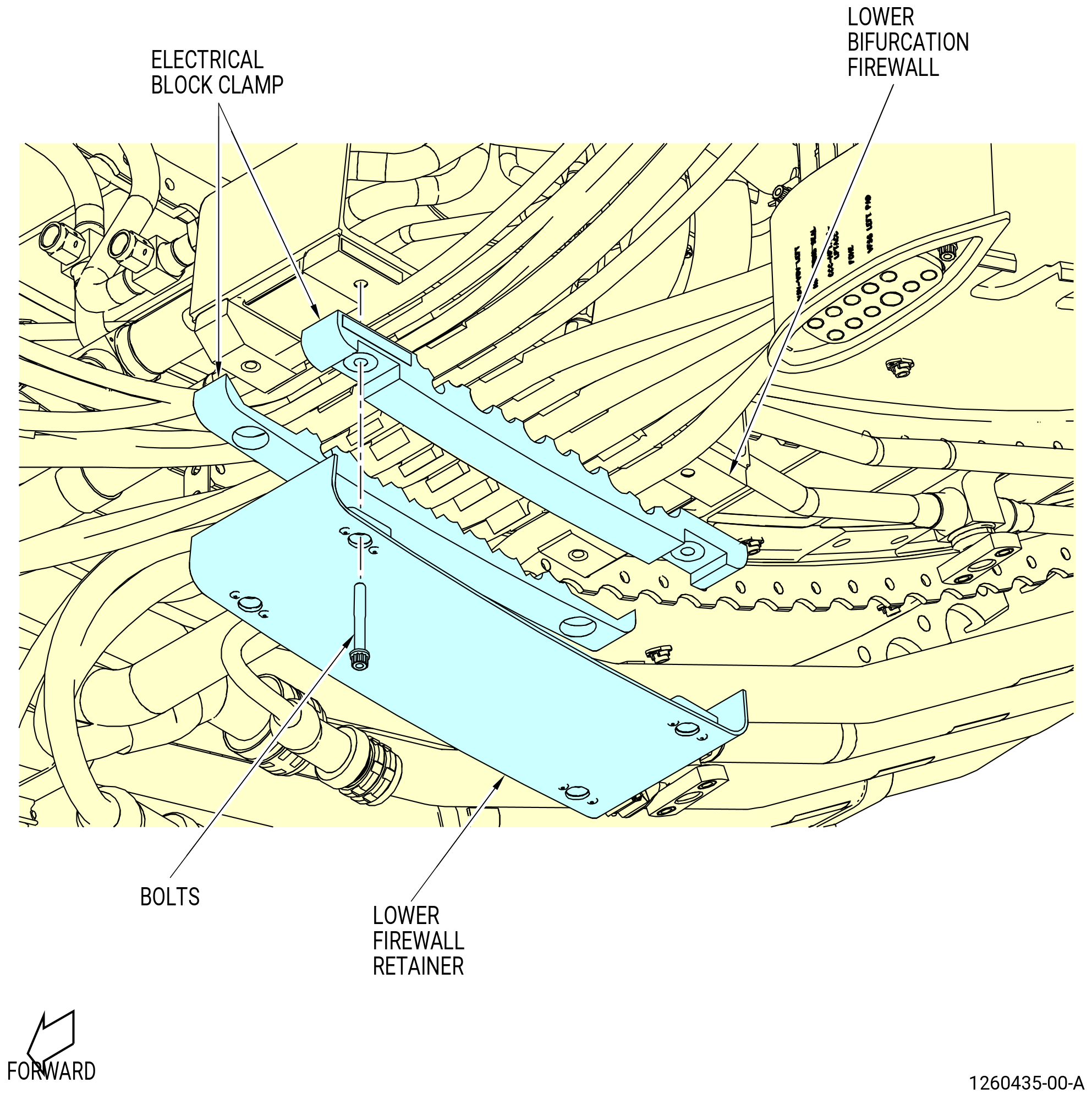
| F. | Remove the lower firewall retainer and electrical block clamp as follows. Refer to Figure 306. |
| (1) | Remove the bolts on the bottom of the lower firewall retainer. |
| (2) | Remove the lower firewall retainer and the electrical block clamps. |
| Subtask 72-00-03-020-015 |
| G. | Deleted. |
| Subtask 72-00-03-020-016 |
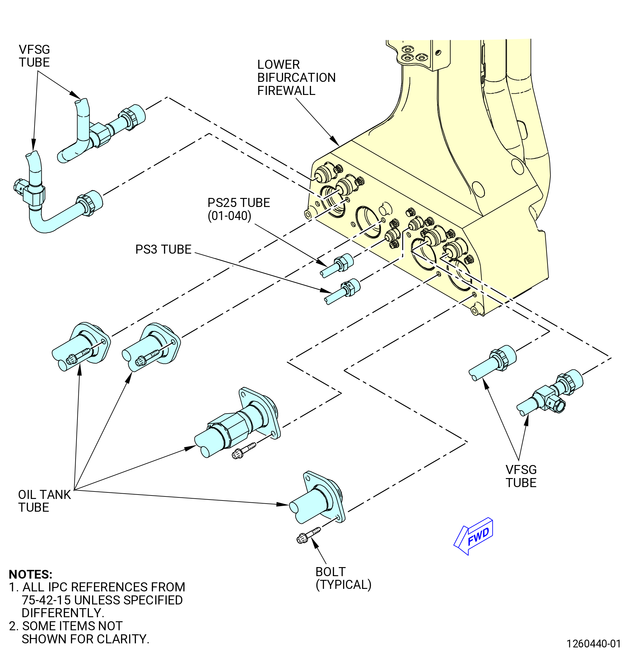
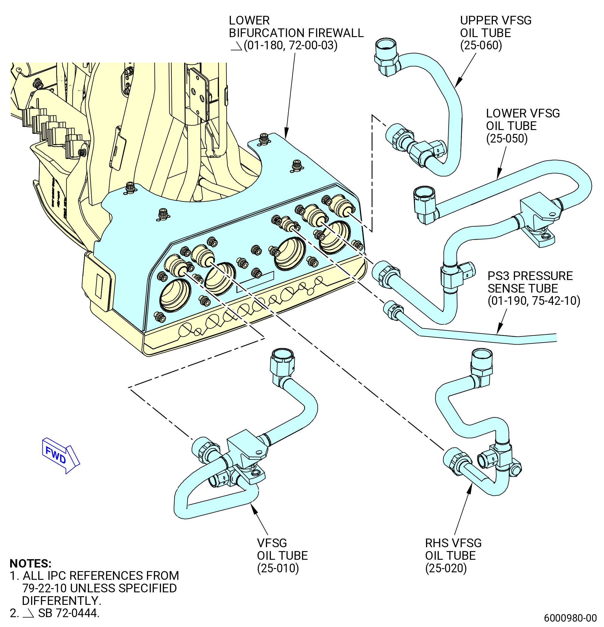
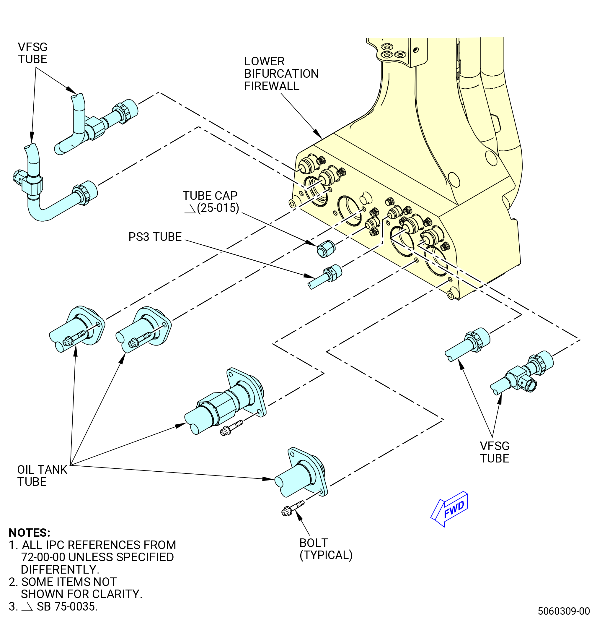
| H. | Disconnect the oil tank tubes and the variable frequency starter generator (VFSG) tubes from the bottom of the lower bifurcation firewall as follows. Refer to Figure 308. |
| (1) | Remove the eight bolts from the flanges of the oil tank tubes that are attached to the lower bifurcation firewall. |
| (2) | Remove the oil tank tubes from the lower bifurcation firewall. |
| (3) | Remove and discard the preformed packings (01-100 , 79-22-10) (SIN 44056), (05-210 , 79-22-10) (SIN 44854), (05-230 , 79-22-10) (SIN 44952), and (01-110 , 79-22-20) (SIN 45355). |
| (4) | Remove the VFSG tubes from the forward section of the lower bifurcation firewall as follows: |
| (a) | Remove the B-nuts that attach the VFSG tubes to the lower bifurcation firewall. |
| (b) | Disconnect the VFSG tubes from the lower bifurcation firewall. |
| (5) | Remove the PS3 tube from the forward section of the lower bifurcation firewall as follows: |
| (a) | Loosen the B-nut that attaches the PS3 tube to the lower bifurcation firewall. |
| (b) | Disconnect the PS3 tube from the lower bifurcation firewall. |
| Subtask 72-00-03-020-031 |
| * * * PRE SB 75-0035( Engines with PS25 Pressure Sense Tube and Air P25 Hose Tube ) |
| (6) | Remove the PS25 pressure sense tube (PS25 tube) (01-040 , 75-42-15) (SIN 61401) from the forward section of the lower bifurcation firewall as follows: |
| (a) | Loosen the B-nut that attaches the PS25 tube (01-040 , 75-42-15) (SIN 61401) to the lower bifurcation firewall. |
| (b) | Disconnect the PS25 tube (01-040 , 75-42-15) (SIN 61401) from the lower bifurcation firewall. |
| * * * END PRE SB 75-0035 |
| Subtask 72-00-03-020-032 |
| * * * SB 75-0035( Engines without PS25 Pressure Sense Tube and Air P25 Hose Tube ) |
| (6).A. | Remove the tube cap (25-015 , 72-00-00) (SIN 61460) from the forward section of the lower bifurcation firewall as follows: |
| (a) | Loosen the tube cap (25-015 , 72-00-00) (SIN 61460) attached to the lower bifurcation firewall. |
| (b) | Disconnect the tube cap (25-015 , 72-00-00) (SIN 61460) from the lower bifurcation firewall. |
| * * * END SB 75-0035 |
|
|
| Subtask 72-00-03-020-017 |
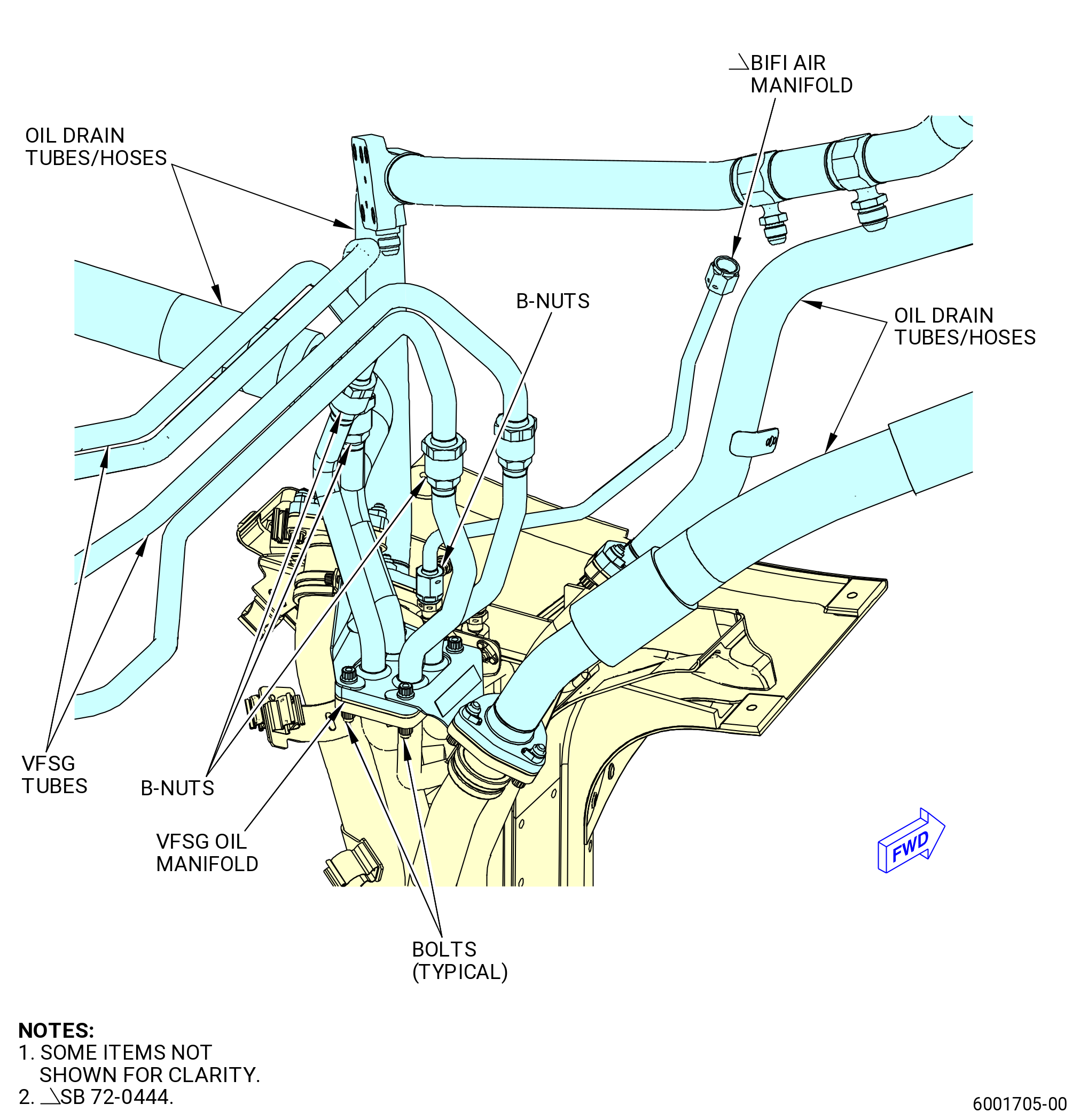
| I. | Disconnect the VFSG tubes, the pressure sense tubes, the oil drain tubes/hoses, and the VFSG oil manifold from the top forward section of the lower bifurcation assembly as follows. Refer to Figure 309. |
| (1) | Disconnect the oil drain tubes/hoses from the forward section of the lower bifurcation as follows: |
| (a) | Remove the bolts from the flanges on the oil drain tubes/hoses. |
| (b) | Remove the oil tank tubes from the forward section of the lower bifurcation tubes. |
| (c) | Remove and discard the gaskets (10-230 , 79-22-10) (SIN 44053), (10-320 , 79-22-10) (SIN 44451), (10-070 , 79-22-10) (SIN 44852), and (10-140 , 79-22-10) (SIN 45353). |
| (2) | Remove the VFSG tubes from the VFSG oil manifold tubes as follows: |
| (a) | Loosen the B-nuts that attach the VFSG tubes to the VFSG oil manifold. |
| (b) | Disconnect the VFSG tubes. |
| (3) | Remove the VSFG oil manifold from the lower bifurcation assembly as follows: |
| (a) | Remove the bolts the attaches the VFSG oil manifold to the lower bifurcation assembly. |
| (b) | Remove the VFSG oil manifold. |
| (c) | Remove and discard the gasket (30-020 , 79-22-10) (SIN 99050). |
| Subtask 72-00-03-020-033 |
| * * * PRE SB 72-0444( with PS25 Sense Line ) |
| (4) | Remove the pressure sense tubes from the forward section of the lower bifurcation assembly as follows: |
| (a) | Loosen and remove the B-nuts from the lower bifurcation assembly. |
| (b) | Remove the pressure sense tubes from the lower bifurcation assembly. |
| * * * END PRE SB 72-0444 |
| Subtask 72-00-03-020-034 |
| * * * SB 72-0444( without PS25 Sense Line ) |
| (4).A. | Remove the pressure sense tube from the forward section of the lower bifurcation assembly as follows: |
| (a) | Loosen and remove the B-nuts from the lower bifurcation assembly. |
| (b) | Remove the pressure sense tube from the lower bifurcation assembly. |
| * * * END SB 72-0444 |
|
|
| Subtask 72-00-03-020-020 |
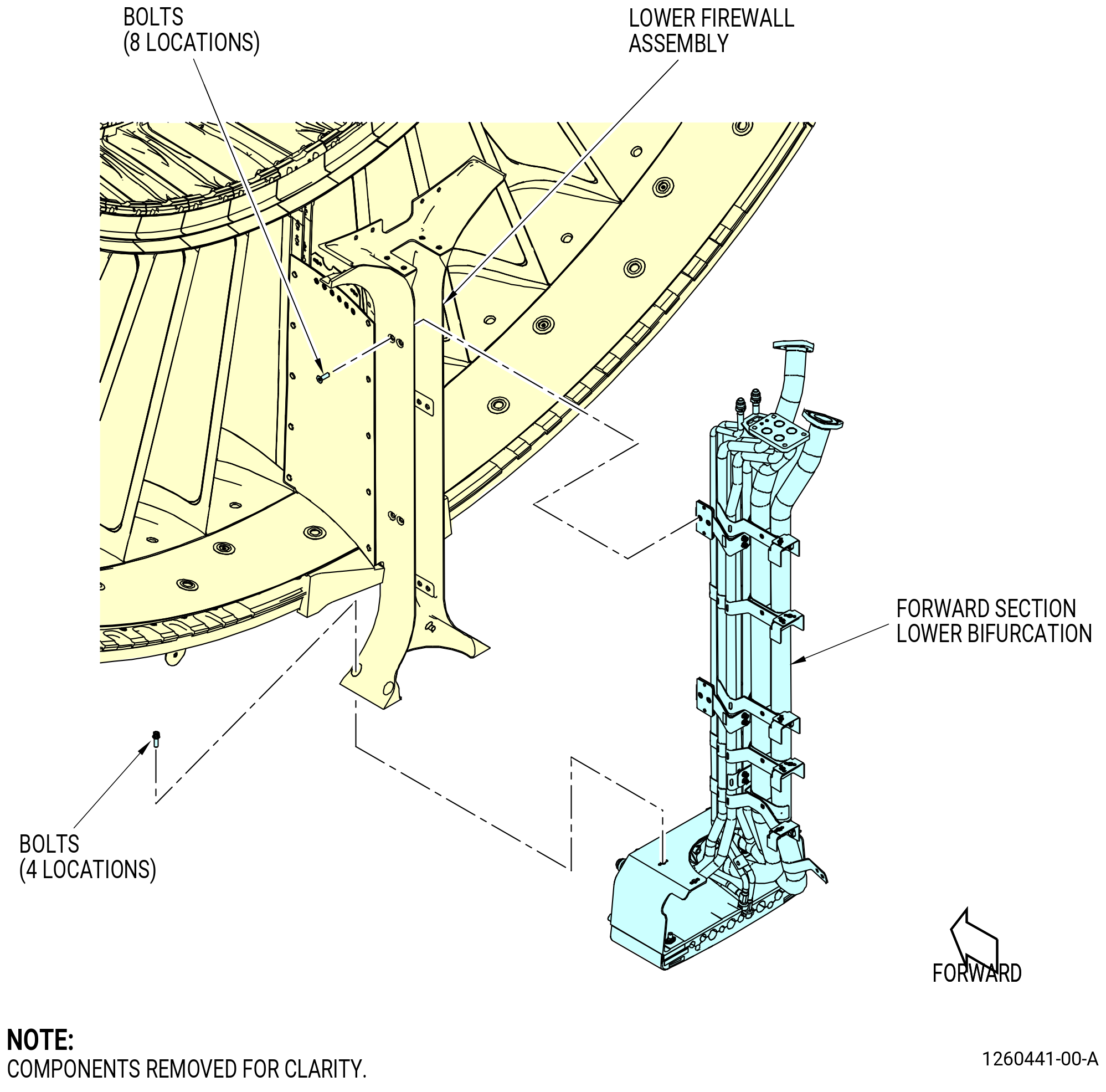
| J. | Remove the lower bifurcation assembly from the lower firewall assembly on the fan stator module assembly as follows. Refer to Figure 310. |
| CAUTION: |
|
| (1) | Make sure that the lower bifurcation assembly is correctly attached to the 11C3251 installation fixture. Refer to Subtask 72-00-03-020-021 (paragraph 3.B.). |
| (2) | Remove all the bolts that attach the lower bifurcation assembly to the lower firewall assembly. |
| (3) | Remove the lower bifurcation assembly from the lower firewall assembly on the fan stator assembly. |
| (4) | Put the lower bifurcation assembly in a safe storage location. |
| Subtask 72-00-03-020-027 |
| K. | Disassemble the lower bifurcation assembly. Refer to 72-00-03-040-802 (72-00-03, Disassembly 001). The lower bifurcation assembly will stay installed in the 11C3251 installation fixture. Refer to Figure 303. |