| GENX-1B ENGINE MANUAL | Dated: 10/31/2022 | |
| EM 72-00-03 , DISASSEMBLY 001 | ||
| LOWER BIFURCATION ASSEMBLY - DISASSEMBLY 001 | ||
| GENX-1B ENGINE MANUAL | Dated: 10/31/2022 | |
| EM 72-00-03 , DISASSEMBLY 001 | ||
| LOWER BIFURCATION ASSEMBLY - DISASSEMBLY 001 | ||
| * * * FOR ALL |
| TASK 72-00-03-040-802 |
| 1 . | General. |
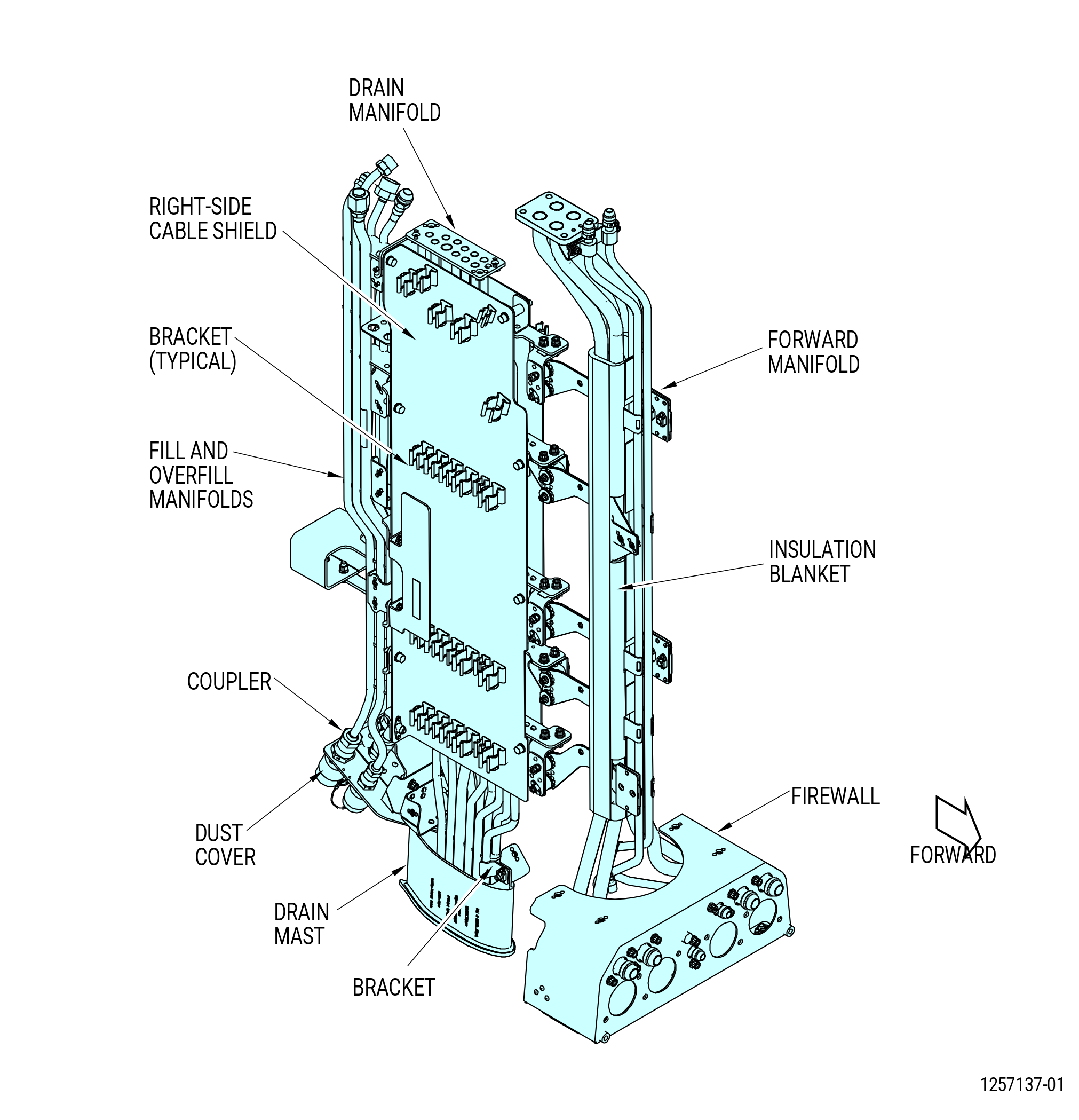
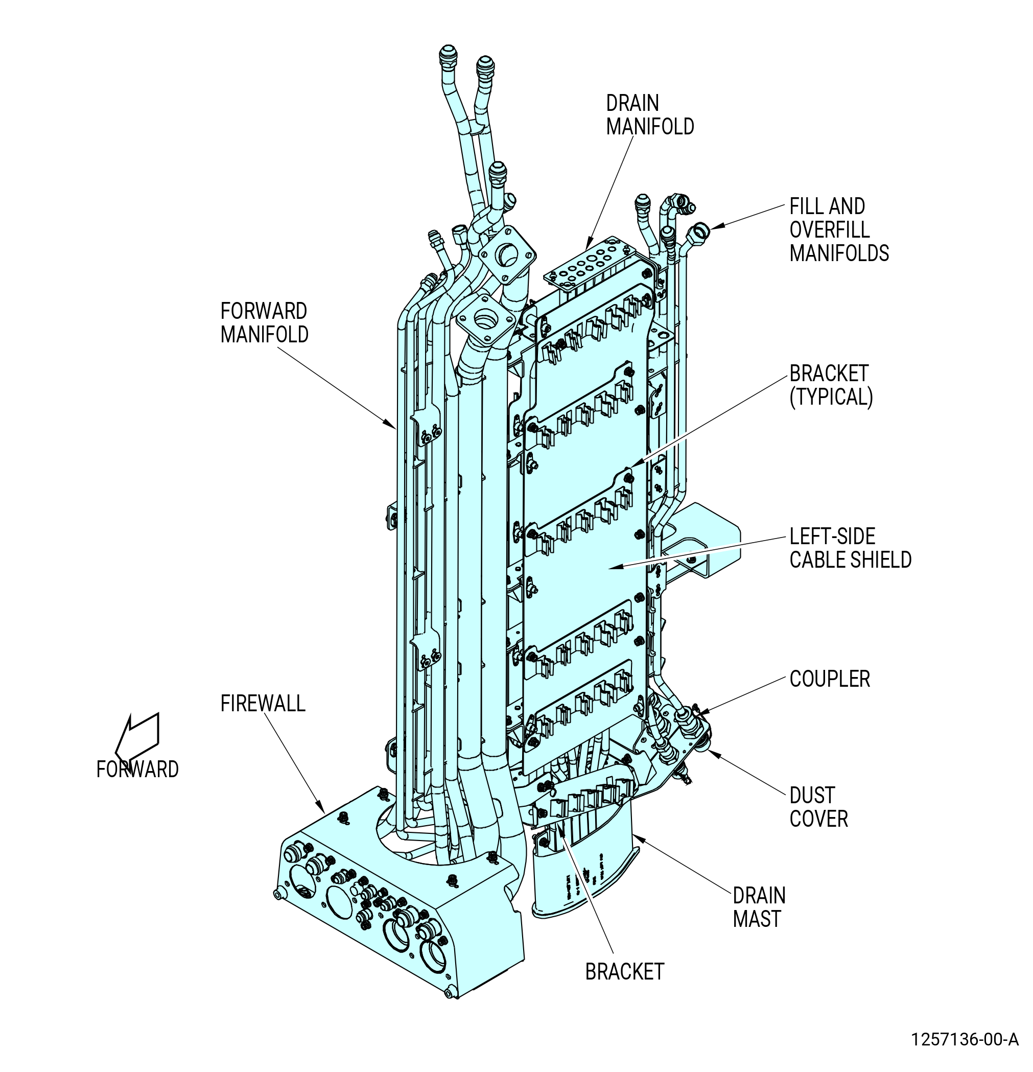
| A. | This procedure gives instructions to disassemble the lower bifurcation assembly (25-010 , 72-00-00) (SIN 09400) or (25-011 , 72-00-00) (SIN 09400). Refer to Figure 501. |
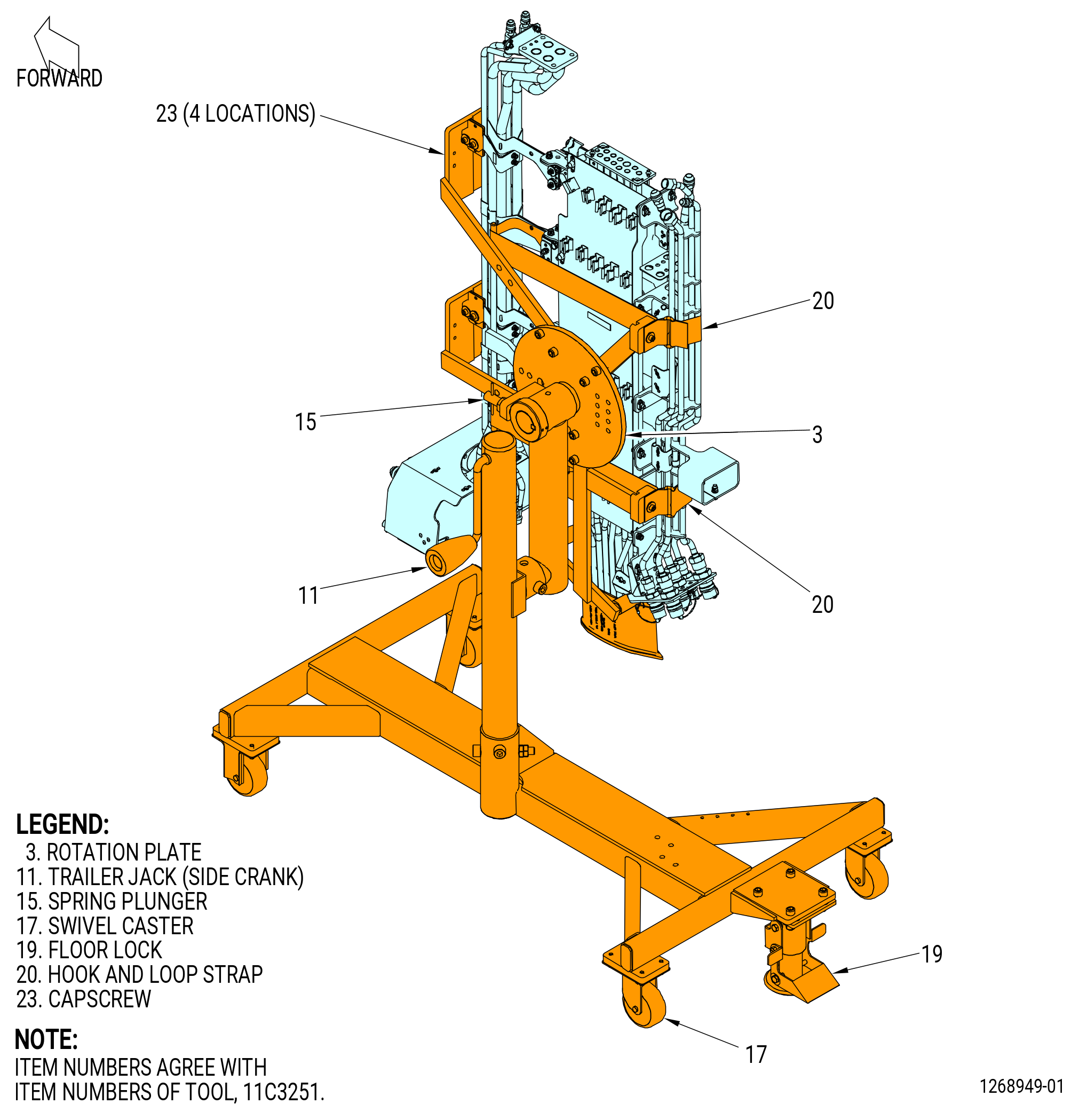
| B. | This procedure begins with the lower bifurcation assembly installed in the 11C3251 installation fixture, at the equivalent disassembly status of TASK 72-00-03-020-802 (LOWER BIFURCATION ASSEMBLY - REMOVAL) . Refer to Figure 502. |
| 2 . | Tools, Equipment, and Materials. |
| NOTE: |
|
| A. | Tools and Equipment. |
| (1) | Special Tools. |
|
| (2) | Standard Tools and Equipment. None. |
| (3) | Locally Manufactured Tools. None. |
| B. | Consumable Materials. None. |
| C. | Referenced Procedures. |
|
| D. | Expendable Parts. None. |
|
| 3 . | Procedure. |
| Subtask 72-00-03-040-016 |
| A. | Remove the caps and the couplings from the manifold plate as follows. Refer to Figure 501. |
| (1) | If necessary, rotate the lower bifurcation assembly in the 11C3251 installation fixture as follows. Refer to Figure 502. |
| CAUTION: |
|
| (a) | Make sure that the swivel casters (item 17) are in the locked (down) position and touch the floor. |
| (b) | Make sure that the hook and loop straps (item 20) are safely attached. |
| (c) | Pull on the spring plunger (item 15) to unlock the rotation plate (item 3). |
| (d) | Carefully turn the rotation plate (item 3) to a position that lets you disassemble the bifurcation assembly. |
| (e) | Re-insert the spring plunger (item 15) to lock the rotation plate (item 3). |
| (2) | Remove the safety cable from the manifold plate. |
| (3) | Remove the caps. |
| (4) | Loosen the B-nuts and hex nuts and remove the couplings and nuts. |
| Subtask 72-00-03-040-017 |
| B. | Remove the lower bifurcation firewall (firewall) as follows: |
| (1) | Remove the bolts that attach the firewall to the lower bifurcation forward manifold (forward manifold). |
| (2) | Remove the firewall from the forward manifold. |
| Subtask 72-00-03-040-019 |
| C. | Remove the lower bifurcation fill and overfill manifold (fill and overfill manifold) as follows: |
| Subtask 72-00-03-040-027 |
| * * * SB 73-0060( W30 and W31 Redesigned Harnesses ) |
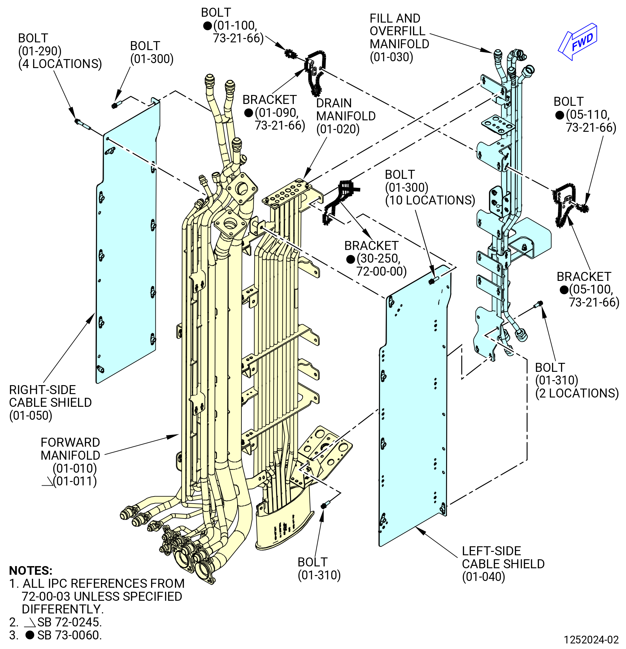
| (1) | Remove the W31 electrical harness support bracket (bracket) (30-250 , 72-00-00) (SIN 0971J), harness W30 support bracket (bracket) (01-090 , 73-21-66) (SIN 9901U), and harness W31 support bracket (bracket) (05-100 , 73-21-66) (SIN 9901T) as follows: |
| NOTE: |
|
| (a) | Remove the machine bolts (bolts) (01-300) (SIN 99022) and bolts (01-310) (SIN 99024) that attach the fill and overfill manifold (01-030) (SIN 99004) to the drain manifold (01-020) (SIN 99001) and left-side cable shield (01-040) (SIN 09710). |
| (b) | Remove the machine bolts (bolts) (01-100 , 73-21-66) (SIN 9902H) and (05-110 , 73-21-66) (SIN 9902H) that attach the brackets (01-090 , 73-21-66) (SIN 9901U) and (05-100 , 73-21-66) (SIN 9901T) to the fill and overfill manifold (01-030) (SIN 99004). |
| (c) | Remove the bolt (01-300) (SIN 99022) that attach the bracket (30-250 , 72-00-00) (SIN 0971J) to the left-side cable shield (01-040) (SIN 09710), drain manifold (01-020) (SIN 99001), and fill and overfill manifold (01-030) (SIN 99004). |
| (d) | Remove the brackets (30-250 , 72-00-00) (SIN 0971J), (01-090 , 73-21-66) (SIN 9901U), and (05-100 , 73-21-66) (SIN 9901T). |
| * * * END SB 73-0060 |
| Subtask 72-00-03-040-028 |
| (2) | Remove the bolts that attach the fill and overfill manifold to the drain manifold and right-side cable shield. |
| (3) | Remove the bolts that attach the fill and overfill manifold to the drain manifold and left-side cable shield. |
| (4) | Remove the fill and overfill manifold. |
| Subtask 72-00-03-040-020 |
| D. | Remove the left and right-side cable shields as follows: |
| (1) | Remove the bolts that attach the left-side cable shield to the right-side cable shield. |
| (2) | Remove the left and right-side cable shields from the U-shaped brackets on the drain manifold. |
| Subtask 72-00-03-040-021 |
| E. | Remove the forward bifurcation manifold (forward manifold) as follows: |
| (1) | Remove the bolts that attach the forward manifold to the drain manifold and support brackets. |
| (2) | Remove the forward manifold from the drain manifold. |
| Subtask 72-00-03-040-025 |
| * * * SB 72-0035( Bifurcation Assembly with Insulation Blanket ) |
| F. | Remove the insulation blanket (01-360) (SIN 99090) from the forward manifold as follows: |
| NOTE: |
|
| (1) | Open the snap button fasteners that connect the insulation blanket to the forward manifold. |
| (2) | Remove the insulation blanket (01-360) (SIN 99090) from the forward manifold. |
| * * * END SB 72-0035 |
| Subtask 72-00-03-040-022 |
| * * * PRE SB 72-0223( Installation of Drain Manifold with Support Bracket ) |
| G. | Remove the lower bifurcation drain manifold (drain manifold) as follows: |
| (1) | Remove the bolts that attach the drain manifold and support bracket to the drain mast. |
| (2) | Remove the drain mast and support bracket from the drain manifold. |
| (3) | Remove the drain manifold from the support brackets. |
| * * * END PRE SB 72-0223 |
| Subtask 72-00-03-040-026 |
| * * * SB 72-0223( Installation of Drain Manifold without Support Bracket ) |
| G.A. | Remove the drain manifold as follows: |
| (1) | Remove the bolts that attach the drain manifold to the drain mast. |
| (2) | Remove the drain mast from the drain manifold. |
| (3) | Remove the drain manifold from the support brackets. |
| * * * END SB 72-0223 |
| Subtask 72-00-03-040-024 |
| H. | Remove the support brackets (brackets) as follows: |
| (1) | Remove the bolts that attach the support brackets to the left/right side cable shields, the drain manifold, and the forward manifold. |
| (2) | Remove the bolts that attach a bracket to a different bracket. |
| (3) | Remove the brackets. |
| Subtask 72-00-03-040-029 |
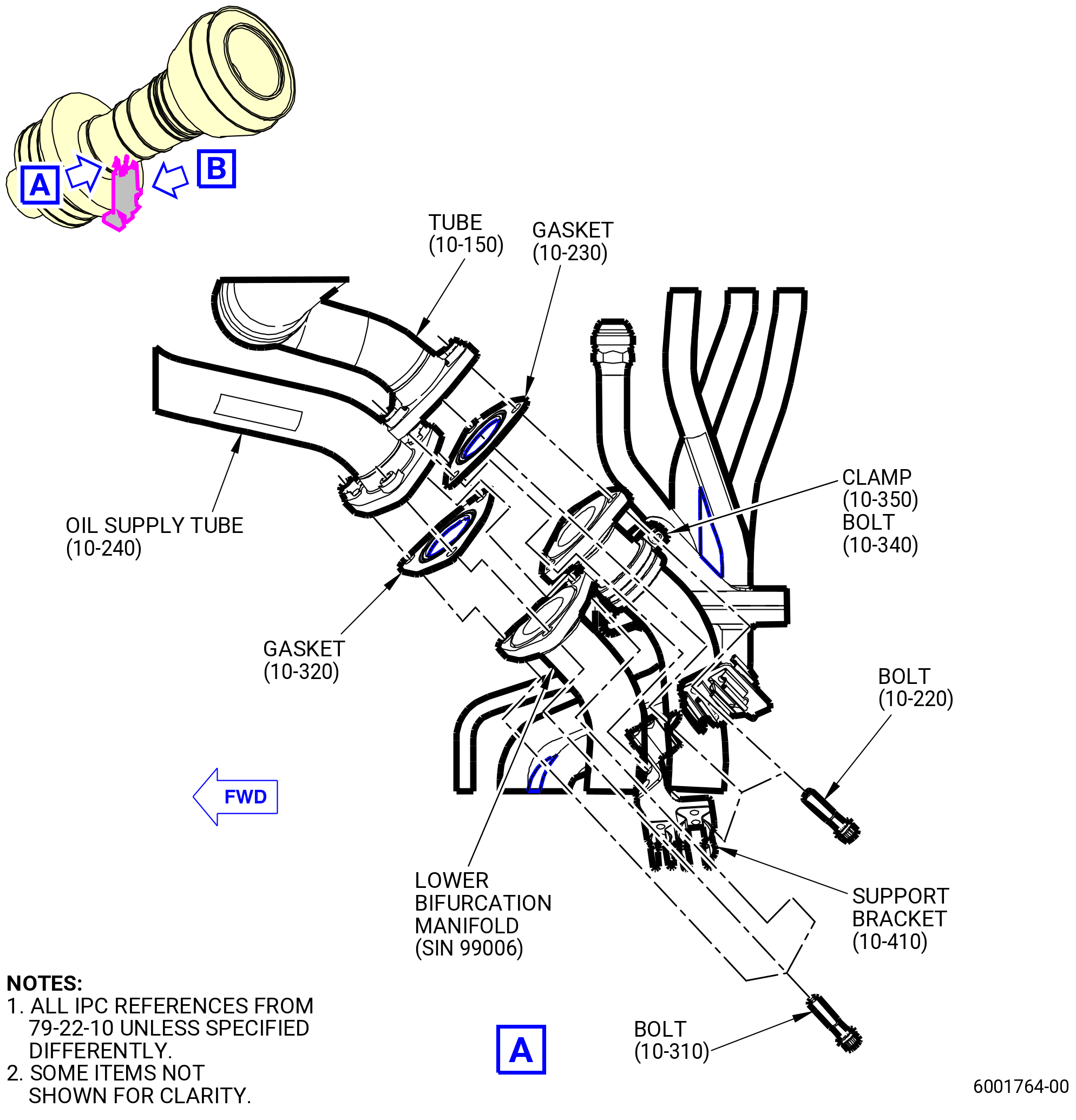
| I. | Remove the lower bifurcation manifold (SIN 99006). Refer to Figure 503 and do as follows: |
| (1) | Remove the three bolts (10-310 , 79-22-10) (SIN 44422). Remove and discard the gasket (10-320 , 79-22-10) (SIN 44451). |
| (2) | Remove the three bolts (10-220 , 79-22-10) (SIN 44024). Remove and discard the gasket (10-230 , 79-22-10) (SIN 44053). |
| (3) | Remove the bolt (10-340 , 79-22-10) (SIN 9902D) attached to the clamp (10-350 , 79-22-10) (SIN 99085). |
| (4) | Remove the two bolts (01-090 , 79-22-10) (SIN 44026). |
| (5) | Disconnect the oil return tube (01-010 , 79-22-10) (SIN 44000). |
| (6) | Remove the two bolts (10-220 , 79-22-10) (SIN 44924). |
| (7) | Disconnect the air/oil cooler tube hose (ACOC tube) (05-050 , 79-22-10) (SIN 44900). |
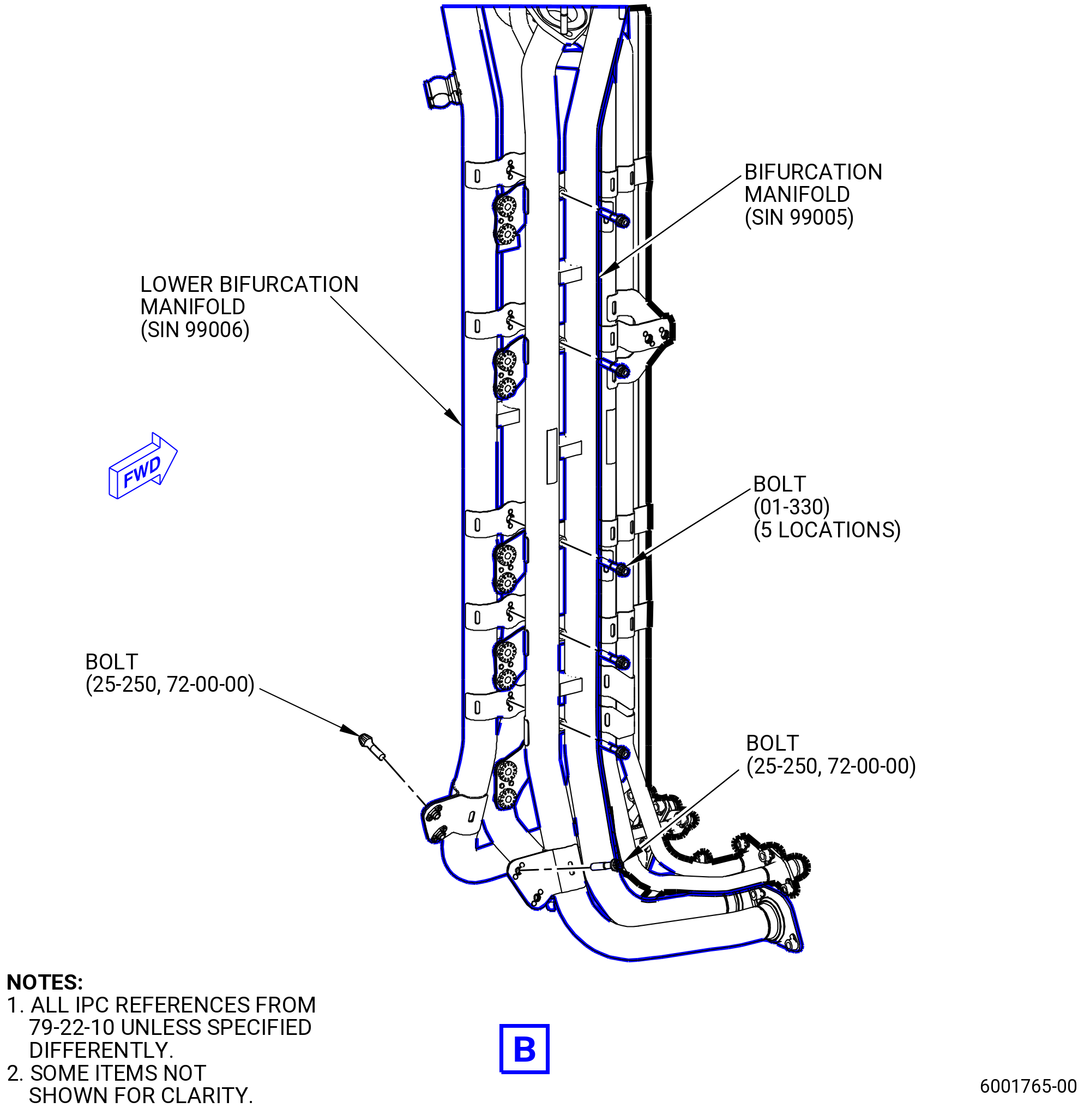
| (8) | Remove the bolts (25-250 , 72-00-00) (SIN 67126). |
| (9) | Remove the five bolts (10-330 , 79-22-10) (SIN 99028). |
| (10) | Remove the lower bifurcation manifold (SIN 99006). |