| GENX-1B ENGINE MANUAL | Dated: 09/30/2024 | |
| EM 72-57-00 , ASSEMBLY 001 | ||
| TURBINE REAR FRAME ASSEMBLY - ASSEMBLY 001 | ||
| GENX-1B ENGINE MANUAL | Dated: 09/30/2024 | |
| EM 72-57-00 , ASSEMBLY 001 | ||
| TURBINE REAR FRAME ASSEMBLY - ASSEMBLY 001 | ||
| * * * FOR ALL |
| TASK 72-57-00-440-801 |
| 1 . | General. |
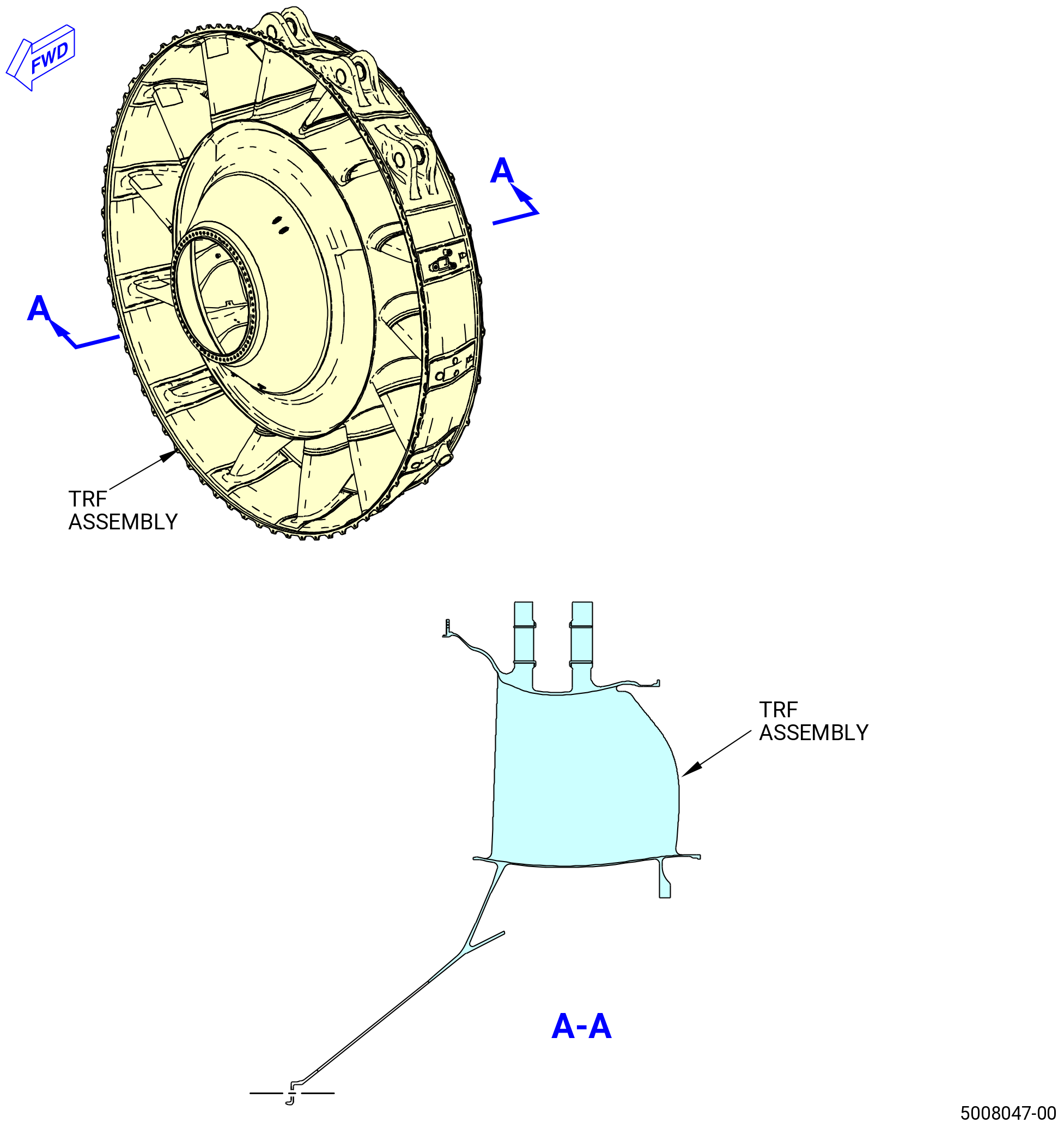
| A. | This procedure gives instructions to assemble the turbine rear frame (TRF) assembly (TRF assembly). Refer to Figure 1001. |
| • |
|
| • |
|
| • |
|
| B. | If not already attached, attach the TRF to the 9429M60 assembly stand. Refer to Subtask 72-57-00-440-001 (paragraph 3.B.) thru Subtask 72-57-00-440-004 (paragraph 3.E.). |
| • |
|
| • |
|
| C. | Install covers on spare assemblies only. |
| D. | Install all the bolts with the heads up and/or forward unless specific instructions are given. |
| E. | Apply the lubricants to the threads and the friction surfaces only. |
| WARNING: |
|
| WARNING: |
|
| WARNING: |
|
| F. | Make sure that the mating surfaces on all the flange faces are clean and have no raised metal. If necessary, clean the flanges and threads of studs with C04-002 Stoddard solvent, C04-003 acetone, or C04-035 isopropyl alcohol. |
| G. | The torque values given in this procedure are the actual torque values to apply to the fastener. If a torque multiplier is used, do the necessary calculations to find the specified torque and the value that appears on the scale or dial of the torque wrench. Refer to TASK 70-51-00-400-004 (TIGHTENING PRACTICES AND TORQUE VALUES) . |
| H. | Follow the instructions to safety parts with safety wire, safety cable, cotter pins, or tab washers. Refer to TASK 70-11-00-400-001 (FASTENER RETENTION PROCEDURES) . |
| 2 . | Tools, Equipment, and Materials. |
| NOTE: |
|
| A. | Tools and Equipment. |
| (1) | Special Tools. |
| (2) | Standard Tools and Equipment. None. |
| (3) | Locally Manufactured Tools. None. |
| B. | Consumable Materials. |
|
| C. | Referenced Procedures. |
|
| D. | Expendable Parts. |
|
| 3 . | Procedure. |
| Subtask 72-57-00-220-001 |
| A. | Do a visual inspection of the TRF for unwanted materials and handling damage. |
| Subtask 72-57-00-440-001 |
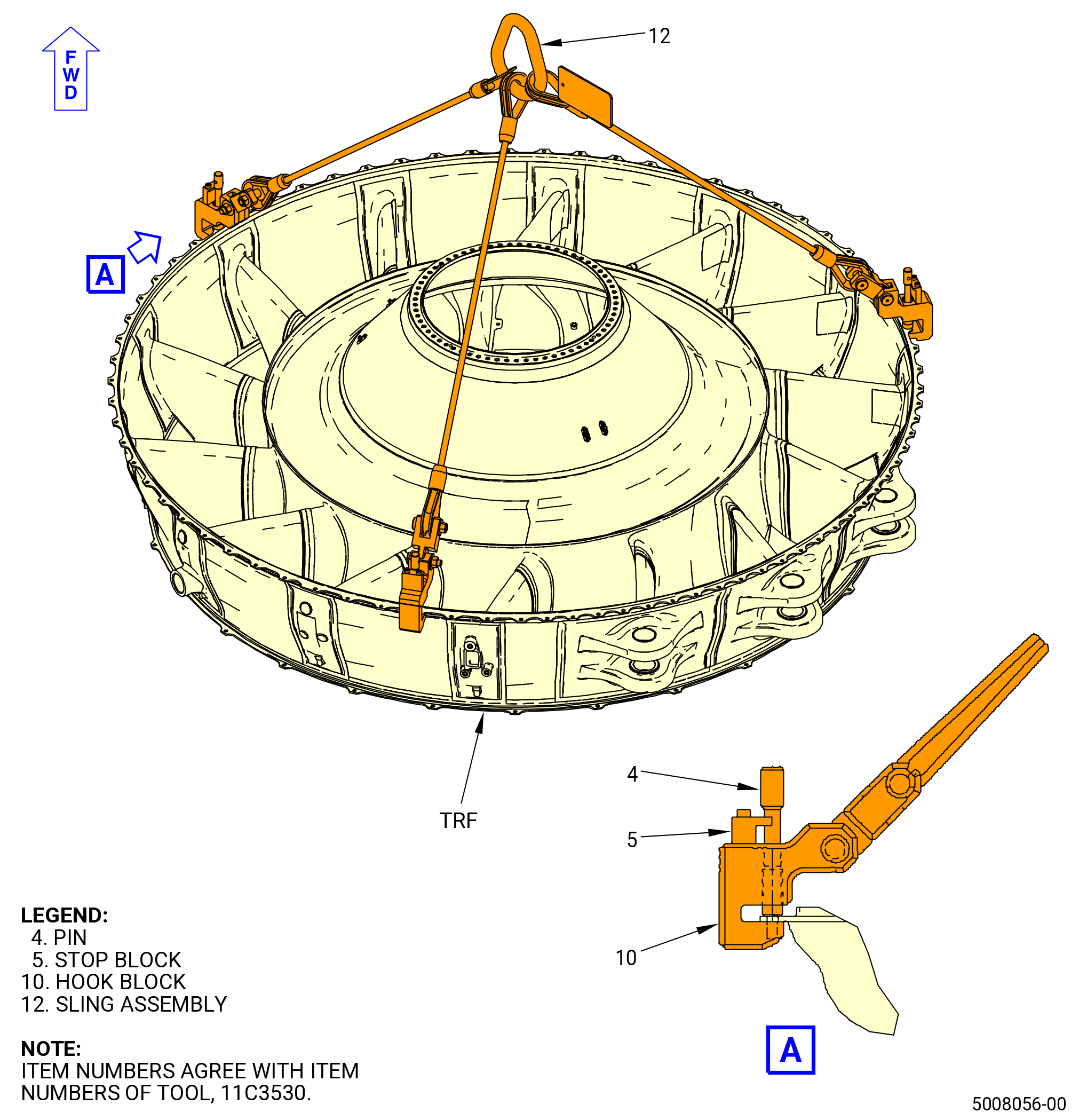
| B. | Attach the 11C3530 lift fixture to the TRF. Refer to Figure 1002 and do as follows: |
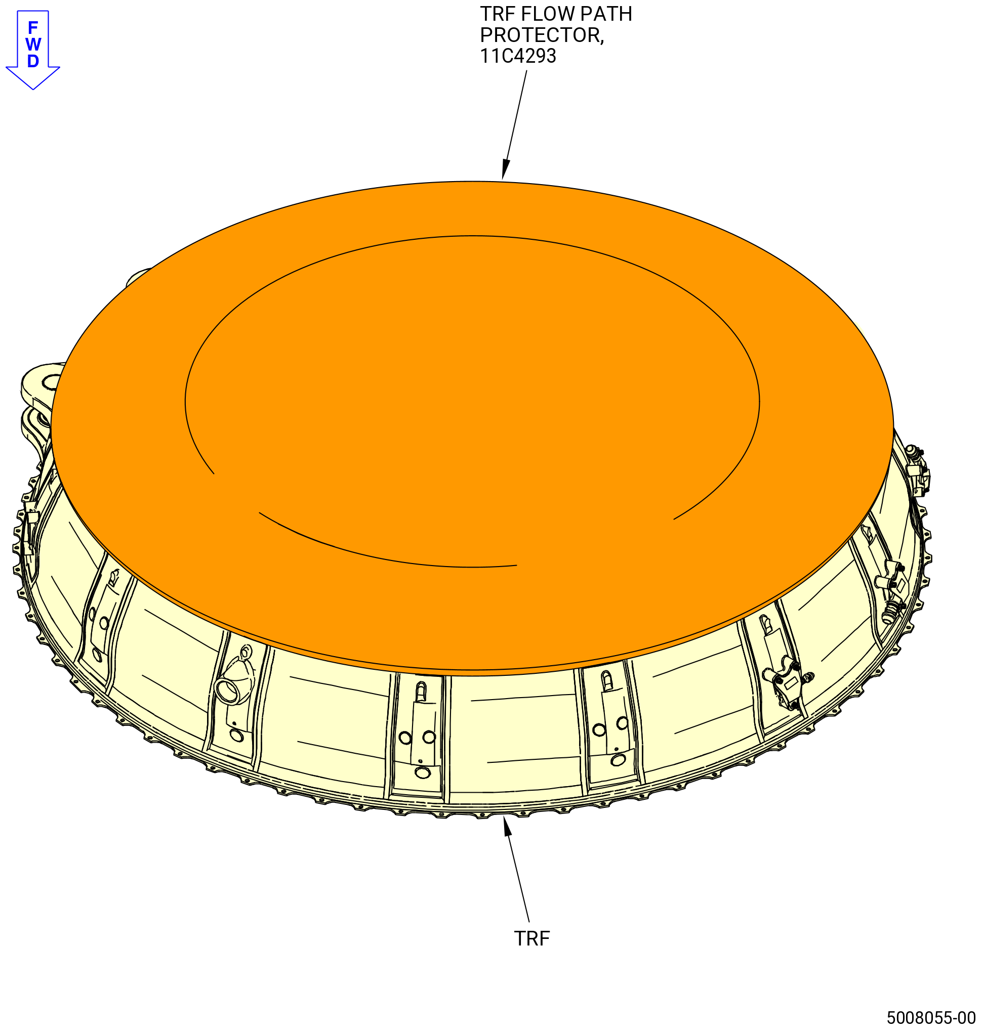
| (1) | Remove the 11C4293 TRF flow path protector from the aft side of the TRF. |
| (2) | Attach the sling assembly (item 12) to an overhead hoist. |
| (3) | Turn the pins (item 4) counterclockwise (CCW) away from the stop block (item 5). |
| (4) | Attach the hook block (item 10) to the flange of the TRF at three equally spaced locations as follows: |
| (a) | Align the holes in the hook blocks (item 10) with the holes in the flange of the TRF. |
| (b) | Turn the pins (item 4) clockwise (CW) to engage the threads in the hook blocks (item 10). Tighten the pins (item 4) hand-tight. |
| Subtask 72-57-00-440-002 |
| C. | Attach the 11C3516 bracket set to the TRF as follows: |
| WARNING: |
|
| (1) | Lift the TRF with the 11C3530 lift fixture to a position where you can easily install the 11C3516 bracket set. |
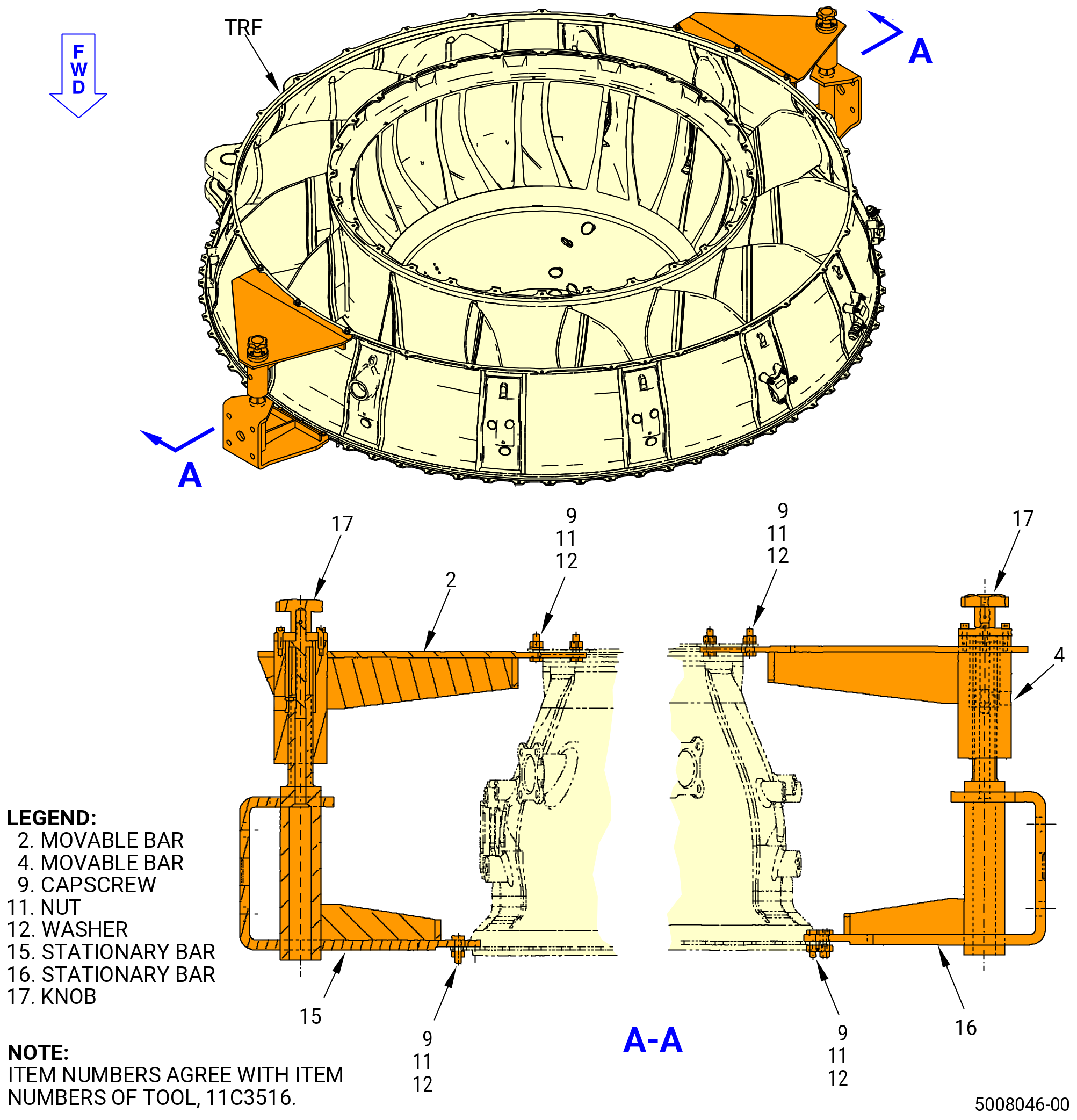
| (2) | Attach the movable bars (items 2 and 4) and the stationary bars (items 15 and 16) at the 3:00 o'clock and 9:00 o'clock positions to the TRF as follows. Refer to Figure 1003. |
| (a) | Adjust the movable bars (items 2 and 4) in, by turning the hand knob CW. |
| (b) | Align the holes of the stationary bars (items 15 and 16) with the holes on the forward side of the TRF forward flange. |
| (c) | Adjust the movable bars (items 2 and 4) out by turning the knob (item 17) CCW. |
| (d) | Align the holes of the movable bars (items 2 and 4) with the holes on the aft side of the TRF aft flange. |
| (e) | Install the capscrews (item 9) through the stationary bars (items 15 and 16) and the forward flange of the TRF. |
| (f) | Install the washers (item 12) and the nuts (item 11) on the capscrews (item 9) and tighten. |
| (g) | Install the capscrews (item 9) through the movable bars (items 2 and 4) and the aft flange of the TRF. |
| (h) | Install the washers (item 12) and the nuts (item 11) on the capscrews (item 9) and tighten. |
| (3) | Attach the movable bars (items 2 and 4) at the 3:00 o'clock and 9:00 o'clock positions on the TRF as follows: |
| (a) | Put the movable bars (items 2 and 4) on the stationary bars (items 15 and 16) and secure them with the knob (item 17). The movable bars (items 2 and 4) will be positioned on the aft side of the TRF rear flange. |
| (b) | Adjust the movable bar (items 2 and 4) out, by turning the hand knob (item 17) CCW. |
| Subtask 72-57-00-440-003 |
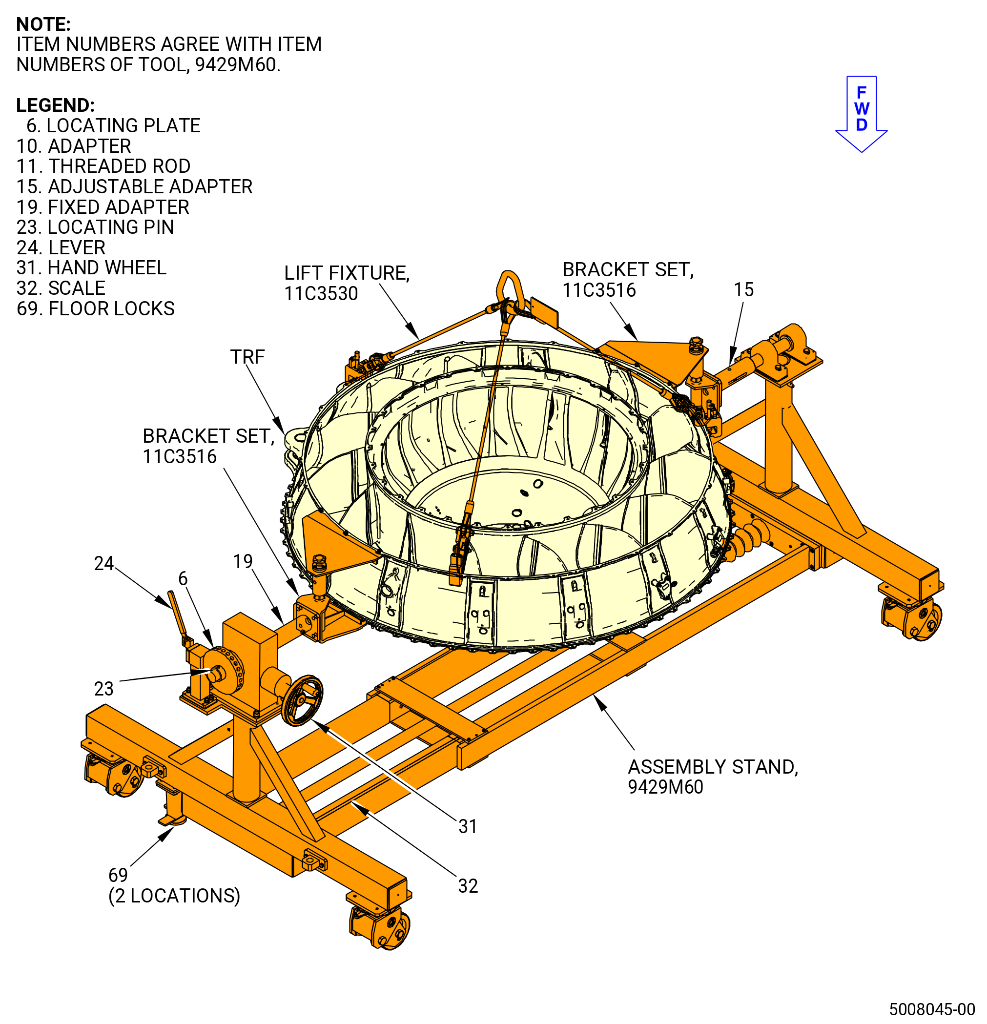
| D. | Attach the TRF to the 9429M60 assembly stand. Refer to Figure 1004 and do as follows: |
| CAUTION: |
|
| (1) | Lower the floor locks (item 69) of the 9429M60 assembly stand until they touch the floor. The floor locks must stay in contact with the floor to prevent movement of the roll-over stand. Make sure that the roll-over stand is level. |
| CAUTION: |
|
| (2) | Move the lever (item 24) to engage the locating pin in the locating plate (item 6). |
| (3) | Align the TRF with the 9429M60 assembly stand as follows: |
| (a) | Align the boltholes in one bracket of the 11C3516 bracket set with the boltholes in the fixed adapter (item 19) of the 9429M60 assembly stand. |
| (b) | Align the boltholes in the other bracket of the 11C3516 bracket set with the boltholes in the adjustable adapter (item 15) of the 9429M60 assembly stand. |
| (4) | Install the hardware that attaches the 11C3516 bracket set to the 9429M60 assembly stand as follows: |
| (a) | Install 0.50 inch (12.7 mm) diameter by 2.00 inch (50.0 mm) long slave bolts where the fixed adapter (item 19) and the adjustable adapter (item 15) of the 9429M60 assembly stand are attached to the stationary bars (items 15 and 16) of the 11C3516 bracket set. |
| (b) | Install the washers and nuts on the bolts and tighten the nuts. |
| Subtask 72-57-00-440-004 |
| E. | Remove the 11C3530 lift fixture from the TRF. Refer to Figure 1002 and do as follows: |
| (1) | Turn the pins (item 4) CCW away from the stop block (item 5). |
| (2) | Remove the hook block (item 10) from the flange of the TRF at three locations. |
| WARNING: |
|
| (3) | Lift the 11C3530 lift fixture from the TRF. |
| Subtask 72-57-00-440-005 |
| F. | Attach the 11C3530 lift fixture to the No. 5 bearing support housing (01501) as follows. Refer to Figure 1005. |
| (1) | If necessary, attach the sling assembly (item 12) to an overhead hoist. |
| (2) | Turn the pins (item 4) CCW away from the stop block (item 5). |
| (3) | Attach the hook block (item 10) to the flange of the TRF at three equally spaced locations as follows: |
| (a) | Align the holes in the hook blocks (item 10) with the holes in the flange of the TRF. |
| (b) | Turn the pins (item 4) CW to engage the threads in the hook blocks (item 10). Tighten the pins (item 4) hand-tight. |
| Subtask 72-57-00-440-006 |
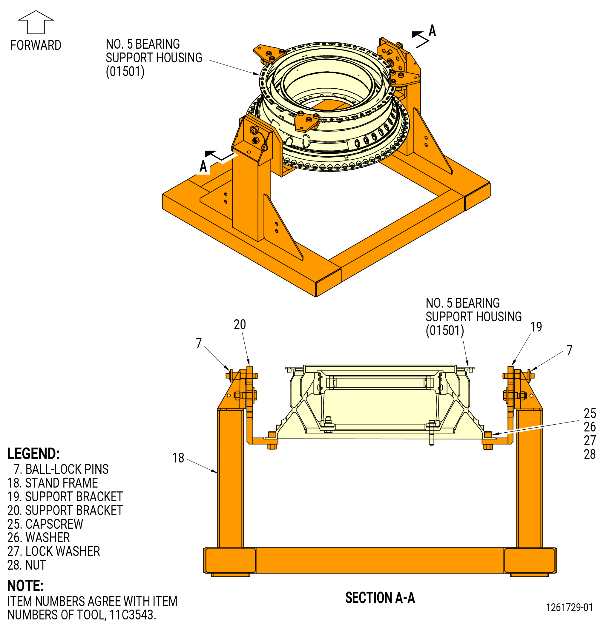
| G. | Attach the No. 5 bearing support housing (01501) to the 11C3543 buildup fixture as follows. Refer to Figure 1006. |
| WARNING: |
|
| CAUTION: |
|
| CAUTION: |
|
| (1) | Lift the No. 5 bearing support housing and make sure that the surfaces are clean. |
| (2) | Lower the No. 5 bearing support housing to the correct position on the 11C3543 buildup fixture. |
| (3) | Attach the No. 5 bearing support housing 11C3543 buildup fixture as follows: |
| (a) | Align the holes of the No. 5 bearing support housing with the holes in the support brackets (items 19 and 20). |
| (b) | Install the capscrews (item 25), flat washers (item 26), lock washers (item 27), and nuts (item 28) at two locations on each support bracket. Tighten the nuts. |
| Subtask 72-57-00-440-007 |
| H. | Remove the 11C3530 lift fixture from the No. 5 bearing support housing (01501) as follows. Refer to Figure 1005. |
| CAUTION: |
|
| CAUTION: |
|
| (1) | Turn the pins (item 4) CCW to move them out away from the hook blocks (item 10). |
| (2) | Remove the hook blocks (item 10) from the housing flange. |
| (3) | Lift the 11C3530 lift fixture from the No. 5 bearing support housing. |
| Subtask 72-57-00-440-008 |
| I. | Install the No. 5 bearing (No. 5 bearing) (01500) into the No. 5 bearing support housing (01501) as follows. Refer to Figure 1007. |
| CAUTION: |
|
| CAUTION: |
|
| (1) | Put the No. 5 bearing on a clean work table, with the forward face down. |
| Subtask 72-57-00-220-003 |
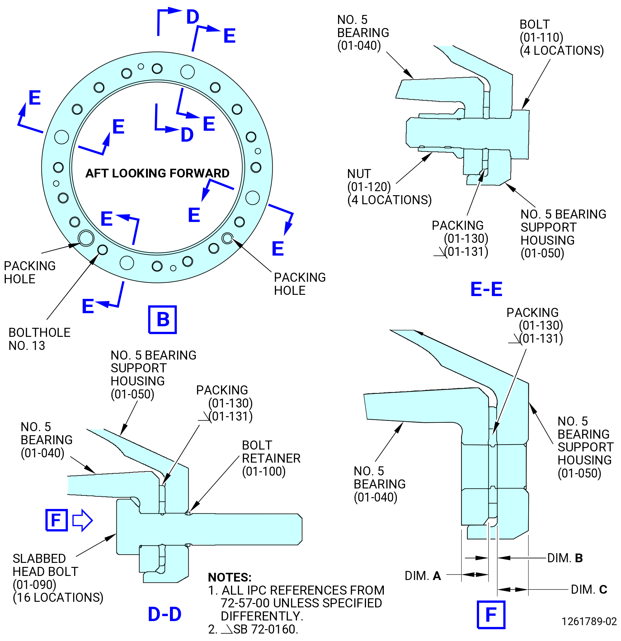
| (2) | Measure the No. 5 bearing support housing (01-050) (SIN 01501), No. 5 bearing (01-040) (SIN 01500) aft flange, and packing (01-130) (SIN 01556) or (01-131) (SIN 01556) thickness. Refer to Figure 1007 and do as follows: |
| (a) | Measure the No. 5 bearing support housing (01501) inner aft flange at four equally spaced locations. Record as Dim. C. |
| (b) | Measure the No. 5 bearing (01500) aft flange inner aft flange at four equally spaced locations. Record as Dim. A. |
| (c) | Measure the packing (01-130) (SIN 01556) or (01-131) (SIN 01556) thickness at four equally spaced locations. Record as Dim. B. |
| (d) | Calculate the total thickness of the three measurements and record as Dim. D estimated. |
| Subtask 72-57-00-640-019 |
| WARNING: |
|
| (3) | Apply a thin coating of C02-019 engine oil or C02-023 engine oil on the piston rings (01-140) (SIN 01554) and the packing (01-130) (SIN 01556) or (01-131) (SIN 01556). |
| Subtask 72-57-00-440-035 |
| CAUTION: |
|
| (4) | Install the packing (01-130) (SIN 01556) or (01-131) (SIN 01556) on the aft side of the No. 5 bearing (01-040) (SIN 01500) flange as follows: |
| (a) | Make sure the packing (01-130) (SIN 01556) or (01-131) (SIN 01556) is set to the larger packing hole at the 7:30 o'clock position (ALF) between boltholes No. 13 and 14. |
| CAUTION: |
|
| CAUTION: |
|
| (5) | Install the slabbed head bolts (01-090) (SIN 01522) at 16 locations into the No. 5 bearing (01-040) (SIN 01500) flange and through the packing (01-130) (SIN 01556) or (01-131) (SIN 01556) with the flat part of the bolthead against the bearing cage. |
| Subtask 72-57-00-640-004 |
| (6) | Apply C02-008 petrolatum in small quantities at four equally spaced locations on the lead-in chamfers of the groove in the No. 5 bearing. |
| Subtask 72-57-00-440-036 |
| CAUTION: |
|
| CAUTION: |
|
| CAUTION: |
|
| CAUTION: |
|
| NOTE: |
|
| (7) | Install the piston rings (01554) at two locations into the groove of the No. 5 bearing. Make sure that each piston ring is installed with the pressure side inward on the No. 5 bearing (01500) and the end joints point away. Refer to Figure 1007. |
| (8) | Clean the No. 5 bearing support housing (01501) aft inner flange and the No. 5 bearing (01500) aft flange with a C10-182 cleaning cloth. |
| Subtask 72-57-00-640-005 |
| (9) | Apply C02-058 lubricant to the threads and washer faces of the bolts (01528) and the nuts (01546). |
| NOTE: |
|
| Subtask 72-57-00-440-009 |
| WARNING: |
|
| WARNING: |
|
| (10) | Use a heat gun to equally increase the temperature of the full circumference of the mating aft rabbet flange of the No. 5 bearing (01-040) (SIN 01500). Apply heat for a minimum of 15-20 minutes. |
| Subtask 72-57-00-440-010 |
| CAUTION: |
|
| (10).A. | Deleted. |
| Subtask 72-57-00-440-011 |
| WARNING: |
|
| (11) | Install the No. 5 bearing (01500) into the No. 5 bearing support housing (01501). Make sure that the piston rings (01554) are fully against the No. 5 bearing before the bearing is fully installed into the No. 5 bearing support housing. |
| (12) | Install the bolts (01-110) (SIN 01528) into the boltholes No. 2, 7, 12, and 17 with the boltheads forward in the No. 5 bearing support housing (01-050) (SIN 01501) aft flange, No. 5 bearing (01-040) (SIN 01500) flange, and packing (01-130) (SIN 01556) or (01-131) (SIN 01556). |
| (13) | Install the nuts (01546) on the bolts (01528). |
| (14) | Torque the nuts (01546) to 165 lb in. (18.7 N.m) in a criss-cross pattern. |
| Subtask 72-57-00-220-004 |
| (15) | Measure Dim. D on the No. 5 bearing (01500) flange and the No. 5 bearing support housing (01501) inner aft flange at four equally spaced locations. Record as Dim. D actual. The Dim. D actual must be plus or minus 0.0015 inch (0.038 mm) of Dim. D estimated in Subtask 72-57-00-220-003 (paragraph 3.I.(2)(d)) . |
| Subtask 72-57-00-440-037 |
| (16) | Torque the nuts (01546) to 200-240 lb in. (22.6-27.1 N.m) in a criss-cross pattern. |
| (17) | Torque the nuts (01546) a second time to 200-240 lb in. (22.6-27.1 N.m) in a criss-cross pattern. |
| CAUTION: |
|
| CAUTION: |
|
| CAUTION: |
|
| (18) | Install the bolt retainers (01-100) (SIN 01594) in the groove on the slabbed head bolts (01522). |
| (19) | Make sure that the retainer is correctly installed. |
| Subtask 72-57-00-640-001 |
| J. | Apply C02-050 preservation oil to all exposed surfaces of the No. 5 bearing (01500). |
| Subtask 72-57-00-440-013 |
| K. | Put a protective cover on the No. 5 bearing (01500) to protect the outer race from unwanted material. |
| Subtask 72-57-00-710-001 |
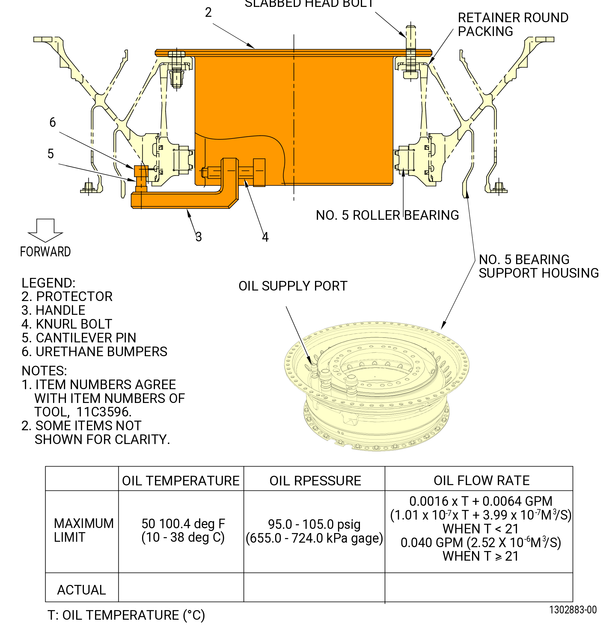
| L. | Do a flow check of the No. 5 bearing (01500) (No. 5 bearing damper flow) as follows. Refer to Figure 1008. |
| (1) | Pull the ball-lock pins (item 7) on the 11C3543 buildup fixture and turn the No. 5 bearing support housing assembly (01501) until the aft end points up. Install the ball-lock pins (item 7). Refer to Figure 1006. |
| (2) | Attach the 11C3596 flow check fixture to the No.5 bearing support housing (01501) as follows. Refer to Figure 1008. |
| (a) | Carefully install the protector (item 2) into the No. 5 bearing support housing. |
| (b) | Secure the protector (item 2) with the slabbed head bolts, the hexagon head bolts, and nuts on the No. 5 bearing support housing. |
| (c) | Install the urethane bumper (item 6) to the oil exit hole of the No. 5 bearing support housing. |
| (d) | Secure the handle (item 3) with the knurl bolt (Item 4). |
| (3) | Attach an applicable 11C3454 hydraulic cart or 9481M87 hydraulic cart to the oil supply port on the No. 5 bearing support housing. |
| (a) | Prepare 11C4284 catch basin with measurement beakers to catch the leakage flow during test. |
| (b) | To adapt tool fittings/connections use 9429M63 adapter fitting set. |
| WARNING: |
|
| WARNING: |
|
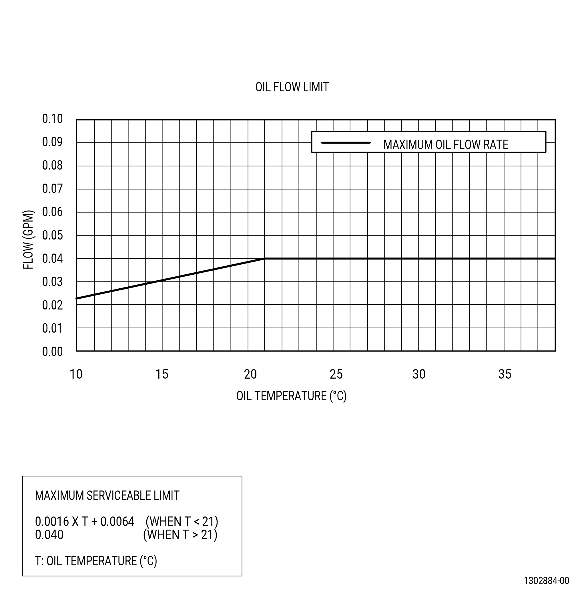
| (4) | Supply C02-023 engine oil to the oil supply port on the No. 5 bearing support housing under the following condition: |
| (a) | Inlet oil temperature: 50° to 100.4°F (10° to 38°C). |
| (b) | Inlet oil pressure: 95-105 psig (655.0-724.0 Kpa gage). |
| (5) | To tap the No. 5 bearing support housing with a nylon mallet is permitted to adjust the piston ring position to stabilize the oil flow. |
| (6) | Make sure that the total oil flow rate is within the limit on the record sheet in the Figure 1008. |
| (7) | Record the oil pressure, oil temperature, and the total oil flow rate on the record sheet in the Figure 1008. |
| (8) | Remove the hydraulic cart from the No. 5 bearing support housing. |
| (9) | Remove the 11C3596 flow check fixture from the No. 5 bearing support housing. |
| (10) | Put protective covers on the No. 5 bearing (01500). |
| (11) | Pull the ball-lock pins (item 7) on the 11C3543 buildup fixture and turn the No. 5 bearing support housing assembly with the forward end pointing up. Install the ball-lock pins (item 7). Refer to Figure 1006. |
| Subtask 72-57-00-440-015 |
| M. | Attach the No. 5 bearing support housing (01-050) (SIN 01501) to the TRF assembly as follows: |
| Subtask 72-57-00-640-002 |
| (1) | Apply the C02-058 lubricant to the threads and washer faces of the bolts (01521) and nuts (01541). |
| NOTE: |
|
| Subtask 72-57-00-440-038 |
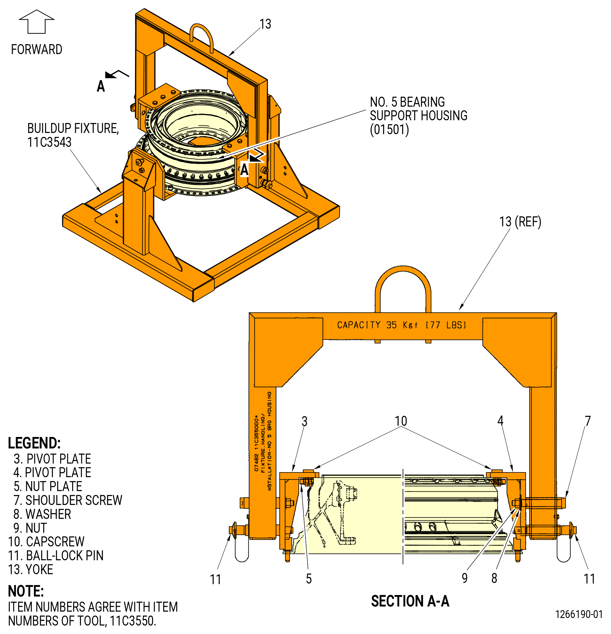
| (2) | Alternative Procedure Available. Install the 11C3550 handling/installation fixture on the No. 5 bearing support housing (01501) as follows. Refer to Figure 1009. |
| (a) | Align the pivot plates (items 3 and 4) in the vertical position and attach with the ball-lock pins (item 11) and the shoulder screw (item 7), washer (item 8), and nut (item 9). |
| NOTE: |
|
| (b) | Attach the overhead hoist to the yoke (item 13). |
| WARNING: |
|
| (c) | Lift the 11C3550 handling/installation fixture and put it over the No. 5 bearing support housing (01501) and lower onto the housing. |
| (d) | Align the locating pins of the pivot plates (items 3 and 4) with the holes of the flange at the 3:00 o'clock and 9:00 o'clock positions. |
| (e) | Attach the No. 5 bearing support housing (01501) to the pivot plates (items 3 and 4) with the capscrews (item 10) and nut plates (item 5). |
| (f) | Remove the nuts (item 28), the lock washers (item 27), the washers (item 26), and the capscrews (item 25) of the 11C3543 buildup fixture from the No. 5 bearing support housing (01501). Refer to Figure 1006. |
| (2).A. | Alternative Procedure. Install the 11C3530 lift fixture to the No. 5 bearing housing (01501). Refer to Subtask 72-57-00-440-005 (paragraph 3.F.). |
| Subtask 72-57-00-440-018 |
| WARNING: |
|
| (3) | Lift the No. 5 bearing support housing (01-050) (SIN 01501) and align in a position above the TRF assembly. Refer to Figure 1010. |
| CAUTION: |
|
| CAUTION: |
|
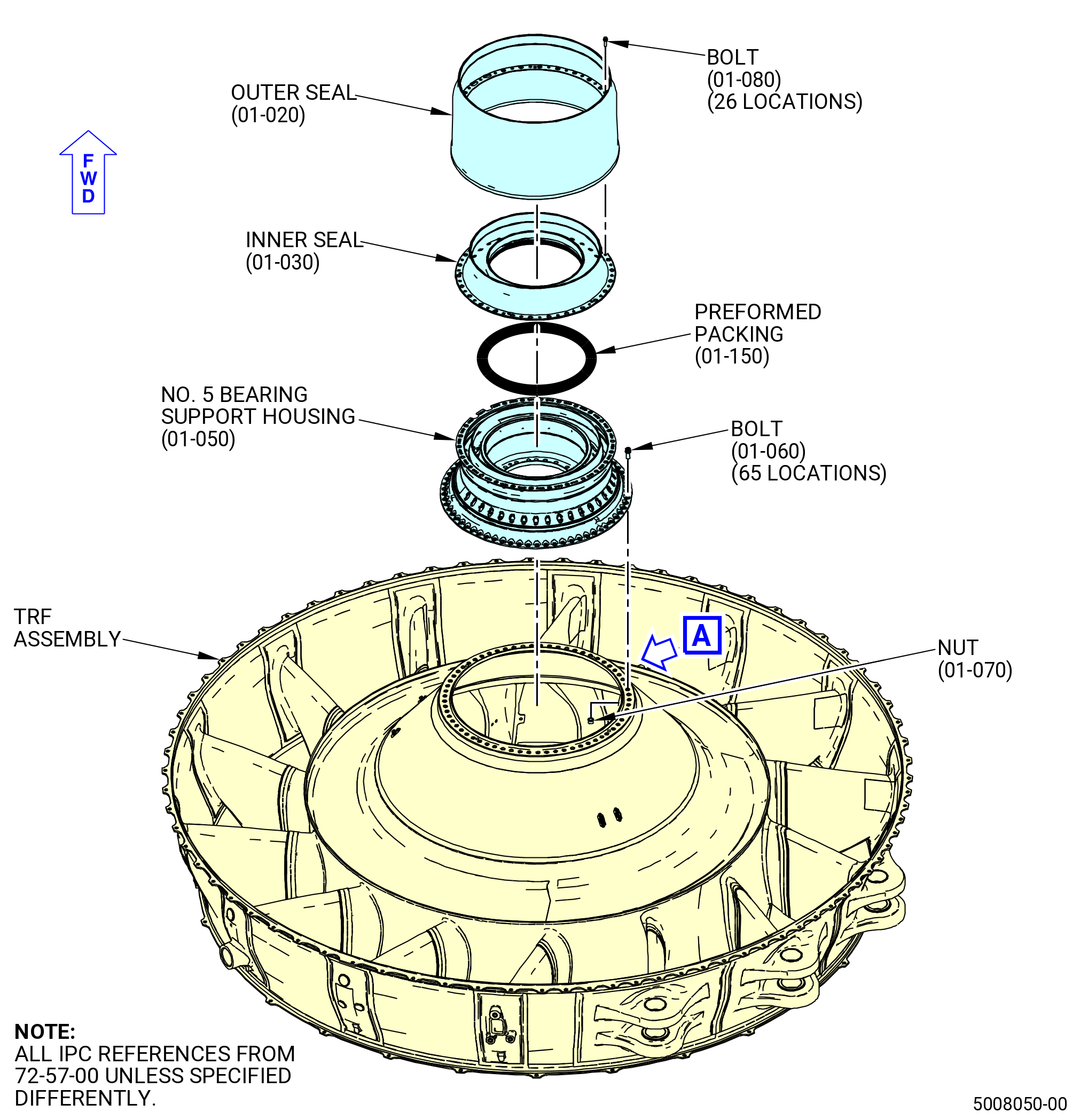
| (4) | Make sure that the aft outer flange of the No. 5 bearing support housing (01-050) (SIN 01501) and the forward inner flange of the TRF assembly are clean and free of raised metal. |
| WARNING: |
|
| (5) | Use a heat gun to increase the temperature of the aft outer flange of the No. 5 bearing support housing for 20 minutes. |
| (6) | Align the top vertical centerline of the No. 5 bearing support housing (01-050) (SIN 01501) with the top vertical centerline of the TRF assembly. Lower the No. 5 bearing support housing to the TRF. |
| (7) | Install the machine bolts (bolts) (01-060) (SIN 01521) through the No. 5 bearing support housing (01-050) (SIN 01501) and the TRF assembly. |
| (8) | Put the self-locking nuts (01541) on every eighth bolt, starting from the top vertical centerline, and counting CW (ALF). Refer to Figure 1010. |
| (9) | Torque the bolts (01521) to 165 lb in. (18.7 N.m) in a criss-cross pattern. |
| Subtask 72-57-00-440-020 |
| (10) | Alternative Procedure Available. Remove the 11C3550 handling/installation fixture from the No. 5 bearing support housing (01501) as follows. Refer to Figure 1009. |
| (a) | Attach the overhead hoist to the yoke (item 13). |
| (b) | Remove the nuts (item 28), the lock washers (item 27), the washers (item 26), and the capscrews (item 25) of the 11C3543 buildup fixture from the No. 5 bearing support housing (01501). Refer to Figure 1006. |
| WARNING: |
|
| (c) | Lift the 11C3550 handling/installation fixture from the No. 5 bearing support housing (01501). |
| (d) | Put the 11C3550 handling/installation fixture in a safe location and remove the overhead hoist. |
| (11) | Alternative Procedure. Remove the 11C3530 lift fixture from the No. 5 bearing housing (01501). Refer to 72-57-00-440-007 (paragraph 3.H.). |
| Subtask 72-57-00-440-021 |
| (12) | Install the remaining self-locking nuts (01541) on the bolts (01521). |
| (13) | Torque all the bolts (01521) at 65 locations to 203-237 lb in. (22.9-26.8 N.m) in a criss-cross pattern. |
| (14) | Torque the bolts (01521) a second time at 65 locations to 203-237 lb in. (22.9-26.8 N.m) in a criss-cross pattern. |
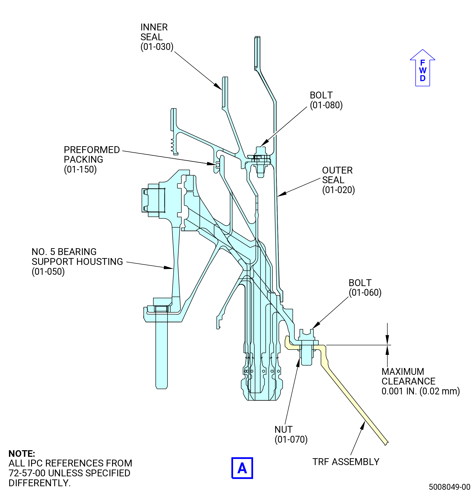
| (15) | Measure the gap between the TRF and the No. 5 bearing support housing with a 0.001 inch (0.02 mm) shim. The shim must not fit. |
| Subtask 72-57-00-220-005 |
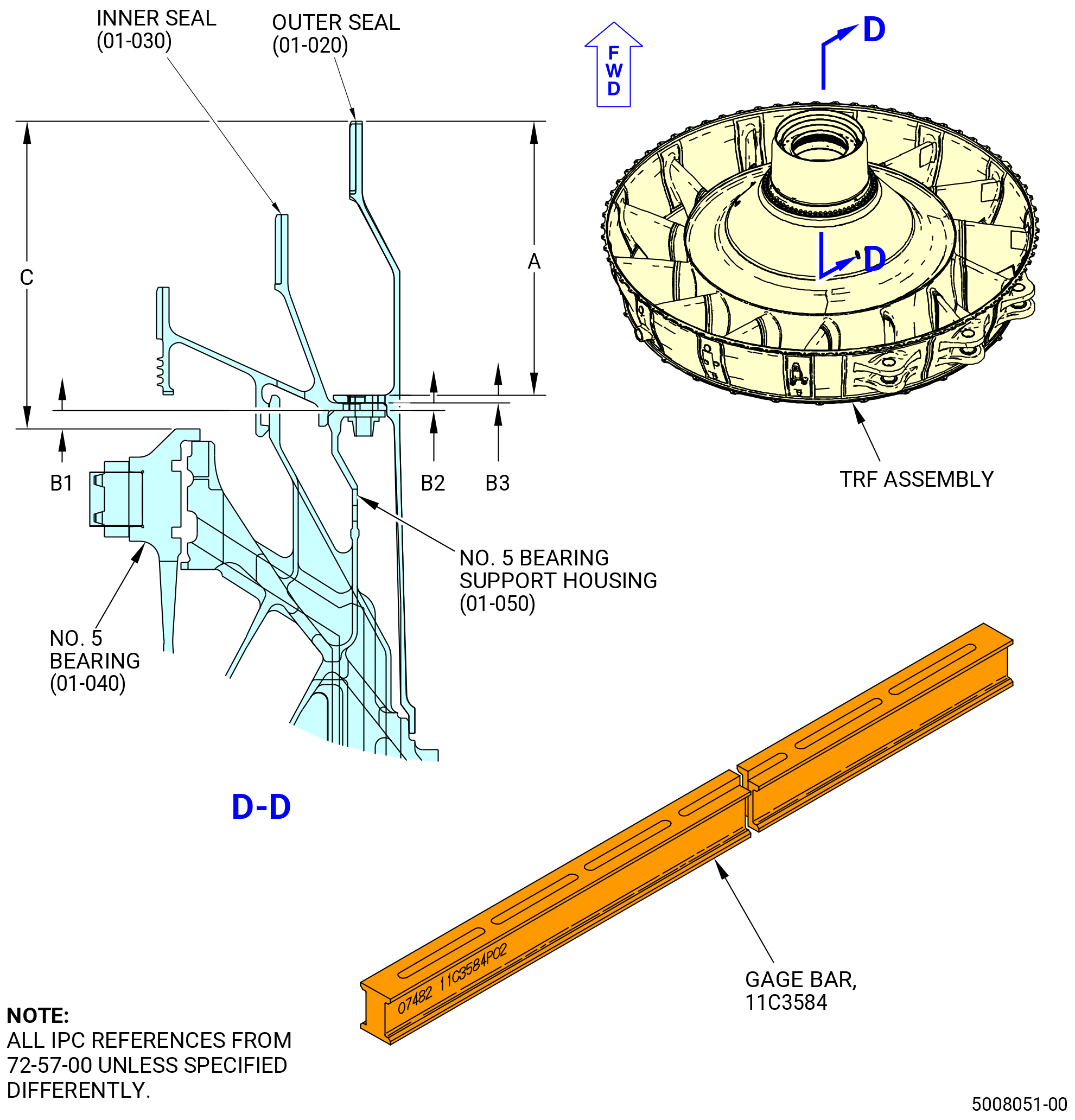
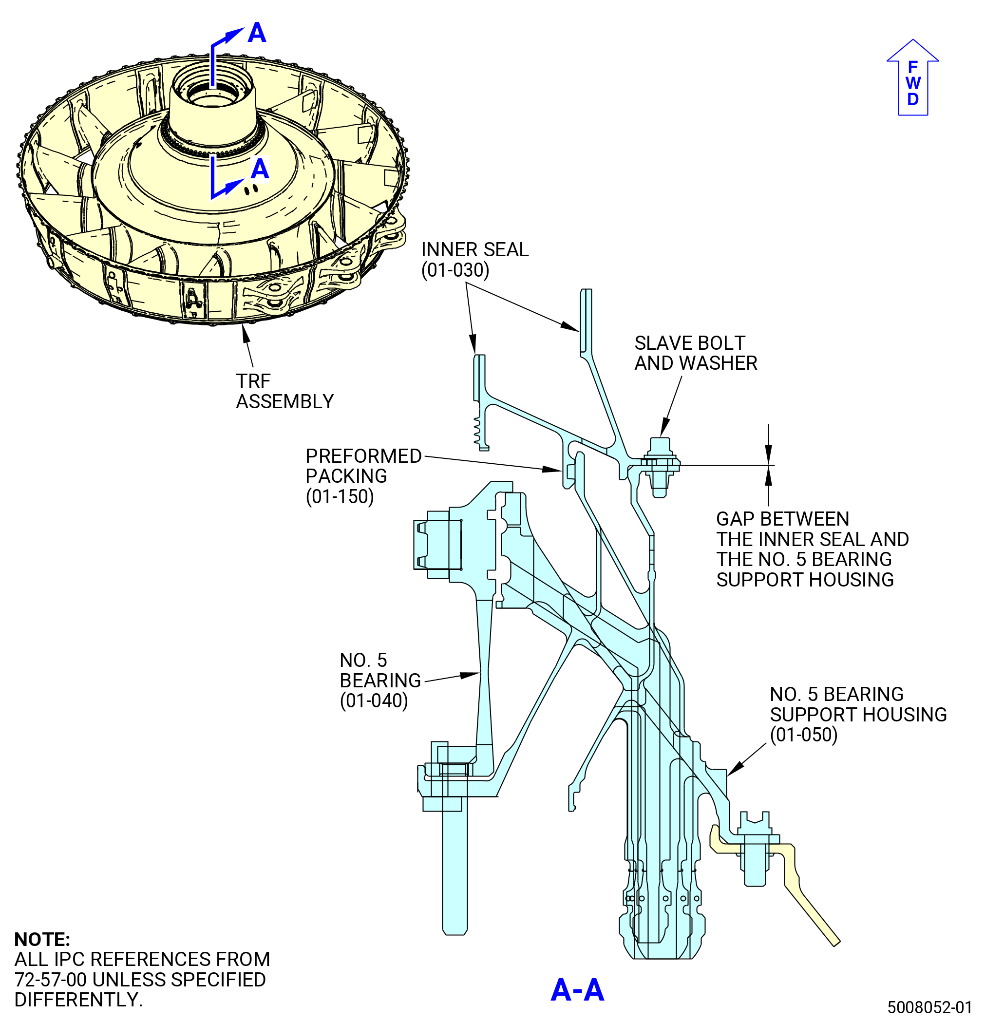
| N. | Measure the No. 5 bearing stationary outer seal (outer seal) (01559), the stationary inner seal (inner seal) (01504), the No. 5 bearing support housing (01501), and the No. 5 bearing (01500) for correct installation as follows. Refer to Figure 1011. |
| NOTE: |
|
| (1) | Measure the distance from the forward end of the No. 5 bearing (01500) to the forward end of the No. 5 bearing support housing (01501) at four equally spaced locations. Record the average as measurement B1. |
| (2) | Measure the thickness of the inner seal (01504) flange at four equally spaced locations. Record the average as measurement B2. |
| (3) | Measure the thickness of the outer seal (01559) flange at four equally spaced locations. Record the average as measurement B3. |
| (4) | Measure the distance of the outer seal (01559) flange to the forward end at four equally spaced locations. Record the average as measurement A. |
| (5) | Total the four dimensions and record as measurement C Calculated (A + B1 + B2 + B3 = C Calculated). |
| Subtask 72-57-00-440-022 |
| O. | Attach the No. 5 bearing stationary inner seal (inner seal) (01504) to the No. 5 bearing support housing (01501) as follows. Refer to Figure 1010 and Figure 1012. |
| Subtask 72-57-00-640-006 |
| (1) | Apply C02-058 lubricant to the threads and washer faces of 13 0.190-32 UNF slave bolts. |
| NOTE: |
|
| Subtask 72-57-00-440-039 |
| CAUTION: |
|
| CAUTION: |
|
| (2) | Make sure that the bolt flange of the inner seal (01504) is clean. |
| Subtask 72-57-00-640-007 |
| WARNING: |
|
| (3) | Apply C02-019 engine oil or C02-023 engine oil to the preformed packing (01-150) (SIN 01552) and the groove in the inner seal (01504). |
| Subtask 72-57-00-440-040 |
| (4) | Install the preformed packing (01-150) (SIN 01552) into the groove of the inner seal (01504). |
| CAUTION: |
|
| (5) | Apply dry ice to the aft flange of the inner seal for 15 minutes. |
| (6) | Make sure that the preformed packing (01-150) (SIN 01552) is in the groove of the inner seal (01504). |
| (7) | Put the inner seal (01504) on the No. 5 bearing support housing (01501). |
| (8) | Install the 13 0.190-32 UNF slave bolts and washers at equally spaced locations. |
| (9) | Torque the slave bolts to 40 lb in. (4.5 N.m) in a criss-cross pattern. |
| (10) | Torque the slave bolts again to 50 to 60 lb in. (5.7 to 6.8 Nm) in a criss-cross pattern. |
| (11) | Make sure that a 0.001 inch (0.02 mm) shim does not enter the gap between the inner seal (01-030) (SIN 01504) and the No. 5 bearing support housing (01-050) (SIN 01501). Refer to Figure 1012. |
| Subtask 72-57-00-440-023 |
| P. | Install the No. 5 bearing stationary outer seal (outer seal) (01559) on the No. 5 bearing support housing (01501) as follows. Refer to Figure 1010. |
| Subtask 72-57-00-640-008 |
| (1) | Apply the C02-058 lubricant to the threads and washer faces of the bolts (01523). |
| NOTE: |
|
| Subtask 72-57-00-440-041 |
| CAUTION: |
|
| CAUTION: |
|
| (2) | Make sure that the flange of the No. 5 bearing support housing (01501) is clean. |
| (3) | Remove the slave bolts and washers that attach the outer seal (01559) to the No. 5 bearing support housing. |
| WARNING: |
|
| (4) | Put the seal housing in an oven and heat to a maximum of 180°F (82°C) for 15 minutes. |
| (5) | Attach the seal housing to the No. 5 bearing support housing with the bolts (01523). |
| (6) | Torque every fifth bolt (01523) to 40 lb in. (4.5 N.m) in a criss-cross pattern. |
| (7) | Torque the bolts (01523) to 50-60 lb in. (5.7-6.8 N.m) in a criss-cross pattern. |
| (8) | Torque the bolts (01523) a second time to 50-60 lb in. (5.7-6.8 N.m) in a criss-cross pattern. |
| Subtask 72-57-00-220-006 |
| (9) | Measure the distance from the forward end of the outer seal (01559) to the forward surface of the No. 5 bearing (01500). Record as measurement C Actual. Refer to Figure 1011. |
| (a) | The measurement C Calculated and the measurement C Actual must be plus or minus 0.0015 inch (0.038 mm). |
| Subtask 72-57-00-440-024 |
| Q. | Turn the TRF assembly in the 9429M60 assembly stand to the horizontal position, forward end down. Refer to Figure 1004 and do as follows: |
| CAUTION: |
|
| CAUTION: |
|
| (1) | Lower the floor locks (item 69) of the 9429M60 assembly stand until they touch the floor. The floor locks must stay in contact with the floor to prevent movement of the roll-over stand. Make sure that the roll-over stand is level. |
| (2) | Push the lever (item 24) to unlock the hand wheel (item 31). |
| (3) | Turn the hand wheel (item 31) until the TRF is in the vertical position, forward end down. |
| CAUTION: |
|
| (4) | Pull the lever (item 24) to engage the locating pin into the locating plate (item 6) and to lock the hand wheel (item 31). |
| Subtask 72-57-00-440-025 |
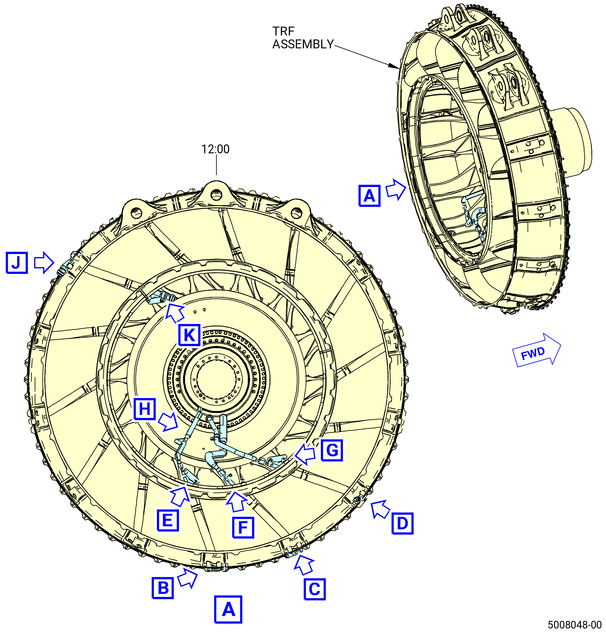
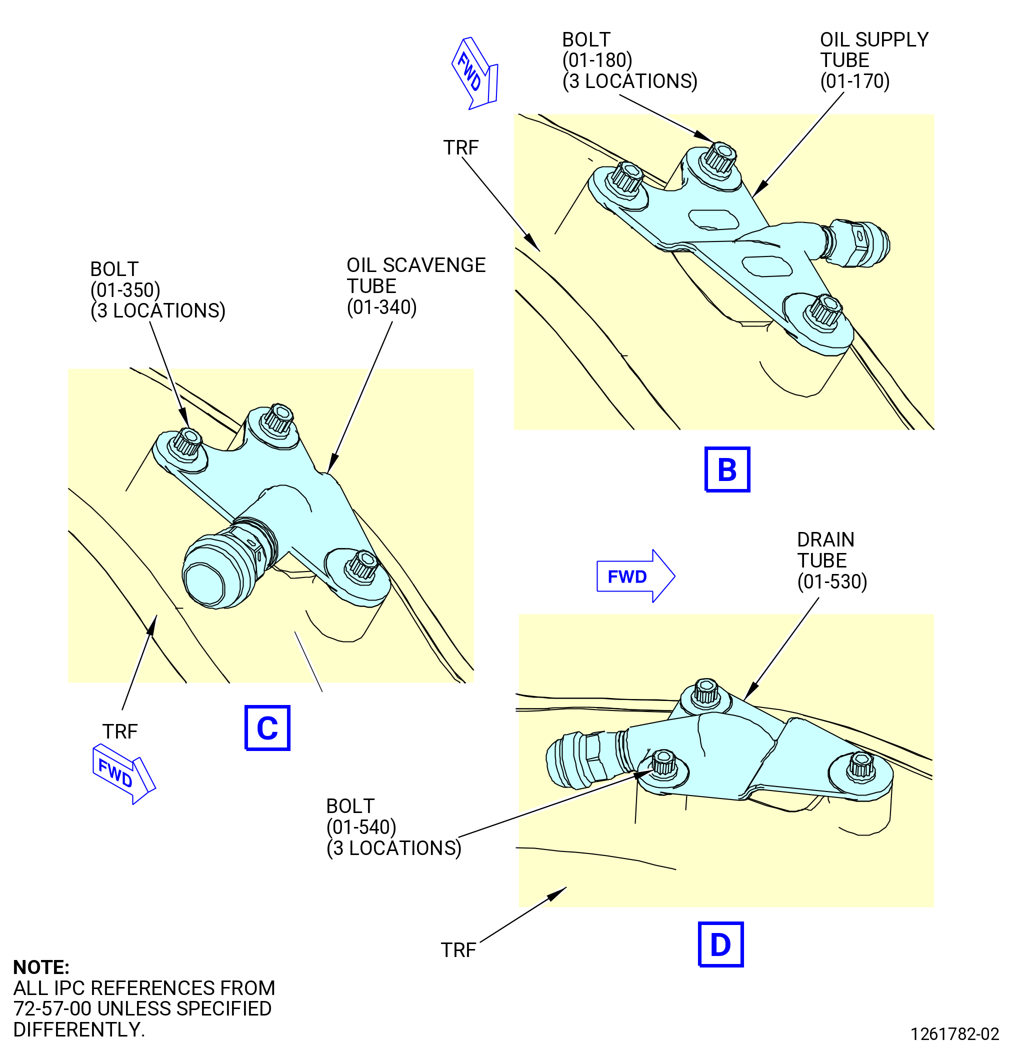
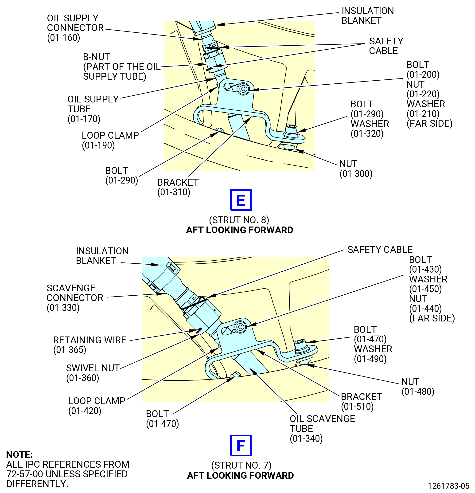
| R. | Install the scavenge assembly tube (oil scavenge tube) (01-340) (SIN 452A1) into strut No. 7 of the TRF assembly. Refer to Figure 1013 and do as follows: |
| (1) | Install the oil scavenge tube (452A1) into strut No. 7 of the TRF. |
| (2) | Make sure to keep a minimum clearance of 0.039 inch (1.00 mm) between the oil scavenge tube (01-340) (SIN 452A1) and strut No. 7 walls of the TRF. |
| Subtask 72-57-00-640-009 |
| (3) | Apply C02-058 lubricant to the threads and washer faces of the bolts (452F0, 452F1, 452F2), and the mating surfaces of the washers (452J0, 452J1) and the nuts (452K0, 452K1). |
| Subtask 72-57-00-440-042 |
| (4) | Loosely attach the oil scavenge tube to the TRF assembly outer ring with the bolts (01-350) (SIN 452F0) at three locations. |
| (5) | Loosely attach the bracket (01-510) (SIN 452E1) to the inner frame of the TRF with the bolt (01-470) (SIN 452F1), washer (01-490) (SIN 452J0), and nut (01-480) (SIN 452K0). Put the washer between the bolt and the bracket. |
| (6) | Loosely attach the bracket to the inner frame of the TRF assembly with the bolts (01-470) (SIN 452F1) at two locations. |
| (7) | Install the loop clamp (452V0) on the oil scavenge tube. |
| (8) | Loosely attach the loop clamp (01-420) (SIN 452V0) to the bracket (01-510) (SIN 452E1) with a bolt (01-430) (SIN 452F2), washers (01-450) (SIN 452J1), and nut (01-440) (SIN 452K1). |
| (9) | Do not torque the bolts (01-350) (SIN 452F0), bolt (01-430) (SIN 452F2), bolts (01-470) (SIN 452F1), and the nut (01-480) (SIN 452K0) at this time. |
| Subtask 72-57-00-440-047 |
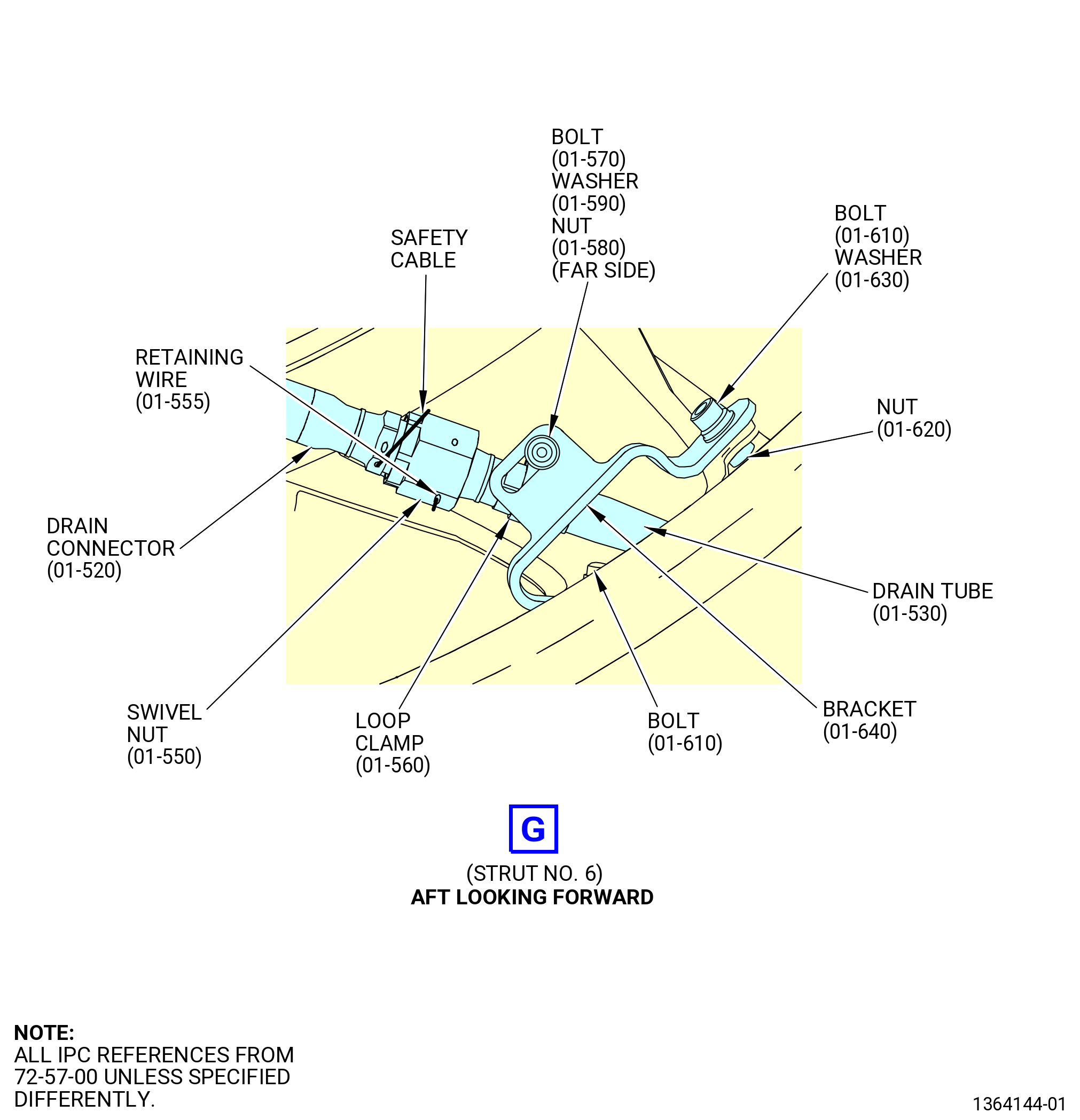
| S. | Install the drain tube (01-530) (SIN 458A1) in the TRF assembly at strut No. 6. Refer to Figure 1013 and do as follows: |
| (1) | Put the drain tube (01-530) (SIN 458A1) into the TRF assembly at strut No. 6 from the outward flange. |
| (2) | Make sure to keep a minimum clearance of 0.039 inch (1.00 mm) between the drain tube (01-530) (SIN 458A1) and strut No. 6 walls of the TRF. |
| Subtask 72-57-00-640-012 |
| (3) | Apply C02-058 lubricant to the threads and washer faces of the bolts (458F0, 458F1, 458F2), and the mating surfaces of the washers (458J0, 458J1) and the nuts (458K0, 458K1). |
| Subtask 72-57-00-440-048 |
| (4) | Loosely attach the drain tube (01-530) (SIN 458A1) to the TRF frame with the bolts (01-540) (SIN 458F0) at three locations. |
| (5) | Loosely attach the bracket (01-640) (SIN 458E0) to the inner frame of the TRF with bolts (01-610) (SIN 458F1), washer (01-630) (SIN 458J0), and nut (01-620) (SIN 458K0). Put the washer between the bolt and the bracket. |
| (6) | Loosely attach the bracket to the inner frame of the TRF assembly with the bolts (01-610) (SIN 458F1) at two locations. |
| (7) | Install the loop clamp (458V0) on the drain tube (458A1). |
| (8) | Loosely attach the loop clamp (01-560) (SIN 458V0) to the bracket (01-640) (SIN 458E0) with a bolt (01-570) (SIN 458F2), washers (01-590) (SIN 458J1), and nut (01-580) (SIN 458K1). Put the washers between the bolt and bracket, and between the clamp and nut. |
| (9) | Do not torque the bolts (01-540) (SIN 458F0), bolt (01-570) (SIN 458F2), bolts (01-610) (SIN 458F1), and the nut (01-620) (SIN 458K0) at this time. |
| Subtask 72-57-00-440-049 |
| T. | Install the oil supply tube (01-170) (SIN 443A1) in the TRF assembly at strut No. 8. Refer to Figure 1013 and do as follows: |
| (1) | Put the oil supply tube (01-170) (SIN 443A1) into the TRF assembly at strut No. 8 from the outward flange. |
| (2) | Make sure to keep a minimum clearance of 0.039 inch (1.00 mm) between the oil supply tube (01-170) (SIN 443A1) and strut No. 8 walls of the TRF. |
| Subtask 72-57-00-640-013 |
| (3) | Apply C02-058 lubricant to the threads and washer faces of the bolts (443F0, 443F1, 443F2), and the mating surfaces of the washers (443J0, 443J1) and the nuts (443K0, 443K1). |
| Subtask 72-57-00-440-050 |
| (4) | Loosely attach the oil supply tube (01-170) (SIN 443A1) to the TRF outer case with the bolts (01-180) (SIN 443F0). |
| (5) | Loosely attach the bracket (01-310) (SIN 443E1) to the inner frame of the TRF with the bolt (01-290) (SIN 443F1), washer (01-320) (SIN 443J0), and nut (01-300) (SIN 443K0). Put the washer between the bolt and the bracket. |
| (6) | Loosely attach the bracket to the inner frame of the TRF assembly with the bolt (01-290) (SIN 443F1) at two locations. |
| (7) | Install the loop clamp (443V0) on the oil supply tube (443A1). |
| (8) | Attach the loop clamp (443V0) to the bracket (443E1) with a bolt (443F2), washers (443J1), and nut (443K2). Put a washer under the bolt and the nut. |
| (9) | Do not torque the bolts (01-180) (SIN 443F0), bolt (01-200) (SIN 443F2), bolts (01-290) (SIN 443F1), and the nut (01-300) (SIN 443K0) at this time. |
| Subtask 72-57-00-440-045 |
| U. | Turn the TRF assembly in the 9429M60 assembly stand to the vertical position, top vertical centerline up. Refer to Figure 1004 and do as follows: |
| CAUTION: |
|
| CAUTION: |
|
| (1) | Lower the floor locks (item 69) of the 9429M60 assembly stand until they touch the floor. The floor locks must stay in contact with the floor to prevent movement of the roll-over stand. Make sure that the roll-over stand is level. |
| (2) | Push the lever (item 24) to unlock the hand wheel (item 31). |
| (3) | Turn the hand wheel (item 31) until the TRF is in the horizontal position, top vertical centerline up. |
| CAUTION: |
|
| (4) | Pull the lever (item 24) to engage the locating pin into the locating plate (item 6) and to lock the hand wheel (item 31). |
| Subtask 72-57-00-440-027 |
| V. | Install the connector scavenge assembly tube (scavenge connector) (01-330) (SIN 452A0), the connector drain assembly tube (drain connector) (01-520) (SIN 458A0), and the connector supply 1 assembly tube (oil supply connector) (01-160) (SIN 443A0). |
| (1) | Put the swivel nut (01-360) (SIN 45240) on the lower end of the scavenge connector. |
| (2) | Loosely attach the upper end of the scavenge connector to the right fitting on the No. 5 bearing support housing at the 6:00 o'clock position. |
| (3) | Loosely attach the lower end of the scavenge connector to the oil scavenge tube (01-340) (SIN 452A1) with the swivel nut (01-360) (SIN 45240) at the strut No. 7. |
| (4) | Install the retaining wire (01-365) (SIN 45298) in the swivel nut (01-360) (SIN 45240) when the circumferential grooves on the scavenge connector end and the swivel nut are aligned. |
| (5) | Put the swivel nut (01-550) (SIN 45840) on the lower end of the drain connector. |
| (6) | Loosely attach the upper end of the drain connector to the central fitting on the No. 5 bearing support housing at the 6:00 o'clock position. |
| (7) | Loosely attach the lower end of the drain connector to the drain tube (01-530) (SIN 458A1) with the swivel nut (01-550) (SIN 45840) at the strut No. 6. |
| (8) | Install the retaining wire (01-555) (SIN 45898) in the swivel nut (01-550) (SIN 45840) when the circumferential grooves on the drain connector end and swivel nut are aligned. |
| (9) | Loosely attach the upper end of the supply connector to the left fitting on the No. 5 bearing support housing at the 6:00 o'clock position. |
| (10) | Loosely attach the lower end of the oil supply connector to the oil supply tube (01-170) (SIN 443A1) at the strut No. 8. |
| (11) | Loosely attach the bracket (01-280) (SIN 443E0) to the TRF with bolts (01-290) (SIN 443F1). |
| (12) | Loosely attach the bracket (01-500) (SIN 452E0) to the TRF with two bolts (01-470) (SIN 452F1). |
| (13) | Loosely attach the oil supply connector to the bracket (01-280) (SIN 443E0), the drain connector, and the scavenge connector to the bracket (01-500) (SIN 452E0) as follows: |
| (a) | Install the loop clamp (01-190) (SIN 443V0) on the oil supply connector. |
| (b) | Install the clamps (01-600) (SIN 458V1) and (01-460) (SIN 452V1) on the scavenge connector and the drain connector tubes. |
| (c) | Loosely attach the clamp (01-190) (SIN 443V0) to the bracket (01-280) (SIN 443E0) with the bolts (01-290) (SIN 443F1) and nut (01-300) (SIN 443K0). |
| (d) | Loosely attach the clamp (01-600) (SIN 458V1) to the bracket (01-500) (SIN 452E0) with the bolt (01-610) (SIN 458F1), washer (01-630) (SIN 458J0), and nut (01-620) (SIN 458K0). Put the washer between the bolt and the bracket. |
| (e) | Loosely attach the clamp (01-460) (SIN 452V1) to the bracket (01-500) (SIN 452E0) with the bolt (01-470) (SIN 452F1), washer (01-490) (SIN 452J0), and nut (01-480) (SIN 452K0). Put the washer between the bolt and the bracket. |
| (14) | Make sure to keep a minimum clearance of 0.039 inch (1.00 mm) between the tubes installed in the struts and the strut walls. |
| (15) | Make sure to keep a minimum clearance of 0.125 inch (3.18 mm) between the connector tubes or the tube insulations to the adjacent parts. |
| (16) | Hand-tighten the bolts in the TRF outer ring at the struts No. 6, No. 7, and No. 8. |
| (17) | Torque the connector tube B-nuts to the fittings on the No. 5 bearing support housing at the 6:00 o'clock position as follows: |
| CAUTION: |
|
| (a) | Torque the scavenge connector (01-330) (SIN 452A0) B-nut (right fitting, ALF) as follows: |
| 1 | Torque the B-nut to 79 to 91 lb ft (108.0 to 123.0 Nm). |
| 2 | Loose the B-nut and torque again to 79 to 91 lb ft (108.0 to 123.0 Nm). |
| 3 | Apply a final torque of 79 to 91 lb ft (108.0 to 123.0 Nm). |
| (b) | Torque the drain connector (01-520) (SIN 458A0) B-nut (central fitting, ALF) as follows: |
| 1 | Torque the B-nut to 79 to 91 lb ft (108.0 to 123.0 Nm). |
| 2 | Loosen the B-nut and torque again to 79 to 91 lb ft (108.0 to 123.0 Nm). |
| 3 | Apply a final torque of 79 to 91 lb ft (108.0 to 123.0 Nm) to the B-nut. |
| (c) | Torque the oil supply connector (01-160) (SIN 443A0) B-nut (left fitting, ALF) as follows: |
| 1 | Torque the B-nut to 263 to 307 lb in. (30.0 to 34.0 Nm). |
| 2 | Loose the B-nut and torque again to 263 to 307 lb in. (30.0 to 34.0 Nm). |
| 3 | Apply a final torque of 263 to 307 lb in. (30.0 to 34.0 Nm) to the B-nut. |
| (18) | Torque the connector tube B-nuts and the swivel nuts to the oil tubes at the struts No. 6, No. 7, and No. 8 as follows: |
| CAUTION: |
|
| (a) | Torque the swivel nut of the scavenge connector to the oil scavenge tube at the strut No. 7 as follows: |
| 1 | Torque the swivel nut to 56 to 64 lb ft (76.0 to 86.0 Nm). |
| 2 | Loose the swivel nut and torque again to 56 to 64 lb ft (76.0 to 86.0 Nm). |
| 3 | Apply a final torque of 56 to 64 lb ft (76.0 to 86.0 Nm) to the swivel nut. |
| (b) | Torque the swivel nut of the drain connector to the drain tube at the strut No. 6 as follows: |
| 1 | Torque the swivel nut to 56 to 64 lb ft (76.0 to 86.0 Nm). |
| 2 | Loosen the swivel nut and torque again to 56 to 64 lb ft (76.0 to 86.0 Nm). |
| 3 | Apply a final torque of 56 to 64 lb ft (76.0 to 86.0 Nm) to the swivel nut. |
| (c) | Torque the B-nut of the oil supply connector to the oil supply tube at the strut No. 8 as follows: |
| 1 | Torque the B-nut to 263 to 307 lb in. (30.0 to 34.0 Nm). |
| 2 | Loose the B-nut and torque again to 263 to 307 lb in. (30.0 to 34.0 Nm). |
| 3 | Apply a final torque of 263 to 307 lb in. (30.0 to 34.0 Nm) to the B-nut. |
| (d) | Make sure to keep a minimum clearance of 0.039 inch (1.00 mm) between the tube installed in the struts and the strut walls, and a minimum clearance of 0.125 inch (3.18 mm) between the connector tubes or the tube insulation to the adjacent parts. |
| (e) | Safety all the B-nuts and swivel nuts with C10-071 safety wire or C10-143 safety cable assembly. |
| (19) | Torque the bolts that attach the drain tube (01-530) (SIN 458A1), oil scavenge tube (01-340) (SIN 452A1), and the oil supply tube (01-170) (SIN 443A1) at the pads of the struts No. 6, No. 7, and No. 8 on the TRF assembly outer frame to 58-66 lb in. (6.6-7.5 N.m). |
| (20) | Torque the nuts and bolts that attach the brackets (01-640) (SIN 458E0), (01-510) (SIN 452E1), and (01-310) (SIN 443E1) at the struts No. 6, No. 7, and No. 8 on the inner frame of the TRF assembly to 58-66 lb in. (6.6-7.5 N.m). |
| (21) | Torque the nuts that attach the tubes at the struts No. 6, No. 7, and No. 8 to the brackets (01-640) (SIN 458E0), (01-510) (SIN 452E1), and (01-310) (SIN 443E1) to 33-37 lb in. (3.7-4.2 N.m). |
| (22) | Torque the bolts (01-290) (SIN 443F1) that attach the bracket (01-280) (SIN 443E0) to the TRF to 58-66 lb in. (6.6-7.5 N.m). |
| (23) | Torque the bolts (01-470) (SIN 452F1) that attach the bracket (01-500) (SIN 452E0) to the TRF to 58-66 lb in. (6.6-7.5 N.m). |
| (24) | Torque the nut that attach the oil supply connector (01-160) (SIN 443A0) to the bracket (01-280) (SIN 443E0) to 58-66 lb in. (6.6-7.5 N.m). |
| (25) | Torque the nuts that attach the scavenge connector (01-330) (SIN 452A0) and the drain connector (01-520) (SIN 458A0) to the bracket (01-500) (SIN 452E0) to 58-66 lb in. (6.6-7.5 N.m). |
| (26) | Make sure that to keep a minimum clearance of 0.039 inch (1.00 mm) between the tubes installed in the struts and the strut walls, and a minimum clearance of 0.125 inch (3.18 mm) between the connector tubes or the tube insulations to the adjacent parts. |
| Subtask 72-57-00-440-053 |
| W. | Deleted. |
| Subtask 72-57-00-640-017 |
| (1) | Deleted. |
| Subtask 72-57-00-640-020 |
| (2) | Deleted. |
| Subtask 72-57-00-440-054 |
| (3) | Deleted. |
| Subtask 72-57-00-440-057 |
| (4) | Deleted. |
| Subtask 72-57-00-790-001 |
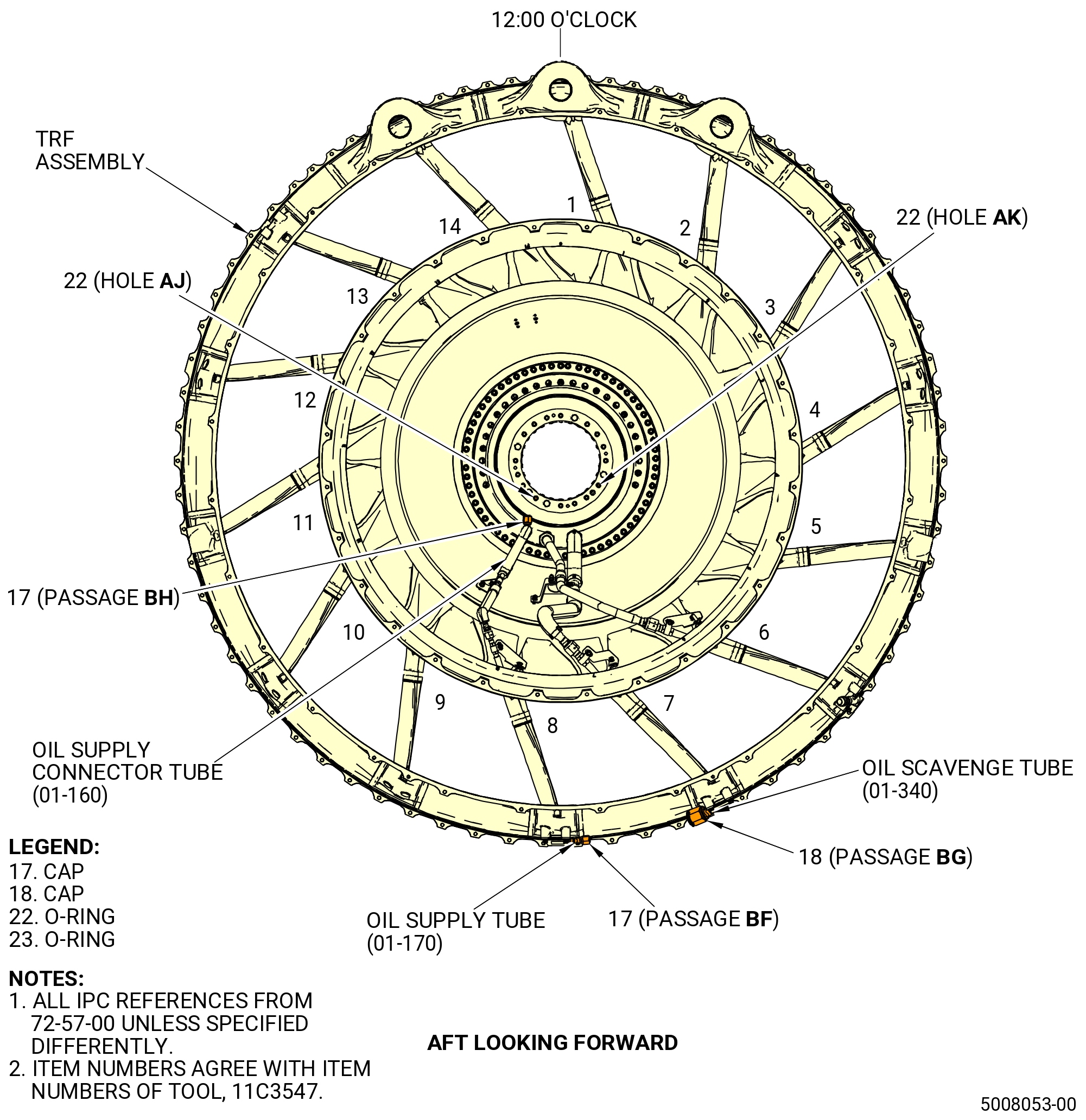
| X. | Do a leak check of the No. 5 bearing support housing (01501), the oil supply tube (443A1), and the oil scavenge tube (452A1). Use the 11C3547 closure set as follows. Refer to Figure 1013 and Figure 1014. |
| (1) | Install a cap (item 17) of the 11C3547 closure set on the oil supply connector tube (443A0) (passage BH). Tighten the cap. |
| (2) | Install a cap (item 17) of the 11C3547 closure set on the outboard end of the oil supply tube (01-170) (SIN 443A1) at strut No. 8 (passage BF) of the TRF assembly. Tighten the cap. |
| (3) | Install a cap (item 18) of the 11C3547 closure set on the outboard end of the oil scavenge tube (01-340) (SIN 452A1) at strut No. 7 (passage BG) of the TRF assembly. Tighten the cap. |
| Subtask 72-57-00-640-018 |
| WARNING: |
|
| (4) | Apply a thin coating of C02-019 engine oil or C02-023 engine oil on the O-rings (items 22 and 23). |
| WARNING: |
|
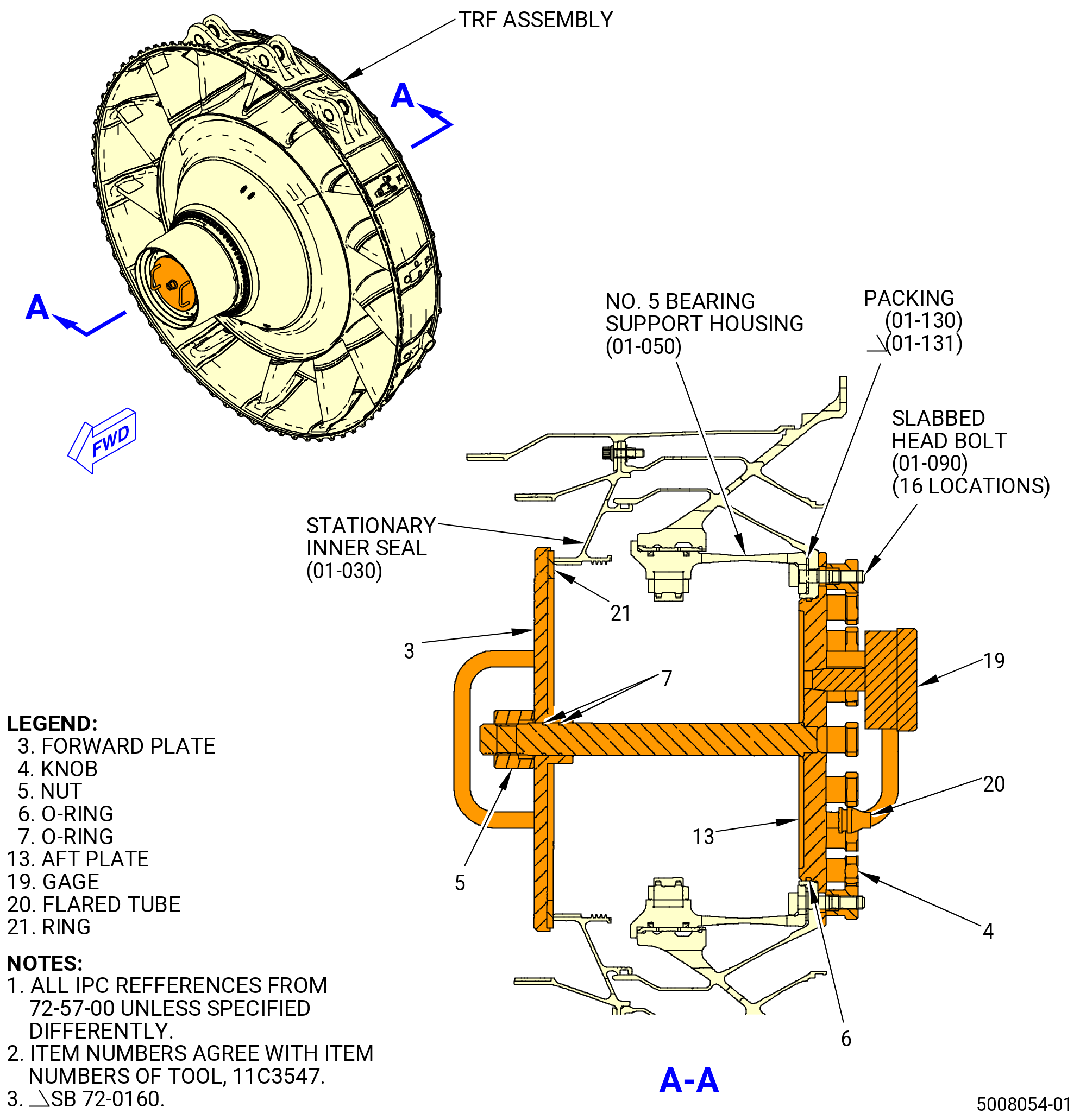
| (5) | Apply a thin coating of C02-019 engine oil or C02-023 engine oil on the O-rings (item 7) at two locations. The O-rings (item 7) are installed on the shaft of the aft plate (item 13). |
| WARNING: |
|
| (6) | Apply a thin coating of C02-019 engine oil or C02-023 engine oil on the O-ring (item 6) on the aft plate (item 13). |
| WARNING: |
|
| (7) | Apply a thin coating of C02-019 engine oil or C02-023 engine oil on the ring (item 21) on the forward plate (item 3). |
| Subtask 72-57-00-790-002 |
| (8) | Install an O-ring (item 22) in Hole AJ. |
| (9) | Install an O-ring (item 23) in Hole AK. |
| (10) | Put the aft plate (item 13) in position against the aft side of the No. 5 bearing support housing (01-050) (SIN 01501) on the packing (01-130) (SIN 01556) or (01-131) (SIN 01556) with the shaft of the aft plate through the housing. Align the word TOP on the aft plate with the 12:00 o'clock position and the four cutouts of the aft plate with the bolts (01-110) (SIN 01528). Hold the aft plate in position. |
| (11) | Install the knobs (item 4) on the slabbed head bolts (01522) at 16 locations. Torque the knobs to 240 lb in. (27.1 N.m). |
| (12) | Put the forward plate (item 13) in position against the forward side of the stationary inner seal (01504). Make sure that the ring (item 21) is on the stationary inner seal. |
| (13) | Install the nut (item 5) on the shaft of the aft plate (item 13). Tighten the nut hand-tight, then use a wrench and tighten the nut 270 degrees (three-quarter turn). |
| (14) | If necessary, install a calibrated gage (item 19) to the aft plate (item 13). |
| WARNING: |
|
| (15) | Connect an air hose with a regulated air supply to the flared tube (item 20). |
| (16) | Increase the pressure until the gage (item 19) shows 15-20 psig (103-138 kPa gage). |
| (17) | Turn off the air supply. |
| (18) | Monitor the gage (item 19) for a minimum of five minutes and look for a decrease in pressure. The maximum rate of pressure leakage is 3.0 psig (20.7 kPa gage). |
| (19) | If the pressure decreases more that 3.0 psig (20.7 kPa gage) in five minutes, do an inspection to find the source of the leakage. |
| (20) | Bleed off the pressure until the gage (item 8) shows 0 psig (0 kPa gage). |
| (21) | Disconnect the air hose from the flared tube (item 20). |
| (22) | Remove the caps (item 17 and 18) from the tubes outboard of struts No. 7 and 8 (passage BF and BG). |
| (23) | Remove the cap (item 17) from the oil supply connector tube (443A0) (passage BH) on the No. 5 bearing support housing (01501). |
| Subtask 72-57-00-440-056 |
| (24) | Remove the 11C3547 closure set from the No. 5 bearing support housing (01501) and the stationary inner seal (01504) as follows: |
| (a) | Remove the nut (item 5) from the shaft of the aft plate (item 13). |
| (b) | Remove the forward plate (item 3) from the stationary inner seal. |
| (c) | Remove the knobs (item 4) from the slabbed head bolts (01522) on the aft plate (item 13). |
| (d) | Remove the aft plate (item 5) from the aft side of the No. 5 bearing support housing. |
| Subtask 72-57-00-220-002 |
| Y. | Do a visual inspection of the TRF assembly for possible damage, loose or missing parts, or unwanted material. |
| Subtask 72-57-00-440-031 |
| CAUTION: |
|
| CAUTION: |
|
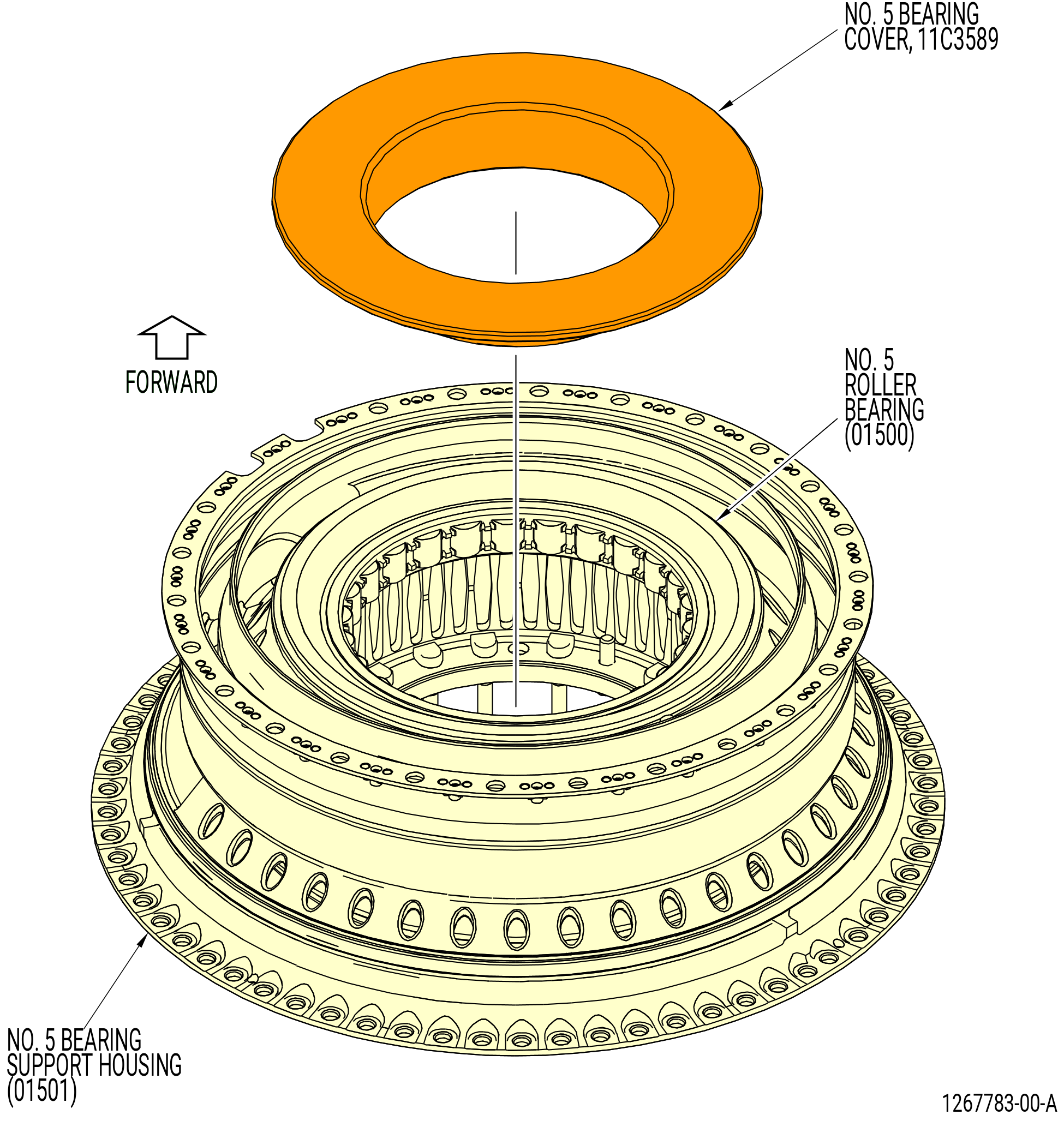
| Z. | Install the 11C3589 No. 5 bearing cover on the No. 5 Roller Bearing. Refer to Figure 1015. |
| Subtask 72-57-00-440-032 |
| AA. | Install covers/plugs on all the open ports. |
| Subtask 72-57-00-440-033 |
| WARNING: |
|
| AB. | Remove all the unwanted C02-058 lubricant from the TRF assembly. |
| Subtask 72-57-00-440-034 |
| AC. | Attach the 11C4293 TRF flow path protector to the aft end of the TRF assembly. Refer to Figure 1016. |
| AD. | Continue to install the TRF assembly. Refer to TASK 72-00-04-430-801 (72-00-04, ASSEMBLY 001, CONFIG 01) or TASK 72-00-04-430-802 (72-00-04, ASSEMBLY 001, CONFIG 02). |