| GENX-1B ENGINE MANUAL | Dated: 06/14/2021 | |
| EM 72-56-00 , ASSEMBLY 001 | ||
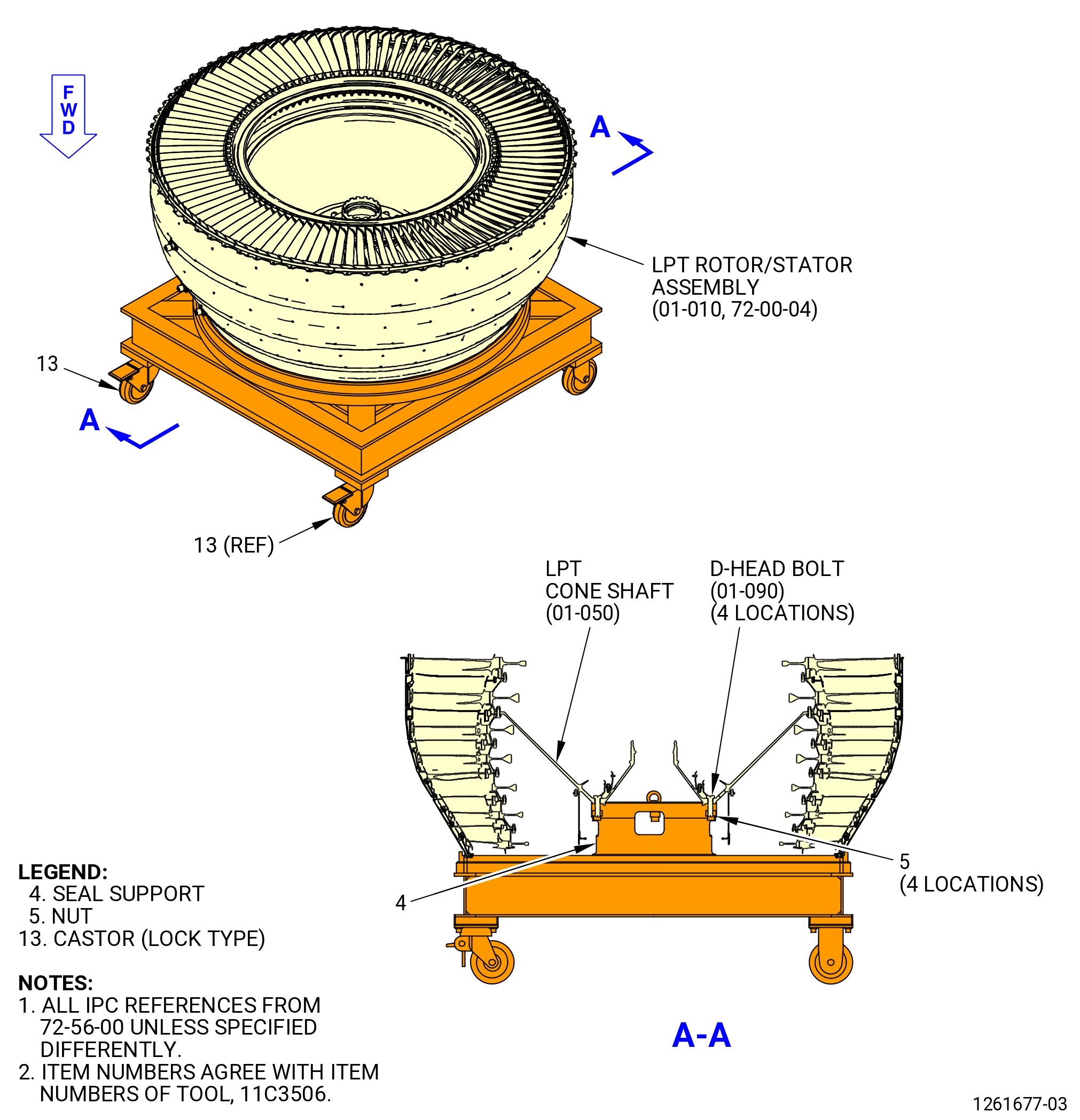
| LOW PRESSURE TURBINE ROTOR/STATOR ASSEMBLY - ASSEMBLY 001 CONFIGURATION 01 | ||
| GENX-1B ENGINE MANUAL | Dated: 06/14/2021 | |
| EM 72-56-00 , ASSEMBLY 001 | ||
| LOW PRESSURE TURBINE ROTOR/STATOR ASSEMBLY - ASSEMBLY 001 CONFIGURATION 01 | ||
| * * * FOR 1B/P/G03 |
| TASK 72-56-00-440-801 |
| 1 . | General. |
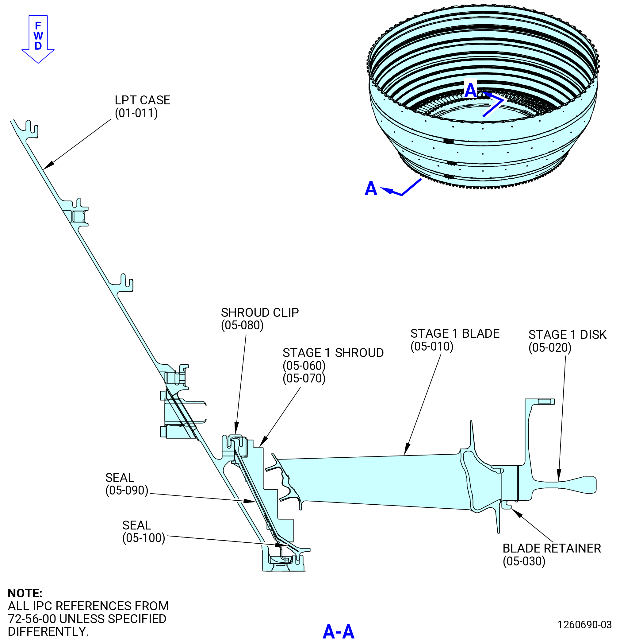
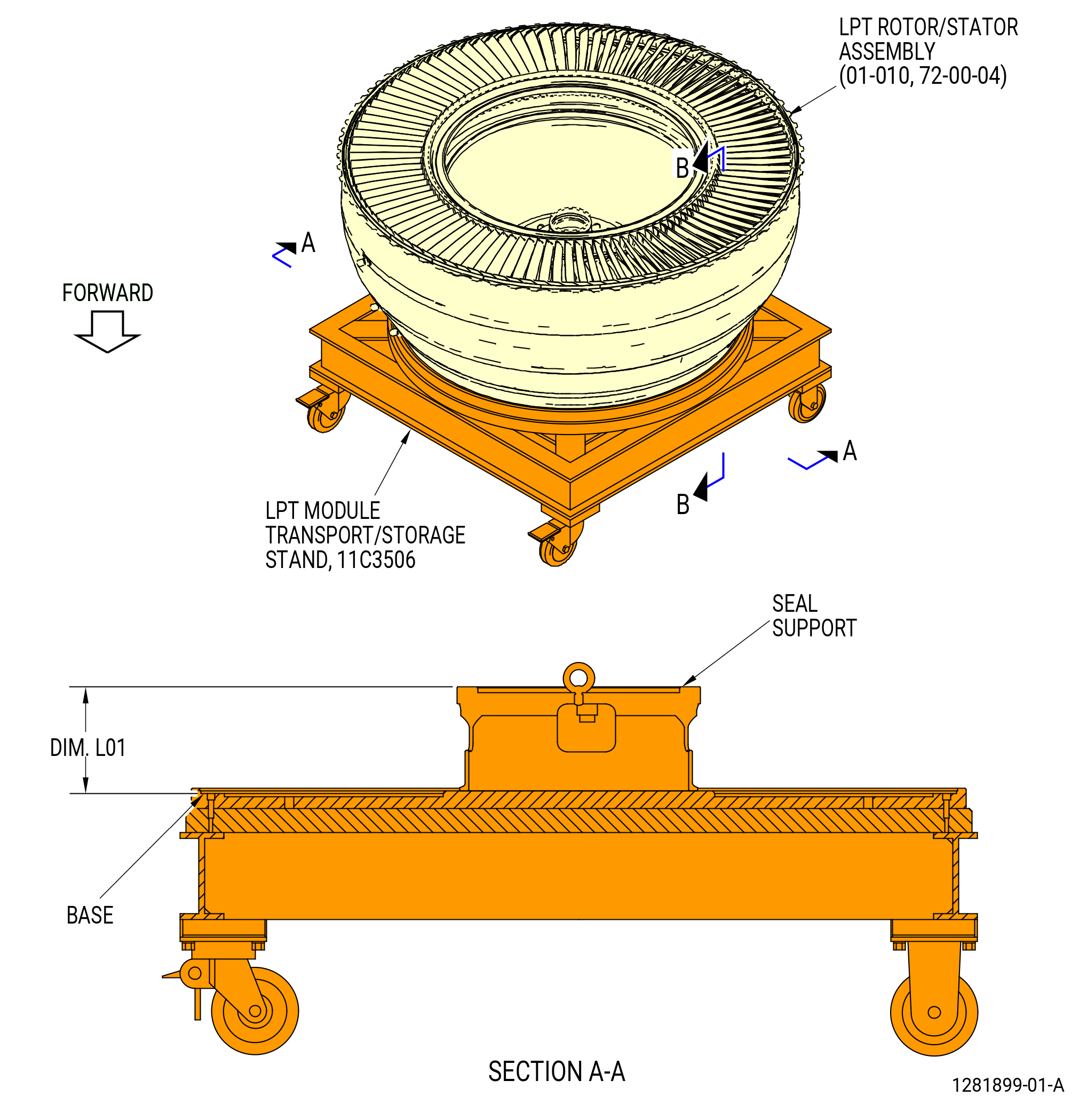
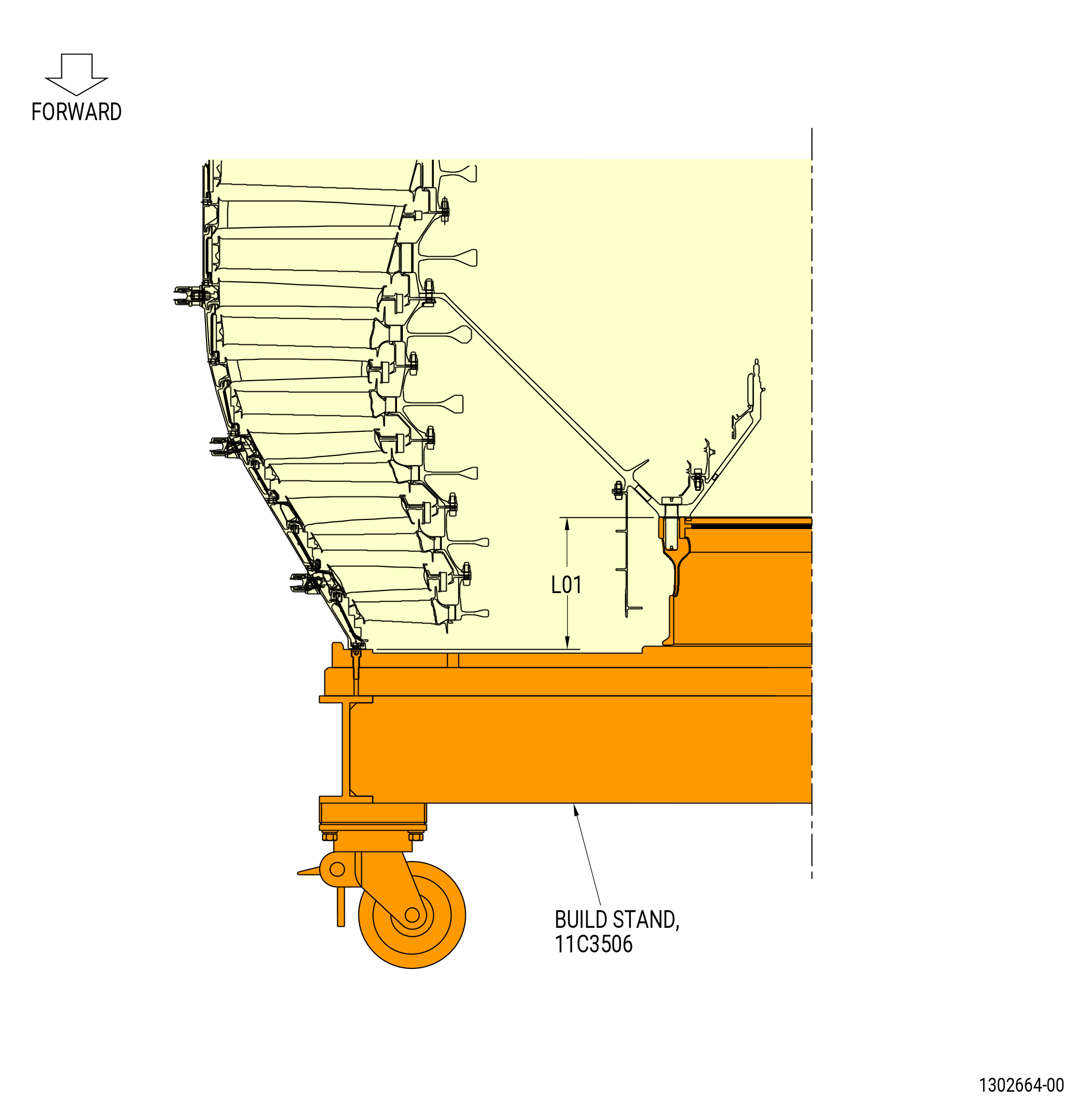
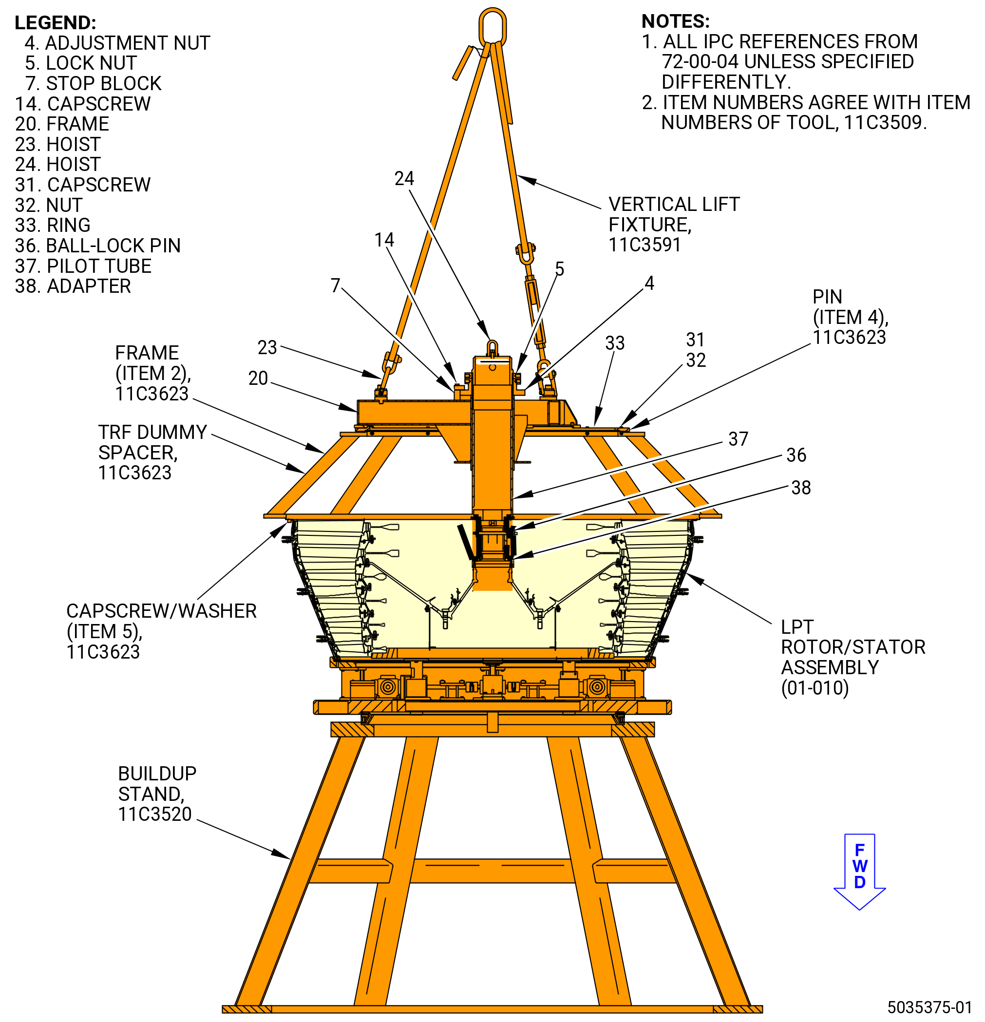
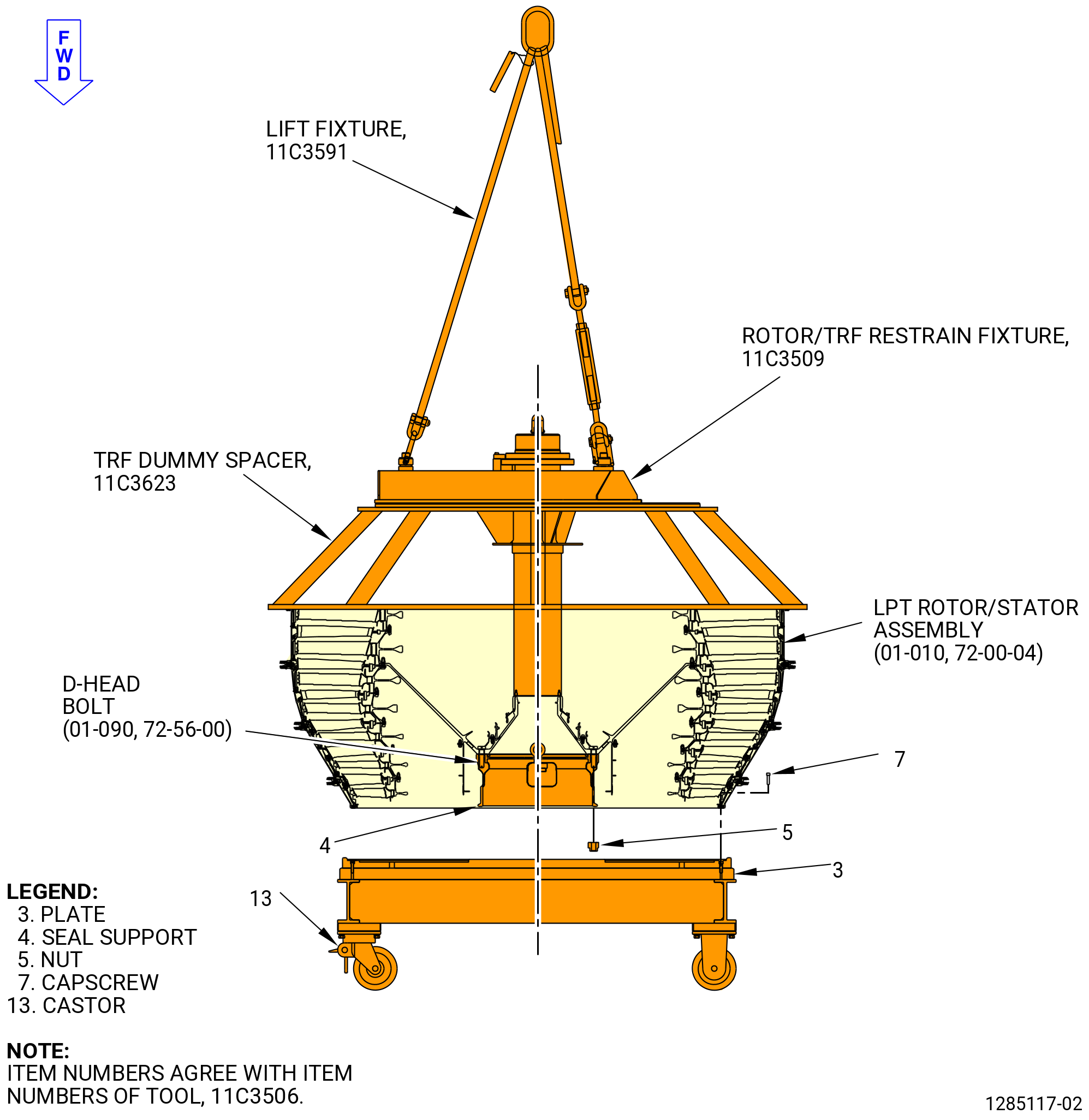
| A. | This procedure gives instructions to assemble the low pressure turbine (LPT) rotor/stator assembly (01-010 , 72-00-04) for PRE SB 72-0040 engines. Refer to Figure 1001. |
| NOTE: |
|
| B. | Protective covers are to be installed on spare assemblies. |
| C. | Install all the bolts with the heads up and/or forward unless specific instructions are given. |
| D. | Do not turn the LPT rotor in a clockwise (CW) direction, aft looking forward (ALF). |
| E. | Examine surfaces where parts engage for high metal and a clean surface. Refer to TASK 72-00-04-200-801 (72-00-04, Low Pressure Turbine Module Assembly - Inspection) for high metal limits. If necessary, clean the areas where the parts will engage as follows: |
| WARNING: |
|
| WARNING: |
|
| WARNING: |
|
| (1) | Clean the rabbet area, the flange area and the tooling surfaces where the parts engage. Use a lint-free C10-182 cloth and C04-002 stoddard solvent, C04-035 isopropyl alcohol, C04-003 acetone, or 50-50 blend of alcohol that contains C04-035 isopropyl alcohol and C04-228 denatured ethyl alcohol. |
| F. | Apply the lubricants to the threads and the friction surfaces only. |
| G. | The torque values given in this procedure are the actual torque to apply to the fastener. If a torque multiplier is used, do the necessary calculations to find the specified torque, the value that appears on the scale or dial of the torque wrench. Refer to TASK 70-51-00-400-004 (TIGHTENING PRACTICES AND TORQUE VALUES) . |
| 2 . | Tools, Equipment, and Materials. |
| NOTE: |
|
| A. | Tools and Equipment. |
| (1) | Special Tools. |
| (2) | Standard Tools and Equipment. |
|
| (3) | Locally Manufactured Tools. None. |
| B. | Consumable Materials. |
|
| C. | Referenced Procedures. |
|
| D. | Expendable Parts. |
|
| 3 . | Procedure. |
| Subtask 72-56-00-440-001 |
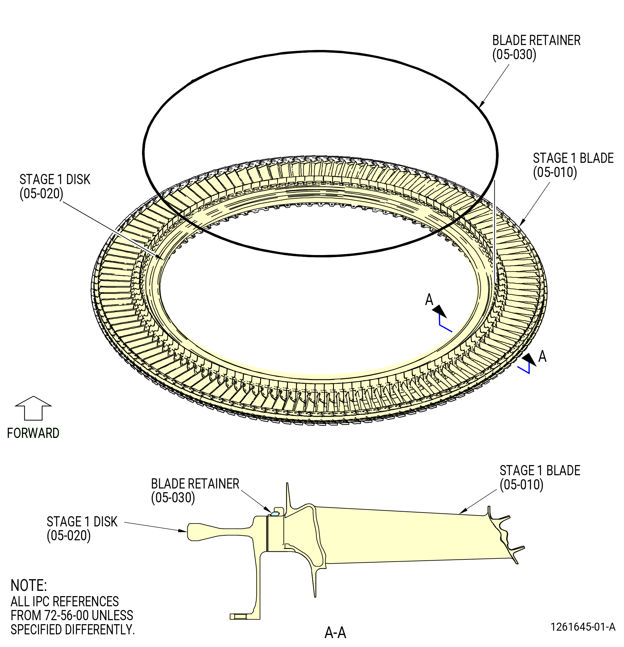
| A. | Assemble and balance the stage 1 LPTR disk (stage 1 disk) (05-020) (SIN 930B1), stage 1 LPT blades (stage 1 blades) (05-010) (SIN 930A1), and the blade retainers (05-030) (SIN 930W1) as follows. Refer to Figure 1002. |
| (1) | Install the balance adapter onto the balance machine. |
| Subtask 72-56-00-440-265 |
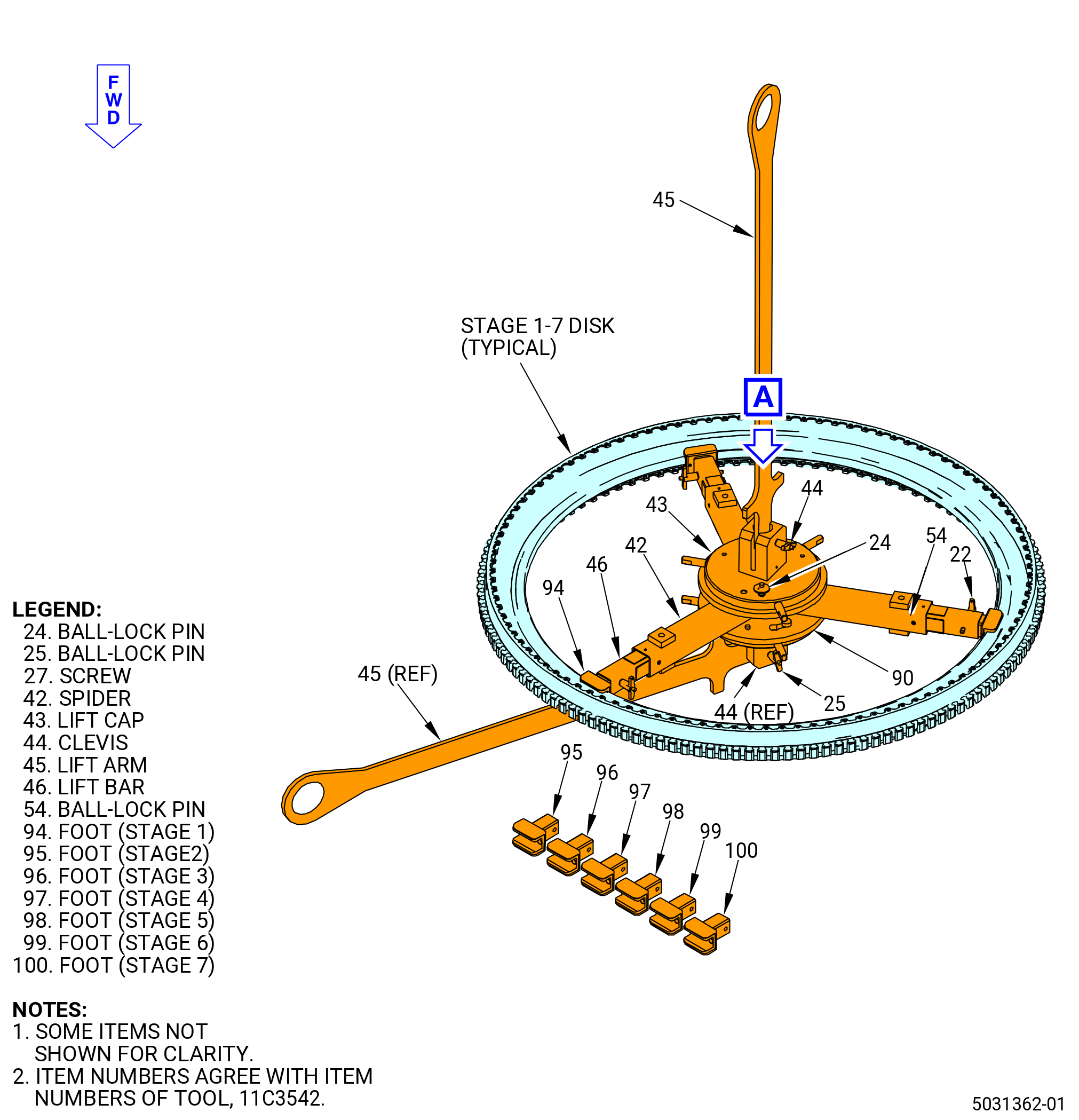
| (2) | Prepare the 11C3542 LPT disk lift/turn fixture to lift the stage 1 disk (05-020). Refer to Figure 1003 and do as follows: |
| (a) | Install the lift cap (item 43) onto the spider (42) at three locations and attach with the ball-lock pin (item 24). |
| (b) | Install the foot marked for stage 1 (item 94) at three locations into the lift bars (item 46) and attach with the ball-lock pins (item 54). |
| NOTE: |
|
| (c) | Install the lift bars (item 46) at three locations into the spider (item 42) and attach with the ball-lock pins (item 54). Keep one lift bar inward and not attached to the spider so the lift and turn fixture can be installed to the disk. |
| Subtask 72-56-00-440-189 |
| (3) | Attach the 11C3542 LPT disk lift/turn fixture to the stage 1 disk (05-020). Refer to Figure 1003 and do as follows: |
| (a) | Put the lift arm (item 45) in the lift cap (item 43) and attach with the ball-lock pin (item 25). |
| (b) | Attach a hoist to the lift arm (item 45). |
| WARNING: |
|
| CAUTION: |
|
| (c) | Carefully lift the 11C3542 LPT disk lift/turn fixture and lower it into the center of the disk. |
| (d) | While you lower the fixture, put the slot of the foot (item 94) into the stage 1 disk. |
| (e) | Extend the lift bar (item 46) that is not attached to the spider (item 42) and put the foot (item 94) into the inner diameter of the stage 1 disk. |
| (f) | Attach the lift bar (item 46) to the spider (item 42) with the ball-lock pin (item 54). |
| (g) | Make sure that the foot (item 94) at three locations engages the stage 1 disk. If not, make sure that you installed the correct foot (item 94) for the stage 1 disk. |
| Subtask 72-56-00-440-264 |
| (4) | Lift the stage 1 disk (05-020) and install, aft end down, on the balance machine. If the stage 1 disk is not in the correct position, turn the disk over as follows. Refer to Figure 1003. |
| (a) | Lift the 11C3542 LPT disk lift/turn fixture. |
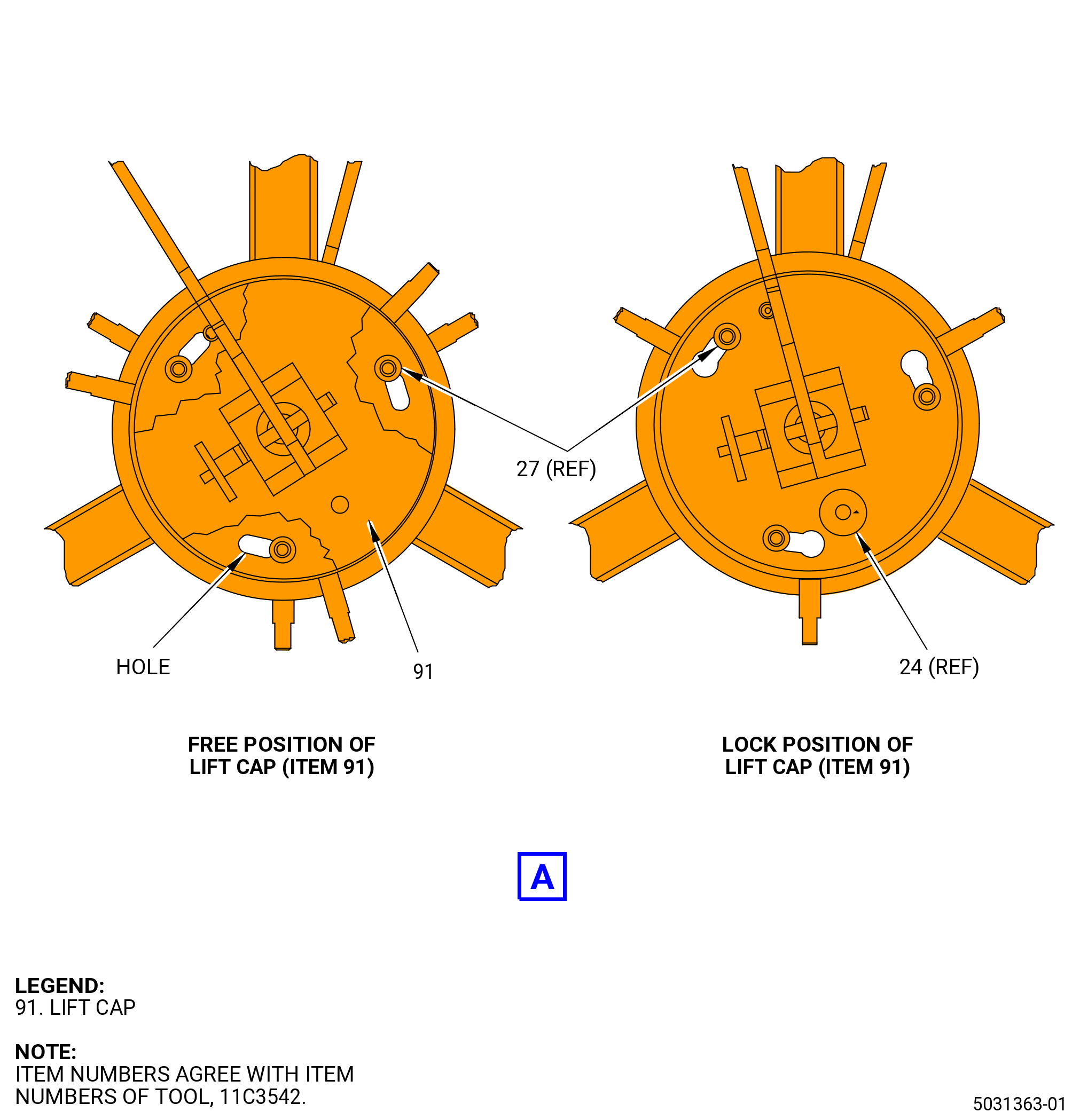
| (b) | Install the lift cap (item 91) onto the spider (item 42) and attach with the ball-lock pin (item 24). |
| (c) | Install the second lift arm (item 45) onto the lift cap (item 91) and attach with the ball-lock pin (item 25). |
| (d) | Attach a second hoist to the second lift arm (item 45). |
| (e) | Align the face of the lift arms (item 45) parallel to the plane of the hoists to make sure that there is a smooth rotation. |
| (f) | Lift the second lift arm (item 45) with the second hoist to turn the disk over. |
| (g) | Remove the first hoist from the first lift arm (item 45). |
| (h) | Remove the first ball-lock pin (item 25) and then the first lift arm (item 45). |
| (i) | Remove the ball-lock pin (item 24) and the lift cap (item 43). |
| (5) | Lower the stage 1 disk onto the balance machine with the aft end down. |
| Subtask 72-56-00-440-166 |
| (6) | Remove the 11C3542 LPT disk lift/turn fixture from the stage 1 disk (05-020). Refer to Figure 1003 and do as follows: |
| (a) | Remove the ball-lock pins (item 22) from the spider (item 2) at one location and retract the lift bar (item 46) to the inward position. |
| WARNING: |
|
| CAUTION: |
|
| (b) | While you lift the 11C3542 LPT disk lift/turn fixture from the stage 1 disk, carefully slide the foot (item 95) at two locations from the stage 1 disk. Put the hoist and the fixture in a safe location. |
| (7) | Set the balance machine to balance the stage 1 disk with the 9446M61 balance program. Record the stage 1 disk residual unbalance (FLA), weight (grams), and rpm. Refer to the balance machine manufacturer's instructions. |
| NOTE: |
|
| (a) | The correct R is 21.73 inches (552.0 mm). |
| (b) | The minimum speed is 600 rpm. |
| (8) | Attach the 11C3542 LPT disk lift/turn fixture to the stage 1 disk (05-020). |
| (9) | Remove the stage 1 disk from the balance machine. |
| (10) | Put a mark with a C05-003 pen at the top vertical centerline (TVCL) on the forward side of the stage 1 disk. |
| (11) | Moment weigh and plot blades with the 9446M61 balance program, or by blade mapping. Number all the blades stage 1 blades (05-010) (SIN 930A1) with a C05-003 pen on the inner dovetail of the blade. |
| (12) | Attach the 11C3542 LPT disk lift/turn fixture to the stage 1 disk. Refer to Subtask 72-56-00-440-189 (paragraph 3.A.(3)). |
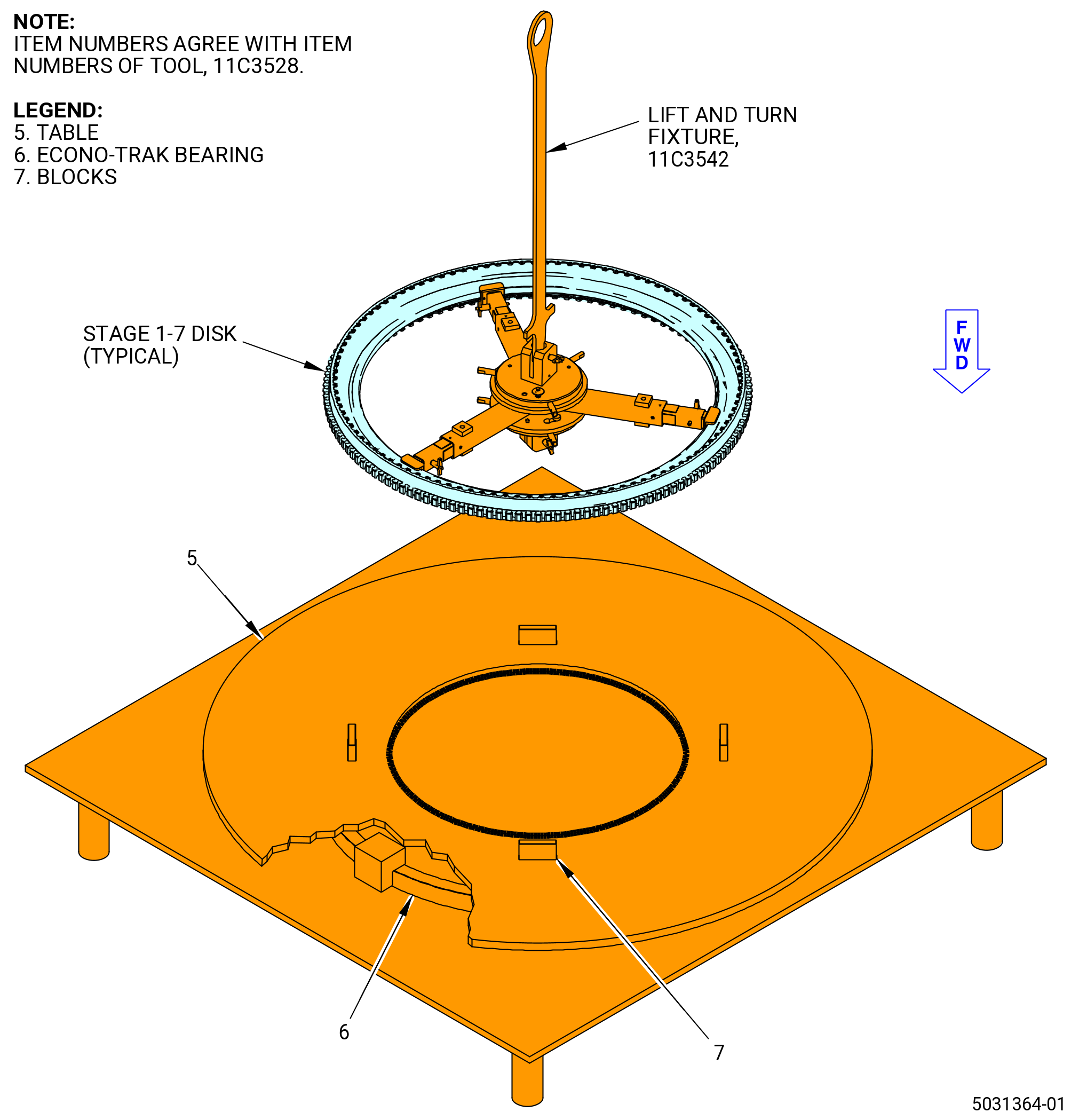
| (13) | Put the table (item 5) on the 11C3528 rotary table on the econo-trak bearing (item 6). Make sure that the 11C3528 rotary table is level. Refer to Figure 1004. |
| (14) | Put the blocks (item 7) on the table (item 5) to support the stage 1 disk (05-020) and stage 1 blades (05-010) at three locations. |
| (15) | Lift the stage 1 disk (05-020) and put it, aft end down, on the 11C3528 rotary table. |
| (16) | Apply C02-033 lubricant to the dovetails and the tip shroud interlock faces of the stage 1 blades. |
| (17) | Put the stage 1 blades, with the leading edge up, on the stage 1 disk, and align the blade dovetail with the disk dovetail slot. |
| (18) | Lower the stage 1 blades into the stage 1 disk until the dovetails of the stage 1 blades touch the stage 1 disk. Make sure that the blade dovetails are aligned with the disk dovetail slots. |
| CAUTION: |
|
| (19) | Tap the dovetails of the stage 1 blades with a non-metallic tool. Continue to tap the stage 1 blades until they are fully installed into the stage 1 disk (05-020). |
| (20) | Make sure that the blade tip shroud interlock surface has positive contact. |
| (21) | Install the blade retainers (05-030) at two locations on the stage 1 disk (05-020) as follows. Refer to Figure 1005. |
| Subtask 72-56-00-640-029 |
| (a) | Apply C02-033 lubricant to all the surfaces of the blade retainers (05-030). |
| Subtask 72-56-00-440-176 |
| (b) | Start the blade retainers at one of the free ends. |
| (c) | Twist the blade retainers 25-35 degrees and push them radially into the groove. |
| (d) | Use a non-metallic hammer and drift until the blade retainers are fully installed into the groove. |
| Subtask 72-56-00-440-042 |
| (22) | Attach the 11C3542 LPT disk lift/turn fixture to the stage 1 disk (05-020). Refer to Subtask 72-56-00-440-189 (paragraph 3.A.(3)). |
| WARNING: |
|
| (23) | Lift and install the stage 1 disk and stage 1 blades (05-010), aft side down, in the balance machine. Refer to the manufacturer's instructions for installation. |
| (24) | Remove the 11C3542 LPT disk lift/turn fixture from the stage 1 disk. Refer to Subtask 72-56-00-440-166 (paragraph 3.A.(6)). |
| (25) | Refer to the manufacturer's instructions and balance the LPT stage 1 disk and blade assembly as follows: |
| WARNING: |
|
| (a) | Turn the LPT stage 1 disk and blade assembly CCW, ALF, at no less than 600 rpm. |
| (b) | Do not add or remove any material to balance. |
| (c) | Make a mark with a C05-003 pen at the dovetail slot of the heavy-angle (area of unbalance) and the light-angle. |
| NOTE: |
|
| (d) | Disengage the LPT stage 1 disk from the balance machine. Refer to manufacturer's instructions for removal. |
| (e) | If the unbalance of the LPT stage 1 disk and blade assembly is more than 105 gram-inches (2667 grams-mm), move the LPT stage 1 disk and blade assembly to the 11C3528 rotary table and arrange the stage 1 blades to bring the unbalance within limits. Refer to the manufacturer's instructions to balance the LPT stage 1 disk and blade assembly until the unbalance of the stage 1 disk and blade assembly is less than 105 gram-inches (2667 grams-mm). |
| (26) | Attach the 11C3542 LPT disk lift/turn fixture to the balanced stage 1 disk and blade assembly as follows. Refer to Subtask 72-56-00-440-189 (paragraph 3.A.(3)). |
| (27) | Lift the stage 1 disk and blade assembly from the balance machine and put the assembly in a safe location. |
| (28) | Remove the 11C3542 LPT disk lift/turn fixture from the stage 1 disk and blade assembly as follows. Refer to Subtask 72-56-00-440-166 (paragraph 3.A.(6)). |
| Subtask 72-56-00-440-004 |
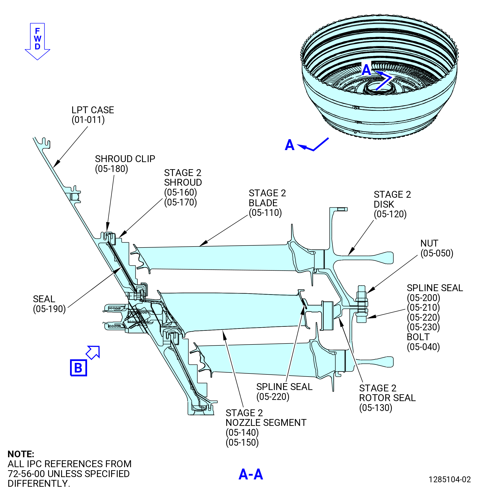
| B. | Assemble and balance the LPT rotor stage 2 disk (stage 2 disk) (05-120), the LPT rotor stage 2 blades (stage 2 blades) (05-110), and the LPT rotor stage 2 seal (stage 2 seal) (05-130) as follows. Refer to Figure 1006. |
| (1) | Put the stage 2 seal on the stage 2 disk and align the boltholes. |
| CAUTION: |
|
| (2) | Install the four bolts (item 2) of the 11C3576 dummy bolt/spacer and the 0.25-28UNJF-3B slave nuts at four locations in equal spaces on the stage 2 disk and the stage 2 seal. Tighten the slave nuts, but do not torque. Refer to Figure 1007. |
| (3) | If necessary, install the balance adapter onto the balance machine for the stage 2 disk and blade assembly. |
| Subtask 72-56-00-440-266 |
| (4) | Prepare the 11C3542 LPT disk lift/turn fixture to lift the stage 2 disk (05-120). Refer to Figure 1003 and do as follows: |
| (a) | Install the lift cap (item 43) onto the spider (item 42) and insert the ball-lock pin (item 24). |
| (b) | Install the stage 2 foot (item 95) at three locations into the lift bars (item 46) and attach with the ball-lock pins (item 54). |
| NOTE: |
|
| (c) | Install the lift bars (item 46) at three locations into the spider (item 42) and attach with the ball-lock pins (item 54) at two locations. Keep one lift bar inward, not attached to the spider, for the 11C3542 LPT disk lift/turn fixture can be attached to the disk. |
| Subtask 72-56-00-440-267 |
| (5) | Attach the 11C3542 LPT disk lift/turn fixture to the stage 2 disk (05-120). Refer to Figure 1003 and do as follows: |
| (a) | Attach the lift arm (item 45) to the lift cap (item 43) with the ball-lock pin (item 25). |
| (b) | Attach a hoist to the lift arm (item 45). |
| WARNING: |
|
| CAUTION: |
|
| (c) | Carefully lift the 11C3542 LPT disk lift/turn fixture and lower it into the center of the stage 2 disk. |
| (d) | While you lower the fixture, put the foot (item 95) at two locations into the stage 2 disk. |
| (e) | Extend the third lift bar (item 46) outward and put the foot (item 95) into the stage 2 disk. |
| (f) | Attach the third lift bar (item 46) to the spider (item 42) with the ball-lock pin (item 54). |
| (g) | Make sure the foot (item 95) at three locations engages the stage 1 disk. If not, make sure you installed the correct foot (item 95) for the stage 2 disk. |
| (6) | Lift the stage 2 disk (05-120) and install aft end down on the balance machine. |
| (a) | If the disk is not in the correct position, turn the disk over. Refer to Subtask 72-56-00-440-264 (paragraph 3.A.(4)). |
| Subtask 72-56-00-440-053 |
| (7) | Remove the 11C3542 LPT disk lift/turn fixture from the stage 2 disk. Refer to Figure 1003 and do as follows: |
| (a) | Remove the ball-lock pin (item 54) from the lift bar (item 46) at one location. |
| (b) | Retract the lift bar (item 46) at one location to the inward position. |
| WARNING: |
|
| CAUTION: |
|
| (c) | While you carefully lift the 11C3542 LPT disk lift/turn fixture, slide the foot (item 95) at two locations from the stage 2 disk (05-120). |
| (d) | Put the hoist and the lift arm in a safe location. |
| (8) | Set the balance machine to balance the stage 2 disk. Record the stage 2 disk and seal residual unbalance (FLA), weight (grams), and rpm. Refer to the manufacturer's instructions. |
| NOTE: |
|
| (a) | The correct R is 23.07 inches (586.0 mm). |
| (b) | The minimum speed is 600 rpm. |
| (9) | Put a mark with a C05-003 pen at the TVCL on the forward side of the stage 2 disk. |
| (10) | Weigh and plot the stage 2 blades (05-110) (SIN 930A2) with the 9446M61 balance program or by blade mapping. Number all the blades with a C05-003 pen on the inner dovetail of the blade. |
| (11) | Attach the 11C3542 LPT disk lift/turn fixture to the stage 2 disk. Refer to Subtask 72-56-00-440-267 (paragraph 3.B.(5)). |
| (12) | Lift the stage 2 disk and put it, aft end down, on the 11C3528 rotary table. Refer to Figure 1004. |
| (13) | Remove the 11C3542 LPT disk lift/turn fixture from the stage 2 disk. Refer to Subtask 72-56-00-440-053 (paragraph 3.B.(7)). |
| CAUTION: |
|
| (14) | Remove the slave nuts and the bolts (item 2) of the 11C3576 dummy bolt/spacer from the stage 2 seal (05-130) and from the stage 2 disk (05-120). Refer to Figure 1007. |
| (15) | Remove the stage 2 seal from the stage 2 disk. |
| Subtask 72-56-00-640-003 |
| (16) | Apply C02-033 lubricant to the dovetails and the tip shroud interlock faces of the stage 2 blades (05-110). |
| Subtask 72-56-00-440-111 |
| (17) | Put the stage 2 blades (05-110), with the leading edge up, on the stage 2 disk (05-120). Align the blade dovetail with the disk dovetail slot. |
| (18) | Lower the stage 2 blades until the dovetails touch the stage 2 disk. Make sure that the blade dovetails are aligned with the disk dovetail slots. |
| CAUTION: |
|
| (19) | Tap the dovetails of the stage 2 blades with a non-metallic tool. Continue to tap the stage 2 blades until they are fully installed into the stage 2 disk. |
| Subtask 72-56-00-640-004 |
| (20) | Apply C02-058 graphite to the threads and washer faces of the bolts (item 2) of the 11C3576 dummy bolt/spacer and the 0.250-28UNJF-3B slave nuts at four locations. Use the 11C3576 dummy bolt/spacer and slave nuts for the static balance and not the assembly bolts (05-040) and nuts (05-050). Refer to Figure 1007. |
| Subtask 72-56-00-440-049 |
| (21) | Put the stage 2 seal (05-130) on the stage 2 disk (05-120) and align with the holes in the stage 2 disk. Refer to Figure 1006. |
| (22) | Install the bolts (item 2) of the 11C3576 dummy bolt/spacer and the 0.25-28UNJF-3B slave nuts at four locations in equal spaces on the stage 2 disk and the stage 2 seal. Refer to Figure 1007. |
| CAUTION: |
|
| (23) | Torque the slave nuts to 78-91 lb in. (8.8-10.3 N.m). Use the wrench (item 2) of the 11C3560 nut wrench to turn and tighten the nut. |
| NOTE: |
|
| (24) | Remove any lubricant that remains with a clean C10-182 cloth. |
| (25) | Put a mark with a C05-003 pen at the location of the bolts (item 2) of the 11C3576 dummy bolt/spacer on the stage 2 seal and the stage 2 disk. Refer to Figure 1007 |
| (26) | Attach the 11C3542 LPT disk lift/turn fixture to the stage 2 disk (05-120). Refer to Subtask 72-56-00-440-267 (paragraph 3.B.(5)). |
| WARNING: |
|
| (27) | Lift and install the stage 2 disk and stage 2 blades (05-110), aft side down, on the balance machine. Refer to the manufacturer's instructions for installation. |
| (28) | Remove the 11C3542 LPT disk lift/turn fixture from the stage 2 disk. Refer to Subtask 72-56-00-440-053 (paragraph 3.B.(7)). |
| (29) | Refer to the manufacturer's instructions to balance the stage 2 disk and blade assembly. |
| WARNING: |
|
| (a) | Turn the stage 2 disk and blade assembly CCW, ALF, at no less than 600 rpm. |
| (b) | Do not add or remove any material to balance. |
| (c) | Put a mark with a C05-003 pen at the dovetail slot of the heavy-angle (area of unbalance) and the light-angle. |
| NOTE: |
|
| (d) | Disengage the stage 2 disk from the balance machine. Refer to the manufacturer's instructions for removal. |
| (e) | If the unbalance of the stage 2 disk and blade assembly is more than 105 gram-inches (2667 grams-mm), move the stage 2 disk and blade assembly to the 11C3528 rotary table and arrange the stage 2 blades to bring the unbalance within limits. Refer to the manufacturer's instructions to balance the stage 2 disk and blade assembly until the unbalance of the stage 2 disk and blade assembly is less than 105 gram-inches (2667 grams-mm). |
| (30) | Attach the 11C3542 LPT disk lift/turn fixture to the balanced stage 2 disk. Refer to Subtask 72-56-00-440-267 (paragraph 3.B.(5)). |
| WARNING: |
|
| (31) | Lift the stage 2 disk and blade assembly from the balance machine and put the assembly in a safe location. |
| (32) | Remove the 11C3542 LPT disk lift/turn fixture from the stage 2 disk and blade assembly. Refer to Subtask 72-56-00-440-053 (paragraph 3.B.(7)). |
| Subtask 72-56-00-440-005 |
| C. | Assemble and balance the LPT rotor stage 3 disk (stage 3 disk) (05-290), stage 3 blades (05-280), and the LPT rotor stage 3 seal (stage 3 rotor seal) (05-300) as follows. Refer to Figure 1008. |
| (1) | Put the stage 3 seal on the stage 3 disk and align the boltholes. |
| CAUTION: |
|
| (2) | Install the four bolts (item 2) of the 11C3576 dummy bolt/spacer and the 0.25-28UNJF-3B slave nuts at four locations in equal spaces on the stage 3 disk and the stage 3 seal. Tighten the slave nuts, do not torque the slave nuts. Refer to Figure 1007. |
| (3) | If necessary, install the balance adapter on the balance machine. |
| Subtask 72-56-00-440-268 |
| (4) | Prepare the 11C3542 LPT disk lift/turn fixture to lift the stage 3 disk (05-290). Refer to Figure 1003 and do as follows: |
| (a) | Install the lift cap (item 43) onto the spider (item 42) and attach with the ball-lock pin (item 24). |
| (b) | Install the stage 3 foot (item 96) at three locations into the lift bars (item 46) and attach with the ball-lock pins (item 54). |
| NOTE: |
|
| (c) | Install the lift bars (item 46) at three locations into the spider (item 42) and attach with the ball-lock pins (item 22) at two locations. Keep one lift bar inward, not attached to the spider, for the lift and turn fixture can be attached to the disk. |
| Subtask 72-56-00-440-269 |
| (5) | Attach the 11C3542 LPT disk lift/turn fixture to the stage 3 disk (05-290) as follows: |
| (a) | Attach the lift arm (item 45) to the lift cap (item 43) with the ball-lock pin (item 25). |
| (b) | Attach a hoist to the lift arm (item 45). |
| WARNING: |
|
| CAUTION: |
|
| (c) | Carefully lift the 11C3542 LPT disk lift/turn fixture and lower it into the center of the stage 3 disk. |
| (d) | While you lower the fixture, put the foot (item 96) at two locations into the stage 3 disk. |
| (e) | Extend the third lift bar (item 46) outward and put the foot (item 96) into the stage 3 disk. |
| (f) | Attach the third lift bar (item 46) to the spider (item 42) with the ball-lock pin (item 54). |
| (g) | Make sure that the foot (item 96) at three locations engages the stage 3 disk. If not, make sure you installed the correct foot (item 96) for the stage 3 disk. |
| Subtask 72-56-00-440-056 |
| WARNING: |
|
| (6) | Lift the stage 3 disk (05-290) and put it, aft end down, on the balance machine. |
| (a) | If the disk is not in the correct position, turn the disk over. Refer to Subtask 72-56-00-440-264 (paragraph 3.A.(4)). |
| Subtask 72-56-00-440-270 |
| (7) | Remove the 11C3542 LPT disk lift/turn fixture from the stage 3 disk and blade assembly. Refer to Figure 1003 and do as follows: |
| (a) | Remove the ball-lock pin (item 22) from the spider (item 42) at one location. |
| (b) | Retract the lift bar (item 46) at one location to the inward position. |
| CAUTION: |
|
| (c) | While you lift the 11C3542 LPT disk lift/turn fixture from the stage 3 disk, carefully slide the foot (item 96) from the stage 3 disk at two locations. |
| (d) | Put the 11C3542 LPT disk lift/turn fixture in a safe location. |
| (8) | Set the balance machine to balance the stage 3 disk (05-290). Record the stage 3 disk and (FLA), weight (grams), and rpm. Refer to the balance machine manufacturer's instructions. |
| NOTE: |
|
| (a) | The correct R is 24.72 inches (628.0 mm). |
| (b) | The minimum speed is 600 rpm. |
| (9) | Put a mark with a C05-003 pen at the TVCL on the forward side of the stage 3 disk. |
| (10) | Moment weigh and plot the stage 3 blades (05-280) (SIN 930A3) with the 9446M61 balance program or by blade mapping. Number all the blades with a C05-003 pen on the inner dovetail of the blade. |
| (11) | Attach the 11C3542 LPT disk lift/turn fixture to the stage 3 disk. Refer to Subtask 72-56-00-440-269 (paragraph 3.C.(5)). |
| (12) | Lift the stage 3 disk and put it, aft end down, on the 11C3528 rotary table. Refer to Figure 1004. |
| (13) | Remove the 11C3542 LPT disk lift/turn fixture from the stage 3 disk (05-290). Refer to Subtask 72-56-00-440-270 (paragraph 3.C.(7)). |
| (14) | Remove the slave nuts and the bolts (item 2) of the 11C3576 dummy bolt/spacer from the stage 3 seal (05-300) and stage 3 disk (05-290). Refer to Figure 1007. |
| (15) | Remove the stage 3 seal from the stage 3 disk. |
| Subtask 72-56-00-640-005 |
| (16) | Apply C02-033 lubricant to the dovetails and the tip shroud interlock faces of the stage 3 blades (05-280). |
| Subtask 72-56-00-440-112 |
| (17) | Put the stage 3 blades (05-280), with the leading edge up, on the stage 3 disk (05-290). Align the blade dovetail with the disk dovetail slot. |
| (18) | Lower the stage 3 blades until the dovetails touch the stage 3 disk. Make sure that the blade dovetails are aligned with the disk dovetail slots. |
| CAUTION: |
|
| (19) | Tap the dovetails of the stage 3 blades with a non-metallic tool. Continue to lower and tap the stage 3 blades until they are fully installed into the stage 3 disk. |
| (20) | Make sure that the blade tip shroud interlock surface has positive contact. |
| Subtask 72-56-00-640-006 |
| (21) | Apply C02-058 graphite to the threads and washer faces of four bolts (item 2) of the 11C3576 dummy bolt/spacer and 0.250-28UNJF-3B slave nuts. Use the bolts of the 11C3576 dummy bolt/spacer and slave nuts for the static balance. Do not use the assembly bolts (05-310) and nuts (05-320). Refer to Figure 1006. |
| Subtask 72-56-00-440-059 |
| (22) | Put the stage 3 rotor seal (05-300) on the stage 3 disk (05-290) and align with the holes in the stage 3 disk. Refer to Figure 1008. |
| (23) | Install the four bolts (item 2) of the 11C3576 dummy bolt/spacer and the slave nuts at equal spaces to the stage 3 disk and the stage 3 rotor seal. Refer to Figure 1007. |
| CAUTION: |
|
| (24) | Torque the slave nuts to 78-91 lb in. (8.8-10.3 N.m). Use the wrench (item 2) of the 11C3560 nut wrench to turn and tighten the nut. |
| NOTE: |
|
| (25) | Remove any lubricant that remains with a clean C10-182 cloth. |
| (26) | Put a mark with a C05-003 pen at the bolt locations on the stage 3 rotor seal and the stage 3 disk. |
| (27) | Install the 11C3542 LPT disk lift/turn fixture on the stage 3 disk and blade assembly. Refer to Subtask 72-56-00-440-269 (paragraph 3.C.(5)). |
| (28) | Lift and install the stage 3 disk and blade assembly, aft side down, on the balance machine. Refer to the manufacturer's instructions for installation. |
| (29) | Remove the 11C3542 LPT disk lift/turn fixture from the stage 3 disk and blade assembly. Refer to Subtask 72-56-00-440-270 (paragraph 3.C.(7)). |
| (30) | Refer to the manufacturer's instructions to balance the stage 3 disk (05-290) and stage 3 blade (05-280). |
| WARNING: |
|
| (a) | Turn the stage 3 disk and blade assembly CCW, ALF, at no less than 600 rpm. |
| (b) | Do not add or remove any material to balance. |
| (c) | Put a mark with a C05-003 pen at the dovetail slot of the heavy-angle (area of unbalance) and the light-angle. |
| NOTE: |
|
| (d) | Disengage the stage 3 disk from the balance machine. Refer to the manufacturer's instructions for removal. |
| (e) | If the unbalance of the stage 3 disk and blade assembly is more than 105 gram-inches (2667 grams-mm), move the stage 3 disk and blade assembly to the 11C3528 rotary table and arrange the stage 3 blades to bring the unbalance within limits. Refer to the manufacturer's instructions to balance the stage 3 disk and blade assembly until the unbalance of the stage 3 disk and blade assembly is less than 105 gram-inches (2667 grams-mm). |
| Subtask 72-56-00-440-062 |
| (31) | Attach the 11C3542 LPT disk lift/turn fixture to the balanced stage 3 disk and stage 3 blade. Refer to Subtask 72-56-00-440-269 (paragraph 3.C.(5)). |
| WARNING: |
|
| (32) | Lift the stage 3 disk and blade assembly from the balance machine and put the assembly in a safe location. |
| (33) | Remove the 11C3542 LPT disk lift/turn fixture from the stage 3 disk and blade assembly. Refer to Subtask 72-56-00-440-270 (paragraph 3.C.(7)). |
| Subtask 72-56-00-440-006 |
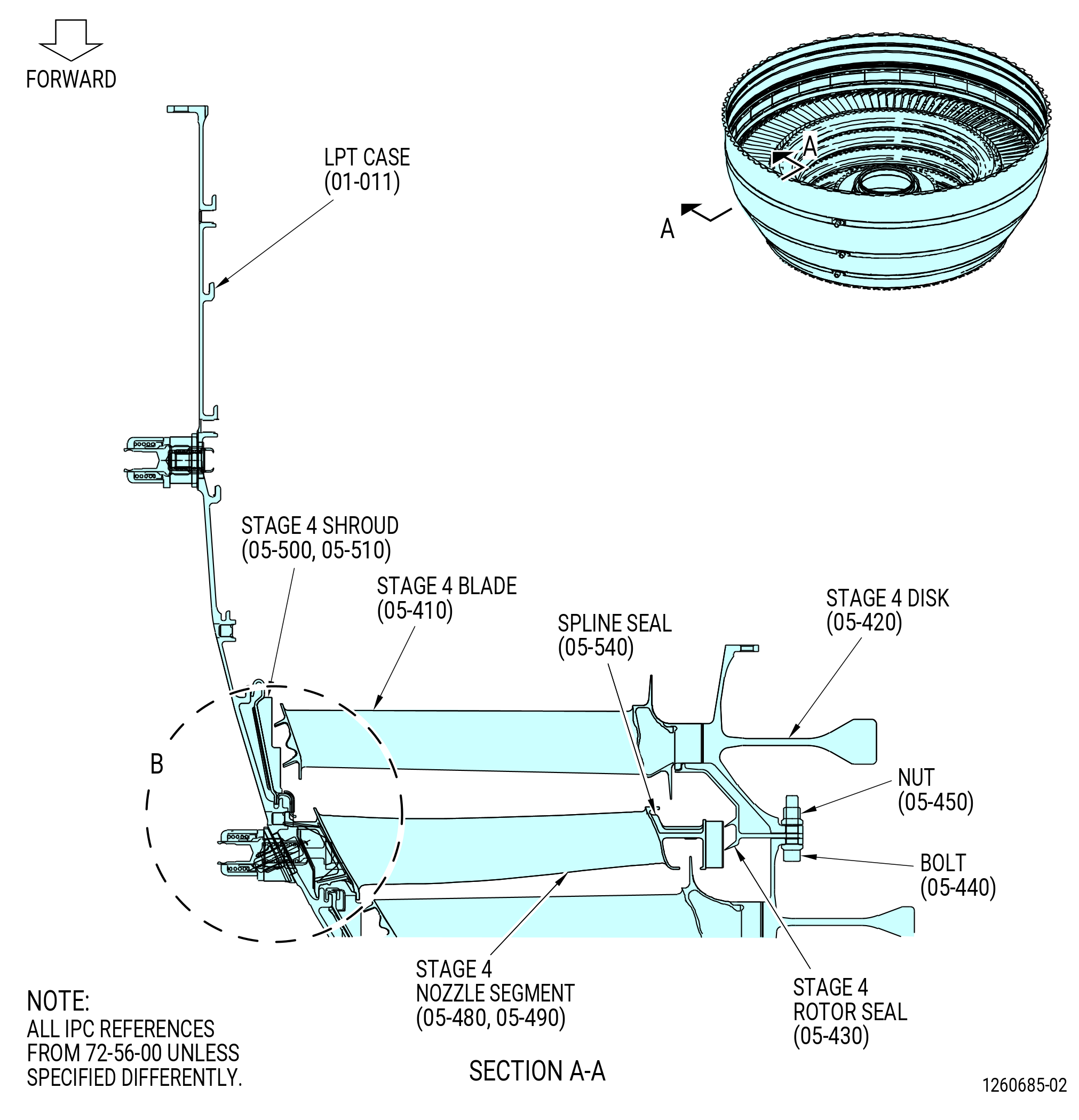
| D. | Assemble and balance the stage 4 disk (05-420), the stage 4 blades (05-410), and the LPT rotor stage 4 seal (stage 4 rotor seal) (05-430) as follows. Refer to Figure 1009. |
| (1) | Put the stage 4 seal on the stage 4 disk. |
| CAUTION: |
|
| (2) | Install the four bolts (item 2) of the 11C3576 dummy bolt/spacer and the 0.25-28UNJF-3B slave nuts at four locations in equal spaces on the stage 4 disk and the stage 4 seal. Tighten the slave nuts, but do not torque the slave nuts. Refer to Figure 1007. |
| (3) | If necessary, install the balance adapter onto the balance machine. |
| Subtask 72-56-00-440-280 |
| (4) | Prepare the 11C3542 LPT disk lift/turn fixture to lift the stage 4 disk (05-420). Refer to Figure 1003 and do as follows: |
| (a) | Install the lift cap (item 43) onto the spider (item 42) and attach with the ball-lock pin (item 24). |
| (b) | Install the stage 4 foot (item 97) at three locations into the lift bars (item 46) and attach with the ball-lock pins (item 54). |
| NOTE: |
|
| (c) | Install the lift bars (item 46) at three locations into the spider (item 42) and attach ball-lock pins (item 22). Keep one lift bar inward, not attached to the spider, for the lift and turn fixture can be attached to the disk. |
| Subtask 72-56-00-440-271 |
| (5) | Attach the 11C3542 LPT disk lift/turn fixture to the stage 4 disk (05-420). Refer to Figure 1003 and do as follows: |
| (a) | Install the lift arm (item 45) into the lift cap (item 43) and attach with the ball-lock pin (item 25). |
| (b) | Attach a hoist to the lift arm (item 45). |
| WARNING: |
|
| CAUTION: |
|
| (c) | Carefully lift the 11C3542 LPT disk lift/turn fixture and lower it into the center of the stage 4 disk. |
| (d) | While you lower the fixture, put the foot (item 97) at two locations into the stage 4 disk. |
| (e) | Extend the third lift bar (item 46) outward and put the foot (item 97) into the stage 4 disk. |
| (f) | Attach the third lift bar (item 46) to the spider (item 42) with the ball-lock pin (item 54). Make sure the foot (item 97) is in the disk at three locations. If not, make sure you have installed the correct foot (item 97) for the stage 4 disk. |
| Subtask 72-56-00-440-066 |
| WARNING: |
|
| (6) | Lift the stage 4 disk (05-420) and put it, aft end down, on the balance machine. |
| (a) | If the disk is not in the correct position, turn the disk over. Refer to Subatsk 72-56-00-440-264 (paragraph 3.A.(4)). |
| Subtask 72-56-00-440-272 |
| (7) | Remove the 11C3542 LPT disk lift/turn fixture from the stage 4 disk (05-420). Refer to Figure 1003 and do as follows: |
| (a) | Remove the ball-lock pins (item 54) from the lift bar (item 46) at one location and retract the lift bar (item 46) to the inward position. |
| WARNING: |
|
| CAUTION: |
|
| (b) | While you carefully lift the 11C3542 LPT disk lift/turn fixture, slide the foot (item 97) from the stage 4 disk (05-420) at two locations. |
| (c) | Put the hoist and the lift arm in a safe location. |
| (8) | Set the balance machine to balance the stage 4 disk (05-420). Record the stage 4 disk and (FLA), weight (grams), and rpm. Refer to the balance machine manufacturer's instructions. |
| NOTE: |
|
| (a) | The correct R is 26.42 inches (671.0 mm). |
| (b) | The minimum speed is 600 rpm. |
| (9) | Put a mark with a C05-003 pen at the TVCL on the forward side of the stage 4 disk. |
| (10) | Weigh and plot the stage 4 blades (05-410) (SIN 930A4) with the 9446M61 balance program or by blade mapping. Number all the blades with a C05-003 pen on the inner dovetail of the blade. |
| (11) | Attach the 11C3542 LPT disk lift/turn fixture to the stage 4 disk. Refer to Subtask 72-56-00-440-271 (paragraph 3.D.(5)). |
| WARNING: |
|
| (12) | Lift the stage 4 disk and put it, aft end down, on the 11C3528 rotary table. Refer to Figure 1004. |
| (13) | Remove the 11C3542 LPT disk lift/turn fixture from the stage 4 disk. Refer to Subtask 72-56-00-440-272 (paragraph (3.D.(7)). |
| (14) | Remove the slave nuts and the bolts (item 2) of the 1C3576 dummy bolt/spacer from the stage 4 seal (05-430) and from the stage 4 disk. Remove the stage 4 seal from the stage 4 disk. Refer to Figure 1007. |
| Subtask 72-56-00-640-007 |
| (15) | Apply C02-033 lubricant to the dovetails and the tip shroud interlock faces of the stage 4 blades (05-410). |
| Subtask 72-56-00-440-113 |
| (16) | Put the stage 4 blades (05-410), with the leading edge up, on the stage 4 disk (05-420). Align the blade dovetail with the disk dovetail slot. |
| (17) | Lower the stage 4 blades until the dovetails touch the stage 4 disk. Make sure that the blade dovetails are aligned with the disk dovetail slots. |
| CAUTION: |
|
| (18) | Tap the dovetails of the stage 4 blades with a non-metallic tool. Continue to lower and tap the stage 4 blades until they are fully installed into the stage 4 disk. |
| (19) | Apply C02-058 graphite to the threads and washer faces of the four bolts (item 2) of the 11C3576 dummy bolt/spacer and the 0.250-28UNJF slave nuts. Use the bolts (item 2) of the 11C3576 dummy bolt/spacer and slave nuts for the static balance and not the assembly D-head bolts (05-460) and nuts (05-470). Refer to Figure 1007. |
| (20) | Put the stage 4 seal (05-430) on the stage 4 disk (05-420) and align with the holes in the stage 4 disk. Refer to Figure 1009. |
| (21) | Install the bolts (item 2) of the 11C3576 dummy bolt/spacer and the 0.25-28UNJF-3B slave nuts at four locations in equal spaces on the stage 4 disk and the stage 4 seal. Refer to Figure 1007. |
| (22) | Torque the slave nuts to 78-91 lb in. (8.8-10.3 N.m). Use the wrench (item 2) of the 11C3560 nut wrench to turn and tighten the nuts. |
| NOTE: |
|
| (23) | Remove any lubricant that remains with a clean C10-182 cloth. |
| (24) | Put a mark with a C05-003 pen at the location of the four bolts (item 2) of the 11C3560 nut wrench on the stage 4 rotor seal (05-430) and the stage 4 disk (05-420). |
| (25) | Attach the 11C3542 LPT disk lift/turn fixture to the stage 4 disk (05-420). Refer to Subtask 72-56-00-440-271 (paragraph 3.D.(5)). |
| WARNING: |
|
| (26) | Lift and install the stage 4 disk and blade assembly, aft side down, into the balance machine. Refer to the manufacturer's instructions for installation. |
| (27) | Remove the 11C3542 lift and turn fixture from the stage 4 disk. Refer to Subtask 72-56-00-440-272 (paragraph 3.D.(7)). |
| (28) | Refer to the manufacturer's instructions to balance the stage 4 disk (05-420) (SIN 930B4) and stage 4 blades (05-410) (SIN 930A4) as follows: |
| WARNING: |
|
| (a) | Turn the stage 4 disk and blade assembly CCW, ALF, at no less than 600 rpm. |
| (b) | Do not add or remove any material to balance. |
| (c) | Put a mark with a C05-003 pen at the dovetail slot of the heavy-angle (area of unbalance) and the light-angle. |
| NOTE: |
|
| (d) | Disengage the stage 4 disk from the balance machine. Refer to the manufacturer's instructions for removal. |
| (e) | If the unbalance of the stage 4 disk and blade assembly is more than 105 gram-inches (2667 grams-mm), move the stage 4 disk and blade assembly to the 11C3528 rotary table and arrange the stage 4 blades to bring the unbalance within limits. Refer to the manufacturer's instructions to balance the stage 4 disk and blade assembly until the unbalance of the stage 4 disk and blade assembly is less than 105 gram-inches (2667 grams-mm). |
| Subtask 72-56-00-440-071 |
| (29) | Attach the 11C3542 LPT disk lift/turn fixture to the balanced stage 4 disk and blade assembly. Refer to Subtask 72-56-00-440-271 (paragraph 3.D.(5)). |
| WARNING: |
|
| (30) | Lift the stage 4 disk and blade assembly from the balance machine and put the assembly in a safe location. |
| (31) | Remove the 11C3542 LPT disk lift/turn fixture from the stage 4 disk. Refer to Subtask 72-56-00-440-272 (paragraph 3.D.(7)). |
| (32) | Deleted. |
| (33) | Deleted. |
| Subtask 72-56-00-440-007 |
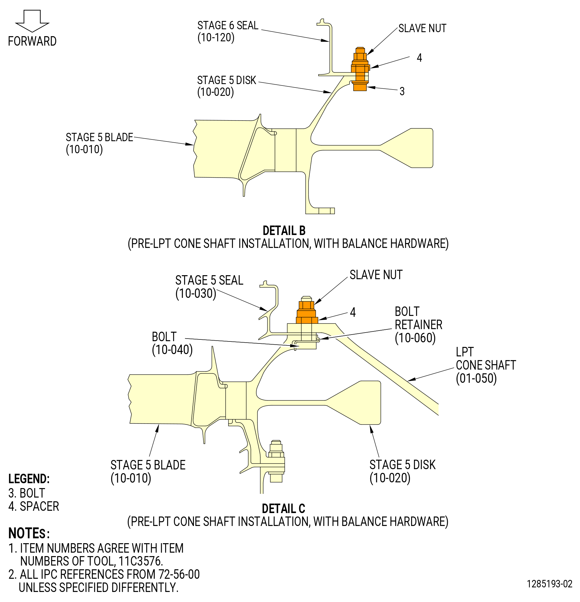
| E. | Assemble and balance the LPT rotor stage 5 disk (stage 5 disk) (10-020), the LPT rotor stage 5 blades (stage 5 blades) (10-010), and the LPT rotor stage 5 seal (stage 5 rotor seal) (10-030) as follows. Refer to Figure 1010. |
| (1) | Put the stage 5 rotor seal on the stage 5 disk (10-020). |
| CAUTION: |
|
| (2) | Install the four bolts (item 2) of the 11C3576 dummy bolt/spacer and the 0.25-28UNJF-3B slave nuts at four locations in equal spaces on the stage 5 disk and the stage 5 rotor seal. Tighten the slave nuts loosely. Refer to Figure 1007. |
| (3) | If necessary, install the balance adapter onto the balance machine. |
| Subtask 72-56-00-440-273 |
| (4) | Prepare the 11C3542 LPT disk lift/turn fixture to lift the stage 5 disk. Refer to Figure 1003 and do as follows: |
| (a) | Install the lift cap (item 43) onto the spider (item 42) and attach with the ball-lock pin (item 24). |
| (b) | Install the stage 5 foot (item 98) at three locations into the lift bars (item 46) and attach the ball-lock pins (item 54). |
| NOTE: |
|
| (c) | Install the lift bars (item 46) at three locations into the spider (item 42) and attach with the ball-lock pins (item 54) at two locations. Keep one lift bar inward, not attached to the spider, for the 11C3542 LPT disk lift/turn fixture can be attached to the disk. |
| Subtask 72-56-00-440-274 |
| (5) | Attach the 11C3542 LPT disk lift/turn fixture to the stage 5 disk (10-020). Refer to Figure 1003 and do as follows: |
| (a) | Install the lift arm (item 45) into the lift cap (item 43) and attach with the ball-lock pin (item 25). |
| (b) | Attach a hoist to the lift arm (item 45). |
| WARNING: |
|
| CAUTION: |
|
| (c) | Carefully lift the 11C3542 LPT disk lift/turn fixture and lower it into the center of the stage 5 disk. |
| (d) | While you lower the fixture, put the foot (item 98) at two locations into the stage 5 disk. |
| (e) | Extend the third lift bar outward and put the foot (item 98) into the stage 5 disk. |
| (f) | Attach the third lift arm (item 46) to the spider (item 42) with a ball-lock pin (item 54). |
| (g) | Make sure that the foot (item 98) at three locations engages the stage 5 disk. If not, make sure you installed the correct foot (item 98) for the stage 5 disk. |
| Subtask 72-56-00-440-073 |
| WARNING: |
|
| (6) | Lift the stage 5 disk (10-020) and install it, aft end down, on the balance machine. |
| (a) | If the disk is not in the correct position, turn the disk over. Refer to Subtask 72-56-00-440-264 (paragraph 3.A.(4)). |
| Subtask 72-56-00-440-275 |
| (7) | Remove the 11C3542 LPT disk lift/turn fixture from the stage 5 disk. Refer to Figure 1003 and do as follows: |
| (a) | Remove the ball-lock pin (item 54) from the spider (item 42) at one location. |
| (b) | Retract the lift arms (item 46) at one location to the inward position. |
| CAUTION: |
|
| (c) | While you carefully lift the 11C3542 LPT disk lift/turn fixture, slide the foot (item 98) at two locations from the stage 5 disk. |
| (d) | Put the 11C3542 LPT disk lift/turn fixture in a safe location. |
| (8) | Set the balance machine to balance the stage 5 disk. Record the stage 5 disk and (FLA), weight (grams), and rpm. Refer to the balance machine manufacturer's instructions. |
| NOTE: |
|
| (a) | The correct R is 26.54 inches (674.0 mm). |
| (b) | The minimum speed is 600 rpm. |
| (9) | Put a mark with a C05-003 pen at the TVCL on the forward side of the stage 5 disk (10-020). |
| (10) | Weigh and plot the stage 5 blades (10-010) (SIN 930A5) with the 9446M61 balance program or by blade mapping. Number all the blades with a C05-003 pen on the inner dovetail of the blade. |
| (11) | Attach the 11C3542 LPT disk lift/turn fixture to the stage 5 disk. Refer to Subtask 72-56-00-440-274 (paragraph 3.E.(5)). |
| WARNING: |
|
| (12) | Lift the stage 5 disk and put it, aft end down, on the 11C3528 rotary table. Refer to Figure 1004. |
| (13) | Remove the 11C3542 LPT disk lift/turn fixture from the stage 5 disk and blade assembly. Refer to Subtask 72-56-00-440-275 (paragraph 3.E.(7)). |
| CAUTION: |
|
| (14) | Remove the slave nuts, bolts (item 2) and spacers (item 4) of the 11C3576 dummy bolt/spacer. Refer to Figure 1007. |
| (15) | Remove the stage 5 rotor seal (10-030) from the stage 5 disk. |
| Subtask 72-56-00-640-009 |
| CAUTION: |
|
| (16) | Apply C02-033 lubricant to the dovetails and the tip shroud interlock faces of the stage 5 blades (10-010). |
| Subtask 72-56-00-440-114 |
| (17) | Put the stage 5 blades (10-010), with the leading edge up, on the stage 5 disk (10-020). Align the blade dovetail with the disk dovetail slot. |
| (18) | Lower the stage 5 blades until the dovetails touch the stage 5 disk. Make sure that the blade dovetails are aligned with the disk dovetail slots. |
| CAUTION: |
|
| (19) | Tap the dovetails of the stage 5 blades (10-010) with a non-metallic tool. Continue to lower and tap the stage 5 blades until they are fully installed into the stage 5 disk. |
| Subtask 72-56-00-640-010 |
| (20) | Apply C02-058 graphite to the threads and washer faces of the four bolts (item 2) of the 11C3576 dummy bolt/spacer and the 0.250-28UNJF-3B slave nuts. |
| NOTE: |
|
| Subtask 72-56-00-440-076 |
| (21) | Put the stage 5 rotor seal (10-030) on the stage 5 disk (10-020) and align the holes in the stage 5 disk. |
| (22) | Install the four bolts (item 2) of the 11C3576 dummy bolt/spacer and the 0.25-28UNJF-3B slave nuts equally spaced to the stage 5 disk and the stage 5 rotor seal. Refer to Figure 1007. |
| CAUTION: |
|
| (23) | Torque the slave nuts to 78-91 lb in. (8.8-10.3 N.m). Use the wrench (item 2) of the 11C3576 dummy bolt/spacer to turn and tighten the nut. |
| NOTE: |
|
| (24) | Remove any lubricant that remains with a clean C10-182 cloth. |
| (25) | Put a mark with a C05-003 pen at the location of the four bolt (item 2) of the 11C3576 dummy bolt/spacer on the stage 5 rotor seal and the stage 5 disk. Refer to Figure 1007. |
| (26) | Attach the 11C3542 lift and turn fixture to the stage 5 disk and blade assembly. Refer to Subtask 72-56-00-440-274 (paragraph 3.E.(5)). |
| (27) | Lift and install the stage 5 disk and blade assembly, aft side down, on the balance machine. Refer to the manufacturer's instructions for installation. |
| (28) | Remove the 11C3542 LPT disk lift/turn fixture from the stage 5 disk and blade assembly. Refer to Subtask 72-56-00-440-275 (paragraph 3.E.(7)). |
| (29) | Refer to the manufacturer's instructions to balance the stage 5 disk (10-020) (SIN 930B5) and stage 5 blades (10-010) (SIN 930A5). |
| WARNING: |
|
| (a) | Turn the stage 5 disk and blade assembly CCW, ALF, at no less than 600 rpm. |
| (b) | Do not add or remove any material to balance. |
| (c) | Put a mark with a C05-003 pen at the dovetail slot of the heavy-angle (area of unbalance) and the light-angle. |
| NOTE: |
|
| (d) | Disengage the stage 5 disk and blade assembly from the balance machine. Refer to manufacturer's instructions for removal. |
| (e) | If the unbalance of the stage 5 disk and blade assembly is more than 105 gram-inches (2667 grams-mm), move the stage 5 disk and blade assembly to the 11C3528 rotary table and arrange the stage 5 blades to bring the unbalance within limits. Refer to the manufacturer's instructions to balance the stage 5 disk and blade assembly until the unbalance of the stage 5 disk and blade assembly is less than 105 gram-inches (2667 grams-mm). |
| (30) | Attach the 11C3542 LPT disk lift/turn fixture to the balanced stage 5 disk and blade assembly. Refer to Subtask 72-56-00-440-274 (paragraph 3.E.(5)). |
| WARNING: |
|
| (31) | Lift the stage 5 disk and blade assembly from the balance machine and put the assembly on the 11C3528 rotary table. Refer to Figure 1004. |
| (32) | Remove the 11C3542 LPT disk lift/turn fixture from the stage 5 disk and blade assembly. Refer to Subtask 72-56-00-440-275 (paragraph 3.E.(7)). |
| (33) | Install each D-head bolt (bolt) (10-040) (SIN 930F5) in each bolt retainer (10-060) (SIN 930W7). Refer to Figure 1010. |
| (34) | Install the assembled bolt (10-040) (SIN 930F5) and bolt retainer (10-060) (SIN 930W7) on the aft flange of the stage 5 disk with the bolt head forward by using a nylon mallet. Refer to Figure 1010. |
| (35) | Lift the stage 5 disk and blade assembly from the 11C3528 rotary table and put the stage 5 disk and blade assembly in a safe location. |
| Subtask 72-56-00-440-008 |
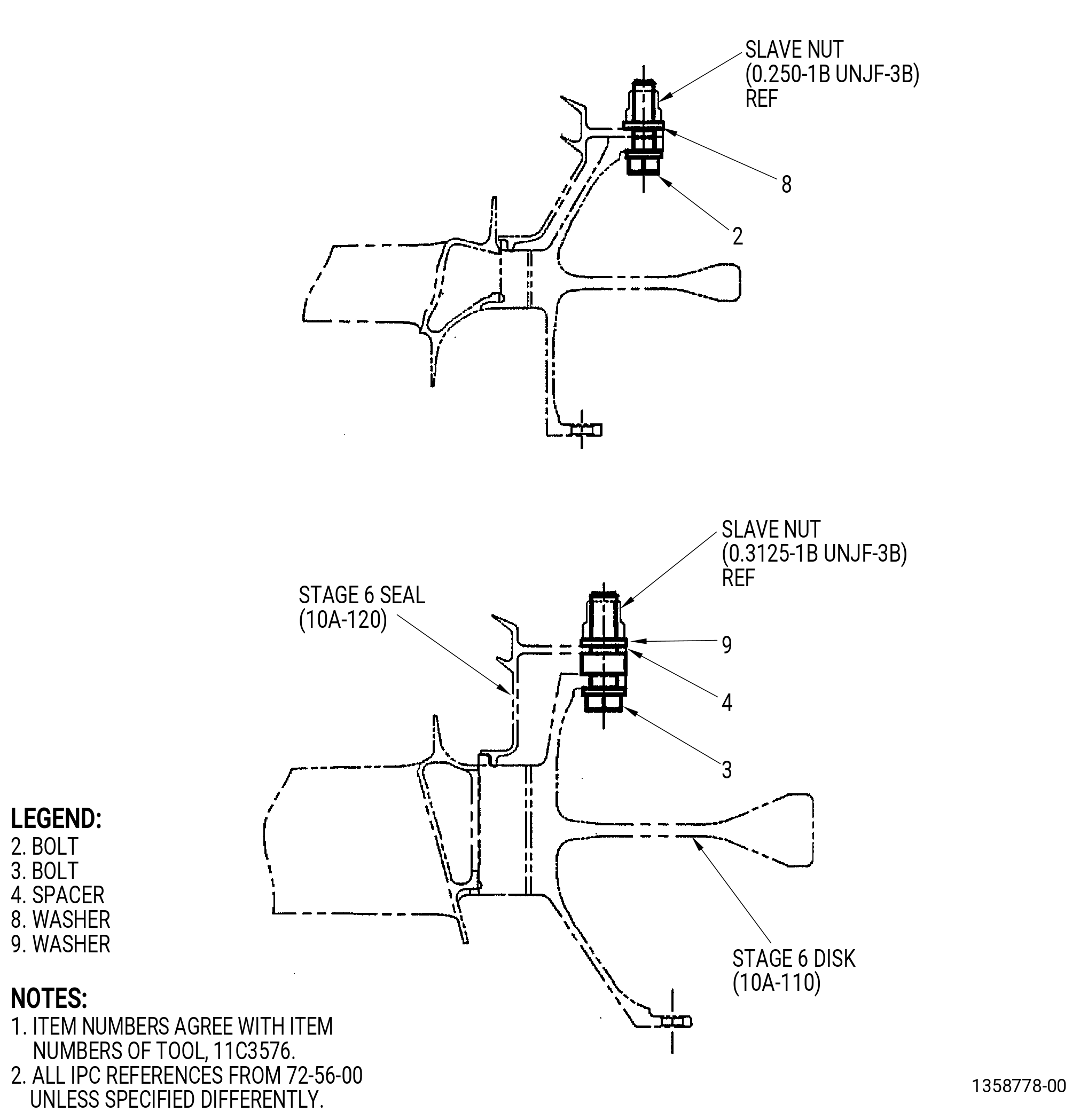
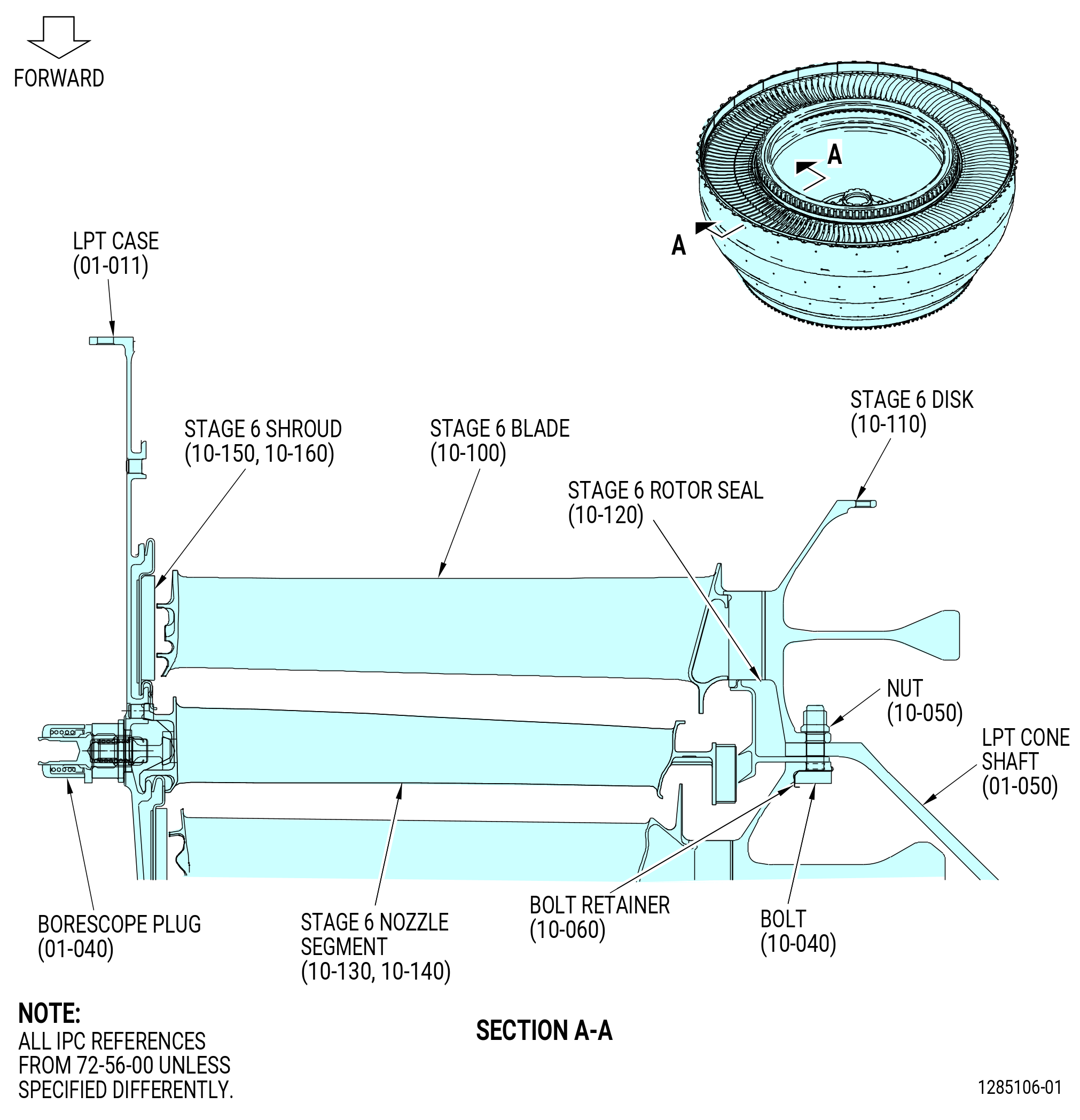
| F. | Assemble and balance the stage 6 disk (10-110), the stage 6 blades (10-100), and the LPT rotor stage 6 seal (stage 6 rotor seal) (10-120) as follows. Refer to Figure 1011. |
| (1) | Put the stage 6 rotor seal on the stage 6 disk and align the boltholes. |
| CAUTION: |
|
| (2) | Install the four bolts (item 3) and the spacers (item 4) of the 11C3576 dummy bolt/spacer and the 0.3125-24UNJF-3B slave nuts at four locations in equal spaces on the stage 6 disk and the stage 6 rotor seal. Tighten the slave nuts, but do not torque the slave nuts. Refer to Figure 1007. |
| (3) | If necessary, install the balance adapter onto the balance machine. |
| Subtask 72-56-00-440-276 |
| (4) | Prepare the 11C3542 LPT disk lift/turn fixture to lift the stage 6 disk (10-110). Refer to Figure 1003 and do as follows: |
| (a) | Install the lift cap (item 43) onto the spider (item 42) and insert the ball-lock pin (item 24). |
| (b) | Install the stage 6 foot (item 99) at three locations into the lift bars (item 46) and attach with the ball-lock pins (item 54). |
| NOTE: |
|
| (c) | Install the lift bars (item 46) at three locations into the spider (item 42) and attach ball-lock pins (item 54). Keep one lift bar inward, not attached to the spider, for the lift and turn fixture can be attached to the disk. |
| Subtask 72-56-00-440-277 |
| (5) | Attach the 11C3542 LPT disk lift/turn fixture to the stage 6 disk (10-110). Refer to Figure 1003 and do as follows: |
| (a) | Attach the lift arm (item 45) to the lift cap (item 43) with the ball-lock pin (item 25). |
| (b) | Attach a hoist to the lift arm (item 45). |
| WARNING: |
|
| CAUTION: |
|
| (c) | Carefully lift the 11C3542 LPT disk lift/turn fixture and lower it into the center of the stage 6 disk. |
| (d) | While you lower the fixture, put the foot (item 99) at two locations into the stage 6 disk. |
| (e) | Extend the third lift bar (item 46) outward and put the foot (item 99) into the stage 6 disk. |
| (f) | Attach the third lift bar (item 46) to the spider (item 42) with the ball-lock pin (item 54). |
| (g) | Make sure that the foot (item 99) at three locations engages the stage 6 disk. If not, make sure that you have installed the correct foot (item 99) for the stage 6 disk. |
| (6) | Lift the stage 6 disk (10-110) and put it, aft end down, on the balance machine. |
| (a) | If the disk is not in the correct position, turn the disk over. Refer to Subtask 72-56-00-440-264 (paragraph 3.A.(4)). |
| Subtask 72-56-00-440-278 |
| (7) | Remove the 11C3542 LPT disk lift/turn fixture from the stage 6 disk (10-110). Refer to Figure 1003 and do as follows: |
| (a) | Remove the ball-lock pins (item 22) from the spider (item 42) at one location. |
| (b) | Retract the lift arm (item 46) at one location to the inward position. |
| CAUTION: |
|
| (c) | While you carefully lift the 11C3542 LPT disk lift/turn fixture, slide the foot (item 99) at two locations from the stage 6 disk. |
| (d) | Put the 11C3542 LPT disk lift/turn fixture in a safe location. |
| Subtask 72-56-00-440-086 |
| CAUTION: |
|
| (8) | Attach the stage 6 disk and the stage 6 seal to the balance machine. |
| NOTE: |
|
| (9) | Set the balance machine to balance the stage 6 disk. Record the stage 6 disk and (FLA), weight (grams), and rpm. Refer to the balance machine manufacturer's instructions. |
| (a) | The correct R is 26.142 inches (664.00 mm). |
| (b) | The minimum speed is 600 rpm. |
| (10) | Put a mark with a C05-003 pen at the TVCL on the forward side of the stage 6 disk. |
| (11) | Moment weigh and plot the stage 6 blades (10-100) (SIN 930A6) with the 9446M61 balance program or by blade mapping. Number all the blades with a C05-003 pen on the inner dovetail of the blade. |
| (12) | Remove the stage 6 disk and the stage 6 seal from the balance machine. |
| (13) | Attach the 11C3542 LPT disk lift/turn fixture to the stage 6 disk. Refer to Subtask 72-56-00-440-277 (paragraph 3.F.(5)). |
| WARNING: |
|
| (14) | Lift the stage 6 disk and put it, aft end down, on the 11C3528 rotary table. Refer to Figure 1004. |
| (15) | Remove the 11C3542 LPT disk lift/turn fixture from the stage 6 disk. Refer to Subtask 72-56-00-440-278 (paragraph 3.F.(7)). |
| CAUTION: |
|
| (16) | Remove the 0.3125-24UNJF-3B slave nuts and the bolts (item 3) of the 11C3576 dummy bolt/spacer. Refer to Figure 1007. |
| (17) | Remove the stage 6 rotor seal from the stage 6 disk. |
| Subtask 72-56-00-640-011 |
| CAUTION: |
|
| (18) | Apply C02-033 lubricant to the dovetails and the tip shroud interlock faces of the stage 6 blades (10-100). |
| Subtask 72-56-00-440-115 |
| (19) | Put the stage 6 blades (10-100), with the leading edge up, on the stage 6 disk (10-110). Align the blade dovetail with the disk dovetail slot. |
| (20) | Lower the stage 6 blades until the dovetails touch the stage 6 disk. Make sure that the blade dovetails are aligned with the disk dovetail slots. |
| CAUTION: |
|
| CAUTION: |
|
| CAUTION: |
|
| (21) | Tap the dovetails of the stage 6 blades with a non-metallic tool. Continue to tap the stage 6 blades until they are fully installed into the stage 6 disk. |
| (22) | Make sure that the blade tip shroud interlock surface has positive contact. |
| Subtask 72-56-00-640-012 |
| (23) | Apply C02-058 graphite to the threads and washer faces of the four bolts (item 3) and the spacers (item 4) of the 11C3576 dummy bolt/spacer and the 0.3125-24UNJF-3B slave nuts. Refer to Figure 1007. |
| NOTE: |
|
| Subtask 72-56-00-440-087 |
| (24) | Put the stage 6 rotor seal (10-120) on the stage 6 disk (10-110) and align with the holes in the stage 6 disk. Refer Figure 1011. |
| (25) | Install the four bolts (item 3) and spacers (item 4) of the 11C3576 dummy bolt/spacer, and the 0.3125-24UNJF-3B slave nuts in equal spaces on the stage 6 disk and the stage 6 rotor seal. |
| CAUTION: |
|
| (26) | Torque the slave nuts to 78-91 lb in. (8.8-10.3 N.m). Use the wrench (item 3) of the 11C3576 dummy bolt/spacer to turn and tighten the nut. Refer to Figure 1007. |
| NOTE: |
|
| (27) | Remove any lubricant that remains with a clean C10-182 cloth. |
| (28) | Put a mark with a C05-003 pen at the location of the four bolts (item 3) of the 11C3576 dummy bolt/spacer on the stage 6 rotor seal and the stage 6 disk. Refer to Figure 1007. |
| (29) | Attach the 11C3542 LPT disk lift/turn fixture to the stage 6 disk and blade assembly. Refer to Subtask 72-56-00-440-277 (paragraph 3.F.(5)). |
| WARNING: |
|
| (30) | Lift and install the stage 6 disk and blade assembly, forward side down, on the balance machine. Refer to the manufacturer's instructions for installation. |
| (31) | Remove the 11C3542 LPT disk lift/turn fixture from the stage 6 disk and blade assembly. Refer to Subtask 72-56-00-440-278 (paragraph 3.F.(7)). |
| (32) | Refer to the manufacturer's instructions to balance the stage 6 disk (10-110) and blade assembly (10-100). |
| WARNING: |
|
| (a) | Turn the stage 6 disk and blade assembly CCW, ALF, at no less than 600 rpm. |
| (b) | The correct R is 26.142 inches (664.00 mm). |
| (c) | Do not add or remove any material to balance. |
| (d) | Put a mark with aC05-003 pen at the dovetail slot of the heavy-angle (area of unbalance) and the light-angle. |
| NOTE: |
|
| (e) | Disengage the stage 6 disk and blade assembly from the balance machine. Refer to manufacturer's instructions for removal. |
| (f) | If the unbalance of the stage 6 disk and blade assembly is more than 105 gram-inches (2667 grams-mm), move the stage 6 disk and blade assembly to the 11C3528 rotary table and arrange the stage 6 blades to bring the unbalance within limits. Refer to the manufacturer's instructions to balance the stage 6 disk and blade assembly until the unbalance of the stage 6 disk and blade assembly is less than 105 gram-inches (2667 grams-mm). |
| (33) | Attach the 11C3542 LPT disk lift/turn fixture to the balanced stage 6 disk (10-110) and blade assembly (10-100). Refer to Subtask 72-56-00-440-277 (paragraph 3.F.(5)). |
| WARNING: |
|
| (34) | Lift the stage 6 disk and blade assembly from the balance machine and put the assembly in a safe location. |
| (35) | Remove the 11C3542 LPT disk lift/turn fixture from the stage 6 disk. Refer to Subtask 72-56-00-440-278 (paragraph 3.F.(7)). |
| Subtask 72-56-00-440-091 |
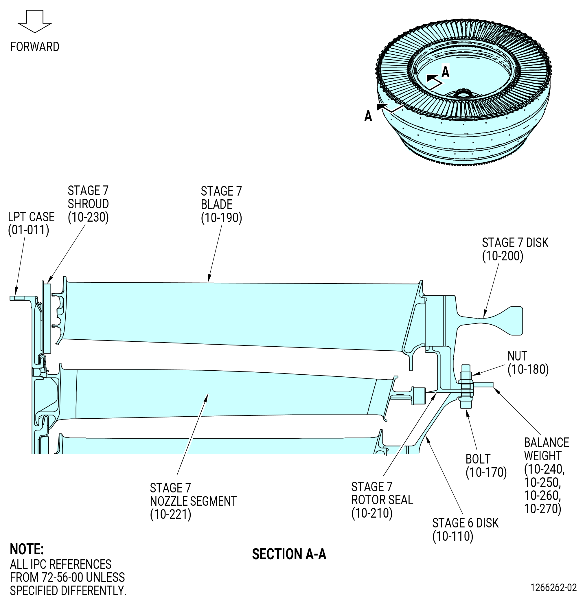
| G. | Assemble and balance the LPT rotor stage 7 disk (stage 7 disk) (10-200), the LPT stage 7 blades (stage 7 blade) (10-190), and the LPT rotor stage 7 seal (stage 7 rotor seal) (10-210) as follows. Refer to Figure 1012. |
| (1) | Prepare the 11C3542 LPT disk lift/turn fixture to lift the stage 7 disk. Refer to Figure 1003 and do as follows: |
| (a) | Install the lift cap (item 43) onto the spider (42) and insert the ball-lock pin (item 24). |
| (b) | Install the stage 7 foot (item 100) at three locations into the lift bars (item 46) and attach with the ball-lock pins (item 54). |
| NOTE: |
|
| (c) | Install the lift bars (item 46) at three locations into the spider (item 42) and attach ball-lock pins (item 54). Keep one lift bar inward, not attached to the spider, for the 11C3542 LPT disk lift/turn fixture can be attached to the disk. |
| Subtask 72-56-00-440-093 |
| (2) | Attach the 11C3542 LPT disk lift/turn fixture to the stage 7 disk (10-200). Refer to Figure 1004 and do as follows: |
| (a) | Attach the lift arm (item 45) to the lift cap (item 43) with the ball-lock pin (item 25). |
| (b) | Attach a hoist to the lift arm (item 45). |
| WARNING: |
|
| CAUTION: |
|
| (c) | Carefully lift the 11C3542 LPT disk lift/turn fixture and lower it into the center of the stage 7 disk. |
| (d) | While you lower the fixture, put the foot (item 100) at two locations into the stage 7 disk. |
| (e) | Extend the third lift bar (item 46) outward and put the foot (item 100) into the stage 7 disk. |
| (f) | Attach the third lift bar (item 46) to the spider (item 42) with the ball-lock pin (item 22). |
| (g) | Make sure that the foot (item 100) at three locations engages the stage 7 disk. If not, make sure that you have installed the correct foot (item 100) for the stage 7 disk. |
| (3) | Put the stage 7 rotor seal (10-210) on the balance adapter with the forward flange down and attached. |
| (a) | If necessary, install the balance adapter onto the balance machine. |
| (4) | Lift the stage 7 disk (10-200) and lower, forward end down, onto the stage 7 rotor seal. |
| (a) | If the disk is not in the correct position, turn the disk over. Refer to Subtask 72-56-00-440-264 (paragraph 3.A.(4)). |
| Subtask 72-56-00-440-279 |
| (5) | Remove the 11C3542 LPT disk lift/turn fixture from the stage 7 disk (10-200). Refer to Figure 1004 and do as follows: |
| (a) | Remove the ball-lock pins (item 46) from the spider (item 42) at one location. |
| (b) | Retract the lift arms (item 46) at one location to the inward location. |
| CAUTION: |
|
| (c) | While you carefully lift the 11C3542 LPT disk lift/turn fixture, slide the foot (item 100) at two locations from the stage 6 disk. Put the hoist and the lift arm in a safe location. |
| (d) | Put the 11C3542 LPT disk lift/turn fixture in a safe location. |
| CAUTION: |
|
| (6) | Attach the stage 7 disk (10-200) and the stage 7 rotor seal (10-210) to the balance adapter. |
| (7) | Set the balance machine to balance the stage 7 disk (10-200) and the stage 7 rotor seal (10-210). Record the stage 7 disk and (FLA), weight (grams), and rpm. Refer to the manufacturer's instructions. |
| (a) | The correct R is 25.394 inches (645.00 mm). |
| (b) | The minimum speed is 600 rpm. |
| (8) | Put a mark with a C05-003 pen at the TVCL on the forward side of the stage 7 disk (10-200). |
| (9) | Moment weigh and plot the stage 7 blades (10-190) (SIN 930A7) with the 9446M61 balance program or by blade mapping. Number all the blades with a C05-003 pen on the inner dovetail of the blade. |
| (10) | Remove the stage 7 disk and the stage 7 rotor seal from the balance adapter. |
| (11) | Attach the 11C3542 LPT disk lift/turn fixture to the stage 7 disk. Refer to Subtask 72-56-00-440-093 (paragraph 3.G.(2)). |
| (12) | Lift the stage 7 disk and put it, aft end down, on the 11C3528 rotary table. Refer to Figure 1004. |
| (a) | Turn the disk over for the aft end is down. Refer to Subtask 72-56-00-440-264 (paragraph 3.A.(4)). |
| (13) | Remove the 11C3542 LPT disk lift/turn fixture from the stage 7 disk. Refer to Subtask 72-56-00-440-279 (paragraph 3.G.(5)). |
| CAUTION: |
|
| (14) | Apply C02-033 lubricant to the dovetails and the tip shroud interlock faces of the stage 7 blades (10-190). |
| (15) | Put the stage 7 blades, with the leading edge up, on the stage 7 disk (10-200). Align the blade dovetail with the disk dovetail slot. |
| (16) | Continue to put the stage 7 blades on the stage 7 disk until the dovetails of the stage 7 blades touch the dovetail slots of the stage 7 disk. Make sure that the blade dovetails are aligned with the disk dovetail slots. |
| CAUTION: |
|
| CAUTION: |
|
| CAUTION: |
|
| (17) | Tap the dovetails of the stage 7 blades with a non-metallic tool until they are fully installed into the stage 7 disk. |
| (18) | Make sure that the blade tip shroud interlock surface has positive contact. |
| (19) | Attach the 11C3542 LPT disk lift/turn fixture to the stage 7 disk and blade assembly. Refer to Subtask 72-56-00-440-093 (paragraph 3.G.(2)). |
| (20) | Lift and install the stage 7 disk and blade assembly, forward side down, onto the balance adapter on the balance machine. Refer to the manufacturer's instructions for installation. |
| (a) | Turn the disk over and put the aft end down. Refer to Subtask 72-56-00-440-264 (paragraph 3.A.(4)). |
| (21) | Remove the 11C3542 LPT disk lift/turn fixture from the stage 7 disk and blade assembly. Refer to Subtask 72-56-00-440-279 (paragraph 3.G.(5)). |
| (22) | Refer to the balance machine manufacturer's instructions to balance the stage 7 disk and blade assembly. |
| WARNING: |
|
| (a) | Turn the stage 7 disk and blade assembly CCW, ALF, at no less than 600 rpm. |
| (b) | The correct R value is 25.394 inches (645.00 mm). |
| (c) | Do not add or remove any material to balance. |
| (d) | Put a mark with a C05-003 pen at the dovetail slot of the heavy-angle (area of unbalance) and the light-angle. |
| NOTE: |
|
| (e) | Disengage the stage 7 disk and blade assembly from the balance machine. Refer to the manufacturer's instructions for removal. |
| (f) | If the unbalance of the stage 7 disk and blade assembly is more than 105 gram-inches (2667 grams-mm), move the stage 7 disk and blade assembly to the 11C3528 rotary table and arrange the stage 7 blades to bring the unbalance within limits. Refer to the manufacturer's instructions to balance the stage 7 disk and blade assembly until the unbalance of the stage 7 disk and blade assembly is less than 105 gram-inches (2667 grams-mm). |
| (23) | Attach the 11C3542 LPT disk lift/turn fixture to the balanced stage 7 disk (10-200) and stage 7 blades (10-190). Refer to Subtask 72-56-00-440-093 (paragraph 3.G.(2)). |
| WARNING: |
|
| (24) | Lift the stage 7 disk and blade assembly from the balance machine and put the assembly in a safe location. |
| (25) | Remove the 11C3542 LPT disk lift/turn fixture from the stage 7 disk. Refer to Subtask 72-56-440-279 (paragraph 3.G.(5)). |
| Subtask 72-56-00-440-010 |
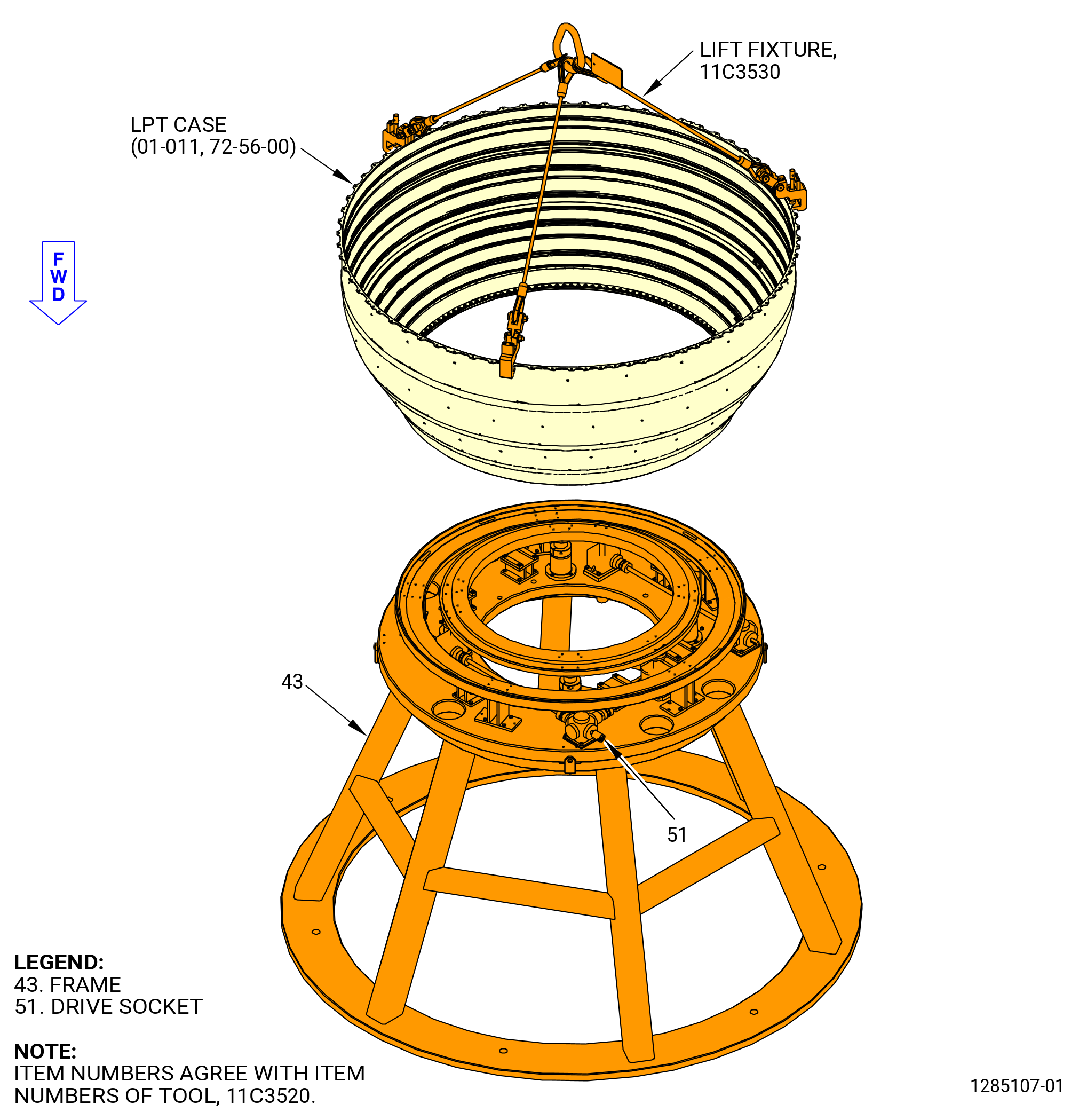
| H. | Install the LPT turbine case (LPT case) (01-011) on the 11C3520 buildup stand as follows: |
| (1) | Attach the 11C3530 lift fixture to the LPT case as follows. Refer to Figure 1013. |
| (a) | Attach the sling assembly (item 12) to an overhead hoist hook. |
| (b) | Turn the pin (item 4) counterclockwise (CCW) to pull the pin from the hook blocks (item 10). |
| CAUTION: |
|
| (c) | Attach the hook blocks (item 10) at three locations to the aft outer flange of the LPT case. You must turn the pin (item 4) CW to attach the hook blocks (item 10) to the LPT case. |
| WARNING: |
|
| (2) | Lift the LPT case and put it on of the 11C3520 buildup stand as follows. Refer to Figure 1014. |
| (a) | Align the forward flange of the LPT case to the plate (item 4) and lower the LPT case onto the 11C3520 buildup stand. |
| (b) | Remove the 11C3530 lift fixture from the LPT case. |
| (3) | Put the LPT case into position on the 11C3520 buildup stand. Refer to Figure 1014. |
| Subtask 72-56-00-440-011 |
| I. | Assemble and install the stage 1 shrouds (05-060) and the stage 1 shroud (05-060) on the LPT case (01-011) as follows: |
| (1) | Apply C01-027 synthetic adhesive, C02-033 lubricant , C10-109 utility wax, or C10-154 beeswax into the spline seal slots on one end of each stage 1 shroud. Make sure that the wax is applied to the same end of each stage 1 shroud. Refer to Figure 1015. |
| (2) | Install the seals (05-090) (SIN 935W1) and (05-100) (SIN 935W8) into the waxed slots of each stage 1 shroud. |
| (3) | The stage 1 shroud is installed at the TVCL (12:00 o'clock) on the offset nut of the LPT case. Make sure that the forward taps are offset of the shank nut on the LPT case. |
| (4) | Install the stage 1 shrouds (05-060, 05-070) as follows: |
| (a) | Align the forward lip of the stage 1 shroud with the groove in the LPT case. |
| (b) | Align the tab of the stage 1 shroud with the head of the first shouldered stud in the LPT case, CCW of the top vertical center line, ALF. |
| (c) | Install the stage 1 shroud into the LPT case. |
| (d) | Continue this procedure to install each remaining stage 1 shroud, adjacent to the previous stage 1 shroud, into the LPT case. |
| 1 | Make sure that the seals (05-090) (SIN 935W1) and (05-100) (SIN 935W8) are fully engaged as each adjacent stage 1 shroud is installed. |
| NOTE: |
|
| (e) | Tap the aft end of the stage 1 shrouds axially forward and radially outward to Make sure that the stage 1 shrouds are completely installed into the LPT case. |
| CAUTION: |
|
| (5) | Install the stage 1 shroud clip (shroud clip) (05-080) (SIN 935B7) on the stage 1 shrouds (05-060, 05-070) as follows: |
| (a) | Lubricate the shroud clip (05-080) with C02-033 lubricant. |
| (b) | Put a retaining clip between the tabs on each stage 1 shroud. Put the retaining clips in the LPT case stage 1 aft groove and on the aft lip of the stage 1 shroud. |
| 1 | Make sure that the curve of the retaining clips align with the curve of the stage 1 shroud. |
| (c) | Put a wood or phenolic block along the length of the retaining clips. Tap the blocks as necessary to install the retaining clips. |
| 1 | Make sure that the retaining clips are completely installed against the stage 1 shroud and the LPT case. |
| Subtask 72-56-00-440-103 |
| J. | Install the stage 1 disk (05-020) and blade assembly, forward end down, on the 11C3520 buildup stand as follows: |
| (1) | If the stage 1 disk and blade assembly is not in the correct position, use the 11C3542 lift and turn fixture to turn the stage 1 disk and blade assembly over. Refer to Figure 1003 and do as follows: |
| CAUTION: |
|
| (a) | Prepare the 11C3542 LPT disk lift/turn fixture to lift the stage 1 disk (05-020). Refer to Subtask 72-56-00-440-265 (paragraph 3.A.(2)). |
| (b) | Attach the 11C3542 LPT disk lift/turn fixture to the stage 1 disk (05-020). Refer to Subtask 72-56-00-440-189 (paragraph 3.A.(3)). |
| WARNING: |
|
| (c) | Lift the stage 1 disk and blade assembly and rotate to put the forward end down, on a safe work table. Refer to Subtask 72-56-00-440-264 (paragraph 3.A.(4)). |
| (d) | Remove the 11C3542 LPT disk lift/turn fixture from the stage 1 disk (05-020) and blade assembly. Refer to Subtask 72-56-00-440-166 (paragraph 3.A.(6)). |
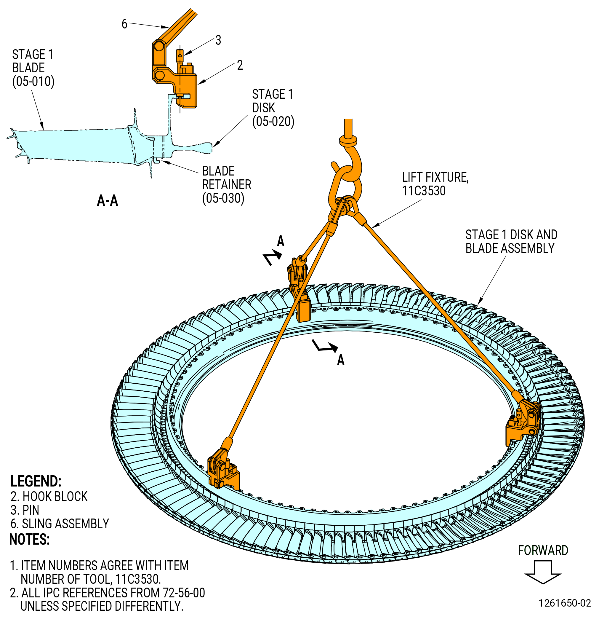
| (2) | Attach the 11C3530 lift fixture to the stage 1 disk flange at three equally spaced bolthole locations. Refer to Figure 1016. |
| (3) | Attach a hoist to the 11C3530 lift fixture. |
| WARNING: |
|
| (4) | Lift and install the stage 1 disk and blade assembly into the LPT case (01-011). |
| NOTE: |
|
| NOTE: |
|
| (5) | Remove the 11C3530 lift fixture from the stage 1 disk. Put the lift fixture in a safe location. |
| Subtask 72-56-00-440-105 |
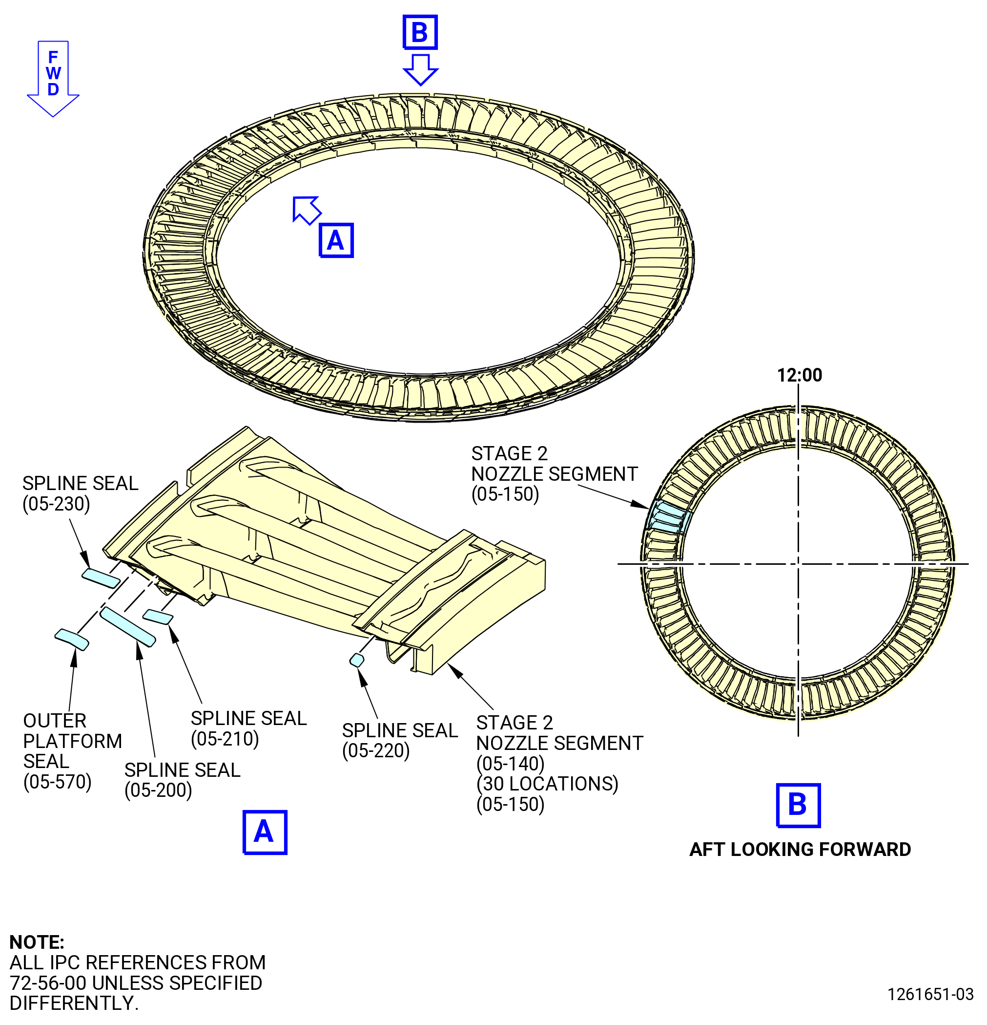
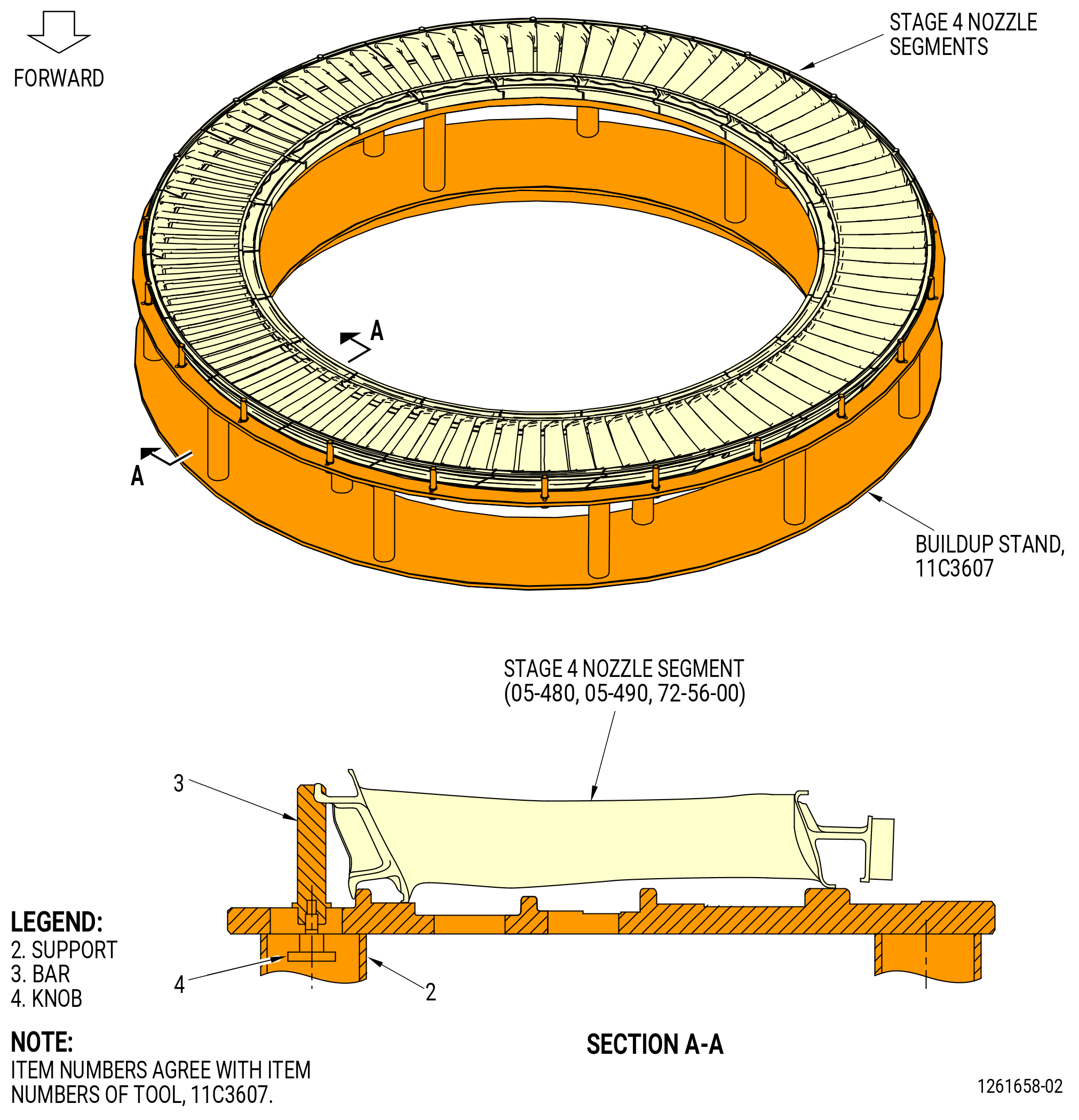
| K. | Install the stage 2 nozzle segments (05-140, 05-150) in the LPT case (01-011) as follows. Refer to Figure 1006. |
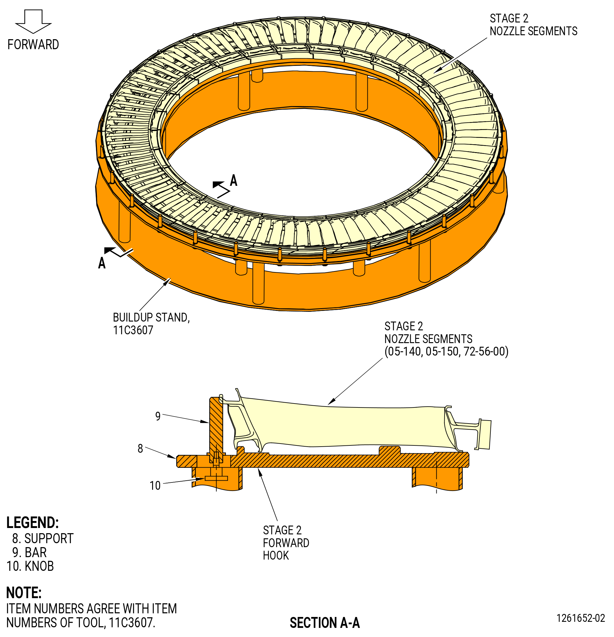
| (1) | Put the 11C3607 buildup stand on a safe work table. |
| (2) | Install the LPT stage 2 nozzle segments on the 11C3607 buildup stand as follows: |
| (a) | Apply C01-027 synthetic adhesive, C02-033 lubricant , C10-109 utility wax, or C10-154 beeswax into the inner and outer spline seal slots on one end of each LPT stage 2 nozzle segment. Make sure that the wax is applied to the same end of each LPT stage 2 nozzle segment. |
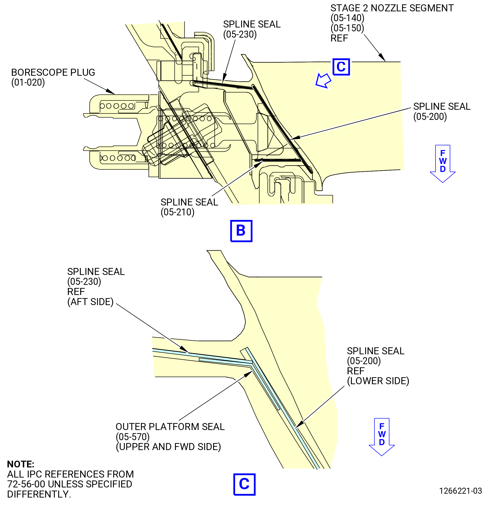
| (b) | Install the spline seals (outer) (05-200) (SIN 935Y0), (05-210) (SIN 935Y1), and (05-230) (SIN 935Y3), the outer platform seal (05-570) (SIN 935YE), and the spline seals (inner) (05-220) (SIN 935Y2) into each LPT stage 2 nozzle segment as follows. Refer to Figure 1017. |
| 1 | Make sure that the slant of the spline seals match the slant of the LPT stage 2 nozzle segment and adjacent seal. |
| 2 | Put the outer platform seal (05-570) (SIN 935YE) on the upper and forward side of the spline seals (05-200) (SIN 935Y0) and (05-230) (SIN 935Y3). |
| (c) | Install the LPT stage 2 nozzle segment (05-140, 05-150), aft end up, at the stage 2 borescope hole on the 11C3607 buildup stand with the aft end up. Refer to Figure 1018. |
| (d) | Continue this procedure to install all the stage 2 nozzle segments (05-140, 05-150), adjacent to the previous LPT stage 2 nozzle segment, into the 11C3607 buildup stand. Make sure that the spline seals are fully engaged as each adjacent LPT stage 2 nozzle segment is installed. |
| (e) | Rotate the knob (item 10) to put the bar (item 9) on the nozzle segment. |
| Subtask 72-56-00-440-149 |
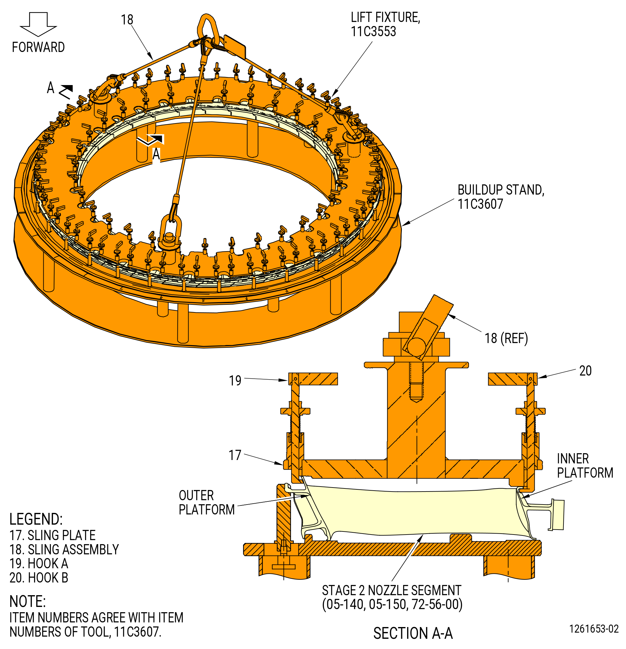
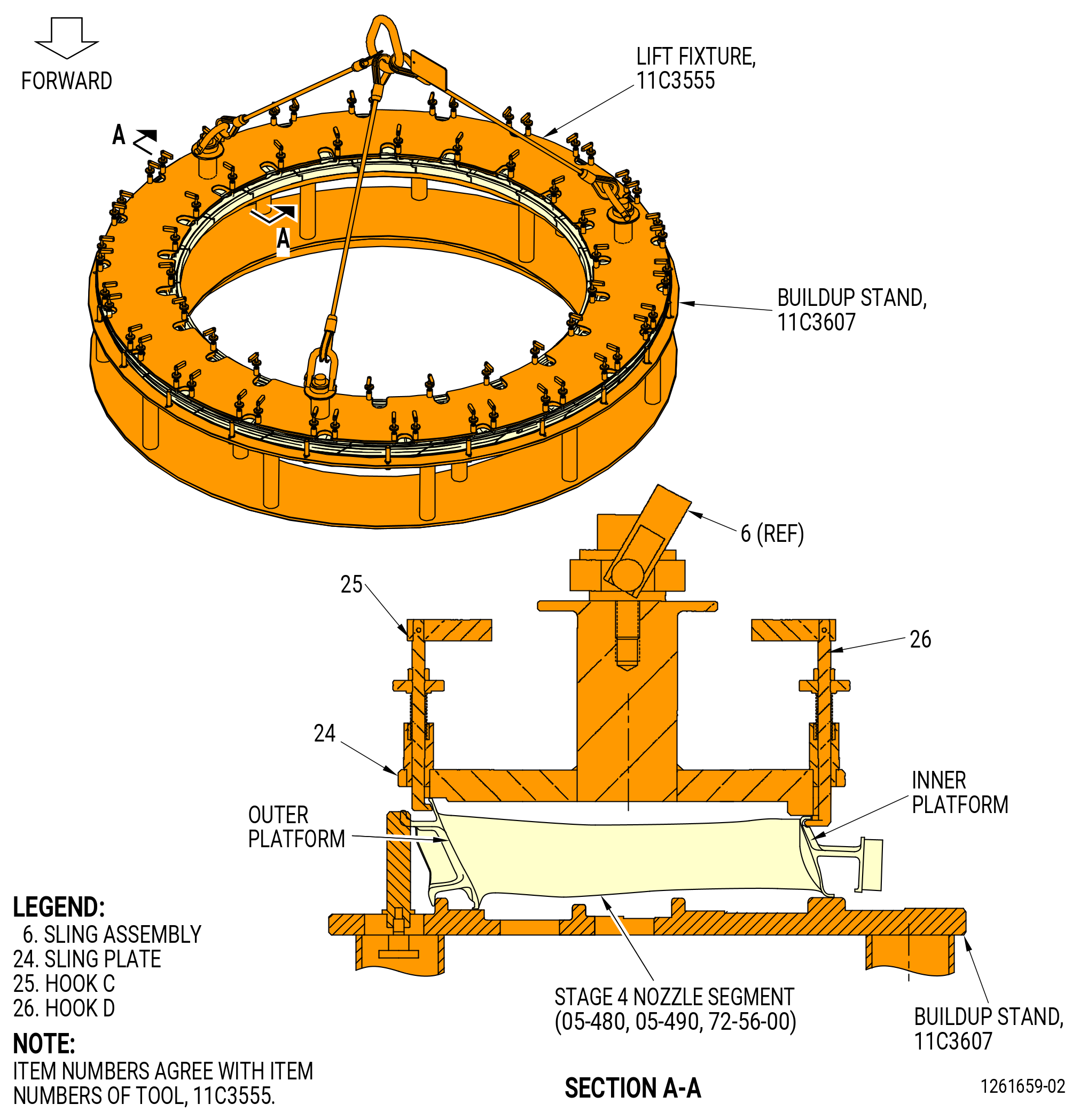
| (3) | Attach the 11C3553 lift fixture to the LPT stage 2 nozzle segments as follows. Refer to Figure 1019. |
| WARNING: |
|
| (a) | Lift the sling plate (item 17) and put it into position on the LPT stage 2 nozzle segments. |
| (b) | Make sure that the TOP vertical marks of the 11C3553 lift fixture and the 11C3607 buildup stand are aligned. |
| NOTE: |
|
| (c) | Turn hook A (item 19) at 62 locations to the LOCK position. Make sure that the hook is against the nozzle segment inner platform. |
| (d) | Turn hook B (item 20) at 31 locations to the LOCK position. Make sure the hook is under the nozzle segment outer platform. |
| (e) | Attach a hoist to the sling assembly (item 18). |
| (4) | Lift the LPT stage 2 nozzle segments and put them into position in the LPT case. |
| (5) | Make sure that the top vertical positions of the 11C3553 lift fixture and the LPT case are aligned. |
| (6) | Make sure that the stage 2 nozzle segment (05-140, 05-150) is aligned with the borescope hole in the LPT case. |
| CAUTION: |
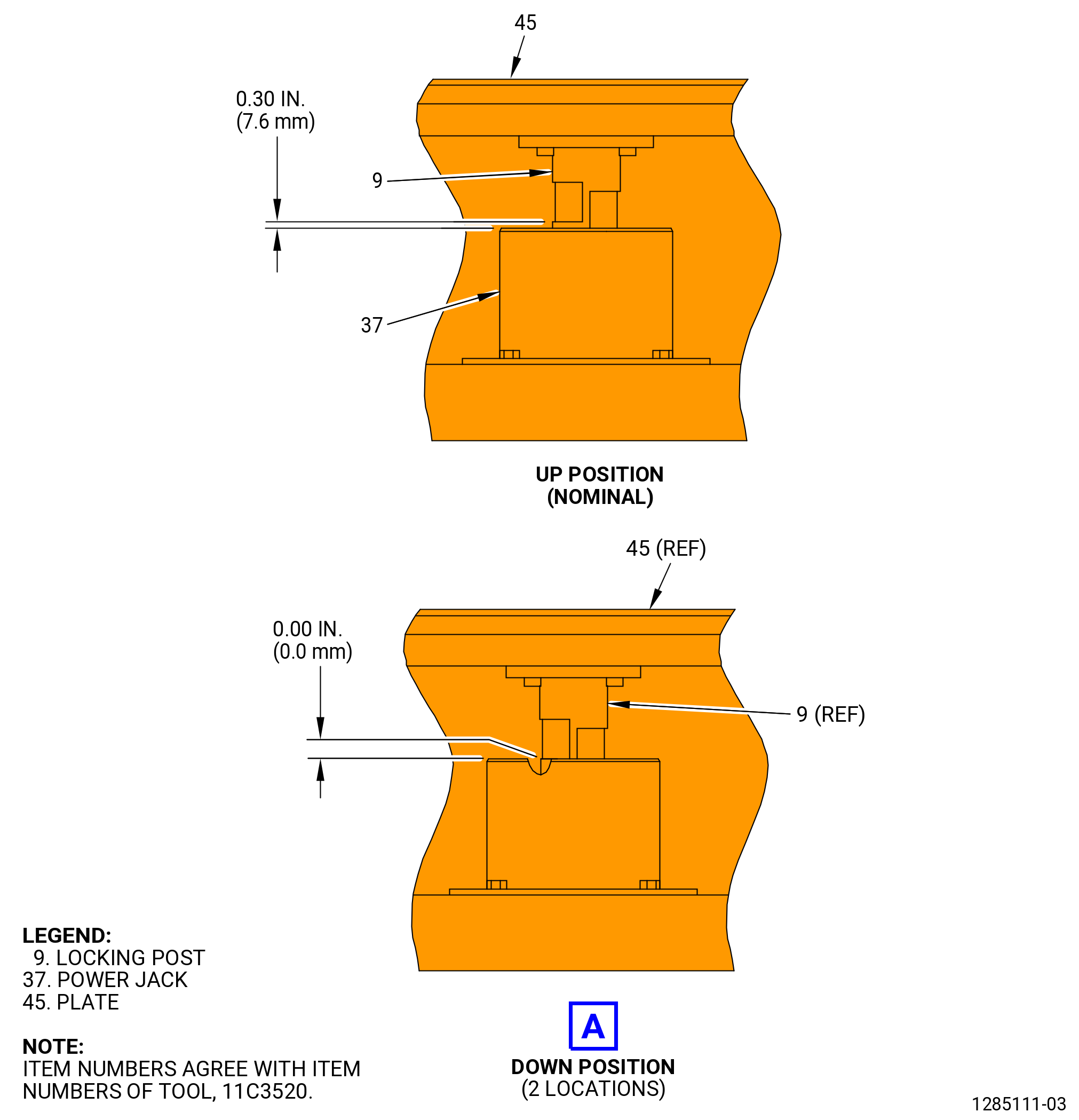
|
| (7) | Turn the drive socket (item 51) of the 11C3520 buildup stand to move the LPT rotor 0.295 inch (7.49 mm) forward of the NOMINAL position to help to install the LPT stage 2 nozzle segments. |
| (8) | Turn the hook B (item 20) of the 11C3553 lift fixture off the LOCK position at 31 locations. Make sure that the hook is inward away from the nozzle segment. |
| (9) | Turn the hook A (item 19) off the LOCK position at 62 locations. Make sure that the hook is outward away from the nozzle segment. |
| WARNING: |
|
| (10) | Lift the 11C3553 lift fixture out and away from the LPT case. Put the hoist and the fixture in a safe location. |
| (11) | Tap the LPT stage 2 nozzle segments with a mallet and a nylon bar, as necessary, to install the LPT stage 2 nozzle segments into the LPT case. |
| CAUTION: |
|
| (12) | Turn the drive socket (item 51) of the 11C3520 buildup stand to move the LPT rotor to the NOMINAL position after the LPT stage 2 nozzle segments are installed. |
| (13) | Make sure that all of the spline seals are in the correct positions. |
| (14) | Make sure that the nozzle segments are seated radially outward and axially aft against the stops in the aft fan case (01-011). |
| (a) | Tap the LPT stage 2 nozzle segments with a mallet and a nylon bar, as necessary, to install the LPT stage 2 nozzle segments into the LPT case. |
| Subtask 72-56-00-220-016 |
| L. | Do a visual inspection of the borescope plugs and ports. Refer to TASK 72-00-00-800-804 (72-00-00, SPECIAL PROCEDURE 004) (paragraph 5.A. and 5.B.). |
| Subtask 72-56-00-440-170 |
| M. | Install the borescope plug (01-020) on the LPT case (01-011) at the stage 2 nozzle segment as follows. Refer to Figure 1006. |
| Subtask 72-56-00-640-028 |
| (1) | Apply C02-071 anti-seize compound to the threads and the friction surfaces of the borescope plug that touch the LPT case. |
| (2) | Install the borescope plug in the correct position on the LPT case. |
| (3) | Torque the borescope plug to 150-168 lb in. (17-19 N.m). |
| (4) | Torque the borescope plug again to 150-168 lb in. (17-19 N.m). |
| (5) | After the plug has been torqued, perform a visual inspection of the plug and make sure that the locking feature is fully engaged with the lug on the borescope boss. Also make sure that the head of the borescope plug is fully seated against the borescope boss. If one of the two conditions are not met, the ratcheting feature of the plug can be seized or locked. Apply a penetrating oil directly in between the locking ring and the head of the plug. Re-apply torque to the plug until the plug begins to rotate freely. Tighten the plug from 150 to 168 lb in. (16.9 to 18.9 Nm). Do the visual inspection again before proceeding. If the conditions above cannot be met, replace the plug. Refer to Figure 1030. |
| Subtask 72-56-00-440-107 |
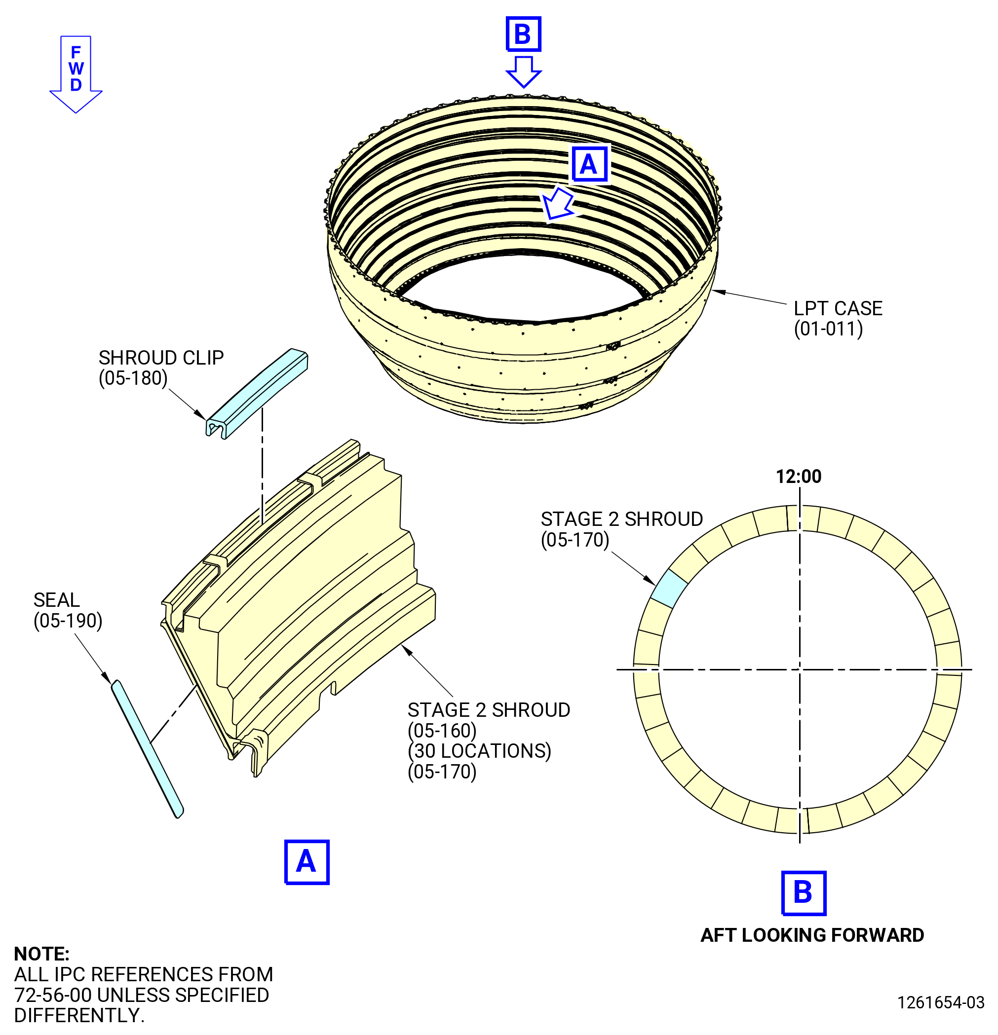
| N. | Assemble and install the stage 2 shrouds (05-160) and the stage 2 shroud with the offset slot (05-170) on the LPT case (01-011) as follows: |
| (1) | Apply C01-027 synthetic adhesive, C02-033 lubricant , or C10-154 beeswax into the spline seal slots on one end of each stage 2 shroud. Make sure that the wax is applied to the same end of each stage 2 shroud. Refer to Figure 1020. |
| (2) | Install the seal (05-190) (SIN 935W2) into the waxed slot of each stage 2 shroud. |
| (3) | The stage 2 shroud with the offset slot (05-170) is installed at the 10:00 o'clock position (ALF). Make sure that the forward taps are offset of the shank nut on the LPT case. |
| (4) | Install the stage 2 shrouds (05-160, 05-170) as follows: |
| (a) | Align the forward lip of the stage 2 shroud with the groove in the LPT case. |
| (b) | Align the tab of the stage 2 shroud with the head of the first shouldered stud in the LPT case, CCW of the top vertical center line, ALF. |
| (c) | Install the stage 2 shroud into the LPT case. |
| (d) | Continue this procedure to install each remaining stage 2 shroud, adjacent to the previous stage 2 shroud, into the LPT case. |
| 1 | Make sure that the seals (05-190) (SIN 935W2) are fully engaged as each adjacent stage 2 shroud is installed. |
| NOTE: |
|
| (e) | Tap the aft end of the stage 2 shrouds axially forward and radially outward. Make sure that the stage 2 shrouds are completely installed into the LPT case. |
| CAUTION: |
|
| (5) | Install the stage 2 shroud clip (shroud clip) (05-180) (SIN 935B8) on the stage 2 shrouds (05-160, 05-170). Refer to Figure 1020 and do as follows: |
| (a) | Lubricate the shroud clip (05-180) with C02-033 lubricant. |
| Subtask 72-56-00-440-172 |
| (b) | Put a retaining clip between the tabs on each stage 2 shroud (05-160, 05-170). Put the retaining clips in the LPT case stage 2 aft groove and on the aft lip of the stage 2 shroud. |
| 1 | Make sure that the curve of the retaining clips align with the curve of the stage 2 shroud. |
| (c) | Put a wood or phenolic block along the length of the retaining clips. Tap the blocks as necessary to install the retaining clips. |
| 1 | Make sure that the retaining clips are completely installed against the stage 2 shroud and the LPT case. |
| Subtask 72-56-00-440-108 |
| O. | Install the stage 2 disk (05-120) and blade assembly on the stage 1 disk (05-020) as follows: |
| (1) | Remove the four slave nuts and four slave bolts from the stage 2 rotor seal (05-130) and the stage 2 disk. |
| (2) | Remove the stage 2 rotor seal from the stage 2 disk and put the stage 2 rotor seal, forward end down, on the stage 1 disk. Refer to Figure 1006. |
| (3) | Prepare the 11C3542 LPT disk lift/turn fixture to lift the stage 2 disk. Refer to Figure 1003 and Subtask 72-56-00-440-266 (paragraph 3.B.(4)). |
| (4) | Attach the 11C3542 LPT disk lift/turn fixture to the stage 2 disk. Refer to Figure 1003 and Subtask 72-56-00-440-267 (paragraph 3.B.(5)). |
| (5) | Attach a hoist to the 11C3542 LPT disk lift/turn fixture. |
| WARNING: |
|
| (6) | Lift the stage 2 disk and put it, forward end down, on the stage 2 rotor seal and the stage 1 disk. Align the match marks of the stage 2 disk with the stage rotor seal. Refer to Figure 1006. |
| NOTE: |
|
| (7) | Remove the 11C3542 LPT disk lift/turn fixture from the stage 2 disk. |
| (8) | Install the stage 2 disk on the stage 1 disk as follows. Refer to Figure 1006. |
| Subtask 72-56-00-640-015 |
| (a) | Apply C02-058 graphite to the threads and friction bearing surfaces of the bolts (05-040) and nuts (05-050). |
| NOTE: |
|
| Subtask 72-56-00-440-118 |
| (b) | Install the bolts (05-040) through the stage 1 disk, stage 2 rotor seal, and stage 2 disk. |
| (c) | Install the nuts (05-050) on the bolts. |
| CAUTION: |
|
| (d) | Torque the nuts at 10 locations to 65 lb in. (7.3 Nm) (at 75 percent of full torque) at equally-spaced positions in a criss-cross pattern around the circumference of the stage 2 disk. Use the wrench (item 2) of the 11C3560 nut wrench to hold the bolt. |
| (e) | Torque all the nuts to 78 to 91 lb in. (8.8 to 10.3 Nm) in a circumferential order. |
| (f) | Do a torque inspection of every bolt again in a circumferential order. |
| (g) | Do a visual inspection to make sure that the nuts are tightened correctly (to make sure that the bolts protrude from the nut). |
| Subtask 72-56-00-440-119 |
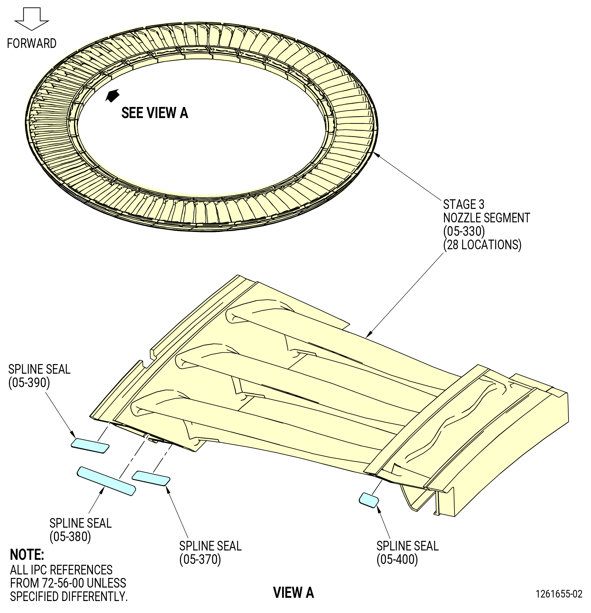
| P. | Install the stage 3 nozzle segments (05-330) in the LPT case (01-011) as follows. Refer to Figure 1008. |
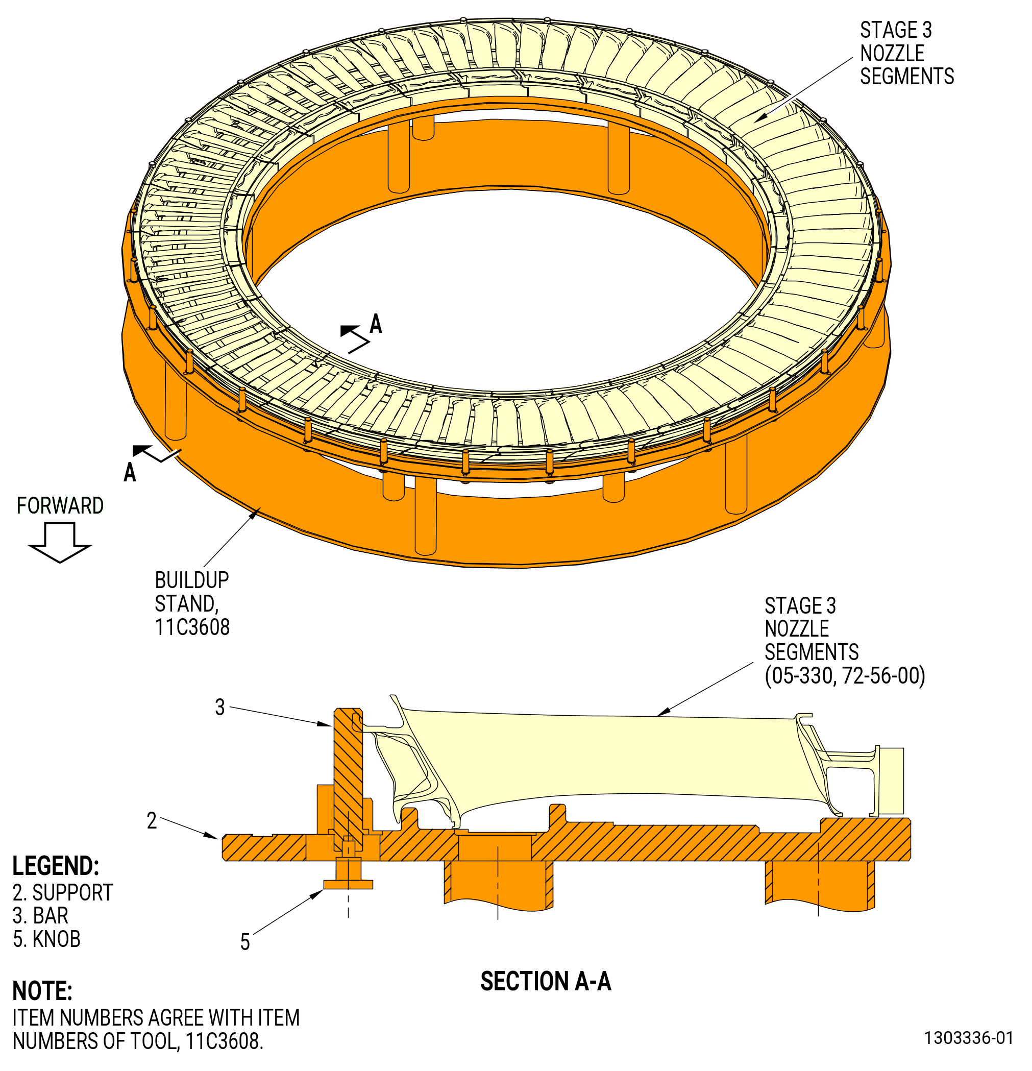
| (1) | Put the 11C3608 buildup stand on a safe work table. |
| (2) | Install the stage 3 nozzle segments (05-330) on the 11C3608 buildup stand as follows. Refer to Figure 1022. |
| (a) | Apply C01-027 synthetic adhesive, C02-033 lubricant , C10-109 utility wax, or C10-154 beeswax into the inner and outer spline seal slots on one end of each LPT stage 3 nozzle segment. Make sure that the wax is applied to the same end of each LPT stage 3 nozzle segment. |
| (b) | Install the spline seals (outer) (05-370) (SIN 935W7), (05-380) (SIN 935Y4), and (05-390) (SIN 935Y5), and the spline seal (inner) (05-400) (SIN 935Y6) into each LPT stage 3 nozzle segment. Refer to Figure 1021. |
| (c) | Make sure that the slant of the spline seals aligns with the slant of the LPT stage 3 nozzle segment and adjacent seal. |
| (d) | Continue this procedure to install all the stage 3 nozzle segments, adjacent to the previous LPT stage 3 nozzle segment, into the 11C3608 buildup stand. Make sure that the spline seals are fully engaged as each adjacent LPT stage 3 nozzle segment is installed. |
| (e) | Rotate the knob (item 10) to put the bar (item 9) on the LPT stage 3 nozzle segments. |
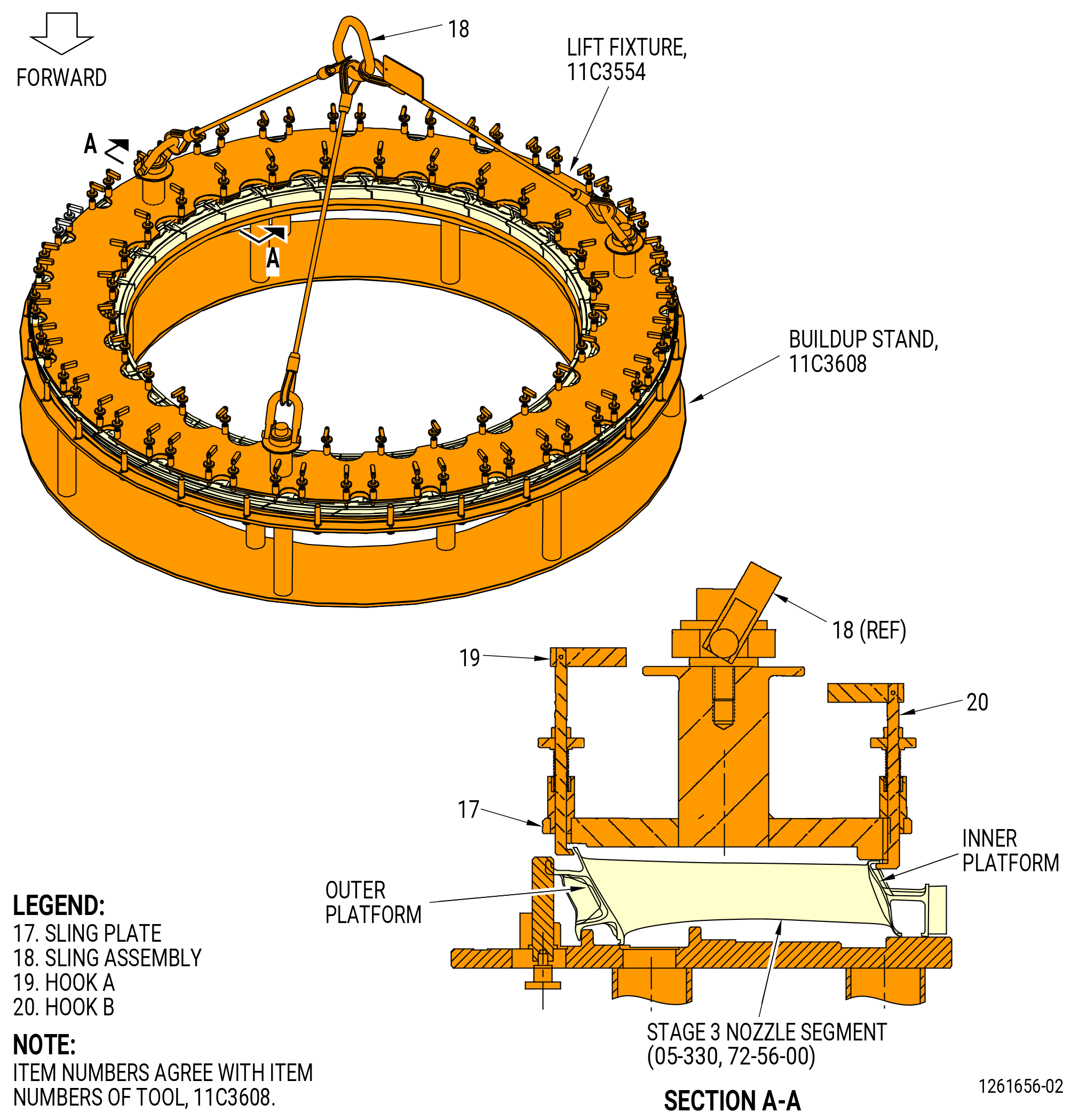
| (3) | Attach the 11C3554 lift fixture to the LPT stage 3 nozzle segments as follows. Refer to Figure 1023. |
| (a) | Attach a hoist to the sling assembly (item 18). |
| WARNING: |
|
| (b) | Lift the sling plate (item 17) and put it into position on the LPT stage 3 nozzle segments. |
| (c) | Make sure that the TOP vertical marks of the 11C3554 lift fixture and the 11C3608 buildup stand are aligned. |
| (d) | Turn hook A (item 19) at 56 locations to the LOCK position. Make sure that the hook is under the nozzle segment outer platform. |
| (e) | Turn hook B (item 20) at 28 locations to the LOCK position. Make sure that the hook is against the nozzle segment inner platform. |
| Subtask 72-56-00-440-150 |
| WARNING: |
|
| (4) | Lift the LPT stage 3 nozzle segments from the 11C3608 buildup stand and put them into position in the LPT case. Refer to Figure 1008. |
| (5) | Make sure that the top vertical positions of the 11C3554 lift fixture and the LPT case are aligned. |
| CAUTION: |
|
| (6) | Turn the drive socket (item 51) of the 11C3520 buildup stand to move the LPT rotor 0.295 inch (7.49 mm) forward of the NOMINAL position to help install the LPT stage 3 nozzle segments. |
| (7) | Turn the hook B (item 20) of the 11C3554 lift fixture off the LOCK positions at 28 locations. Make sure that the hook is inward away from the nozzle segment. |
| (8) | Turn hook A (item 19) at 56 locations off the LOCK position. Make sure that the hook is outward away from the nozzle segment. |
| WARNING: |
|
| (9) | Lift the 11C3554 lift fixture out and away from the LPT case. Put the hoist and the fixture in a safe location. |
| (10) | Tap the LPT stage 3 nozzle segments with a mallet and a nylon bar, as necessary, to install the LPT stage 3 nozzle segments into the LPT case. |
| (11) | Make sure that all of the spline seals are in the correct positions. |
| (12) | Make sure that the nozzle segments are seated radially outward and axially aft against the stops in the LPT case (01-011). |
| (a) | Tap the LPT stage 3 nozzle segments with a mallet and a nylon bar, as necessary, to install the LPT stage 3 nozzle segments into the LPT case. |
| CAUTION: |
|
| (13) | Turn the drive socket (item 51) of the 11C3520 buildup stand to move the LPT rotor to the NOMINAL position after the LPT stage 3 nozzle segments are installed. |
| Subtask 72-56-00-440-120 |
| Q. | Assemble and install the stage 3 shrouds (05-340) on the LPT case (01-011) as follows: |
| (1) | Apply C01-027 adhesive, C02-033 lubricant, or C10-154 beeswax into the spline seal slots on one end of each stage 3 shroud. Refer to Figure 1024. |
| (2) | Make sure that the wax is applied to the same end of each stage 3 shroud. |
| (3) | Install the seal (05-360) (SIN 935W3) into the waxed slot of each stage 3 shroud. |
| (4) | Install the stage 3 shrouds (05-340) (SIN 935B3) as follows: |
| (a) | Align the forward lip of the stage 3 shroud with the groove in the LPT case. |
| (b) | Align the slot of the stage 3 shroud with the lug in the LPT case, CCW of the top vertical center line, ALF. |
| (c) | Install the stage 3 shroud into the groove of the LPT case. |
| (d) | Continue this procedure to install each remaining stage 3 shroud, adjacent to the previous stage 3 shroud, into the LPT case. |
| 1 | Make sure that the seals (05-360) (SIN 935W3) are fully engaged as each adjacent stage 3 shroud is installed. |
| 2 | Make sure that the end tab of the stage 3 shroud is radially inward of each adjacent stage 3 shroud. |
| NOTE: |
|
| (e) | Tap the aft end of the stage 3 shrouds axially forward and radially outward with a mallet and nylon bar, as necessary, to make sure that the stage 3 shrouds are completely installed into the LPT case. |
| NOTE: |
|
| (5) | Apply C01-027 synthetic adhesive to each stage 3 shroud where the aft outer surface touches the LPT case. |
| CAUTION: |
|
| (6) | Install the stage 3 shroud clip (shroud clip) (05-350) (SIN 935B9) on the stage 3 shrouds (05-340) as follows: |
| (a) | Lubricate the shroud clip with C02-033 lubricant. |
| (b) | Put a retaining clip between the tabs on each stage 3 shroud. Put the retaining clips in the LPT case stage 3 aft groove and on the aft lip of the stage 3 shroud. |
| 1 | Make sure that the curve of the retaining clips align with the curve of the stage 3 shroud. |
| (c) | Put a wood or phenolic block along the length of the retaining clips. Tap the blocks as necessary to install the retaining clips. |
| 1 | Make sure that the retaining clips are completely installed against the stage 3 shroud and the LPT case. |
| Subtask 72-56-00-440-121 |
| R. | Install the stage 3 disk (05-290) and blade assembly on the stage 2 disk (05-120) as follows. Refer to Figure 1008. |
| (1) | Remove the four slave nuts and four slave bolts from the stage 3 rotor seal (05-300) and the stage 3 disk (05-290). |
| (2) | Remove the stage 3 rotor seal from the stage 3 disk and put the stage 3 rotor seal, forward end down, on the stage 2 disk. |
| (3) | Prepare the 11C3542 LPT disk lift/turn fixture to lift the stage 3 disk. Refer to Figure 1003 and Subtask 72-56-00-440-268 (paragraph 3.C.(4)). |
| (4) | Attach the 11C3542 LPT disk lift/turn fixture to the stage 3 disk. Refer to Figure 1003 and Subtask 72-56-00-440-269 (paragraph 3.C.(5)). |
| (5) | Attach a hoist to the 11C3542 LPT disk lift/turn fixture. |
| WARNING: |
|
| (6) | Lift the stage 3 disk and put it, forward end down, on the stage 3 rotor seal and the stage 2 disk. Align the match marks of the stage 3 disk with the stage 3 rotor seal. Refer to Figure 1008. |
| NOTE: |
|
| (7) | Remove the 11C3542 LPT disk lift/turn fixture from the stage 3 disk. |
| (8) | Attach the stage 3 disk on the stage 2 disk as follows. |
| Subtask 72-56-00-640-016 |
| (a) | Apply C02-058 graphite to the threads and friction bearing surfaces of the bolts (05-310) and nuts (05-320). |
| NOTE: |
|
| Subtask 72-56-00-440-122 |
| (b) | Install the bolts (05-310) through the stage 2 disk, stage 3 rotor seal, and stage 3 disk. |
| (c) | Install the nuts (05-320) on the bolts. |
| CAUTION: |
|
| (d) | Torque the nuts at 12 locations to 65 lb in. (7.3 Nm) (at 75 percent of full torque) at equally-spaced positions in a criss-cross pattern around the circumference of the stage 3 disk. |
| (e) | Torque all the nuts to 78 to 91 lb in. (8.8 to 10.3 Nm) in a circumferential order. Use the wrench (item 2) of the 11C3560 nut wrench to hold the bolt (05-310) (SIN 930F2). |
| (f) | Do a torque inspection of every bolt again in a circumferential order. |
| (g) | Do a visual inspection to make sure that the nuts are tightened correctly (to make sure that the bolts protrude from the nut). |
| Subtask 72-56-00-440-123 |
| S. | Install the stage 4 nozzle segments (05-480, 05-490) in the LPT case (01-011) as follows. Refer to Figure 1009. |
| (1) | Put the 11C3607 buildup stand on a safe work table. |
| (2) | Install the LPT stage 4 nozzle segments on the 11C3607 buildup stand as follows. Refer to Figure 1025. |
| (a) | Apply C01-027 synthetic adhesive, C02-033 lubricant , C10-109 utility wax, or C10-154 beeswax into the inner and outer spline seal slots on one end of each LPT stage 4 nozzle segment. Make sure that the wax is applied to the same end of each LPT stage 4 nozzle segment. |
| (b) | Install the spline seals (outer) (05-550) (SIN 935YA), (05-520) (SIN 935Y7), and (05-530) (SIN 935Y8), and the spline seal (inner) (05-540) (SIN 935Y9) into each LPT stage 4 nozzle segment. |
| (c) | Make sure that the slant of the spline seals aligns with the slant of the LPT stage 4 nozzle segment and adjacent seal. |
| (d) | Install the LPT stage 4 nozzle segment (05-490) with the borescope hole, aft end up, at the 9:30 o'clock position (ALF) on the 11C3607 buildup stand. |
| (e) | Continue this procedure to install all the stage 4 nozzle segments (05-480, 05-490), adjacent to the previous LPT stage 4 nozzle segment, into the 11C3607 buildup stand. Make sure that the spline seals are fully engaged as each adjacent LPT stage 4 nozzle segment is installed. |
| (f) | Rotate the knob (item 4) at 22 locations to put the bar (item 3) on the nozzle segment. |
| (3) | Attach the 11C3555 lift fixture to the LPT stage 4 nozzle segments as follows. Refer to Figure 1026. |
| WARNING: |
|
| (a) | Lift the sling plate (item 24) and put it into position on the LPT stage 4 nozzle segments. |
| (b) | Make sure that the TOP vertical marks of the 11C3555 lift fixture and the 11C3607 buildup stand are aligned. |
| NOTE: |
|
| (c) | Turn hook D (item 26) of the 11C3555 lift fixture to the LOCK position at 22 locations. Make sure that the hook D is in the inner platform. |
| (d) | Turn hook C (item 25) of the 11C3555 lift fixture to the LOCK position at 44 locations. Make sure that the hook C is in the outer platform. |
| (e) | Attach a hoist to the sling assembly (item 18). |
| WARNING: |
|
| (4) | Lift the LPT stage 4 nozzle segments from the 11C3607 buildup stand and put them into position in the LPT case. Refer to Figure 1009. |
| (5) | Make sure that the top vertical positions of the 11C3555 lift fixture and the LPT case are aligned. |
| (6) | Make sure that the LPT stage 4 nozzle segment (05-490) is aligned with the borescope hole in the LPT case. |
| CAUTION: |
|
| (7) | Turn the drive socket (item 51) of the 11C3520 buildup stand to move the LPT rotor 0.295 inch (7.49 mm) forward of the NOMINAL position to help to install the LPT stage 4 nozzle segments. |
| Subtask 72-56-00-440-151 |
| (8) | Turn hook D (item 26) of the 11C3555 lift fixture off the LOCK position at 22 locations. Make sure that the hook is inward away from the nozzle segment. |
| (9) | Turn hook C (item 25) off the LOCK position at 44 locations. Make sure that the hook is outward away from the nozzle segment. |
| WARNING: |
|
| (10) | Lift the 11C3555 lift fixture out and away from the LPT case. Put the hoist and the fixture in a safe location. |
| (11) | Tap the LPT stage 4 nozzle segments with a mallet and a nylon bar, as necessary, to install the LPT stage 4 nozzle segments into the LPT case. |
| CAUTION: |
|
| (12) | Turn the drive socket (item 51) of the 11C3520 buildup stand to move the LPT rotor to the NOMINAL position after the LPT stage 4 nozzle segments are installed. |
| (13) | Make sure that all of the spline seals are in the correct positions. |
| (14) | Make sure that the nozzle segments are seated radially outward and axially aft against the stops in the LPT case (01-011). |
| (a) | Tap the LPT stage 4 nozzle segments with a mallet and a nylon bar, as necessary, to install the LPT stage 4 nozzle segments into the LPT case. |
| Subtask 72-56-00-220-017 |
| T. | Do a visual inspection of the borescope plugs and ports. Refer to TASK 72-00-00-800-804 (72-00-00, SPECIAL PROCEDURE 004) (paragraph 5.A. and 5.B.). |
| Subtask 72-56-00-440-124 |
| U. | Install the borescope plug (01-030) on the LPT case (01-011) at the stage 4 nozzle segment as follows. Refer to Figure 1009. |
| Subtask 72-56-00-640-017 |
| (1) | Apply C02-071 anti-seize compound to the threads and the friction surfaces of the borescope plug (01-030) that touch the LPT case. |
| Subtask 72-56-00-440-125 |
| (2) | Install the borescope plug in the correct position on the LPT case. |
| (3) | Torque the borescope plug to 150-168 lb in. (17-19 N.m). |
| (4) | Torque the borescope plug again to 150-168 lb in. (17-19 N.m). |
| (5) | After the plug has been torqued, perform a visual inspection of the plug and make sure that the locking feature is fully engaged with the lug on the borescope boss. Also make sure that the head of the borescope plug is fully seated against the borescope boss. If one of the two conditions are not met, the ratcheting feature of the plug can be seized or locked. Apply a penetrating oil directly in between the locking ring and the head of the plug. Re-apply torque to the plug until the plug begins to rotate freely. Tighten the plug from 150 to 168 lb in. (16.9 to 18.9 Nm). Do the visual inspection again before proceeding. If the conditions above cannot be met, replace the plug. Refer to Figure 1030. |
| Subtask 72-56-00-440-126 |
| V. | Assemble and install the stage 4 shrouds (05-500) and the stage 4 shroud with the offset slot (05-510) on the LPT case (01-011) as follows. Refer to Figure 1009. |
| (1) | Apply C01-027 synthetic adhesive, C02-033 lubricant , C10-109 utility wax, or C10-154 beeswax into the spline seal slots on one end of each stage 4 shroud. Make sure that the wax is applied to the same end of each stage 4 shroud. Refer to Figure 1027. |
| (2) | Install the seal (05-560) (SIN 935YC) into the waxed slot of each stage 4 shroud. |
| (3) | The stage 4 shroud with the offset slot (05-510) is installed at the 9:30 o'clock (ALF) position of the LPT case. Make sure that the forward taps are offset of the shank nut on the LPT case. |
| (4) | Install the stage 4 shrouds (05-500, 05-510) as follows: |
| (a) | Align the forward lip of the stage 4 shroud with the groove in the LPT case. |
| (b) | Align the slot of the stage 4 shroud with the lug in the LPT case, CCW of the top vertical center line, ALF. |
| (c) | Install the stage 4 shroud into the groove of the LPT case. |
| (d) | Continue this procedure to install each remaining stage 4 shroud, adjacent to the previous stage 4 shroud, into the LPT case. |
| 1 | Make sure that the seals (05-560) (SIN 935YC) are fully engaged as each adjacent stage 4 shroud is installed. |
| 2 | Make sure that the end tab of the stage 4 shroud is radially inward of each adjacent stage 4 shroud. |
| NOTE: |
|
| (e) | Tap the aft end of the stage 4 shrouds axially forward and radially outward with a mallet and nylon bar, as necessary, to make sure that the stage 4 shrouds are completely installed into the LPT case. |
| NOTE: |
|
| Subtask 72-56-00-440-173 |
| (5) | Apply C01-027 synthetic adhesive to each stage 4 shrouds (05-500, 05-510) where the aft outer surface touches the LPT case. |
| Subtask 72-56-00-440-127 |
| W. | Install the LPT rotor stage 4 disk (stage 4 disk) (05-420) and blade assembly on the stage 3 disk (05-290) as follows: |
| (1) | Remove the four slave nuts and four slave bolts from the stage 4 rotor seal (05-430) and the stage 4 disk. |
| (2) | Remove the stage 4 rotor seal (05-430) from the stage 4 disk and put the stage 4 rotor seal, forward end down, on the stage 3 disk. Refer to Figure 1009. |
| (3) | Prepare the 11C3542 LPT disk lift/turn fixture to lift the stage 4 disk. Refer to Figure 1003 and Subtask 72-56-00-440-280 (paragraph 3.D.(4)). |
| (4) | Attach the 11C3542 LPT disk lift/turn fixture to the stage 4 disk. Refer to Figure 1003 and Subtask 72-56-00-440-271 (paragraph 3.D.(5)). |
| (5) | Attach a hoist to the 11C3542 LPT disk lift/turn fixture. |
| WARNING: |
|
| (6) | Lift the stage 4 disk and put it, forward end down, on the stage 4 rotor seal and the stage 3 disk. Align the match marks of the stage 4 disk with the stage rotor seal. Refer to Figure 1009. |
| NOTE: |
|
| (7) | Remove the 11C3542 LPT disk lift/turn fixture from the stage 4 disk. |
| (8) | Attach the stage 4 disk to the stage 3 disk as follows: |
| Subtask 72-56-00-640-018 |
| (a) | Apply C02-058 graphite to the threads and friction bearing surfaces of the bolts (05-440) and nuts (05-450). |
| NOTE: |
|
| Subtask 72-56-00-440-128 |
| (b) | Install the bolts (05-440) through the stage 3 disk, stage 4 rotor seal, and stage 4 disk. |
| (c) | Install the nuts (05-450) on the bolts. |
| CAUTION: |
|
| (d) | Torque the nuts (05-450) (SIN 930K3) at 12 locations to 65 lb in. (7.3 Nm) (at 75 percent of full torque) at equally-spaced positions in a criss-cross pattern around the circumference of the stage 4 disk. |
| (e) | Torque all the nuts to 78 to 91 lb in. (8.8 to 10.3 Nm) in a circumferential order. Use the wrench (item 2) of the 11C3560 nut wrench to hold the bolt (05-440) (SIN 930F3). |
| (f) | Do a torque inspection of every bolt again in a circumferential order. |
| (g) | Do a visual inspection to make sure that the nuts are tightened correctly (to make sure that the bolts protrude from the nut). |
| Subtask 72-56-00-440-129 |
| X. | Install the stage 5 nozzle segments (10-070) in the LPT case (01-011) as follows. Refer to Figure 1010. |
| (1) | Install the stage 5 inner spline seals (spline seals) to the stage 5 nozzle segments as follows: |
| (a) | Apply C01-027 adhesive, C02-033 lubricant, C10-109 utility wax, or C10-154 beeswax on one side of the inner spline slots of each stage 5 nozzle segment to temporarily hold the spline seal (10-090) (SIN 935YD) in position during installation. |
| (b) | Attach the spline seal into the inner spline slot of each stage 5 nozzle segment. |
| (2) | Put the forward edge of the stage 5 nozzle segment into the rail of the LPT case. |
| (3) | Move the stage 5 nozzle segment aft to engage the aft edge with the rail of the LPT case. |
| CAUTION: |
|
| (4) | Turn the drive socket (item 51) of the 11C3520 buildup stand to move the LPT rotor 0.295 inch (7.5 mm) forward to the DOWN POSITION. Refer to Figure 1014. |
| (5) | Continue to install all the stage 5 nozzle segments adjacent to the previous stage 5 nozzle segment. |
| (6) | Make sure to keep all spline seal during installation. |
| (7) | Make sure that the stage 5 nozzle segments are correctly seated radially outward and axially aft against the stops in the LPT case. |
| (a) | Tap the stage 5 nozzle segments with a mallet and nylon bar, as necessary, to install the LPT stage 5 nozzle segments onto the LPT case. |
| CAUTION: |
|
| (8) | Turn the drive socket (item 51) of the 11C3520 buildup stand to move the LPT rotor to the UP POSITION (NOMINAL) after the LPT stage 5 nozzle segments are installed. |
| Subtask 72-56-00-440-153 |
| Y. | Install the stage 5 shrouds (10-080) in the LPT case (01-011). Refer to Figure 1028 and do as follows: |
| (1) | Align the forward lip of the stage 5 shroud with the groove in the LPT case. |
| (2) | Align the slot of the stage 5 shroud with the lug in the LPT case, CCW of the top vertical center line, ALF. |
| (3) | Install the stage 5 shroud into the groove of the LPT case. |
| (4) | Continue this procedure to install each remaining stage 5 shroud, adjacent to the previous stage 5 shroud, into the LPT case. |
| (a) | Make sure that the end tab of the stage 5 shroud is radially inward of each adjacent stage 5 shroud. |
| (5) | Tap the aft end of the stage 5 shrouds axially forward and radially outward with a mallet and nylon bar, as necessary, to make sure that the stage 5 shrouds are completely installed into the LPT case. |
| NOTE: |
|
| (6) | Apply C01-027 synthetic adhesive to each stage 5 shroud where the aft outer surface touches the LPT case. |
| Subtask 72-56-00-440-130 |
| Z. | Install the stage 5 disk (10-020) and blade assembly on the stage 4 disk (05-420) as follows: |
| (1) | Remove the four slave nuts and four slave bolts from the stage 5 rotor seal (10-030) and the stage 5 disk (10-020). |
| (2) | Remove the stage 5 rotor seal (10-030) from the stage 5 disk (10-020) and put the stage 5 rotor seal, forward end down, on the stage 4 disk (05-420). Refer to Figure 1010. |
| (3) | Prepare the 11C3542 LPT disk lift/turn fixture to lift the stage 5 disk. Refer to Figure 1003 and Subtask 72-56-00-440-273 (paragraph 3.E.(4)). |
| (4) | Attach the 11C3542 LPT disk lift/turn fixture to the stage 5 disk. Refer to Figure 1003 and Subtask 72-56-00-440-274 (paragraph 3.E.(5)). |
| (5) | Attach a hoist to the 11C3542 LPT disk lift/turn fixture. |
| WARNING: |
|
| (6) | Lift the stage 5 disk (10-020) and put it, forward end down, on the stage 5 rotor seal (10-030) and the stage 4 disk (05-420). Align the match marks of the stage 5 disk with the stage rotor seal. Refer to Figure 1010. |
| NOTE: |
|
| (7) | Remove the 11C3542 LPT disk lift/turn fixture from the stage 5 disk. Refer to Subtask 72-56-00-440-275 (paragraph 3.E.(7)). |
| (8) | Attach the stage 5 disk (10-020) to the stage 4 disk (05-420) as follows. Refer to Figure 1010. |
| Subtask 72-56-00-640-019 |
| (a) | Apply C02-058 graphite to the threads and friction bearing surfaces of the bolts (05-460) and nuts (05-470). |
| NOTE: |
|
| Subtask 72-56-00-440-131 |
| (b) | Install the bolts (05-460) through the stage 4 disk, stage 5 rotor seal, and stage 5 disk. |
| (c) | Install the nuts (05-470) on the bolts. |
| CAUTION: |
|
| (d) | Torque the nuts (05-470) (SIN 930K4) at 12 locations to 65 lb in. (7.3 Nm) (at 75 percent full torque) at equally-spaced positions in a criss-cross pattern around the circumference of the stage 5 disk. |
| (e) | Torque all the nuts to 78 to 91 lb in. (8.8 to 10.3 Nm) in a circumferential order. Use the wrench (item 2) of the 11C3560 nut wrench to hold the bolt (05-460) (SIN 930F4). |
| (f) | Do a torque inspection of every bolt again in a circumferential order. |
| (g) | Do a visual inspection to make sure that the nuts are tightened correctly (to make sure that the bolts protrude from the nut). |
| (h) | Deleted. |
| Subtask 72-56-00-440-132 |
| AA. | Install the stage 6 nozzle segments (10-130, 10-140) as follows. Refer to Figure 1011 |
| (1) | Put the forward edge of the stage 6 nozzle segment into the rail of the LPT case. |
| (2) | Move the stage 6 nozzle segment aft to engage the aft edge with the rail of the LPT case. |
| CAUTION: |
|
| (3) | Turn the drive socket (item 51) of the 11C3520 buildup stand to move the LPT rotor 0.295 inch (7.49 mm) forward of the NOMINAL position to help to install the LPT stage 5 nozzle segments. |
| (4) | Continue to install all the stage 6 nozzle segments, adjacent to the previous stage 6 nozzle segment. |
| (5) | Install the stage 6 nozzle segment (10-140) with the stage 6 borescope hole, aft end up, at the 9:30 o'clock position (ALF). |
| CAUTION: |
|
| (6) | Turn the drive socket (item 51) of the 11C3520 buildup stand to move the LPT rotor to the NOMINAL position after the LPT stage 6 nozzle segments are installed. |
| (7) | Make sure that the nozzle segments are seated radially outward and axially aft against the stops in the LPT case (01-011). |
| (a) | Tap the LPT stage 6 nozzle segments with a mallet and a nylon bar, as necessary, to install the LPT stage 6 nozzle segments into the LPT case. |
| Subtask 72-56-00-440-182 |
| AB. | Install the stage 6 shrouds (10-150, 10-160) in the LPT case (01-011) as follows. Refer to Figure 1029. |
| (1) | Install the forward edge of a stage 6 shroud into the correct position in the LPT case. |
| (2) | The stage 6 shroud with the offset slot (10-160) is installed at the 9:30 o'clock (ALF) position of the LPT case on the stage 6 borescope plug hole. |
| (3) | Move the aft end of the stage 6 shroud radially out to engage the rail of the LPT case. |
| (4) | Continue this procedure until all of the stage 6 shrouds are installed. |
| (5) | Apply C01-027 synthetic adhesive to the aft outer surface of the stage 6 shroud that touches the LPT case. |
| (6) | Make sure that the aft edge of the stage 6 shrouds do not extend past the aft flange of the LPT case. |
| Subtask 72-56-00-220-018 |
| AC. | Do a visual inspection of the borescope plugs and ports. Refer to TASK 72-00-00-800-804 (72-00-00, SPECIAL PROCEDURE 004) (paragraph 5.A. and 5.B.). |
| Subtask 72-56-00-440-133 |
| AD. | Install the borescope plug (01-040) on the LPT case (01-011) at the stage 6 nozzle segment as follows. Refer to Figure 1011. |
| Subtask 72-56-00-640-020 |
| (1) | Apply C02-071 anti-seize compound to the threads and the friction surfaces of the borescope plug (01-040) that touch the LPT case. |
| Subtask 72-56-00-440-134 |
| (2) | Install the borescope plug (01-040) in the correct position on the LPT case. |
| (3) | Torque the borescope plug to 150-168 lb in. (17-19 N.m). |
| (4) | Torque the borescope plug again to 150-168 lb in. (17-19 N.m). |
| (5) | After the plug has been torqued, perform a visual inspection of the plug and make sure that the locking feature is fully engaged with the lug on the borescope boss. Also make sure that the head of the borescope plug is fully seated against the borescope boss. If one of the two conditions are not met, the ratcheting feature of the plug can be seized or locked. Apply a penetrating oil directly in between the locking ring and the head of the plug. Re-apply torque to the plug until the plug begins to rotate freely. Tighten the plug from 150 to 168 lb in. (16.9 to 18.9 Nm). Do the visual inspection again before proceeding. If the conditions above cannot be met, replace the plug. Refer to Figure 1030. |
| Subtask 72-56-00-440-135 |
| AE. | Install the rotating seal (01-060) on the LPT cone shaft (01-050) as follows: |
| (1) | Install the damper sleeve (01-070) (SIN 930W9) on the forward ring of the rotating seal (01-060) (SIN 930D4). Refer to Figure 1032. |
| (2) | Make sure that the damper sleeve tabs fully engage in the holes of the rotating seal (01-060) (SIN 930D4). |
| (3) | Install the 11C3531 lift and turn fixture on the forward end of the LPT cone shaft (01-050) (SIN 930D1). Refer to Figure 1031 and do as follows: |
| (a) | Put the base (item 7) in the forward end of the LPT cone shaft (01-050) (SIN 930D1). |
| (b) | Attach the base (item 7) with the ball-lock pins (item 4) at four locations. Make sure that the ball-lock pins are safe in the LPT cone shaft (01-050) (SIN 930D1). |
| WARNING: |
|
| (4) | Lift the LPT cone shaft (01-050) (SIN 930D1) and put the aft end down on a clean, safe work bench. |
| (5) | Remove the 11C3531 lift and turn fixture from the LPT cone shaft (01-050) (SIN 930D1). |
| Subtask 72-56-00-440-296 |
| WARNING: |
|
| (6) | Alternative Procedure Available. Heat the rotating seal (01-060) (SIN 930D4) in an oven at 356°F (180°C) for 15 minutes. Refer to Figure 1032. |
| Subtask 72-56-00-440-297 |
| WARNING: |
|
| (6).A. | Alternative Procedure. Apply dry ice to the forward bolt flange on the LPT cone shaft (01-050) (SIN 930D1) for 15 minutes. Refer to Figure 1032. |
| Subtask 72-56-00-440-298 |
| (7) | Install the rotating seal (01-060) (SIN 930D4) on the forward flange of the LPT cone shaft (01-050) (SIN 930D1). Make sure that the seal or the cone shaft are in the correct temperature. |
| Subtask 72-56-00-640-021 |
| (8) | Apply C02-058 graphite to the threads and friction surfaces of the bolts (01-110). |
| NOTE: |
|
| Subtask 72-56-00-440-175 |
| (9) | Install the bolts (01-110) and the nuts (01-120) on the rotating seal (01-060) and the LPT cone shaft (01-050). |
| NOTE: |
|
| (10) | Torque the nuts in a crisscross pattern to 110-120 lb in. (12.4-13.6 N.m). |
| (11) | Torque the nuts again in a crisscross pattern to 110-120 lb in. (12.4-13.6 N.m). |
| Subtask 72-56-00-220-002 |
| (12) | Measure the rotating seal (01-060) runout to make sure that the rotating seal is fully seated on the LPT cone shaft (01-050) as follows. |
| (a) | Install the forward end of the LPT cone shaft on the 11C3590 runout fixture. Refer to Figure 1033. |
| Subtask 72-56-00-440-183 |
| CAUTION: |
|
| (b) | Alternative Procedure Available. Measure the full indicator reading (FIR) from surface A-B to the outer surface of the rotating seal on the forward end. The maximum runout shall be 0.0039 inch (0.099 mm). Do not measure on the thermal sprayed rub surface on the forward shaft. Refer to Figure 1034. |
| Subtask 72-56-00-440-184 |
| (b).A. | Alternative Procedure. Measure the FIR from surface C-D to the outer surface of the rotating seal on the forward end. The maximum runout shall be 0.0030 inch (0.076 mm). Do not measure on the thermal sprayed rub surface on the forward shaft. |
| (c) | If the FIR is not within tolerance, remove and install the rotating seal (01-060) as follows: |
| 1 | Remove the rotating seal from the LPT cone shaft (01-050). Refer to TASK 72-56-00-040-801 (72-56-00, Disassembly 001). |
| 2 | Install the rotating seal on the LPT cone shaft in a position that will remove the maximum runout. Refer to Subtask 72-56-00-440-135 (paragraph 3.AB.). |
| Subtask 72-56-00-440-137 |
| AF. | Install the outer rotor seal (01-080) on the LPT cone shaft (01-050) as follows: |
| WARNING: |
|
| (1) | Lift the LPT cone shaft with the 11C3531 lift and turn fixture. |
| (2) | Install the 11C3524 lift cap on the aft shaft of the LPT cone shaft (01-050) as follows. Refer to Figure 1035. |
| (a) | Install the lift cap (item 3) on the aft shaft of the LPT cone shaft (01-050). |
| (b) | Attach the lift arm (item 14) to the clevis (item 13) with the ball-lock pin (item 8). |
| (3) | Lift and rotate the LPT cone shaft (01-050) with the 11C3531 lift and turn fixture and the 11C3524 lift cap to put the forward end down. |
| (4) | Remove the 11C3531 lift and turn fixture from the LPT cone shaft. |
| (5) | Lower the LPT cone shaft (01-050) onto a clean work bench. |
| (6) | Remove the 11C3524 lift cap from the LPT cone shaft (01-050). |
| Subtask 72-56-00-640-022 |
| (7) | Apply C02-058 graphite to the threads and friction surfaces of the bolts (10-040). |
| NOTE: |
|
| Subtask 72-56-00-440-138 |
| (8) | Install the D-head bolts (01-090) on the LPT cone shaft (01-050). Make sure that you put the D-head bolts in the correct position. Refer to Figure 1032. |
| WARNING: |
|
| (9) | Apply dry ice on the bolt flange of the outer rotor seal (01-080) for 20 minutes. |
| (10) | Install the outer rotor seal on the LPT cone shaft. |
| Subtask 72-56-00-440-157 |
| (11) | Install the bolts (01-100) on the outer rotor seal (01-080). |
| (12) | Torque the bolts to 110-120 lb in. (12.4-13.6 N.m) in a crisscross pattern. |
| (13) | Torque the bolts again to 110-120 lb in. (12.4-13.6 N.m) in a crisscross pattern. |
| Subtask 72-56-00-440-139 |
| AG. | Install the LPT cone shaft (01-050) into the LPT case (01-011) as follows: |
| (1) | Align the stage 6 rotor seal (10-120) with the bolts (10-040) on the stage 5 disk (10-020) and install the stage 6 rotor seal on the disk. |
| (2) | Install the 11C3524 lift cap on the aft shaft of the LPT cone shaft. Refer to Figure 1035. |
| WARNING: |
|
| (3) | Lift the LPT cone shaft with the 11C3524 lift cap and install in the LPT case on the stage 6 rotor seal and the stage 5 disk. |
| (4) | Put a matchmark on the LPT cone shaft where the stage 6 rotor seal (10-120) is matchmarked for the stage 5 disk. Make sure that the matchmark will be seen when the stage 6 disk is installed. Refer to Figure 1036. |
| (5) | Attach eight self-locking slave nuts (0.3125-24UNJF-3B) and spacers (item 4) of the 11C3576 dummy bolt/spacer to every tenth bolt. Refer to Figure 1007. |
| (6) | Torque the slave nuts to 220 lb in. (24.9 N.m) in a crisscross pattern. |
| Subtask 72-56-00-440-141 |
| AH. | Install the stage 6 disk (10-110) in the LPT case (01-011) as follows. Refer to Figure 1011. |
| (1) | Remove the slave nuts and spacers from the aft flange of the LPT cone shaft. Make sure that you do not push the bolts (10-040) from their boltholes. |
| (2) | Prepare the 11C3542 LPT disk lift/turn fixture to lift the stage 6 disk. Refer to Figure 1003 and Subtask 72-56-00-440-276 (paragraph 3.F.(4)). |
| (3) | Attach the 11C3542 LPT disk lift/turn fixture to the stage 6 disk. Refer to Figure 1003 and Subtask 72-56-00-440-277 (paragraph 3.F.(5)). |
| (4) | Attach a hoist to the 11C3542 LPT disk lift/turn fixture. |
| WARNING: |
|
| (5) | Lift the stage 6 disk and put it, forward end down, on the LPT cone shaft (01-050) installed on the 11C3520 buildup stand. Align the match marks of the stage 6 disk with the LPT cone shaft. Refer to Figure 1011. |
| NOTE: |
|
| (6) | Remove the 11C3542 LPT disk lift/turn fixture from the stage 6 disk. Refer to Figure 1003 and Subtask 72-56-00-440-278 (paragraph 3.F.(7)). |
| Subtask 72-56-00-640-023 |
| (7) | Attach the stage 6 disk to the LPT cone shaft and the stage 5 disk as follows. Refer to Figure 1011. |
| (a) | Apply C02-058 graphite to the threads and friction bearing surfaces of the bolts (10-040) and nuts (10-050). |
| NOTE: |
|
| Subtask 72-56-00-440-142 |
| (b) | Install the nuts (10-050) on the bolts (10-040). |
| (c) | Torque the nuts at 10 locations to 250 lb in. (28.6 Nm) (at 75 percent of full torque) at equally-spaced locations in a criss-cross pattern around the circumference of the stage 6 disk. Use the wrench (item 3) of the 11C3560 nut wrench to hold the bolt. |
| (d) | Torque all the nuts to 306 to 359 lb in. (34.6 to 40.6 Nm) in a circumferential order. |
| (e) | Do a torque inspection of every bolt again in a circumferential order. |
| (f) | Do a visual inspection to make sure that the nuts are tightened correctly (to make sure that the bolts protrude from the nut). |
| Subtask 72-56-00-440-143 |
| AI. | Install the LPT stage 7 nozzle segments (stage 7 nozzle segments) (10-221) into the LPT case (01-011) as follows. Refer to Figure 1012. |
| (1) | Put the forward edge of the stage 7 nozzle segment into the rail of the LPT case. |
| (2) | Move the stage 7 nozzle segment aft to engage the aft edge with the rail of the LPT case. |
| CAUTION: |
|
| (3) | Turn the drive socket (item 51) of the 11C3520 buildup stand to move the LPT rotor 0.295 inch (7.49 mm) forward of the NOMINAL position to help to install the LPT stage 7 nozzle segments. |
| (4) | Tap the LPT stage 7 nozzle segments with a mallet and a nylon bar, as necessary, to install the LPT stage 7 nozzle segments into the LPT case. |
| (5) | Continue this procedure to install all the stage 7 nozzle segments, adjacent to the previous stage 7 nozzle segment. |
| CAUTION: |
|
| (6) | Turn the drive socket (item 51) of the 11C3520 buildup stand to move the LPT rotor to the NOMINAL position after the LPT stage 7 nozzle segments are installed. |
| (7) | Make sure that the nozzle segments are seated radially outward and axially aft against the stops in the LPT case (01-011). |
| (a) | Tap the LPT stage 7 nozzle segments with a mallet and a nylon bar, as necessary, to install the LPT stage 7 nozzle segments into the LPT case. |
| CAUTION: |
|
| (8) | Return the plate (item 45) of the 11C3520 buildup stand to the nominal position. Do not allow the LPT rotor stator parts to touch. |
| Subtask 72-56-00-440-144 |
| AJ. | Install the stage 7 shrouds (10-230) into the LPT case (01-011) as follows. Refer to Figure 1037. |
| (1) | Align the forward lip of the stage 7 shroud with the groove in the LPT case. |
| (2) | Align the slot of the stage 7 shroud with the lug in the LPT case, CCW of the top vertical center line, ALF. |
| (3) | Install the stage 7 shroud into the groove of the LPT case. |
| (4) | Continue this procedure to install each remaining stage 7 shroud, adjacent to the previous stage 7 shroud, into the LPT case. |
| (a) | Make sure that the end tab of the stage 7 shroud is radially inward of each adjacent stage 7 shroud. |
| (5) | Tap the aft end of the stage 7 shrouds axially forward and radially outward with a mallet and nylon bar, as necessary, to make sure that the stage 7 shrouds are completely installed into the LPT case. |
| NOTE: |
|
| (6) | Apply C01-027 synthetic adhesive to each stage 7 shroud where the aft outer surface touches the LPT case. |
| Subtask 72-56-00-440-145 |
| AK. | Install the LPT rotor stage 7 disk (stage 7 disk) (10-200) and blade assembly on the stage 6 disk (10-110) as follows. Refer to Figure 1012. |
| (1) | Remove the four slave nuts and four slave bolts from the stage 7 rotor seal (10-210) and the stage 7 disk. |
| (2) | Remove the stage 7 rotor seal from the stage 7 disk and put the stage 7 rotor seal, forward end down, on the stage 6 disk. |
| (3) | Prepare the 11C3542 LPT disk lift/turn fixture to lift the stage 7 disk. Refer to Figure 1003 and Subtask 72-56-00-440-091 (paragraph 3.G.(1)). |
| (4) | Attach the 11C3542 LPT disk lift/turn fixture to the stage 7 disk. Refer to Figure 1003 and Subtask 72-56-00-440-093 (paragraph 3.G.(2)). |
| (5) | Attach a hoist to the 11C3542 LPT disk lift/turn fixture. |
| WARNING: |
|
| (6) | Lift the stage 7 disk and put it, forward end down, on the stage 7 rotor seal and the stage 6 disk (10-110). Make sure that you align the match marks of the stage 7 disk with the stage 7 rotor seal. Refer to Figure 1012. |
| NOTE: |
|
| (7) | Remove the 11C3542 LPT disk lift/turn fixture from the stage 7 disk. |
| (8) | Attach the stage 7 disk to the stage 6 disk as follows: |
| Subtask 72-56-00-640-024 |
| (a) | Apply C02-058 graphite to the threads and friction bearing surfaces of the bolts (05-440) and nuts (05-450). |
| NOTE: |
|
| Subtask 72-56-00-440-146 |
| (b) | Install the bolts (10-170) through the stage 7 disk, stage 7 rotor seal (10-210), and stage 6 disk (10-110). |
| (c) | Install the nuts (10-180) on the bolts. |
| CAUTION: |
|
| (d) | Torque the nuts (10-180) (SIN 930K6) at 12 locations to 65 lb in. (7.3 Nm) (75 percent of full torque) at equally-spaced positions in a criss-cross pattern around the circumference of the stage 7 disk. Use the wrench (item 3) of the 11C3560 nut wrench to hold the bolts. |
| (e) | Torque all the nuts to 78 to 91 lb in. (8.8 to 10.3 Nm) in a circumferential order. |
| (f) | Do a torque check of every bolt again in circumferential order. |
| (g) | Do a visual inspection to make sure that the bolts are tightened correctly (to make sure that the bolts protrude from the nut). |
| Subtask 72-56-00-440-185 |
| AL. | Refer to the manufacturers instructions to dynamically balance the LPT rotor/stator assembly (01-010 , 72-00-04). Refer to Figure 1038. |
| (1) | Install the LPT rotor/stator assembly in the in the balance machine as follows: |
| CAUTION: |
|
| (a) | Make sure that the 11C3520 buildup stand is in the UP POSITION (NOMINAL). Refer to Figure 1014. |
| 1 | If necessary, adjust the drive socket (item 51) to move the plate (item 62). |
| (b) | Remove the LPT rotor/stator assembly (01-010 , 72-00-04) from the 11C3520 buildup stand as follows: |
| 1 | Attach the dynamic balance tool to the LPT rotor/stator assembly. Refer to the manufacturer's instructions for installation. |
| 2 | Lift the LPT rotor/stator assembly from the buildup stand. |
| (c) | Install the LPT rotor/stator assembly in the balance machine. Refer to the manufacturer's instructions for installation. |
| (2) | Set up the balance machine to balance the LPT rotor/stator assembly. Refer to manufacturers instructions. |
| WARNING: |
|
| (3) | Turn the LPT rotor/stator assembly CCW, (ALF) at least 600 rpm about an axis through diameter AL and diameter AK. Refer to Figure 1038. |
| (4) | If the initial unbalance is more than 1000 gram-inches (25400 gram-mm) in either plane AA or plane AB, then rebuild the LPT rotor/stator assembly. |
| (5) | Balance the forward plane (plane AA) to less than 67 gram-inches (1702 gram-mm). |
| (a) | Use the balance weights (05-240, 05-250, 05-260, 05-270) to correct the unbalance condition for plane AA. |
| (b) | Install the balance weights under the nuts (05-050) at the flanges of the stage 1 disk (05-020) and the stage 2 disk (05-120). |
| (c) | Torque all the nuts to 78-91 lb in. (8.8-10.3 N.m). Use the wrench (item 2 or item 4) of the 11C3560 nut wrench to hold the bolt (05-040). |
| (d) | Torque the nuts again to 78-91 lb in. (8.8-10.3 N.m). |
| (e) | Less than two complete threads visible are permitted after installation of the balance weights. |
| (6) | Balance the aft plane (plane AB) to less than 67 gram-inches (1702 gram-mm). |
| (a) | Use the balance weights (10-240, 10-250, 10-260, 10-270) for plane AB to correct the unbalance conditions. |
| (b) | Install the balance weights (10-240, 10-250, 10-260, 10-240) under the nuts (10-180) at the flanges of the stage 6 disk (10-110) and the stage 7 disk (10-200). |
| (c) | Torque all the nuts (10-180) to 78-91 lb in. (8.8.0-10.3 N.m). Use the wrench (item 2 or item 4) of the 11C3560 nut wrench to hold the bolt (10-170). |
| (d) | Torque all the nuts again to 78-91 lb in. (8.8.0-10.3 N.m). |
| (e) | Less than 2 complete threads visible are permitted after installation of the balance weights. |
| (7) | Make a record of all balance weights installed in each plane and the final unbalance of the LPT rotor/stator assembly (01-010 , 72-00-04). |
| (8) | Remove the studs from the forward flange and balance machine hardware. Refer to the manufacturer's instructions for removal. |
| (9) | Remove the LPT rotor/stator assembly from the balance machine. Refer to the manufacturer's instructions for removal. |
| (10) | Move the LPT rotor/stator assembly from the balance machine to the rotor support stand. Refer to the manufacturer's instructions for installation. |
| (11) | Remove the balance forward fixture and the rotor from the LPT rotor/stator assembly. |
| NOTE: |
|
| (12) | Deleted. |
| (13) | Deleted. |
| Subtask 72-56-00-220-008 |
| AM. | Measure dimension L01 on the 11C3506 build stand as follows. Refer to Figure 1039. |
| (1) | Measure the dimension L01 on the 11C3506 build stand as follows: |
| (a) | Measure from the base inner flange for the LPT case forward flange to the top of the seal support at eight locations. |
| (2) | Calculate the dimension L01 average for the eight measurements. |
| (3) | The average for dimension L01 must be 7.273-7.303 inch (184.73-185.50 mm). |
| (a) | Deleted. |
| (b) | Deleted. |
| Subtask 72-56-00-440-186 |
| AN. | Optional Procedure. Install the 11C3623 TRF dummy spacer and the 11C3509 rotor/TRF restrain fixture on the aft end of LPT rotor/stator assembly (01-010 , 72-00-04) (SIN 93000) as follows: |
| (1) | Attach the 11C3509 rotor/TRF restrain fixture to the 11C3623 TRF dummy spacer. Refer to Figure 1040 and do as follows: |
| (a) | Remove the pilot tube (item 37) from the 11C3509 rotor/TRF restrain fixture as follows: |
| 1 | Remove the ball-lock pin (item 36) from the pilot tube (item 37) and the adapter (item 38). |
| 2 | Remove the adapter (item 38) from the pilot tube (item 37). |
| 3 | Remove the capscrews (item 14) at six locations. |
| 4 | Remove the stop blocks (item 7) at three locations from the frame (item 20). |
| 5 | Remove the lock nut (item 5) and the adjustment nut (item 4) from the pilot tube (item 37). |
| 6 | Remove the pilot tube (item 37) from the frame (item 20). |
| WARNING: |
|
| (b) | Install the pilot tube (item 37) of the 11C3509 rotor/TRF restrain fixture to the LPT rotor stator assembly as follows: |
| 1 | Thread the adapter (item 38) manually onto the LPT cone shaft (01-050) (SIN 930D1). |
| 2 | Attach an overhead hoist to the hoist (item 24) on the pilot tube (item 37) and lift the pilot tube. |
| 3 | Lower the pilot tube (item 37) into the adapter (item 38). |
| 4 | Install the ball-lock pin (item 36) to safety the pilot tube (item 37) and the adapter (item 38). |
| (c) | Attach an overhead hoist to the 11C3591 lift fixture and lift the fixture. |
| (d) | Attach the 11C3591 lift fixture to the hoist (item 23) of 11C3509 rotor/TRF restrain fixture at three locations and lift the restrain fixture. |
| (e) | Attach the 11C3509 rotor/TRF restrain fixture to the 11C3623 TRF dummy spacer as follows: |
| 1 | Align the TOP mark on the frame (item 2) of the 11C3623 TRF dummy spacer with the TOP mark of the 11C3509 rotor/TRF restrain fixture. |
| 2 | Align the ring (item 33) of the 11C3509 rotor/TRF restrain fixture to the pins (item 4) of the 11C3623 TRF dummy spacer. |
| (f) | Attach the ring (item 33) of the 11C3509 rotor/TRF restrain fixture to the frame (item 2) of the 11C3623 TRF dummy spacer with the capscrews (item 31) and the nuts (item 32) of the 11C3509 rotor/TRF restrain fixture at 12 locations. |
| (g) | Tighten the capscrews (item 31). |
| (2) | Install the 11C3623 TRF dummy spacer and the 11C3509 rotor/TRF restrain fixture on the LPT rotor/stator assembly (01-010 , 72-00-04) (SIN 93000). Refer to Figure 1040 and do as follows: |
| (a) | Lift the 11C3623 TRF dummy spacer and the 11C3509 rotor/TRF restrain fixture. |
| (b) | Align a hole of the frame (item 20) and the pilot tube (item 37) of the 11C3509 rotor/TRF restrain fixture that attach to the LPT cone shaft (01-050) (SIN 930D1). |
| (c) | Lower the 11C3623 TRF dummy spacer and the 11C3509 rotor/TRF restrain fixture onto the pilot tube (item 37) of the 11C3509 rotor/TRF restrain fixture that attach to the LPT cone shaft (01-050) (SIN 930D1). |
| (d) | Fix the forward end of the 11C3623 TRF dummy spacer to the LPT rotor/stator assembly with the capscrews (item 5) at 32 locations. |
| (e) | Install the adjustment nut (item 4) and the lock nut (item 5) to the pilot tube (item 37). |
| (f) | Install the stop blocks (item 7) at three locations on the frame (item 20) with the capscrews (item 14) at six locations. |
| Subtask 72-56-00-440-187 |
| AO. | Install the LPT rotor/stator assembly (01-010 , 72-00-04) (SIN 93000) on the 11C3506 build stand. Refer to Figure 1041 and do as follows: |
| CAUTION: |
|
| (1) | Lock the two castors (item 13). |
| WARNING: |
|
| (2) | Lift the LPT rotor/stator assembly from the rotor support stand. |
| (3) | Install the seal support (item 4) to the front side of the LPT cone shaft (01-050) (SIN 930D1) with four D-head bolts (01-090) (SIN 93020) and nuts (item 5) at equally-spaced locations. |
| (4) | Lower the LPT rotor/stator assembly onto the 11C3506 build stand. |
| (5) | Remove the balance aft fixture and hardware from the aft side of the LPT rotor/stator assembly. |
| (6) | Continue to assemble the LPT module assembly (45-020 , 72-00-02) (SIN 00105). Refer to TASK 72-00-04-430-801 (72-00-04, ASSEMBLY 001, CONFIG 01). |