| COMMERCIAL ENGINE STANDARD PRACTICES MANUAL | Dated: 10/01/2006 | |
| SPM 70-31-04 ACCEPTABILITY LIMITS FOR AS-MANUFACTURED OPEN-FACE HONEYCOMB | ||
| COMMERCIAL ENGINE STANDARD PRACTICES MANUAL | Dated: 10/01/2006 | |
| SPM 70-31-04 ACCEPTABILITY LIMITS FOR AS-MANUFACTURED OPEN-FACE HONEYCOMB | ||
| TASK 70-31-04-220-001 |
| 1 . | General. |
| This standard practice defines the allowable acceptability limits for as-manufactured, open-face honeycomb only. After the open-faced honeycomb is brazed to the inseparable assembly, the limits in the Engine/Shop manual apply. |
| 2 . | Classification. |
| Subtask 70-31-04-220-051 |
| A. | This standard practice provides for the identification and requirements for the following classes. |
| CLASS A: Recommended for 0.125 in. (3.18 mm) honeycomb cell size. |
| CLASS B: Recommended for 0.062 in. (1.59 mm) honeycomb cell size. |
| CLASS C: Recommended for 0.031 in. (0.79 mm) honeycomb cell size. |
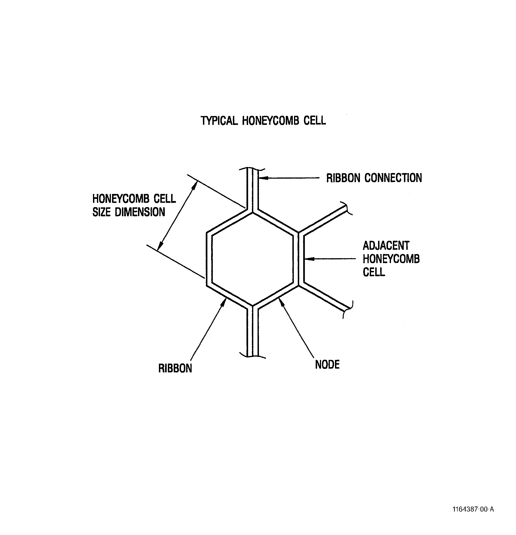
| 3 . | Honeycomb Definitions. |
| Subtask 70-31-04-220-052 |
| A. | The following definitions apply to this standard practice. |
|
| 4 . | Honeycomb Cell Requirements. |
| Subtask 70-31-04-220-053 |
| NOTE: |
|
| A. | Honeycomb Cell Size. |
| NOTE: |
|
| (1) | The average cell size shall be within plus or minus 6 percent (±6%) from nominal cell size as specified per table 1. |
| (2) | No single cell shall vary from the nominal cell size by more than plus or minus 12 percent (±12%) as specified per table 2. |
|
|||||||||||||||||||||||||||||||||||||
| B. | Ribbon Connections. |
| (1) | The following limits shall not be exceeded when ribbons are tack welded at the nodes. |
| (a) | Each 0.25 in. (6.35 mm) of cell height in one node shall contain not more than two tack welds. |
| (b) | Pin holes (holes less than 0.015 in. (0.38 mm) in diameter) through nuggets in more than 10 percent of the nodes. Any hole larger than 0.015 in. (0.38 mm) in diameter through any one nugget is not allowed. |
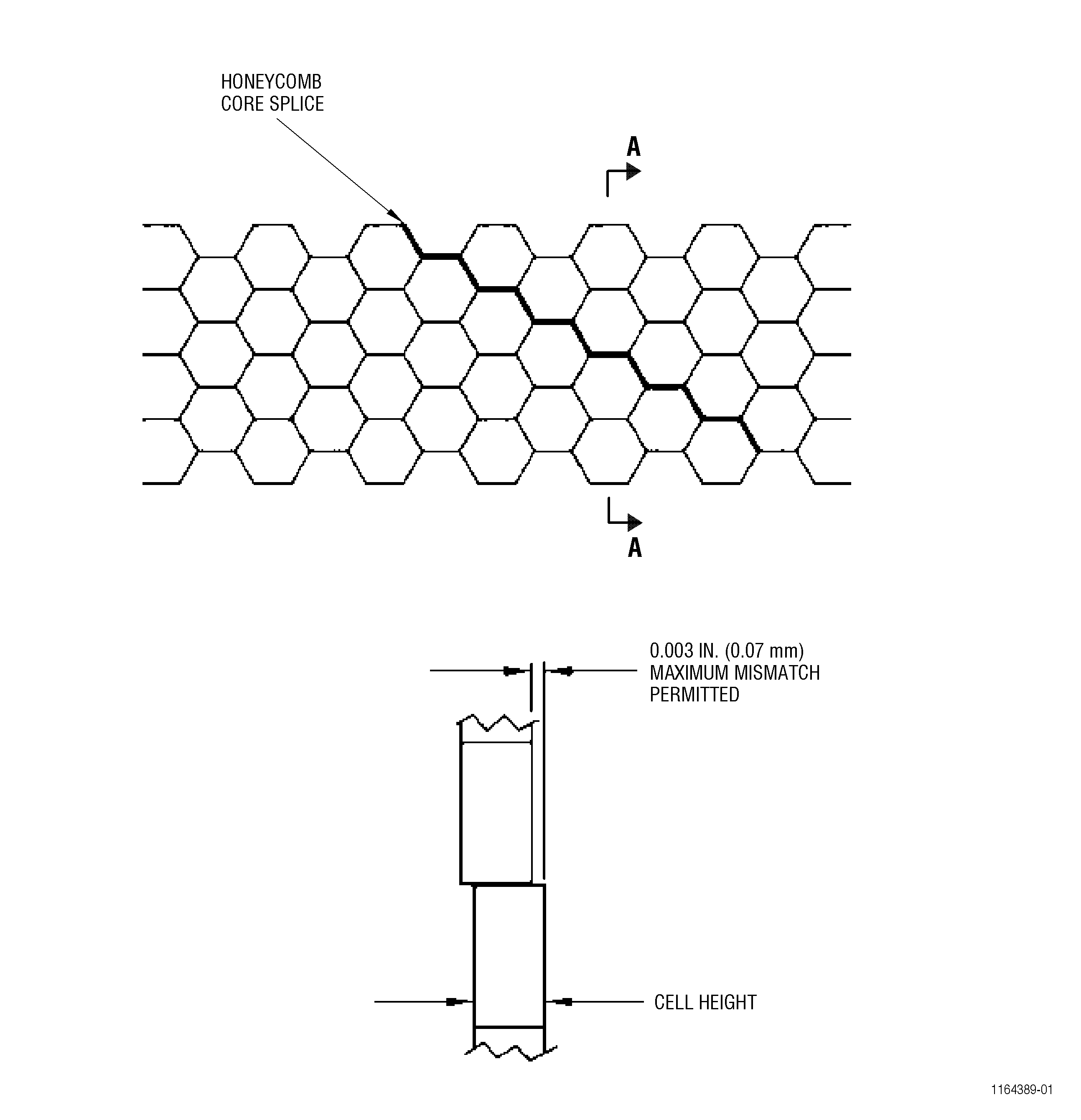
| (c) | Inspect the ribbon ends for mismatch at the core splice. A maximum mismatch of 0.003 in. (0.076 mm) is allowed (see Figure 1). |
| C. | Open Cells for Class A, B, and C. |
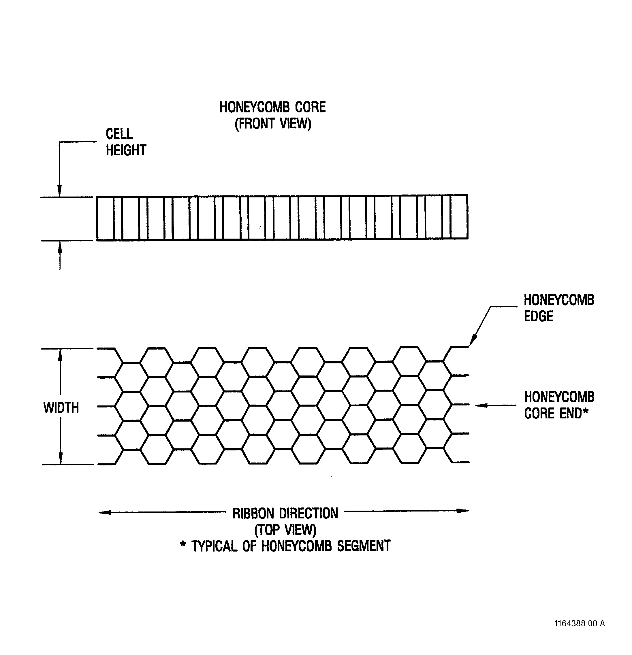
| (1) | Open cells at either edge of the honeycomb core resulting from machining or other processing shall not be allowed. |
| (2) | Open cells at either end of the honeycomb core segment is allowed (see Figure 3). |
| D. | Finished Dimensions. |
| (1) | Finished dimensions of open faced honeycomb shall apply to the total core configuration. Width measurements shall be taken at the extreme edges of the honeycomb core. |
| E. | Honeycomb Core Splices. |
| (1) | Core splices shall conform to the following: |
| (a) | Splices shall be joined on a diagonal. |
| (b) | Splices shall not be closer than 2 inches (51 mm) to another splice (no point in the diagonal line). |
| (c) | Specific splice geometry/configuration shall be defined in the shop manual. |
| F. | Non-Conventional Machining. |
| (1) | Non-conventional machining of the honeycomb core is permitted if the surfaces meet the requirements of Class H in TASK 70-31-05-220-001, Engine Part Surface Integrity Acceptability Limits for Nontraditional Machined Surfaces. |