TASK 70-31-05-220-001
1 . General.
This Standard Practice presents requirements applicable to localized surface areas of repaired parts, as defined by the part-specific repair procedure, that are subjected to nontraditional machining. The use of nontraditional machining can cause significant surface integrity changes to localized areas resulting in alteration of the material or chemical properties of the part.
A.Classification.
This Standard Practice contains the following classes. Unless otherwise specified, the requirements herein apply to all classes:
(1)CLASS A: Static Components - General applications.
(2)CLASS B: Static Components - Other part specific applications where previous experience with increased metallurgical limits on similar parts/materials/features exists (for example: laser drilled holes).
(3)CLASS C: Turbine Airfoil Components - Airfoil trailing edge holes/slots and all other features (tip cap, airfoil cutouts, and spoolie holes).
(4)CLASS D: Turbine Airfoil Components - Non-hole features such as seal slots, and scallops.
(5)CLASS E: Turbine Airfoil Components - Airfoil/band cooling holes.
(6)CLASS F: Rotating parts-disks, spools, shafts.
(7)CLASS G: Rotating parts other than disks spools or shafts.
(8)CLASS H: Open-faced honeycomb seals.
2 . Tools, Equipment, and Materials.
Subtask 70-31-05-220-051
A.As specified in each process reference.
B.Consumable Materials: None.
3 . Referenced Publications.
Subtask 70-31-05-220-052
A.The following documents form a part of this Standard Practice to the extent specified herein. Unless otherwise indicated, the latest issue shall apply.
(1)American Society for Testing and Materials
NOTE:
In case of conflict between ASTM E 140, ASTM E 384, ASTM E 407, or ASTM E 915 and this manual, the requirements of this manual shall apply.
ASTM E 140 - Standard Hardness Conversion Table for Metals.
ASTM E 384 - Standard Test Method for Microhardness of Materials.
ASTM E 407 - Standard Practice for Microetching Metals and Alloys.
ASTM E 915 - Standard Test Method for Verifying the Alignment of X-Ray Diffraction Instrumentation for Residual Stress Measurement.
(2)TASK 70-30-00-200-001, Inspection Methods.
(3)TASK 70-34-00-200-003, Hardness Measurement - General.
4 . Definitions.
Subtask 70-31-05-220-053
A.For purposes of this Standard Practice, the following definitions shall apply:
 
Nomenclature
Definition
Associated Terms
 
Alloy Depletion
A condition at or near the AD surface where the material is deficient in one or more elements of its normal composition. AD is normally associated with intergranular oxidation (IGO).
AD
 
Arc
A continuous flow of electricity between the electrode and the part. If an arc occurs, both the part and the electrode will be damaged.
Spark out
 
Average Recast
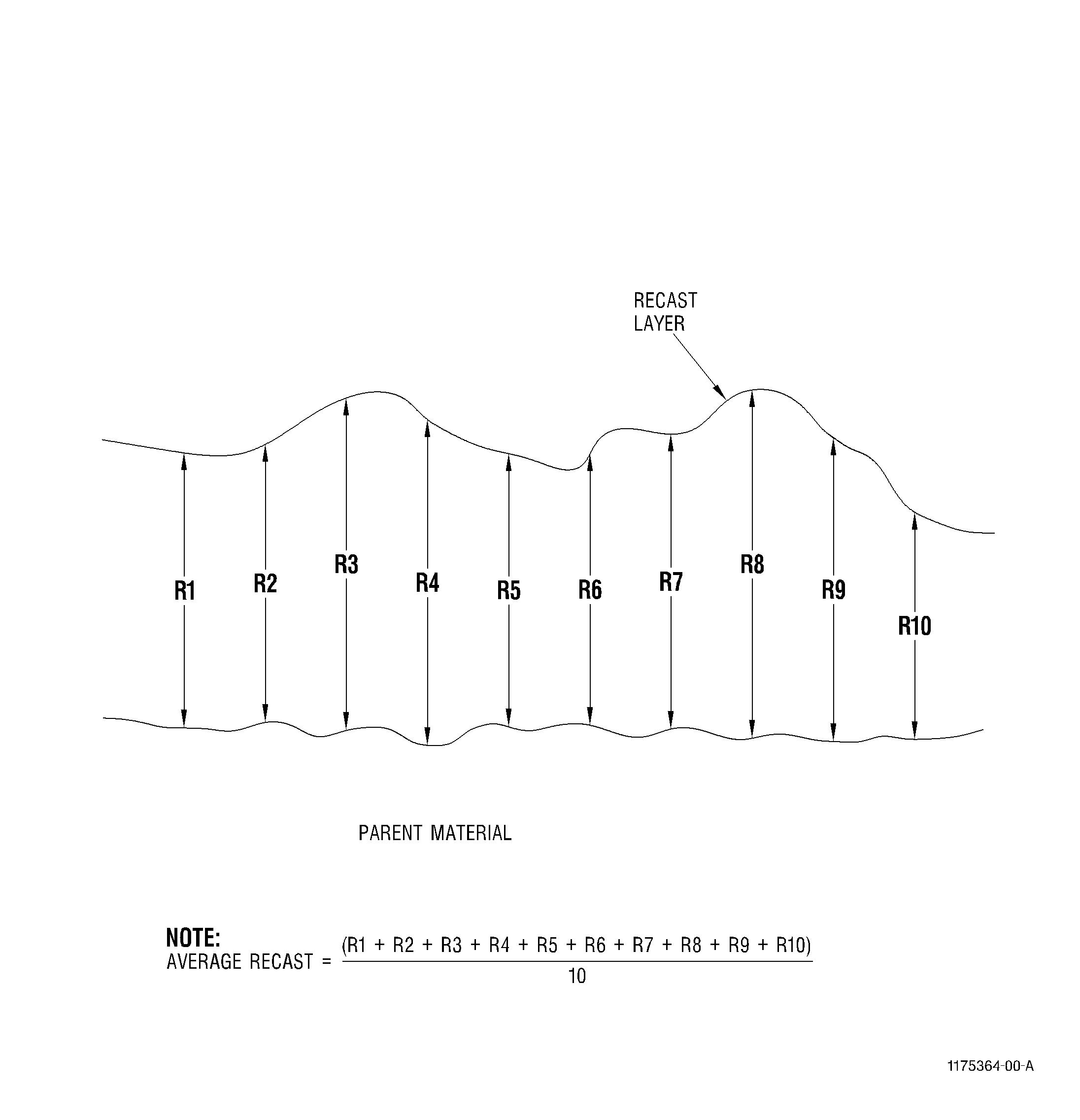
An arithmetic average of 10 individual measurements, which do not include redeposited material or globules, taken at approximately equal distances. An example of Average Recast material measurement is shown in Figure 6.

 
Chemical Milling (CHM)
The controlled dissolution of metal through the action of acid or alkaline solutions, without the application of electric current, to obtain weight reduction and specification design. The amount of metal removed is a function of the composition of the solution, temperature of the solution, and the time immersed in the solution.
CHM
 
Electrical Discharge Machining (EDM)
A material removal process using a series of electric sparks to erode material from a workpiece under carefully controlled conditions.
EDM
 
Electro-chemical Grinding (ECG)
A material removal process using a conductive, non-contacting, rotating wheel that removes conductive material by traversing over the work. This is achieved by the anodic dissolution of a positive workpiece, separated from a shaped, negative electrode(grinding wheel) by a moving conductive electrolyte.
ECG
 
Electro-chemical Machining (ECM)
This process removes conductive material by the anodic dissolution of a positively charged workpiece separated from a shaped, negatively charged electrode by a moving conductive electrolyte.
ECM
 
Hardness Alteration
Changes in hardness of a surface layer as a result of heat, mechanical working, or a chemical change during processing.

 
Intergranular Attack (IGA)
A form of corrosion or oxidation attack in which preferential reactions are concentrated at the surface grain boundaries, usually in the form of sharp notches or discontinuities. Intergranular oxidation (IGO) is a subset of IGA.
IGA
 
Intergranular Oxidation (IGO)
Intergranular oxidation is a form of intergranular attack derived from exposure to elevated temperatures in which there is a depletion in one or more elements of its normal composition of elements, concentrated at the grain boundaries.
IGO
 
Laser Machining
A machining process that uses a series of coherent light pulses to vaporize material from a workpiece.

 
Maximum Recast
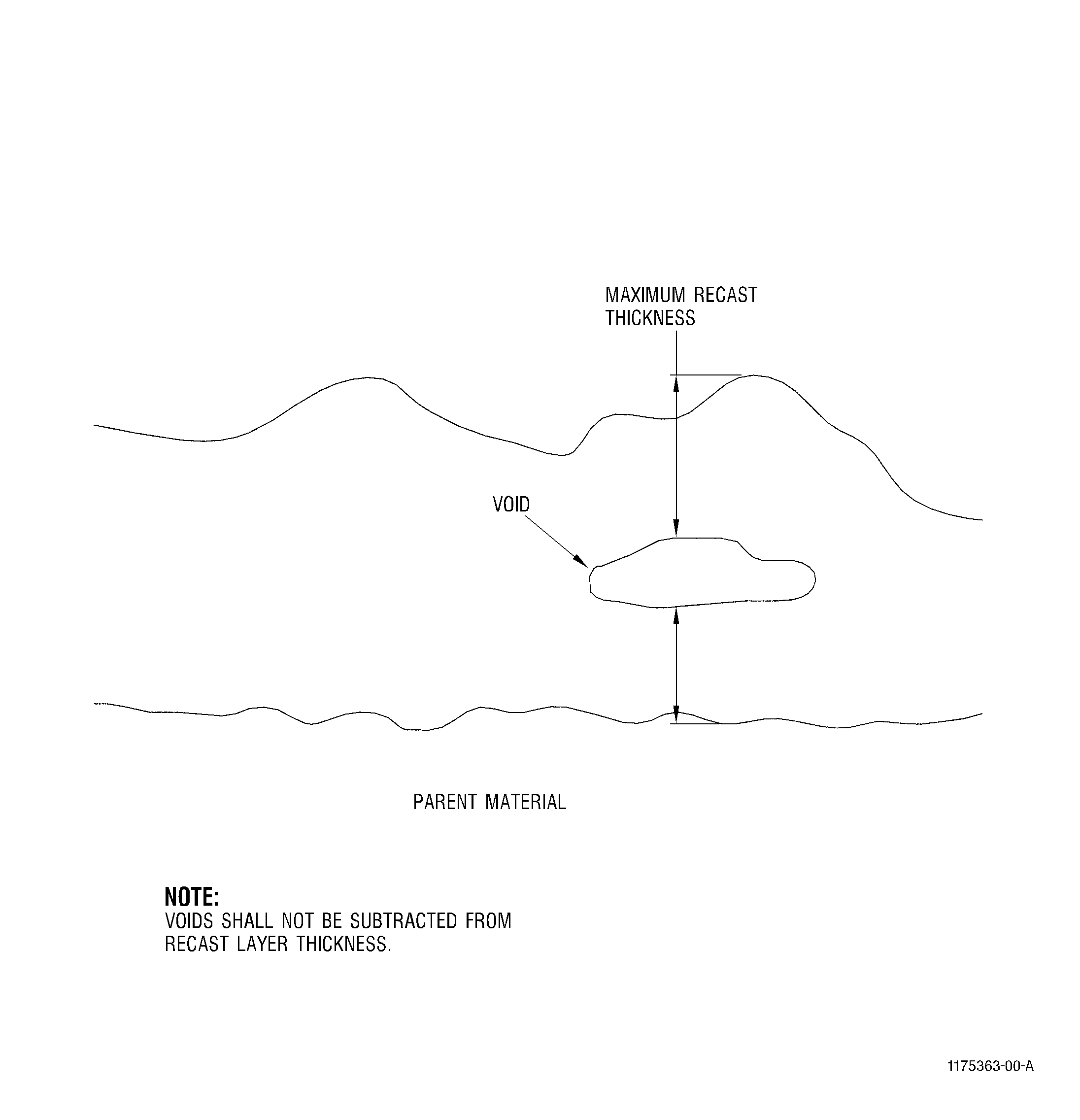
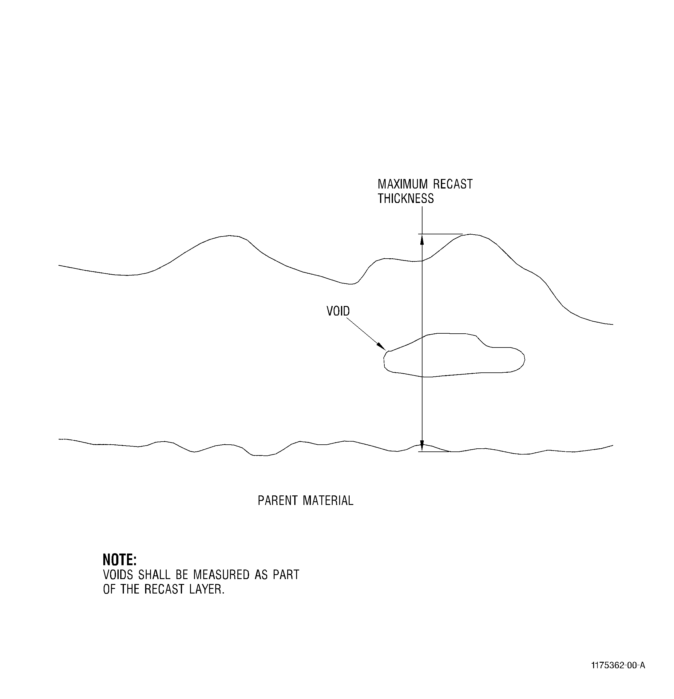
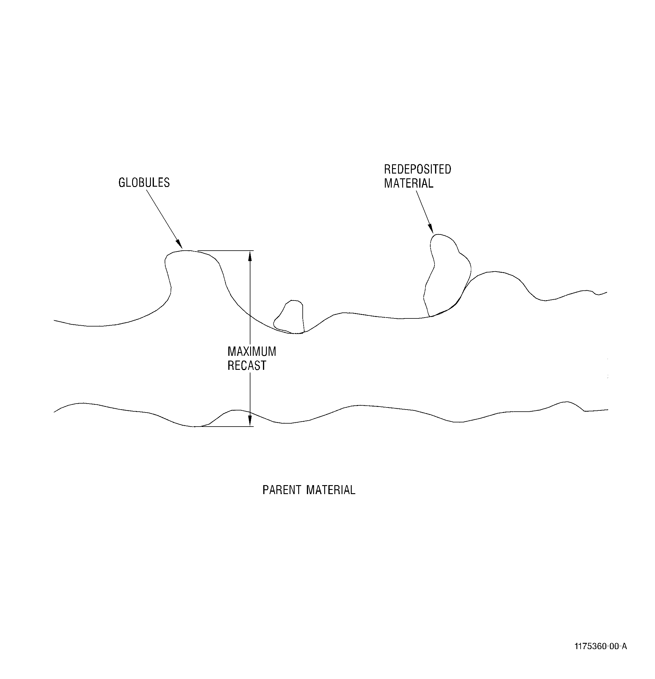
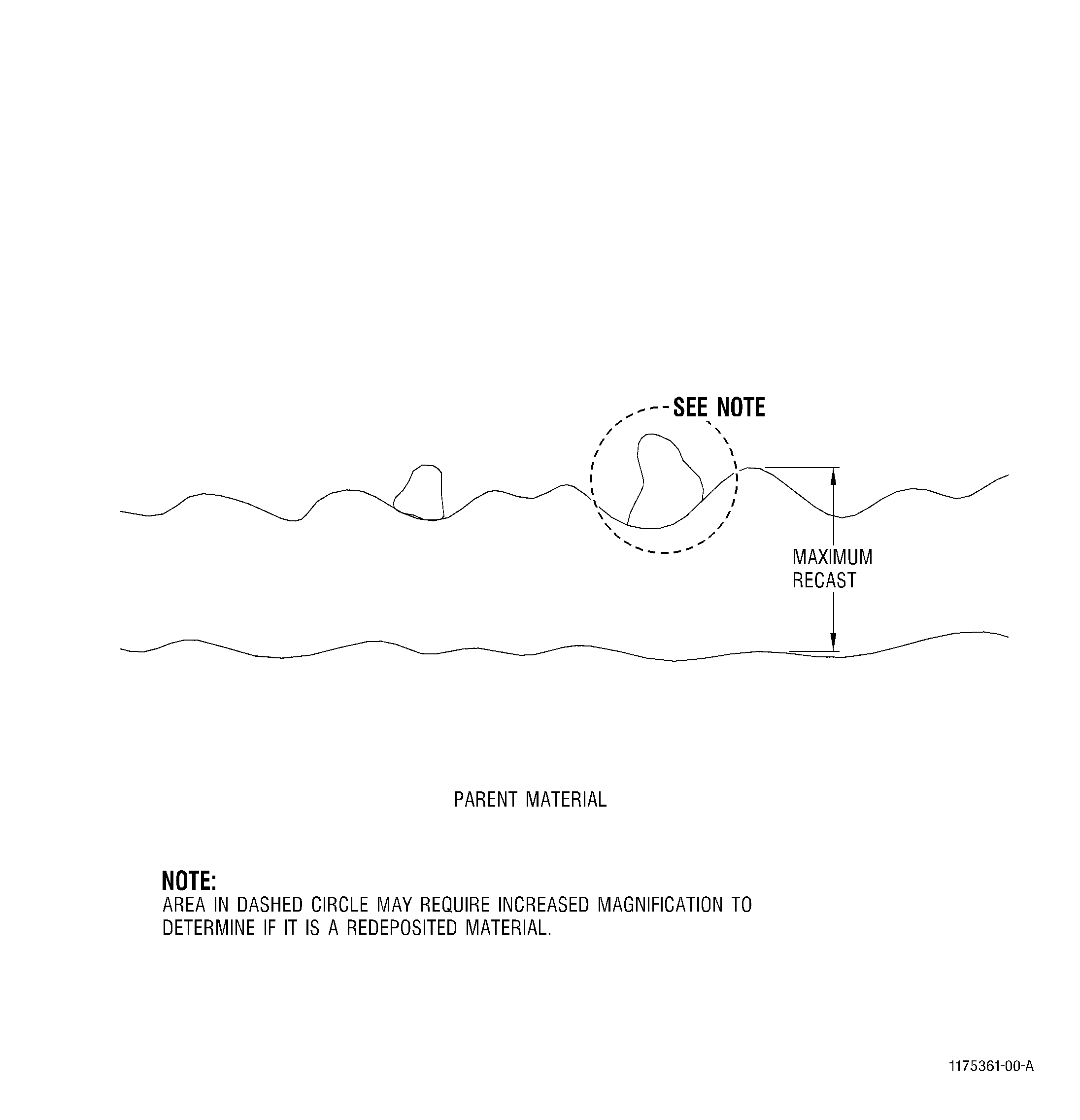
The largest reading of recast material that does not include redeposited material. The largest reading shall include all local swells protruding from normal surface of the recast layer and which exhibit flow lines or structure similar to the continuous recast layer. Examples of Maximum Recast material are shown in Figure 5, Figure 4, and Figure 3.

 
Microcrack
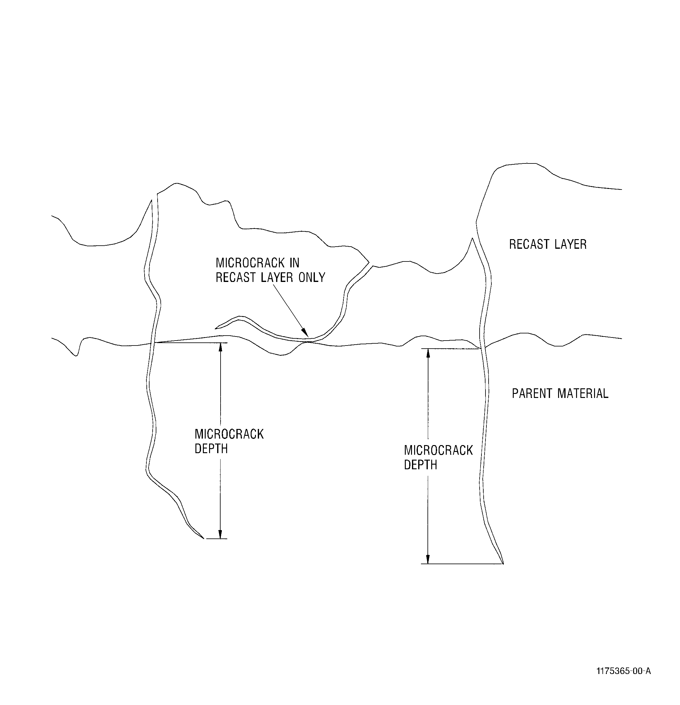
A separation, rupture or fissure altering the continuity of a surface; usually narrow or tight and characterized by sharp edges or abrupt changes in direction. Microcracks can only be detected by metallographic evaluation. Examples of microcracks are shown in Figure 2.

 
Node
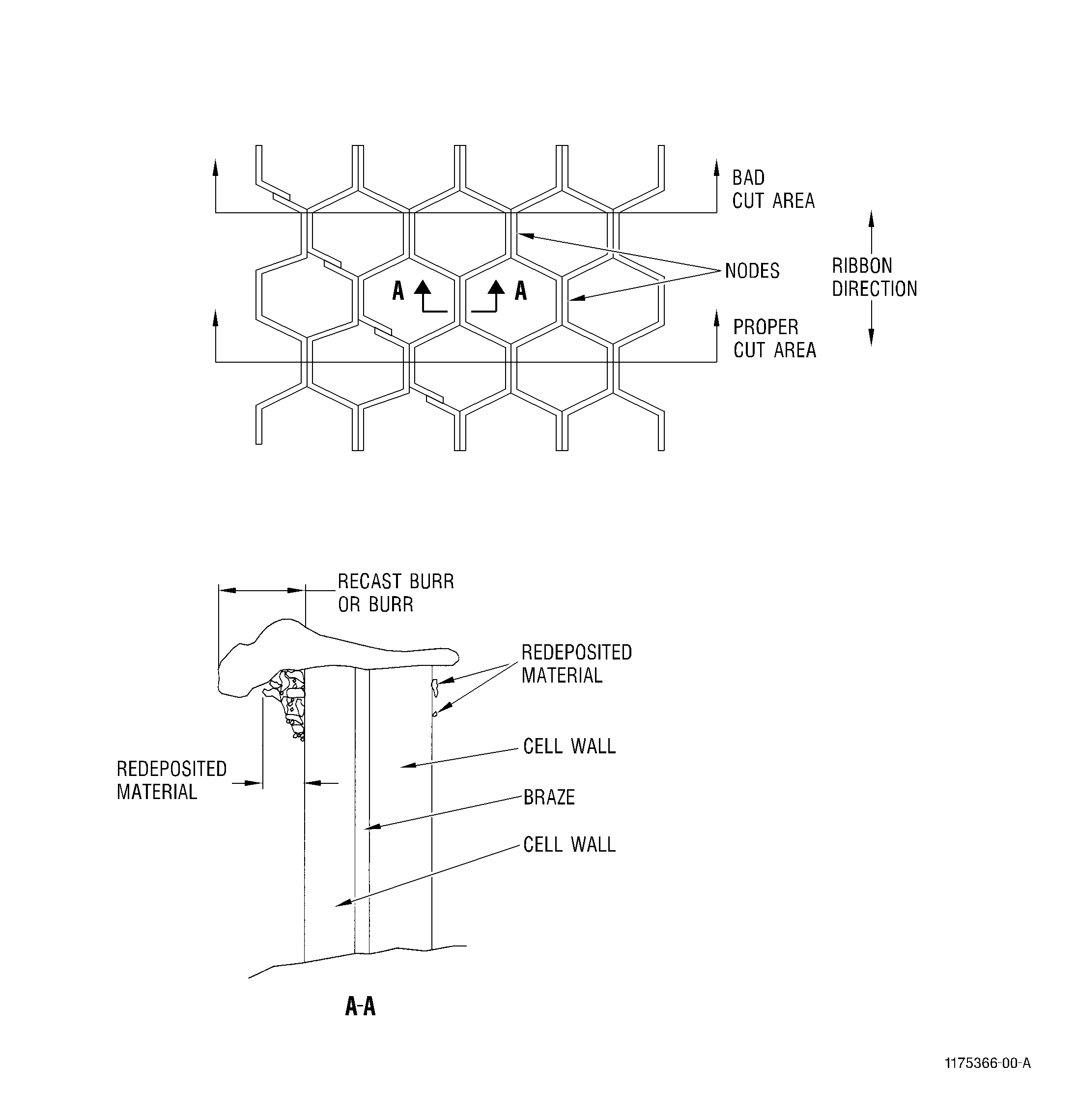
The surface of a formed honeycomb ribbon which contacts an adjacent formed honeycomb ribbon.

 
Nontraditional Machining Processes
Any material removal method where tool-to-workpiece contact is non-existent or minimal and that changes the inherent physical, chemical, or metallurgical properties of the surface. These property changes cannot be fully evaluated by nondestructive methods.
Noncon-ventional Machining
Special Processes
 
Pit
A shallow depression resembling a small crater caused by corrosion or impingement of foreign particles against the surface.

 
Redeposited Material
Material that was removed and rejoined to the surface. Redeposited material normally exhibits the following characteristics:
(1) Not tightly adherent to the continuous recast layer with indications of detachment.
(2) An interface layer may be present between the redeposited material and the continuous recast layer.
Note: Examples of Redeposited Material are shown in Figure 5. Magnification greater than 200x may be needed to determine the difference between maximum recast and redeposited material. Redeposited material may be reported for information purposes but shall not be a criterion for acceptance except for open-faced honeycomb as shown in Figure 1.
Spatter
 
Recast Burr or Burr
Recast material which extends over an open honeycomb cell from smearing when machining honeycomb. Example is shown in Figure 1.

 
Recast Layer
The portion of the surface which during the metal removal process becomes molten and resolidifies in place.
Remelted Material/Continuous Recast Layer
 
Recast/Globules
Globules are local swells in the recast layer protruding from the normal surface of the recast layer whose occurrence does not repeat at regular intervals. Globules are usually defined as having a height-to-width ratio greater than 1, and do not show evidence of detachment or an oxide layer between the globule and a continuous recast layer. Globules exhibit flow lines or structure continuous with the recast layer.
Globular Recast
 
Residual Stresses
Those stresses which remain in a material after all external influences have been removed.

 
Supplier
Source who provides material, parts, or services for incorporation into specified parts.

 
Surface Finish
Surface roughness (Ra) expressed in microinches or micrometers.
Ra
 
Surface Integrity
The surface condition or properties of a material resulting from a controlled manufacturing process.

 
Traditional Processes
Any machining method involving substantial tool/workpiece contact.

 
Thermal Machining
Material removal processes that remove material by the selective application of thermal energy. Examples of Thermal Machining are Electro-Discharge Machining and Laser Machining.

Figure 1   Open-Faced Honeycomb Examination
Figure 2   Microcrack Depth
Figure 3   Incorrect Measurement of Recast Layer with a Void
Figure 4   Correct Measurement of Recast Layer with a Void
Figure 5   (Sheet 1 ) Maximum Recast Example
Figure 5   (Sheet 2 ) Maximum Recast Example
Figure 6   Average Recast Thickness
5 . Requirements.
Subtask 70-31-05-220-054
A.Surface Integrity Identification.
Each surface that requires assured surface integrity shall be identified in the specific repair procedure.
B.Surface Integrity.
The maximum acceptable limits for designated surface integrity areas are in accordance with the table of acceptability limits, and as follows.
NOTE:
The table of acceptability limits is divided into two tables. Table 1 is for classes A thru D and table 2 is for classes E thru H.
(1)Surface Stress Measurements. If the repair procedure requires shot peening of the designated Surface Integrity areas, tables 1 and 2 apply before shot peen, except residual tensile stress measurements shall not be required on surfaces subject to shot peening.
(2)Diffusion Coated Surface Stress Measurement. For diffusion coated surfaces, tables 1 and 2 apply before coating, except residual tensile stress measurements shall not be required on surfaces subject to diffusion coating.
C.Residual Stress Conformance Exceptions.
It is not necessary to verify conformance to the residual tensile stress requirements of tables 1 and 2, if one of the following processing sequences is used:
(1)Shot peening surfaces generated by any traditional or nontraditional method except a thermal method.
(2)Shot peening of a thermal machined surface if a minimum of0.010 inch (0.25 mm) is removed by a non-thermal method before peening.
(3)Low stress grinding after any nontraditional machining method if a minimum of 0.010 inch (0.25 mm) is removed.
(4)Machining of titanium alloys if a minimum of 0.010 inch (0.25 mm) is removed by any chemical or electrochemical method.
(5)Nitriding, carburizing or induction hardening of steel alloys.
D.Surface Finish Conformance Exception.
It is not necessary to verify conformance to the surface finish requirements of tables 1 and 2 if the nontraditional machined feature cannot be measured using a surface profilometer.
(1)Finished dimensions of open-faced honeycomb shall apply to the total core configuration. Width measurements shall be taken at the extreme edges of the honeycomb core.
 
Acceptability Limits - Table 1 - Class A thru Class D
 
Characteristic
Class A
Class B
Class C
Class D
 
Microcracks
Recast layer only
0.0015 inch
(0.038 mm)
parent metal cracking
permitted
Recast layer only
Recast layer only
 
Intergranu-lar
Attack,
Intergranular
Oxidation
0.0015 in.
(0.038 mm) depth max
0.0015 in.
(0.038 mm) depth max
0.0015 in.
(0.038 mm) depth max
0.0015 in.
(0.038 mm) depth max
 
Alloy Depletion,
Carbide Depletion
0.0015 in.
(0.038 mm) depth max
0.0015 in.
(0.038 mm) depth max
0.0015 in.
(0.038 mm) depth max
0.0015 in.
(0.038 mm) depth max
 
Recast Layer
0.002 in.
(0.05 mm) depth max
0.004 in.
(0.10 mm) average depth
0.008 in.
(0.20 mm) depth max
0.001 in.
(0.03 mm) average depth
0.002 in.
(0.06 mm) depth max
0.002 in.
(0.05 mm) average depth
0.004 in.
(0.10 mm) depth max
 
Burrs, Recast
Burrs, Redeposited
Material 1
NA
NA
NA
NA
 
Hardness
Alteration
Rehardening
NA
NA
NA
NA
 
Hardness
Alteration
Softening
NA
NA
NA
NA
 
Residual Tensile Stress
NA
NA
NA
NA
 
Pitting
0.001 in.
(0.03 mm) depth max
0.001 in.
(0.03 mm) depth max
0.001 in.
(0.03 mm) depth max
0.001 in.
(0.03 mm) depth max
 
Surface Finish
250 max
250 max
250 max
250 max
 
NOTE:
1Examples shown in Figure 1. Redeposited material must be contained within the top 25 percent of the finish machined cell height.
 
Acceptability Limits - Table 2 - Class E thru Class H
 
Characteristic
Class E
Class F
Class G
Class H
 
Microcracks
0.002 in. (0.05 mm) parent metal cracking permitted
None Allowed
Recast layer only
Recast layer only
 
Intergranu-lar Attack, Intergranu-ular Oxidation
0.0015 in. (0.038 mm) depth max
0.0005 in. (0.013 mm) depth max
0.0015 (0.038 mm) depth max
 
Alloy Depletion, Carbide Depletion
0.0015 in. (0.038 mm) depth max
0.001 in. (0.03 mm) depth max
0.0015 (0.038 mm) depth max
 
Recast Layer
0.004 in. (0.10 mm) ave. depth 0.008 inch (0.20 mm) depth maximum
None Allowed
0.0005 in. (0.013 mm) depth max
0.002 in. (0.051 mm) ave. depth, 0.004 in. (0.102 mm) depth max
 
Burrs, Recast Burrs, Redeposited Material 1
NA
NA
NA
0.003 in. (0.08 mm) depth max
 
Hardness Alteration Rehardening
NA
0.002 in. (0.05 mm) max. depth. 3HRc max or equivalent2, specified for the part.
NA
 
Hardness Alteration Softening
NA
0.002 in. (0.05 mm) max depth. 3HRc max. or equivalent2, specified for the part.
NA
 
Residual Tensile Stress
NA
20 ksi (138 Mpa) max at more than 0.001 in. (0.03 mm) below surface
NA
 
Pitting
0.001 in. (0.03 mm) depth max
NA
 
Surface Finish
250 max
250 max
250 max
NA
 
NOTE:
1Examples shown in Figure 1. Redeposited material must be contained within the top 25 percent of the finish machined cell height.
 
NOTE:
2Equivalent hardness shall be in accordance with ASTM E 140.
6 . Procedure.
Subtask 70-31-05-220-055
A.Residual Stress Measurement Procedure.
To be determined as specified through repair procedure or selection of method from ASTM E 915 X-Ray Diffraction specification.
B.Surface Finish Measurement Procedure.
(1)Surface Finish is to be measured using a surface profilometer with a mechanical (stylus) contact.
(2)For Class C, D, and E, surface finish is to be measured in a direction parallel to airflow.
C.Metalographic Specimen Preparation.
(1)Methods should be selected which will result in good edge retention since the characteristics being evaluated may measure from 0.0001 to 0.0005 inch (0.003 to 0.013 mm).
(2)This procedure cannot and does not attempt to describe all the variations in technique used successfully by individuals in various laboratories, but is restricted to the preparation of specimens for most recast and IGA evaluations.
(a)Sectioning.
1The specimen should be cut slowly, with an adequate supply of coolant directed onto the cutting area. Direction of the cut and rotation of the wheel should be through the surface to be evaluated, moving toward the parent material. Always cut with the surface to be evaluated in compression. Thus, if using a cutting wheel, the wheel must enter the surface to be evaluated first, then the parent material.
2Open-faced honeycomb must be sectioned perpendicular to the ribbon direction and through the nodes. Example shown in Figure 1.
(b)Mounting Specimens.
1Mounting materials that require extensive pressure for bonding or curing should not be used.
2Epoxy mounting materials work very well, and the use of vacuum degassing techniques during the mounting process is also recommended. A good bond between the mounting medium and the specimen is essential for good edge retention. The use of backup materials, such as Nickel plate, on the surface to be evaluated is also helpful.
(c)Grinding and Polishing
Many techniques exist for preparation via either automatic or manual methods. For reproducibility and consistency, automated grinding/polishing is recommended. Techniques must be chosen with flatness and edge retention as primary goals since the surface alteration layer may be on the order of 0.0003 inch (0.008 mm) or less. Guidelines/procedure for the preparation process should include control of the following parameters:
NOTE:
Monitoring and control of the referenced process characteristics will produce samples suitable for recast evaluation.
1Lubrication Frequency.
2Time.
3Grinding Format.
aDisc.
bPapers.
4Type of Polishing Cloth.
aNap.
bNo nap.
5Pressure (per mount).
6Type of Abrasive.
aSize.
bManufacturing Method.
7Speed.
aHead.
bTable.
8Rotation of Head compared to Table.
aComplimentary.
bCounter.
9Control of Solutions.
apH.
bConcentration.
(d)Marking
Mark all metallographic sections so that they can be cross-referenced to the required part/lot.
(e)Etching.
Etching of micrographic samples when required is to be determined as specified through repair procedure or selection of method from ASTM E 407, Microetching Metals and Alloys.
D.Microcrack Evaluation Procedure.
The presence of cracks should be evaluated at 200 - 500x magnification in the unetched condition. Care should be taken to distinguish between actual cracks and metallographic scratches( Figure 2).
E.Intergranular Attack Evaluation Procedure.
(1)The presence of intergranular attack should be evaluated after etching at a magnification of 400 - 500x. Higher magnification may be used/required to determine depth.
(2)The depth if IGA is determined by the maximum individual occurrence/observation perpendicular to the surrounding surface.
F.Alloy Depletion.
Alloy depletion analysis is done through metallurgical examination after etching at a minimum of 500x magnification. The alloy depletion(AD) shows the difference between intergranular attack (IGA) and intergranular oxidation (IGO). IGA does not have AD.
G.Recast Layer Thickness Measurement.
(1)Recast analysis through metallurgical examination after etching should be done at a minimum of 200x magnification. The micro is to be an actual representative part (scrap part is acceptable), or a coupon of the same alloy in the same heat treated condition.
(2)Average recast thickness measurement is to be the average of 10 thickness readings, equally spaced, perpendicular to the adjacent parent material surface.
(3)Maximum recast is to be reported as the largest individual reading from paragraph 6.G.(2) above( Figure 5 thru Figure 6).
H.Hardness Alteration Measurement.
(1)Refer to TASK 70-34-00-200-003, Hardness Measurement - General. Microhardness should be used as the preferred method due to the minimal thickness of the altered area. Microhardness is to be as specified through repair procedure or selection of method from ASTM E 384, Standard Test Method for Microhardness of Materials.
(2)Report converted hardness measurements as follows: the original measurement is to be reported first with the converted number in parentheses. For example: 353HB (38HRC).
7 . Quality Assurance Provisions.
Subtask 70-31-05-220-056
A.Conformance Processing.
The methods used to verify conformance with paragraph 5.B shall be as approved by the purchaser.
B.Specimen Testing.
Specimens processed at the same time, and under the same conditions as the parts they represent, can be used in lieu of testing processed parts.
C.Recast Layer Determination.
The average and maximum recast layer thickness shall be determined by metallographic examination at a magnification of 200x minimum. Where multiple recast layers exist, the recast layer reading shall be determined by measuring the sum of the recast layers.
D.Nontraditional Machined Finish Qualification.
When the repair procedure permits a part to be finish machined by a nontraditional machining process (for example: EDM) without subsequent metal removal by a traditional process, a specimen representative of the part (same material), shall be processed in accordance with a quality plan.