| COMMERCIAL ENGINE STANDARD PRACTICES MANUAL | Dated: 08/25/2017 | |
| SPM 70-32-10 2 MHz EDDY CURRENT INSPECTION OF BORES IN ROTATING ENGINE HARDWARE USING SYSTEMS UNDER COMPUTER, NUMERIC, OR ROBOTIC CONTROL | ||
| COMMERCIAL ENGINE STANDARD PRACTICES MANUAL | Dated: 08/25/2017 | |
| SPM 70-32-10 2 MHz EDDY CURRENT INSPECTION OF BORES IN ROTATING ENGINE HARDWARE USING SYSTEMS UNDER COMPUTER, NUMERIC, OR ROBOTIC CONTROL | ||
| TASK 70-32-10-250-003 |
| 1 . | General. |
| A. | This document describes the equipment, techniques, and procedures for conducting component level, 2 MHz eddy current inspections of bores in engine run rotating hardware manufactured from titanium, Inconel and Ren. alloys. The inspection areas and specific requirements are detailed in the appropriate inspection scan plans and operators scanning logs included in this document or in applicable Service Bulletins and Engine/Shop Manuals. |
| B. | This inspection procedure utilizes a 2 MHz eddy current technique to inspect various part surface features (i.e., bore inside diameter, bore faces, bore corners, webs, etc.). |
| C. | Inspection systems under computer, numeric, or robotic control shall be used for this inspection, which may be accomplished in air or water. |
| D. | For specific cases where the procedure or equipment described in this document cannot be applied in their total content, specific exceptions shall be obtained in writing from GE Aviation Operations Center (AOC) to document the deviation. Refer to the List of Suppliers in Step 4 of 70-80-00. |
| E. | The following documents shall form a part of this procedure to the extent specified herein. Unless a specific issue is specified, the latest revision shall apply. |
| (1) | Appropriate equipment instruction manuals. |
| (2) | National Aerospace Standard (NAS-410) (latest revision). |
| (3) | Appropriate Service Bulletin or Engine/Shop Manual procedure. |
| F. | The following requirements shall be met by inspection personnel: |
| (1) | Personnel performing this inspection must be certified in accordance with National Aerospace Standard (NAS-410), American Society of Nondestructive Testing (ASNT-TC-1A), Air Transport Association Specification No. 105 (ATA 105), COSAC, or any equivalent certification document acknowledged by the local regulatory agencies. |
| (2) | It is strongly recommended that personnel performing this inspection receive practical training in the use of this procedure and must demonstrate proficiency in the calibration, inspection and evaluation routines before accept/reject authority is delegated. |
| (3) | Any training which may be provided regarding the performance of this inspection does not imply that the personnel who receive that training have met the requirements for inspector certification in accordance with the appropriate certification document. |
| 2 . | Equipment. |
| Subtask 70-32-10-250-031 |
| A. | The instrumentation/tooling listed in this section does not include all of the equipment necessary to perform this inspection, but does include all items for which substitution cannot be made without written approval from GE Aviation Operations Center (AOC). Refer to the List of Suppliers in Step 4 of 70-80-00. |
| B. | System and Instrumentation: |
| NOTE: |
|
| (1) | Eddy Current Inspection System |
| (a) | The inspection system used shall be comprised of an approved eddy current instrument, an approved data acquisition device, and an approved 3 or more axis probe manipulator. |
| (b) | The probe manipulator shall be capable of providing accurate probe movement in the axial/radial direction and circumferentially around the test surface during inspection. |
| (c) | The inspection system shall be under computer or numeric control. |
| (d) | The capability of this system must be demonstrated to GE Aviation Operations Center (AOC), prior to approval for this inspection procedure. Refer to the List of Suppliers in Step 4 of 70-80-00. |
| (e) | The system mechanical accuracies for the appropriate axes shall meet the requirements described in table 1 and shall be checked annually. |
| (f) | Use the system mechanical parameters described in Table 2 for the six axis articulate arm robot for eddy current systems. Measure and record the maximum indicator measurement or runout for each data set described in Table 2. The indicator measurement or runout must be over a 12 inches minimum, move between two taught points zeroing the indicator at each end throughout the work envelope. It is necessary the use of a precision square, parallel bars with a dial indicator mounted on the T-axis face of the robot, or other suitable location. All equipment used must be within calibration dates. Systems that have a turn table must have a Robot User Frame or offline Virtual User Frame set at the center of the table. |
|
||||||||||||||||||||||||||||||||||||||||||||||||||||||||||||||||||||||||||||||||||||||||||||||||||||||||||||||
|
|||||||||||||||||||||||||||||||||||||||||||
| NOTE: |
|
| (g) | A list of approved systems and manufacturers for this equipment is available from: |
| GE Aviation Operations Center (AOC). Refer to the List of Suppliers in Step 4 of 70-80-00. |
| (2) | Eddy Current and Data Recording Instruments/Systems |
| (a) | A list of approved eddy current instruments and recording instruments/systems can be obtained from GE Aviation Operations Center (AOC). Refer to the List of Suppliers in Step 4 of 70-80-00. |
| C. | Tooling: |
| (1) | Eddy current calibration standard P/N MOD-030 Titanium or equivalent Titanium calibration standard approved by GE Aviation Operations Center (AOC). Refer to the List of Suppliers in Step 4 of 70-80-00. |
| (2) | Eddy current probes and approved equivalent probe part numbers (PNs) listed in table below or equivalent approved by GE Aviation Operations Center (AOC). Refer to the List of Suppliers in Step 4 of 70-80-00. |
|
| NOTE: |
|
| NOTE: |
|
| NOTE: |
|
| NOTE: |
|
| D. | Eddy current inspection tooling can be obtained by contacting the following: |
| GE Aviation Operations Center (AOC). Refer to the List of Suppliers in Step 4 of 70-80-00. |
| E. | Materials: |
|
| 3 . | Pre-inspection Part Preparation. |
| Subtask 70-32-10-250-032 |
| A. | Visually inspect the features to be scanned under white light for evidence of adhering dirt, cracks, rubbing, fretting, etc. |
| B. | Clean the features by using the applicable process in the Engine/Shop Manual. Rework any visual surface damage by using the applicable process in the Engine/Shop Manual. |
| C. | Prior to inspection, locate the serial number on the part. Mark this location on the forward side of the part using an approved marker (see TASK 70-16-02-350-017, Temporary Marking). This will be the 12:00 o'clock (start/ref) position. |
| D. | Center the part on the turntable so that the probe stays in contact with the part when rotated. If the cam follower probes are not used, centering within 0.005 inch (0.13 mm) is recommended. |
| 4 . | Equipment Set-Up. |
| Subtask 70-32-10-250-033 |
| A. | Connect the equipment and allow it to warm up in accordance with the manufacturer's specifications. |
| NOTE: |
|
| B. | Prepare Teflon tape C10-040 for probe wear face as follows: |
| (1) | Lay a strip of Teflon tape C10-040 approximately 1.0 inch (25 mm) long on a firm, smooth, clean surface. With a razor blade, cut the Teflon tape to a length that will sufficiently cover the probe face. |
| (2) | Apply the tape tightly across the coil face and around each side. Smooth all edges back from the coil. |
| (3) | Draw the probe back and forth across some fabric with the coil face in contact with the fabric. Heat from the resulting friction will soften the tape adhesive to provide a tight fit. Ensure unwrinkled edges adhere to the probe tip. |
| NOTE: |
|
| C. | Insert the eddy current probe into the probe holder. |
| D. | Connect the fixture to the manipulator and align the fixture parallel to the indexing direction. |
| E. | Connect the probe to the eddy current instrument front panel receptacle. |
| F. | Adjust the instrument control settings as shown in Table 3. |
| G. | Adjust the standard so the eddy current probe will travel transverse/perpendicular to the length of the EDM notch. |
|
||||||||||||||||||||||||||||||||||||||||||||||||||||||||||||||||
| 5 . | Equipment Calibration. |
| Subtask 70-32-10-250-034 |
| A. | Connect the equipment and set initial settings per Subtask 70-32-10-250-033, Equipment Set-Up. |
| B. | Position the probe on the calibration standard. |
| C. | Apply approximately 0.100 inch (2.54 mm) of spring compression on the probe fixture. Null the eddy current instrument with the probe on the calibration standard surface away from the electro-discharge machined (EDM) notch and engraving. |
| NOTE: |
|
|
|||||||||||||||||||||||||||||||||||||||||||
| NOTE: |
|
|
||||||||||||||||||||||||||||||||||||||||||||||||
| NOTE: |
|
| D. | Adjust the angle on the eddyscope so lift-off is vertical. This is accomplished by manually lifting the probe off the standard surface and observing the deflection on the CRT. After setting the lift-off, adjust the filters to the correct settings for the desired inspection speed. Refer to Table 5. |
| E. | Turn on the data recording instrument. |
| F. | Perform a scan of the EDM notch at the correct scan speed at a maximum index increment of 0.005 inch (0.13 mm) to determine the peak response from the EDM notch. |
| NOTE: |
|
| G. | Reposition the probe to the point where the peak notch response was received and perform a continuous scan at this point at the correct scan speed. |
| H. | If an inspection speed of greater than 6 inches per second is being used, proceed as follows: |
| (1) | While scanning, adjust the high pass filter to achieve a signal on the CRT of the eddyscope which has the positive and negative legs of the signal as close as possible in amplitude. The high pass filter must not exceed 40 Hz. |
| I. | While scanning, adjust the gain and angle controls on the eddyscope to achieve the correct calibration amplitude for the material to be inspected (± 100 mV) in Channel 1 (vertical deflection) of the recording instrument with the signal on the CRT in the vertical position. The amplitude in Channel 2 (horizontal deflection) should be at its minimum when the signal on the CRT is at the correct vertical position. Re-null the instrument after any changes in gain or angle. |
| NOTE: |
|
| NOTE: |
|
| J. | After completion of the above routine, perform another scan of the EDM notch at a 0.005 inch (0.13 mm) index rate to ensure the calibration is correct. Record this scan on the data recording instrument. |
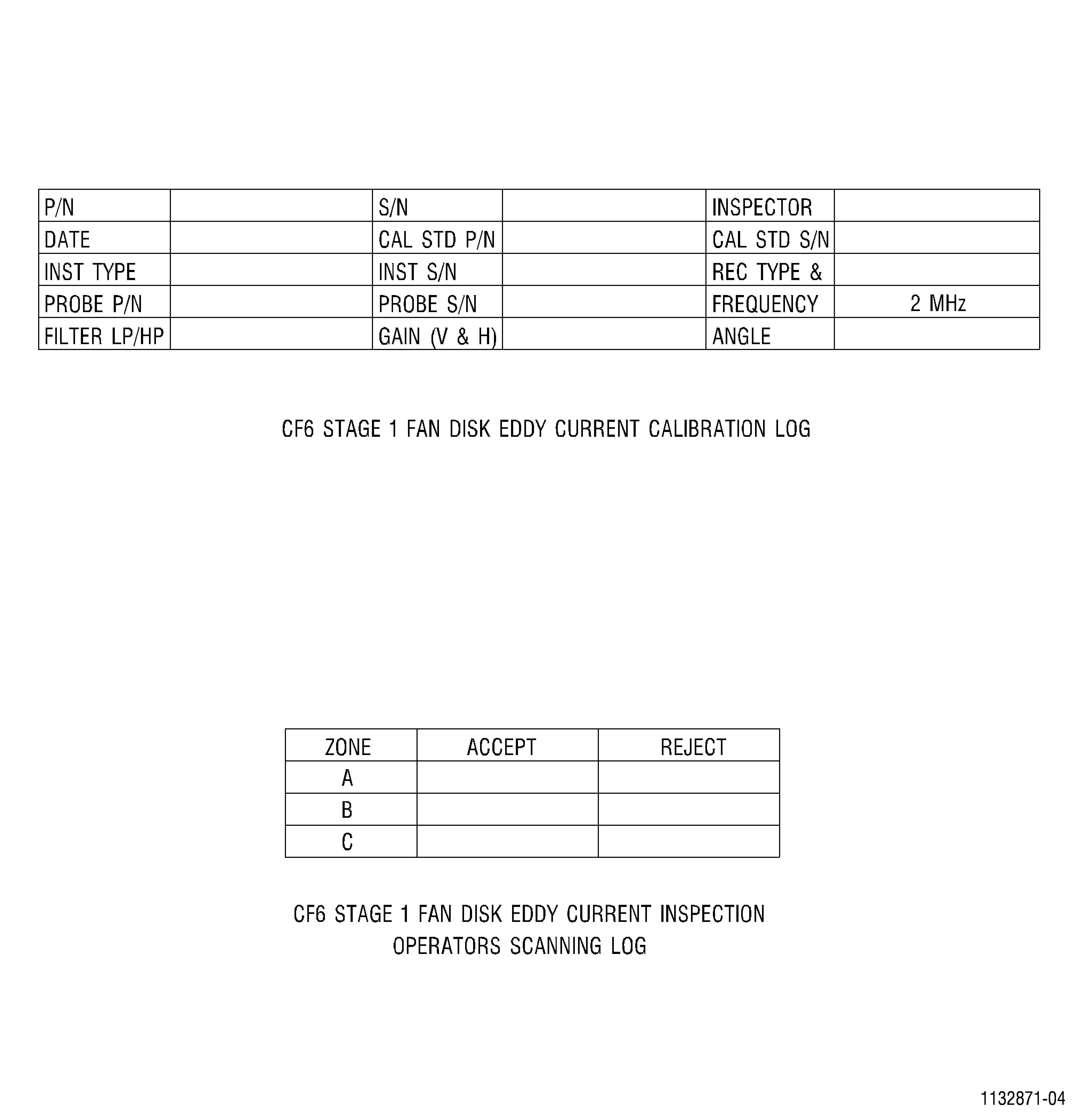
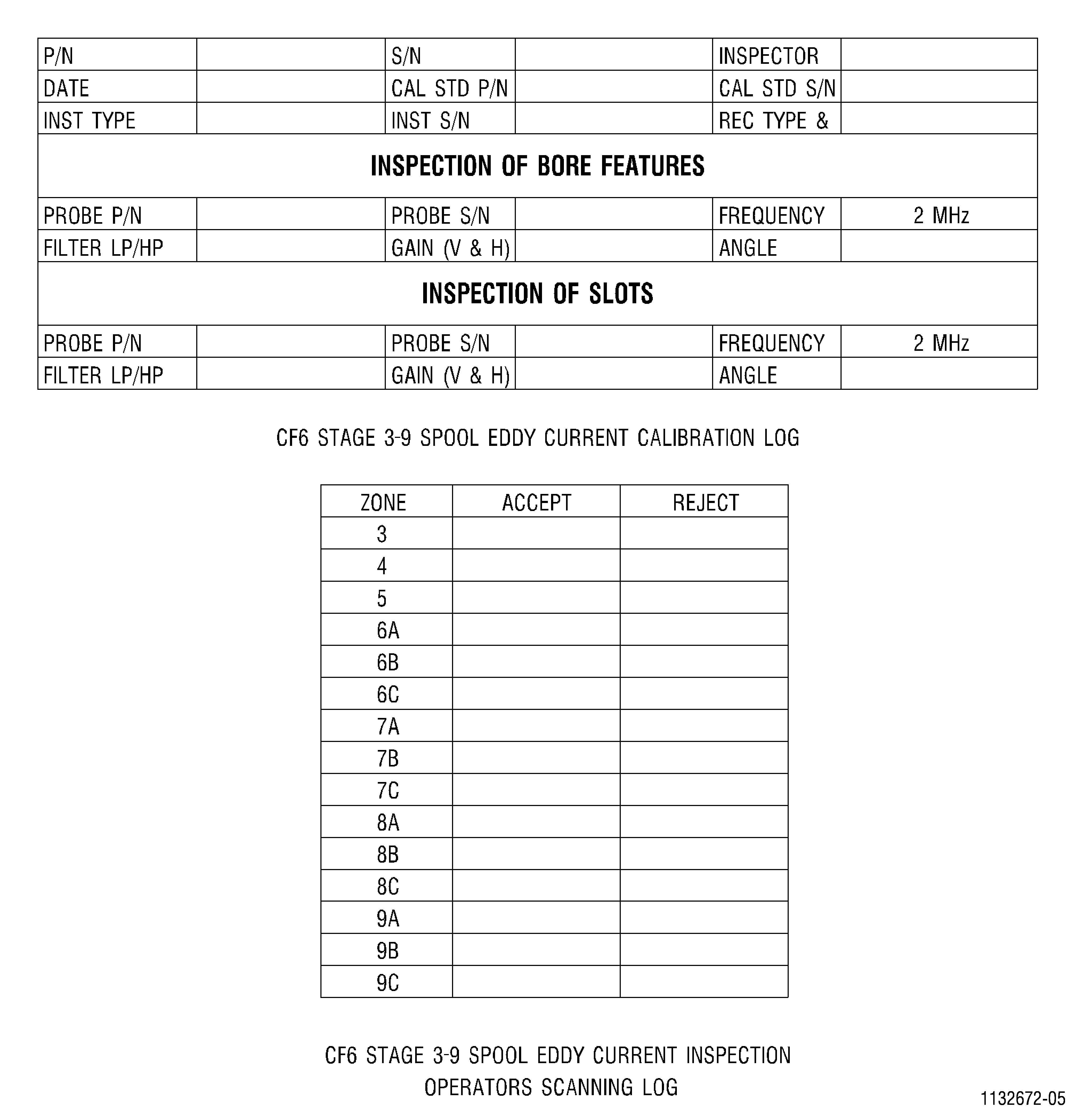
| K. | Record all calibration data onto the appropriate calibration log contained in the scan logs. |
| L. | Use the following guidelines to determine calibration frequency: |
| (1) | Calibrate before and after inspecting a part, whenever an equipment change is made, whenever a power outage occurs, or whenever the operator suspects a problem. |
| (2) | Recalibrate if the amplitude of the response from the EDM notch has decreased by more than 200 mV and reinspect all parts inspected since the previous calibration. |
| (3) | Recalibrate if the amplitude of the response from the EDM notch has increased by more than 200 mV and reinspect any parts which were previously found to be rejected since the previous calibration. |
| 6 . | Part Inspection. |
| Subtask 70-32-10-250-035 |
| A. | Complete pre-inspection part preparation per Subtask 70-32-10-250-032, Pre-inspection Part Preparation. |
| B. | Calibrate per Subtask 70-32-10-250-034, Equipment Calibration. |
| C. | Refer to the appropriate Service Bulletin, Engine/Shop Manual, or the following figures for the appropriate inspection scan plan and inspect all areas of the hardware. |
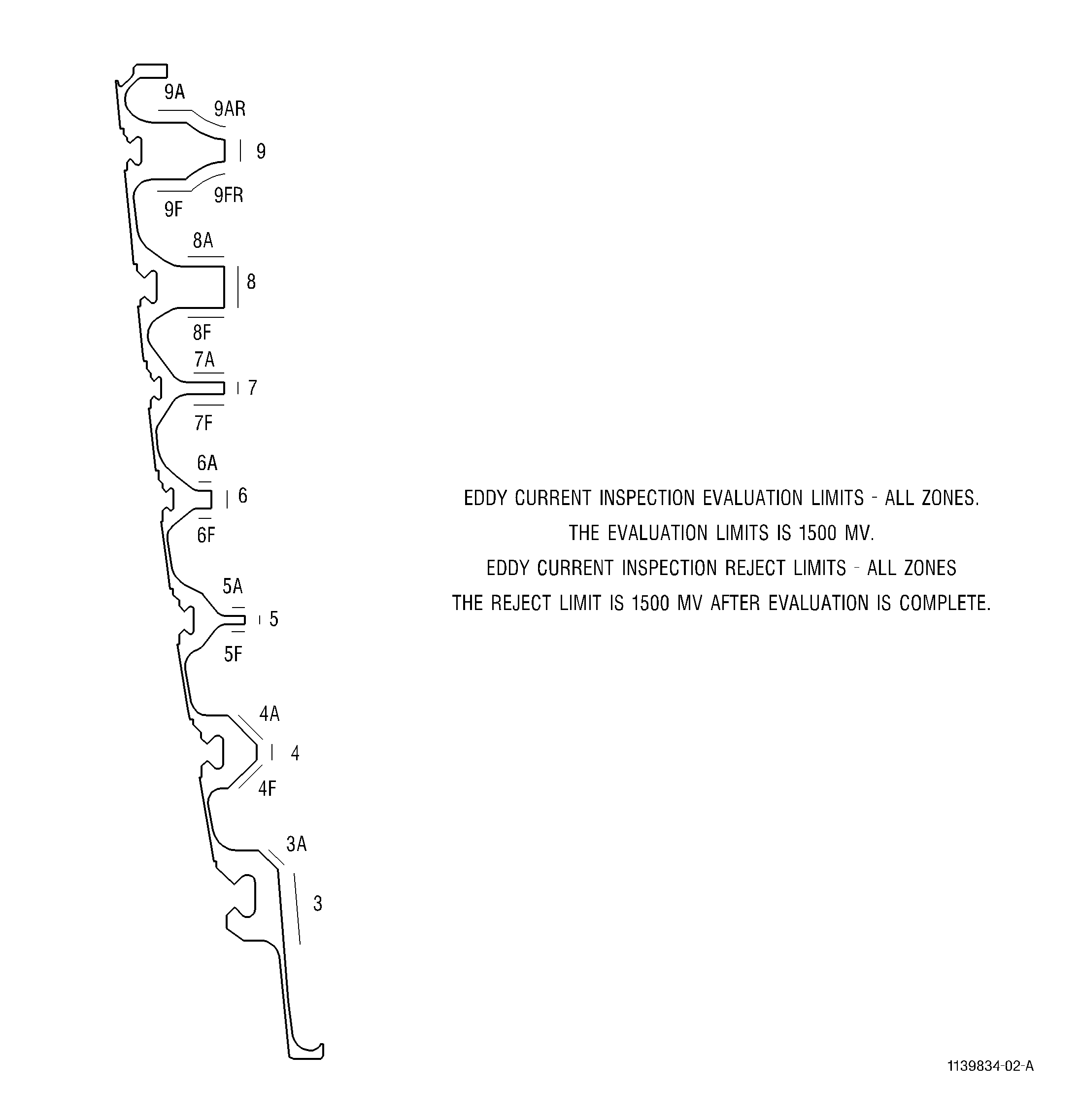
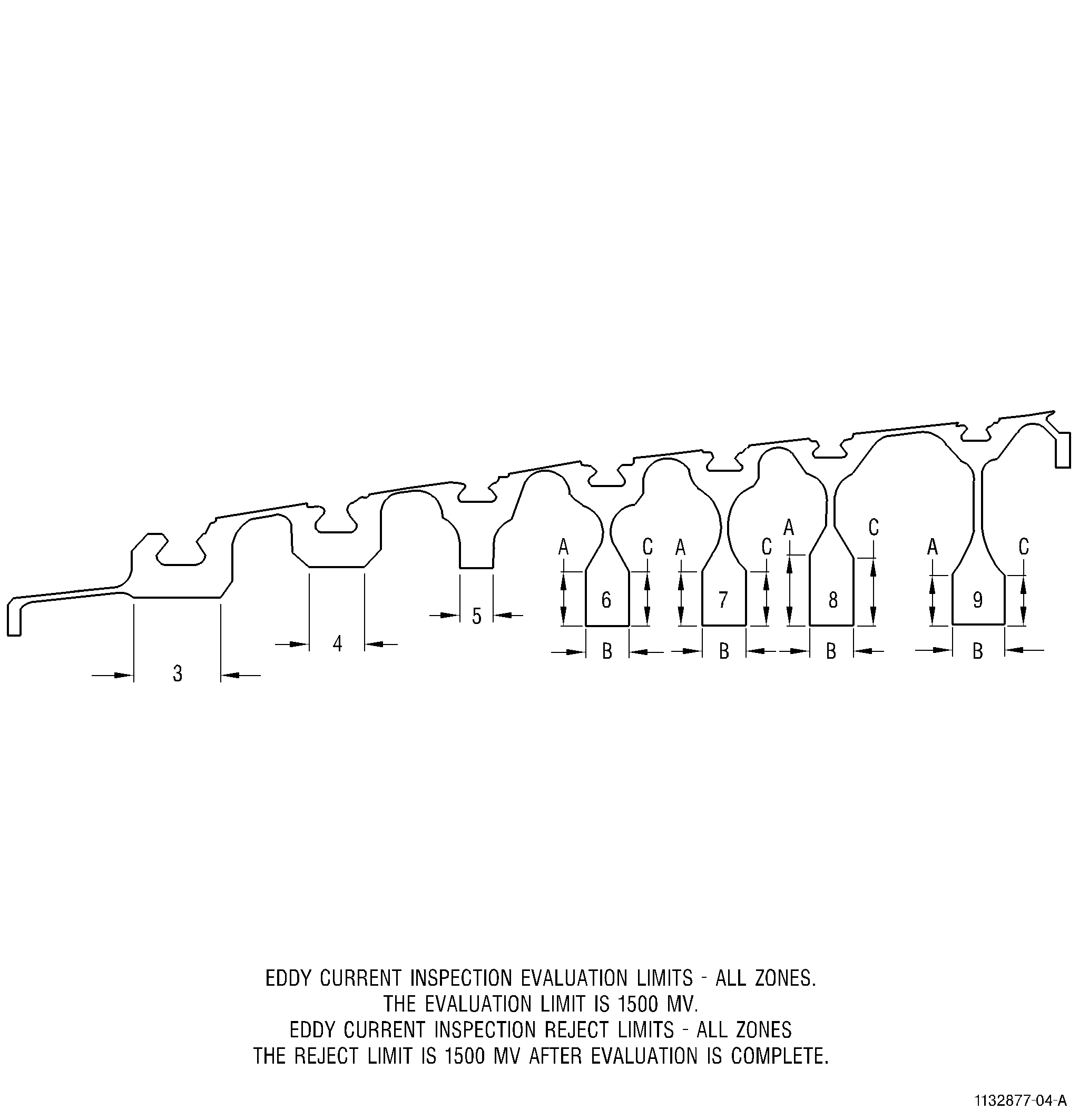
| See Figure 6 and Figure 5 for the CF6 Stage 3-9 Spools. |
| See Figure 4 and Figure 3 for the CF6-6 Stage 3-9 Spools. |
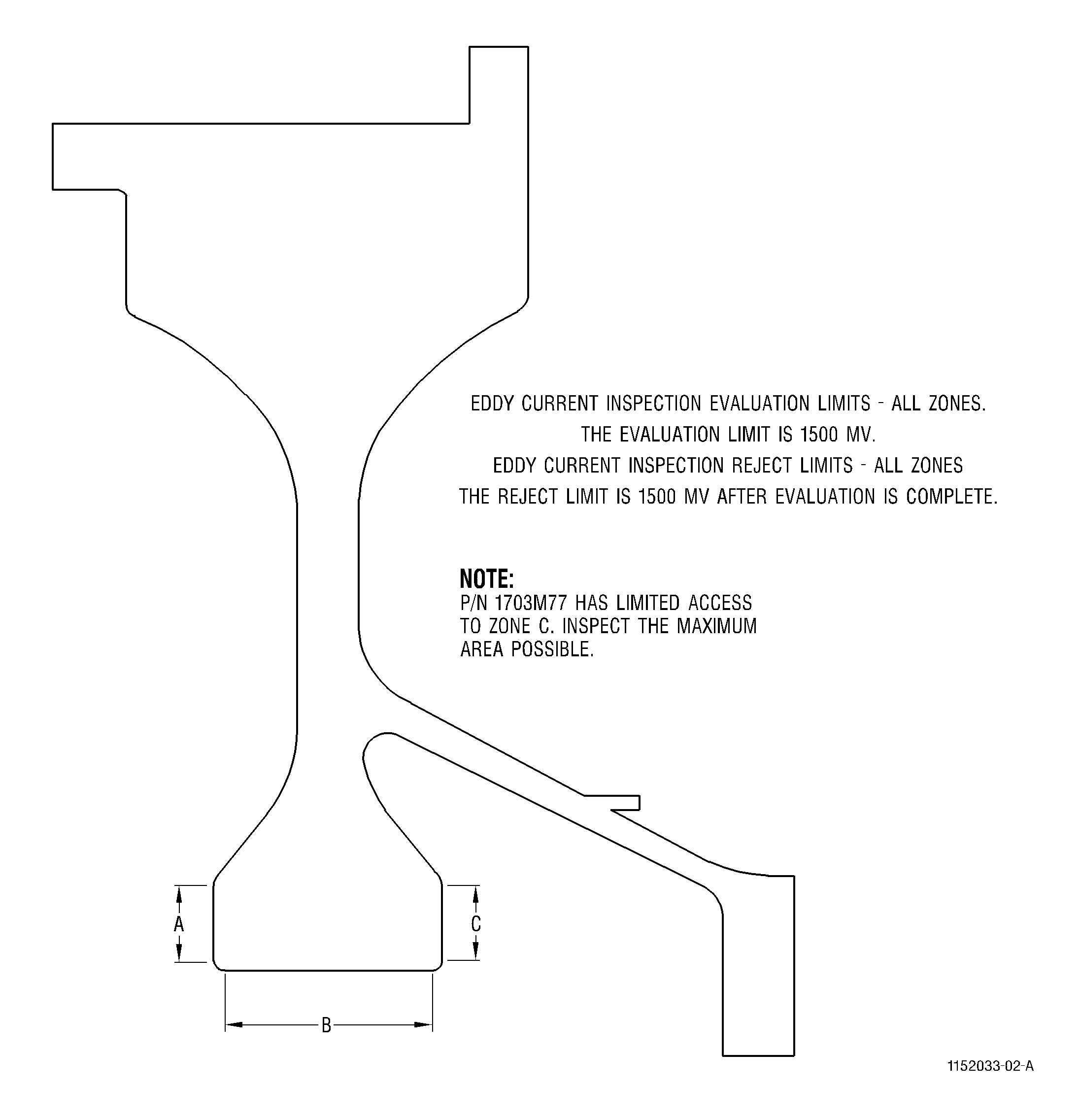
| See Figure 2 and Figure 1 for CF6 Stage 1 Fan Disks. |
| D. | Inspect at a surface scanning speed for all areas of inspection as per Table 4. |
| E. | Index at an increment of 0.025 inch (0.64 mm) per revolution for all areas of inspection. |
| F. | Ensure adequate coverage is provided on all areas by using the cam action of the eddy current probe to completely scan the corner and edge features. |
| G. | Renulling is required for each inspection area. |
| H. | Record all scans on the data recording instrument. |
| I. | Evaluate all repeatable indications with amplitudes greater than or equal to the limit specified in the appropriate Service Bulletin, Engine/Shop Manual, or inspection scan plan. See Subtask 70-32-10-250-036, Indication Evaluation. |
| J. | Record all inspection results on the appropriate Operator's scanning log and the Certificate of Conformance. |
| 7 . | Indication Evaluation. |
| Subtask 70-32-10-250-036 |
| A. | Initially, all indications with amplitudes greater than or equal to the limit specified in the appropriate Service Bulletin, Engine/Shop Manual, or inspection scan plan are considered rejectable. |
| NOTE: |
|
| B. | Clean the area of indication with Scotch Brite C10-010 and approved solvents and reinspect the area. If the indication is reduced to below the reject level, it shall be considered acceptable and noted. If not, continue to evaluate the indication as detailed below. |
| C. | Carefully examine the area of the indication under bright white light using a 5x/10x glass. Note any unusual conditions such as discoloration, handling damage, uneven surfaces, or raised metal, and record these conditions. |
| D. | Reclean and reinspect the area. The following shall apply: |
| (1) | If the indication amplitude falls below the reject level, the area shall be considered acceptable and noted. |
| (2) | If the indication amplitude is reduced but still greater than the reject level, reclean and reevaluate the area since the indication is most likely due to surface contamination. |
| (3) | If the indication amplitude does not fall below reject level, reject the part and identify it for further engineering evaluation and disposition. Record the indication number, area, amplitude, background noise, location, and comments (visual findings) on the Certificate of Conformance. |
| NOTE: |
|
| (4) | If the indication was attributed to visual surface damage and the area was reworked, the reject level is either of the following: |
| (a) | The indication has an amplitude greater than or equal to the limit specified in the appropriate Service Bulletin, Engine/Shop Manual, or inspection scan plan. |
| (b) | The indication exceeds a 3:1 peak amplitude to average background noise. |
| 8 . | Records. |
| Subtask 70-32-10-250-037 |
| A. | As a minimum, document and maintain the calibration logs and operator scan logs with the inspection data package. |
| B. | Record the following for each scan within the scan file. |
| (1) | Area |
| (2) | Date |
| (3) | Start/Stop Location and Feature |
| C. | Document all inspection results. Copies of strip chart recordings of rescans of all indications exceeding the allowable criteria shall be kept with the suspect hardware. The allowable criteria is specified in Subtask 70-32-10-250-036, Indication Evaluation. |
| D. | It is the Inspection Facility's responsibility to maintain all inspection records. The inspection records shall be kept with the permanent record of the part and shall be maintained for the life of the part. The responsibility to maintain the permanent record for the life of the part lies with the owner/operator of the part. |