| COMMERCIAL ENGINE STANDARD PRACTICES MANUAL | Dated: 04/01/2006 | |
| SPM 70-33-01 ANTIFRICTION BEARING INSPECTION | ||
| COMMERCIAL ENGINE STANDARD PRACTICES MANUAL | Dated: 04/01/2006 | |
| SPM 70-33-01 ANTIFRICTION BEARING INSPECTION | ||
| TASK 70-33-01-220-004 |
| 1 . | General. |
| Personnel working with antifriction bearings should be thoroughly experienced and familiar with the special requirements of handling them, as described in TASK 70-14-00-620-003, Handling of Bearings, and of proper cleaning methods( TASK 70-22-01-110-013, Special Cleaning Procedure No. 1 - Cleaning of Bearings). Serviceable limits are provided in the specific engine or shop manual in 72-09-01. The terminology used in this section is in agreement with that of the Antifriction Bearing Manufacturer's Association (AFBMA). |
| The term "functional surface" refers to the entire outer surface of the rolling elements, and the surfaces on the raceways that contact the rolling elements. The corner radius of a roller is a non-functional surface. All other surfaces of the bearing are non-functional surfaces. |
| 2 . | Types of Inspection. |
| Subtask 70-33-01-220-041 |
| A. | The proper inspection of bearings to determine serviceability requires several different types of checks; visual, touch or "feel", dimensional and hardness. Dimensional and hardness checks, being performed with instruments, do not require interpretation; the other types of checks are conclusive only to the extent that the inspector's experience is a reliable guide. The procedures that follow describe indications to be found in bearings undergoing inspection, and include possible causes of damage. |
| 3 . | Procedure. |
| Subtask 70-33-01-220-042 |
| • |
|
| A. | Visual Inspection. |
| Visually inspect each bearing and its parts for the defects listed below. Visual inspection should be accomplished without the aid of magnification. For interpretation of type of condition only, a glass of 10X magnification may be used. |
| Standard scribers used to evaluate surface discontinuities may be fabricated locally, using AISI-01 or AISI-W1 Grade 4, steel. Tolerance of the polished nose radii should be±0.001 inch (±0.03 mm) and scribers should have a Rockwell-C hardness of 55-60. A surface-finish scriber kit especially designed for bearing inspection can be procured from the following: |
| RAE Bearing Service or Carbide Probes, Inc. Refer to the List of Suppliers in Step 4 of 70-80-00. |
| When inspecting bearing surfaces, any defect that cannot be felt with a scriber of designated nose radius is acceptable. No pressure should be exerted on the scriber when checking for defects; the fingers should be used only to guide the scriber. Defects that can be felt on the scriber should be checked for size to the limits stated under the specific defect, using a pocket-sized optical comparator such as the Arco 10-x deLux (F.E. Kiener Co., 1431 Atlantic Boulevard, Los Angeles, California, 90022) or equivalent. Terms and definitions of defects not described in this section can be found in TASK 70-30-00-200-001, Inspection Methods. |
| (1) | Discolored (blue or burned bearings). |
| Refer to Heat Discoloration [ paragraph 3.A.(8)]. |
| (2) | Brinelling (True). |
| (a) | Appearance. |
| Shallow impressions of balls or rollers on race-ways, accompanied by a slight flattening of the balls or rollers, usually at 2 diametrically opposite places on each ball or roller. |
| (b) | Probable cause. |
| Overloading or shock-loading a bearing, usually while stationary, to the degree that rollers, balls, and raceways are permanently deformed by each other. True brinelling often occurs while transporting an assembled engine in a dolly with flat wheels, or over bumpy surfaces, or from using hammers as removal tools. |
| (3) | Brinelling (False). |
| (a) | Appearance. |
| Lines on the raceway at each roller position, or dots on the raceway at each ball position. Minor fretting or light traces of rust may be visible under magnification. |
| (b) | Probable cause. |
| False brinelling occurs while the bearing is stationary, and is often a result of repeated or continuous low amplitude axial vibration. |
| (4) | Burnishing. |
| (a) | Appearance. |
| Smooth metal surface without displacement or loss of material. Surface discoloration is sometimes present along outer edges of the burnished surface. |
| (b) | Probable cause. |
| Light rubbing between nonfunctional surfaces, often under conditions in insufficient or marginal lubrication. |
| (5) | Corrosion or rust. |
| (a) | Appearance. |
| Broken, pitted or discolored surface area which exhibits an orange peel appearance. Areas of corrosion or rust are large groups or relatively shallow small pits. |
| (b) | Probable cause. |
| Exposure of bearing to corrosive atmosphere or materials, inadequate control of temperature and humidity during processing, chemical or electrolytic attack sometimes caused by faulty protection or by breakdown of lubricant. |
| (6) | Fretting corrosion. |
| (a) | Appearance. |
| Characterized by rusty surfaces ranging from black to a fairly bright color, and from well bonded to loosely bonded (sometimes with free particles) respectively. Fretting corrosion occurs most frequently between inner race and shaft, outer race and housing, and race ends and retaining members. |
| (b) | Probable cause. |
| Rapid oxidation of the surfaces of closely fitted parts, usually resulting from small relative movement between 2 mating surfaces, or the alternate expansion and contraction of a portion of a shaft or bearing ring relative to its mating surface. |
| (7) | Galling. |
| (a) | Appearance. |
| Similar to fretting corrosion, but more severe. Distinguished by a significant transfer of material between mating surfaces resulting from friction-welding and subsequent tearing of metal particles. |
| (b) | Probable cause. |
| Excessive motion between 2 poorly lubricated surfaces under heavy load. |
| (8) | Heat Discoloration. |
| (a) | Appearance. |
| Light straw color to deep purple, sometimes iridescent, depending upon temperature. Some heat discoloration of bearings in hot sections of engine is normal. |
| (b) | Probable cause. |
| Lubrication inadequate for proper cooling, bearing directly exposed to hot gases, or over-lubrication causing friction by reducing freedom of motion. |
| CAUTION: |
|
| (9) | Load Path Markings. |
| (a) | Appearance. |
| 1 | Ball bearings: |
| Normally, the unloaded side of the split inner race will show no load path marking. The loaded side will show a load path marking somewhat to one side, but not close to the edge of the shoulder. Oscillating load path markings on the inner race indicate cocked bearings or misaligned shafts. In outer races, the normal load path marking is slightly off center toward the applied load. Both inner and outer race load path markings should be the same distance from the shoulder around the entire bearing. |
| 2 | Roller bearings: |
| The normal load path marking is uniform all around the bearing; i.e., not concentrated on one side of the path. The marking should be about the same distance from the edge of the raceway all around the bearing. |
| (b) | Probable cause. |
| Work-hardening (increased density of crystalline structure) of the raceway caused by the continuous pressure of balls or rollers under load. |
| (10) | Nicks and Dents. |
| (a) | Appearance. |
| Nicks are sharp, well defined incisions; dents are smooth depressions. On functional surfaces, each dent may exhibit the polished appearance of work-hardening around the edge of the depression. Ridges of displaced metal are frequently found at the edges of nicks and dents. |
| (b) | Probable cause. |
| Improper handling, failure to keep elements separated during processing, dirt, chips or other foreign material in bearing that have been run over by balls or rollers during operation. |
| (11) | Pitting. |
| (a) | Appearance. |
| Minute cavities having no sharp, high-stress corners. |
| (b) | Probable cause. |
| Chemical or electrolytic attack, oxidation of bearing surfaces, mechanical action such as chipping, or removal of embedded material. |
| (12) | Roller End-Wear. |
| (a) | Appearance. |
| Concentric or eccentric scratches or rubs (burnishing) on the end of rollers. |
| (b) | Probable cause. |
| Misalignment of one race with respect to the other, or imbalance of the roller element, or axial loading. |
| (13) | Scoring. |
| (a) | Appearance. |
| Deep scrape marks or scratches, often multiple, that can exist on any surface of ball and roller bearings. |
| (b) | Probable cause. |
| Skidding of rollers and balls in the presence of dirt or abrasive foreign particles. Nonfunctional surfaces may be scored by press-fitting bearings into housings or onto shafts containing burrs or foreign matter, or by other faulty mounting procedures. |
| (14) | Scratches and Chafes. |
| (a) | Appearance. |
| 1 | Scratches. |
| Long, narrow, sharp-cornered incisions in any bearing surface. |
| 2 | Chafes. |
| A parallel group of superficial scratches. |
| (b) | Probable cause. |
| 1 | Scratches. |
| Movement of a sharp object across a surface under sufficient pressure to displace metal. |
| 2 | Chafes. |
| Sliding or skidding in the presence of dirt or other abrasive foreign matter, or inadequate lubrication on functional surfaces. |
| (15) | Skidding. |
| (a) | Appearance. |
| A burnished or frosted ring around raceways and sometimes on rollers or balls. Indications of electrical arc discharges may be present as dots, especially if the bearing shows residual magnetism. |
| (b) | Probable cause. |
| Too much or too little lubrication, lubricant too stiff to permit free turning (lubricant may be over-age or of incorrect type), or insufficient loading of bearing. |
| (16) | Spalling, Flaking or Fatigue Spots. |
| (a) | Appearance. |
| Irregular, sharp-edged, rough-bottomed cavities in functional surfaces of bearing. |
| (b) | Probable cause. |
| Internal binding, out-of-round housings or shafts causing ring members to assume mounting over-loads, normal metal fatigue resulting from excessive preloading or use beyond normal life of bearing. |
| (17) | Stains. |
| (a) | Appearance. |
| Discoloration other than burning or heat discoloration and other than varnishing film. Stains are not accompanied by etching or pitting. |
| (b) | Probable cause. |
| Deposits of penetrating dyes in the crystalline structure of the metal. |
| (18) | Varnish Film. |
| (a) | Appearance. |
| Light brown-to-black surface discoloration on bearing surfaces. |
| (b) | Probable cause. |
| Breakdown or carbonization of lubricant resulting from moderate-to-high temperature operation. |
| (19) | Cage Defects - Damage and Wear. |
| (a) | Appearance. |
| Damage and wear may be indicated on cages by one or more of the following conditions: |
| 1 | Broken or cracked edges. |
| 2 | Bent or out-of-round edges. |
| 3 | Nicks or dents in the bronze or steel on land-riding or pocket surfaces, over 0.125 inch (3.18 mm) longest dimension. |
| 4 | Nicks or dents other than those described in fault3, and over 0.250 inch (6.35 mm) largest dimension. |
| 5 | Wear through silver to bronze or steel in the cage pockets, more than 0.125 inch (3.18 mm) wide. |
| 6 | Wear on the land-riding surface through silver into the bronze or steel. |
| 7 | Wear of cage pocket sufficient to let balls or rollers come out of a nonseparable cage. |
| (b) | Probable cause. |
| Faults 1 and 2 are often caused by improper handling, or failure to segregate parts while cleaning. Other defects may be caused by misalignment of inner and outer races, improper lubrication or set-up lubricant. |
| (20) | Cage Defects - Flaking, Peeling and Blistering. |
| (a) | Appearance. |
| Tearing away or separation of plating from the substrate metal. Plating separated but not missing is blistered; plating missing in strips is peeled; other missing patches are flaked. |
| (b) | Probable cause. |
| Bond between substrate metal and plating is imperfect or lacking. |
| B. | Dimensional Inspection. |
| Inspect bearings dimensionally in accordance with the following instructions. |
| (1) | Bearing dimensional inspection conditions. |
| (a) | Temperature. The inspection room temperature must be controlled to be within a range of 66 to 70°F (19 to 21°C) with a rate of change not more than 0.5°F per hour (0.3°C per hour). |
| (b) | Normalization Time. Each bearing must be allowed to equalize to the inspection room temperature for a period of 12 hours before dimensional inspection is attempted. |
| (c) | Bearing Handling: Care should be taken when handling bearings for measurement. Body heat transferred to the bearing can significantly change the dimensions of bearing components, especially thin races or rings. |
| (2) | Bore and outside measurements. |
| (a) | Determine bore diameter with 2-point measuring equipment, taking 4 readings approximately 45 degrees apart. The average of the smallest and largest readings must be within the limits specified in the Engine/Shop Manual. |
| (b) | Determine OD with 2-point measuring equipment, taking4 readings approximately 45 degrees apart. Bearing must be in horizontal position when measuring. The average of the smallest and largest readings must be within the limits specified in the Engine/Shop Manual. |
| (c) | Equipment for both bore and outside measurement shall be capable of accurate measurement to within 0.0001 inch (.0003 mm). A dial bore gage, or a bore gage using the air-gap principle, may be used for measuring the bore. A fixture employing either the dial indicator or the air-gap principle may also be used for measuring the outside diameter. |
| NOTE: |
|
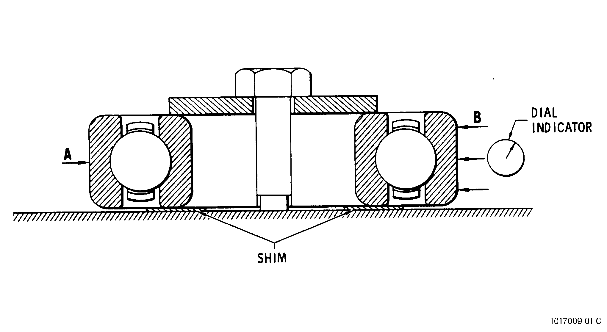
| (3) | Internal radial clearance. |
| Preferred Method. Use the following procedure to check internal radial clearance. See Figure 1. |
| (a) | Clamp inner ring to a surface plate, using a shim between the ring and the plate. Ordinary writing paper or newsprint 0.002-0.003 inch (0.05-0.08 mm) thick makes a satisfactory shim for small bearings; 2-3 thicknesses should be used for large bearings. |
| (b) | Place the spindle of a sensitive dial indicator radially against the surface of the outer race at the circumferential centerline. Press the outer race in direction A( Figure 1) release pressure, and reapply several times while intermittently turning the outer race back and forth circumferentially a small amount to seat the rolling elements. |
| (c) | While continuing to hold gentle pressure in direction A, move the outer race up and down several times until the dial indicator repeats its maximum reading consistently. Record the maximum indicator reading. |
| (d) | Without rotating the outer race from its original position, press it in direction B, release pressure, and reapply several times while intermittently turning it back and forth circumferentially a small amount to reseat the rolling elements. |
| (e) | While continuing to hold gentle pressure in direction B, move the outer race up and down several times until the dial indicator repeats its minimum reading consistently. Record the minimum indicator reading. |
| (f) | Repeat steps 2 through 5 with the outer race turned120 degrees from its original position with respect to the inner race, and again with the outer race turned 240 degrees from its original position. Average the 3 sets of readings; the average must be within the limits specified in the Engine/Shop Manual for internal radial clearance. |
| Alternate Method. Using a standard radial-play tester, check radial clearance at 3 points approximately 60 degrees apart. Use loading specified in the Engine/Shop Manual (Table of Bearing Limits in the Inspection Section). The average of the 3 readings must be within the limits specified in the Engine/Shop Manual. |
| C. | Supplementary Testing. |
| (1) | The following tests may be used to supplement the inspection procedures described in this section, particularly for nonseparable bearings. |
| (2) | A bearing analyzer can be used to check bearings for defects. Use Bearing Inspection Incorporated Model BA-20-3 or equivalent. Follow the manufacturers instructions. |
| NOTE: |
|
| (3) | The following tests depend upon the experience and judgment of the inspector for their validity; hence, only thoroughly experienced personnel should perform them. In general, proceed as follows: |
| (a) | Using a new bearing as a guide, check the wear on the bearings by feeling the end-play, radial play, and rock. End-play is felt by holding the inner race in one hand, and the outer race in the other, then alternating pushing together and pulling apart along the axis of the bearing, being careful to avoid tilting either ring with respect to the other. |
| (b) | Check radial play by applying pressure on the bore and outside surface, perpendicular to the axis of the bearing. Check each bearing at several points. |
| (c) | Feel rock by tilting one race relative to the other. Check several directions. A slight increase in internal clearance is not cause for rejection. |
| (d) | Make sure that the bearing is oiled, then slowly rotate the outer race while holding the inner race stationary and vertical. Check several times, with a different part of the inner race at the top each time. Any rough running bearings should be recleaned( TASK 70-22-01-110-013, Special Cleaning Procedure No. 1 - Cleaning of Bearings), relubricated, and rechecked. If the bearing continues to run roughly, reject it. |