| GENX-1B CLEANING,INSPECTION,AND REPAIR MANUAL | Dated: 09/05/2022 | |
| CIR 72-21-01 , REPAIR 001 | ||
| FORWARD FAN CONTAINMENT CASE ASSEMBLY - REPAIR - FORWARD ACOUSTIC LINER FACESHEET REPAIR | ||
| GENX-1B CLEANING,INSPECTION,AND REPAIR MANUAL | Dated: 09/05/2022 | |
| CIR 72-21-01 , REPAIR 001 | ||
| FORWARD FAN CONTAINMENT CASE ASSEMBLY - REPAIR - FORWARD ACOUSTIC LINER FACESHEET REPAIR | ||
| * * * FOR ALL |
| TASK 72-21-01-300-803 |
| 1 . | Repair for the Forward Fan Containment Case Assembly. |
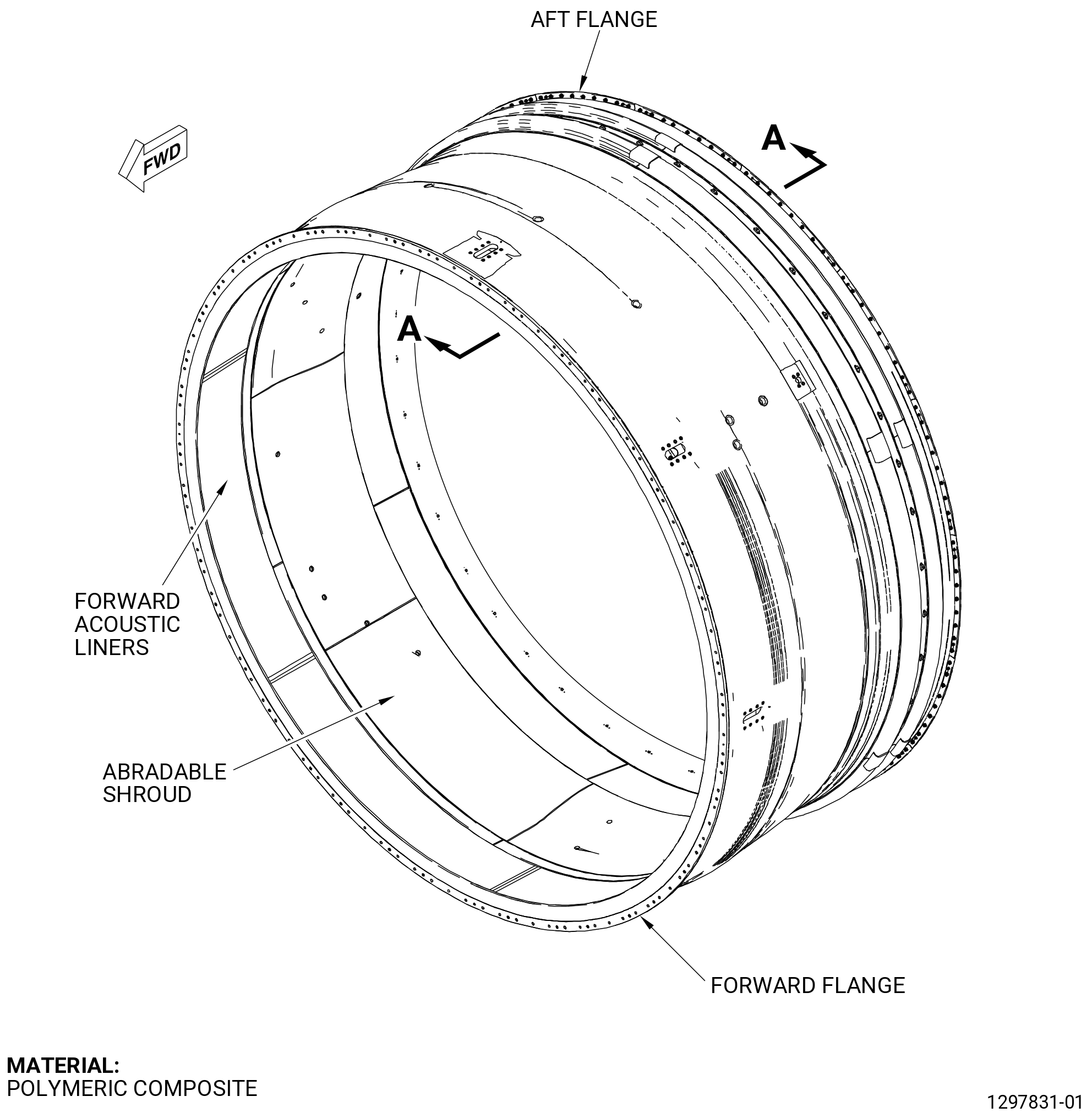
| A. | This procedure gives instructions to repair the fan stator forward acoustic liner (acoustic liner) by replacing the facesheet and the honeycomb. Refer to Figure 901. |
| B. | The following Maximum Repairable limits apply to this repair: |
| NOTE: |
|
| NOTE: |
|
| (4) | Visual Inspection. |
| (i) | Do an inspection of the forward acoustic liner for: |
| 1 | Cracks: |
| Maximum repairable limit: |
|
| 2 | Nicks and scratches on the face sheet: |
| Maximum repairable limit: |
|
| 3 | Tears and cuts on the face sheet: |
| Maximum repairable limit: |
|
| 4 | Delaminations on the face sheet: |
| Maximum repairable limit: |
|
| 5 | Punctures and holes on the face sheet: |
| Maximum repairable limit: |
|
| C. | The subsequent table gives a list of the part numbers that are applicable to this repair. All part numbers are applicable to all paragraphs unless specified differently. |
| NOTE: |
|
|
|||||||||||||||||||||||||||||||||||||||||||||||||
| D. | Proprietary/Complex Process Statement. |
| (1) | None. |
| 2 . | Tools, Equipment, and Materials. |
| NOTE: |
|
| A. | Tools and Equipment. |
| (1) | Special Tools. None. |
| (2) | Standard Tools and Equipment. None. |
| (3) | Locally Manufactured Tools. |
|
| B. | Consumable Materials. |
| C. | Referenced Procedures. |
|
| D. | Expendable Parts. None. |
| E. | SPD Information. |
|
| (1) | Locally Manufactured SPD. |
|
| F. | Special Solutions. None. |
| G. | Test Specimens. None. |
| 3 . | Dimensional Information. |
| Subtask 72-21-01-220-046 |
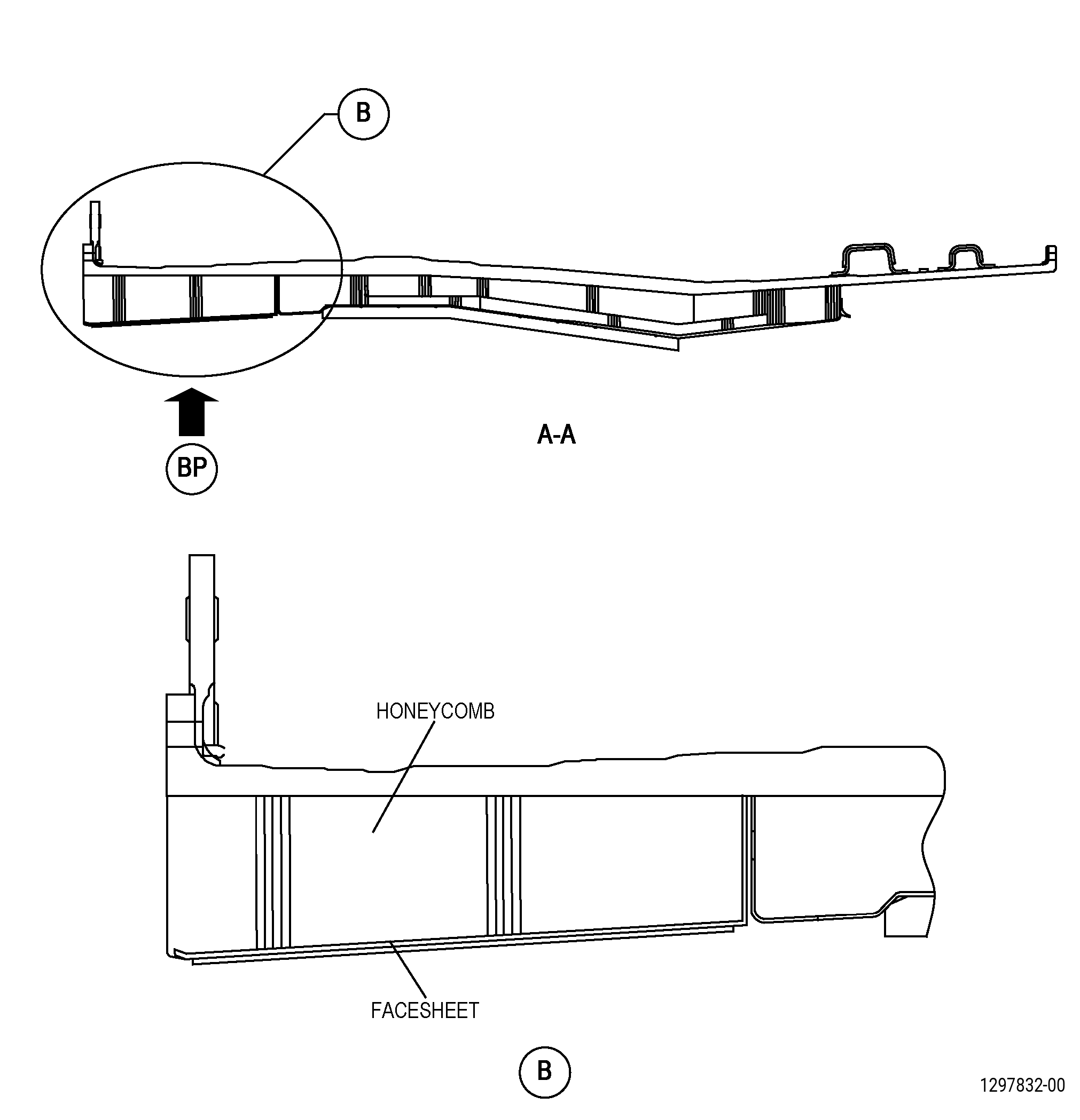
| A. | Refer to Figure 906 for specified dimensions and locations. |
| NOTE: |
|
| 4 . | Setup Information. |
| None. |
| 5 . | Procedure. |
| Subtask 72-21-01-930-002 |
| NOTE: |
|
| A. | If necessary, make the tools that follow: |
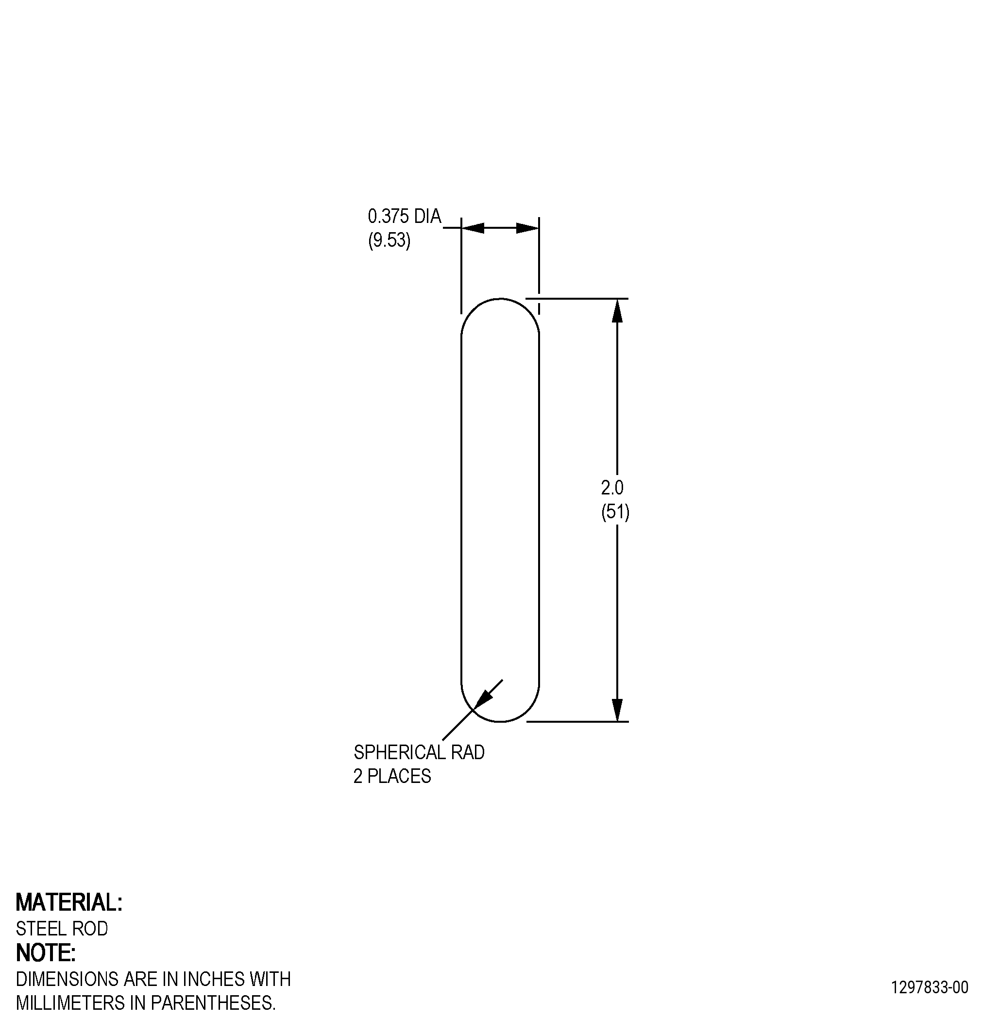
| (1) | Make a steel rod. Refer to Figure 902. |
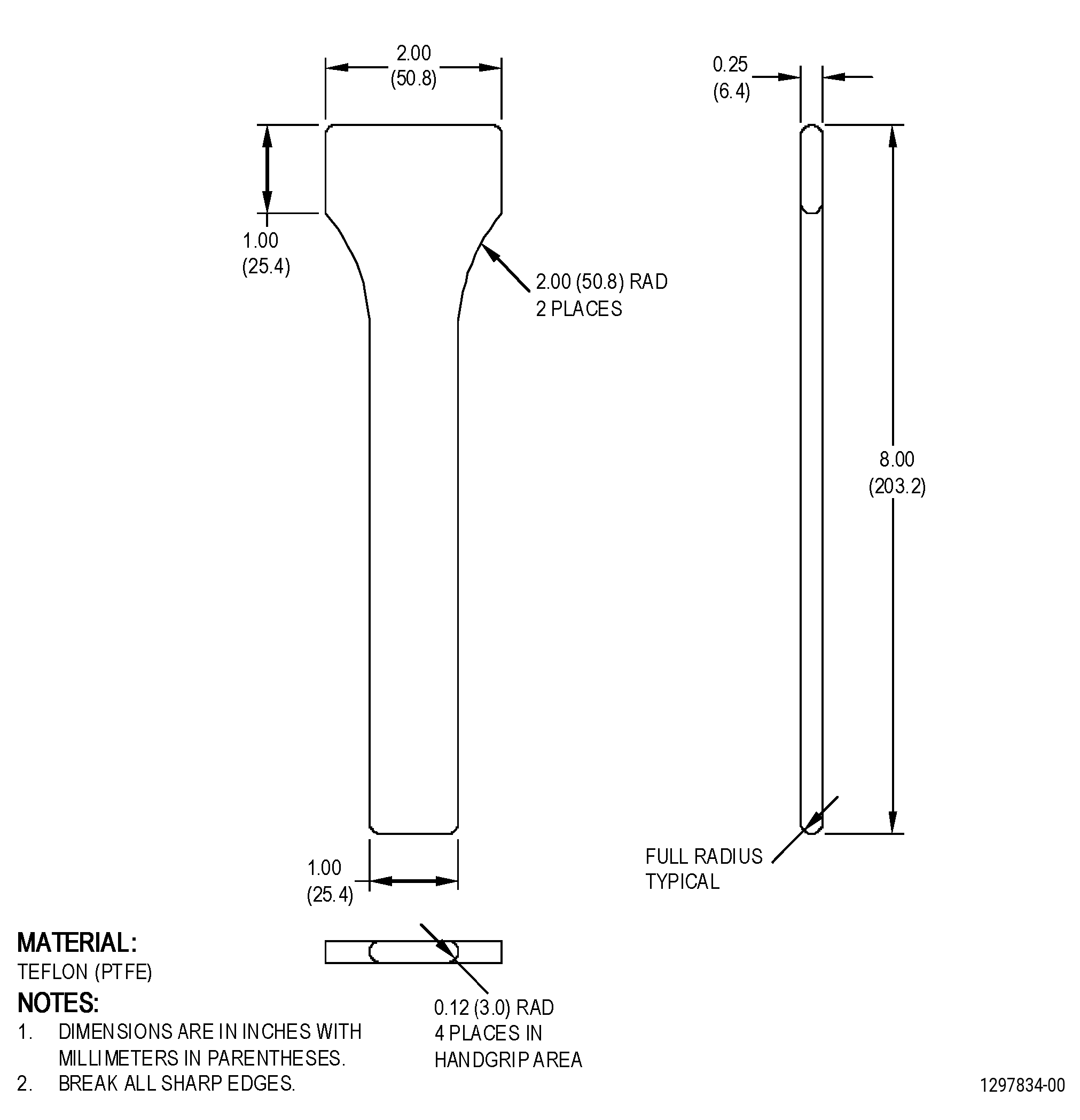
| (2) | Make a Teflon spatula. Refer to Figure 903. |
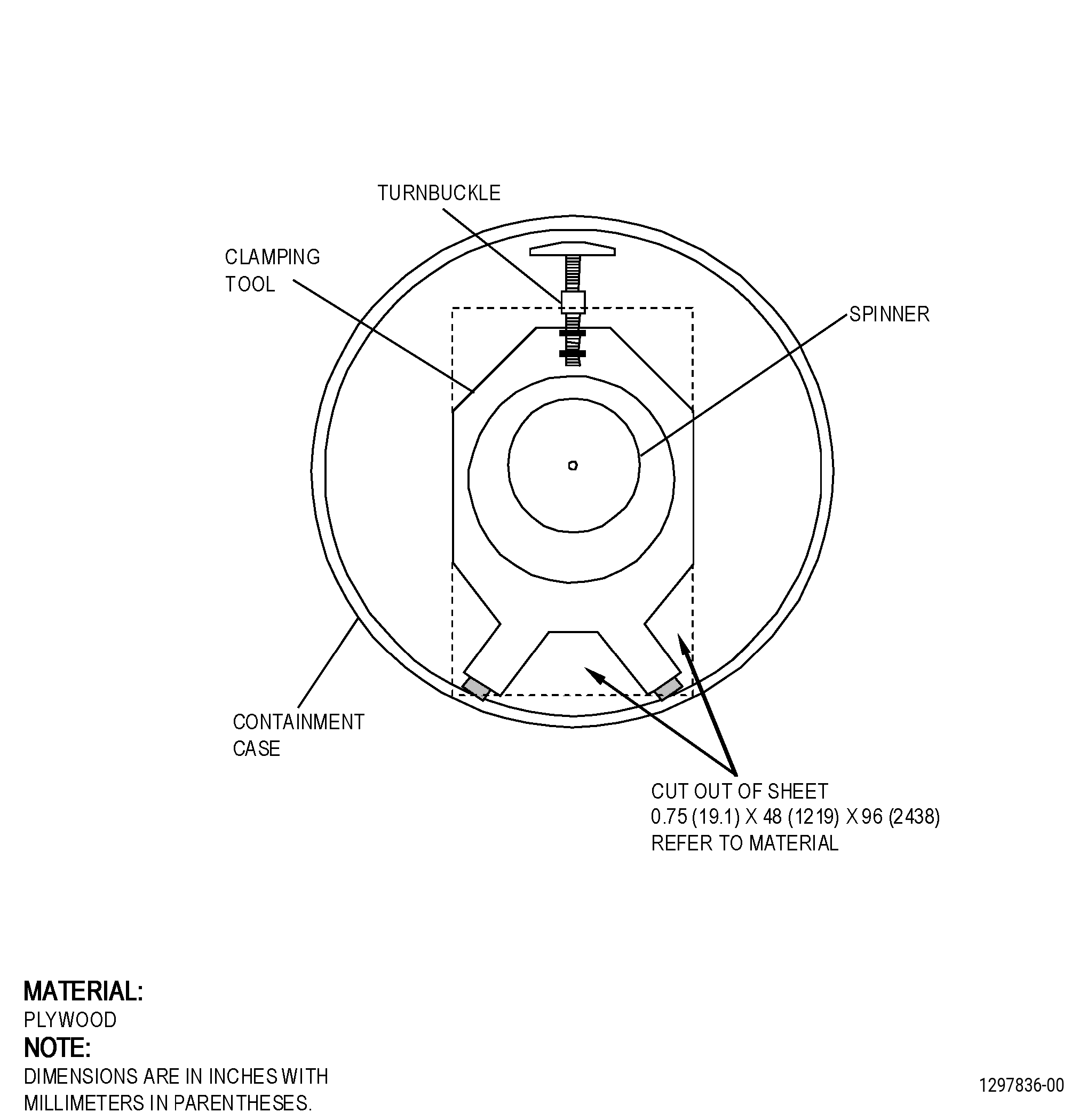
| (3) | Make a clamping tool. Refer to Figure 904. |
| Subtask 72-21-01-220-047 |
| B. | Do an inspection of the acoustic liner damaged area. Refer to Figure 901, and as follows: |
| (1) | Remove the loose or damaged facesheet and the honeycomb material. |
| NOTE: |
|
| Subtask 72-21-01-350-015 |
| (2) | Clean the acoustic liner damaged area. Refer to TASK 70-46-01-350-030 (MASKING AND CLEANING OF EPOXY AND POLYESTER MATRIX THERMOSETTING COMPOSITE MATERIALS), and as follows: |
| (a) | Use Composite Cleaning Method No. 4 or Composite Cleaning Method No. 5. |
| Subtask 72-21-01-210-002 |
| (3) | Do a check for disbond and delamination as follows: |
| (a) | Tap the facesheet of the acoustic liner lightly with the steel rod and listen to the sound. |
| NOTE: |
|
| (b) | If you hear a solid click, there is no disbond or delamination. |
| (c) | If you do not hear a solid click, there is a disbond or delamination. |
| (d) | Put a mark around the areas that are disbonded or delaminated. Refer to TASK 70-16-00-350-001 (MARKING PRACTICES), and TASK 70-16-02-350-017 (TEMPORARY MARKING), and as follows: |
| 1 | Use a C05-003 marking pen. |
| (e) | Make a template of the mark around the damaged area as follows: |
| 1 | Make the shape of the template in a geometric shape that is easy to cut. |
| Subtask 72-21-01-140-006 |
| WARNING: |
|
| C. | Prepare the acoustic liner segment for repair as follows: |
| WARNING: |
|
| CAUTION: |
|
| (1) | Remove the damaged area of the facesheet as follows: |
| (a) | Cut the acoustic liner as follows: |
| 1 | Cut along the mark that is around the damaged area. |
| 2 | Use an air driven, right angle drive grinder with a small diameter cut-off disk. |
| 3 | Do not cut into the honeycomb. |
| (b) | Use needle-nosed pliers to remove the damaged facesheet as follows: |
| 1 | Start at a corner or an edge and carefully pull the cut-out part of the facesheet from the acoustic liner. |
| (2) | If the honeycomb is damaged, remove the honeycomb down to the fan case as follows: |
| WARNING: |
|
| WARNING: |
|
| CAUTION: |
|
| (a) | Use a razor knife or hand held router to cut the honeycomb the same size as the hole in the facesheet. |
| (b) | Use needle nosed pliers to remove the honeycomb from the repair area. |
| (c) | Remove all the loose and crushed material. |
| WARNING: |
|
| (d) | Use C10-141 120-180 grit abrasive paper to remove the remaining honeycomb and make the surface of the fan case rough. |
| Subtask 72-21-01-220-048 |
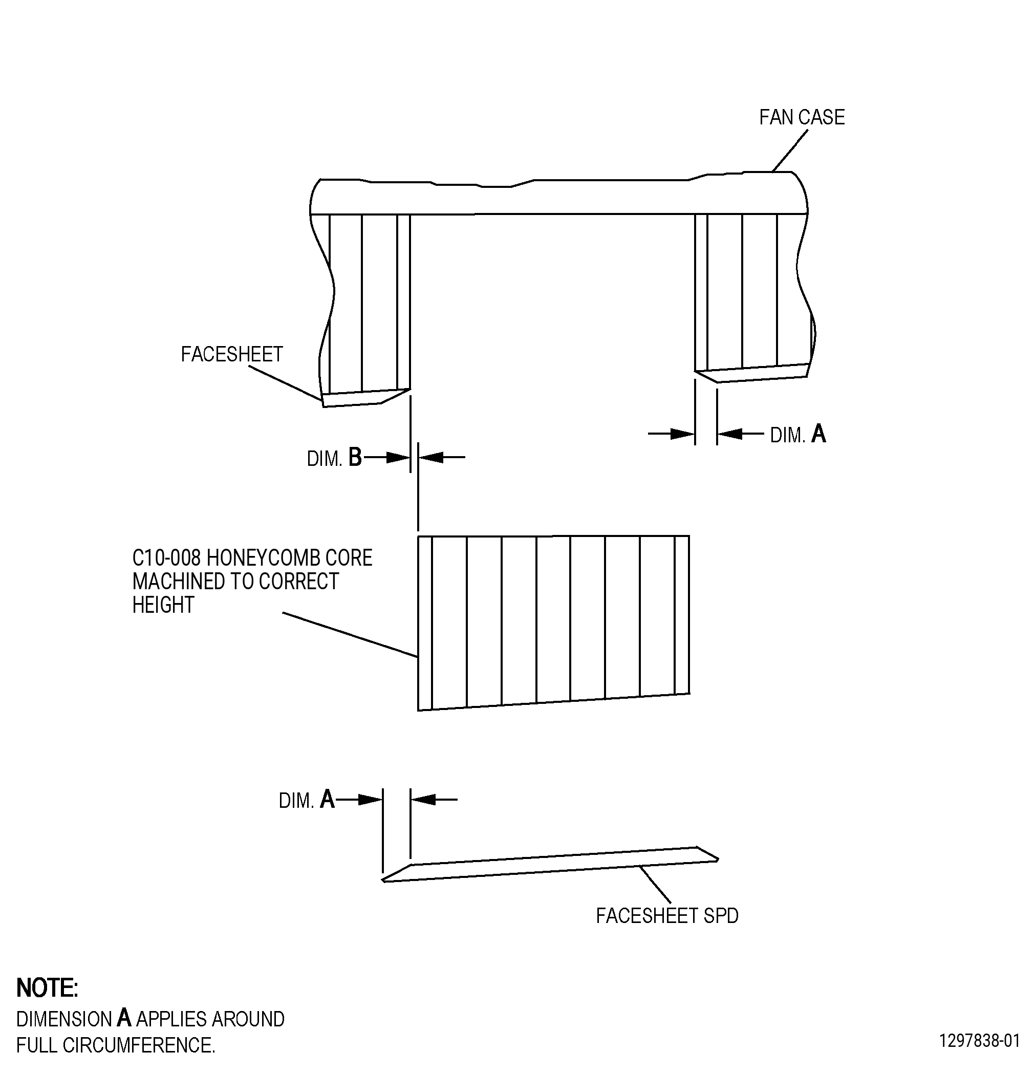
| (3) | Chamfer the edges of the facesheet for a distance of dimension A around the hole in the facesheet. Refer to Subtask 72-21-01-220-046 (paragraph 3.A, Dimensional Information), and Figure 906. |
| (4) | Do an inspection of the repair area and do as follows: |
| (a) | Do an inspection of the repair area for water or oil and do as follows: |
| 1 | If necessary, remove the water or oil. Refer to TASK 70-46-02-360-002 (DRYING OF THERMOSETTING COMPOSITE MATERIALS). |
| (b) | Do an inspection of the fan case and do as follows: |
| 1 | If you find damage to the fan case in the repair area, the forward acoustic liners are not repairable by this procedure. |
| Subtask 72-21-01-160-006 |
| (5) | Clean the repair area as follows: |
| WARNING: |
|
| (a) | Blow the unwanted debris from the repair area with clean, dry, compressed air that contains no oil. |
| Subtask 72-21-01-350-016 |
| (b) | Clean the repair area. Refer to TASK 70-46-01-350-030 (MASKING AND CLEANING OF EPOXY AND POLYESTER MATRIX THERMOSETTING COMPOSITE MATERIALS), and as follows: |
| 1 | Use Composite Cleaning Method No. 4 or Composite Cleaning Method No. 5. |
| Subtask 72-21-01-350-017 |
| (c) | Apply masking to the areas that you will not repair. Refer to TASK 70-46-01-350-030 (MASKING AND CLEANING OF EPOXY AND POLYESTER MATRIX THERMOSETTING COMPOSITE MATERIALS), and as follows: |
| NOTE: |
|
| 1 | Use Composite Masking Method No. 3. |
| (d) | Apply masking to the areas that you will repair. Refer to TASK 70-46-01-350-030 (MASKING AND CLEANING OF EPOXY AND POLYESTER MATRIX THERMOSETTING COMPOSITE MATERIALS), and as follows: |
| NOTE: |
|
| 1 | Use Composite Masking Method No. 4. |
| Subtask 72-21-01-350-018 |
| D. | Repair the acoustic liner damaged area. Refer to TASK 72-21-01-300-803 (paragraph 2.E., SPD Information), Figure 906, and do as follows: |
| (1) | Prepare the facesheet SPD for installation as follows: |
| (a) | Find the area of the facesheet that is the same as the cut-out area on the acoustic liner as follows: |
| 1 | Use the template and find the area of the facesheet that is the same as the cut-out area on the acoustic liner. |
| 2 | Make sure the holes of the SPD are aligned to agree with the holes of the acoustic panel. |
| (b) | Put a mark around the area on the facesheet to cut out. Refer to TASK 70-16-00-350-001 (MARKING PRACTICES), and TASK 70-16-02-350-017 (TEMPORARY MARKING), and as follows: |
| 1 | Use a C05-003 marking pen. |
| Subtask 72-21-01-140-007 |
| WARNING: |
|
| (c) | Make the facesheet SPD as follows: |
| WARNING: |
|
| 1 | Use a right-angle grinder with a cut-off disk to cut the facesheet SPD. |
| WARNING: |
|
| 2 | Cut the facesheet SPD dimension A larger in all directions than the mark on the facesheet. |
| WARNING: |
|
| 3 | Use a small disk sander to chamfer the edges of the facesheet to agree with the chamfer on the acoustic liner. |
| Subtask 72-21-01-350-019 |
| (2) | If necessary, prepare the honeycomb SPD for installation as follows: |
| WARNING: |
|
| (a) | Make the honeycomb SPD. Refer to Figure 906, and as follows: |
| 1 | Use C10-008 honeycomb core. |
| 2 | Machine the honeycomb SPD to the correct thickness for the repair area. |
| WARNING: |
|
| 3 | Cut the honeycomb SPD to get the correct fit into the cut-out area in the liner segment. |
| 4 | Use a razor knife or grinder with a cut-off disk to cut the honeycomb SPD. |
| 5 | The maximum distance permitted between the facesheet and the honeycomb in the acoustic liner is dimension B. |
| Subtask 72-21-01-350-020 |
| (3) | Do a trial fit of the facesheet SPD and the honeycomb SPD into the repair area as follows: |
| NOTE: |
|
| (a) | Remove the masking from the repair area. |
| (b) | Do a trial fit of the honeycomb SPD and facesheet SPD into the acoustic liner as follows: |
| 1 | Install the honeycomb SPD and the facesheet SPD into the repair area. |
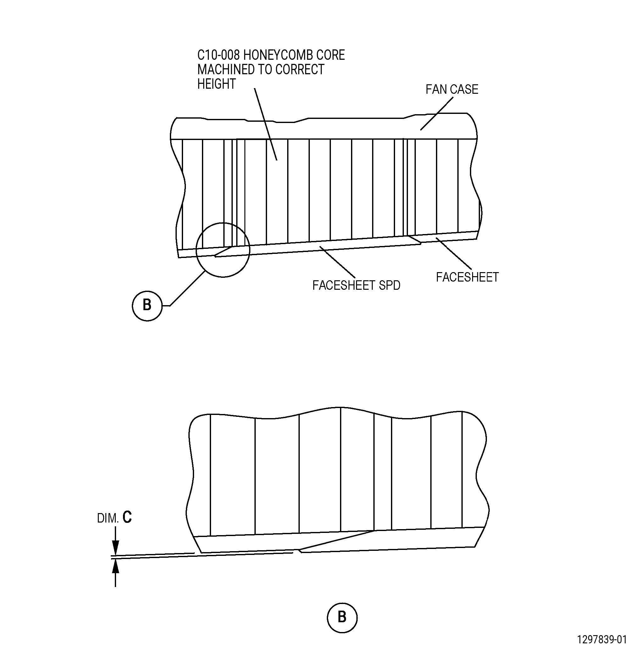
| 2 | Measure the differences in contour between the facesheet SPD and the acoustic liner facesheet and do as follows: |
| a | The maximum difference permitted is dimension C. |
| 3 | Make sure that surface is smooth and there is no step between the two surfaces. |
| 4 | If the repair covers the forward edge of the perforated area of the facesheet, adjust the thickness of the honeycomb SPD to permit a change in thickness of the facesheet SPD at that location. |
| (c) | Remove the honeycomb SPD and facesheet SPD from the acoustic liner. |
| Subtask 72-21-01-350-021 |
| (d) | Clean the repair areas of the acoustic liner and the facesheet SPD. Refer to TASK 70-46-01-350-030 (MASKING AND CLEANING OF EPOXY AND POLYESTER MATRIX THERMOSETTING COMPOSITE MATERIALS), and as follows: |
| 1 | Use Composite Cleaning Method No. 4 or Use Composite Cleaning Method No. 5. |
| (e) | Clean the honeycomb SPD. Refer to TASK 70-46-01-350-030 (MASKING AND CLEANING OF EPOXY AND POLYESTER MATRIX THERMOSETTING COMPOSITE MATERIALS), and as follows: |
| 1 | Use Honeycomb Cleaning Method No. 3. |
| 2 | Use clean C10-139 cotton gloves when you touch the clean parts. |
| (4) | Put the honeycomb SPD and facesheet SPD into separate clean, new plastic bags until you will use the parts. |
| Subtask 72-21-01-360-009 |
| WARNING: |
|
| WARNING: |
|
| CAUTION: |
|
| (5) | Alternative Procedure Available. Prepare the C01-011 paste adhesive to bond the honeycomb SPD and facesheet SPD to the acoustic liner as follows: |
| (a) | Make an estimate of the amount of C01-011 paste adhesive that will be necessary. |
| (b) | Mix the C01-011 paste adhesive in a clean metal or uncoated paper container. |
| (c) | Mix the quantities in the ratio as follows: |
| 1 | Part A (Resin (Thixotropic gray material)) - 100 parts by weight. |
| 2 | Part B (Catalyst (Liquid)) - 33 parts by weight. |
| (d) | Mix the resin and catalyst until there are no streaks in the adhesive. |
| NOTE: |
|
| Subtask 72-21-01-360-010 |
| WARNING: |
|
| CAUTION: |
|
| (5).A. | Alternative Procedure. Prepare the C01-155 Hysol EA-9394 paste adhesive to bond the honeycomb SPD and facesheet SPD to the acoustic liner as follows: |
| (a) | Refer to the manufacturer’s instructions to mix Part A and Part B. |
| Subtask 72-21-01-360-011 |
| (6) | If necessary, install the honeycomb SPD into the repair cavity as follows: |
| (a) | Remove the masking from the repair area. |
| (b) | Remove the honeycomb SPD from the plastic bag. |
| (c) | Use a C10-108 brush to C01-011 paste adhesive to the fan case and honeycomb SPD as follows: |
| 1 | Apply C01-011 paste adhesive to the fan case surface. |
| 2 | Rub the adhesive thoroughly on the surface. Apply a thin layer approximately 0.05 inch (1.3 mm) in thickness. |
| 3 | If necessary, use a Teflon spatula, Figure 903, to make the adhesive level. |
| 4 | Apply C01-011 paste adhesive to the bottom of the honeycomb SPD. |
| (d) | Put the honeycomb SPD into the hole in the acoustic liner as follows: |
| 1 | Mix the C01-161 abradable seal material. Follow manufacturer’s instructions, and do as follows: |
| a | Mix Part A and Part B separately to get a constant appearance. |
| b | Mix Part A and Part B thoroughly until there are no streaks. |
| NOTE: |
|
| 2 | Use a C10-108 brush to apply the C01-161 abradable seal material to the sidewalls of the repair area as follows: |
| a | Make the C01-161 abradable seal material layer approximately 0.05 inch (1.3 mm) in thickness. |
| 3 | Use a C10-108 brush to apply the C01-161 abradable seal material to sidewalls of honeycomb SPD as follows: |
| a | Make the C01-161 abradable seal material layer approximately 0.05 inch (1.3 mm) in thickness. |
| 4 | Push the honeycomb SPD into the repair area. |
| 5 | If necessary, use a dry C10-182 cleaning cloth to remove the unwanted C01-161 abradable seal material from the repair area. |
| (7) | Install the facesheet SPD as follows: |
| (a) | Apply the C01-011 paste adhesive as follows: |
| 1 | Apply the C01-011 paste adhesive to the top of the honeycomb SPD as follows: |
| a | Use a C10-108 brush. |
| b | Make the adhesive layer approximately 0.05 inch (1.3 mm) in thickness. |
| 2 | Apply the C01-011 paste adhesive to the chamfered areas of the acoustic liner facesheet and the inside surface and chamfered area of the facesheet SPD as follows: |
| a | Use a C10-108 brush. |
| b | Make the adhesive layer approximately 0.05 inch (1.3 mm) in thickness. |
| (b) | Put the facesheet SPD on the repair area and do as follows: |
| 1 | Make sure that the small holes in the facesheet SPD are aligned with the acoustic liner. |
| 2 | Make sure the chamfered area on the facesheet SPD and the acoustic liner facesheet touch on all of the tapered surfaces. |
| 3 | Use a dry C10-182 cleaning cloth to remove the unwanted paste adhesive. |
| CAUTION: |
|
| (c) | Put a layer of C10-133 FEP film on the repair area and do as follows: |
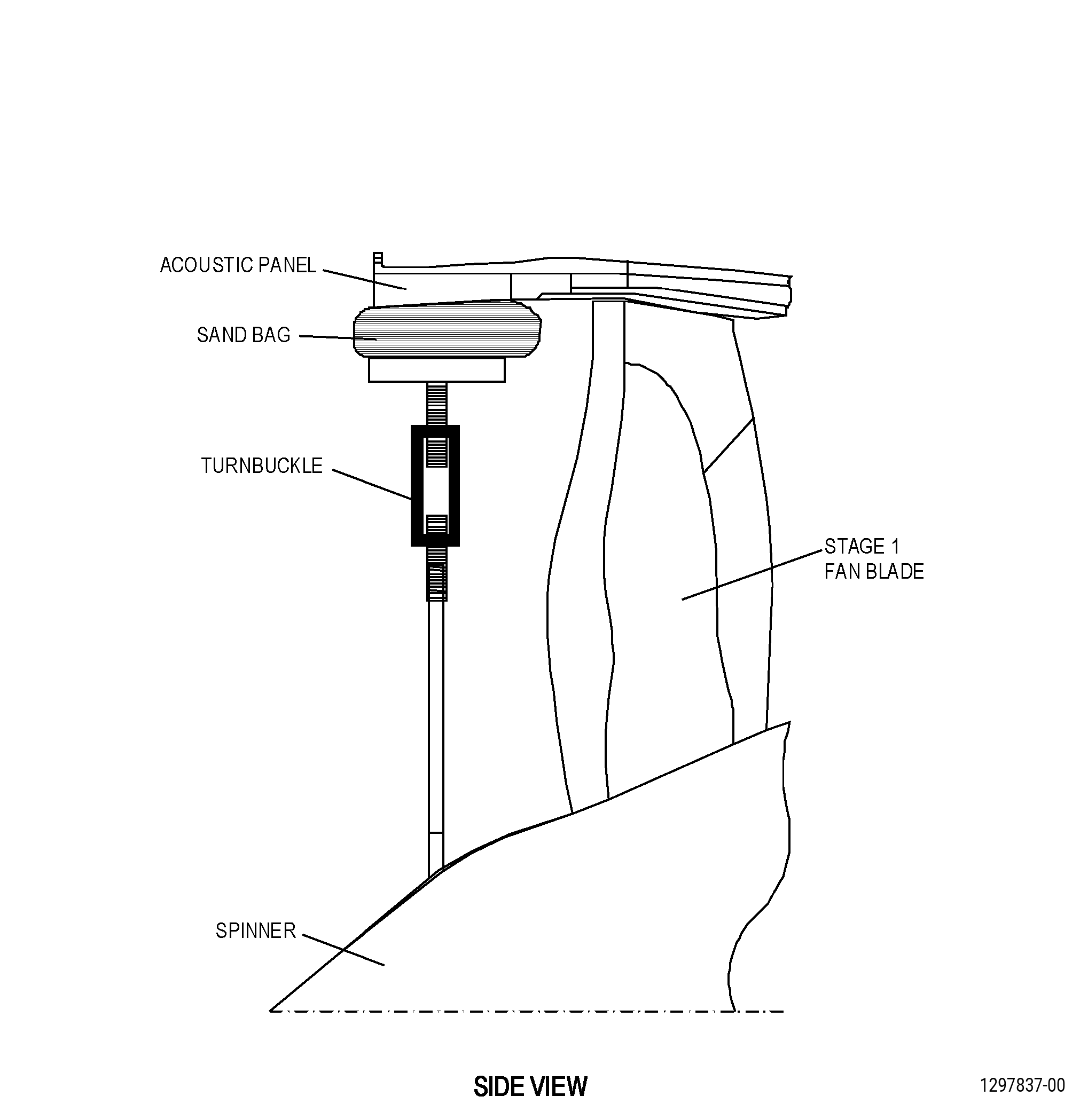
| 1 | Use a weight, turnbuckle spreader bar, or clamping tool to apply the same pressure on all of the repair area. Refer to Figure 905. |
| NOTE: |
|
| 2 | The quantity of weight necessary will depend on the repair area. |
| 3 | Apply a pressure of 2-5 psi (14-34 kPa) to the repair area. |
| NOTE: |
|
| NOTE: |
|
| (d) | Use a dry C10-182 cleaning cloth and a 0.045-0.055 inch (1.15-1.39 mm) diameter drill rod to remove the unwanted adhesive from the facesheet surface and from the small holes and as follows: |
| 1 | Move the weight and film as necessary while you do this step. |
| WARNING: |
|
| WARNING: |
|
| (e) | If necessary, fill the gap between the two acoustic liners as follows: |
| 1 | Make sure that there is a distance of 0.00-0.28 inch (0-7.1 mm) between the acoustic liners. |
| 2 | Prepare the C01-155 Hysol EA-9394 paste adhesive as follows: |
| a | Make an estimate of the amount of C01-155 Hysol EA-9394 paste adhesive that will be necessary. |
| b | Mix the adhesive as instructed by the manufacturer. |
| 3 | Use a Teflon spatula to fill the gap between acoustic liners with the mixed C01-155 Hysol EA-9394 paste adhesive. |
| (f) | Cure the repair area as follows: |
| 1 | Keep the fan case supported and do not remove the FEP film when there is an increase of pressure on the acoustic liner. |
| 2 | Keep the constant pressure on the repair area. |
| Subtask 72-21-01-360-012 |
| 3 | Alternative Procedure Available. Cure the paste adhesive for a minimum of 5 days at a temperature range of 65 to 85°F (18 to 29°C). |
| Subtask 72-21-01-360-013 |
| 3.A. | Alternative Procedure. Cure the paste adhesive for a minimum of 1 hour at a temperature range of 140 to 160°F (60 to 71°C). Refer to SAE ARP 5144 Heat Application for Thermosetting Resin Curing. |
| (g) | Remove the pressure and the FEP film from the repaired area. |
| (h) | Remove all the masking material. |
| Subtask 72-21-01-160-007 |
| WARNING: |
|
| E. | Clean the acoustic liner after repair as follows: |
| CAUTION: |
|
| (1) | Drill to remove the remaining adhesive from the holes in the facesheet as follows: |
| (a) | Use a pin vise and a 0.045-0.055 inch (1.15-1.39 mm) diameter drill bit. |
| Subtask 72-21-01-140-010 |
| WARNING: |
|
| (2) | Use C10-141 120-180 grit abrasive paper to remove the unwanted adhesive from the repair area. |
| Subtask 72-21-01-220-049 |
| F. | Do an inspection of the facesheet repaired area as follows: |
| (1) | Do an inspection of the bond line around the repair area as follows: |
| (a) | Voids and loose adhesive not permitted. |
| Subtask 72-21-01-210-003 |
| (2) | Do a check of the facesheet for delamination. Refer to Subtask 72-21-01-210-002 (paragraph 5.B.(3)). |
| Subtask 72-21-01-220-050 |
| (3) | Do an inspection of the contour as follows: |
| (a) | Measure the differences in contour between the facesheet SPD and the acoustic liner facesheet. The maximum difference permitted is 0.020 inch (0.50 mm). |
| (b) | Make sure that the surface is smooth and there is no step between the two surfaces. |
| Subtask 72-21-01-350-022 |
| NOTE: |
|
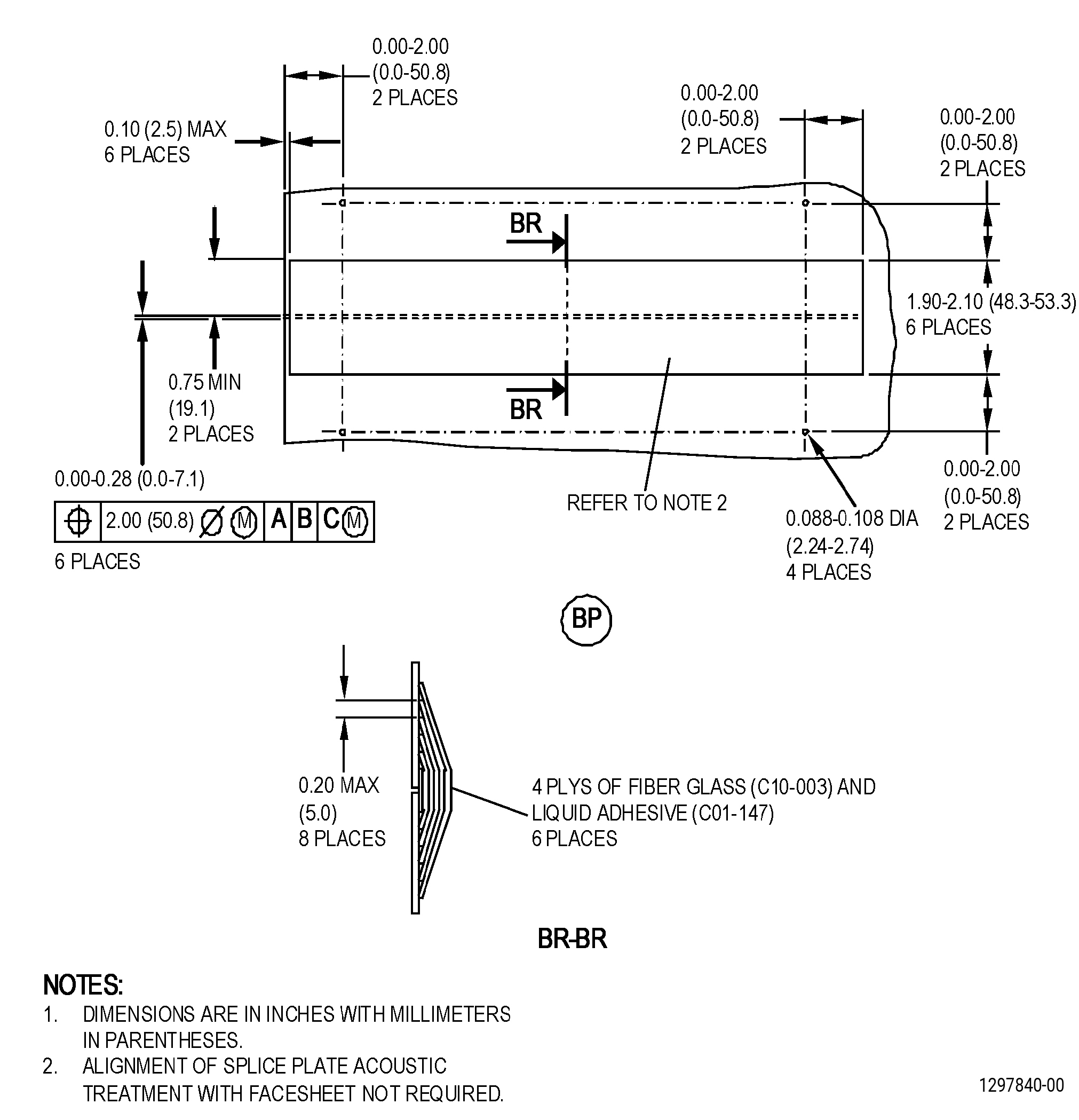
| G. | If necessary, install the splice plate SPD on the repair area. Refer to Figure 907 and as follows: |
| (1) | Apply masking to the areas that you will not repair. Refer to TASK 70-46-01-350-030 (MASKING AND CLEANING OF EPOXY AND POLYESTER MATRIX THERMOSETTING COMPOSITE MATERIALS), and as follows: |
| NOTE: |
|
| (a) | Use Composite Masking Method No. 3. |
| Subtask 72-21-01-140-012 |
| WARNING: |
|
| (2) | If necessary, remove the damaged splice plate as follows: |
| CAUTION: |
|
| (a) | Use an air driven, right angle grinder with a sanding disk. |
| WARNING: |
|
| (b) | Blow the unwanted debris from the repair area with clean, dry, compressed air that contains no oil. |
| Subtask 72-21-01-350-023 |
| (c) | Clean the repair areas of the acoustic liner. Refer to TASK 70-46-01-350-030 (MASKING AND CLEANING OF EPOXY AND POLYESTER MATRIX THERMOSETTING COMPOSITE MATERIALS), and as follows: |
| 1 | Use Composite Cleaning Method No. 4 or Use Composite Cleaning Method No. 5. |
| Subtask 72-21-01-350-024 |
| (3) | Make a splice plate SPD as follows: |
| (a) | Put a layer of C10-142 polyester film on a work table. |
| WARNING: |
|
| (b) | Cut four plies of C10-003 glass fabric of sufficient size for the repair area. |
| (c) | Put the C10-003 glass fabric on the C10-142 polyester film. |
| Subtask 72-21-01-360-014 |
| WARNING: |
|
| WARNING: |
|
| CAUTION: |
|
| (d) | Prepare the C01-147 liquid adhesive, and do as follows: |
| 1 | Make an estimate of the quantity of C01-147 liquid adhesive that you will use. |
| 2 | Use a clean metal or paper container that has no wax. |
| 3 | Weigh sufficient quantities of each component to the proportions that follow: |
| a | Part A (adhesive)- 100 units. |
| b | Part B (catalyst) - 30 units. |
| 4 | Mix the adhesive components until there are no streaks of the two components. |
| NOTE: |
|
| (e) | Rub the C01-147 liquid adhesive on the C10-003 glass fabric with a new and clean C10-108 brush. |
| (f) | Put a second piece of new C10-142 polyester film on top of the C10-003 glass fabric and C01-147 liquid adhesive. |
| (g) | Use the Teflon spatula to push the C01-147 liquid adhesive into the C10-003 glass fabric until the two sides are fully wet with C01-147 liquid adhesive. |
| (h) | Use the Teflon spatula to remove all the caught air and the unwanted liquid adhesive. |
| (i) | Remove one side of the polyester film or vacuum bag film from the first ply. |
| (j) | Apply a layer of C01-147 liquid adhesive of approximate 0.010 inch (0.25 mm) in thickness on the repair area as follows: |
| 1 | Use a new, clean C10-108 brush to apply the C01-147 liquid adhesive. |
| (k) | Put the C10-003 glass fabric ply with the side that you removed from the C10-142 polyester film on the repair area. |
| (l) | Remove the top piece of polyester film or vacuum bag film from the first C10-003 glass fabric ply. |
| Subtask 72-21-01-360-015 |
| (m) | Apply a layer of C01-147 liquid adhesive of approximate 0.010 inch (0.25 mm) in thickness on the first piece of C10-003 glass fabric as follows: |
| 1 | Use a new, clean C10-108 brush to apply the C01-147 liquid adhesive. |
| 2 | Use the Teflon spatula to remove all the caught air and make the C01-147 liquid adhesive smooth. |
| Subtask 72-21-01-350-027 |
| (n) | Put the next piece of C10-003 glass fabric on the previous ply as follows: |
| 1 | Remove the polyester film or the vacuum bag film from one side of the next piece of C10-003 glass fabric. |
| 2 | Use the Teflon spatula to remove all the caught air and make the C01-147 liquid adhesive smooth. |
| 3 | Remove the polyester film from the second side of the ply. |
| Subtask 72-21-01-360-016 |
| (o) | Do Subtask 72-21-01-360-015 (paragraph 5.G.(3)(m)) thru Subtask 72-21-01-350-027 (paragraph 5.G.(3)(n)) again for the remaining plies. |
| Subtask 72-21-01-360-017 |
| (p) | Alternative Procedure Available. Let the mixed adhesive cure for 3-5 days at a minimum temperature of 65°F (18°C). |
| Subtask 72-21-01-360-018 |
| WARNING: |
|
| (p).A. | Alternative Procedure. Let the mixed adhesive cure for 8 hours at a minimum temperature of 65°F (18°C) followed by a minimum of 1 hour at a temperature range of 180 to 200°F (82 to 93°C). Refer to SAE ARP 5144 Heat Application for Thermosetting Resin Curing. |
| (q) | Remove the polyester film. |
| Subtask 72-21-01-140-011 |
| WARNING: |
|
| (r) | Sand the slice plate SPD to get a smooth matte finish as follows: |
| NOTE: |
|
| 1 | Use C10-141 120-180 grit abrasive paper. |
| Subtask 72-21-01-160-008 |
| WARNING: |
|
| (s) | Remove the dust from the SPD facesheet with clean, dry, compressed air that contains no oil. |
| Subtask 72-21-01-350-026 |
| (4) | Remove all the masking material from the repair area. |
| Subtask 72-21-01-350-032 |
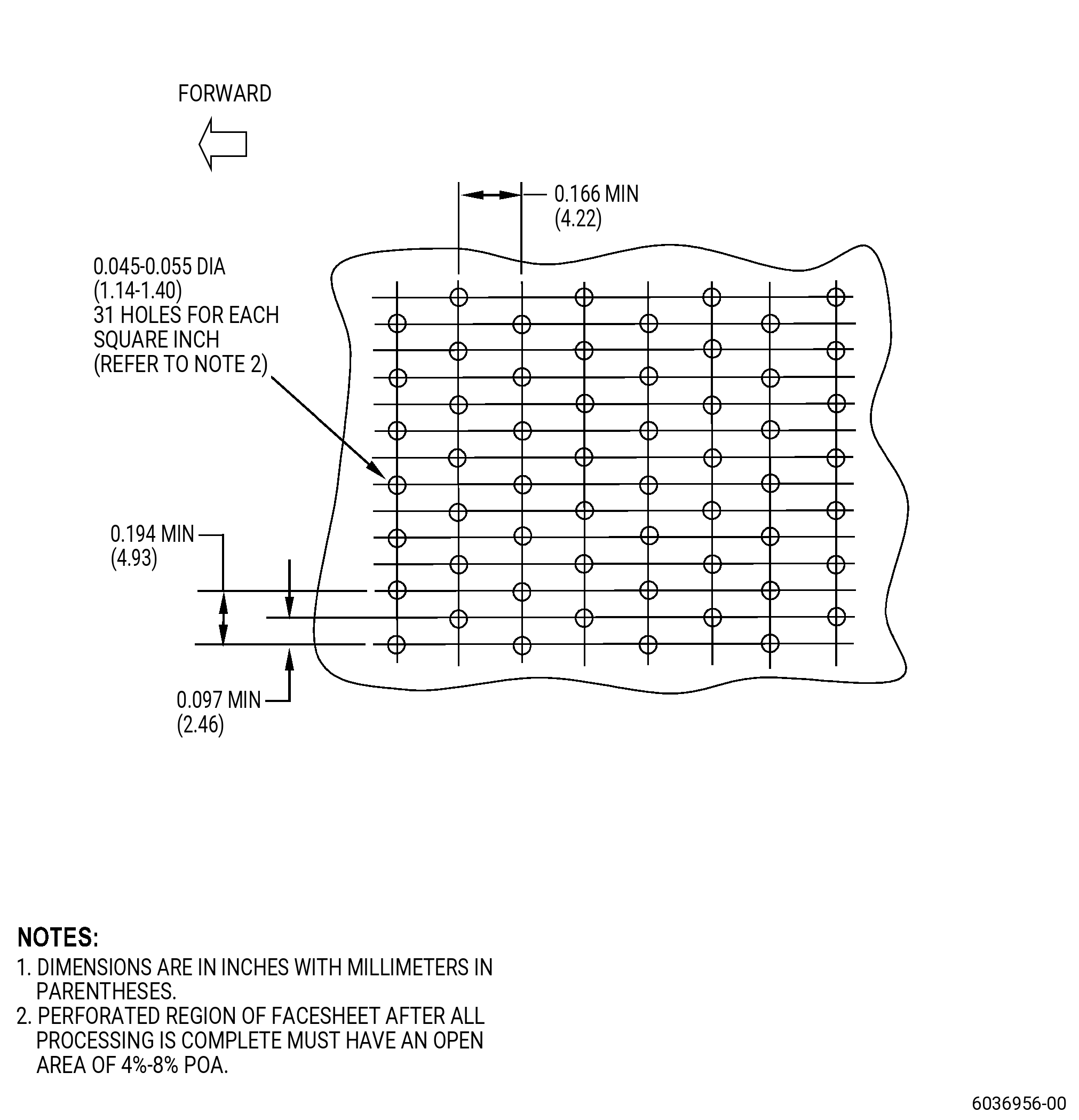
| H. | Drill an acoustic pattern into the splice plate at the repair area as follows: |
| (1) | Drilling must penetrate the splice plate and underlying facesheet. Refer to Figure 908 and do as follows: |
| (a) | Apply C10-136 tape to the facesheet and adjacent areas to protect the facesheet from the drill contact damage during the repair. |
| (b) | Use a drill bit of 0.045-0.055 inch (1.15-1.39 mm) in diameter. |
| (c) | Install the drill bit into the cordless drill until only 0.125-0.145 inch (3.18-3.68 mm) sticks out. |
| (d) | Change the drill bit after drilling 250 holes to reduce the risk of drill breakage. |
| (e) | Splice plate holes do not have to be aligned with the pre-existing holes on the facesheet, however they must follow the hole pattern. Refer to Figure 908. |
| NOTE: |
|
| (f) | Drill the first hole and check the depth to make sure that the drill bit goes through the splice plate and facesheet only. Do not drill into the honeycomb below. |
| (g) | Drill the holes that remain. Keep the drill level and straight. |
| (h) | Do a visual inspection of the drill bit after each hole is drilled. If the bit breaks, do not continue drilling holes and as follows: |
| 1 | If the drill bit can be removed, do as follows: |
| a | Remove the broken bit with pliers. |
| 2 | If the broken drill bit cannot be removed with pliers and/or if the bit breaks and falls into an underlying honeycomb cell, do as follows: |
| a | Push the bit through the hole into the underlying honeycomb cell. |
| b | Temporarily mark the hole so that the location in the hole pattern is not lost. |
| c | Inject C01-147 liquid adhesive into the same hole until the resin fills the underlying honeycomb cell and weeps out of the adjacent holes. Temporarily plug adjacent weep holes with C10-136 tape, so resin does not run onto adjacent surfaces. Continue injecting resin until no more resin weeps from the adjacent holes. Plug the hole used for resin injection. |
| Subtask 72-21-01-350-033 |
| d | Alternative Procedure Available. Let the resin cure for 3-5 days at a minimum temperature of 65 °F (18 °C). |
| Subtask 72-21-01-350-034 |
| d.A. | Alternative Procedure. Let the resin cure for 8 hours at a minimum temperature of 65 °F (18 °C) followed by a minimum of 1 hour at a temperature of 180 °F (82 °C) to 200 °F (93 °C). |
| Subtask 72-21-01-220-066 |
| (2) | Do a visual inspection of the drilled holes as follows: |
| (a) | Remove the C10-136 tape. |
| (b) | Make sure that all the drilled holes are horizontally and vertically in line. |
| (c) | Do a visual inspection to determine whether the holes have been drilled through the facesheet and closeouts. Refer to Figure 908. |
| Subtask 72-21-01-380-001 |
| I. | Paint the repair area. Refer to TASK 70-43-27-380-001 (PAINT - EPOXY POLYAMIDE COATING FOR COMPOSITES). |
| NOTE: |
|
| Subtask 72-21-01-220-051 |
| J. | Do an inspection of the paint as follows: |
| (1) | Do an inspection for grit as follows: |
| (a) | Any number is permitted. The total collected amount must be 0.062 x 0.062 x 0.010 inch (1.57 x 1.57 x 0.25 mm) in height in a 1.0 sq in. (645 sq mm) area. |
| (2) | Do an inspection for seeds as follows: |
| (a) | Any number is permitted. The total collected amount must not be more than 0.062 x 0.062 x 0.010 inch (1.57 x 1.57 x 0.25 mm) high in a 1.0 sq in. (645 sq mm) area. |
| (3) | Do an Inspection for runs as follows: |
| (a) | Runs must not be more than 0.010 inch (0.25 mm) above the coating surface. |
| (4) | Do an inspection for craters as follows: |
| (a) | Any number is permitted. The total collected amount must not be more than 0.125 x 0.125 x 0.010 inch (3.17 x 3.17 x 0.25 mm) in depth in a 1.0 sq in. (645 sq mm) area. |
| (5) | Do an inspection for blisters as follows: |
| (a) | None permitted. |
| Subtask 72-21-01-380-002 |
| (6) | If the paint does not agree with the inspection limits, paint the facesheet again. Refer to TASK 70-43-27-380-001 (PAINT - EPOXY POLYAMIDE COATING FOR COMPOSITES). |