* * * FOR ALL
TASK 72-21-01-200-801
1 . General.
A.This procedure gives instructions to do an inspection of the forward fan containment case assembly (forward fan case).
(01-010 , 72-21-00) (SIN 83500)
(01-011 , 72-21-00) (SIN 83500)
(01-012 , 72-21-00) (SIN 83500) (SB 72-0039)
(01-013 , 72-21-00) (SIN 83500) (SB 72-0156).
2 . Tools, Equipment, and Materials.
NOTE:
You can use equivalent alternatives for tools, equipment, and consumable materials.
A.Tools and Equipment.
(1)Special Tools. None.
(2)Standard Tools and Equipment. None.
(3)Locally Manufactured Tools. None.
B.Consumable Materials. None.
 
Code No.
Description
 
C04-035
Solvent, General (isopropyl alcohol)
 
C10-182
Cloth, Cleaning for Aircraft Structural (SAE-AMS 3819, BMS 15-5) (cleaning cloth)
C.Referenced Procedures. None.
D.Expendable Parts. None.
3 . Specific Inspection Procedure.
Subtask 72-21-01-280-001
A.Do an inspection of the abradable shroud for looseness with a 0.375 inch (9.53 mm) diameter, 2.0 inches (51 mm) in length, round end rod as follows:
(1)Tap on the shroud while you listen for a clicking sound. Refer to Subtask 72-21-01-220-013 (paragraph 4.G.).
4 . Visual Inspection.
Refer to Figure 801.
Subtask 72-21-01-220-001
A.Do an inspection of the fan case for:
(1)Axial separations and cracks adjacent to the abradable panel joints:
Maximum serviceable limit:
Any length adjacent to each abradable panel joint and located between the forward and aft polysulfide ply.
Repair method:
Not applicable.
* * * FOR ALL
* * * PRE SB   72-0039( Heavier Forward Fan Case )
Figure 801   (Sheet 1 ) Forward Fan Case - Inspection
* * * FOR ALL
* * * PRE SB   72-0039( Heavier Forward Fan Case )
Figure 801   (Sheet 2 ) Forward Fan Case - Inspection
* * * FOR ALL
* * * SB   72-0039( Lighter Forward Fan Case )
* * * SB   72-0156( GEnx-1B/P2 Configuration )
Figure 801   (Sheet 3 ) Forward Fan Case - Inspection
* * * FOR ALL
* * * SB   72-0039( Lighter Forward Fan Case )
Figure 801   (Sheet 4 ) Forward Fan Case - Inspection
Subtask 72-21-01-220-019
(2)Diagonal abradable panel joint separations and cracks:
Maximum serviceable limit:
Any amount, adjacent to or between each abradable panel joint and the aft polysulfide ply.
Repair method:
Not applicable.
NOTE:
This appears as a diagonal separation starting at the axial panel joint (sometimes axial separation) and moving toward the polysulfide ply or face sheet joint at the aft side of the abradable panel.
Subtask 72-21-01-220-060
(3)Pitting:
Maximum serviceable limit:
Any amount, up to 0.010 inch (0.25 mm) in width, 0.010 inch (0.25 mm) in depth.
Repair method:
Not applicable.
Subtask 72-21-01-220-021
B.Do an inspection of the forward “A” and aft “B” flanges for:
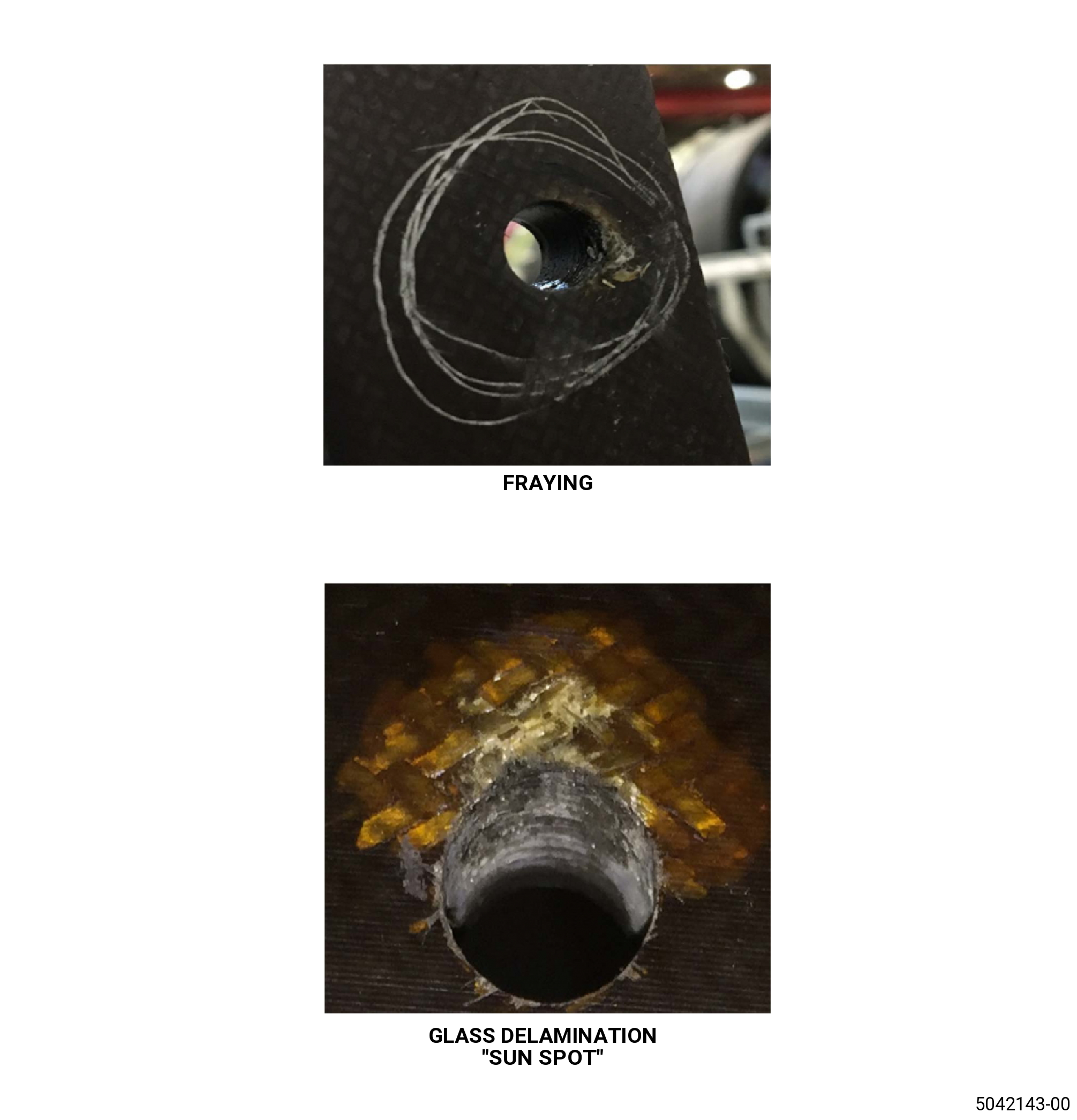
(1)Fraying at the bolthole edges:
Maximum serviceable limit:
Any amount, provided there are no glass plies missing, and no delamination or crack like defects are found in the bolthole inner surface.
Repair method:
Repair the fan case. Refer to TASK 72-21-01-300-802 (72-21-01, REPAIR 003).
Subtask 72-21-01-220-022
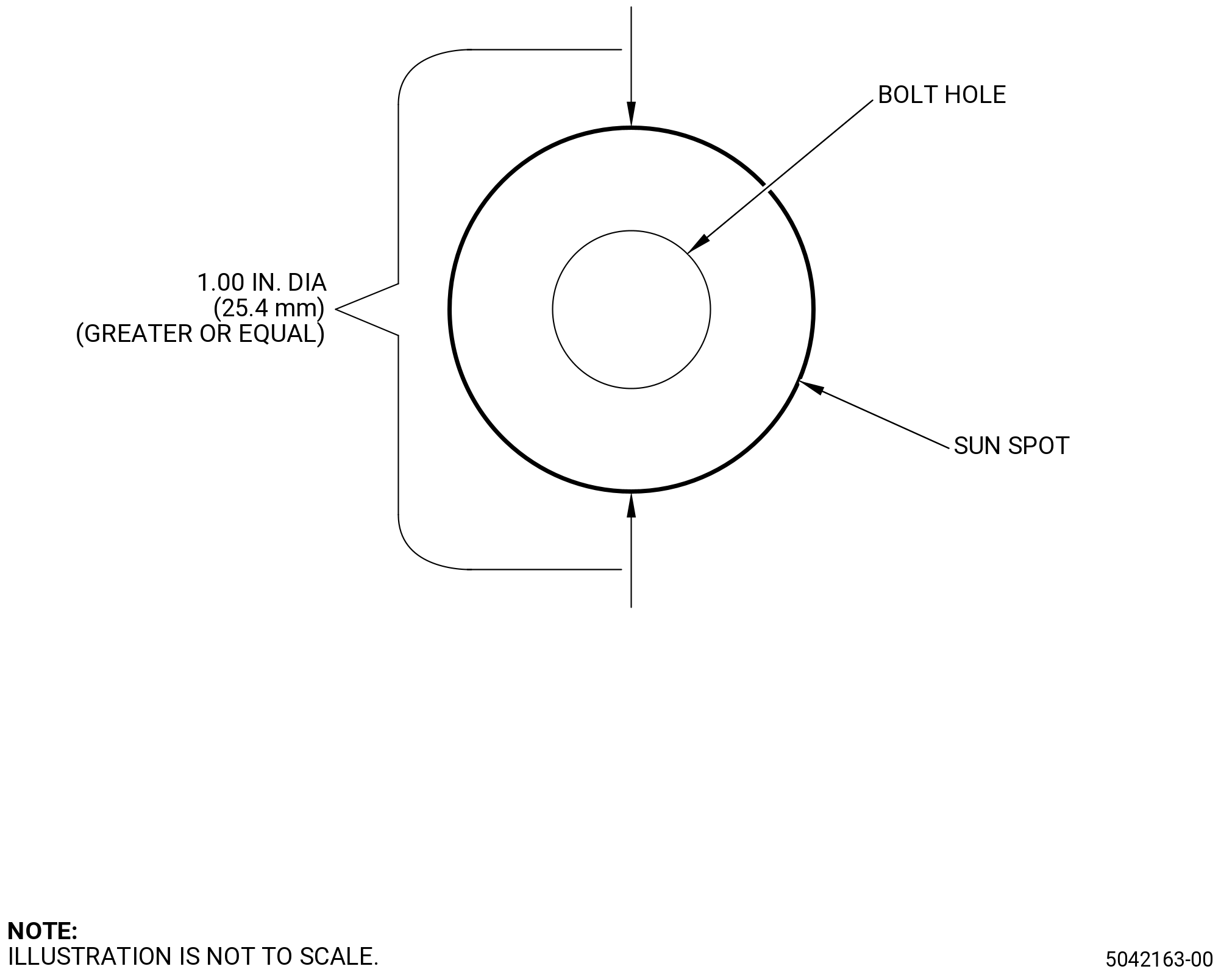
(2)Bolthole edge ply damage “sun spot”:
Maximum serviceable limit:
Any amount, 0.100 inch (2.54 mm) in depth, 1.00 inch (25.4 mm) in diameter, if there are no missing glass plies or no delamination or crack on the inner surface of boltholes.
Repair method:
Repair the fan case. Refer to TASK 72-21-01-300-802 (72-21-01, REPAIR 003).
NOTE:
Bolt hole edge ply damage can result in discoloration in the resin material of the laminates (sunspots).
Subtask 72-21-01-220-023
(3)Missing glass plies or tear outs:
Maximum serviceable limit:
0.020 inch (0.50 mm) in depth and 0.5 inch (12.7 mm) in diameter, if carbon plies are not exposed.
NOTE:
Glass plies will be in yellowish shade while carbon plies will be in black shade.
Repair method:
Repair the fan case. Refer to TASK 72-21-01-300-802 (72-21-01, REPAIR 003).
Subtask 72-21-01-220-024
(4)Cracks on the outer diameter surface:
Maximum serviceable limit:
Cracks through the plies are not permitted.
Repair method:
Replace the forward fan case.
Subtask 72-21-01-220-062
(5)Crazing in resin rich areas:
Maximum serviceable limit:
Any amount.
Repair method:
Not applicable.
Subtask 72-21-01-220-025
(6)Delaminations in the flanges:
Maximum serviceable limit:
0.016 inch (0.41 mm) in depth at the forward flange “A” and aft flange “B”.
Repair method:
Repair. Refer to TASK 72-21-01-300-803 (72-21-01, REPAIR 003).
Subtask 72-21-01-220-026
(7)Nicks, dents, scratches, rubs, and scuffs on flanges except the OD surface of flanges:
Maximum serviceable limit:
0.016 inch (0.41 mm) in depth at the forward flange “A” and aft flange “B”. Open indications with visible fiber damage are not serviceable.
Repair method:
Repair the fan case. Refer to TASK 72-21-01-300-802 (72-21-01, REPAIR 003) .
Subtask 72-21-01-220-067
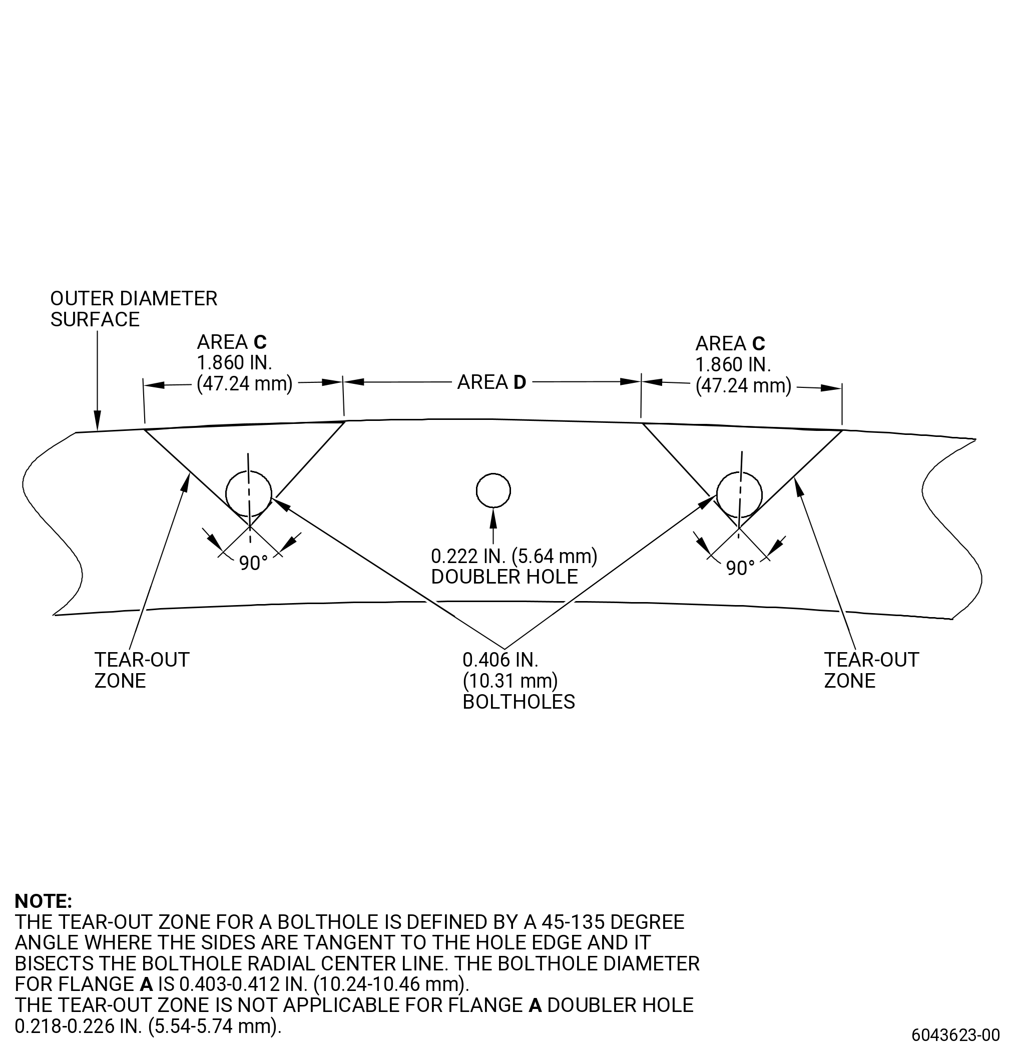
(8)Nicks, dents, scratches, rubs, scuffs, and fretting on the OD surface of flanges in area C (tear out zone). Refer to Figure 803 (Sheet 3) and Figure 803 (Sheet 4):
Maximum serviceable limit:
Not serviceable.
Repair method:
Contact GE Engineering.
Subtask 72-21-01-220-068
(9)Nicks, dents, scratches, rubs, scuffs, and fretting on the OD surface of flanges in area D (outside of tear out zone). Refer to Figure 803 (Sheet 3) and Figure 803 (Sheet 4):
Maximum serviceable limit:
0.05 inch (12.7 mm) in depth at flanges "A" and "B". Open indications with visible fiber damage are not serviceable.
Repair method:
Repair the fan case. Refer to TASK 72-21-01-300-802 (72-21-01, REPAIR 003) .
Subtask 72-21-01-220-053
(10)Pitting:
NOTE:
Surface condition in which pin holes or pits are evident in the surface resin only, but no fibers are visible or exposed.
Maximum serviceable limit:
Any amount, up to 0.010 inch (0.25 mm) in diameter and 0.010 inch (0.25 mm) in depth and the fibers are not exposed and broken.
Repair method:
Repair. Refer to TASK 72-21-01-300-802 (72-21-01, REPAIR 003) .
Subtask 72-21-01-220-069
(11)Missing epoxy resin:
NOTE:
Glass plies beneath the epoxy resin will be exposed when the epoxy resin is missing.
Maximum serviceable limit:
Any amount, if carbon fibers are not exposed.
Repair method:
Repair the fan case. Refer to TASK 72-21-01-300-802 (72-21-01, REPAIR 003) .
Subtask 72-21-01-220-027
C.Do an inspection of casing shell inner and outer diameter for:
(1)Nicks, dents, scratches, rubs, and scuffs:
Maximum serviceable limit:
Any amount, up to 0.125 inch (3.18 mm) in width and 0.016 inch (0.41 mm) in depth and no delamination.
Repair method:
Repair. Refer to TASK 72-21-01-300-802 (72-21-01, REPAIR 003).
Subtask 72-21-01-220-028
(2)Damage to the carbon fibers (below the protective plies, 0.016 inch (0.41 mm):
Maximum serviceable limit:
Not serviceable.
Repair method:
Replace the forward fan case.
Subtask 72-21-01-220-054
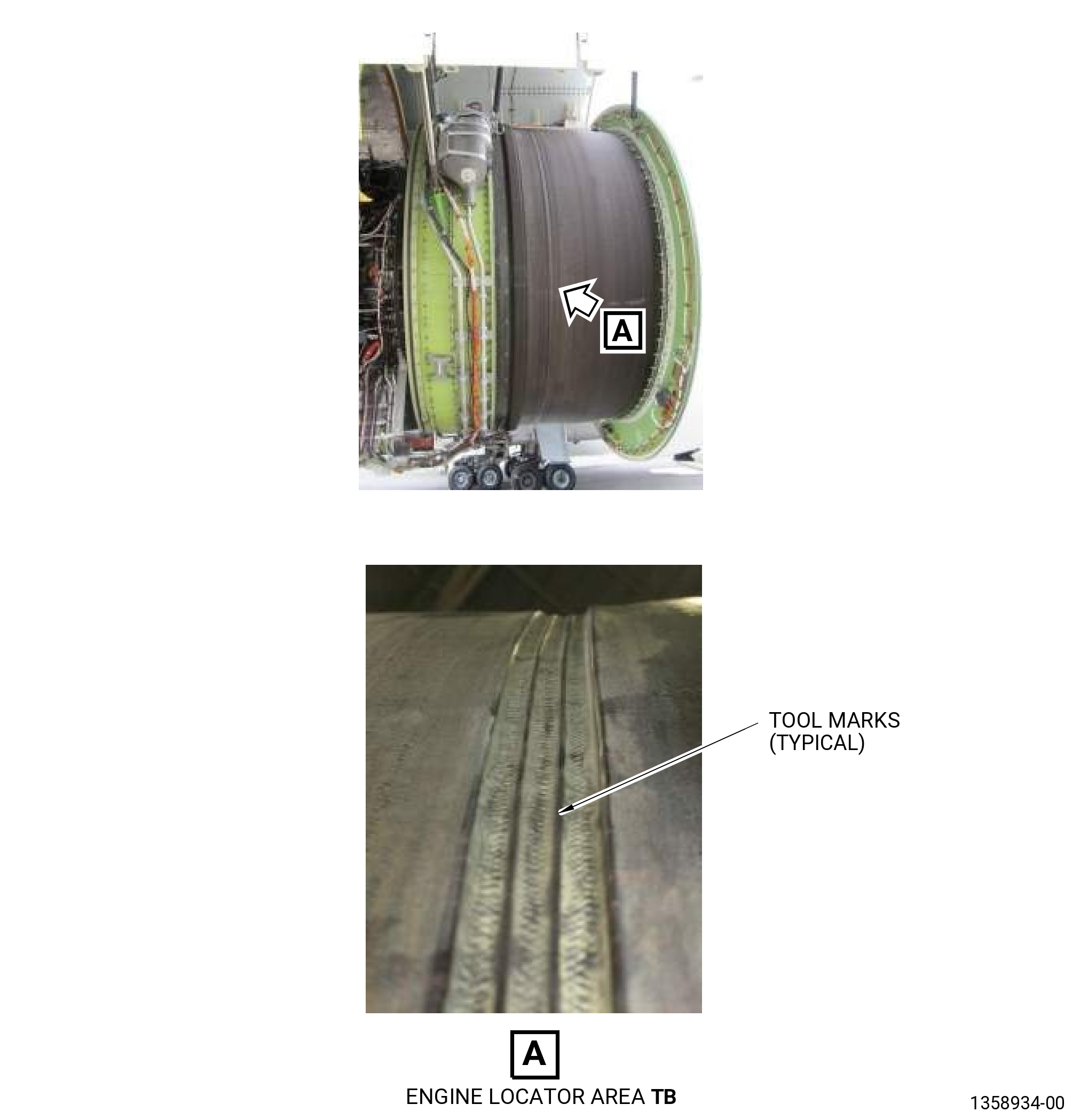
(3)Axial and circumferential shiny tool marks/steps near the forward flange:
NOTE:
Axial steps are typically separated by 5.0 inches (127 mm) to 6.0 inches (152 mm) with some only separated by 2.0 inches (51 mm).
Maximum serviceable limit:
Any amount, any length permitted in 5.0 inches (127 mm) of the forward flange.
Subtask 72-21-01-220-065
(4)Circumferential 360 degree channel located 19.0 inches (483 mm) forward of the aft flange:
NOTE:
A local surface condition of severe but gradual contour change affecting both the fabric and the resin matrix.
Maximum serviceable limit:
Permitted up to 2.0 inches (51 mm) in width.
Repair method:
Not applicable.
Subtask 72-21-01-220-055
(5)In-plane wrinkles in the flanges and the casing shell:
Maximum serviceable limit:
Any amount.
Repair method:
Not applicable.
NOTE:
Defect definition: Fabric gathered in creases, furrows, ridges, or folds in which the distortion is within the surface or plane of the part contour.
Subtask 72-21-01-220-056
(6)Resin ridges in the casing shell:
Maximum serviceable limit:
Any amount.
Repair method:
Not applicable.
NOTE:
A raised surface condition consisting of resin formed in areas that do not contain fiber.
Subtask 72-21-01-220-057
(7)Outer case surface crazing:
Maximum serviceable limit:
Any amount.
Repair method:
Not applicable.
NOTE:
Crazing is minute cracks in the surface resin. Crazing can have no broken fibers.
Subtask 72-21-01-220-058
(8)Outer case surface cracks:
Maximum serviceable limit:
Not serviceable.
Repair method:
Replace the forward fan case.
NOTE:
Cracks can be identified by exposed fibers where the crack has resulted in a separation of protective plies.
Subtask 72-21-01-220-059
(9)Surface porosity:
NOTE:
Surface condition in which pin holes or pits are evident in the surface resin only, but no fibers are visible or exposed.
Maximum serviceable limit:
Any amount, if porosity does not extend below the first protective ply, 0.016 inch (0.41 mm) in depth and the fibers are not exposed and broken.
Repair method:
Replace the forward fan case.
Subtask 72-21-01-220-061
(10)Outer case variation in color:
Maximum serviceable limit:
Any amount in shades of grey, brown, or black.
Repair method:
Remove any loose material as follows:
WARNING:
ISOPROPYL ALCOHOL IS TOXIC AND FLAMMABLE. USE PERSONAL PROTECTION EQUIPMENT. USE IN A WELL-VENTILATED AREA.
(a)Remove any loose material with a C10-182  cleaning cloth and C04-035  isopropyl alcohol.
Subtask 72-21-01-220-070
(11)Missing epoxy resin:
NOTE:
Glass plies beneath the epoxy resin will be exposed when the epoxy resin is missing.
Maximum serviceable limit:
Any amount, if carbon fibers are not exposed.
Repair method:
Repair the fan case. Refer to TASK 72-21-01-300-802 (72-21-01, REPAIR 003) .
Subtask 72-21-01-220-029
D.Do an inspection of stiffening hats for:
(1)Nicks, dents, scratches, rubs, and scuffs:
Maximum serviceable limit:
Any amount up to 0.030 inch (0.76 mm) in depth and 3.00 inches (76.2 mm) in length. No delamination is permitted.
NOTE:
Use a steel rod 0.375 inch (9.5 mm) in diameter and 2.0 inches (51.0 mm) long with a round end to tap on the stiffening cap in the damage area while listening for clicking sounds. If a solid click sound is heard, the area does not have a delamination. If a hollow or dull sound is heard, the area has a delamination.
Repair method:
Repair. If no delamination is found, refer to TASK 72-21-01-300-801 (72-21-01, REPAIR 004) .
If a delamination is found, replace the forward fan case.
Subtask 72-21-01-220-030
(2)Disbonds between stiffening hats to casing shell:
Maximum serviceable limit:
Not serviceable.
Repair method:
Contact GE Engineering.
Subtask 72-21-01-220-071
(3)Missing epoxy resin:
NOTE:
Glass plies beneath the epoxy resin will be exposed when the epoxy resin is missing.
Maximum serviceable limit:
Any amount, if carbon fibers are not exposed.
Repair method:
Repair the fan case. Refer to TASK 72-21-01-300-801 (72-21-01, REPAIR 004).
Subtask 72-21-01-220-031
E.Do an inspection of stiffening caps for:
(1)Nicks, dents, scratches, rubs, and scuffs:
Maximum serviceable limit:
Any amount in depth. No delamination is permitted
NOTE:
Use a steel rod 0.375 inch (9.5 mm) in diameter and 2.0 inches (51.0 mm) long with a round end to tap on the stiffening cap in the damage area while listening for clicking sounds. If a solid click sound is heard, the area does not have a delamination. If a hollow or dull sound is heard, the area has a delamination.
Repair method:
Repair. If no delamination is found, refer to TASK 72-21-01-300-801 (72-21-01, REPAIR 004) .
If a delamination is found, replace the forward fan case.
Subtask 72-21-01-220-032
(2)Disbonds between stiffening caps to stiffening hats:
Maximum serviceable limit:
Not serviceable.
Repair method:
Replace the forward fan case.
Subtask 72-21-01-220-072
(3)Missing epoxy resin:
NOTE:
Glass plies beneath the epoxy resin will be exposed when the epoxy resin is missing.
Maximum serviceable limit:
Any amount, if carbon fibers are not exposed.
Repair method:
Repair the fan case. Refer to TASK 72-21-01-300-801 (72-21-01, REPAIR 004).
Subtask 72-21-01-220-010
F.Do an inspection of the captive nut assemblies for:
(1)Loose or missing rivets:
Maximum serviceable limit:
Not serviceable.
Maximum repairable limit:
Any amount.
Repair method:
Replace the rivets. Use wet installation. Refer to TASK 70-13-00-390-001 (RIVETED JOINTS) .
Subtask 72-21-01-220-011
(2)Loss of the locking feature of the captive nuts:
Maximum serviceable limit:
Run-on torque must be more than 10 lb in. (1.1 N.m.).
Maximum repairable limit:
Any amount.
Repair method:
Replace the captive nut. Use wet installation. Refer to TASK 70-13-00-390-001 (RIVETED JOINTS) .
Subtask 72-21-01-220-012
(3)Damaged captive nut cage:
Maximum serviceable limit:
Not serviceable.
Maximum repairable limit:
Any amount.
Repair method:
Replace the captive nut assembly. Use wet installation to replace the rivets. Refer to TASK 70-13-00-390-001 (RIVETED JOINTS) .
Subtask 72-21-01-220-013
G.Do an inspection of the abradable shroud for:
(1)Voids, wear grooves, rubs, and areas not bonded to the facesheet:
Maximum serviceable limit:
Any amount, 0.08 inch (2.0 mm) in depth, if:
The largest area of damage is not more than 6.0 sq in. (39 sq cm).
The total damage is not more than 40.0 sq in. (258 sq cm).
There is a minimum distance of the maximum dimension of adjacent voids between the damaged areas.
Repair method:
Repair the abradable shroud. Refer to TASK 72-00-01-300-803 (72-00-01, REPAIR 002) or TASK 72-00-01-300-801 (72-00-01, REPAIR 003) .
Subtask 72-21-01-220-014
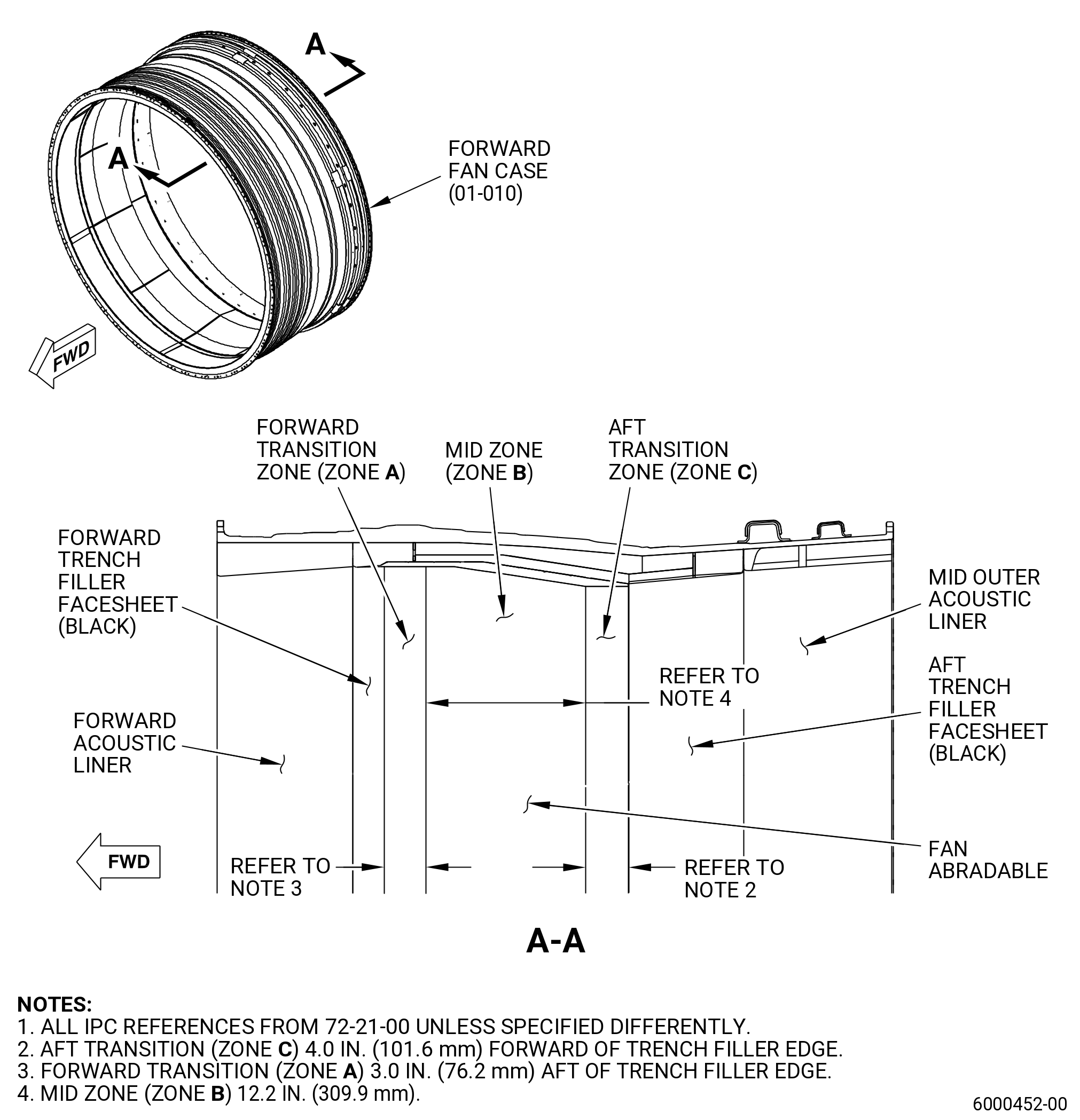
(2)Spalled, loose, or missing abradable material in the transition zones. Refer to Figure 804.
Maximum serviceable limit:
Zone A: Any number less than 2.0 in. (50.8 mm) in diameter and 0.225 in. (5.72 mm) in depth, and no more than 100 sq in. (64516 sq mm)
Zone B: Any number less than 2.0 in. (50.8 mm) in diameter and 0.225 in. (5.72 mm) in depth, and no more than 130 sq in. (83870.8 sq mm)
Zone C: Any amount permitted.
Repair method:
Repair. Refer to TASK 72-00-01-300-803 (72-00-01, REPAIR 002) or TASK 72-00-01-300-801 (72-00-01, REPAIR 003) .
Subtask 72-21-01-220-038
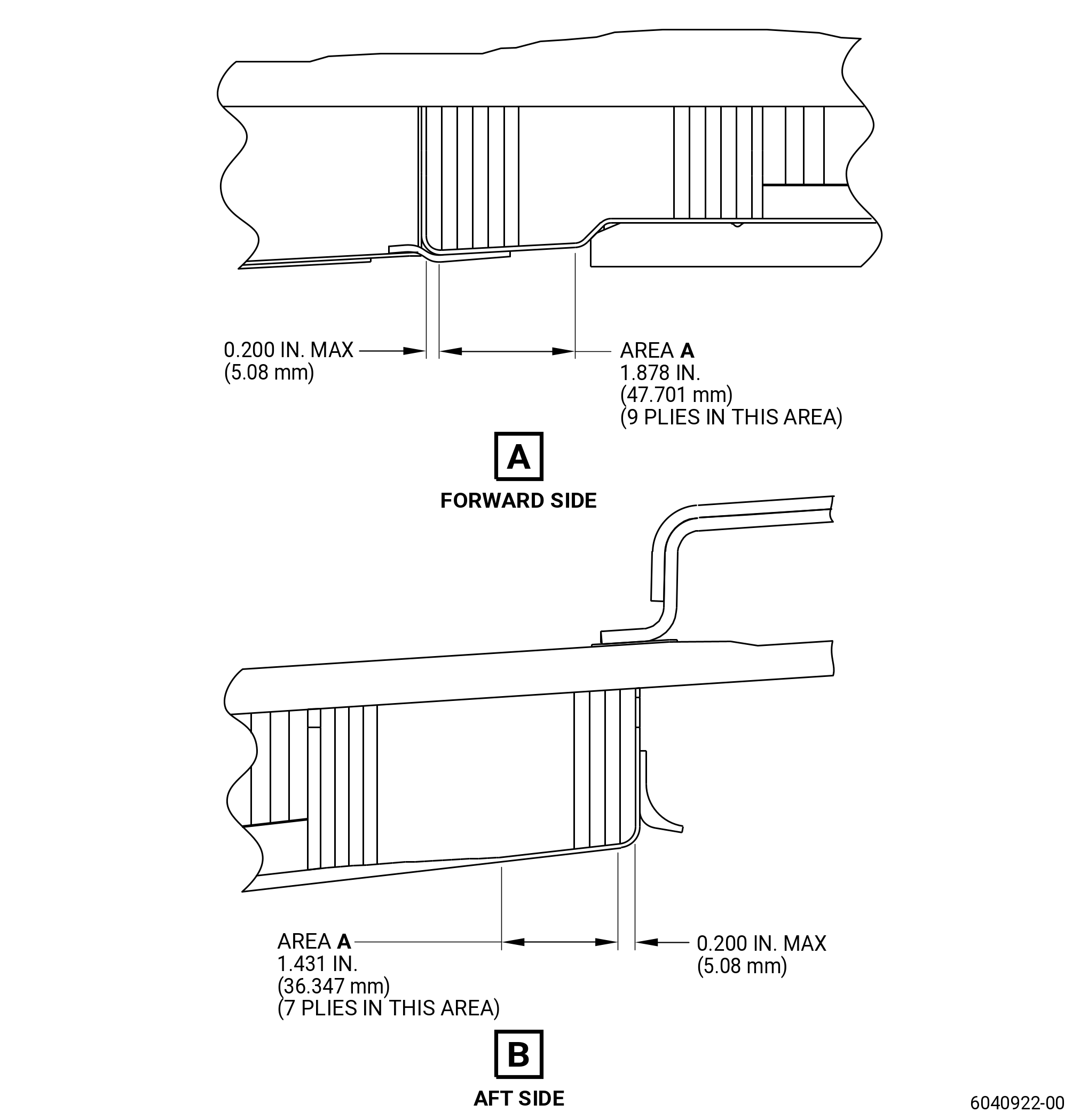
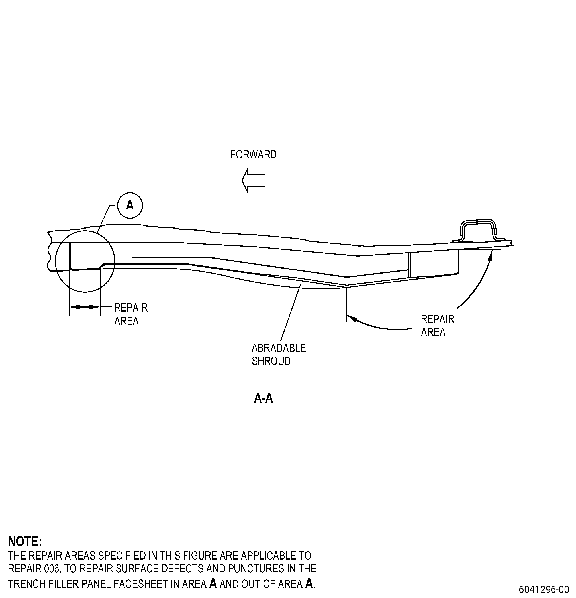
(3)Surface defects and punctures in the trenchfiller facesheet of area A. Refer to Figure 802, Figure 808, and Figure 809:
Maximum serviceable limit:
0.03 inch (0.76 mm) in depth and 0.50 inch (12.7 mm) in diameter, if there is no delamination, disbond or visible exposed fibers.
Repair method:
Repair. Refer to TASK 72-00-01-300-806 (72-00-01, REPAIR 008) or TASK 72-21-01-300-804 (72-21-01, REPAIR 006) .
Subtask 72-21-01-220-073
(4)Surface defects and punctures in the trench filler facesheet outside of area A. Refer to Figure 802, Figure 808, and Figure 809:
Maximum serviceable limit:
0.03 inch (0.76 mm) in depth and 0.50 inch (12.7 mm) in diameter, if there is no delamination or disbond or visible exposed fibers.
Repair method:
Repair. Refer to TASK 72-00-01-300-801 (72-00-01, REPAIR 003) or TASK 72-21-01-300-804 (72-21-01, REPAIR 006).
* * * FOR ALL
Figure 802   (Sheet 1 ) Fan Stator Module Assembly - Facesheet Repair Area
* * * FOR ALL
Figure 802   (Sheet 1 ) Fan Stator Module Assembly - Facesheet Repair Area
Subtask 72-21-01-220-033
H.Do an inspection of the eight trench filler panel joints and eight abradable panel joints for:
(1)Separations and cracks:
Maximum serviceable limit:
Any amount.
Repair method:
Not applicable.
Subtask 72-21-01-220-034
I.Do an inspection of the forward acoustic treatment for:
(1)Cracks:
Maximum serviceable limit:
Any amount, 6.0 inches (152 mm) in length and 0.060 inch (1.52 mm) in width, if:
No crack in the face sheet material is nearer than 10.0 inches (254 mm) to an adjacent area with a cracked face sheet material
Disbonds to the honeycomb core and delaminations within the face sheet are not permitted.
Repair method:
Repair. Refer to TASK 72-21-01-300-803 (72-21-01, REPAIR 001) .
Subtask 72-21-01-220-035
(2)Nicks and scratches on the facesheet:
Maximum serviceable limit:
Any amount, if the facesheet is not cracked.
Repair method:
Repair. Refer to TASK 72-21-01-300-803 (72-21-01, REPAIR 001) .
Subtask 72-21-01-220-036
(3)Tears and cuts on the facesheet:
Maximum serviceable limit:
Not serviceable.
Repair method:
Repair. Refer to TASK 72-21-01-300-803 (72-21-01, REPAIR 001) .
Subtask 72-21-01-220-037
(4)Delaminations on the facesheet:
Maximum serviceable limit:
Not serviceable.
Repair method:
Repair. Refer to TASK 72-21-01-300-803 (72-21-01, REPAIR 001) .
Subtask 72-21-01-220-052
(5)Punctures and holes on the facesheet:
Maximum serviceable limit:
Not serviceable.
Repair method:
Repair. Refer to TASK 72-21-01-300-803 (72-21-01, REPAIR 001) .
Subtask 72-21-01-220-074
(6)Missing closeout plies:
Maximum serviceable limit:
Any amount, along the circumference if the width of closeout plies in axial direction is 0.200 inch (5.08 mm) or more. Refer to Figure 810.
Repair method:
Repair. Refer to TASK 72-21-01-300-805 (72-21-01, REPAIR 007) .
Subtask 72-21-01-220-075
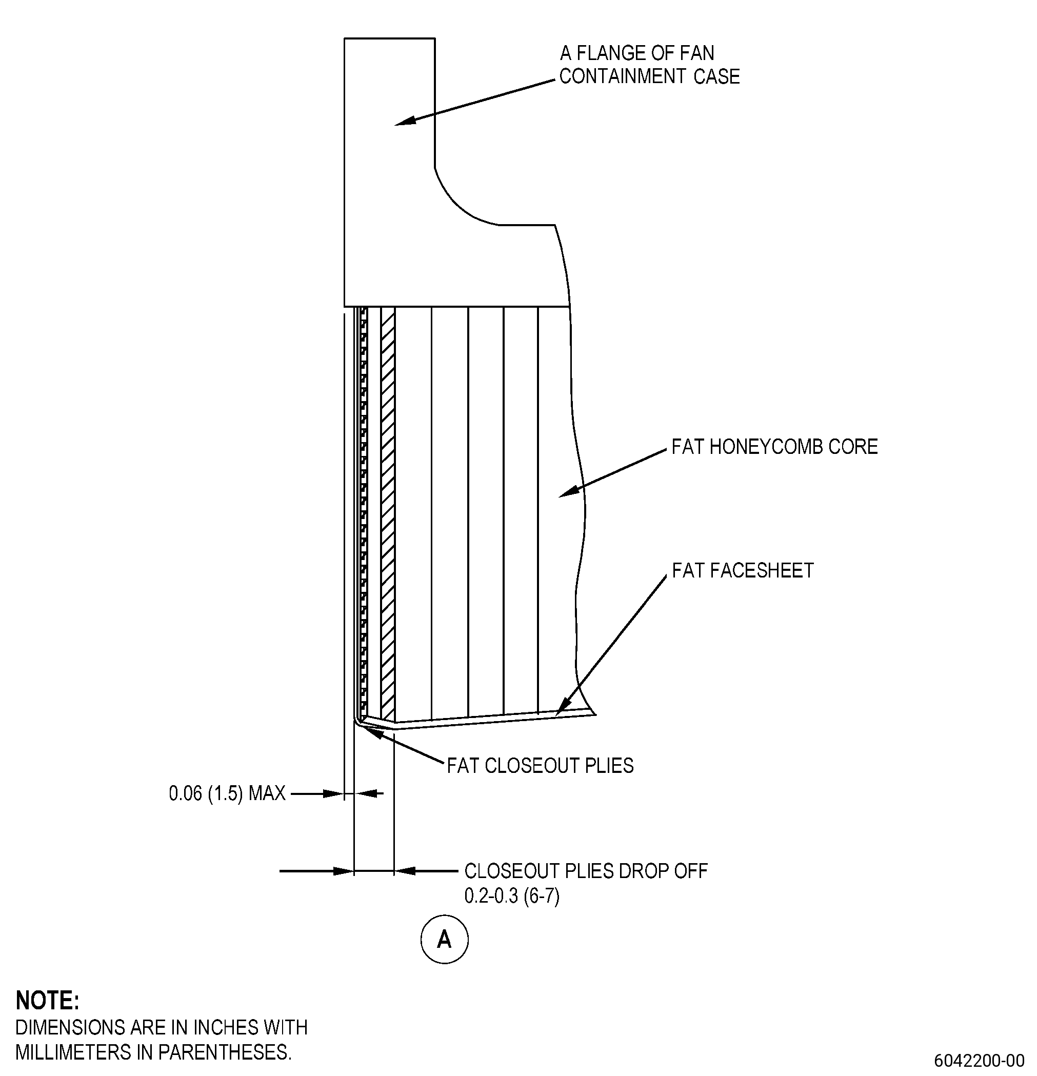
(7)Missing adhesive at the joint of the forward face with flange "A" and forward wall of the forward acoustic treatment. Refer to Figure 807.
Maximum serviceable limit:
Any amount, if there is no delamination or disbond.
Repair method:
Repair the fan case. Refer to TASK 72-21-01-300-802 (72-21-01, REPAIR 003) .
Subtask 72-21-01-220-086
(8)Delaminations on the closeout plies:
Maximum serviceable limit:
Not serviceable.
Repair method:
Repair. Refer to TASK 72-21-01-300-805 (72-21-01, REPAIR 007) .
Subtask 72-21-01-220-087
(9)Cracks on the closeout plies:
Maximum serviceable limit:
Not serviceable.
Repair method:
Repair. Refer to TASK 72-21-01-300-805 (72-21-01, REPAIR 007) .
* * * FOR ALL
* * * PRE SB   72-0039( Heavier Forward Fan Case )
Figure 803   (Sheet 1 ) Tool Marks on Outer Diameter of the Forward Containment Case
* * * FOR ALL
* * * SB   72-0039( Lighter Forward Fan Case )
Figure 803   (Sheet 2 ) Tool Marks on Outer Diameter of the Forward Containment Case
* * * FOR ALL
Figure 803   (Sheet 3 ) Forward Containment Case “A” Flange - Tear-Out Zone Definition
* * * FOR ALL
Figure 803   (Sheet 4 ) Forward Containment Case “B” Flange - Tear-Out Zone Definition
* * * FOR ALL
Figure 803   (Sheet 3 ) Tool Marks on Outer Diameter of the Forward Containment Case
* * * FOR ALL
Figure 803   (Sheet 6 ) Features on Outer Diameter of the Forward Containment Case
* * * FOR ALL
Figure 803   (Sheet 7 ) Indications at Forward and Aft Flange Boltholes
* * * FOR ALL
Figure 803   (Sheet 8 ) Indications at Forward and Aft Flange Boltholes
* * * FOR ALL
Figure 804   Abradable Zone Location
* * * FOR ALL
Figure 805   Missing Epoxy Resin on Flange Faces, Flange Edge and Casing Shell
* * * FOR ALL
Figure 806   Crazing on Resin Rich Areas at Corner of Flanges with Inner Diameter
* * * FOR ALL
Figure 807   Missing Adhesive at the Joint of Forward Face of Forward Acoustic Treatment with “A” Flange of Fan Containment Case
* * * FOR ALL
Figure 808   (Sheet 1 ) Trenchfiller Panel Facesheet - Repair Areas
* * * FOR ALL
Figure 808   (Sheet 2 ) Trenchfiller Panel Facesheet - Repair Areas
* * * FOR ALL
Figure 809   Trenchfiller Panel Facesheet - Typical Defects
* * * FOR ALL
Figure 810   (Sheet 1 ) Forward Containment Case - Forward Acoustic Treatment Closeout Plies
* * * FOR ALL
Figure 810   (Sheet 2 ) Forward Containment Case - Forward Acoustic Treatment Closeout Plies