| GENX-1B CLEANING,INSPECTION,AND REPAIR MANUAL | Dated: 07/27/2023 | |
| CIR 72-00-01 , REPAIR 002 | ||
| FAN STATOR MODULE ASSEMBLY - REPAIR - UNLIMITED SIZE ABRADABLE SHROUD REPAIR | ||
| GENX-1B CLEANING,INSPECTION,AND REPAIR MANUAL | Dated: 07/27/2023 | |
| CIR 72-00-01 , REPAIR 002 | ||
| FAN STATOR MODULE ASSEMBLY - REPAIR - UNLIMITED SIZE ABRADABLE SHROUD REPAIR | ||
| * * * FOR 1B/P/G03.1B/P/G04.1B/P1/G01 |
| TASK 72-00-01-300-803 |
| 1 . | Unlimited Size Abradable Shroud Repair. |
| CAUTION: |
|
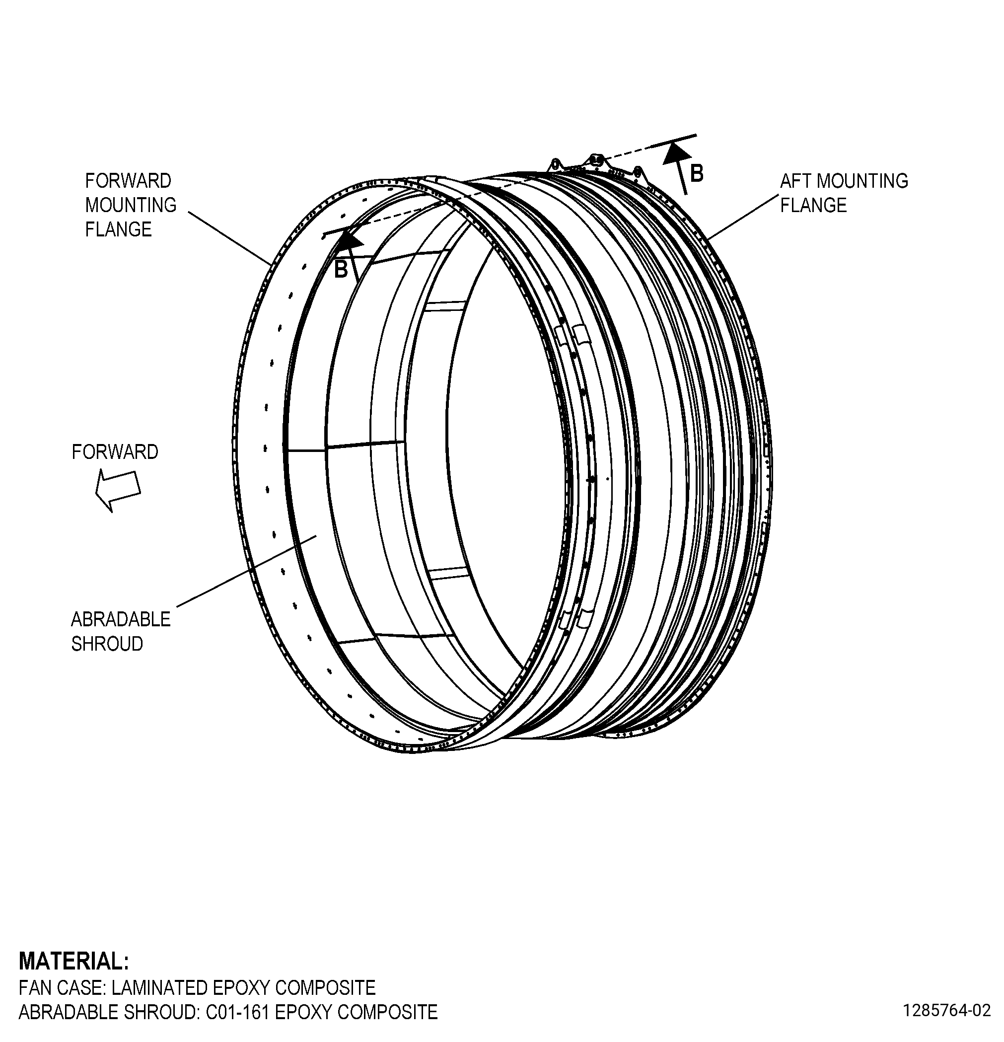
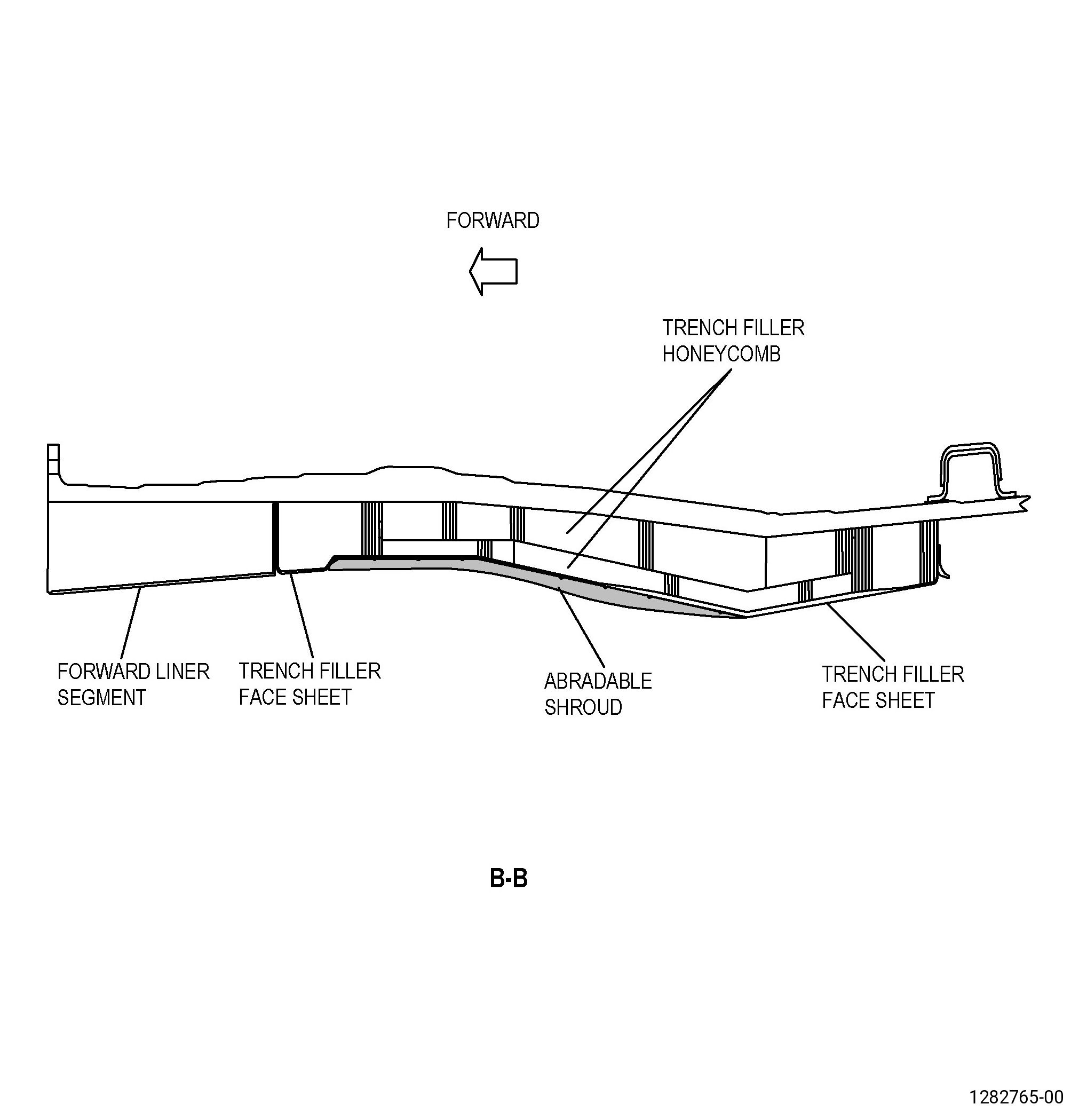
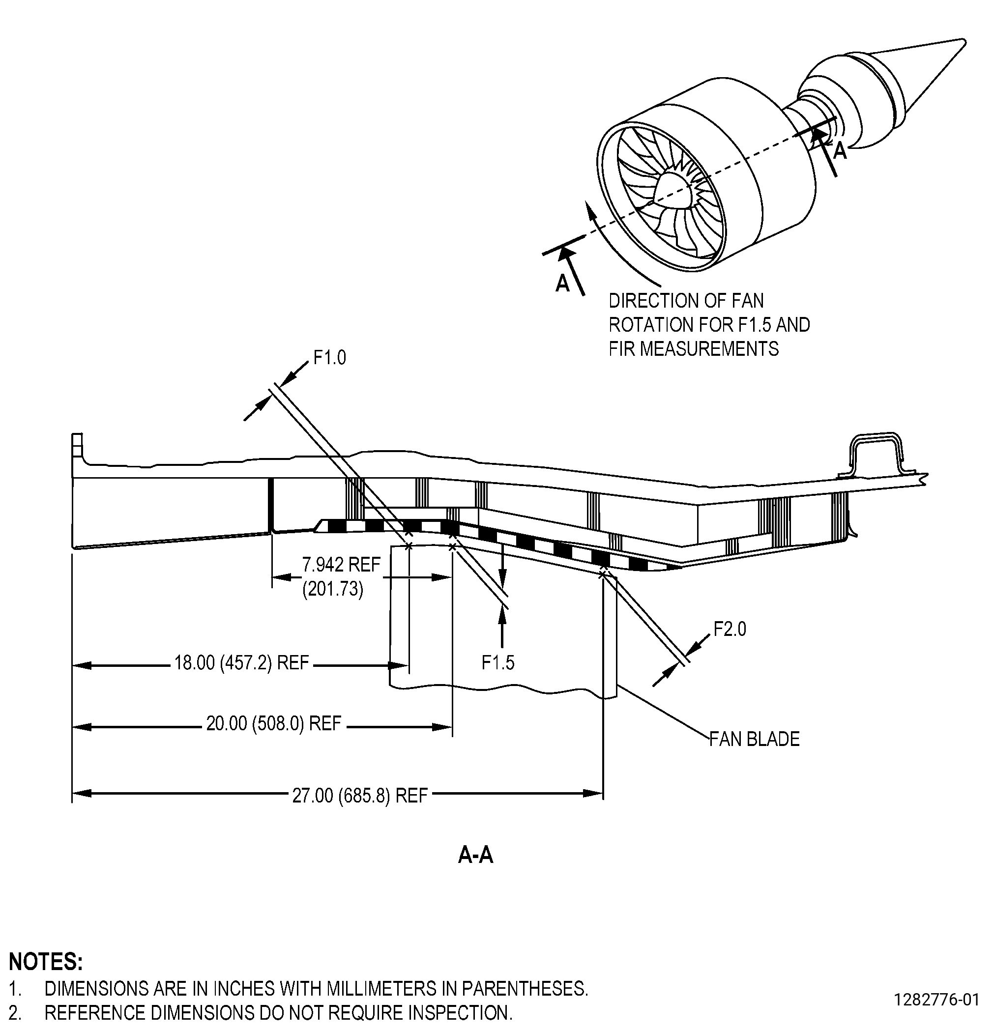
| A. | This procedure gives instructions to repair the fan stator module assembly forward fan case (fan case) abradable shroud (abradable shroud) by replacing the abradable material and restoring the contour with a grind tool. Refer to Figure 901. |
| B. | Deleted. |
| NOTE: |
|
| NOTE: |
|
| (4) | Deleted. |
| (a) | Deleted. |
| 4 | Deleted. |
| Maximum repairable limit: |
|
| 5 | Deleted. |
| Maximum repairable limit: |
|
| 6 | Deleted. |
| Maximum repairable limit: |
|
| C. | The subsequent table gives a list of the part numbers that are applicable to this repair. All part numbers are applicable to all paragraphs unless specified differently. |
|
|||||||||||||||||||||||
| D. | Proprietary/Complex Process Statement. |
| (1) | None. |
| 2 . | Tools, Equipment, and Materials. |
| NOTE: |
|
| A. | Tools and Equipment. |
| (1) | Special Tools |
| (2) | Standard Tools and Equipment. |
|
| (3) | Locally Manufactured Tools. |
|
| WARNING: |
|
| B. | Consumable Materials. |
|
| C. | Referenced Procedures |
|
| D. | Expendable Parts. None |
| E. | SPD Information. |
| (1) | Locally Manufactured SPD. None. |
| F. | Special Solutions. None. |
| G. | Test Specimens. None. |
| 3 . | Dimensional Information. |
| Subtask 72-00-01-220-122 |
| A. | Refer to Figure 901 for specified dimensions and locations. |
| NOTE: |
|
| NOTE: |
|
| 4 . | Setup Information. |
| Subtask 72-00-01-350-061 |
| WARNING: |
|
| CAUTION: |
|
| NOTE: |
|
| A. | Set-up the fan case for grinding by installing the 11C3001 grind tool. Refer to Figure 907 and do as follows: |
| (1) | Put the 11C4514 protective mat in the bottom of the fan case from the front of the fan case to aft of the abradable shroud. |
| (2) | Attach the 11C3001 grind tool, to the fan rotor as follows: |
| NOTE: |
|
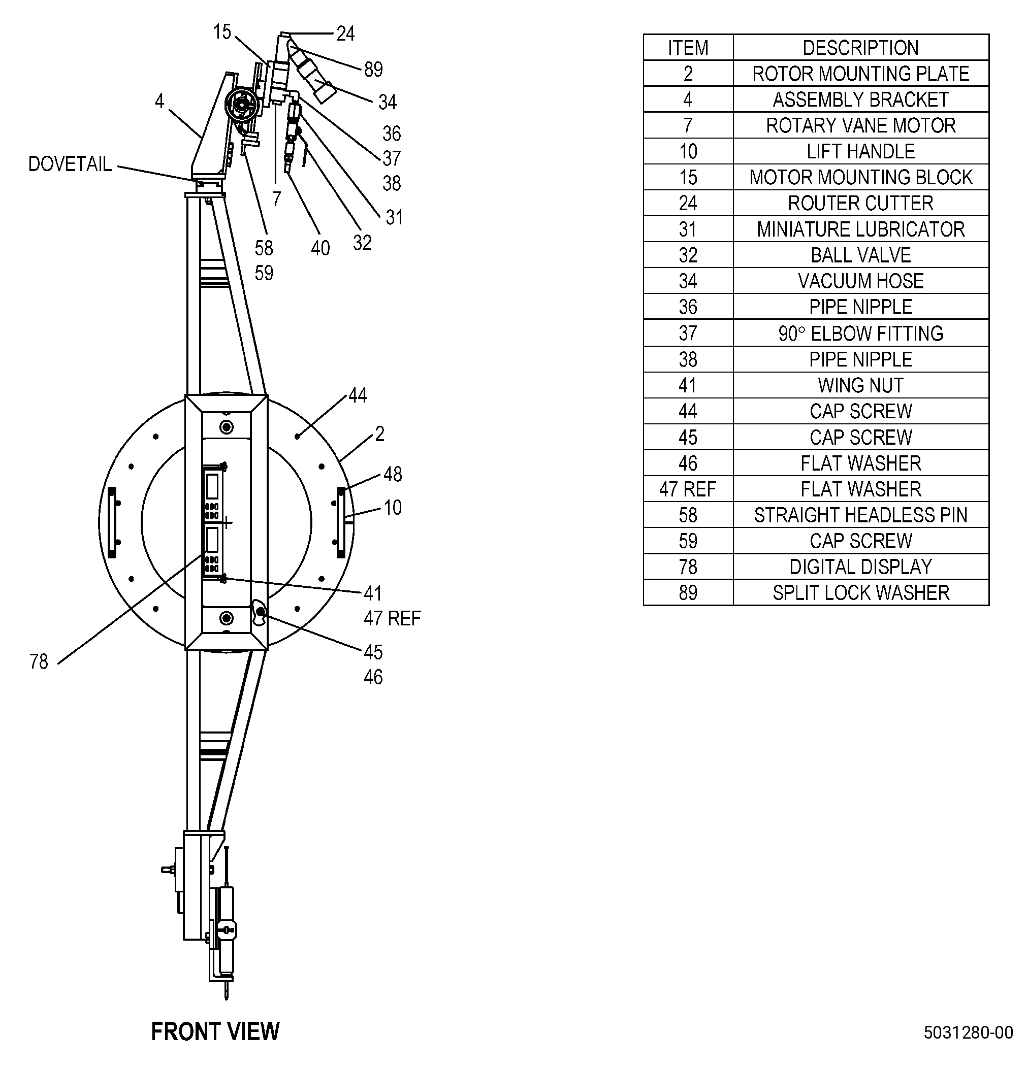
| (a) | Attach the rotor mounting plate (item 2) to the aft spinner support mounting holes on the fan rotor forward flange as follows: |
| 1 | Get 14 cap screws (item 44). |
| 2 | Get 13 slave barrel nuts (item 9) and one slave barrel nut (item 92). |
| NOTE: |
|
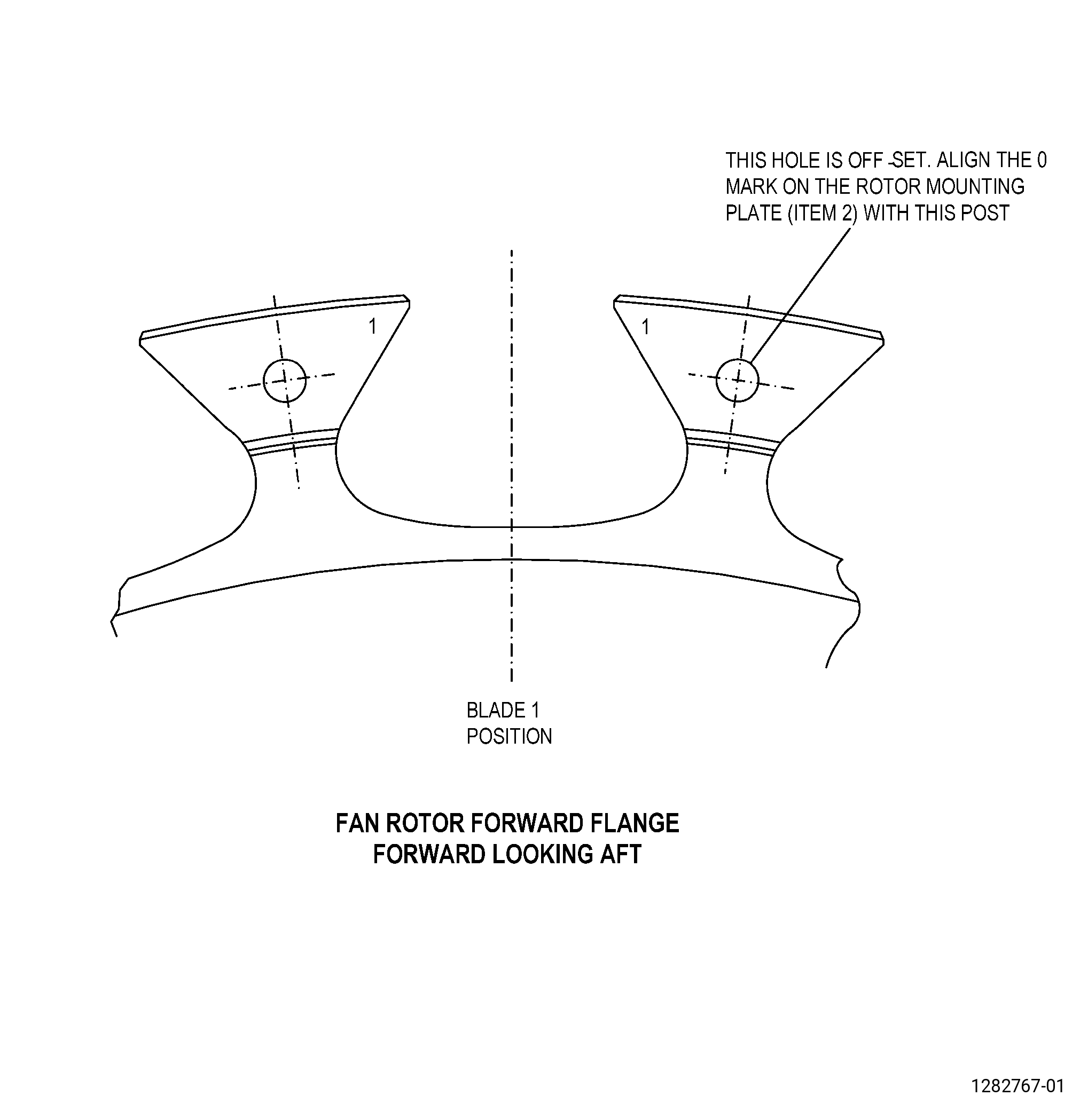
| 3 | Put the rotor mounting plate (item 2) on the location rabbet of the fan rotor forward flange, with the 0 mark at the post with the mark 1 which is clockwise (FLA) of the adjacent rotor post with the mark 1. Refer to Figure 903. |
| CAUTION: |
|
| 4 | Install the cap screws (item 44), the slave barrel nuts (item 9), and the slave barrel nut (item 92) as follows: |
| a | Install one cap screw (item 44) and the slave barrel nut (item 92) in the hole with the 0 mark with the flat of the slave barrel nut (item 92) facing aft. |
| b | Install the other 13 cap screws (item 44) in the remaining holes. |
| CAUTION: |
|
| c | Install each of the 13 slave barrel nuts (item 9) on one of the cap screws (item 44) in the remaining holes with the flat facing aft. |
| 5 | Tighten the 14 cap screws (item 44) in a criss-cross pattern to a torque of to 80 to 100 lb in. (9.1 to 11.2 Nm). |
| 6 | Make sure that the aft face of the rotor mounting plate (item 2) touches the fan rotor forward flange at each hole location as follows: |
| a | Get a shim of 0.0015 inch (0.038 mm) in thickness. |
| b | Try to put the shim between the aft face of the rotor mounting plate (item 2) and the fan rotor forward flange. |
| c | If the shim fits, loosen the cap screws (item 44) and do Subtask 72-00-01-350-061 (paragraph 4.A.(2)(a)5) again. |
| d | If the shim does not fit, the clearance is satisfactory and you can continue with this procedure. |
| (b) | Turn the rotor until the diamond pin on the rotor mounting plate (item 2) is at the 6:00 o’clock position. |
| (c) | Install the fixture frame (item 75) as follows: |
| WARNING: |
|
| 1 | If the cross slide assembly is attached to the fixture frame (item 75), remove it before you install the fixture frame (item 75). Refer to Figure 907 and as follows: |
| NOTE: |
|
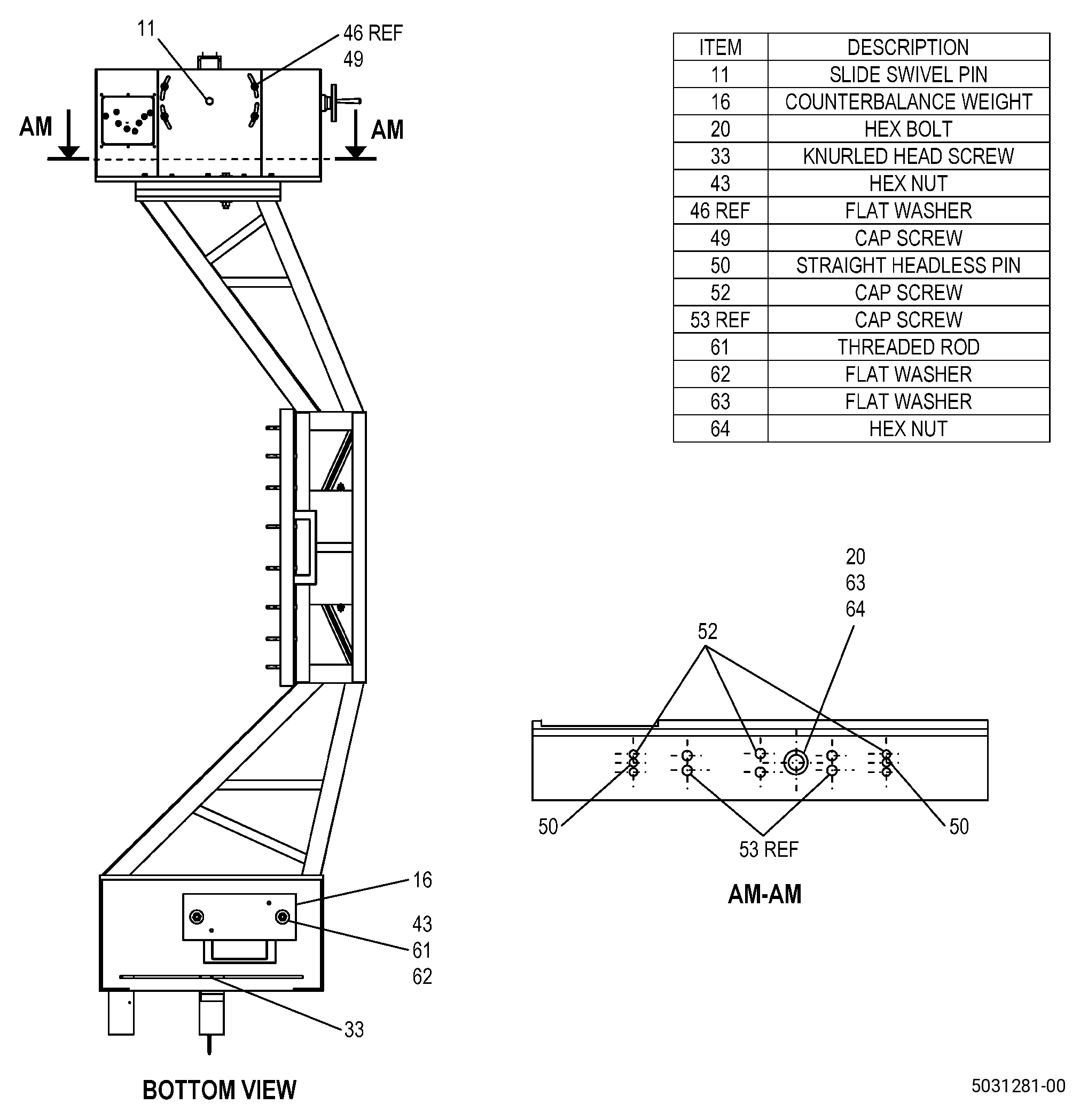
| a | If necessary, remove the hex bolt (item 20), the two flat washers (item 63), the hex nut (item 64), and the six cap screws (item 52) to remove the dovetail slide (item 17). |
| NOTE: |
|
| NOTE: |
|
| 2 | Get eight cap screws (item 45) and eight flat washers (item 46). |
| NOTE: |
|
| a | Deleted. |
| WARNING: |
|
| 3 | Lift the fixture frame (item 75) into place as follows: |
| a | Make sure that the fixture frame (item 75) is lifted by two or more persons. |
| b | Hold the fixture frame (item 75) vertically against the rotor mounting plate (item 2) with the indicator end down. |
| 4 | Push the pins on the rotor mounting plate (item 2) into the bushed holes on the fixture frame (item 75). |
| 5 | Attach the fixture frame (item 75) with the eight cap screws (item 45) and the eight flat washers (item 46). |
| 6 | Tighten the eight cap screws (item 45) to a torque of to 120 to 150 lb in. (13.6 to 16.9 Nm). |
| 7 | Make sure that the forward face of the rotor mounting plate (item 2) touches the fixture frame (item 75) at all hole locations as follows: |
| a | Get a shim of 0.0015 inch (0.038 mm) in thickness. |
| b | Try to put the shim between the fixture frame (item 75) and the forward face of the rotor mounting plate (item 2). |
| c | If the shim fits, loosen the cap screws (item 45) and do Subtask 72-00-01-350-061 (paragraph 4.A.(2)(c).5) to Subtask 72-00-01-350-061 (paragraph 4.A.(2)(c).7b) again. |
| d | If the shim does not fit, the clearance is satisfactory and you can continue with this procedure. |
| WARNING: |
|
| WARNING: |
|
| (d) | Attach the cross slide assembly as follows: |
| NOTE: |
|
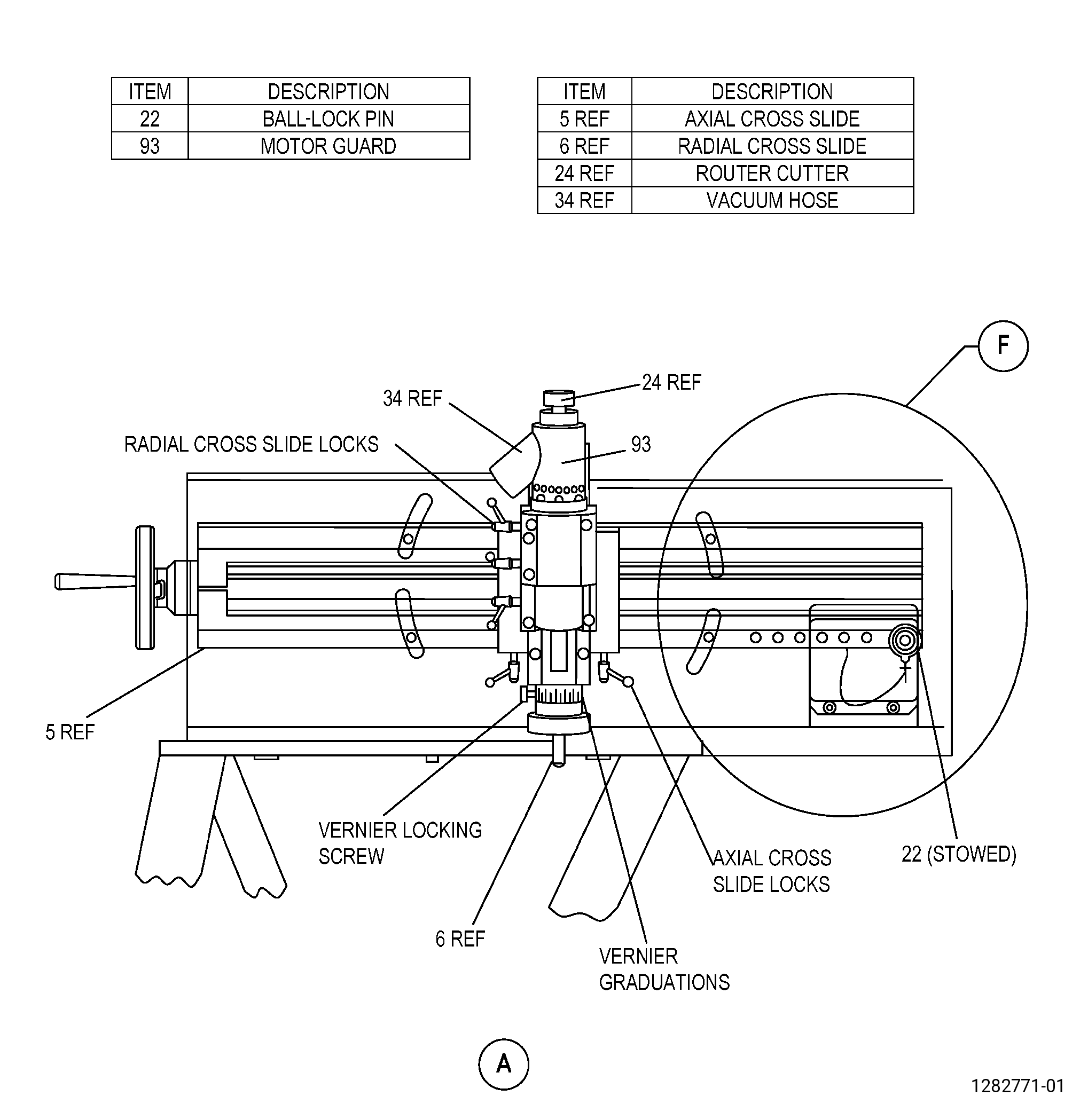
| 1 | Use the radial cross slide (item 6) to move the router cutter (item 24) approximately 0.100 inch (2.54 mm) away from the abradable shroud. |
| 2 | Get the hex bolt (item 20), the two flat washers (item 63), the hex nut (item 64), and the six cap screws (item 52). |
| 3 | Turn the fixture frame (item 75) until the end with the cross slide assembly is at the 6:00 o’clock position. |
| 4 | Push the cross slide assembly into the fixture frame (item 75) dovetail with the handle of the axial cross slide (item 5) in the forward position. |
| 5 | Align the 0.500 inch (12.70 mm) hole in the cross slide assembly with the fixture frame (item 75) dovetail. |
| 6 | Attach the cross slide assembly to the fixture (item 75) as follows: |
| CAUTION: |
|
| a | Install the hex bolt (item 20) and the related flat washers (item 63) and hex nut (item 64) in the 0.500 inch (12.70 mm) hole in the cross slide assembly and the fixture frame (item 75). |
| CAUTION: |
|
| b | Tighten the hex bolt (item 20) to a torque of to 120 to 150 lb in. (13.6 to 16.9 Nm). |
| c | Install the cap screws (item 52). |
| d | Tighten the cap screws (item 52) to a torque of to 80 to 100 lb in. (9.1 to 11.2 Nm). |
| WARNING: |
|
| CAUTION: |
|
| (e) | Attach the counterbalance weights (item 16) as follows: |
| 1 | Get the two counterbalance weights (item 16), two threaded rods (item 61), two hex nuts (item 43), and two flat washers (item 62). |
| 2 | Turn the fixture frame (item 75) on the fan rotor until the counterbalance weight attachment holes, on the opposite end of the frame from the cross slide assembly, are at the 6:00 o’clock position, and do as follows: |
| a | Hold the rotor tightly. |
| 3 | Put the threaded rods (item 61) in the counterbalance weight attachment holes with the bolthead on the right side (FLA). |
| 4 | Put the two counterbalance weights (item 16) on the threaded rods (item 61) and attach them with the two hex nuts (item 43) and the two flat washers (item 62). |
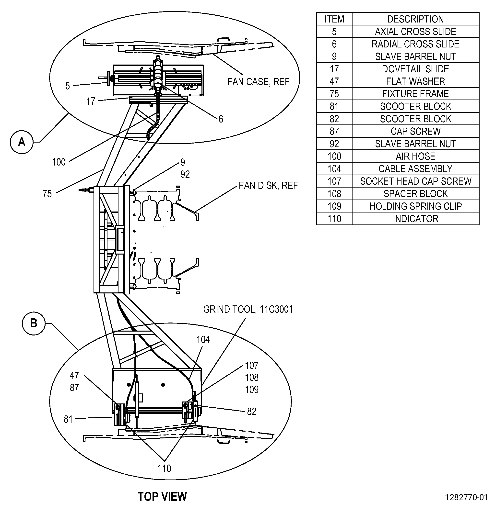
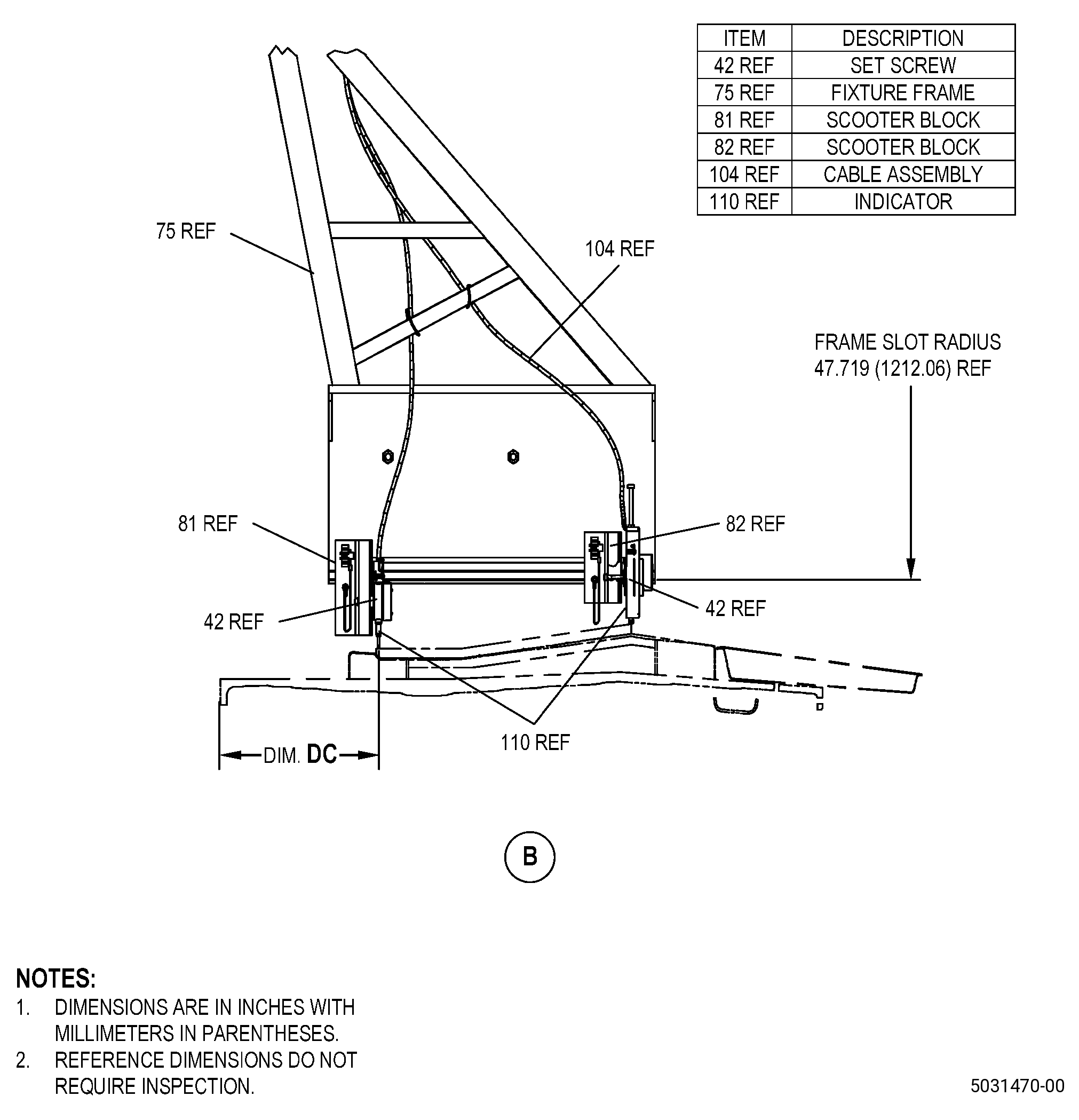
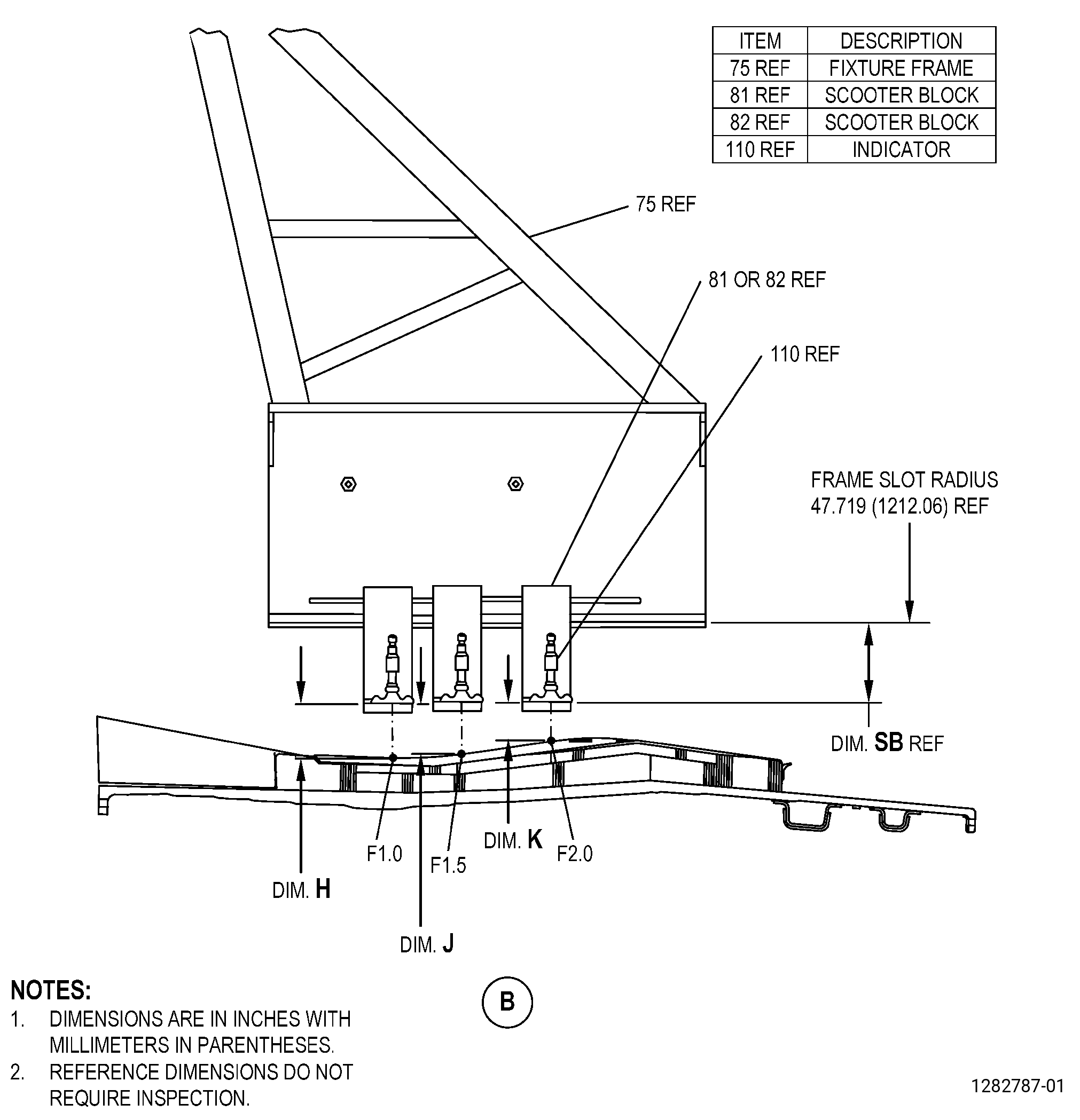
| (f) | If you do the runout measurements, attach the indicators (item 110) on the fixture frame (item 75) as follows: |
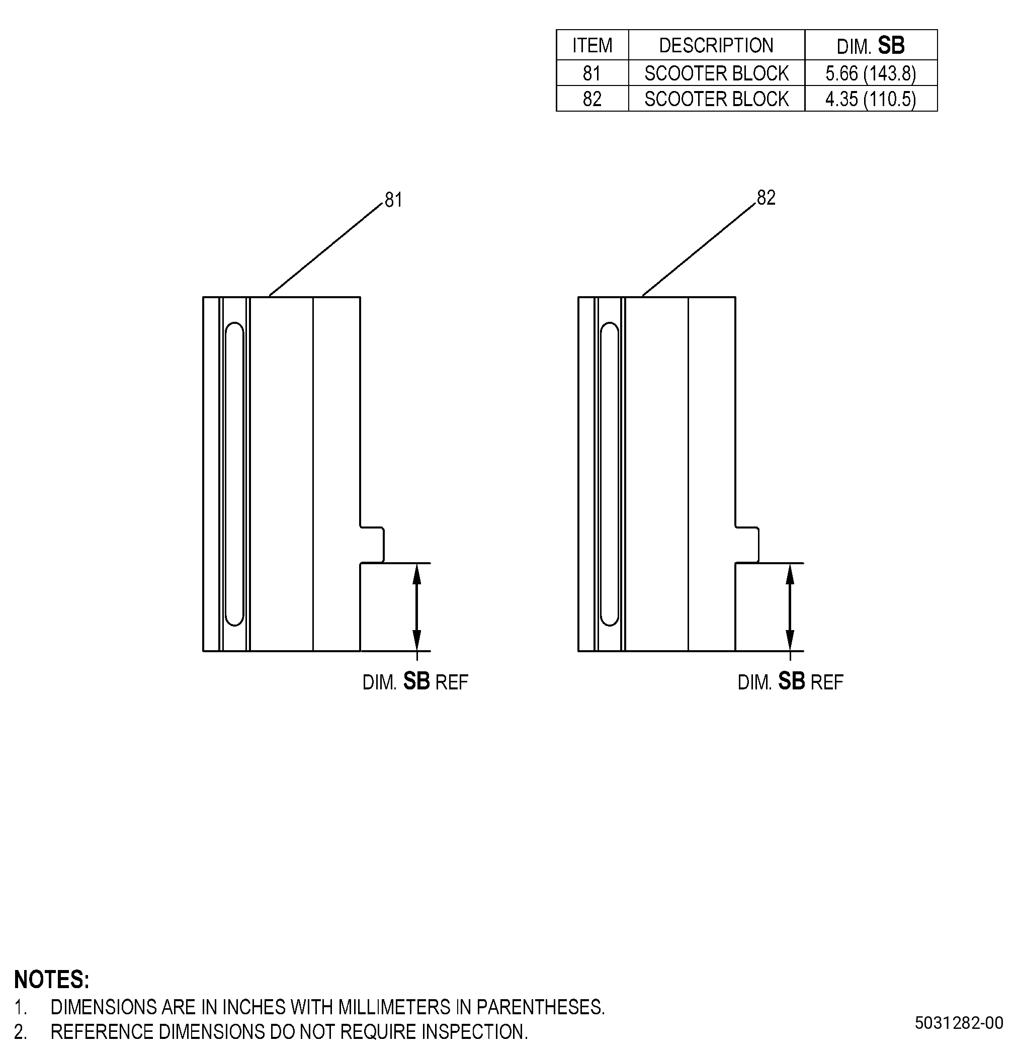
| 1 | Get the two scooter blocks (item 81 and item 82), the two indicators (item 110), the two set screws (item 42), two flat washers (item 47), the two cap screws (item 87), the two socket head cap screws (item 107), the two spacer blocks (item 108), the two holding spring clips (item 109), and the two knurled head screws (item 33). |
| NOTE: |
|
| 2 | Attach the scooter blocks (item 81 and item 82) to the frame slot as follows: |
| a | Use the two cap screws (item 87) to hold the scooter blocks (item 81 and item 82) in the correct axial position. |
| 3 | Attach the indicators (item 110) to the scooter blocks (item 81 and item 82) as follows: |
| a | Use the two socket head cap screws (item 107) to install the two spacer blocks (item 108) and the two holding spring clips (item 109) on the indicators (item 110). |
| b | Use the two set screws (item 42) to secure the lanyards on the indicators (item 110). |
| c | Use two flat washers (item 47) and the two knurled head screws (item 33) to attach the indicators (item 110) to the scooter blocks (item 81 and item 82). |
| 4 | Connect one of the cable assemblies (item 104) from the indicator (item 110) that you will use to the digital display (item 78). |
| 5 | Put the tip of the indicator (item 110) on the abradable shroud surface and set the digital display (item 78) to zero. |
| 6 | Make sure that the radially in movement of the indicator (item 110) reads negative on the digital display (item 78) and that the radially out movement reads positive. |
| 7 | If the digital display (item 78) shows negative for a radially out movement of the indicator (item 110) and positive for a radially in movement, refer to the manufacturer’s instructions to change the sign of the digital display (item 78). |
| 8 | Loosen the knurled head screws (item 33) to move the scooter blocks (item 81 and item 82) to the correct axial position that you will measure. |
| 9 | Tighten the knurled head screws (item 33) to keep the scooter blocks (item 81 and item 82) in the correct axial position that you will measure. |
| (g) | Deleted. |
| 1 | Deleted. |
| NOTE: |
|
| 2 | Deleted. |
| a | Deleted. |
| 3 | Deleted. |
| (3) | Attach the air hose (item 100) to the router assembly. |
| (4) | Attach the vacuum hose (item 34) to the vacuum exhaust port. |
| (5) | Remove the 11C4514 protective mat. |
| 5 . | Procedure. |
| Subtask 72-00-01-930-006 |
| A. | Make or buy the 11C3001 grind tool. Refer to Figure 907. |
| Subtask 72-00-01-930-007 |
| B. | Make or buy the locally manufactured tools that follow: |
| (1) | A profile template for repair areas with an axial dimension of 8.00 inches (203.2 mm) or more. Refer to Figure 902. |
| NOTE: |
|
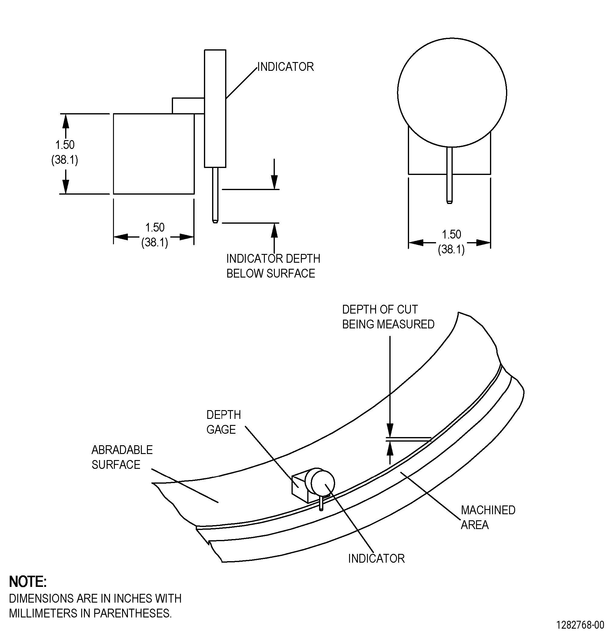
| (2) | A depth gauge. Refer to Figure 904. |
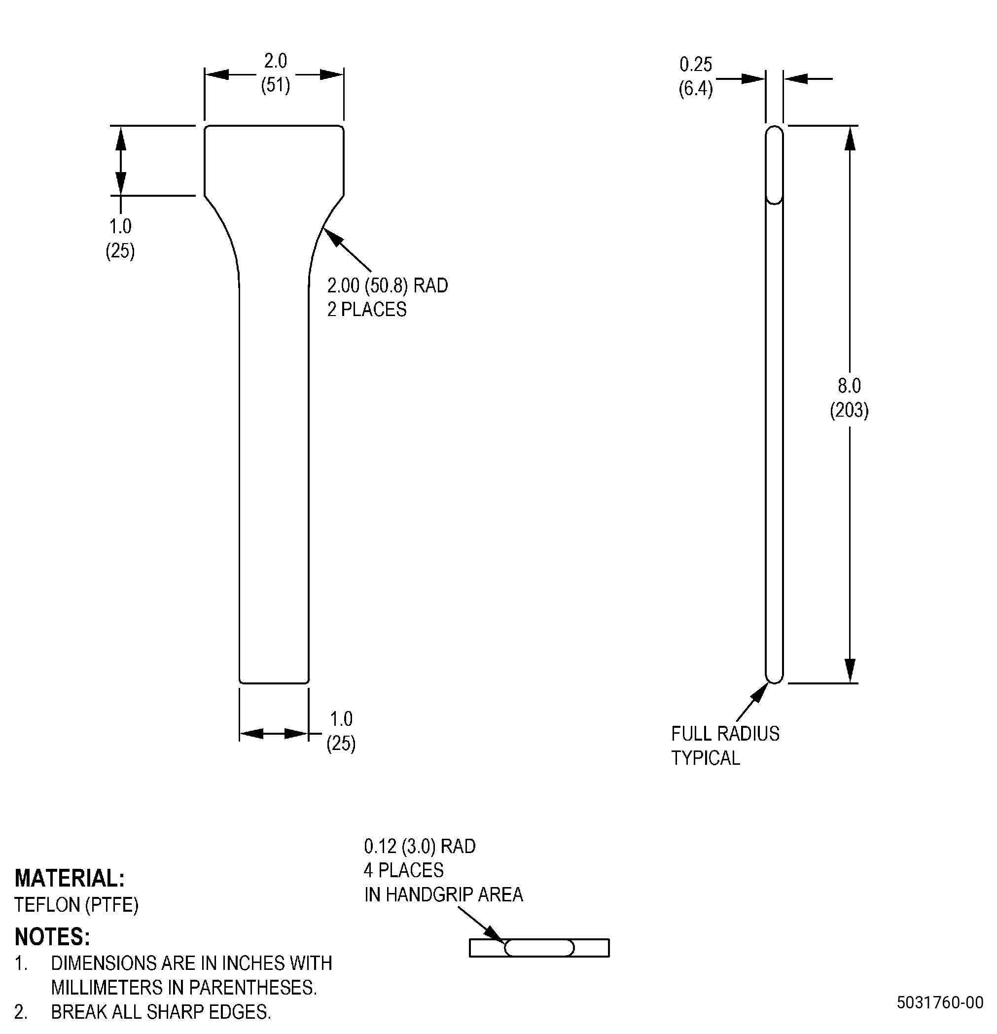
| (3) | A Teflon spatula. Refer to Figure 905. |
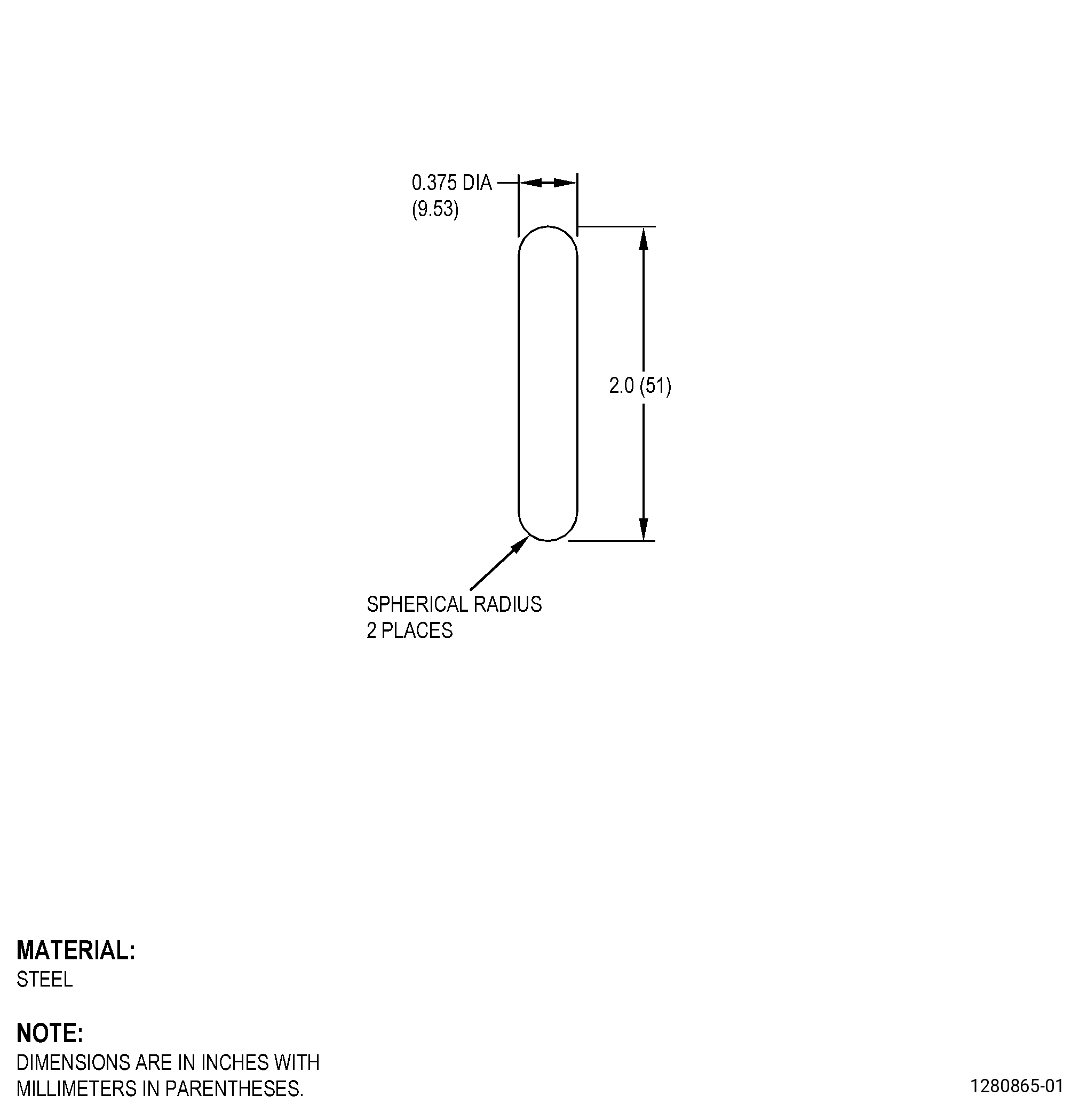
| (4) | A steel rod. Refer to Figure 906. |
| Subtask 72-00-01-350-062 |
| C. | Put a mark on the profile template. Refer to TASK 70-16-00-350-001 (MARKING PRACTICES), TASK 70-16-04-350-019 (VIBRO-PEEN MARKING), Subtask 72-00-01-220-122 (paragraph 3.A., Dimensional Information), Figure 902, and do as follows: |
| (1) | Deleted. |
| NOTE: |
|
| (2) | Make a line on the profile template for each axial angle change. |
| (3) | Write the axial dimensions on the profile template. |
| (4) | Write the angle dimensions for each axial angle change on the profile template. |
| NOTE: |
|
| Subtask 72-00-01-020-001 |
| D. | Remove the forward spinner. Refer to TASK 72-00-01-020-801 (72-00-01, REMOVAL 001). |
| Subtask 72-00-01-220-109 |
| CAUTION: |
|
| E. | Alternative Procedure Available. Use the 11C3406 runout tool to get the abradable shroud runout measurements. Refer to TASK 72-00-01-420-801 (72-00-01, INSTALLATION 001, CONFIG 01), Figure 911, and as follows: |
| NOTE: |
|
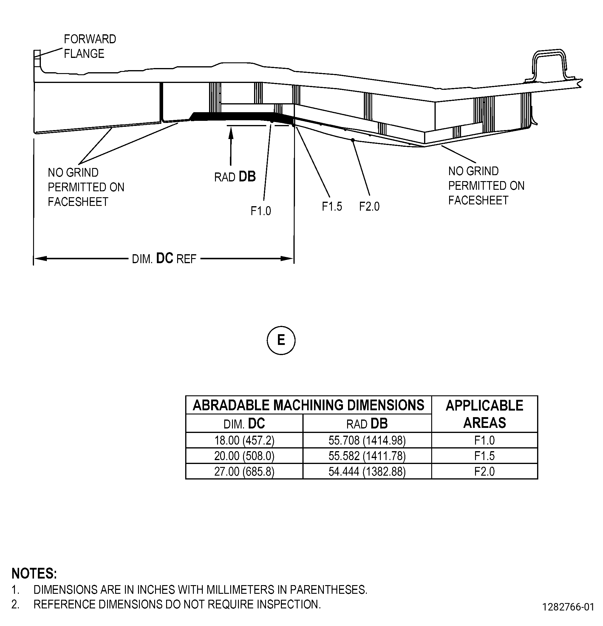
| (1) | Measure the fan blade tip clearances and the abradable shroud runout at F1.0 location, F1.5 location, and F2.0 location. |
| (2) | Use the 11C3406 runout tool, to get the axial locations and runout measurements as follows: |
| (a) | Put a mark on the abradable shroud in the area that you will measure. Refer to TASK 70-16-00-350-001 (MARKING PRACTICES), TASK 70-16-02-350-017 (TEMPORARY MARKING), and as follows: |
| 1 | Find the lowest axial splitline between the forward acoustic liners. |
| NOTE: |
|
| NOTE: |
|
| 2 | Put a mark at the F1.0 location, F1.5 location, and F2.0 location on the abradable shroud surface at the 6:00 o’clock position and do as follows: |
| a | Get the axial locations from the indicator point on the 11C3406 runout tool. |
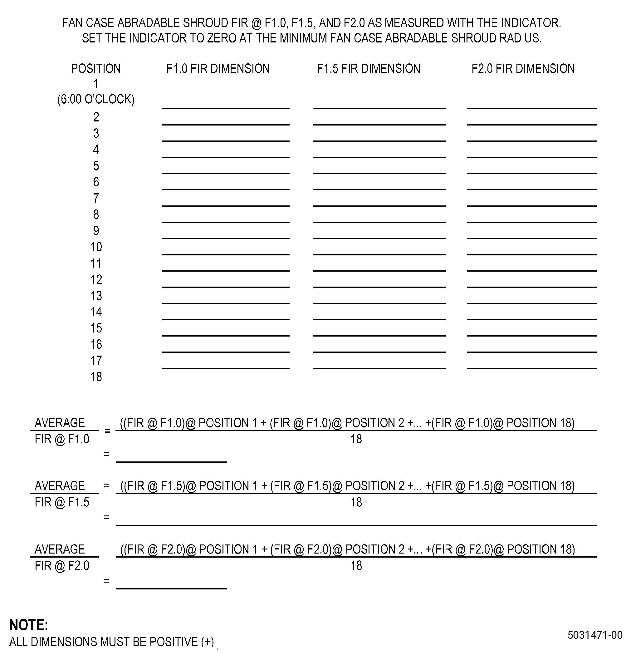
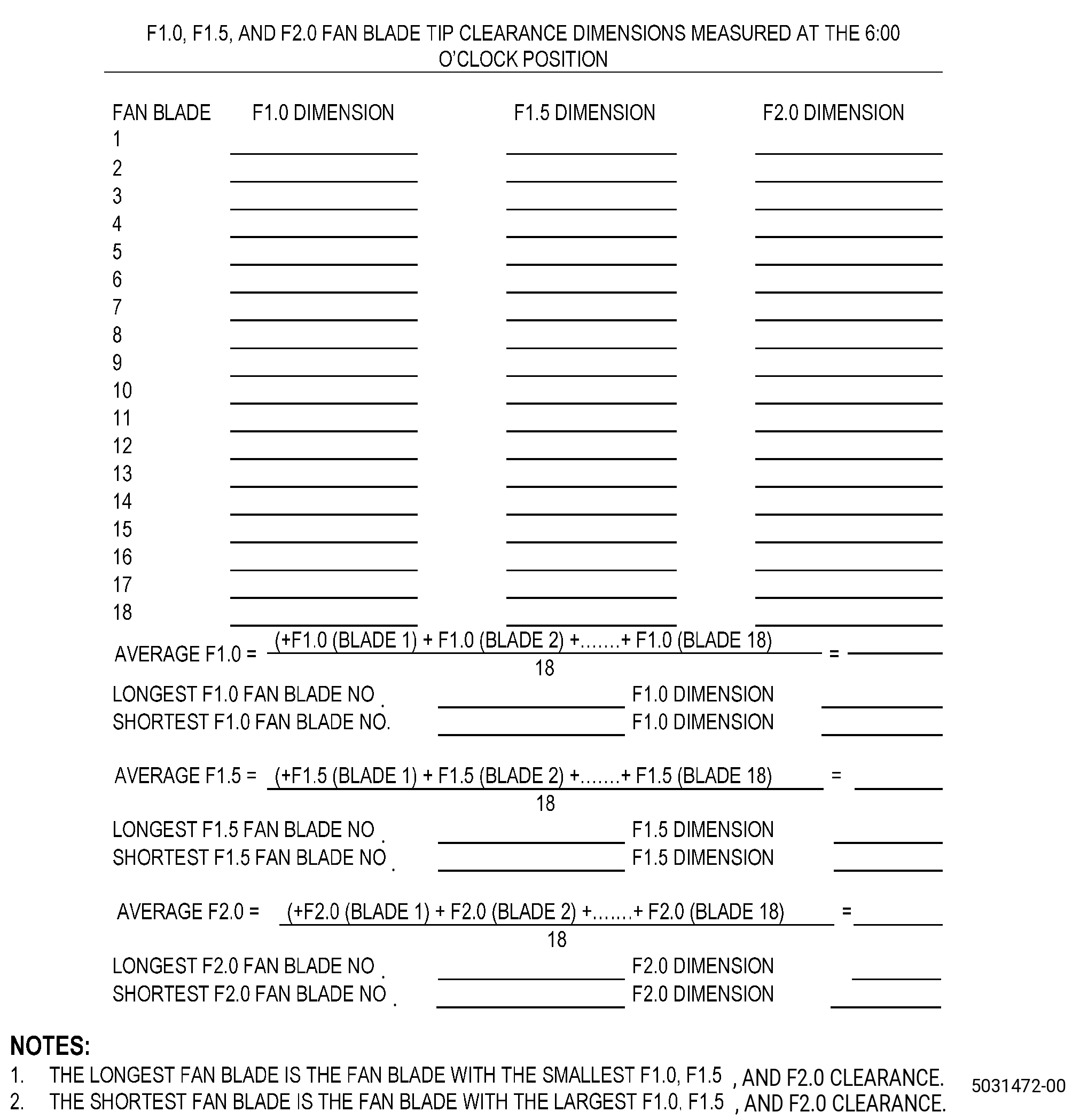
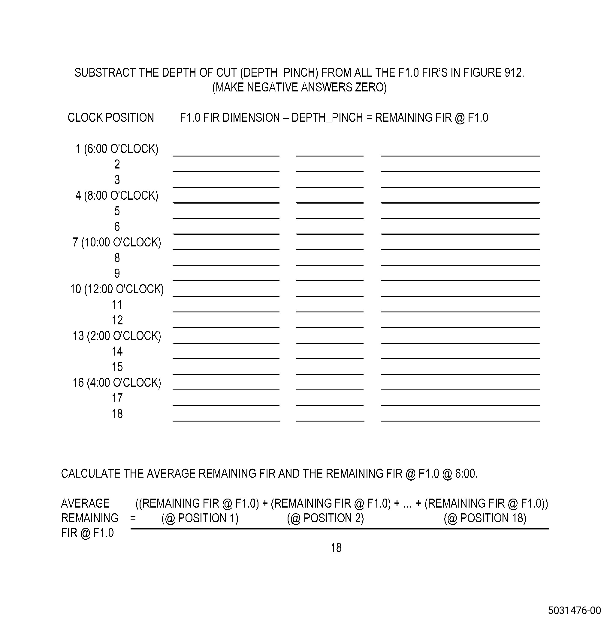
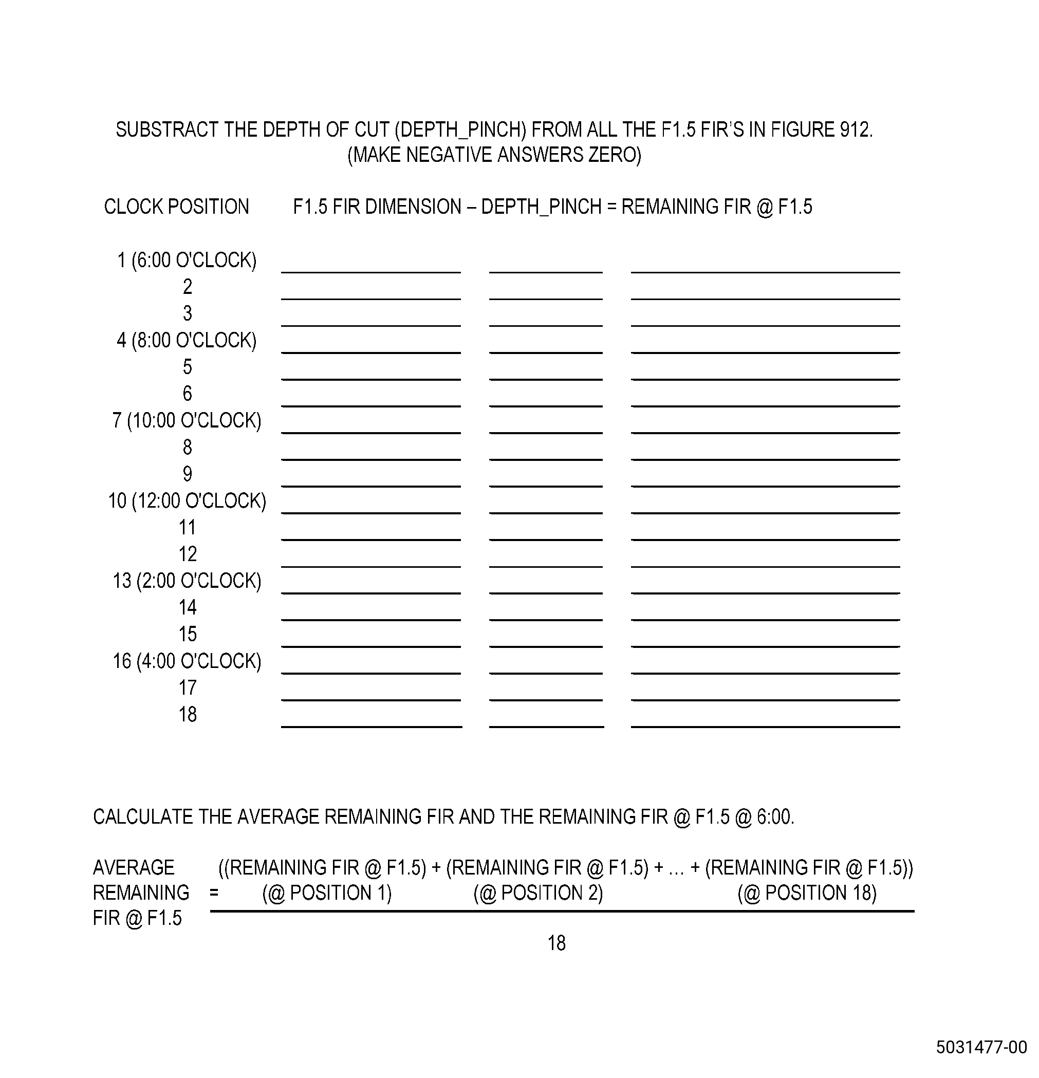
| (3) | Use the tables in Figure 912 and Figure 913 to record the measurements. |
| (4) | Calculate to find the minimum, maximum, and average blade tip clearances. Refer to Figure 915. |
| NOTE: |
|
| Subtask 72-00-01-220-110 |
| E.A. | Alternative Procedure. Use the 11C3001 grind tool to get the abradable shroud runout measurements. Refer to Figure 911 and do as follows: |
| NOTE: |
|
| NOTE: |
|
| (1) | Put a mark on the abradable shroud in the area where you will measure. Refer to TASK 70-16-00-350-001 (MARKING PRACTICES), TASK 70-16-02-350-017 (TEMPORARY MARKING), and as follows: |
| (a) | Find the lowest axial splitline between the forward acoustic liners. |
| NOTE: |
|
| NOTE: |
|
| (b) | Put a mark at the F1.0 location, F1.5 location, and F2.0 location on the abradable shroud surface at the 6:00 o’clock position. |
| CAUTION: |
|
| (2) | Measure the fan blade tip clearances at the F1.0 location, F1.5 location, and F2.0 location as follows: |
| NOTE: |
|
| (a) | Hold the fan blades near the spinner and turn the fan rotor clockwise, FLA, when you move the fan blades. |
| (b) | Turn the fan rotor for two full revolutions. |
| (c) | Turn the fan blade No. 1 to the 6:00 o’clock position. |
| (d) | Measure the fan blade tip clearance. Refer to Figure 911 and as follows: |
| CAUTION: |
|
| 1 | Put a gauge block of 0.200 inch (5.08 mm) in thickness on the F1.0 location mark that you made on the abradable shroud surface and do as follows: |
| a | Use sufficient shims of 0.010 inch (0.25 mm) in thickness to make a 0.200 inch (5.08 mm) thickness. |
| b | Make sure that the shims are fully against the abradable shroud surface. |
| 2 | Use the gauge block and the Starrett No. 270 taper gauge to measure the clearance between the fan blade and the abradable shroud at the F1.5 location. Put the starrett tape gauge in a direction approximately 45 degrees to the forward edge of the abradable from the convex side of the blade and read the measurement on the concave side of the blade. |
| CAUTION: |
|
| 3 | Install the gauge block to let the Starrett No. 270 taper gauge move freely below the fan blade. |
| 4 | Add the gauge block thickness and the taper gauge reading and record the clearance measurement. Refer to Figure 913. |
| (e) | Turn the fan rotor clockwise, FLA, until the adjacent fan blade is in the 6:00 o’clock position. |
| NOTE: |
|
| (f) | Do Subtask 72-00-01-220-110 (paragraph 5.E.A.(2)(d)) thru Subtask 72-00-01-220-110 (paragraph 5.E.A.(2)(e)) again for fan blade No. 2 through fan blade No. 18. |
| (g) | Do Subtask 72-00-01-220-110 (paragraph 5.E.A.(2)(d)) thru Subtask 72-00-01-220-110 (paragraph 5.E.A.(2)(f)) again for the F1.0 location and the F2.0 location. |
| Subtask 72-00-01-020-002 |
| F. | Remove the aft support spinner ring, all the fan platforms, all the fan blades, all the retainers, and the dovetail shims. Refer to TASK 72-00-01-020-801 (72-00-01, REMOVAL 001). |
| Subtask 72-00-01-020-003 |
| G. | Remove all the barrel nuts and the barrel nut retainers from the fan disk. Refer to TASK 72-00-01-020-801 (72-00-01, REMOVAL 001). |
| Subtask 72-00-01-350-069 |
| H. | If necessary, apply masking to the fan case. Refer to TASK 70-46-01-350-030 (MASKING AND CLEANING OF EPOXY AND POLYESTER MATRIX THERMOSETTING COMPOSITE MATERIALS) and as follows: |
| (1) | Apply masking to the fan case areas adjacent to the repair area as follows: |
| (a) | Aft inner and aft outer acoustic liners. |
| (b) | Outlet guide vanes. |
| (c) | Forward acoustic liners. |
| (d) | The acoustically treated areas of the inlet. |
| (e) | All core engine openings, the booster, and the variable bypass valve (VBV) doors. |
| (f) | The face of the fan rotor and the slots between the fan rotor hubs. |
| (2) | Use Composite Masking Method No. 3. |
| (3) | Apply C10-021 plastic tape to make a flap on the rotating joints but make sure that the fan rotor is free to turn. |
| (4) | Apply C10-021 plastic tape to the glass fiber areas forward and aft of the abradable shroud surface. |
| (5) | Apply C10-021 plastic tape to the fan rotor. |
| NOTE: |
|
| Subtask 72-00-01-350-063 |
| I. | Set-up the fan case for grinding by installing the 11C3001 grind tool. Refer to Subtask 72-00-01-350-061 (paragraph 4.A.). |
| Subtask 72-00-01-350-064 |
| J. | Put a mark on the abradable shroud in the area where you will machine. Refer to TASK 70-16-00-350-001 (MARKING PRACTICES), TASK 70-16-02-350-017 (TEMPORARY MARKING), and as follows: |
| (1) | Put a mark at the F1.0 location, F1.5 location, and F2.0 location on the abradable shroud surface at the 6:00 o’clock position as follows: |
| (a) | Find the lowest axial splitline between the forward acoustic liners. |
| NOTE: |
|
| NOTE: |
|
| (b) | Put a mark on the abradable shroud repair area along the full axial length at the 6:00 o’clock position. |
| (c) | Put an X mark on the 6:00 o’clock axial mark on the abradable shroud at the F1.0 location, F1.5 location, and F2.0 location. Refer to Figure 911. |
| NOTE: |
|
| (d) | Put a mark on the 6:00 o’clock position axial mark on the abradable shroud for all the axial positions as follows: |
| Subtask 72-00-01-220-111 |
| 1 | Alternative Procedure Available. Use the profile template to get the axial measurements. Refer to Figure 902. |
| Subtask 72-00-01-220-112 |
| 1.A. | Alternative Procedure. Use a measuring tape to get the axial measurements. Refer to Figure 902. |
| Subtask 72-00-01-350-070 |
| (e) | Write the axial measurement and angle for each angle change between the marks. |
| Subtask 72-00-01-350-065 |
| K. | If you did not get the runout measurements in Subtask 72-00-01-220-109 (paragraph 5.E.), do as follows: |
| NOTE: |
|
| (1) | Put a mark on the abradable shroud surface to find the runout measurement locations. Refer to TASK 70-16-00-350-001 (MARKING PRACTICES), TASK 70-16-02-350-017 (TEMPORARY MARKING), and as follows: |
| (a) | Use a C05-003 pen or C10-021 plastic tape to make the location marks. |
| (b) | Start at the 6:00 o'clock position. |
| (c) | Make 18 equally spaced marks around the fan case to identify the runout measurement locations. |
| NOTE: |
|
| (2) | Set-up the 11C3001 grind tool and the indicators (item 110) for measuring runout. Refer to Subtask 72-00-01-350-061 (paragraph 4.A.). |
| (3) | Put the indicator (item 110) tip on the axial mark that you will measure. |
| (4) | Make sure that the indicator (item 110) is free to move at least 0.200 inch (5.08 mm) up and down. |
| (5) | Hold the 11C3001 grind tool to turn the fan rotor clockwise, FLA |
| (6) | Turn the fan disk two complete turns as follows: |
| (a) | Make sure that the indicator (item 110) reads zero at the same location of each turn before you measure the runouts. |
| NOTE: |
|
| (7) | Make the abradable shroud runout measurements at the F1.0 location, F1.5 location, and F2.0 location as follows: |
| (a) | Put the indicator (item 110) tip on the axial mark on the abradable shroud and make the digital display (item 78) read zero. |
| (b) | Hold the 11C3001 grind tool, to turn the fan rotor, and do as follows: |
| 1 | Read the display on the electrical remote display unit to the dial indicator. Refer to the Starrett instruction book to use the electrical remote display unit, and do as follows: |
| NOTE: |
|
| a | If necessary, you can move indicator tip in the opposite direction. |
| b | Make sure that the indicator value decreases as the fan case radius decreases. |
| 2 | Find the minimum case radius at the axial position that you will measure. |
| (c) | Make the electronic display show zero at the minimum case radius. |
| NOTE: |
|
| (d) | Turn the fan rotor clockwise, FLA, to put the indicator (item 110) at the 6:00 o'clock position. |
| (e) | Record the runout measurements in the table. Refer to Figure 912. |
| (f) | Turn the fan rotor clockwise, FLA, until the indicator (item 110) is in position at the adjacent mark. |
| (g) | Do Subtask 72-00-01-350-065 (paragraph 5.K.(7)(e)) thru Subtask 72-00-01-350-065 (paragraph 5.K.(7)(f)) again until you get all 18 runout dimensions around the abradable shroud. |
| (h) | Do Subtask 72-00-01-350-065 (paragraph 5.K.(3)) thru Subtask 72-00-01-350-065 (paragraph 5.K.(7)(g)) again for the remaining axial locations. |
| (8) | Calculate to find the minimum, maximum, and average blade tip clearances. Refer to Figure 915. |
| NOTE: |
|
| Subtask 72-00-01-350-071 |
| WARNING: |
|
| WARNING: |
|
| CAUTION: |
|
| L. | Alternative Procedure Available. Remove the abradable shroud from the fan case damaged areas as follows: |
| NOTE: |
|
| (1) | If the trenchfiller facesheet is damaged, the abradable shroud is not repairable with this procedure. Refer to TASK 72-00-01-300-801 (72-00-01, REPAIR 003). |
| (2) | Adjust the axial cross slide (item 5) to the angle segment for the axial location that you will machine. Refer to Figure 902, Figure 907, and do as follows: |
| (a) | Loosen the 4 cap screws (item 49) that attach the axial cross slide (item 5). |
| (b) | Put the ball-lock pin (item 22) in the correct location for the angle segment that you will machine. Refer to Figure 908. |
| (c) | Tighten the 4 cap screws (item 49) that attach the axial cross slide (item 5). |
| CAUTION: |
|
| (3) | If you cannot see the glass fiber layer, find the depth of cut of the router cutter (item 24) as follows: |
| WARNING: |
|
| (a) | Carefully sand down to the adhesive in a local area manually or with a small belt sander and do as follows: |
| NOTE: |
|
| 1 | Stop when you see the adhesive. |
| (b) | Make an allowance for the fan case runout when you set the router cutter (item 24) depth. |
| (4) | Start the vacuum hose (item 34). |
| WARNING: |
|
| WARNING: |
|
| (5) | Start the router cutter (item 24). |
| (6) | Move the router cutter (item 24) with the radial cross slide (item 6) to a sufficient depth to remove the remaining damaged abradable material. |
| CAUTION: |
|
| (7) | Machine the abradable shroud as follows: |
| NOTE: |
|
| (a) | Machine a minimum quantity of C01-161 abradable material to remove the damage and do as follows: |
| CAUTION: |
|
| 1 | Move the 11C3001 grind tool, and the fan rotor to make circumferential cuts. |
| 2 | Move the router axially on the cross slide to cut out the damaged area. |
| 3 | Make sure that the edges of the cavity have straight sides or are undercut. Refer to Figure 909. |
| (8) | Stop the router cutter (item 24). |
| (9) | Do Subtask 72-00-01-350-071 (paragraph 5.L.(2)) thru Subtask 72-00-01-350-071 (paragraph 5.L.(8)) again to remove all the damage. |
| WARNING: |
|
| (10) | If necessary, sand the abradable shroud with C10-141 abrasive paper and a sanding block to remove the remaining damaged C01-161 abradable material. |
| (11) | Tap the repair area lightly with the steel rod. Listen to the sound it makes and do as follows: |
| NOTE: |
|
| (a) | If you hear a solid click, there is no disbond or delamination. |
| (b) | If you do not hear a solid click, there is a disbond or delamination. |
| (12) | If you find a disbond or delamination, do Subtask 72-00-01-350-071 (paragraph 5.L.(2)) thru Subtask 72-00-01-350-071 (paragraph 5.L.(11)(b)) again to remove all the disbonds or delaminations. |
| Subtask 72-00-01-350-072 |
| WARNING: |
|
| WARNING: |
|
| CAUTION: |
|
| L.A. | Alternative Procedure. Remove the abradable shroud damaged area as follows: |
| (1) | Use a router or small belt sander to remove the remaining defective C01-161 abradable material down to C01-161 abradable material that is correctly bonded to the fan case. |
| NOTE: |
|
| (2) | If you cannot see the glass fiber layer, find the depth of cut of the router as follows: |
| (a) | Carefully sand down to the adhesive in a local area manually or with a small belt sander and do as follows: |
| NOTE: |
|
| 1 | Stop when you see the adhesive. |
| (3) | Make sure that the edges of the cavity have straight sides or are undercut by a small quantity. Refer to Figure 909. |
| (4) | If necessary, sand the abradable shroud with C10-141 abrasive paper to remove the remaining damaged C01-161 abradable material. |
| (5) | Tap the repair area lightly with the steel rod. Listen to the sound it makes and do as follows: |
| NOTE: |
|
| (a) | If you hear a solid click, there is no disbond or delamination. |
| (b) | If you do not hear a solid click, there is a disbond or delamination. |
| (6) | If you find a disbond or delamination, do Subtask 72-00-01-350-072 (paragraph 5.L.A.(1)) thru Subtask 72-00-01-350-072 (paragraph 5.L.A.(5)(b)) again to remove all the disbonds. |
| Subtask 72-00-01-160-009 |
| M. | Remove all the unwanted material from the repair area with a vacuum cleaner. |
| Subtask 72-00-01-360-010 |
| N. | Look for areas moist with water in the abradable shroud repair area and do as follows: |
| NOTE: |
|
| (1) | Dry the abradable shroud areas moist with water. Refer to TASK 70-46-02-360-002 (DRYING OF THERMOSETTING COMPOSITE MATERIALS) and as follows: |
| Subtask 72-00-01-360-063 |
| (a) | Alternative Procedure Available. Use Absorbed Moisture Removal - Method 3 (Hot Air Dryer). |
| Subtask 72-00-01-360-064 |
| (a).A. | Alternative Procedure. Use Absorbed Moisture Removal - Method 5 (Oven). |
| Subtask 72-00-01-370-025 |
| (b) | Attach a thermocouple to the moist area. |
| WARNING: |
|
| (c) | Increase the temperature of the repair area to 180°F (82.2°C) maximum. |
| (d) | Keep the repair area at a temperature of 180°F (82.2°C) maximum until you cannot see the water. |
| (e) | Continue to dry the repair area for 30 more minutes at 180°F (82.2°C) maximum. |
| Subtask 72-00-01-220-113 |
| O. | If you can see the glass fiber layer in the abradable shroud area as follows: |
| (1) | Do an inspection of the glass fiber surface for damage as follows: |
| (a) | If the glass fiber layer is damaged, the abradable shroud is not repairable with this procedure. Refer to TASK 72-00-01-300-801 (72-00-01, REPAIR 003). |
| Subtask 72-00-01-140-011 |
| WARNING: |
|
| (2) | Sand the fan case with C10-141 abrasive paper to make the glass fiber surface smooth. |
| NOTE: |
|
| Subtask 72-00-01-350-066 |
| P. | Clean the abradable shroud repair area. Refer to TASK 70-46-01-350-030 (MASKING AND CLEANING OF EPOXY AND POLYESTER MATRIX THERMOSETTING COMPOSITE MATERIALS) and as follows: |
| WARNING: |
|
| (1) | Remove the dust from the repair area with compressed air that contains no oil. |
| (2) | Use Composite Cleaning Method No. 5. |
| Subtask 72-00-01-110-017 |
| WARNING: |
|
| (3) | Use C04-035 isopropyl alcohol. |
| Subtask 72-00-01-350-067 |
| Q. | Apply masking to the abradable shroud repair area. Refer to TASK 70-46-01-350-030 (MASKING AND CLEANING OF EPOXY AND POLYESTER MATRIX THERMOSETTING COMPOSITE MATERIALS) and as follows: |
| (1) | Use Composite Masking Method No. 3. |
| (2) | If necessary, apply masking to the repair area until you apply the C01-161 abradable material as follows: |
| (a) | Use Composite Masking Method No. 4. |
| Subtask 72-00-01-360-011 |
| WARNING: |
|
| WARNING: |
|
| CAUTION: |
|
| CAUTION: |
|
| R. | Mix the C01-161 abradable material. Refer to Figure 905 as follows: |
| (1) | If you stored the C01-161 abradable material in a freezer, let the C01-161 abradable material increase to room temperature before you open the container. |
| Subtask 72-00-01-360-012 |
| (2) | Alternative Procedure Available. Prepare the C01-161 abradable material in the 1.5 lb (0.7 kg), 1 pint (0.473 liters), kit as follows: |
| CAUTION: |
|
| (a) | Put each component of the C01-161 abradable material on a clean, metal plate and mix each component individually with spatulas. |
| NOTE: |
|
| (b) | Make sure that you mix fully each component of the C01-161 abradable material before you mix them together. |
| NOTE: |
|
| (c) | Use a spatula to mix the resin and catalyst until you can see no streaks of the two components. |
| NOTE: |
|
| NOTE: |
|
| (d) | The pot life of the C01-161 abradable material will be approximately 20 minutes at 77°F (25°C). |
| NOTE: |
|
| Subtask 72-00-01-360-013 |
| (2).A. | Alternative Procedure. Prepare the C01-161 abradable material in the Semkit mixer style cartridge. Refer to Figure 910 and do as follows: |
| (a) | Remove the cinch tape from the cartridge body. |
| (b) | Pull the dasher rod up to the neck end of the cartridge to get the aluminum foil barrier apart from the mixing dasher. |
| (c) | Push the cartridge sides in the area of the aluminum foil barrier to cause damage to it. |
| (d) | Push the dasher rod to the plunger end of the cartridge to remove the damaged aluminum foil barrier. |
| (e) | Put the dasher rod onto the spindle of the Semkit mixer. |
| (f) | Turn on the Semkit mixer. |
| (g) | Hold the cartridge body and push and pull the cartridge body up and down for 4 minutes. |
| (h) | Make sure that the dasher rod touches the end of the cartridge at the two ends of the travel. |
| (i) | Complete a minimum of 120 travels in the 4 minutes. |
| (j) | Remove the bottom cap. |
| (k) | Push the dasher rod to the plunger end of the cartridge and hold the cartridge firmly at the plunger end. |
| (l) | Turn the dasher rod counterclockwise to disconnect the dasher rod from the mixing dasher. |
| (m) | Remove the dasher rod from the cartridge. |
| (n) | Put the nozzle into the neck end of the cartridge. |
| (o) | Put the cartridge into a Semkit dispensing gun. |
| (p) | Make sure that you remove all the C01-161 abradable material from the cartridge in 2 minutes or less after you mixed it. |
| (q) | You can apply the C01-161 abradable material to the fan case or on a clean, dry surface. |
| NOTE: |
|
| NOTE: |
|
| NOTE: |
|
| Subtask 72-00-01-350-073 |
| S. | Rub the C01-161 abradable material on all of the surfaces of the repair areas. Refer to Figure 902, Figure 905, and do as follows: |
| WARNING: |
|
| (1) | Deleted |
| (2) | Use force to rub the C01-161 abradable material to fully wet all the surfaces of the repair area. |
| (3) | Use a spatula to push the C01-161 abradable material on the repair area as follows: |
| (a) | Hold the spatula at a low angle to prevent caught air in the C01-161 abradable material. |
| (b) | Apply a layer of C01-161 abradable material approximately 0.10 inch (2.5 mm) in thickness at a time. |
| NOTE: |
|
| (4) | If necessary, you can use a stiff bristle C10-108 brush to apply the C01-161 abradable material as follows: |
| WARNING: |
|
| (a) | Use scissors to cut the bristles of a C10-108 brush to make the stiff bristle C10-108 brush. |
| (5) | Use the spatula to make the repair area smooth and remove the caught air. |
| (6) | If the repair area is a minimum of 0.10 inch (2.6 mm) in depth, let the C01-161 abradable material cure for a minimum of 1 hour before you apply more C01-161 abradable material. |
| NOTE: |
|
| (7) | If necessary, do Subtask 72-00-01-350-073 (paragraph 5.S.(2)) thru Subtask 72-00-01-350-073 (paragraph 5.S.(6)) again to apply more C01-161 abradable material and increase the thickness to above the height of the remaining C01-161 abradable material. |
| Subtask 72-00-01-380-002 |
| WARNING: |
|
| T. | Optional Procedure. Cut a piece of C10-051 perforated release film to use as a cover on the abradable shroud repair area. Refer to Figure 902 and do as follows: |
| NOTE: |
|
| NOTE: |
|
| (1) | Make the C10-051 perforated release film approximately 10.0-12.0 inches (254-304 mm) larger all around than the repair area. |
| (2) | Put a small quantity of the C01-161 abradable material at one end of the repair cavity to increase the thickness to above the height of the remaining C01-161 abradable material. |
| (3) | Fill approximately 3.0-4.0 inches (77-101 mm) of the circumferential length of the repair area with C01-161 abradable material at the increased thickness. |
| (4) | Put the C10-051 perforated release film on the repair area and as follows: |
| (a) | The caught air below the C10-051 perforated release film will make voids in the C01-161 abradable material. Carefully apply the C10-051 perforated release film to make the repair area smooth and remove the caught air. |
| (5) | Pull the C10-051 perforated release film tightly and keep in position with C10-136 Flashbreaker tape or with your hands. |
| (6) | Use the profile template or a wooden roller to push the C01-161 abradable material to the contour of the template. |
| (7) | Use shims on the glass fiber surfaces forward and aft of the repair area under the profile template to give extra C01-161 abradable material for the machining procedure after you apply it. |
| NOTE: |
|
| (8) | Do Subtask 72-00-01-380-002 (paragraph 5.T.(1)) thru Subtask 72-00-01-380-002 (paragraph 5.T.(7)) again until the repair area is filled. |
| (9) | Make sure that you do not remove the C10-051 perforated release film until you complete the cure process in Subtask 72-00-01-360-014 (paragraph 5.W.). |
| Subtask 72-00-01-160-010 |
| U. | If necessary, use a C10-182 cleaning cloth to remove the unwanted C01-161 abradable material from the repair area. |
| Subtask 72-00-01-380-003 |
| V. | Monitor the C01-161 abradable material on the abradable shroud repair area and do as follows: |
| (1) | If the C01-161 abradable material moves, use the wooden roller or profile template to push it back to the correct contour. |
| Subtask 72-00-01-360-014 |
| WARNING: |
|
| CAUTION: |
|
| W. | Alternative Procedure Available. Cure the C01-161 abradable material on the abradable shroud repair area. Refer to SAE ARP 5144, Heat Application for Thermosetting Resin Curing, and as follows: |
| (1) | Cure the C01-161 abradable material for a minimum of 24 hours at a minimum temperature of 77°F (25.0°C). |
| NOTE: |
|
| (2) | If the room temperature is less than 77°F (25.0°C), you can use heat lamps or a thermal blanket to increase the temperature to 77°F (25.0°C), and as follows: |
| (a) | Use a thermocouple to monitor the temperature. |
| (b) | Keep the temperature between 77 to 100°F (25 to 38°C). |
| (3) | If the room temperature is above 77°F (25.0°C), do not apply more heat. |
| (4) | For room temperatures other than 77°F (25.0°C), do as follows: |
| Subtask 72-00-01-380-016 |
| (a) | Alternative Procedure Available. Measure the hardness of the C01-161 abradable material. Refer to TASK 70-34-00-200-003 (HARDNESS MEASUREMENT - GENERAL) and as follows: |
| 1 | You can machine or sand the C01-161 abradable material, if it has a shore D hardness of more than 60. |
| Subtask 72-00-01-350-273 |
| WARNING: |
|
| (a).A. | Alternative Procedure. Manually sand the C01-161 abradable material as follows: |
| 1 | You can machine or sand the C01-161 abradable material, if you see a fine dust when it is manually sanded. |
| 2 | Use the profile template, as necessary, to make sure that the manually sanded area agrees with the abradable shroud contour. Refer to Figure 902. |
| Subtask 72-00-01-360-015 |
| WARNING: |
|
| W.A. | Alternative Procedure. Cure the C01-161 abradable material. Refer to SAE ARP 5144, Heat Application for Thermosetting Resin Curing, and as follows: |
| CAUTION: |
|
| (1) | Let the C01-161 abradable material cure for 3 hours at a minimum temperature of 77°F (25.0°C). |
| (2) | If the room temperature is less than 77°F (25.0°C), you can use heat lamps or a thermal blanket to increase the temperature to 77°F (25.0°C) as follows: |
| (a) | Use a thermocouple to monitor the temperature. |
| (b) | Keep the temperature in the range of 77 to 100°F (25.0 to 37.7°C). |
| (3) | If the room temperature is 77°F (25.0°C) or more, do not increase the temperature. |
| CAUTION: |
|
| (4) | Increase the temperature of the C01-161 abradable material to a range of 100 to 120°F (37.8 to 48.8°C) and hold for a minimum of 2 hours as follows: |
| Subtask 72-00-01-370-026 |
| (a) | Alternative Procedure Available. Use a heat lamp, a thermal blanket or a heat gun on the repair area to increase the temperature. |
| Subtask 72-00-01-360-065 |
| (a).A. | Alternative Procedure. Increase the temperature of the repair area. Refer to TASK 70-46-02-360-002 (70-46-02, DRYING OF THERMOSETTING COMPOSITE MATERIALS), and as follows: |
| 1 | Use Absorbed Moisture Removal - Method 5 (Oven). |
| (b) | Use a minimum of three thermocouples equally spaced around the repair area. |
| Subtask 72-00-01-350-068 |
| X. | If you did not use the 11C3001 grind tool, to remove the damaged C01-161 abradable material from the abradable shroud repair area, install the 11C3001 grind tool. Refer to Subtask 72-00-01-350-061 (paragraph 4.A.). |
| Subtask 72-00-01-370-018 |
| CAUTION: |
|
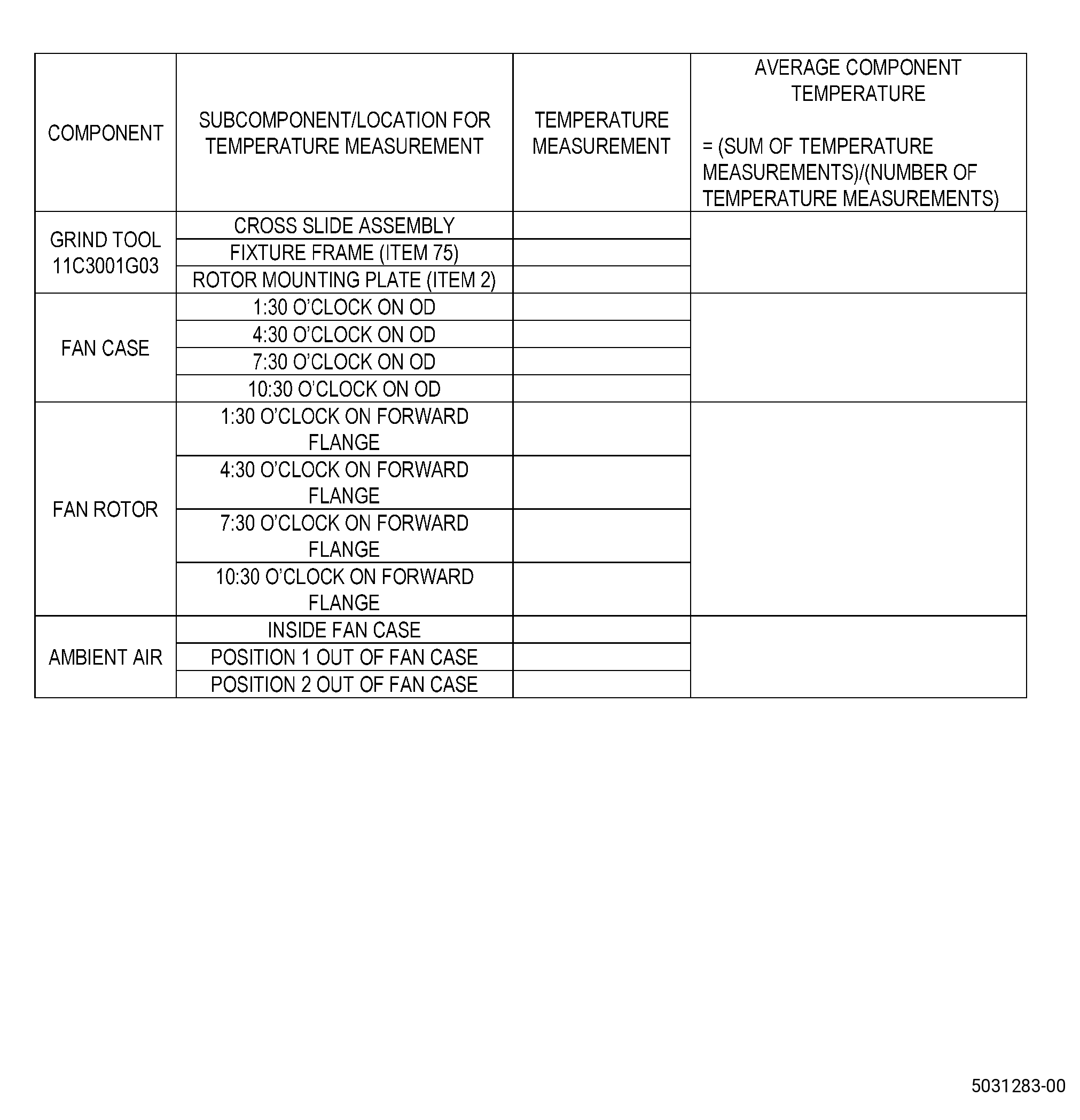
| Y. | Calculate the average temperature of the 11C3001 grind tool, the fan rotor, the fan case, and the ambient air around the engine. Refer to Figure 919 and as follows: |
| NOTE: |
|
| NOTE: |
|
| (1) | Use a thermocouple or a digital thermometer with a probe to measure the average temperature of the 11C3001 grind tool, fan rotor, fan case, and the ambient air around the engine. |
| (2) | Calculate the average temperature of the 11C3001 grind tool and as follows: |
| (a) | Record the temperature of the cross slide assembly, the fixture frame (item 75), and the rotor mounting plate (item 2). |
| (b) | Calculate the average of the recorded temperatures. |
| (3) | Calculate the average temperature of the fan case as follows: |
| (a) | Record the temperature around on the outer diameter of the fan case at the 1:30 o’clock position, the 4:30 o’clock position, the 7:30 o’clock position, and the 10:30 o’clock position. |
| (b) | Calculate the average of the recorded temperatures. |
| (4) | Calculate the average temperature of the fan rotor and do as follows: |
| (a) | Record the temperature around the fan rotor forward flange at the 1:30 o’clock position, the 4:30 o’clock position, the 7:30 o’clock position, and the 10:30 o’clock position. |
| (b) | Calculate the average of the recorded temperatures. |
| (5) | Calculate the average temperature of the ambient air and do as follows: |
| (a) | Record the temperature of the ambient air inside the case and at two positions outside the case. |
| (b) | Calculate the average of the recorded temperatures |
| (6) | The permitted differences in temperature between the 11C3001 grind tool, the fan rotor, the fan case, and the ambient air are as follows: |
| (a) | The difference between the average temperature of the 11C3001 grind tool, and the average temperature of air around the fan case must not be more than 7°F (3.9°C). |
| (b) | The difference between the average temperature of the fan rotor and the average temperature of air around the fan case must not be more than 7°F (3.9°C). |
| (c) | The difference between the average temperature of the fan case and the average temperature of air around the fan case must not be more than 7°F (3.9°C). |
| (d) | The difference between the average temperature of the 11C3001 grind tool and the average temperature of the fan case must no be more than 5°F (2.8°C). |
| (7) | If the differences in average temperature are more than these limits, let the temperature of the components equalize. |
| Subtask 72-00-01-320-001 |
| WARNING: |
|
| Z. | Alternative Procedures Available. Machine the C01-161 abradable material on the abradable shroud repair area to get the correct profile. Refer to Figure 907, Figure 918, and do as follows: |
| NOTE: |
|
| (1) | Put a mark on the abradable shroud surface F1.5 location at the 6:00 o’clock position. Refer to TASK 70-16-00-350-001 (MARKING PRACTICES), TASK 70-16-02-350-017 (TEMPORARY MARKING), Figure 911, and as follows: |
| NOTE: |
|
| (a) | Find the lowest axial splitline between the forward acoustic liners. |
| NOTE: |
|
| NOTE: |
|
| (b) | Put a mark from the forward edge of the glass fiber layer axially across the abradable, at the 6:00 o’clock position. |
| (c) | At the 6:00 o’clock position, use the profile template to put marks on the C01-161 abradable material at each change in angle. Refer to Figure 902. |
| (d) | Put an "X" mark on the 6:00 o’clock position axial mark on the C01-161 abradable material at the F1.0 location, F1.5 location, and F2.0 location. |
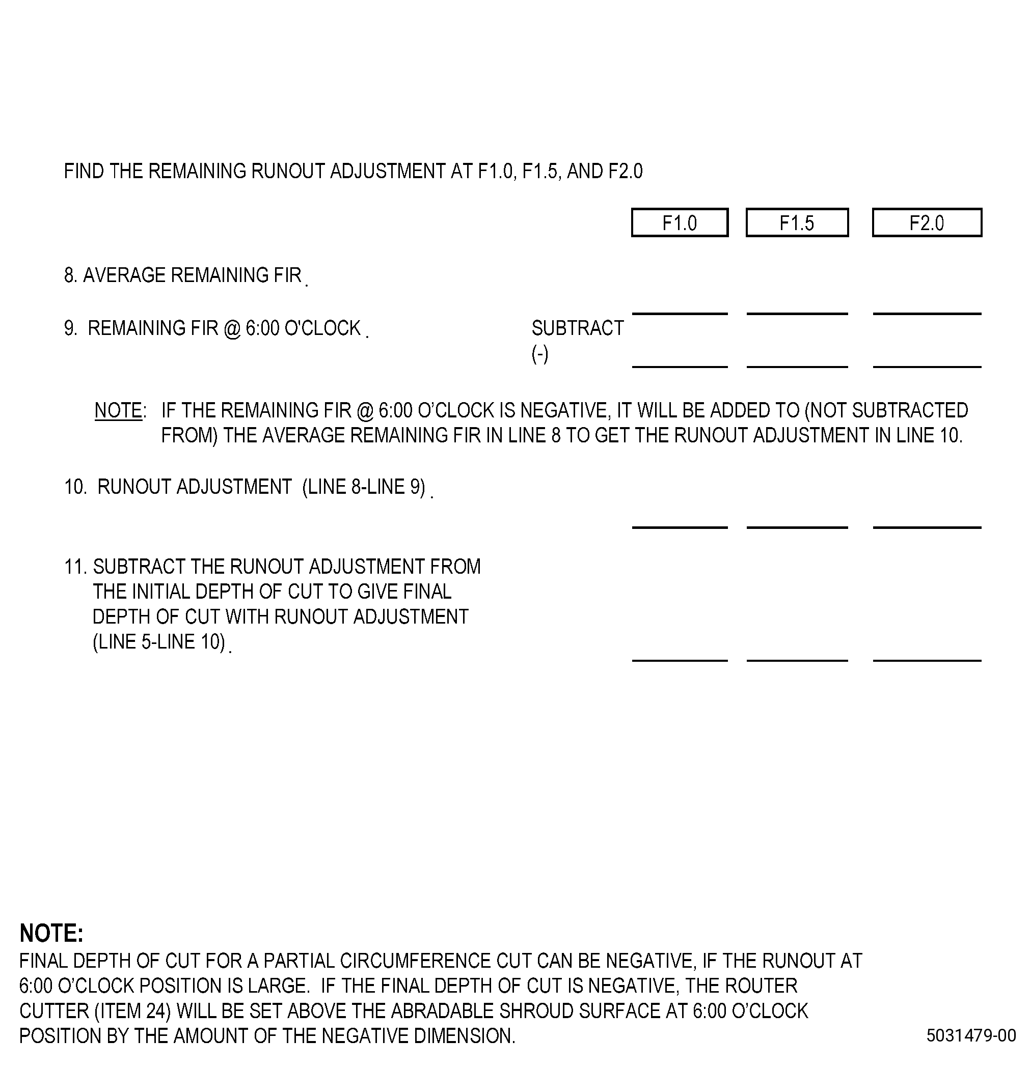
| (2) | Find the depth of cut at the F1.0 location, the F1.5 location, and the F2.0 location. Refer to Figure 917. |
| NOTE: |
|
| (3) | Set the router cutter (item 24) position as follows: |
| (a) | Move the 11C3001 grind tool, until the router cutter (item 24) is at the 6:00 o’clock position. |
| (b) | Adjust the angle of the axial cross slide (item 5) and put the ball-lock pin (item 22) in the preset angle hole for the angle segment that you will machine. Refer to Figure 908 and do as follows: |
| 1 | Tighten the four cap screws (item 49) to keep the axial cross slide (item 5) in the correct position. |
| (c) | Move the axial cross slide (item 5) until the router cutter (item 24) is over the axial mark for the angle segment that you will machine and do as follows: |
| NOTE: |
|
| 1 | Lock the axial cross slide (item 5). |
| (d) | Adjust the radial cross slide (item 6) until the router cutter (item 24) touches the abradable surface and do as follows: |
| 1 | Set the digital display (item 78) to zero and lock the adjustable vernier scale on the radial cross slide (item 6). |
| 2 | Lock the radial cross slide (item 6). |
| (e) | If the adjustment for the nominal depth of cut in Subtask 72-00-01-320-001 (paragraph 5.Z.(2)), is negative, do as follows: |
| 1 | Use shims to set the router cutter (item 24) to the height above the abradable surface. |
| 2 | Continue the repair at Subtask 72-00-01-320-001 (paragraph 5.Z.(3)(p)). |
| (f) | Start the router cutter (item 24). |
| (g) | Use the radial cross slide (item 6) vernier graduations to adjust the router cutter (item 24) depth to a part of the nominal depth of cut. Refer to Figure 917 for the nominal depth. |
| (h) | Turn the 11C3001 grind tool to make a cut approximately 2.0 inches (51 mm) in circumferential length at the 6:00 o’clock position. |
| (i) | Stop the router cutter (item 24). |
| (j) | Use the depth gauge to measure the depth of the cut. Refer to Figure 904 and as follows: |
| 1 | To make the measurements more accurate, put the base of the depth gauge on the more cylindrical (forward) part of the profile and slide the depth gauge circumferentially. |
| (k) | From the measured depth, calculate the remaining depth of cut necessary to get the calculated nominal depth of cut. |
| (l) | Start the router cutter (item 24) and do as follows: |
| 1 | Use the radial cross slide vernier graduations to adjust the router cutter (item 24) depth. |
| (m) | Turn the 11C3001 grind tool again to make a cut approximately 2.0 inches (51 mm) in circumferential length at the 6:00 o’clock position. |
| (n) | Stop the router cutter (item 24). |
| (o) | Use the depth gauge to make sure the depth is no more than 0.005 inch (0.12 mm) of the nominal depth of cut. Refer to Figure 904 and Figure 917. |
| NOTE: |
|
| NOTE: |
|
| (p) | Set the digital display (item 78) to zero and do as follows: |
| 1 | Lock the adjustable vernier scale on the radial cross slide (item 6). |
| 2 | Lock the radial cross slide (item 6). |
| WARNING: |
|
| CAUTION: |
|
| (4) | Start the vacuum hose (item 34) and do as follows: |
| (a) | Start the router cutter (item 24). |
| (b) | Hold the 11C3001 grind tool, near the fan rotor, and do as follows: |
| 1 | Turn the 11C3001 grind tool, very slowly clockwise, FLA. |
| (c) | Turn the 11C3001 grind tool, around the full abradable shroud circumference. |
| (5) | Unlock the axial cross slide (item 5) and do as follows: |
| (a) | Use the axial cross slide (item 5) to move the router cutter (item 24) to a new axial position that has a small overlap with the cut before. |
| (b) | Lock the axial cross slide (item 5). |
| (6) | Hold the 11C3001 grind tool, and do as follows: |
| (a) | Turn the 11C3001 grind tool, very slowly around the abradable shroud circumference, clockwise, FLA. |
| (7) | Do Subtask 72-00-01-320-001 (paragraph 5.Z.(5)) thru Subtask 72-00-01-320-001 (paragraph 5.Z.(6)(a)) again until you get to the axial location mark for the angle segment that you machined. |
| (8) | Stop the router cutter (item 24) and do as follows: |
| (a) | Unlock the radial cross slide (item 6). |
| (b) | Use the radial cross slide (item 6) to move the router cutter (item 24) approximately 0.100 inch (2.54 mm) away from the C01-161 abradable material. |
| (9) | If the repair area extends forward or aft of this angle segment, machine the area of the next angle segment as follows: |
| NOTE: |
|
| (a) | Machine the other angle segments in the abradable shroud repair area in the sequence that follows: |
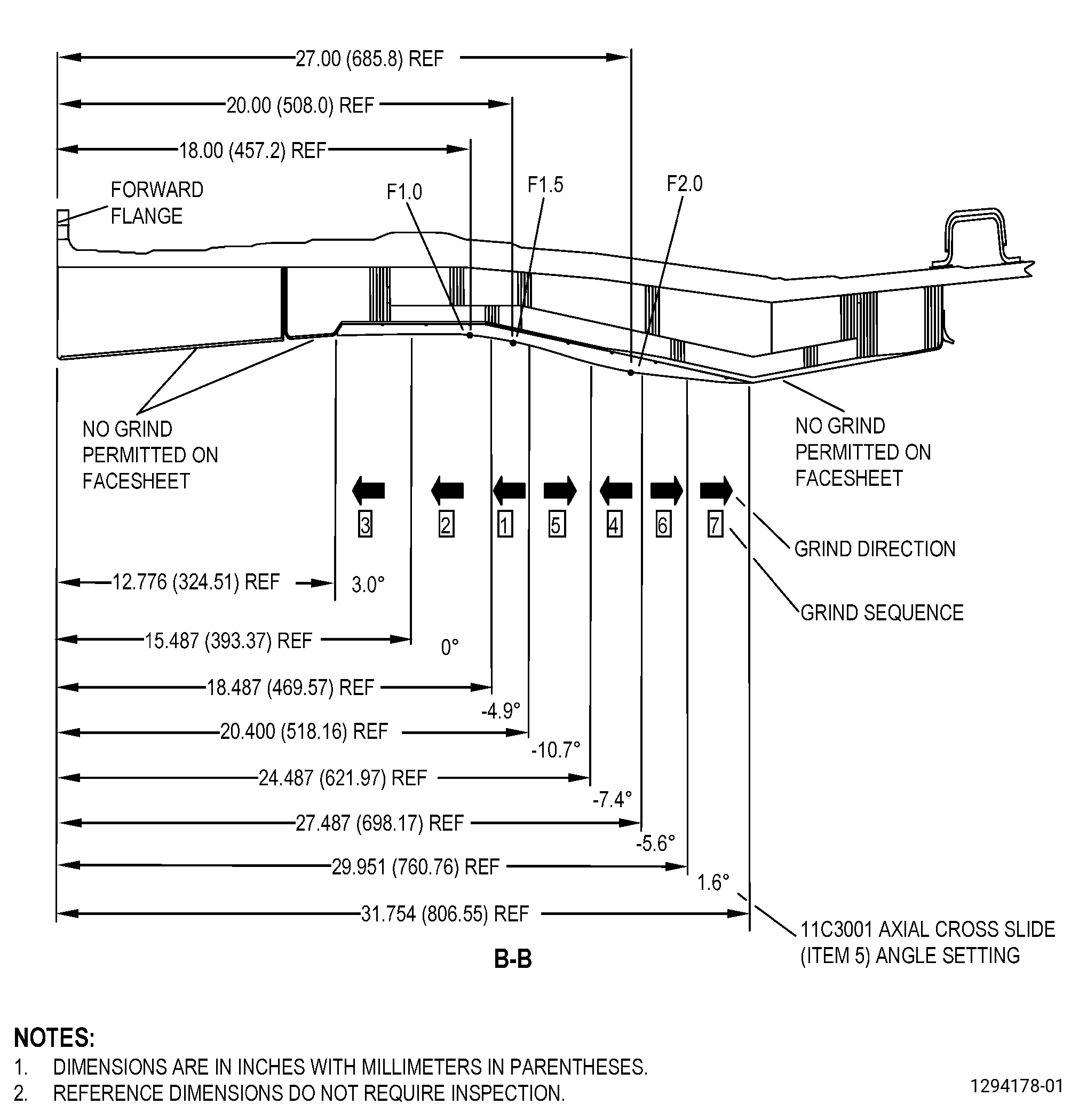
| 1 | -4.9 degree angle, aft to forward, set depth of cut at the F1.5 mark. |
| 2 | 0 degree angle, aft to forward, set depth of cut at the F1.0 mark. |
| 3 | 3.0 degree angle, aft to forward, set depth of cut to blend with a 0 degree segment. |
| 4 | -7.4 degree angle, aft to forward, set depth of cut at the F2.0 mark. |
| 5 | -10.7 degree angle, forward to aft, set depth of cut to blend with the -4.9 degree segment. |
| 6 | -5.6 degree angle, forward to aft, set depth of cut to blend with the -7.4 degree segment. |
| 7 | 1.6 degree angle, forward to aft, set depth of cut to blend with the -5.6 degree segment. |
| (b) | Adjust the angle of the axial cross slide (item 5) and put the ball-lock pin (item 22) in the preset angle hole for the next angle segment that you will machine. Refer to Figure 907, Figure 908, and do as follows: |
| 1 | Tighten the four cap screws (item 49) to keep the axial cross slide (item 5) in the correct position. |
| (c) | Unlock the axial cross slide (item 5) and do as follows: |
| 1 | Use the axial cross slide (item 5) to move the router cutter (item 24) to a new axial position that has a small overlap with the cut before. |
| 2 | Lock the axial cross slide (item 5). |
| (d) | Deleted. |
| (e) | Start the router cutter (item 24). |
| (f) | Use the radial cross slide (item 6) to lower the router cutter (item 24) until it is level with the cut before and do as follows: |
| 1 | Lock the radial cross slide (item 6). |
| NOTE: |
|
| (g) | Do Subtask 72-00-01-320-001 (paragraph 5.Z.(7)) again to machine the C01-161 abradable material in the area of this angle. |
| (h) | Stop the router cutter (item 24) and do as follows: |
| 1 | Unlock the radial cross slide (item 6). |
| 2 | Use the radial cross slide (item 6) to move the router cutter (item 24) approximately 0.100 inch (2.54 mm) away from theC01-161 abradable material. |
| (i) | If the repair area is more than the axial limits of this angle segment, do Subtask 72-00-01-320-001 (paragraph 5.Z.(9)(a)) thru Subtask 72-00-01-320-001 (paragraph 5.Z.(9)(h)2) again to machine the remaining angle segments. |
| (j) | If this is the last angle segment that you will machine, do as follows: |
| CAUTION: |
|
| 1 | Keep the router cutter (item 24) at a minimum of 0.5 inch (13 mm) from the forward glass fiber layer and aft glass fiber layer. |
| WARNING: |
|
| CAUTION: |
|
| 2 | If there is a remaining step or if you replaced the area 0.5 inch (13 mm) or closer to the forward edge or aft edge of the abradable shroud, use C10-141 abrasive paper or a rotary sander to make the C01-161 abradable material smooth to the limits that follow: |
| a | The change from repair area to adjacent abradable shroud surface must be 0.020 inch (0.50 mm) maximum for forward facing surfaces. |
| b | The change from repair area to adjacent fan case surface must be 0.040 inch (1.01 mm) maximum for aft facing surfaces. |
| c | Keep heat input to a minimum. |
| Subtask 72-00-01-320-002 |
| WARNING: |
|
| Z.A. | Alternative Procedure. Machine the C01-161 abradable material on the abradable shourd repair area to get the correct profile. Refer to Figure 907, Figure 918, and as follows: |
| NOTE: |
|
| (1) | Make sure that the difference between the average temperature of the 11C3001 grind tool and the average temperature of the fan case is not more than 5°F (2.8°C). Refer to Subtask 72-00-01-370-018 (paragraph 5.Y.(1)) thru Subtask 72-00-01-370-018 (paragraph 5.Y.(3)(b)) and as follows: |
| (a) | If the average temperature measurement difference is more than this limit, let the temperature of the components equalize. |
| NOTE: |
|
|
| NOTE: |
|
| NOTE: |
|
| (2) | Calculate the local depth of cut for the repair area as follows: |
| (a) | Move the indicator (item 110) to the actual abradable surface below the lower edge of the repair area. |
| (b) | Put a mark on the fan case at the position of the indicator (item 110). Refer to TASK 70-16-00-350-001 (MARKING PRACTICES) and TASK 70-16-02-350-017 (TEMPORARY MARKING). |
| NOTE: |
|
| (c) | Set the indicator (item 110) to zero. |
| (d) | Move the indicator (item 110) to the actual abradable surface above the upper edge of the repair area. |
| (e) | Record the reading and do as follows: |
| 1 | If the reading is 0.010 inch (0.25 mm) or less, positive or negative, you can use this alternative procedure. |
| 2 | If the reading is more than 0.010 inch (0.26 mm), positive or negative, you cannot use this alternative procedure. |
| (f) | Divide the reading by two to get the local depth of cut. |
| NOTE: |
|
| (3) | Put a mark on the abradable shroud. Refer to TASK 70-16-00-350-001 (MARKING PRACTICES), TASK 70-16-02-350-017 (TEMPORARY MARKING), Figure 902, and as follows: |
| (a) | At the indicator position mark, use the profile template to put marks for the forward and aft axial limits for the angle segments that you will machine. |
| (4) | Set the router cutter (item 24) depth as follows: |
| (a) | Adjust the angle of the axial cross slide (item 5) and put the ball-lock pin (item 22) in the preset angle hole for the first angle segment that you will machine. Refer to Figure 902, Figure 908, and do as follows: |
| 1 | Tighten the four cap screws (item 49) to keep the axial cross slide (item 5) in the correct position. |
| NOTE: |
|
| (b) | Move the 11C3001 grind tool until the router cutter (item 24) is at the lower edge of the repair area. |
| (c) | Move the axial cross slide (item 5) until the router cutter (item 24) is at the indicator position mark. |
| (d) | Lock the axial cross slide (item 5). |
| (e) | Adjust the radial cross slide (item 6) until the router cutter (item 24) touches the abradable surface. |
| (f) | Set the digital display (item 78) to zero and do as follows: |
| 1 | Lock the adjustable vernier scale on the radial cross slide (item 6). |
| 2 | Lock the radial cross slide (item 6). |
| (g) | If the local depth of cut from Subtask 72-00-01-320-002 (paragraph 5.Z.A.(2)(f)) is negative, use shims to set the router cutter (item 24) to the height above the abradable surface and as follows: |
| 1 | Continue with Subtask 72-00-01-320-002 (paragraph 5.Z.A.(5)). |
| (h) | Start the router cutter (item 24). |
| (i) | Use the radial cross slide (item 6) vernier graduations to adjust the router cutter (item 24) depth to the calculated depth. |
| (j) | Turn the 11C3001 grind tool to make a cut approximately 2.0 inches (51 mm) in circumferential length. |
| (k) | Stop the router cutter (item 24). |
| (l) | Use the depth gauge to make sure that the depth is correct to no more than 0.005 inch (0.12 mm) of the depth of cut from Subtask 72-00-01-320-002 (paragraph 5.Z.A.(2)(f)). Refer to Figure 904. |
| NOTE: |
|
| (m) | Set the digital display (item 78) to zero and lock the adjustable vernier scale on the radial cross slide (item 6). |
| (n) | Lock the radial cross slide (item 6). |
| CAUTION: |
|
| CAUTION: |
|
| (5) | Start the vacuum hose (item 34). |
| (6) | Start the router cutter (item 24). |
| (7) | Turn the 11C3001 grind tool very slowly around the abradable shroud from the lower edge of the repair area to the upper edge. |
| (8) | Unlock the axial cross slide (item 5). |
| (9) | Use the axial cross slide (item 5) to move the router cutter (item 24) to a new axial position that has a small overlap with the cut before. |
| (10) | Lock the axial cross slide (item 5). |
| (11) | Pull the 11C3001 grind tool, around the abradable shroud very slowly across the repair area. |
| (12) | Do Subtask 72-00-01-320-002 (paragraph 5.Z.A.(8)) thru Subtask 72-00-01-320-002 (paragraph 5.Z.A.(11)) again until you get to the axial mark for the angle segment you machined. |
| (13) | Stop the router cutter (item 24). |
| (14) | Unlock the radial cross slide (item 6). |
| (15) | Use the radial cross slide (item 6) to move the router cutter (item 24) approximately 0.100 inch (2.54 mm) away from the C01-161 abradable material. |
| (16) | If the repair area extends forward or aft of this angle segment, machine the area of the next angle segment as follows: |
| NOTE: |
|
| (a) | Machine the other angle segments in the abradable shroud repair area in the sequence that follows: |
| NOTE: |
|
| 1 | -4.9 degree angle, aft to forward, set depth of cut at F1.5 mark. |
| 2 | 0 degree angle, aft to forward, set depth of cut at F1.0 mark. |
| 3 | 3.0 degree angle, aft to forward, set depth of cut to blend with 0 degree segment. |
| 4 | -7.4 degree angle, aft to forward, set depth of cut at F2.0 mark. |
| 5 | -10.7 degree angle, forward to aft, set depth of cut to blend with -4.9 degree segment. |
| 6 | -5.6 degree angle, forward to aft, set depth of cut to blend with -7.4 degree segment. |
| 7 | 1.6 degree angle, forward to aft, set depth of cut to blend with -5.6 degree segment. |
| (b) | Adjust the angle of the axial cross slide (item 5) and put the ball-lock pin (item 22) in the preset angle hole for the next angle segment that you will machine. Refer to Figure 907, Figure 908, and do as follows: |
| 1 | Tighten the four cap screws (item 49) to keep the axial cross slide (item 5) in the correct position. |
| (c) | Unlock the axial cross slide (item 5). |
| (d) | Use the axial cross slide (item 5) to move the router cutter (item 24) to a new axial position that has a small overlap with the cut before and do as follows: |
| NOTE: |
|
| 1 | Lock the axial cross slide (item 5). |
| (e) | Put a mark on the abradable shroud. Refer to TASK 70-16-00-350-001 (MARKING PRACTICES), TASK 70-16-02-350-017 (TEMPORARY MARKING), Figure 902, and as follows: |
| 1 | If necessary, use the profile template to put a mark on the C01-161 abradable material at the axial limits of this angle segment. |
| (f) | Start the router cutter (item 24). |
| (g) | Lower the router cutter (item 24) until it is level with the cut before. |
| NOTE: |
|
| (h) | Lock the radial cross slide (item 6). |
| NOTE: |
|
| (i) | Do Subtask 72-00-01-320-002 (paragraph 5.Z.A.(12)) again to machine the C01-161 abradable material in the area of this angle segment. |
| (j) | Stop the router cutter (item 24). |
| (k) | Unlock the radial cross slide (item 6). |
| (l) | Use the radial cross slide (item 6) to move the router cutter (item 24) approximately 0.100 inch (2.54 mm) away from the abradable. |
| (m) | If the abradable shroud repair area extends forward or aft of this angle segment, do Subtask 72-00-01-320-002 (paragraph 5.Z.A.(16)(a)) thru Subtask 72-00-01-320-002 (paragraph 5.Z.A.(16)(l)) again to machine the remaining angle segments. |
| (n) | If this is the last angle segment that you will machine, do as follows: |
| CAUTION: |
|
| 1 | Keep the router cutter (item 24) a minimum of 0.5 inch (13 mm) from the forward glass fiber layer and the aft glass fiber layer. |
| Subtask 72-00-01-140-012 |
| WARNING: |
|
| CAUTION: |
|
| 2 | If there is a remaining step or if you replaced the area 0.5 inch (13 mm) or closer to the forward edge or aft edge of the C01-161 abradable material, use C10-141 abrasive paper or a rotary sander to make the C01-161 abradable material smooth to the limits that follow: |
| a | Deleted. |
| b | The change from the repair area to the adjacent abradable shroud surface must be 0.020 inch (0.50 mm) maximum for forward facing surfaces. |
| c | The change from the repair area to the adjacent abradable shroud surface must be 0.040 inch (1.01 mm) maximum for aft facing surfaces. |
| d | Keep heat input to a minimum. |
| Subtask 72-00-01-320-003 |
| WARNING: |
|
| WARNING: |
|
| Z.B. | Alternative Procedure. Machine the C01-161 abradable material on the abradable shroud repair area to get the correct profile. Refer to Figure 907, Figure 918, and do as follows: |
| NOTE: |
|
| (1) | Calculate the depth of cut at the F1.0 location, F1.5 location, and F2.0 location as follows: |
| WARNING: |
|
| (a) | If necessary, sand the abradable shroud with C10-141 abrasive paper to make a flat surface at the measurement location. |
| NOTE: |
|
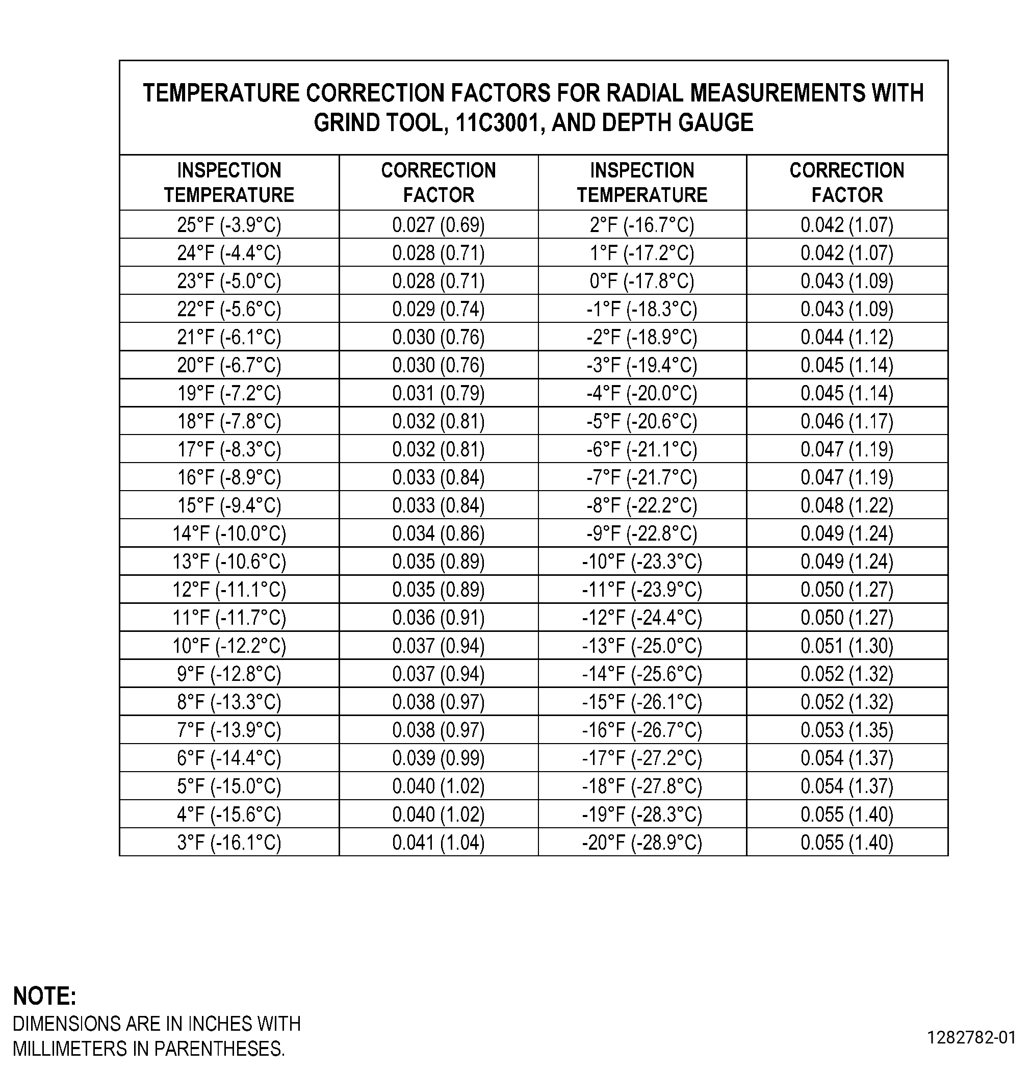
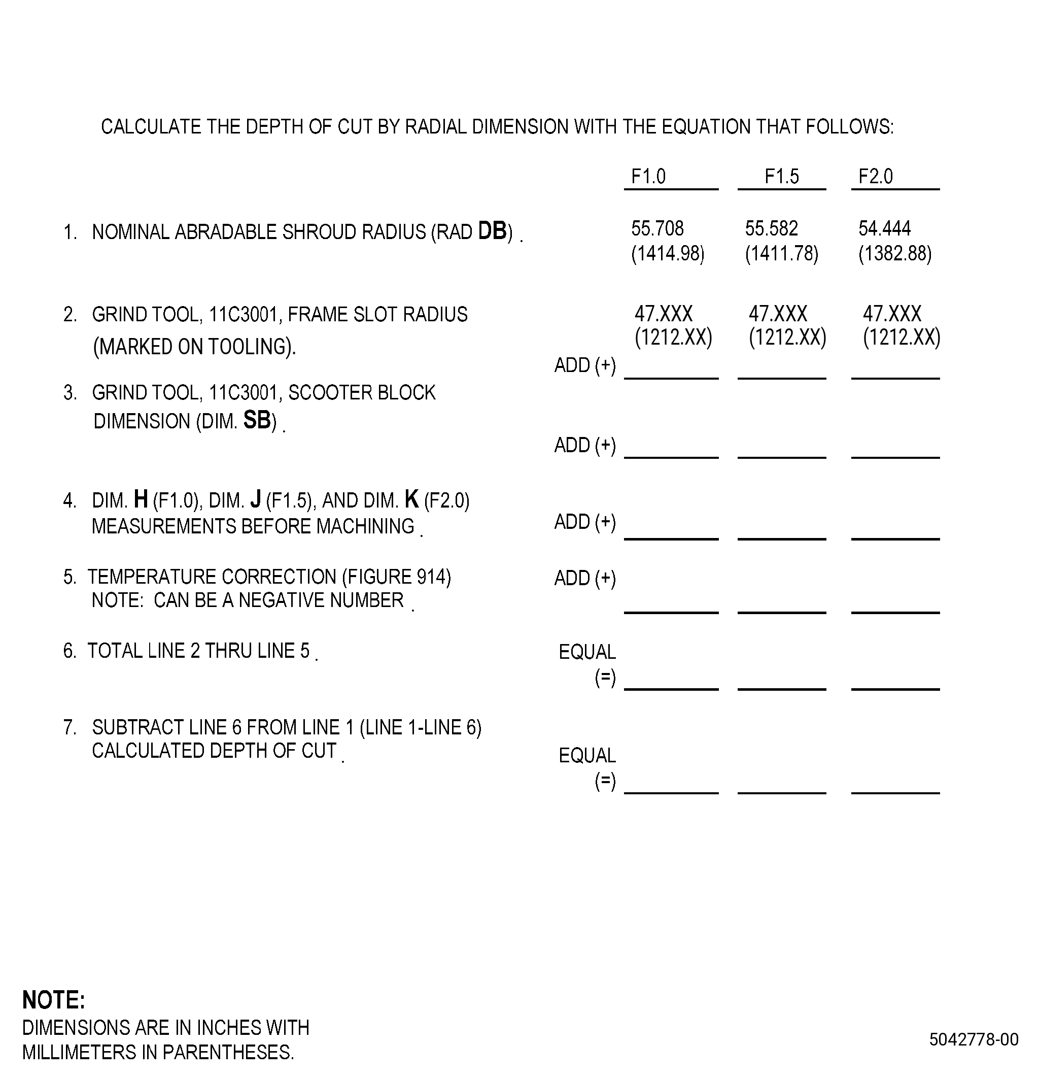
| (b) | Use the depth gauge to get dimension H, dimension J, and dimension K at the 6:00 o'clock position. Refer to Figure 904, Figure 916, and do as follows: |
| 1 | Record the measurements in the table. |
| (c) | Use the table in Figure 916 to calculate the radius at the 6:00 o’clock position as follows: |
| 1 | Add dimension SB to the dimension H, dimension J, and dimension K that you measured. |
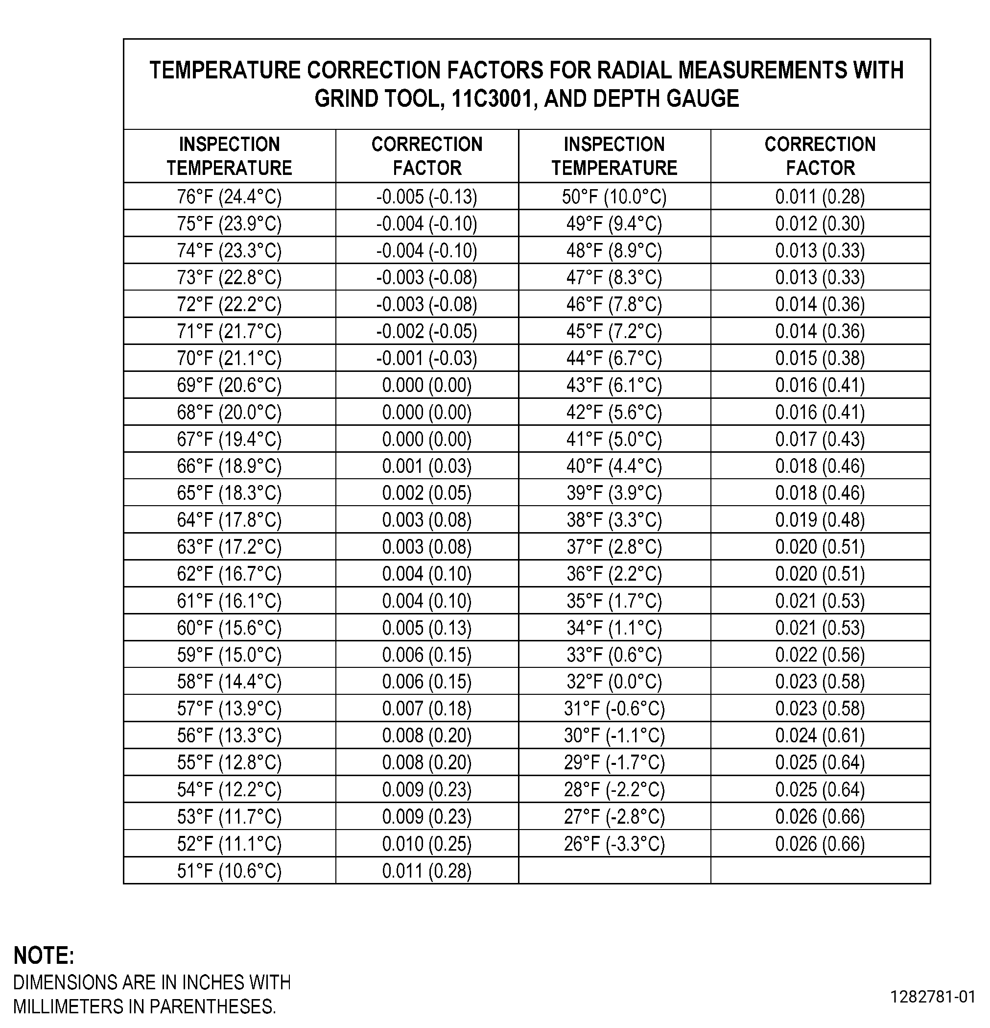
| 2 | Add the temperature correction factor for the 11C3001 grind tool. Refer to Figure 914. |
| NOTE: |
|
| (d) | Subtract the calculated abradable shroud radius from the nominal case radius for the F1.0 location, F1.5 location, and F2.0 location. The difference is the nominal depth of cut at the 6:00 o’clock position. |
| Subtask 72-00-01-360-016 |
| (e) | If the calculated depth of cut at the 6:00 o’clock position is negative, do Subtask 72-00-01-350-066 (paragraph 5.P.) thru Subtask 72-00-01-360-014 (paragraph 5.W.) again to add more C01-161 abradable material. |
| Subtask 72-00-01-320-004 |
| (2) | Machine the abradable shroud contour. Refer to Subtask 72-00-01-320-001 (paragraph 5.Z.(3)) thru Subtask 72-00-01-320-001 (paragraph 5.Z.(9)(j)2c), and as follows: |
| (a) | Use the calculated depth of cut. Refer to Figure 916. |
| NOTE: |
|
| Subtask 72-00-01-160-011 |
| AA. | Clean the repair area as follows: |
| (1) | Alternative Procedure Available. Remove the dust and debris with a dustpan and a C10-108 brush. |
| Subtask 72-00-01-160-013 |
| (1).A. | Alternative Procedure. Remove all the abradable dust and debris with a vacuum cleaner. |
| WARNING: |
|
| (2) | Remove the remaining dust from the repair area with compressed air that contains no oil. |
| Subtask 72-00-01-220-114 |
| AB. | Do an inspection of the abradable shroud repair area for voids and missing C01-161 abradable material. Refer to TASK 72-00-01-200-801 (72-00-01, INSPECTION 001), and as follows: |
| (1) | Areas with a shore D hardness less than 50 are not permitted. |
| (2) | Do an inspection of the abradable surface. The defects that follow are permitted: |
| (a) | Three voids each 30 inches (762 mm) of circumference are permitted as follows: |
| 1 | If the voids are no more than 0.10 inch (2.5 mm) at the maximum dimension. |
| 2 | If the voids are no more than 0.060 inch (1.52 mm) in depth. |
| (b) | Any number of voids each 30 inches (762 mm) of circumference are permitted as follows: |
| 1 | If the voids are no more than 0.06 inch (1.5 mm) at the maximum dimension. |
| 2 | If the voids are no more than 0.03 (0.7 mm) in depth. |
| 3 | The total cumulative area of the voids must not be more than 20 square inches (129 square cm). |
| (c) | All voids less than 0.03 inch (0.7 mm) at the maximum dimension are permitted. |
| (d) | Forward facing steps with a maximum dimension of 0.02 inch (0.5 mm) are permitted. |
| (e) | Aft facing or axial steps with a maximum dimension of 0.04 inch (1.0 mm) are permitted. |
| (3) | Loose material and foreign material are not permitted. |
| (4) | Cracks and unbonded areas are not permitted. |
| Subtask 72-00-01-350-074 |
| (5) | If the inspection does not agree with the specified limits, do as follows: |
| (a) | For non-permitted defects with a minimum length/width/depth of 0.10 inch (2.6 mm), do Subtask 72-00-01-350-064 (paragraph 5.P.) thru Subtask 72-00-01-360-014 (paragraph 5.W.) again to fill the defects. |
| Subtask 72-00-01-350-274 |
| (b) | Alternative Procedure Available. If necessary, do Subtask 72-00-01-350-064 (paragraph 5.P.) thru Subtask 72-00-01-360-014 (paragraph 5.W.) again to fill non-permitted defects with a maximum length/width/depth of 0.10 (2.5 mm). |
| Subtask 72-00-01-350-275 |
| WARNING: |
|
| WARNING: |
|
| CAUTION: |
|
| (b).A. | Alternative Procedure. If necessary, fill the non-permitted defects not more than 0.10 (2.5 mm) at the maximum dimension. Refer to Figure 905 and do as follows: |
| 1 | Prepare the C01-155 adhesive paste as follows: |
| a | Make an estimate of the quantity of the C01-155 adhesive paste that you will use. |
| 2 | Use a clean metal or paper container that has no wax. |
| 3 | Mix each component in the ratio that follows: |
| a | Part A (adhesive) - 100 parts by weight. |
| b | Part B (catalyst) - 17 parts by weight. |
| 4 | Mix the two C01-155 adhesive paste components until you cannot see streaks of the components. |
| NOTE: |
|
| 5 | Use the spatula to push the C01-155 adhesive paste in the defects that you will repair. |
| 6 | Use a C10-182 cleaning cloth to remove the unwanted C01-155 adhesive paste. |
| 7 | Cure the C01-155 adhesive paste. Refer to SAE ARP 5144, Heat Application for Thermosetting Resin Curing, and as follows: |
| a | Let the mixed C01-155 adhesive paste cure for 8 hours at a minimum temperature of 65°F (18.4°C) followed by a minimum of 1 hour at a temperature range of 180 to 200°F (82.3 to 93.3°C). |
| Subtask 72-00-01-140-013 |
| WARNING: |
|
| (c) | Sand the abradable shroud with C10-141 abrasive paper to make the repair area smooth and agree with the adjacent contour. |
| Subtask 72-00-01-220-115 |
| AC. | Do the measurements for the fan blade tip clearances and the abradable shroud runout as follows: |
| NOTE: |
|
| NOTE: |
|
| (1) | Alternative Procedure Available. If you use the 11C3001 grind tool, to get the runout measurements, do as follows: |
| (a) | Do Subtask 72-00-01-350-065 (paragraph 5.K.) again to get the runout measurements for the F1.0 location, F1.5 location, and F2.0 location. |
| (b) | Record the runout measurements in Figure 912. |
| (c) | Remove the 11C3001 grind tool, from the fan disk. |
| (d) | Remove the masking from the fan disk and the outlet guide vanes. |
| (e) | Install the fan blades, the fan platforms, and the aft support spinner ring. Refer to TASK 72-00-01-420-801 (72-00-01, INSTALLATION 001, CONFIG 01). |
| (f) | Do Subtask 72-00-01-220-109 (paragraph 5.E.) to get the clearances at the F1.0 location, F1.5 location, and F2.0 location. |
| (g) | Record the clearance measurements. Refer to Figure 913. |
| Subtask 72-00-01-220-117 |
| (1).A. | Alternative Procedure. If you use the 11C3406 runout tool, to get the abradable shroud runout measurements, do as follows: |
| (a) | Remove the 11C3001 grind tool, from the fan disk. |
| (b) | Remove the masking from the fan disk and outlet guide vanes. |
| (c) | Install the fan blades, fan platforms, and aft support spinner ring. Refer to TASK 72-00-01-420-801 (72-00-01, INSTALLATION 001, CONFIG 01). |
| (d) | Do Subtask 72-00-01-220-109 (paragraph 5.E.) again to get the runout measurements and the clearance measurements at the F1.0 location, F1.5 location, and F2.0 location. |
| Subtask 72-00-01-220-118 |
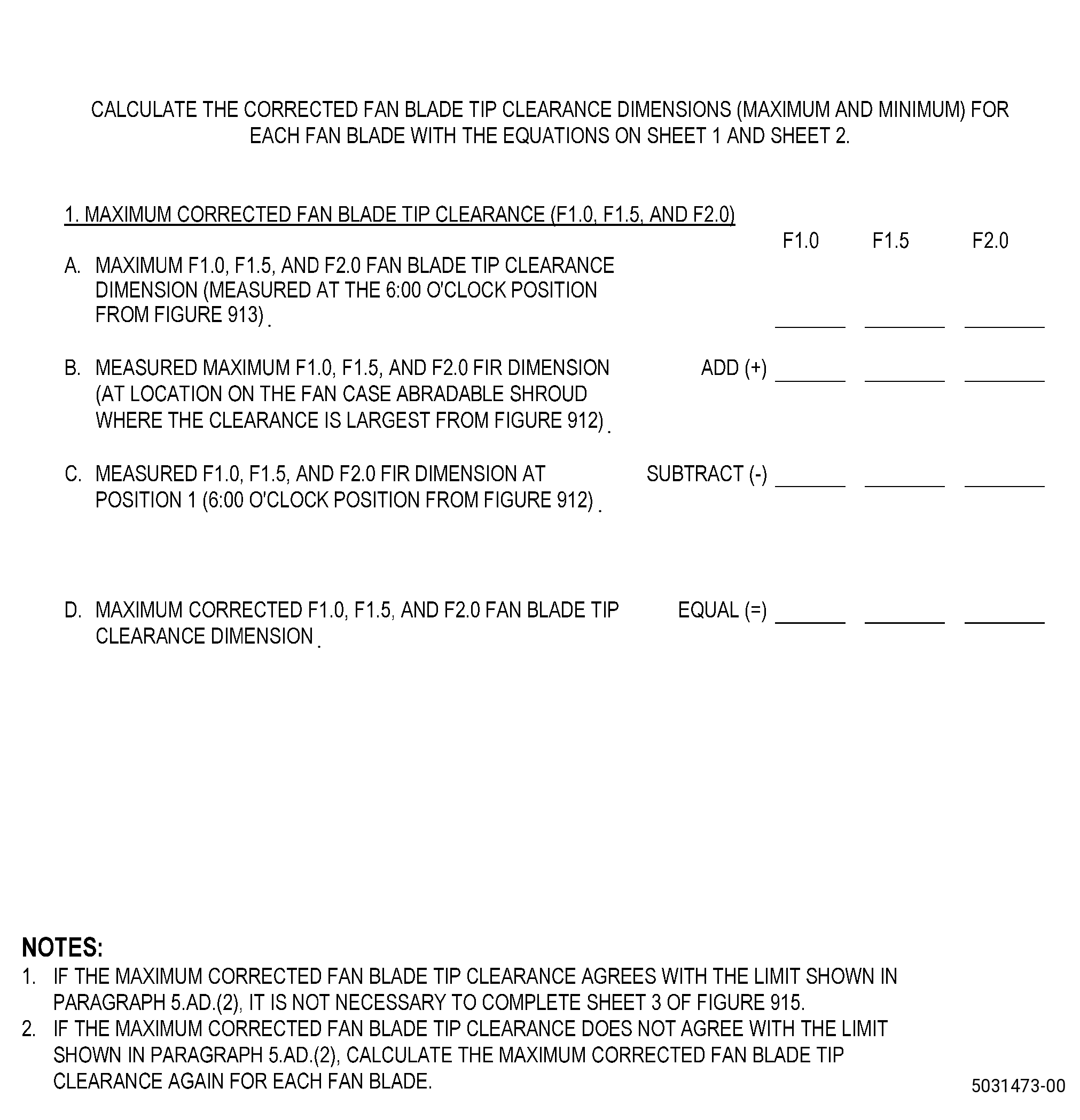
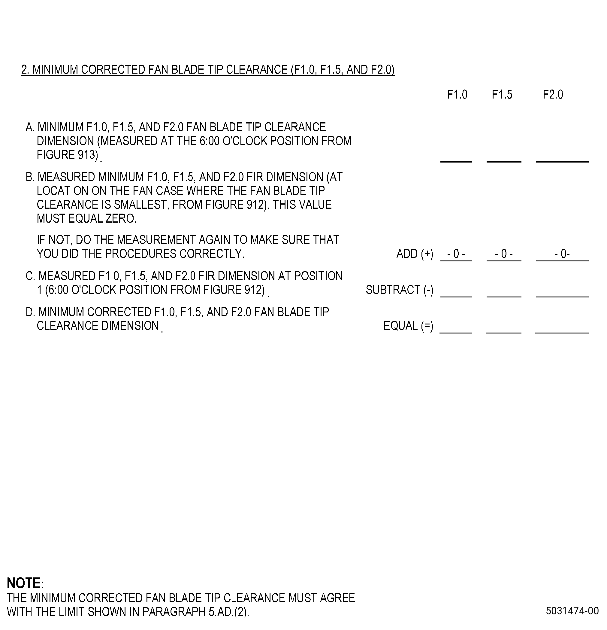
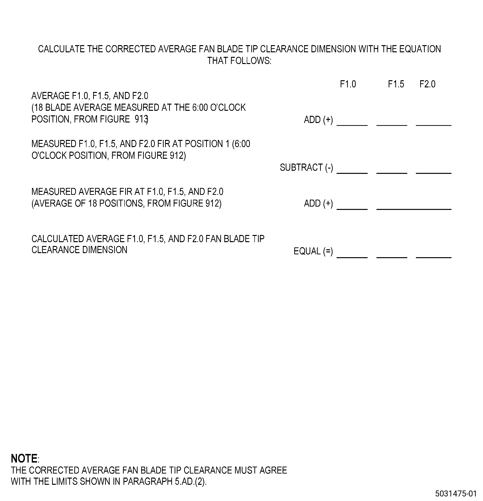
| AD. | Calculate the corrected fan blade tip clearances (minimum single blade, maximum single blade, and corrected average) for each of the 18 fan blades at the F1.0 location, F1.5 location, and F2.0 location. Refer to Figure 915 and do as follows: |
| (1) | Use the data that you recorded in Figure 912 and Figure 913 to calculate the corrected fan blade tip clearance maximum and minimum dimensions at F1.0 location, F1.5 location, and F2.0 location. |
| (2) | The corrected average fan blade tip clearance dimensions must agree with the limits that follow: |
| (a) | F1.0 = 0.254-0.329 inch (6.46-8.35 mm) |
| (b) | F1.5 = 0.232-0.305 inch (5.90-7.74 mm) |
| (c) | F2.0 = 0.373-0.403 inch (9.48-10.23 mm) |
| (3) | The single fan blade tip clearance dimensions must agree with the limits that follow: |
| (a) | F1.0 = 0.220-0.363 inch (5.59-9.22mm) |
| (b) | F1.5 = 0.198-0.339 inch (5.03-8.61 mm) |
| (c) | F2.0 = 0.339-0.437 inch (8.61-11.09 mm) |
| (4) | If the fan blade tip clearances do not agree with the limits specified, do the repair procedure again. |