| GENX-1B ENGINE MANUAL | Dated: 12/29/2023 | |
| EM 72-00-01 , REMOVAL 001 | ||
| FAN STATOR MODULE ASSEMBLY - REMOVAL 001 | ||
| GENX-1B ENGINE MANUAL | Dated: 12/29/2023 | |
| EM 72-00-01 , REMOVAL 001 | ||
| FAN STATOR MODULE ASSEMBLY - REMOVAL 001 | ||
| * * * FOR ALL |
| TASK 72-00-01-020-801 |
| 1 . | General. |
| A. | This procedure gives instructions to remove the fan stator module assembly (fan stator module) from the engine. Refer to Figure 301. |
| • |
|
| • |
|
| • |
|
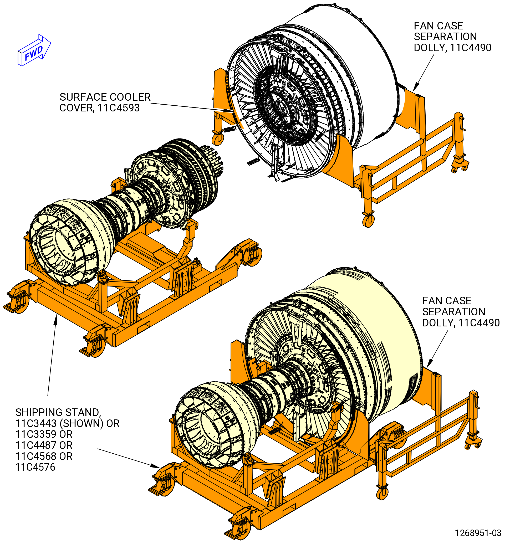
| B. | This procedure starts with the engine in the horizontal position on the 11C3443 shipping stand or 11C3359 shipping stand or 11C4487 shipping stand or 11C4568 shipping stand or 11C4576 shipping stand. As an alternative, you can install the engine in the 11C3281G01 turbine rear frame (TRF) pedestals and 11C3281G02 fan hub frame (FHF) pedestals . Refer to TASK 72-00-00-800-803 (72-00-00, SPECIAL PROCEDURE 003) . As an alternative, the engine can be installed in the 11C3044 adapter assembly, attached to the customer overhead rail system. Refer to Subtask 72-00-01-020-060 (paragraph 3.A.). |
| C. | Make sure that personnel read this procedure and know the step-by-step instruction and special tool usage before they remove the fan stator module. |
| D. | Make sure there is no foreign material in the engine or on engine parts. |
| 2 . | Tools, Equipment, and Materials. |
| NOTE: |
|
| A. | Tools and Equipment. |
| (1) | Special Tools. |
| (2) | Standard Tools and Equipment. None. |
| (3) | Locally Manufactured Tools. None. |
| B. | Consumable Materials. |
|
| C. | Referenced Procedures. |
|
| D. | Expendable Parts. None. |
| 3 . | Procedure. |
| Subtask 72-00-01-020-060 |
| A. | If customer overhead rail system is used, prepare the engine for installation with 11C3044 adapter assembly, 9429M44 support adapter, and 9429M47 support adapter as follows: |
| (1) | Remove the blank off panels to permit access of 11C3039 fan hub frame lift brackets. Refer to Subtask 72-00-01-020-005 (paragraph 3.G.). |
| (2) | Install the 11C3039 fan hub frame lift brackets. Refer to Subtask 72-00-01-490-002 (paragraph 3.N.). |
| (3) | Install the 9429M44 support adapter to the 11C3039 fan hub frame lift brackets. |
| (4) | Install the 9429M47 support adapter on the low pressure turbine (LPT) module. |
| (5) | Install the engine to the customer furnished overhead rail system with 11C3044 adapter assembly. |
| Subtask 72-00-01-020-001 |
| B. | If not installed, install the 11C3331 acoustic liner protector, on the forward mounting flange of the fan case stator module at the 6:00 o'clock position. Refer to Figure 301. |
| Subtask 72-00-01-020-044 |
| C. | If not installed, install the 11C4593 surface cooler cover. Refer to Figure 302. |
| Subtask 72-00-01-020-002 |
| D. | Remove the fan rotor spinner (83002) and aft support spinner ring (20-100 , 72-00-00) or spinner assembly aft support ring (aft support spinner ring) (20-101 , 72-00-00) as follows. Refer to Figure 303. |
| CAUTION: |
|
| (1) | Put the 11C4514 fan case protective mat in the lower half of the inlet cowl to protect the inlet cowl and engine. Refer to Figure 304. |
| (2) | Remove the fan rotor spinner as follows. Refer to Figure 303. |
| CAUTION: |
|
| (a) | Remove the 18 bolts (8302C) that attach the fan rotor spinner to the aft spinner ring. |
| CAUTION: |
|
| (b) | Remove the fan rotor spinner. |
| (c) | Put the fan rotor spinner in a protective cover. |
| (3) | Remove the aft support spinner ring as follows: |
| (a) | Remove the 18 bolts (20-110 , 72-00-00) that attach the aft spinner ring to the fan rotor disk. |
| (b) | Put the aft support spinner ring in a protective cover. |
| Subtask 72-00-01-020-003 |
| E. | Remove each of the stage 1 fan blades (fan blades) (20-200 , 72-00-00) (SIN 83004) or (20-201 , 72-00-00) (SIN 83004). Refer to Figure 306 and do as Follows: |
| (1) | Number the fan blades from No. 1 thru No. 18 as follows: |
| (a) | Find the No. 1 fan blade. |
| (b) | Use a C05-003 pen and mark No. 1 on the fan blade dovetail. |
| (c) | Continue to number the blades from No. 2 thru No. 18 in a counterclockwise (CCW) direction. |
| CAUTION: |
|
| CAUTION: |
|
| (2) | Turn the fan disk so that No. 1 blade is at the 6:00 o'clock position. |
| Subtask 72-00-01-020-057 |
| (3) | Alternative Procedure Available. Remove the fan platforms (20-120 , 72-00-00) (SIN 83005) or (20-121 , 72-00-00) (SIN 83005) as follows: |
| (a) | Prepare the 11C4645 blade spreading fixture for use. Refer to Figure 305 and do as follows: |
| 1 | Align the left foot (item 4) hole with the left support (item 13) hole that has the GENX-1B mark. |
| 2 | Put the ball lock pin (item 15) through the two holes. |
| CAUTION: |
|
| (b) | Apply C10-021 tape from the fan blade side to the top of each fan platform (20-120 , 72-00-00) (SIN 83005) or (20-121 , 72-00-00) (SIN 83005) to make sure that the platform does not fall. |
| WARNING: |
|
| (c) | Carefully lift the 11C4645 blade spreading fixture with the handle (item 14) and put it between the fan blades with the base (item 10) on the inside surface of the fan case. |
| (d) | Use the left hand to pull the arm (item 8) down with the lever arm (item 20) while putting the right hand on the base (item 10) to balance the 11C4645 blade spreading fixture. |
| NOTE: |
|
| (e) | Pull the arm (item 8) until the mark OPEN in the wedge (item 7) can be seen. |
| (f) | Carefully pull the fan platform straight down. Make sure not to scratch the adjacent fan blades. |
| (g) | Pull the arm (item 8) up with the lever arm (item 20) until the left foot (item 4) and right foot (item 5) are fully contracted in order to put the fan blades back into the initial position. |
| (h) | Use the handle (item 14) to lift and remove the 11C4645 blade spreading fixture. |
| (i) | Manually turn the fan rotor disk and continue to remove the fan platforms from the 6:00 o'clock position. |
| (j) | Keep each fan platform together with the machine bolt (bolt) (20-150 , 72-00-00) (SIN 8302A), stage 1 fan blade spacer (spacer) (20-170 , 72-00-00) (SIN 83008), dovetail key (20-180 , 72-00-00) (SIN 8300B), and stage 1 retainer (retainer) (20-190 , 72-00-00) (SIN 83007) that were removed from each blade. Refer to Figure 306. |
| Subtask 72-00-01-020-058 |
| (3).A. | Alternative Procedure. Remove the fan platforms (20-120 , 72-00-00) (SIN 83005) or (20-121 , 72-00-00) (SIN 83005) as follows: |
| NOTE: |
|
| CAUTION: |
|
| (a) | Apply C10-021 tape from the fan blade side to the top of each fan platform (20-120 , 72-00-00) (SIN 83005) or (20-121 , 72-00-00) (SIN 83005) to make sure that the platform does not fall. |
| (b) | Apply as much side force as possible to two fan blades at the 6:00 o'clock position without causing damage to them. |
| (c) | Have a second person move the fan platform back and forth and pull it down to remove it from between the fan blades. |
| (d) | Carefully pull the fan platform straight down. Make sure that you do not scratch the adjoining fan blades. |
| (e) | Manually turn the fan rotor disk and continue to remove the fan platforms from the 6:00 o'clock position. |
| (f) | Keep each fan platform together with the bolt (20-150 , 72-00-00) (SIN 8302A), spacer (20-170 , 72-00-00) (SIN 83008), dovetail key (20-180 , 72-00-00) (SIN 8300B), and retainer (20-190 , 72-00-00) (SIN 83007) that were removed from each blade. Refer to Figure 306. |
| Subtask 72-00-01-020-059 |
| (4) | Make sure that the No. 1 fan blade is at the 6:00 o'clock position. |
| Subtask 72-00-01-020-004 |
| (5) | Remove the fan blades (20-200 , 72-00-00) (SIN 83004) or (20-201 , 72-00-00) (SIN 83004) from the fan rotor disk (01-050 , 72-22-00) (SIN 830A0). Refer to Figure 306 and do as follows: |
| (a) | Start at the 6:00 o'clock position and remove the bolt (8302A) that attaches the spacer (83008) to the fan blade retainer (83007). |
| (b) | Remove the spacer, retainer, and dovetail key as follows. Refer to Figure 307. |
| 1 | Alternative Procedure Available. Remove the spacer with the 11C3398 slide hammer tool as follows: |
| NOTE: |
|
| a | Put the pin (item 4) in the spacer bolt hole. |
| b | Move the slide hammer (item 2) forward and aft to remove the spacer from the fan disk blade slot. |
| c | Remove the spacer from the slide hammer removal tool. |
| Subtask 72-00-01-020-042 |
| 1.A. | Alternative Procedure. Remove the spacer with the 11C3323 spacer removal tool, as follows: |
| a | Install the 11C3323 spacer removal tool as follows. Refer to Figure 307A. |
| b | Make sure that the hydraulic cylinder (item 7) is completely retracted. |
| c | Align the hydraulic cylinder (item 7) with the fan blade spacer and the fan disk. |
| d | Remove the dust cap (item 9) and connect a hydraulic hand pump to the female coupler (item 8). |
| e | Install the pin (item 5) in the hole of the fan blade spacer. |
| WARNING: |
|
| f | Apply hydraulic pressure to the hydraulic cylinder (item 7) to remove the fan blade spacer from the fan disk. |
| g | Remove the pin (item 5) from the spacer and remove the hydraulic cylinder. This tool will be used again to remove the remaining fan blade spacers (83007). |
| Subtask 72-00-01-020-043 |
| (c) | Remove the dovetail key (8300B). Refer to Figure 306. |
| (d) | Remove the fan blade retainer. |
| (e) | Remove the fan blade. Manually move the fan blade directly forward out of the dovetail slot. |
| (f) | Store the fan blades, spacers, dovetail keys, retainers, and bolts in the 11C4594 storage carrousel. Refer to Figure 308. |
| Subtask 72-00-01-020-038 |
| CAUTION: |
|
| (g) | Do Subtask 72-00-01-020-004 (paragraph 3.C.(5)(a)) thru Subtask 72-00-01-020-043 (paragraph 3.C.(5)(e)) to remove the remaining 17 fan blades (20-200 , 72-00-00) (SIN 83004) or (20-201 , 72-00-00) (SIN 83004). |
| Subtask 72-00-01-020-039 |
| (h) | After all 18 fan blades (20-200 , 72-00-00) (SIN 83004) or (20-201 , 72-00-00) (SIN 83004) are removed, remove the 18 shims (20-210 , 72-00-00) (SIN 83071) from the fan rotor disk posts. |
| Subtask 72-00-01-020-005 |
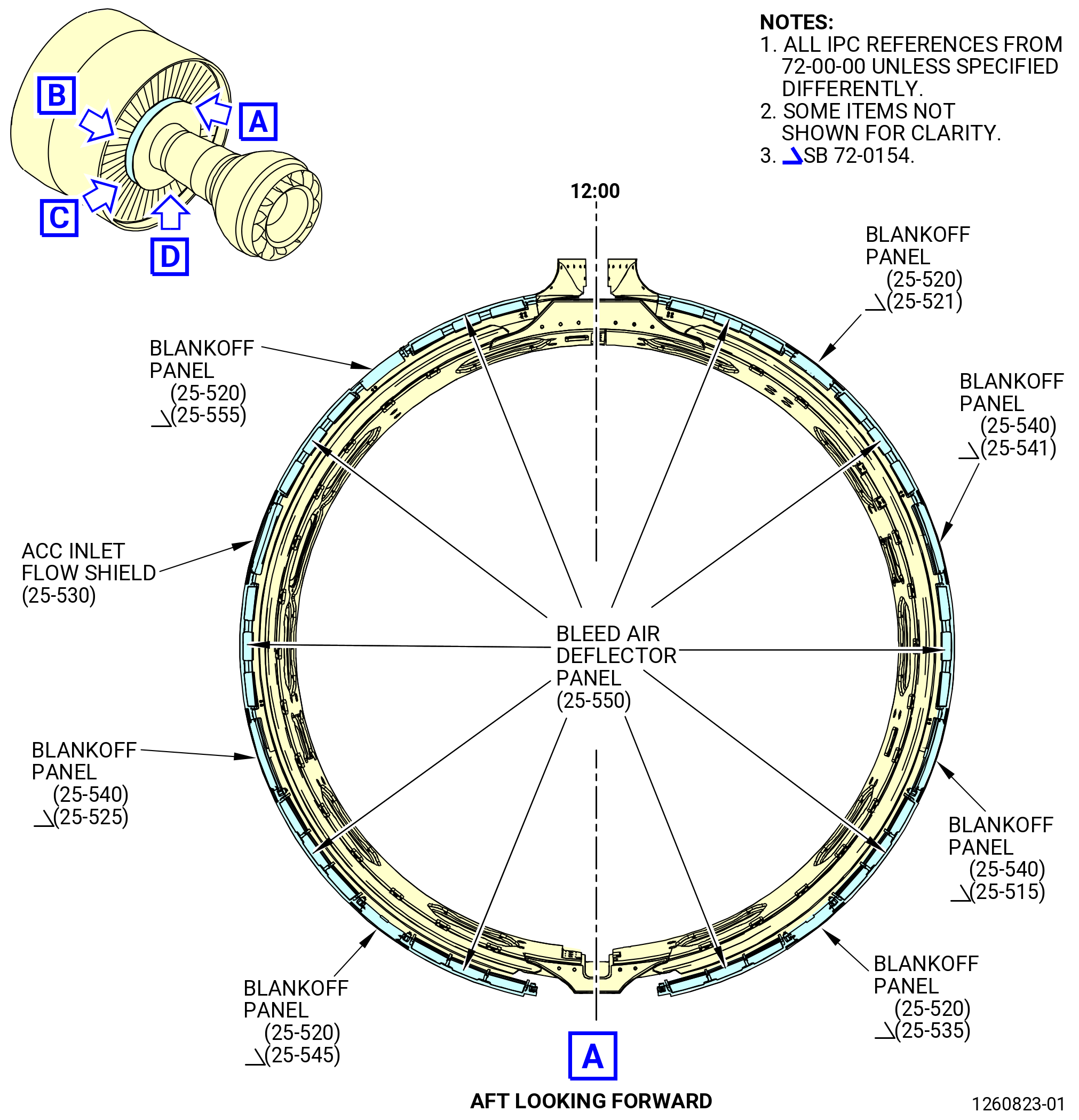
| F. | Remove the variable bypass valve (VBV) panels as follows. Refer to Figure 309. |
| (1) | Locate the ACC inlet flow shield at the 9:30 o'clock position (aft looking forward). Loosen the four screws and remove the ACC inlet flow shield. |
| (2) | Remove the remaining blankoff panels (25-520 , 72-00-00) (SIN 9500D) and (25-540 , 72-00-00) (SIN 9500B) or (25-541 , 72-00-00) (SIN 9500B), (25-515 , 72-00-00) (SIN 9500C), (25-521 , 72-00-00) (SIN 9500D), (25-525 , 72-00-00) (SIN 9500E), (25-535 , 72-00-00) (SIN 9500F), (25-545 , 72-00-00) (SIN 9500G), and (25-555 , 72-00-00) (SIN 9500H) (four on the right side, three on the left side) as follows: |
| (a) | Loosen the four machine screws (screws) (25-510 , 72-00-00) (SIN 95025) that attach each blankoff panel to the bleed air deflector panels (25-550 , 72-00-00) (SIN 9500A). |
| (b) | Slowly pull the blankoff panel aft out of the groove under the trailing edge of the outlet guide vanes. |
| (3) | Remove the ten bleed air deflector panels as follows: |
| (a) | Loosen the two screws (95025) in the center of the aft side of each bleed air deflector panel that attaches it to the deflector panel support segments. |
| (b) | At the 12:00 o'clock and 6:00 o'clock positions, bleed air deflector panels are installed underneath fillet fairings. Loosen the eight fairing screws that attach the four fillet fairings to the four bleed air deflector panels. |
| (c) | Slowly pull the bleed air deflector panel aft out of the groove under the trailing edge of the outlet guide vanes. |
| Subtask 72-00-01-020-006 |
| G. | Remove the lower bifurcation assembly. Refer to TASK 72-00-03-020-802 (72-00-03, REMOVAL 001). |
| Subtask 72-00-01-020-007 |
| H. | Remove the upper fillet fairings and upper bifurcation bridge (upper bridge) (25-170 , 72-00-00 or 25-171 , 72-00-00) as follows. Refer to Figure 310. |
| (1) | Remove the five bolts and the two bolts that attach the upper left fillet fairing to the left side of the upper firewall assembly. |
| (2) | Remove the upper left fillet fairing. |
| (3) | Remove the five bolts and the two bolts that attach the upper right fillet fairing to the right side of the upper firewall assembly. |
| (4) | Remove the upper right fillet fairing. |
| (5) | Remove the four bolts (25-150 , 72-00-00 or 25-151 , 72-00-00) and four washers that attach the upper bridge to the upper firewall assembly. |
| (6) | Remove the seven nuts and three washers that attach the upper bridge to the cowl supports (30-010 , 72-00-02) (SIN 95001) or (30-011 , 72-00-02) (SIN 95001) or (30-012 , 72-00-02) (SIN 95001) and (30-020 , 72-00-02) (SIN 95008) or (30-021 , 72-00-02) (SIN 95008) or 30-022 , 72-00-02) (SIN 95008) and control cables bridge bracket (bracket) (25-210 , 72-00-00) (SIN 68812) and fire suppression support bracket (bracket) (25-200 , 72-00-00) (SIN 9931A). |
| (7) | Remove the bracket (25-210 , 72-00-00) (SIN 68812) and bracket (25-200 , 72-00-00) (SIN 9931A). |
| (8) | Remove the upper bridge. |
| Subtask 72-00-01-020-008 |
| I. | Remove the lower fillet fairings and lower bifurcation bridge (lower bridge) (25-480 , 72-00-00 or 25-481 , 72-00-00) as follows. Refer to Figure 311. |
| (1) | Remove the five bolts and the two bolts that attach the lower left fillet fairing to the left side of the lower firewall assembly. |
| (2) | Remove the lower left fillet fairing. |
| (3) | Remove the five bolts and the two bolts that attach the lower right fillet fairing to the right side of the lower firewall assembly. |
| (4) | Remove the lower right fillet fairing. |
| (5) | Remove the four bolts (25-490 , 72-00-00 or 25-491 , 72-00-00) and four washers that attach the lower bridge to the upper firewall assembly. |
| (6) | Remove the four nuts and four washers that attach the lower bridge to the cowl supports (30-010 , 72-00-02) (SIN 95001) or (30-011 , 72-00-02) (SIN 95001) or (30-012 , 72-00-02) (SIN 95001) and (30-020 , 72-00-02) (SIN 95008) or (30-021 , 72-00-02) (SIN 95008) or (30-022 , 72-00-02) (SIN 95008). |
| (7) | Remove the lower bridge. |
|
|
|
|
| Subtask 72-00-01-490-001 |
| J. | Install the 11C4616 personnel stand in the fan stator module. Refer to Figure 312 and do as follows: |
| (1) | Install the support base (item 22) 4.0 inches (102 mm) from the forward flange of fan stator module to engage the support base (item 22) in the bottom side of the fan stator module. |
| WARNING: |
|
| (2) | Install the stand right base (item 23) by inserting three alignment pins from the block in the three holes located at the right side plates of the base support (item 22). |
| (3) | When the stand right base (item 23) is installed on the base support (item 22) and plates, lock the axial movement. |
| (4) | Install the stand left base (item 24) by inserting three alignment pins from the block in the three holes located at the left side plates of the base support (item 22). |
| (5) | When the stand left base (item 24) is installed on the base support (item 22) and plates, lock the axial movement. |
| (6) | To increase the height on the right side of the tool to an additional 12.0 inches (305 mm), install the right step (item 20) on the stand right base (item 23) by inserting two alignment pins into the corresponding holes on the stand right base (item 23). |
| (7) | Install the ball lock pin (item 7) between the right step (item 20) and stand right base (item 23) to attach both parts. |
| (8) | To increase the height on the left side of the tool to an additional 12.0 inches (305 mm), do Subtask 72-00-01-490-001 (paragraph 3.J.(6)) and Subtask 72-00-01-490-001 (paragraph 3.J.(7)) with the left step (item 21) on the stand left base (item 24). |
| (9) | Attach the two parts with the ball lock pin (item 7). |
| Subtask 72-00-01-020-009 |
| K. | Remove the acoustic linners (30-030 , 72-00-00) (SIN 84200) or (30-031 , 72-00-00) (SIN 84200) and the leading edge splitter (booster splitter) (30-050 , 72-00-00) (SIN 84202) or (30-051 , 72-00-00) (SIN 84202). Refer to Figure 313 and do as follows: |
| (1) | Begin with the acoustic liner that spans across the 12:00 o'clock position. |
| (2) | Remove the four screws (30-040 , 72-00-00) (SIN 84220) that attach the acoustic liner to the brackets (30-110 , 72-00-00) (SIN 83710). |
| (3) | Use your hand and carefully remove the acoustic liner. |
| (4) | Do Subtask 72-00-01-020-009 paragraphs 3.K.(1) thru 3.K.(3) for the five remaining acoustic liners. |
| (5) | Remove the 48 bolts (30-080 , 72-00-00) (SIN 837F0) that attach the booster splitter to the forward flange of the fan booster assembly. |
| Subtask 72-00-01-020-054 |
| * * * PRE SB 75-0013( Booster Anti-Ice Manifold without Improvement ) |
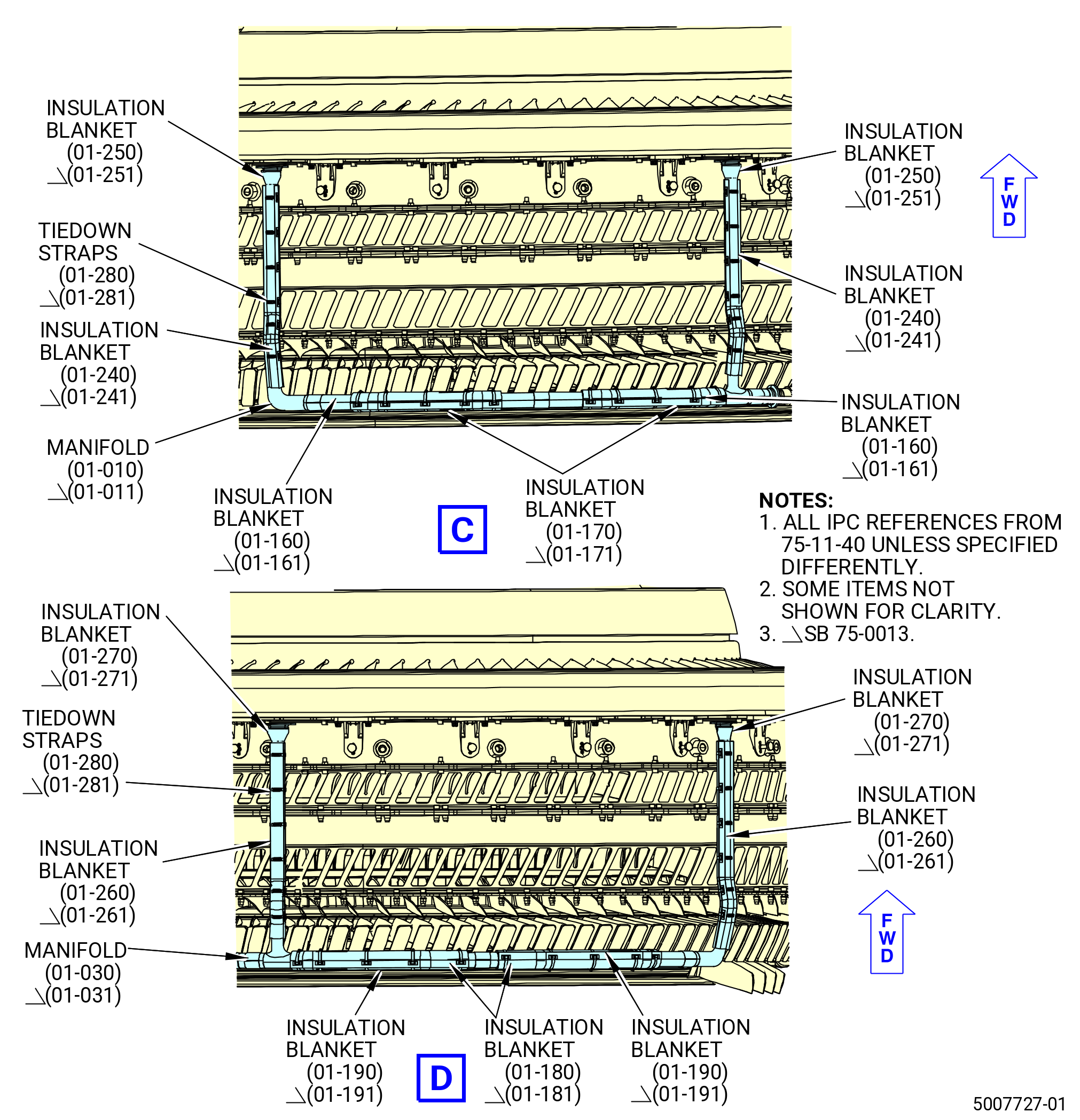
| (6) | Remove the 12 machine bolts (bolts) (01-110 , 75-11-40) (SIN 63721) that attach the manifolds (01-010 , 75-11-40) (SIN 63705), (01-020 , 75-11-40) (SIN 63706), and (01-030 , 75-11-40) (SIN 63707) to the tubes (30-090 , 72-00-00) (SIN 6370B) and fan booster splitter (30-050 , 72-00-00) (SIN 84202). Remove the tubes and seals (01-150 , 75-11-40) (SIN 63755). |
| * * * END PRE SB 75-0013 |
| Subtask 72-00-01-020-055 |
| * * * SB 75-0013( Booster Anti-Ice Manifold Improvement ) |
| (6).A. | Remove the 12 machine bolts (bolts) (01-111 , 75-11-40) (SIN 63721) that attach the manifolds (01-011 , 75-11-40) (SIN 63705), (01-021 , 75-11-40) (SIN 63706), and (01-031 , 75-11-40) (SIN 63707) to the booster splitter (30-051 , 72-00-00) (SIN 84202). |
| * * * END SB 75-0013 |
| Subtask 72-00-01-020-056 |
| (7) | Remove the booster splitter directly forward. |
| (8) | Remove the bolts (30-130 , 72-00-00) (SIN 83721) and washers (30-140 , 72-00-00) (SIN 83731) that attach the brackets (30-110 , 72-00-00) (SIN 83710) to the booster splitter (30-050 , 72-00-00) (SIN 84202) or (30-051 , 72-00-00) (SIN 84202). Remove the brackets. |
| (9) | Remove the 11 machine bolts (bolts) (01-130 , 75-11-40) (SIN 63720) that attach the manifolds to the support brackets (01-040 , 75-11-40) (SIN 63713) and (01-060 , 75-11-40) (SIN 63714) on the fan booster assembly (20-010 , 72-00-02) (SIN 80000) or (20-011 , 72-00-02) (SIN 80000). |
| (10) | Remove the coupling clamp (01-090 , 75-11-40) (SIN 63781) that attaches the manifold (01-010 , 75-11-40) (SIN 63705) or (01-011 , 75-11-40) (SIN 63705) to the manifold (01-020 , 75-11-40) (SIN 63706) or (01-021 , 75-11-40) (SIN 63706). |
| (11) | Remove the coupling clamp (01-090 , 75-11-40) (SIN 63781) that attaches the manifold (01-020 , 75-11-40) (SIN 63706) or (01-021 , 75-11-40) (SIN 63706) to the manifold (01-030 , 75-11-40) (SIN 63707) or (01-031 , 75-11-40) (SIN 63707). |
| (12) | Remove the manifolds from the fan booster assembly. |
| (13) | Remove the tiedown straps and the insulation blankets from the manifolds. |
| Subtask 72-00-01-020-010 |
| L. | Disconnect the oil vent tube (vent hose) (01-090 , 79-22-30 or 01-091 , 79-22-30) and hose (vent hose) (01-150 , 79-22-30 or 01-150 , 79-22-30) as follows. Refer to Figure 314. |
| (1) | Locate the vent hose at the 12:00 o'clock position on the cowl support. |
| Subtask 72-00-01-020-045 |
| * * * PRE SB 79-0009( Oil Vent Hose Tube Attached with Nuts ) |
| (2) | Loosen the four nuts (01-140 , 79-22-30) (SIN 46041) and remove the four bolts (01-120 , 79-22-30) (SIN 46028) that attach the two ends of the vent hose together through the cowl support. |
| * * * END PRE SB 79-0009 |
| Subtask 72-00-01-020-046 |
| * * * SB 79-0009( Oil Vent Hose Tube Attached with Brackets ) |
| (2).A. | Loosen the four bolts (01-120 , 79-22-30) (SIN 46028) and remove the two brackets (01-145 , 79-22-30) (SIN 46014) that attach the two ends of the vent hose together through the cowl support. |
| * * * END SB 79-0009 |
| Subtask 72-00-01-020-047 |
| (3) | Move the two ends of the vent hose away from the cowl support (30-020 , 72-00-02) (SIN 95008) or (30-021 , 72-00-02) (SIN 95008) or (30-022 , 72-00-02) (SIN 95008). |
| (4) | Remove and discard the two gaskets (01-130 , 79-22-30) (SIN 46052). |
|
|
| Subtask 72-00-01-490-002 |
| M. | If necessary, install the 11C3039 fan hub frame lift bracketsas follows. Refer to Figure 315. |
| CAUTION: |
|
| (1) | Locate the left lift bracket (item 3) and right lift bracket (item 2) and the 14 cap bolts (item 4) that attach the brackets to the aft side of the fan hub frame. |
| NOTE: |
|
| (2) | Use two people and align the brackets against the aft side of the fan hub frame. |
| (3) | Remove the seven bolts and seven spacers from each side of the fan hub frame. Put the bolts and spacers in a clear plastic bag and attach the bag to the fan hub frame for later use. |
| (4) | It may be necessary to remove a bolt from a blankoff panel, in order to remove the bolts and spacers. If this is required, temporarily remove the bolt from the blankoff plate. Install the bolt again as soon as possible after the lifting brackets are installed. |
| (5) | Use two people and attach a lift bracket to each side of the fan hub frame with seven cap bolts (item 4). |
| Subtask 72-00-01-020-011 |
| N. | Prepare to separate the fan stator module from the propulsor as follows: |
| WARNING: |
|
| (1) | Remove the 11C4616 personnel stand from the fan stator module as follows. |
| (2) | Remove the three bolts that attach the 11C3331 acoustic liner protector to the forward flange of the fan stator module. Remove the 11C3331 acoustic liner protector and return it to storage. Refer to Figure 301. |
| (3) | Attach the 11C4490 fan case separation dolly to the fan stator case as follows. Refer to Figure 316. |
| (a) | Use the jacking caster legs of the 11C4490 fan case separation dolly to align the support bracket of the dolly with the fan stator case flanges. |
| (b) | Attach the left and right support brackets to the forward and aft flanges of the fan stator module. |
| Subtask 72-00-01-020-012 |
| O. | Remove the fan stator module from the propulsor as follows. |
| (1) | Adjust the 11C4490 fan case separation dolly to make sure that the engine does not move or cause injury or damage during removal. Refer to Figure 316. |
| (a) | Turn the jacking caster leg of the side frame forward wheels until the wheels do not touch the ground. |
| (b) | Turn the jacking caster leg of the side frame aft wheels until there is a gap between the aft adapter pads and the fan stator module. |
| (c) | Turn the jacking caster leg of the forward wheels until the wheels touch the ground and the aft adapter pads touch the fan stator module. |
| (d) | Adjust the jacking caster leg of the forward wheels one full turn to tighten the aft adapter pads. |
| (e) | Put the jacking caster legs into the locked position. |
| (2) | Remove the 192 bolts from the forward and aft flanges of the fan hub frame that attach it to the fan stator case. Refer to Figure 317. |
| (3) | Unlock the jacking caster legs of the 11C4490 fan case separation dolly. |
| CAUTION: |
|
| (4) | Slowly separate the fan stator module from the propulsor by pulling the fan stator module forward, or by pushing the propulsor aft. Refer to Figure 318. |
| Subtask 72-00-01-020-037 |
| P. | Install the 11C3084 fan disk bore protector, 11C4634 protector, and 11C3083 disk protector in the stage 1 fan disk. Refer to Figure 319 and do as follows: |
| (1) | Fold the 11C4634 protector and install it in the bore behind the last web of the stage 1 fan disk. Unfold the 11C4634 protector. |
| (2) | Fold the 11C3084 fan disk bore protector and install it in the bore of the stage 1 fan disk. Unfold the 11C3083 disk protector. |
| (3) | Push the cover (item 2) of the 11C3083 disk protector on the stage 1 fan disk and attach it with the bolts (item 5). |
| Subtask 72-00-01-040-072 |
| Q. | Remove the cross-tie brackets (25-010 , 71-00-02) (SIN 25015) and (25-020 , 71-00-02) (SIN 25016), turbine rear frame (TRF) lower bumper brackets (25-030 , 71-00-02) (SIN 25010) and (25-070 , 71-00-02) (SIN 25019), deflection limiter brackets (25-040 , 71-00-02) (SIN 25011) and (25-050 , 71-00-02) (SIN 25012), and lower bumper bracket (25-060 , 71-00-02) (SIN 25014) from the aft flange of the TRF (01-010 , 72-57-00) (SIN 940A0) or (01-011 , 72-57-00) (SIN 940A0) and put them in a large and clear plastic bag. |
| NOTE: |
|
| Subtask 72-00-01-040-042 |
| R. | To continue to disassemble the fan stator module. Refer to TASK 72-00-01-040-805 (72-00-01, DISASSEMBLY 001). |
| Subtask 72-00-01-020-040 |
| S. | If you do not continue to disassemble, then storage the fan stator module. |
| Subtask 72-00-01-420-116 |
| * * * FOR ALL.ALL |
| T. | If the fan stator module will be shipped separately, then install the fan stator module into the 11C3004 shipping stand as follows: |
| (1) | Before installing the fan stator module, the 11C3004 shipping stand must be in the configuration as follows: |
| (a) | Stand in the pallet vertical position with the pallet base in the B747 position. |
| (b) | The center support in the raised position. |
| (c) | The mounting plate rotated to the 12 o'clock position and secured by the rotation lock pin. Refer to Figure 320. |
| (2) | Make sure that the center support frame is in the maximum raised position and the holding valve is closed. |
| (3) | Rotate the fan mounting plate to the “LOAD” position and engage the locking pin. |
| (4) | Remove the mounting hardware from the storage container located on the center support frame. |
| (5) | Remove the OGV support ring from the storage location on the center support frame and set aside. |
| (6) | Bring the fan stator module to the 11C3004 shipping stand with the forward flange facing the stand as follows: |
| WARNING: |
|
| (a) | If the fan stator module is supported by an overhead hoist, pull the rotation lock pin out of the mounting plate lock plate to let rotation of the plate to align the mounting holes to the fan stator module. |
| (b) | If the fan stator module is supported by a fan transfer dolly, use the dolly's jacking legs to align the fan stator module to the mounting plate holes. |
| NOTE: |
|
| (7) | Install all the mounting hardware. Insert the bolts from the mounting plate side. Attach firmly the bolts in place with a flat washer, lock washer and nut. Tighten the nuts to 400 lb in (45.1 Nm). |
| CAUTION: |
|
| (8) | Install the OGV support ring. Align the top C/L mark at the 12 o'clock position. There are two hole patterns on the ring mounting surface. Each hole is marked either “1B” or “2B”. Only one bolt is necessary for each OGV support ring. |
| (9) | Remove the fan stator module support. Pull the rotation lock pin clear of the mounting plate and rotate the plate to the designated “SHIP” position. Install all the remaining hardware. |
| (10) | If necessary, install the cover. |
| (11) | Install four turnbuckle shipping braces between the OGV support ring and the center support frame. Tighten the turnbuckle shipping braces to push out against the OGV support ring. Refer to Figure 321 and Figure 322. |
| (12) | Lower the center support frame until upper ends of the shipping braces can be pinned. Shift the “C” valve to the “OFF” position to stop the center support frame descent. |
| (13) | Close the holding valve and shift the “C” valve to the “OFF” position. |
| (14) | The stand is now ready to be moved to a truck or rotated to the pallet horizontal position. |
| * * * FOR ALL.ALL |
| * * * FOR ALL.ALL |
| * * * FOR ALL.ALL |