| GENX-1B CLEANING,INSPECTION,AND REPAIR MANUAL | Dated: 04/30/2019 | |
| CIR 72-00-01 , REPAIR 003 | ||
| FAN STATOR MODULE ASSEMBLY - REPAIR - ABRADABLE SHROUD AND TRENCHFILLER FACESHEET REPAIR | ||
| GENX-1B CLEANING,INSPECTION,AND REPAIR MANUAL | Dated: 04/30/2019 | |
| CIR 72-00-01 , REPAIR 003 | ||
| FAN STATOR MODULE ASSEMBLY - REPAIR - ABRADABLE SHROUD AND TRENCHFILLER FACESHEET REPAIR | ||
| * * * FOR ALL |
| TASK 72-00-01-300-801 |
| 1 . | Abradable Shroud and Trenchfiller Facesheet Repair. |
| CAUTION: |
|
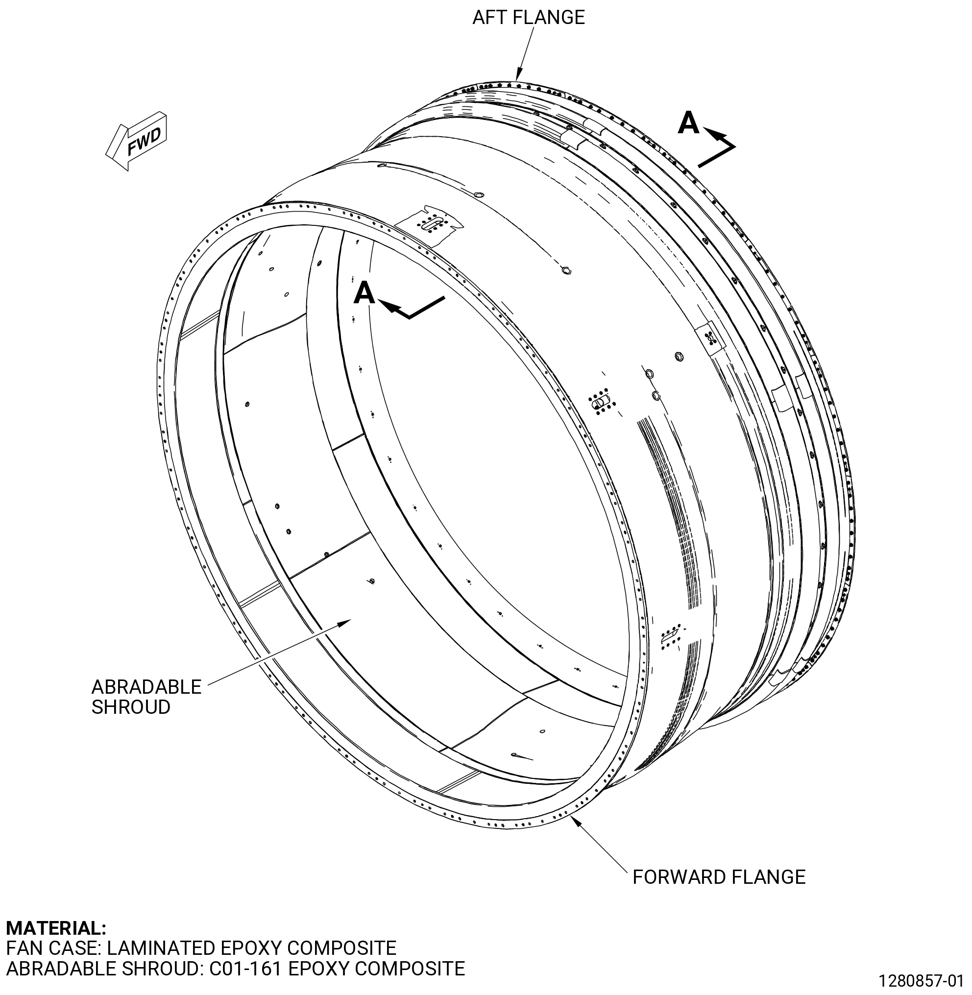
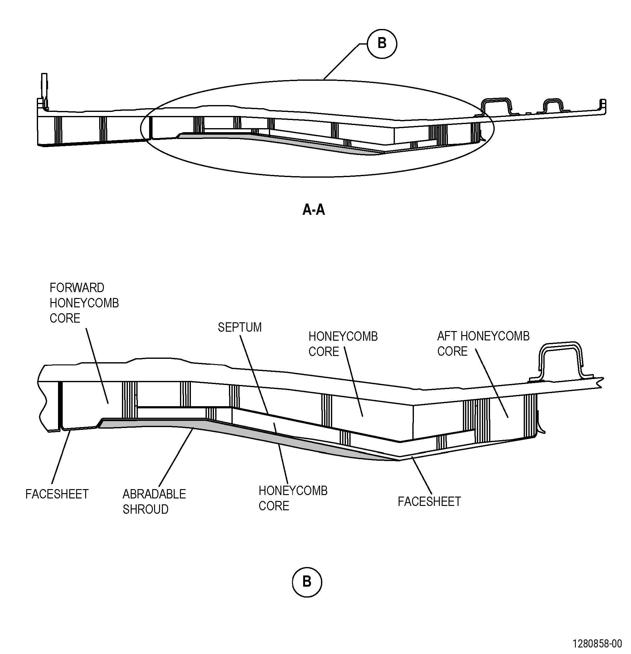
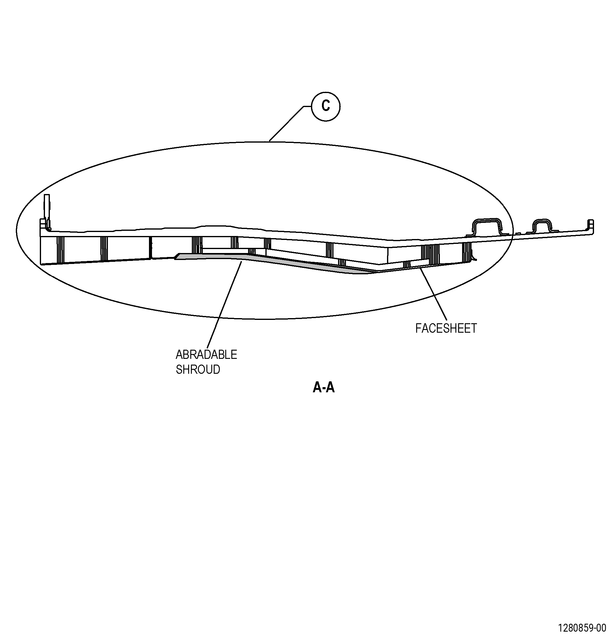
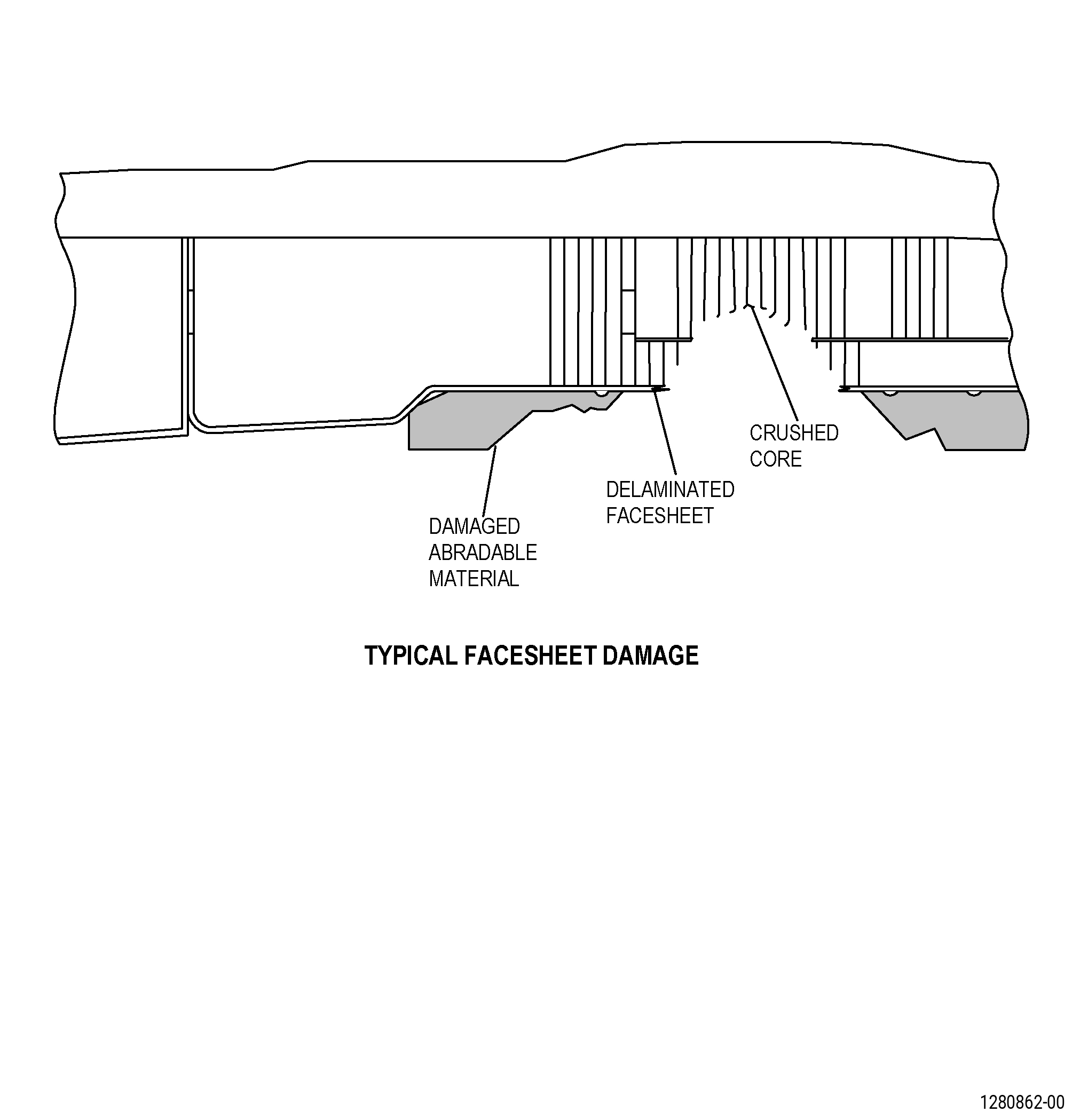
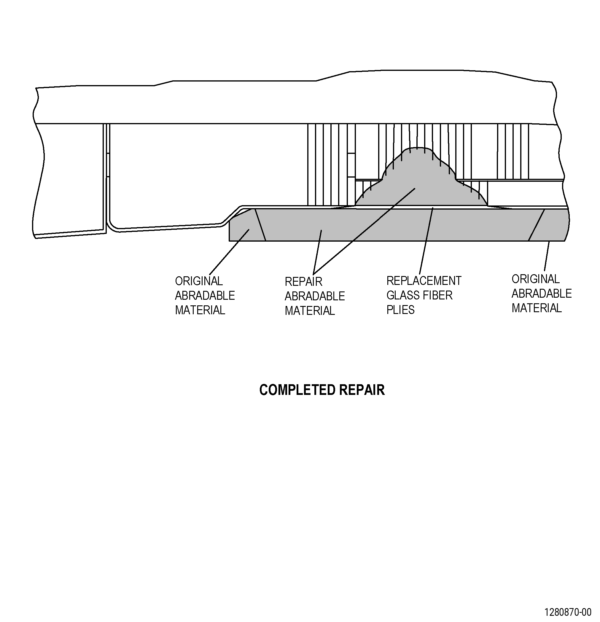
| A. | This procedure gives instructions to repair the fan stator module assembly (forward fan case) abradable shroud by applying a two part paste adhesive and, if necessary, by applying adhesive and glass cloth to the damaged facesheet. Refer to Figure 901. |
| B. | The following Maximum Repairable limits apply to this repair: |
| NOTE: |
|
| (4) | Visual Inspection |
| (a) | Do an inspection forward fan case (83500) for: |
| 4 | Voids wear grooves, rubs, and areas not bonded on the abradable material: |
| Maximum repairable limit: |
|
| 5 | Spalled, loose, or missing abradable material in the transition zones: |
| Maximum repairable limit: |
|
| 6 | Holes and punctures on the trenchfiller facesheet: |
| Maximum repairable limit: |
|
| NOTE: |
|
| (4) | Visual Inspection |
| (a) | Do an inspection of the containment case assembly (forward fan case) (83500). Refer to Figure 801 . |
| 4 | Voids wear grooves, rubs, and areas not bonded on the abradable material: |
| Maximum repairable limit: |
|
| 5 | Cracks in the eight trench filler panel joints and eight abradable panel joints |
| Maximum repairable limit: |
|
| 6 | Spalled, loose, or missing abradable material in the transition zones |
| Maximum repairable limit: |
|
| 7 | Holes and punctures in the trenchfiller facesheet |
| Maximum repairable limit: |
|
| NOTE: |
|
| (4) | Visual Inspection |
| (g) | Do an inspection of the abradable shroud for: |
| 1 | Voids wear grooves, rubs, and areas not bonded on the abradable material: |
| Maximum repairable limit: |
|
| 2 | Spalled, loose, or missing abradable material in the transition zones: |
| Maximum repairable limit: |
|
| 3 | Holes and punctures on the trenchfiller facesheet: |
| Maximum repairable limit: |
|
| (h) | Do an inspection of the eight trench filler panel joints and eight abradable panel joints for: |
| 1 | Cracks: |
| Maximum repairable limit: |
|
| C. | The subsequent table gives a list of the part numbers that are applicable to this repair. All part numbers are applicable to all paragraphs unless specified differently. |
| NOTE: |
|
| D. | Proprietary/Complex Process Statement. |
| (1) | None. |
| 2 . | Tools, Equipment, and Materials. |
| NOTE: |
|
| A. | Tools and Equipment. |
| (1) | Special Tools. None. |
| (2) | Standard Tools and Equipment. |
|
| (3) | Locally Manufactured Tools. |
|
| B. | Consumable Materials. |
|
| C. | Referenced Procedures. |
|
| D. | Expendable Parts. None. |
| E. | SPD Information. None. |
| F. | Special Solutions. None. |
| G. | Test Specimens. None. |
| 3 . | Dimensional Information. |
| Subtask 72-00-01-220-093 |
| A. | Refer to Figure 901 for specified dimensions and locations. |
| NOTE: |
|
| 4 . | Setup Information. |
| None. |
| 5 . | Procedure. |
| Subtask 72-00-01-350-001 |
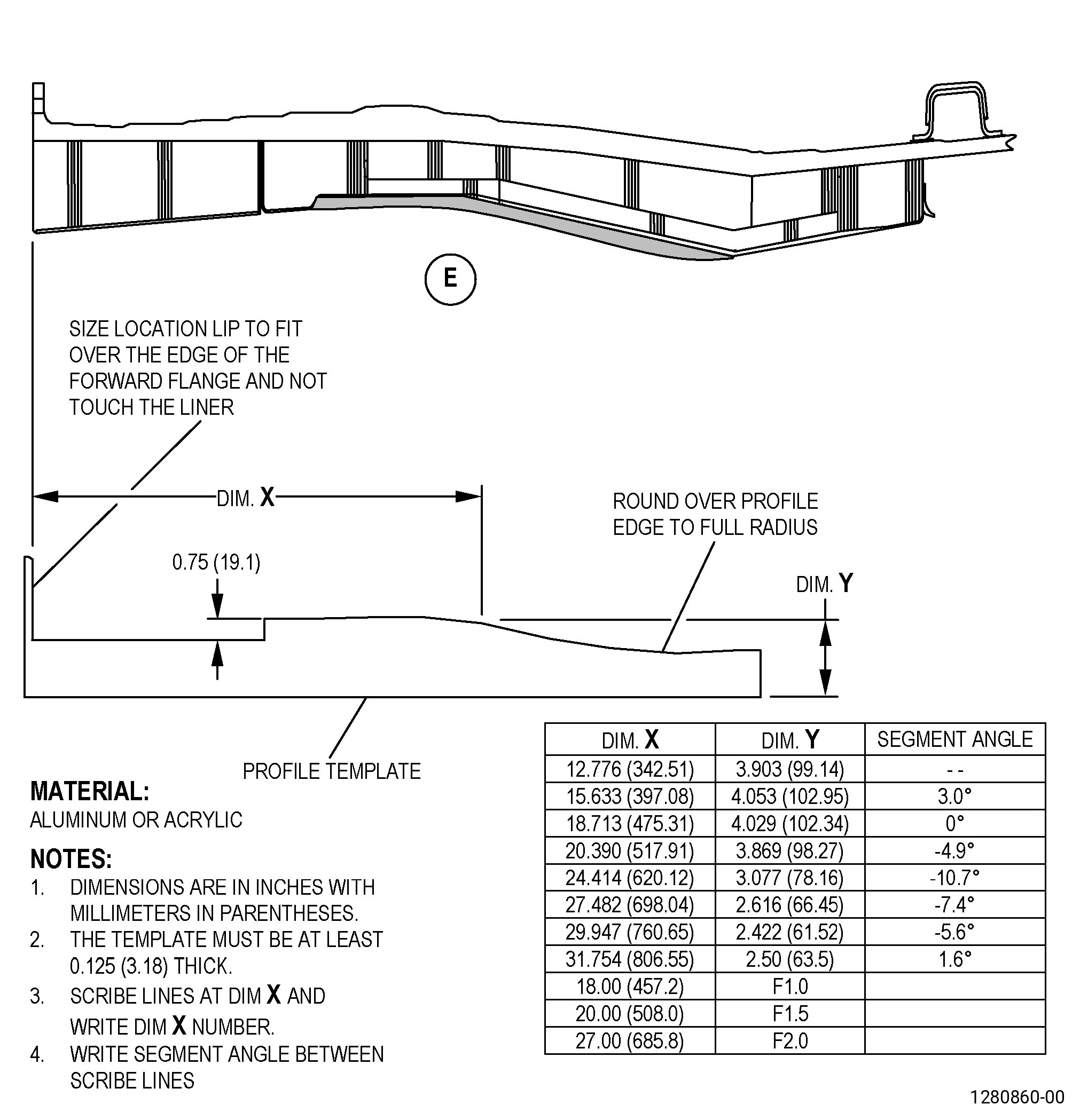
| A. | If necessary, make a profile template. Refer to Figure 902. |
| Subtask 72-00-01-350-002 |
| B. | Apply masking around the forward fan case abradable shroud repair area. Refer to TASK 70-46-01-350-030 (MASKING AND CLEANING OF EPOXY AND POLYESTER MATRIX THERMOSETTING COMPOSITE MATERIALS), and as follows: |
| (1) | Use Composite Masking Method No. 3. |
| Subtask 72-00-01-350-003 |
| WARNING: |
|
| C. | Prepare the forward fan case abradable shroud for repair as follows: |
| (1) | Remove all loose material from the abradable shroud repair area. Refer to Figure 903. |
| CAUTION: |
|
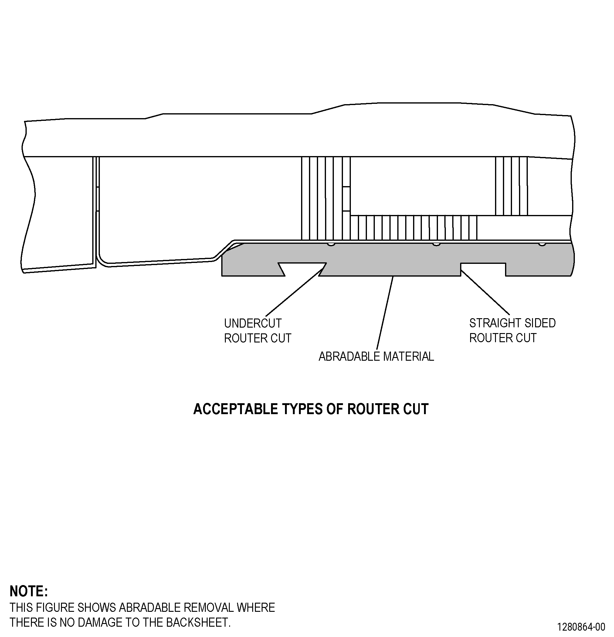
| (2) | Use a hand held router or a small belt sander to remove the damaged forward fan case abradable material. Refer to Figure 904 and as follows: |
| (a) | Remove the remaining damaged abradable material but do not remove the material that is correctly bonded to the glass fiber facesheet. |
| (b) | Make sure that the edges of the remaining abradable material have straight sides or a small undercut. Refer to Figure 904 and Figure 905. |
| Subtask 72-00-01-160-007 |
| (3) | Use a vacuum cleaner to remove all the unwanted material from the forward fan case abradable shroud repair area. |
| Subtask 72-00-01-220-106 |
| (4) | Look for oil contamination in the forward fan case abradable shroud area that you will repair and do as follows: |
| Subtask 72-00-01-140-009 |
| WARNING: |
|
| (a) | Sand the abradable shroud area to remove all the abradable material that has oil contamination as follows: |
| 1 | Use a hand held router or a small belt sander. |
| Subtask 72-00-01-220-094 |
| WARNING: |
|
| (5) | Do an inspection of the abradable shroud repair area for areas moist with water and do as follows: |
| (a) | Dry the abradable shroud repair area to remove liquids. Refer to TASK 70-46-02-360-002 (DRYING OF THERMOSETTING COMPOSITE MATERIALS), and as follows: |
| 1 | Use Absorbed Moisture Removal - Method 2 (Radiant Heater) or Absorbed Moisture Removal - Method 3 (Hot Air Dryer). |
| 2 | Attach a thermocouple to the moist area. |
| 3 | Use a hot air gun or heat lamp to dry the areas. Increase the temperature of the area to a maximum of 180°F (82°C). |
| 4 | Keep the area at a temperature of 180°F (82°C) until you cannot see the water. |
| 5 | Continue to dry the repair area for a minimum of 30 minutes more after you cannot see the water. |
| Subtask 72-00-01-220-095 |
| D. | If you can see the glass fiber facesheet, do an inspection of the glass fiber facesheet as follows: |
| (1) | Look for damage to the facesheet and do as follows: |
| (a) | Put a mark around the facesheet damaged area. Refer to TASK 70-16-00-350-001 (MARKING PRACTICES), TASK 70-16-02-350-017 (TEMPORARY MARKING), and as follows: |
| 1 | Use a C05-003 marking pen. |
| Subtask 72-00-01-930-004 |
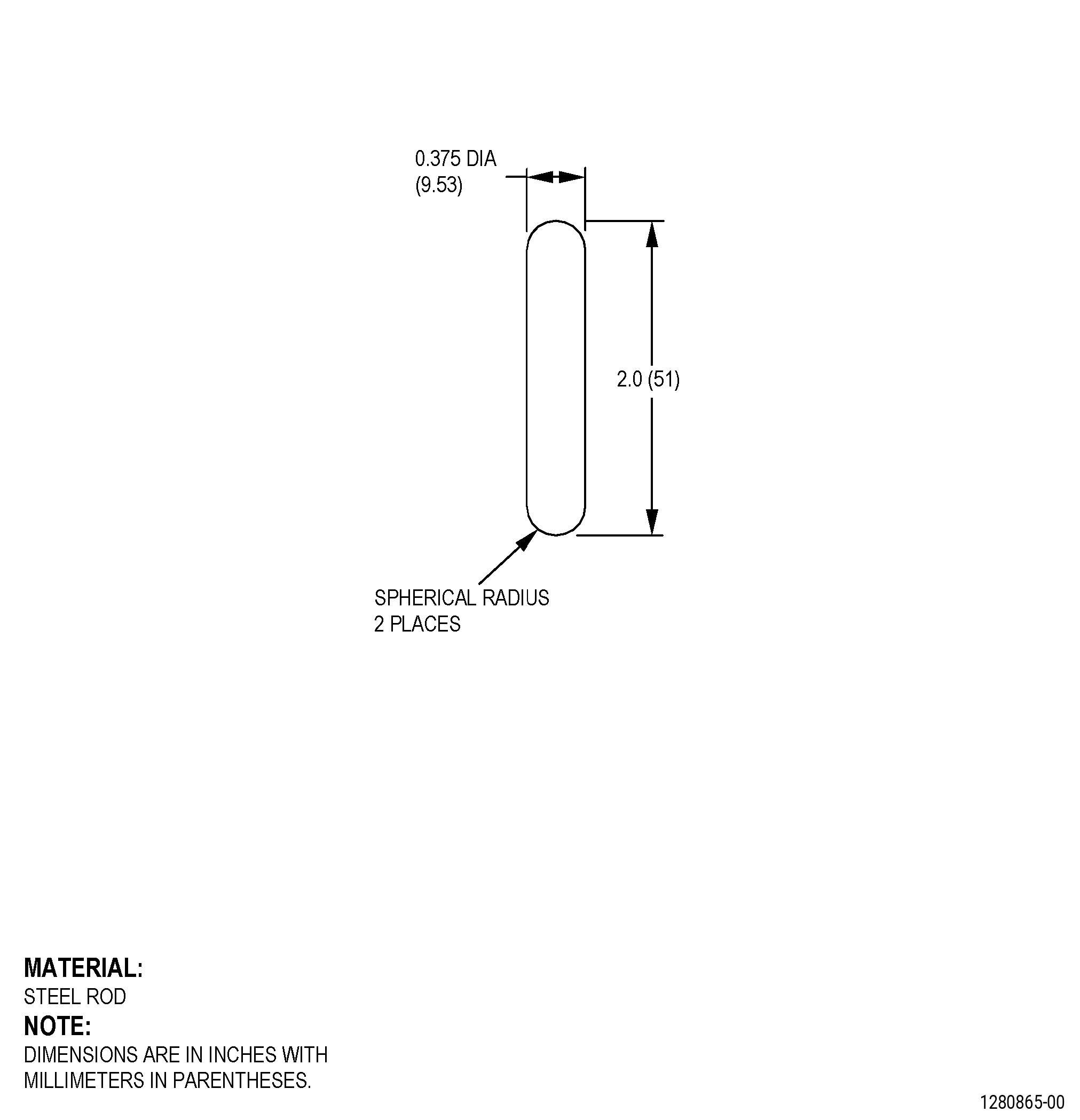
| (2) | If necessary, make a steel rod. Refer to Figure 906. |
| Subtask 72-00-01-350-051 |
| (3) | Tap the facesheet lightly with the steel rod. Listen to the sound and do as follows: |
| NOTE: |
|
| (a) | If you hear a solid click, there is no disbond or delamination. |
| (b) | If you do not hear a solid click, there is a disbond or delamination. |
| (4) | Put a large mark around the facesheet areas that are disbonded, delaminated or damaged. Refer to TASK 70-16-00-350-001 (MARKING PRACTICES), TASK 70-16-02-350-017 (TEMPORARY MARKING), and as follows: |
| (a) | Use a C05-003 marking pen. |
| (b) | The mark must be a shape that is easy to cut out. |
| Subtask 72-00-01-350-004 |
| E. | If there is no damage or disbonds in the facesheet, go to Subtask 72-00-01-140-004 (paragraph 5.AA.). If the damaged area is less than 150.00 sq in. (96774 sq mm), go to Subtask 72-00-01-350-005 (paragraph 5.F.). |
| NOTE: |
|
| Subtask 72-00-01-350-005 |
| WARNING: |
|
| WARNING: |
|
| F. | Cut and remove the damaged and disbonded facesheet material as follows: |
| (1) | Drill a hole of a minimum of 0.5 inch (13 mm) in diameter through the facesheet at each corner of the area that you identified in Subtask 72-00-01-220-095 (paragraph 5.D.(4)) to cut out, and as follows: |
| (a) | Do not drill deeper than necessary to drill through the facesheet. |
| (2) | Cut along the mark around the area that you will remove and as follows: |
| (a) | Use a small, right-angle drive grinder with a small cut-off disk. |
| (b) | Do not cut deeper than necessary to cut through the facesheet. |
| (3) | Start at a corner and carefully pull the damaged facesheet from the honeycomb. |
| Subtask 72-00-01-350-006 |
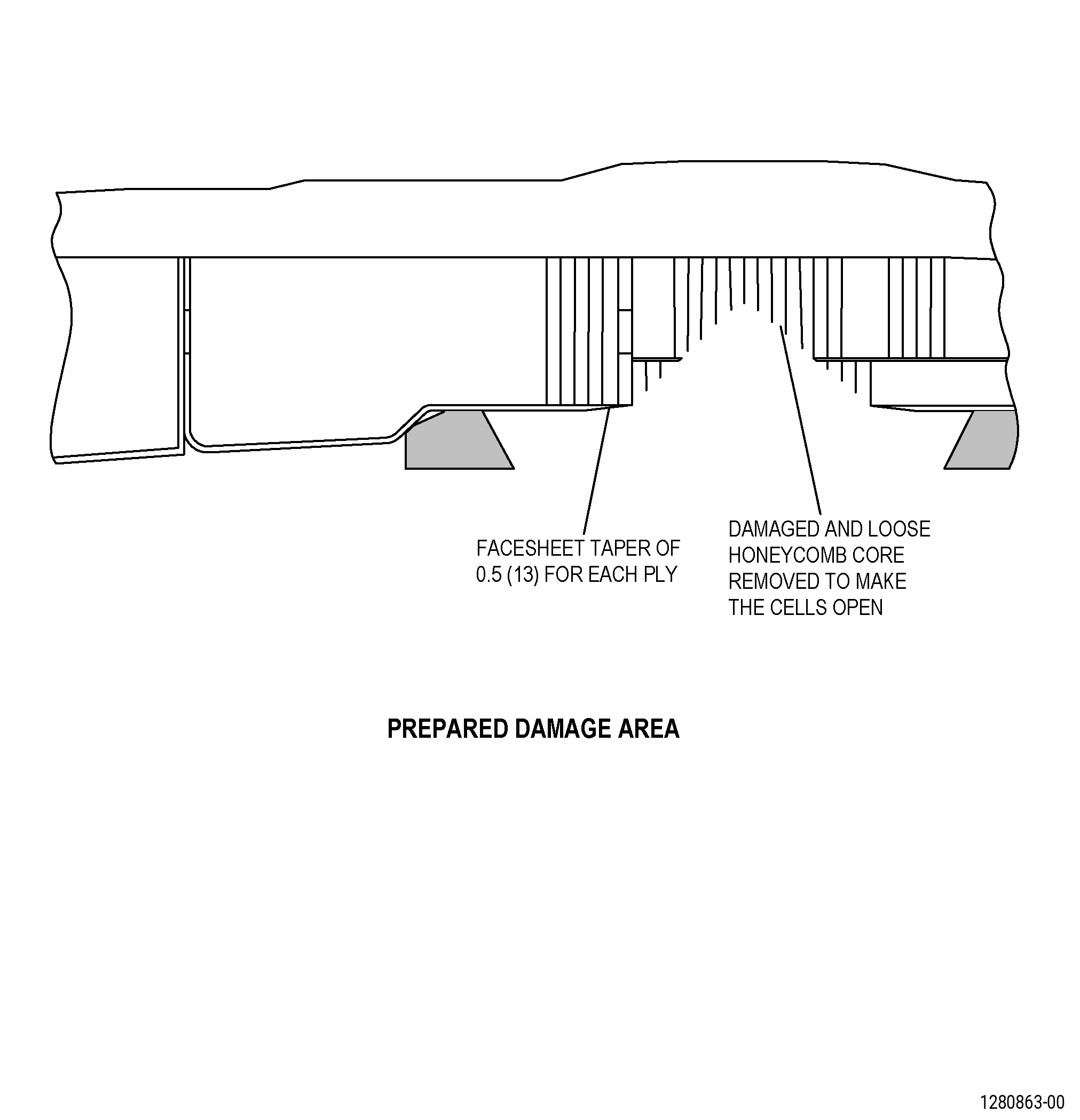
| G. | Remove the loose or damaged honeycomb. Refer to Figure 904 and as follows: |
| (1) | Remove the loose or damaged honeycomb until the top of the honeycomb cells are open. |
| (2) | If necessary, remove all the temporary patch material in the honeycomb cells. |
| NOTE: |
|
| Subtask 72-00-01-220-096 |
| H. | Do an inspection of the honeycomb cells and the facesheet in the forward fan case repair area as follows: |
| Subtask 72-00-01-360-005 |
| (1) | If necessary, dry the facesheet repair area to remove the liquids. Refer to TASK 70-46-02-360-002 (DRYING OF THERMOSETTING COMPOSITE MATERIALS), and as follows: |
| (a) | Use Visible Liquid Removal - Method 1 (water) or Visible Liquid Removal - Method 2 (liquid other than water). |
| (b) | After you remove the liquids, continue to dry the repair area as follows: |
| WARNING: |
|
| 1 | Use Absorbed Moisture Removal - Method 3 (Hot Air Dryer), and as follows: |
| a | Increase the temperature of the repair area to a maximum of 180°F (82°C). |
| b | Keep the repair area at 180°F (82°C) maximum until you cannot see the liquid. |
| c | Continue to dry the repair area for a minimum of 30 minutes more after you cannot see the liquid. |
| Subtask 72-00-01-350-052 |
| (2) | If there is oil contamination in the honeycomb cells, do as follows: |
| (a) | Clean the honeycomb cells. Refer to TASK 70-46-01-350-030 (MASKING AND CLEANING OF EPOXY AND POLYESTER MATRIX THERMOSETTING COMPOSITE MATERIALS), and as follows: |
| 1 | Use Honeycomb Cleaning Method 4. |
| WARNING: |
|
| 2 | Use C04-035 isopropyl alcohol. |
| (b) | Clean the honeycomb approximately 1.0 inch (25 mm) below the top of the cells. |
| (3) | If there is oil contamination on the facesheet repair area, do as follows: |
| Subtask 72-00-01-110-013 |
| (a) | Clean the forward fan case facesheet repair area. Refer to TASK 70-46-01-350-030 (MASKING AND CLEANING OF EPOXY AND POLYESTER MATRIX THERMOSETTING COMPOSITE MATERIALS), and as follows: |
| 1 | Use Composite Cleaning Method No. 4. |
| WARNING: |
|
| 2 | Use C04-035 isopropyl alcohol. |
| Subtask 72-00-01-140-001 |
| WARNING: |
|
| I. | Sand the forward fan case facesheet to make a taper in the glass fiber facesheet. Refer to Figure 904 and as follows: |
| (1) | Use a sanding disk of 1.0 inch (25 mm) in diameter in a small right angle drive grinder. |
| (2) | Make the taper 0.5 inch (13 mm) in width for each ply of the glass fiber cloth. |
| NOTE: |
|
| Subtask 72-00-01-140-002 |
| WARNING: |
|
| CAUTION: |
|
| J. | Prepare the surface of the remaining glass fiber facesheet as follows: |
| (1) | Sand manually the surface or use a belt sander until the surface has a constant matte finish. |
| NOTE: |
|
| (2) | Use C10-141 abrasive paper. |
| Subtask 72-00-01-110-014 |
| K. | Clean the forward fan case facesheet repair area. Refer to TASK 70-46-01-350-030 (MASKING AND CLEANING OF EPOXY AND POLYESTER MATRIX THERMOSETTING COMPOSITE MATERIALS), and as follows: |
| (1) | Use Composite Cleaning Method No. 5. |
| WARNING: |
|
| (2) | Use C04-035 isopropyl alcohol. |
| Subtask 72-00-01-350-007 |
| L. | Apply masking to the forward fan case facesheet repair area. Refer to TASK 70-46-01-350-030 (MASKING AND CLEANING OF EPOXY AND POLYESTER MATRIX THERMOSETTING COMPOSITE MATERIALS), and as follows: |
| (1) | Use Composite Masking Method No. 4. |
| (2) | Apply masking to the facesheet repair area until you apply the C01-161 abradable material. |
| Subtask 72-00-01-930-001 |
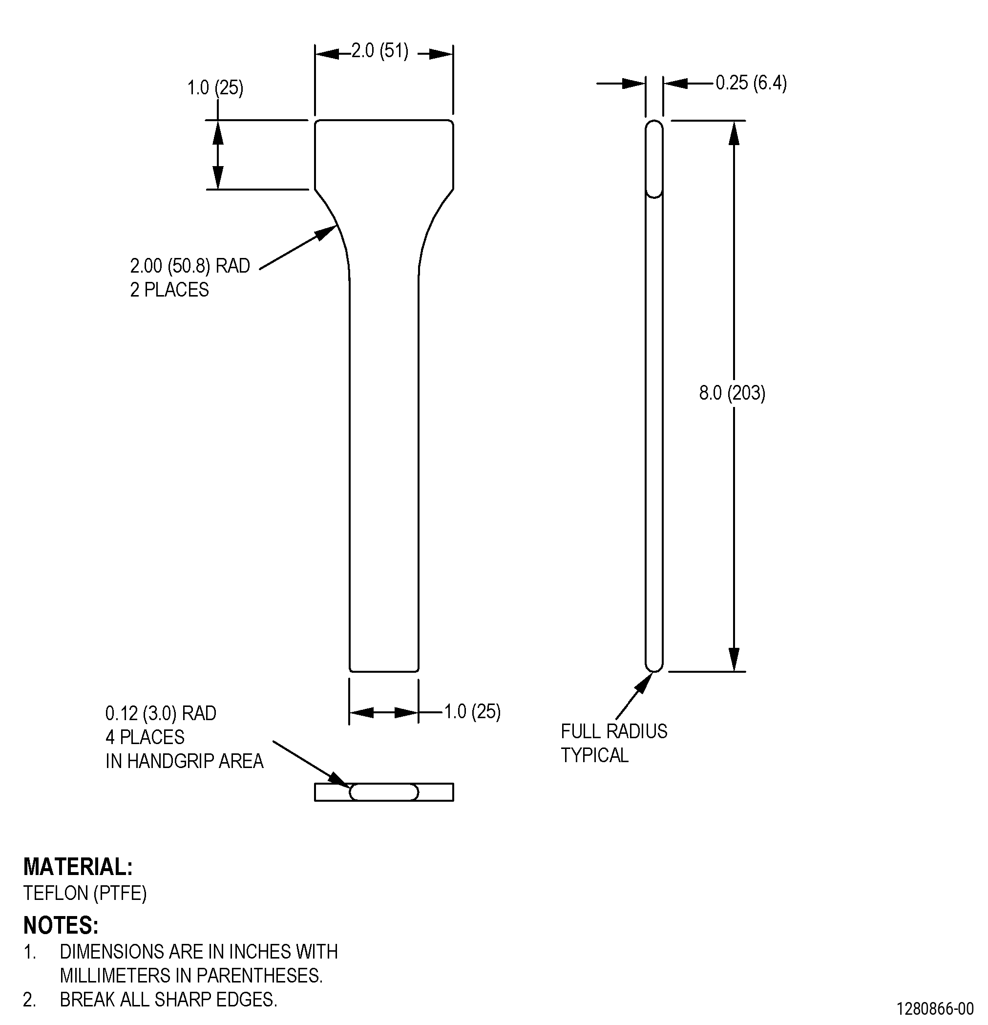
| M. | If necessary, make a Teflon spatula. Refer to Figure 907. |
| Subtask 72-00-01-350-008 |
| WARNING: |
|
| WARNING: |
|
| WARNING: |
|
| WARNING: |
|
| CAUTION: |
|
| N. | Mix the C01-161 abradable material as follows: |
| Subtask 72-00-01-350-053 |
| (1) | Alternative Procedure Available. Prepare the C01-161 abradable material packaged in the 1.5 lb (680 grams) [1 pint (473 milliliters)] kit as follows: |
| NOTE: |
|
| CAUTION: |
|
| (a) | Put the resin and hardener in a clean, grease- free metal plate. Keep the resin and hardener separate from each other. |
| (b) | Mix the resin and hardener separately with spatulas. Make sure that each part is fully mixed before you mix them together. |
| (c) | Mix the resin and hardener together until you see no streaks of the two components. |
| NOTE: |
|
| NOTE: |
|
| Subtask 72-00-01-350-009 |
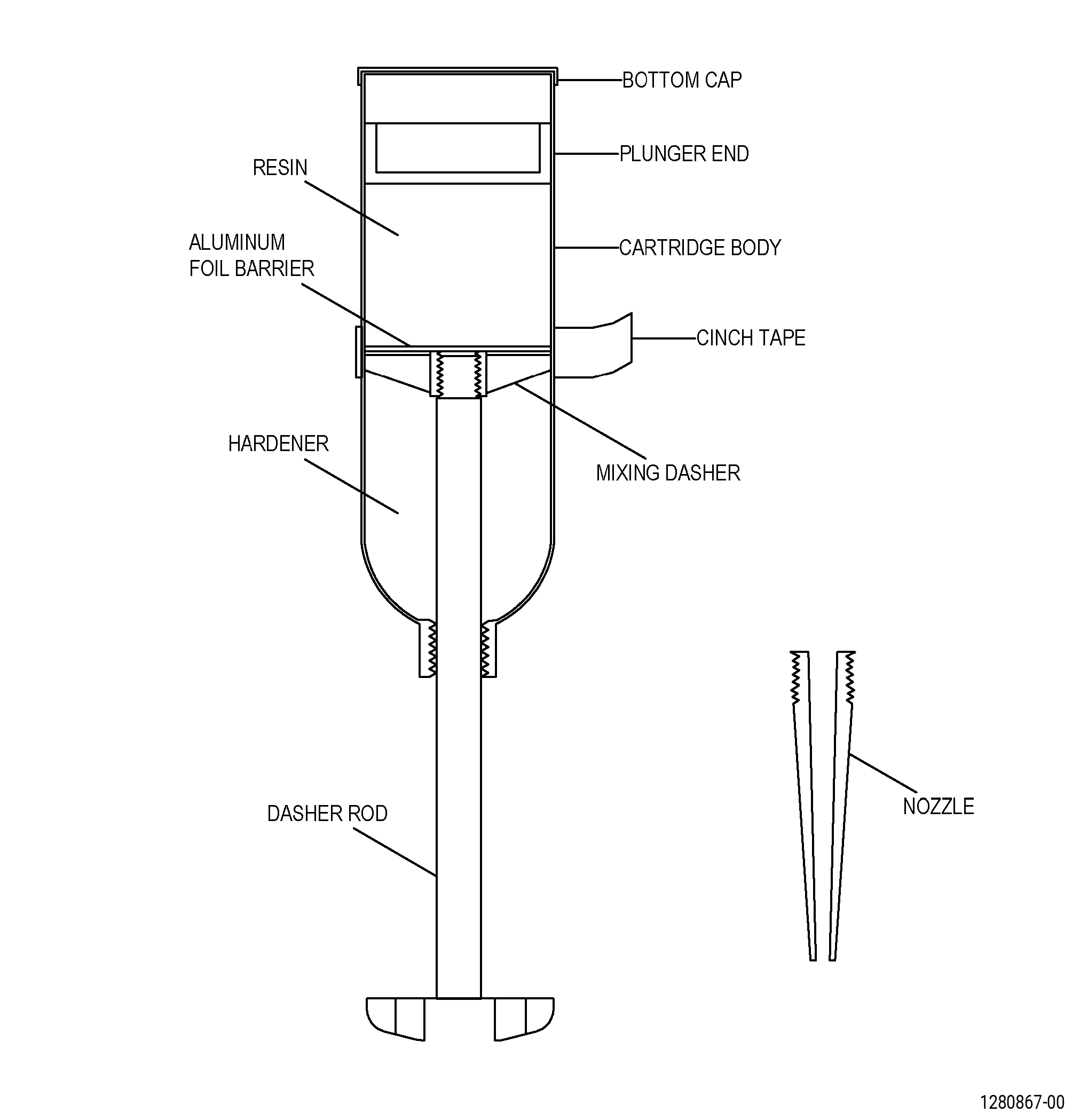
| (1).A. | Alternative Procedure. Prepare the C01-161 abradable material packaged in the 6.0 oz (170 g) adhesive cartridge. Refer to Figure 908 and as follows: |
| (a) | Remove the cinch tape from the cartridge. |
| (b) | Pull the dasher rod up toward the threaded neck end of the cartridge. |
| NOTE: |
|
| (c) | Push the cartridge sides in the foil to cause damage to the foil barrier. |
| (d) | Push the dasher rod to the plunger end of the cartridge to take out the damaged foil barrier. |
| (e) | Put the dasher rod on the spindle of the drive mixer. |
| (f) | Turn the drive mixer on. |
| (g) | Hold the cartridge body and push and pull the cartridge body up and down for 4 minutes and do as follows: |
| 1 | Make sure that the dasher touches the two ends of the cartridge when it operates through its full movement. |
| 2 | Complete a minimum of 120 full movements during 4 minutes. |
| (h) | Stop the drive mixer. |
| (i) | Remove the bottom cap. |
| (j) | Push the dasher rod to the plunger end of the cartridge and hold the cartridge tightly at the plunger end. |
| (k) | Turn the dasher rod counterclockwise to disconnect it from the mixing dasher. |
| (l) | Remove the dasher rod from the cartridge. |
| (m) | Put the nozzle into the neck end of the cartridge. |
| (n) | Put the cartridge into a dispensing gun. |
| (o) | Make sure that you remove the material from the cartridge in 2 minutes or less after you mixed it. |
| NOTE: |
|
| Subtask 72-00-01-350-010 |
| WARNING: |
|
| WARNING: |
|
| WARNING: |
|
| WARNING: |
|
| CAUTION: |
|
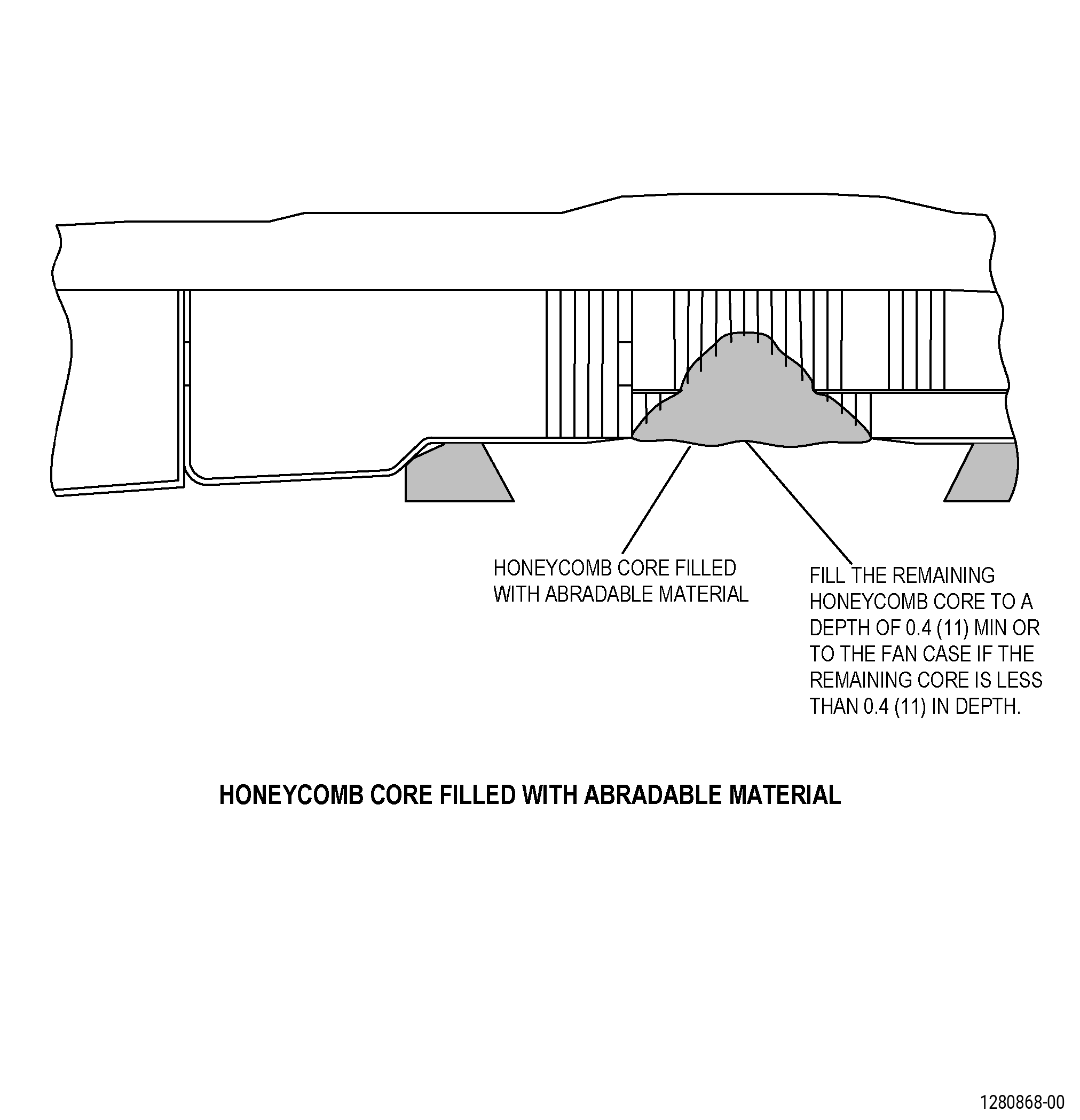
| O. | Put the C01-161 abradable material in the honeycomb cells. Refer to Figure 909 and as follows: |
| (1) | Remove the masking from the repair area before the C01-161 abradable material is applied. |
| (2) | Use a C10-108 brush and the Teflon spatula to push the C01-161 abradable material to the top of all the honeycomb cells. |
| (3) | Fill the cells to approximately 0.4 inches (10 mm) in depth. |
| (4) | Use the Teflon spatula to make the C01-161 abradable material level with or a small amount above the top of the honeycomb cells. |
| Subtask 72-00-01-110-015 |
| P. | Remove the unwanted C01-161 abradable material from around the edge of the honeycomb as follows: |
| WARNING: |
|
| (1) | Use a C10-182 cleaning cloth moist with C04-035 isopropyl alcohol. |
| Subtask 72-00-01-220-097 |
| Q. | Do an inspection of the C01-161 abradable material as follows: |
| (1) | If the C01-161 abradable material moves, use the Teflon spatula to smooth the C01-161 abradable material level with the top of the honeycomb cells. |
| Subtask 72-00-01-370-001 |
| WARNING: |
|
| R. | Alternative Procedure Available. Cure the C01-161 abradable material. Refer to SAE ARP 5144 Heat Application for Thermosetting Resin Curing, and as follows: |
| (1) | Cure the C01-161 abradable material for a minimum of 24 hours at a temperature range of 77 to 100°F (25 to 38°C). |
| (2) | If the ambient temperature is less than 77°F (25°C) you can use heat lamps or a thermal blanket to increase the temperature to 77°F (25°C) as follows: |
| (a) | Use a thermocouple to monitor the temperature. |
| (b) | Keep the temperature to a range of 77 to 100°F (25 to 38°C). |
| (3) | If the ambient temperature is above 77°F (25°C), do not increase the temperature. |
| NOTE: |
|
| Subtask 72-00-01-370-002 |
| WARNING: |
|
| WARNING: |
|
| R.A. | Alternative Procedure. Cure the C01-161 abradable material. Refer to SAE ARP 5144 Heat Application for Thermosetting Resin Curing, and as follows: |
| (1) | Cure the C01-161 abradable material for 3 hours at a temperature of 77°F (25°C) and do as follows: |
| (a) | If the ambient temperature is less than 77°F (25°C) you can use heat lamps or a thermal blanket to increase the temperature to 77°F (25°C), and as follows: |
| 1 | Use a thermocouple to monitor the temperature. |
| 2 | Keep the temperature at a range of 77 to 100°F (25 to 38°C). |
| (b) | If the ambient temperature is above 77°F (25°C), do not increase the temperature. |
| NOTE: |
|
| (2) | Increase the temperature of the C01-161 abradable material to a range of 100 to 120°F (38 to 49 °C) for a minimum of 2 hours and do as follows: |
| (a) | Use a heat lamp, thermal blanket or heat gun on the repair area to increase the temperature. |
| (b) | Use a minimum of 3 equally spaced thermocouples around the repair area. |
| Subtask 72-00-01-140-003 |
| WARNING: |
|
| S. | Sand the forward fan case C01-161 abradable material to make it smooth as follows: |
| (1) | Use C10-141 abrasive paper. |
| Subtask 72-00-01-160-003 |
| WARNING: |
|
| T. | Clean the dust from the forward fan case repair area with clean, dry, compressed air that contains no oil. |
| Subtask 72-00-01-110-006 |
| U. | Clean the forward fan case damaged area. Refer to TASK 70-46-01-350-030 (MASKING AND CLEANING OF EPOXY AND POLYESTER MATRIX THERMOSETTING COMPOSITE MATERIALS), and as follows: |
| (1) | Use Composite Cleaning Method No. 4 or Composite Cleaning Method No. 5. |
| WARNING: |
|
| (2) | Use C04-035 isopropyl alcohol. |
| Subtask 72-00-01-220-098 |
| V. | Do an inspection of the surface of the C01-161 abradable material as follows: |
| (1) | Make sure that the repair area has the same contour as the honeycomb cells. |
| (2) | If the shape of the repaired area of the C01-161 abradable material is below the contour of the edge of the taper, do Subtask 72-00-01-350-010 (paragraph 5.O.) thru Subtask 72-00-01-110-006 (paragraph 5.U.) again. |
| (3) | If the surface of the C01-161 abradable material has voids more than 0.125 inch (3.18 mm) in width, do as follows: |
| (a) | Fill the voids with the C01-161 abradable material. Refer to Subtask 72-00-01-350-010 (paragraph 5.O.) thru Subtask 72-00-01-110-006 (paragraph 5.U.). |
| Subtask 72-00-01-350-012 |
| W. | Apply masking to the forward fan case repair areas. Refer to TASK 70-46-01-350-030 (MASKING AND CLEANING OF EPOXY AND POLYESTER MATRIX THERMOSETTING COMPOSITE MATERIALS), and as follows: |
| (1) | Use Composite Masking Method No. 4. |
| (2) | Apply the masking until you apply the adhesive. |
| Subtask 72-00-01-350-054 |
| X. | Alternative Procedure Available. Make an SPD facesheet as follows: |
| NOTE: |
|
| Subtask 72-00-01-930-005 |
| (1) | Make an aluminum tool to support the C10-003 glass fabric when you do the ply layup and curing procedure and as follows: |
| (a) | Make the tool to a contour that agrees with the repair area. |
| Subtask 72-00-01-350-055 |
| (b) | Put a layer of C10-142 polyester film or C10-137 vacuum bag film on the tool. |
| WARNING: |
|
| (2) | Make the SPD of sufficient size and with the same number of plies that you removed from the repair area. Refer to Figure 910 and as follows: |
| (a) | Make an SPD facesheet template larger than the prepared repair area. |
| NOTE: |
|
| (b) | Make sure that the SPD facesheet agrees with the material, contour and ply thickness in the repair area. |
| (c) | Count the number of plies that you will need and do as follows: |
| 1 | Get sufficient C10-003 glass fabric for all the plies. |
| (d) | Put the C10-003 glass fabric on a new piece of C10-142 polyester film or C10-137 vacuum bag film. |
| WARNING: |
|
| WARNING: |
|
| CAUTION: |
|
| (e) | Prepare the C01-147 liquid adhesive as follows: |
| 1 | Make an estimate of the quantity of C01-147 liquid adhesive that you will use. |
| 2 | Use a clean metal or paper container that has no wax. |
| 3 | Mix each component in the ratio that follows: |
| a | Part A (adhesive)- 100 parts by weight. |
| b | Part B (catalyst) - 30 parts by weight. |
| 4 | Mix the adhesive components until you cannot see streaks of the two components. |
| NOTE: |
|
| (f) | Apply the C01-147 liquid adhesive on the C10-003 glass fabric with a new and clean C10-108 brush. |
| (g) | Put a second piece of new C10-142 polyester film or C10-137 vacuum bag film on top of the C10-003 glass fabric and C01-147 liquid adhesive. |
| (h) | Use the Teflon spatula to push the C01-147 liquid adhesive into the C10-003 glass fabric until the two sides are fully wet with C01-147 liquid adhesive. |
| (i) | Use the Teflon spatula to remove all the caught air and the unwanted liquid adhesive. |
| (j) | Put a mark on the forward fan case. Refer to TASK 70-16-00-350-001 (MARKING PRACTICES), TASK 70-16-02-350-017 (TEMPORARY MARKING), and as follows: |
| 1 | Put the SPD facesheet template on the C10-142 polyester film or C10-137 vacuum bag film and make a line around it. |
| 2 | Make the quantity of plies the same as the number of plies removed from the repair area. |
| 3 | Put the SPD facesheet template in a position that gives a 45 degree offset with alternating plies. |
| WARNING: |
|
| (k) | Cut the plies along the lines that you made on the C10-142 polyester film or C10-137 vacuum bag film. |
| (l) | Remove one side of the polyester film or vacuum bag film from the first ply. |
| (m) | Put the C10-003 glass fabric ply with the side that you removed from the C10-142 polyester film or the C10-137 vacuum bag film on the support tool. |
| (n) | Remove the top piece of polyester film or vacuum bag film from the first C10-003 glass fabric ply. |
| (o) | Apply a layer of C01-147 liquid adhesive of approximate 0.010 inch (0.25 mm) in thickness on the first piece of C10-003 glass fabric as follows: |
| 1 | Use a new, clean C10-108 brush to apply the C01-147 liquid adhesive. |
| 2 | Use the Teflon spatula to remove all the caught air and make the C01-147 liquid adhesive smooth. |
| (p) | Put the next piece of C10-003 glass fabric on the previous ply as follows: |
| 1 | Remove the polyester film or the vacuum bag film from one side of the piece of C10-003 glass fabric. |
| 2 | Align the weave of the C10-003 glass fabric with the previous ply to a 45 degree offset. |
| 3 | Use the Teflon spatula to remove all the caught air and make the C01-147 liquid adhesive smooth. |
| 4 | Remove the polyester film or the vacuum bag film from the second side of the ply. |
| Subtask 72-00-01-370-016 |
| (q) | Do Subtask 72-00-01-350-055 (paragraph 5.X.(2)(o)) thru Subtask 72-00-01-350-055 (paragraph 5.X.(2)(p)) again for the remaining plies. |
| Subtask 72-00-01-360-006 |
| WARNING: |
|
| (r) | Make an envelope type vacuum bag to put around the SPD facesheet and support tool. Refer to TASK 70-46-03-360-003 (VACUUM BAGGING OF THERMOSETTING COMPOSITE REPAIRS), and as follows: |
| 1 | Use Method 1, Vertical Bleed Cure. |
| Subtask 72-00-01-370-017 |
| (s) | Alternative Procedure Available. Let the mixed adhesive cure for 3-5 days at a minimum temperature of 65°F (18°C). |
| Subtask 72-00-01-370-003 |
| WARNING: |
|
| (s).A. | Alternative Procedure. Let the mixed adhesive cure for 8 hours at a minimum temperature of 65°F (18°C) followed by a minimum of 1 hour at a temperature range of 180 to 200°F (82 to 93°C). |
| (t) | Remove the polyester film. |
| Subtask 72-00-01-350-056 |
| (3) | Make the cured SPD facesheet to fit the repair area as follows: |
| (a) | Use the same taper angle that you made on the facesheet. Refer to Figure 910. |
| WARNING: |
|
| (b) | Sand the SPD facesheet to get a smooth matte finish as follows: |
| NOTE: |
|
| 1 | Use C10-141 abrasive paper. |
| Subtask 72-00-01-160-008 |
| WARNING: |
|
| (c) | Remove the dust from the SPD facesheet with clean, dry, compressed air that contains no oil. |
| Subtask 72-00-01-350-057 |
| WARNING: |
|
| WARNING: |
|
| CAUTION: |
|
| (4) | Prepare the C01-155 paste adhesive as follows: |
| (a) | Make an estimate of the quantity of the C01-155 paste adhesive that you will use. |
| (b) | Use a clean metal or paper container that has no wax. |
| (c) | Mix each component in the ratio that follows: |
| 1 | Part A (adhesive)- 100 parts by weight. |
| 2 | Part B (catalyst)- 17 parts by weight. |
| (d) | Mix the adhesive components until you cannot see streaks of the components. |
| NOTE: |
|
| Subtask 72-00-01-360-007 |
| (5) | Bond the SPD facesheet to the forward fan case repair area as follows: |
| (a) | Remove all the masking from the repair area. |
| (b) | Apply sufficient masking to the surfaces adjacent to the forward fan case repair area to prevent unwanted adhesive on the external surfaces. Refer to TASK 70-46-01-350-030 (MASKING AND CLEANING OF EPOXY AND POLYESTER MATRIX THERMOSETTING COMPOSITE MATERIALS) and do as follows: |
| 1 | Use Composite Masking Method No 3. |
| (c) | Apply the C01-155 paste adhesive on the bonding surfaces of the SPD facesheet and the repair area with a new and clean C10-108 brush. |
| (d) | Put the SPD facesheet in the repair area. |
| (e) | Apply a layer of C10-133 FEP film on the facesheet repair area. |
| (f) | Use the Teflon spatula to rub the C10-133 FEP film on the bond lines to make the repair area smooth. |
| (g) | Use a clean C10-182 cleaning cloth to remove the unwanted resin. |
| Subtask 72-00-01-350-058 |
| (6) | Let the mixed C01-155 paste adhesive cure. Refer to Subtask 72-00-01-370-004 (paragraph 5.Y.) or Subtask 72-00-01-370-005 (paragraph 5.Y.A.). |
| (a) | Use C10-136 tape to keep the C10-133 FEP film and the SPD facesheet in place until you cure the C01-155 paste adhesive fully. |
| Subtask 72-00-01-140-010 |
| WARNING: |
|
| (7) | Sand the cured SPD facesheet and facesheet to prepare the repair area for bonding a cover ply as follows: |
| (a) | Use C10-141 abrasive paper. |
| (b) | Use a belt sander or sand manually to get a smooth, matte finish. |
| NOTE: |
|
| (c) | Sand an area that is larger on all sides than the SPD facesheet repair area. |
| Subtask 72-00-01-110-016 |
| (8) | Clean the repair area. Refer to TASK 70-46-01-350-030 (MASKING AND CLEANING OF EPOXY AND POLYESTER MATRIX THERMOSETTING COMPOSITE MATERIALS), and as follows: |
| (a) | Use Composite Cleaning Method No. 5. |
| WARNING: |
|
| (b) | Use C04-035 isopropyl alcohol. |
| Subtask 72-00-01-350-059 |
| (9) | Make a cover ply to bond on the repair area. |
| (a) | Make a cover ply template that is larger on all sides than the SPD repair area. |
| (b) | Get sufficient C10-003 glass fabric for this ply. |
| (c) | Put the C10-003 glass fabric on a new piece of C10-142 polyester film or C10-137 vacuum bag film. |
| WARNING: |
|
| WARNING: |
|
| CAUTION: |
|
| (d) | Prepare the C01-147 liquid adhesive as follows: |
| 1 | Make an estimate of the quantity of C01-147 liquid adhesive that you will use. |
| 2 | Use a clean metal or paper container that has no wax. |
| 3 | Mix each component in the ratio that follows: |
| a | Part A (adhesive)- 100 parts by weight. |
| b | Part B (catalyst) - 30 parts by weight. |
| 4 | Mix the adhesive components until you cannot see streaks of the two components. |
| NOTE: |
|
| (e) | Apply C01-147 liquid adhesive on the C10-003 glass fabric with a new and clean C10-108 brush. |
| (f) | Put a second piece of new C10-142 polyester film or C10-137 vacuum bag film on top of the C10-003 glass fabric and the adhesive. |
| (g) | Use the Teflon spatula to push the C01-147 liquid adhesive into the C10-003 glass fabric until the two sides are fully wet with C01-147 liquid adhesive. |
| (h) | Use the Teflon spatula to remove all the caught air and the unwanted liquid adhesive. |
| (i) | Put a mark on the forward fan case. Refer to TASK 70-16-00-350-001 (MARKING PRACTICES), TASK 70-16-02-350-017 (TEMPORARY MARKING), and as follows: |
| 1 | Put the cover ply template on the C10-142 polyester film or C10-137 vacuum bag film and make a line around it. |
| 2 | Put the cover ply template in a position that gives a 45 degree offset with the facesheet fabric weave. |
| WARNING: |
|
| (j) | Cut the ply along the lines that you made on the C10-142 polyester film. |
| Subtask 72-00-01-360-008 |
| (10) | Bond the cover ply to the facesheet repair area as follows: |
| (a) | Apply a layer of C01-147 liquid adhesive of an approximate 0.010 inch (0.25 mm) in thickness on the facesheet repair area as follows: |
| 1 | Use a new, clean C10-108 brush to apply the C01-147 liquid adhesive. |
| 2 | Use the Teflon spatula to remove all the caught air and make the C01-147 liquid adhesive smooth. |
| (b) | Remove one side of the polyester film or vacuum bag film from the cover ply. |
| (c) | Put the cover ply on the facesheet repair area as follows: |
| 1 | Put the cover ply in position to make an overlap of the facesheet on all sides. |
| (d) | Apply a layer of C10-133 FEP film over the facesheet repair area. |
| (e) | Use the Teflon spatula to rub the C10-133 FEP film to make the repair area smooth and remove the caught air. |
| (f) | Use a C10-182 cleaning cloth to remove the unwanted resin. |
| Subtask 72-00-01-350-060 |
| (11) | Let the mixed C01-147 liquid adhesive cure. Refer to Subtask 72-00-01-370-004 (paragraph 5.Y.) or Subtask 72-00-01-370-005 (paragraph 5.Y.A.) and as follows: |
| (a) | Use C10-136 tape to keep the C10-133 FEP film and the cover ply in place until you cure the C01-147 liquid adhesive fully. |
| Subtask 72-00-01-350-013 |
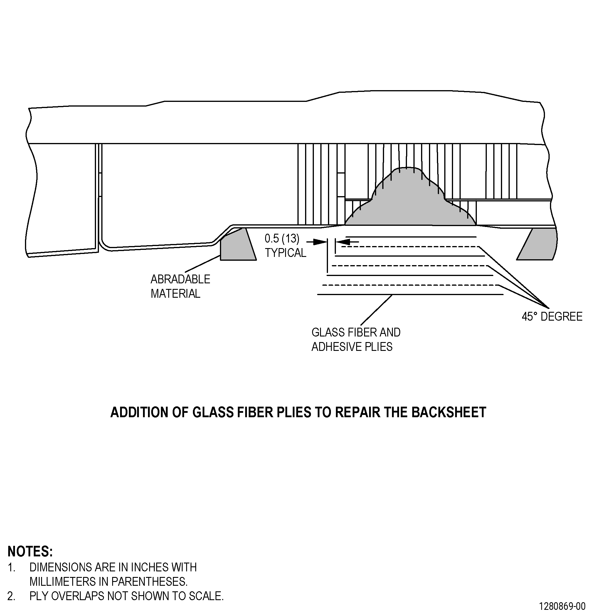
| X.A. | Alternative Procedure. Make glass fiber plies and do a wet layup. Refer to Figure 910 and as follows: |
| (1) | Make ply templates for the glass fiber plies as follows: |
| (a) | Count the number of plies that you removed from the facesheet. |
| (b) | Measure the ply taper length that you cut in the glass fiber facesheet repair area. |
| (c) | Use C10-142 polyester film or C10-137 vacuum bag film to make the ply templates. |
| (d) | Make the number of ply templates the same as the number of plies removed. |
| WARNING: |
|
| (e) | Cut the first ply template to the same size and shape as the filled area of the honeycomb and do as follows: |
| 1 | Put a mark on the ply template as a 0 degree or 90 degrees ply. Refer to TASK 70-16-00-350-001 (MARKING PRACTICES) and TASK 70-16-02-350-017 (TEMPORARY MARKING). |
| (f) | Cut the subsequent ply template 0.5 inch (13 mm) larger around the previous ply template and do as follows: |
| 1 | Put a mark on the ply template as a plus 45/minus 45 degrees ply. Refer to TASK 70-16-00-350-001 (MARKING PRACTICES) and TASK 70-16-02-350-017 (TEMPORARY MARKING). |
| (g) | Cut the subsequent ply template 0.5 inch (13 mm) larger around the previous ply template and do as follows: |
| 1 | Put a mark on the ply template as a 0 degree or 90 degrees ply. Refer to TASK 70-16-00-350-001 (MARKING PRACTICES) and TASK 70-16-02-350-017 (TEMPORARY MARKING). |
| (h) | Do Subtask 72-00-01-350-013 (paragraph 5.X.A.(1)(e)) and Subtask 72-00-01-350-013 (paragraph 5.X.A.(1)(f)) again until you have sufficient ply templates to fill the taper. |
| NOTE: |
|
| WARNING: |
|
| WARNING: |
|
| CAUTION: |
|
| CAUTION: |
|
| (2) | Prepare and apply the C01-155 paste adhesive as follows: |
| (a) | Make an estimate of the quantity of adhesive that you will use. |
| (b) | Mix the C01-155 paste adhesive in a clean metal or in an uncoated paper container. |
| (c) | Mix each component in the ratio that follows: |
| 1 | Part A (resin, gray material) - 100 parts by weigh. |
| 2 | Part B (catalyst, liquid) - 17 parts by weight. |
| (d) | Mix the adhesive components until you cannot see streaks of the two components. |
| NOTE: |
|
| (e) | Rub the C01-155 paste adhesive on the prepared surface of the C01-161 abradable material and the facesheet tapered area with a C10-108 brush. |
| (f) | Remove all the masking from the repair area. |
| (g) | Apply sufficient masking to the surfaces adjacent to the forward fan case repair area to prevent unwanted adhesive on the external surfaces. Refer to TASK 70-46-01-350-030 (MASKING AND CLEANING OF EPOXY AND POLYESTER MATRIX THERMOSETTING COMPOSITE MATERIALS) and do as follows: |
| 1 | Use Composite Masking Method No. 3. |
| (h) | Apply a layer of C01-155 paste adhesive of approximately 0.010 inch (0.25 mm) in thickness with a small spatula. |
| (i) | Remove the unwanted adhesive from around the repair area with a C10-182 cleaning cloth. |
| WARNING: |
|
| WARNING: |
|
| CAUTION: |
|
| (3) | Make the glass fiber and the adhesive plies as follows: |
| (a) | Prepare the C01-147 liquid adhesive and do as follows: |
| 1 | Make an estimate of the quantity of C01-147 liquid adhesive that you will use. |
| 2 | Use a clean metal or paper container that has no wax. |
| 3 | Mix each component in the ratio that follows: |
| a | Part A (adhesive)- 100 parts by weight. |
| b | Part B (catalyst) - 30 parts by weight. |
| 4 | Mix the adhesive components until you cannot see streaks of the two components. |
| NOTE: |
|
| (b) | Apply C01-147 liquid adhesive to the C10-003 glass fabric as follows: |
| 1 | Get sufficient C10-003 glass fabric for all the profile templates to have a correct fit and orientation without overlap. |
| 2 | Put the C10-003 glass fabric on a new piece of C10-142 polyester film or C10-137 vacuum bag film. |
| 3 | Apply the C01-147 liquid adhesive on the C10-003 glass fabric with a new and clean C10-108 brush. |
| 4 | Put a new piece of C10-142 polyester film or C10-137 vacuum bag film on top of the C10-003 glass fabric and C01-147 liquid adhesive. |
| 5 | Use the Teflon spatula to push the C01-147 liquid adhesive into the C10-003 glass fabric to fully wet both sides. |
| 6 | Remove all the air bubbles and the unwanted liquid adhesive. |
| (c) | Put the ply templates on the film covered C10-003 glass fabric. Make sure that the ply template is at the orientation written on the ply template. |
| WARNING: |
|
| (d) | Put a mark on the forward fan case. Refer to TASK 70-16-00-350-001 (MARKING PRACTICES) and TASK 70-16-02-350-017 (TEMPORARY MARKING), and as follows: |
| 1 | Make a line around the profile templates and cut out the ply shapes. |
| WARNING: |
|
| (4) | Put the plies on the repair area as follows: |
| (a) | Pull the C10-142 polyester film or C10-137 vacuum bag film from one side of the first piece of C10-003 glass fabric. Put the C10-003 glass fabric on the C01-155 paste adhesive and do as follows: |
| 1 | Use the Teflon spatula to remove all the wrinkles and the caught air before you remove the film from the second side of the ply. |
| (b) | Apply a layer of C01-147 liquid adhesive of 0.010 inch (0.25 mm) in thickness on the first piece of C10-003 glass fabric as follows: |
| 1 | Use a new, clean, C10-108 brush to apply the C01-147 liquid adhesive. |
| 2 | Use the Teflon spatula to remove all the caught air and make the C01-147 liquid adhesive smooth. |
| (c) | Put the second piece of C10-003 glass fabric on the first piece as follows: |
| 1 | Pull the C10-142 polyester film or C10-137 vacuum bag film from one side of the adjacent piece of C10-003 glass fabric. |
| 2 | Align the weave of the second piece of C10-003 glass fabric at 45 degrees to the first piece. |
| 3 | Use the Teflon spatula to remove all the wrinkles and the caught air. |
| 4 | Remove the film from the second side of the ply. |
| (d) | Do Subtask 72-00-01-350-013 (paragraph 5.X.A.(4)(b)) and Subtask 72-00-01-350-013 (paragraph 5.X.A.(4)(c)) and until you apply all the plies. |
| (e) | Apply a layer of C10-133 FEP film on the repair area. |
| (f) | Rub the C10-133 FEP film with the Teflon spatula from the center of the repair to the edge to remove the unwanted resin as follows: |
| 1 | Use a C10-182 cleaning cloth to remove the unwanted resin. |
| (g) | Keep the plies in place until the C01-147 liquid adhesive has fully cured. |
| Subtask 72-00-01-360-009 |
| WARNING: |
|
| (5) | Make a vacuum bag to put around the repair area. Refer to TASK 70-46-03-360-003 (VACUUM BAGGING OF THERMOSETTING COMPOSITE REPAIRS), and as follows: |
| (a) | Use Bagging Method 1, Vertical Bleed Cure. |
| (b) | If necessary, make a support to keep the vacuum bag away from the edge of the facesheet. |
| Subtask 72-00-01-370-004 |
| WARNING: |
|
| Y. | Alternative Procedure Available. Let the mixed adhesive cure for 3-5 days at a minimum temperature of 65°F (18°C). Refer to SAE ARP 5144, Heat Application for Thermosetting Resin Curing. |
| Subtask 72-00-01-370-005 |
| WARNING: |
|
| Y.A. | Alternative Procedure. Let the mixed adhesive cure. Refer to SAE ARP 5144, Heat Application for Thermosetting Resin Curing and as follows: |
| (1) | Let the mixed adhesive cure for a minimum of 8 hours at a minimum temperature of 65°F (18°C) |
| (2) | Increase the temperature of the repair area to a temperature range of 180 to 200°F (82 to 93°C) for a minimum of 1 hour. |
| Subtask 72-00-01-370-006 |
| Z. | Remove the FEP film. |
| Subtask 72-00-01-140-004 |
| WARNING: |
|
| AA. | Sand the forward fan case facesheet repair area to get a smooth matte finish as follows: |
| NOTE: |
|
| (1) | Use C10-141 abrasive paper to make the repair area agree with the adjacent contour. |
| Subtask 72-00-01-160-004 |
| WARNING: |
|
| AB. | Remove the dust from the forward fan case area with clean, dry, compressed air that contains no oil. |
| Subtask 72-00-01-160-005 |
| AC. | Clean the forward fan case damaged area. Refer to TASK 70-46-01-350-030 (MASKING AND CLEANING OF EPOXY AND POLYESTER MATRIX THERMOSETTING COMPOSITE MATERIALS), and as follows: |
| (1) | Use Composite Cleaning Method No. 4 or Composite Cleaning Method No. 5. |
| Subtask 72-00-01-350-014 |
| AD. | Mix the C01-161 abradable material. Refer to Subtask 72-00-01-350-008 (paragraph 5.N.). |
| Subtask 72-00-01-350-015 |
| WARNING: |
|
| AE. | Cut a piece of C10-142 polyester film or C10-137 vacuum bag film to use it as a cover for the repair area as follows: |
| (1) | The cover must be 10.0-12.0 inches (254-304 mm) larger than the repair area. |
| Subtask 72-00-01-350-016 |
| AF. | Use a C10-108 brush and the Teflon spatula to rub the C01-161 abradable material on all the surfaces of the repair areas and do as follows: |
| (1) | Make sure that there is no caught air in the C01-161 abradable material when you apply it. |
| Subtask 72-00-01-350-017 |
| AG. | Apply the remaining C01-161 abradable material. Refer to Figure 911 and as follows: |
| (1) | Put a small quantity of the C01-161 abradable material at one end of the repair to make the thickness higher than the remaining abradable seal and as follows: |
| (a) | Use sufficient C01-161 abradable material to fill approximately 3.0-4.0 inches (77-101 mm) of the circumferential length of the repair. |
| (2) | Put the cover on the C01-161 abradable material and do as follows: |
| (a) | Pull the cover tightly and hold it in the correct position with C10-136 tape or with your hands. |
| (3) | Use the profile template or the wooden roller to make the material agree with the contour of the adjacent material. |
| CAUTION: |
|
| (4) | Do Subtask 72-00-01-350-017 (paragraph 5.AG.(1)) thru Subtask 72-00-01-350-017 (paragraph 5.AG.(3)) again until the repair area is completely filled. |
| (5) | Keep the cover in the correct position until the C01-161 abradable material cure is completed. |
| Subtask 72-00-01-110-007 |
| AH. | Remove the unwanted abradable material from around the repair as follows: |
| WARNING: |
|
| (1) | Use a C10-182 cleaning cloth moist with C04-035 isopropyl alcohol. |
| Subtask 72-00-01-220-099 |
| AI. | Do an inspection of the C01-161 abradable material as follows: |
| (1) | If the C01-161 abradable material moves, use the wooden roller on the cover to smooth the C01-161 abradable material back to the contour of the material that is adjacent to the repair. |
| Subtask 72-00-01-370-007 |
| AJ. | Cure the C01-161 abradable material. Refer to Subtask 72-00-01-370-001 (paragraph 5.R.). |
| Subtask 72-00-01-350-018 |
| AK. | Remove the tape and the cover. |
| Subtask 72-00-01-140-005 |
| WARNING: |
|
| AL. | Sand the forward fan case abradable seal repaired area to agree with contour of the adjacent area, as follows: |
| (1) | Use C10-141 abrasive paper. |
| (2) | Use the profile template as a guide when you repair areas larger than 6.0 inches (152 mm) maximum axial dimension. |
| NOTE: |
|
| Subtask 72-00-01-220-100 |
| AM. | Do a visual inspection of the surface of the forward fan case abradable shroud as follows: |
| (1) | Make sure that the repair area has the same contour as the C01-161 abradable material adjacent to the repair area. |
| (2) | If necessary, fill the unwanted voids in the abradable shroud repair area as follows: |
| (a) | Do Subtask 72-00-01-350-008 (paragraph 5.N.) again to prepare the C01-161 abradable material. |
| (b) | Use a C10-108 brush to rub the C01-161 abradable material on the voids and fully wet the surfaces of the void. |
| (c) | Use the Teflon spatula to make the C01-161 abradable material smooth and agree with the contour of the abradable shroud repair area. |
| (d) | Do Subtask 72-00-01-140-005 (paragraph 5.AL.) again to make the repair area smooth. |
| (3) | If the forward fan case repair area does not agree with the inspection limits, do the repair again. |