| GENX-1B CLEANING,INSPECTION,AND REPAIR MANUAL | Dated: 08/22/2024 | |
| CIR 72-00-21 , INSPECTION 001 | ||
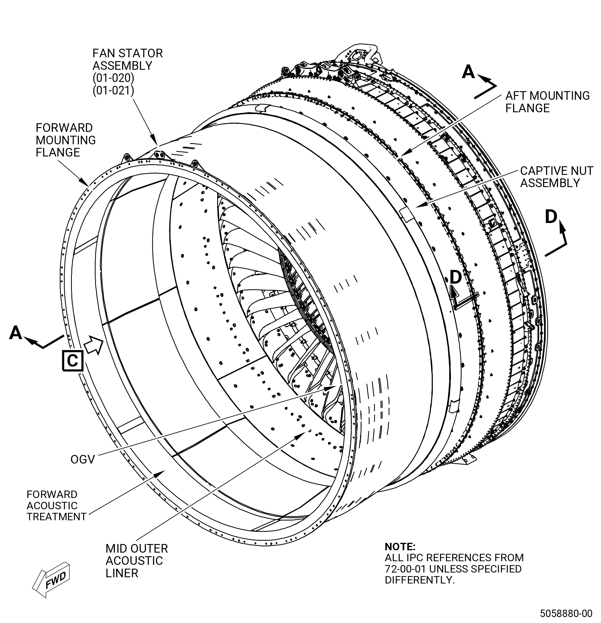
| FAN STATOR ASSEMBLY - INSPECTION | ||
| GENX-1B CLEANING,INSPECTION,AND REPAIR MANUAL | Dated: 08/22/2024 | |
| CIR 72-00-21 , INSPECTION 001 | ||
| FAN STATOR ASSEMBLY - INSPECTION | ||
| * * * FOR ALL |
| TASK 72-00-21-200-801 |
| 1 . | General. |
| A. | This procedure gives instructions to do an inspection of the fan stator case assembly (fan stator assembly) (00109). |
| B. | Any sub-assembly or part removed for access or limited workscope must be inspected in accordance with criteria within this section. If there is no criteria, the sub-assembly or part must receive a general visual inspection (GVI) for continued serviceability. Refer to TASK 72-00-00-200-805 (72-00-00, INSPECTION 001) . If required, the component can be hand-cleaned to do a visual inspection. Refer to TASK 70-21-01-110-001 (CLEANING METHOD NO. 1 - SOLVENT DEGREASING) or TASK 70-21-03-160-001 (CLEANING METHOD NO. 3 - STEAM CLEANING) . GVI can not be done to components identified in TASK 05-21-00-200-801 (05-21-00, LIFE LIMITS 001) that become piece part. These components must have their appropriate mandatory inspections done, unless stated differently in an applicable Service Bulletin. |
| C. | If you use this procedure and find that an assembly or part is unserviceable, refer to the applicable section of the engine manual for more disassembly and inspection procedures for the assembly or part. |
| D. | If you will completely disassemble the fan stator assembly, this inspection is not necessary. Refer to the applicable section of the engine manual for the inspection procedure for each part. |
| E. | The maintenance instructions in this Manual do not purport to cover all details or variations in equipment, nor do they provide for every possible contingency to be met in connection with installation, operation, maintenance, or GEAE certified repair facilities. The maintenance instructions are intended to be all-inclusive for a complete teardown and overhaul of the component or sub assembly. The individual procedures as written are one sequence based on General Electric experience. Alternate sequences to these maintenance instructions are at the discretion of the operator and/or overhaul shop provided the intent of the maintenance instructions is met. The operator and/or overhaul shop can select specific tasks to partially disassemble and assemble hardware or subassemblies based upon the on demand maintenance requirement of the individual engine work scope provided the final assembly configuration and requirements contained in the manual have been met. |
| F. | The forward fan case and the stator/aft fan case assembly are subassemblies of the fan stator assembly, which is a subassembly of the fan stator module. The aft fan case is a subassembly of the stator/aft fan case assembly. |
| 2 . | Tools, Equipment, and Materials. |
| NOTE: |
|
| A. | Tools and Equipment. |
| (1) | Special Tools. None. |
| (2) | Standard Tools and Equipment. |
|
| (3) | Locally Manufactured Tools. None. |
| B. | Consumable Materials. |
| C. | Referenced Procedures. |
|
| D. | Expendable Parts. None. |
| 3 . | Specific Inspection Procedure. |
| Subtask 72-00-21-230-002 |
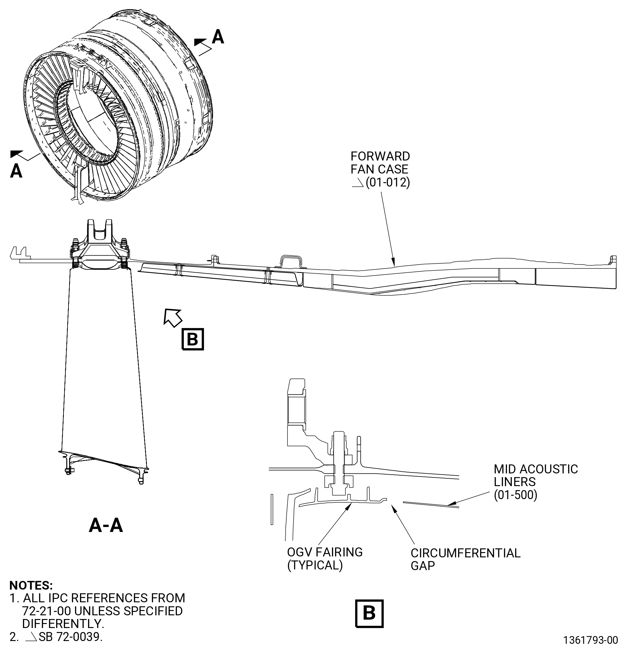
| A. | Do a spot-fluorescent-penetrant inspection to find all cracks on the forward fan containment case assembly (forward fan case) (01-011 , 72-21-00) or (01-012 , 72-21-00) and aft fan case (01-020 , 72-21-00). Refer to TASK 70-32-03-230-002 (SPOT-FLUORESCENT-PENETRANT INSPECTION). |
| Subtask 72-00-21-280-001 |
| B. | Do an inspection of the abradable shroud for looseness with a 0.375 inch (9.53 mm) diameter, 2.0 inches (51 mm) in length, round end rod as follows: |
| (1) | Tap on the shroud while you listen for a clicking sound. Refer to Subtask 72-00-21-220-004, (paragraph 4.A.). |
| 4 . | Visual Inspection. |
| Subtask 72-00-21-220-001 |
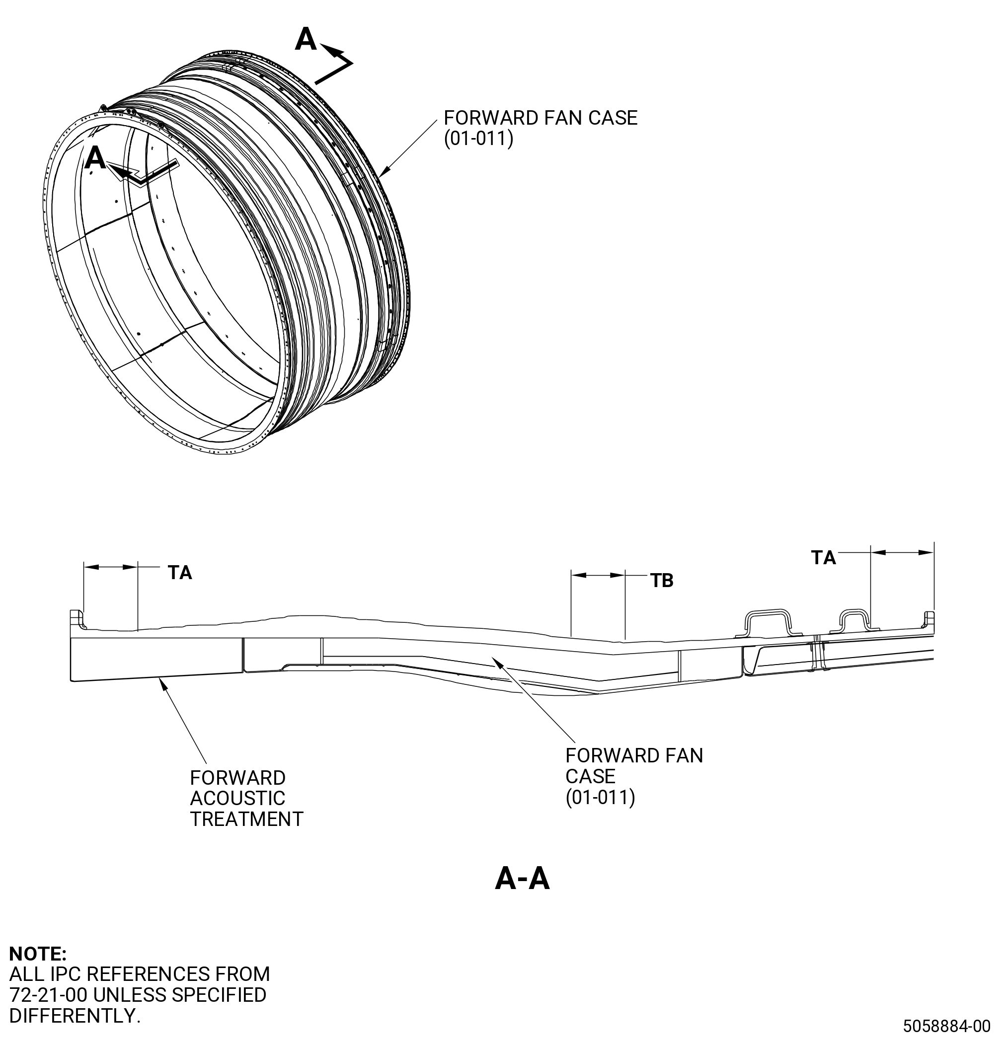
| A. | Do an inspection of the forward fan case (01-011 , 72-21-00) or (01-012 , 72-21-00). Refer to Figure 801. |
|
|
| Subtask 72-00-21-220-002 |
| (1) | Axial crack adjacent to the abradable panel joints: |
| Maximum serviceable limit: |
|
| Repair method: |
|
| Subtask 72-00-21-220-003 |
| (2) | Diagonal abradable panel joint cracks: |
| NOTE: |
|
| Maximum serviceable limit: |
|
| Repair method: |
|
| Subtask 72-00-21-220-004 |
| (3) | Voids, wear grooves, rubs, and areas not bonded to the facesheet: |
| Maximum serviceable limit: |
|
| • |
|
| • |
|
| • |
|
| Repair method: |
|
| Subtask 72-00-21-220-005 |
| (4) | Cracks in the eight trench filler panel joints and eight abradable panel joints: |
| Maximum serviceable limit: |
|
| Repair method: |
|
| Subtask 72-00-21-220-061 |
| (5) | Axial crack adjacent to the abradable panel joints: |
| Maximum serviceable limit: |
|
| Repair method: |
|
| Subtask 72-00-21-220-006 |
| (6) | Spalled, loose, or missing abradable material in the transition zones: |
| Maximum serviceable limit: |
|
| Repair method: |
|
| Subtask 72-00-21-220-060 |
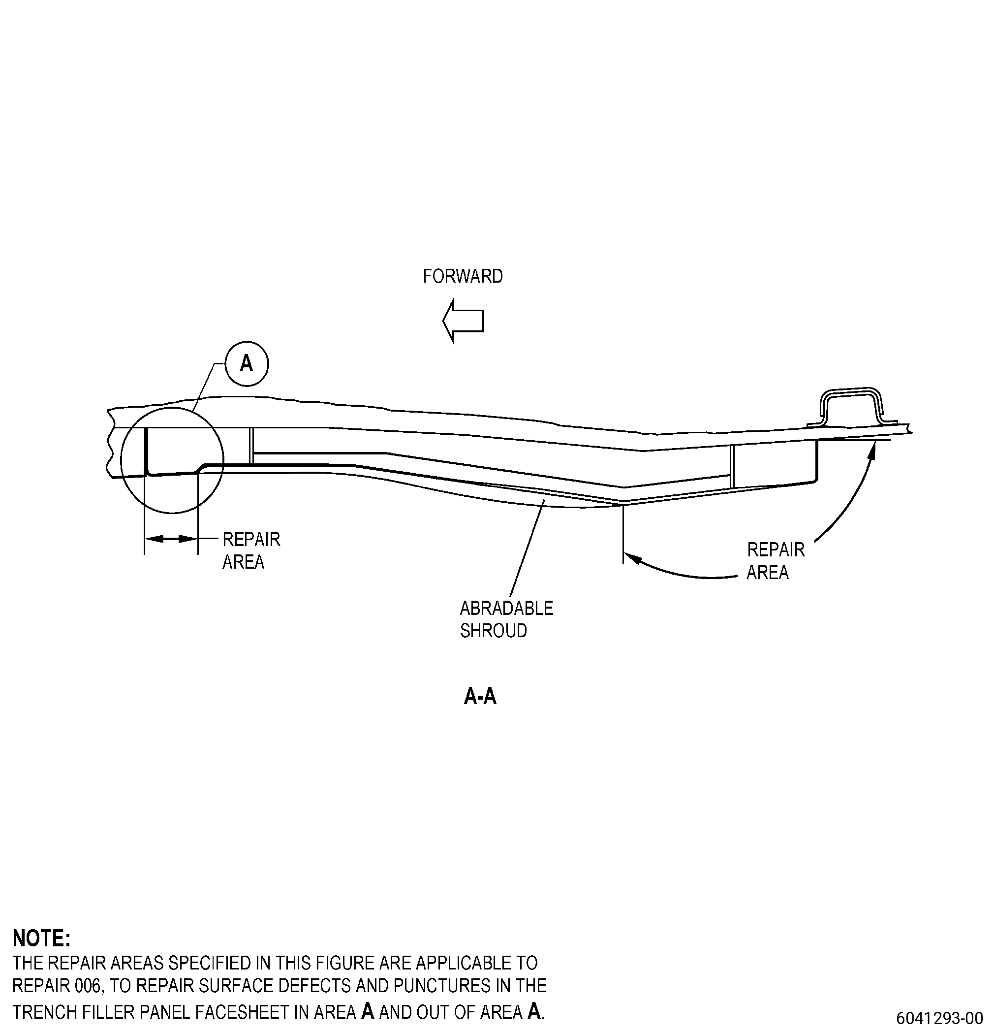
| (7) | Surface defects and punctures in the trench filler facesheet of area A. Refer to Figure 802, Figure 813, and Figure 814. |
| Maximum serviceable limit: |
|
| Repair method: |
|
| Subtask 72-00-21-220-086 |
| (8) | Surface defects and punctures in the trench filler facesheet outside of area A. Refer to Figure 802, Figure 813, and Figure 814. |
| Maximum serviceable limit: |
|
| Repair method: |
|
| Subtask 72-00-21-220-087 |
| (9) | Damaged, cracked, torn, punctured or disbonded polysulfide coating in the trench filler spaces: |
| Maximum serviceable limit: |
|
| Repair method: |
|
| Subtask 72-00-21-220-008 |
| B. | Do an inspection of the forward ”A” and aft “B” mounting flanges of the forward fan case (83500) as follows. Refer to Figure 801. |
| (1) | Missing glass plies or tear outs: |
| Maximum serviceable limit: |
|
| NOTE: |
|
| Repair method: |
|
| Subtask 72-00-21-220-009 |
| (2) | Cracks on the outer diameter surface: |
| Maximum serviceable limit: |
|
| Repair method: |
|
| Subtask 72-00-21-220-029 |
| (3) | Delamination in the flanges: |
| Maximum serviceable limit: |
|
| Repair method: |
|
| Subtask 72-00-21-220-030 |
| (4) | Nicks, dents, scratches, rubs, and scuffs on flanges (except the OD surface of flanges): |
| Maximum serviceable limit: |
|
| Repair method: |
|
| Subtask 72-00-21-220-088 |
| (5) | Nicks, dents, scratches, rubs, scuffs, and fretting on the OD surfaces in area C (tear out zone). Refer to Figure 803: |
| Maximum serviceable limit: |
|
| Repair method: |
|
| Subtask 72-00-21-220-089 |
| (6) | Nicks, dents, scratches, rubs, scuffs, and fretting on the OD surface of flanges in area D (outside of tear out zone). Refer to Figure 803: |
| Maximum serviceable limit: |
|
| Repair method: |
|
| Subtask 72-00-21-220-062 |
| (7) | Pitting: |
| NOTE: |
|
| Maximum serviceable limit: |
|
| Repair method: |
|
| Subtask 72-00-21-220-073 |
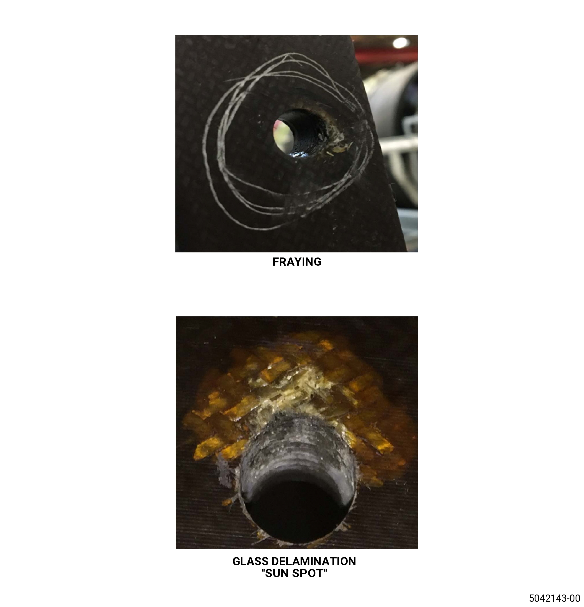
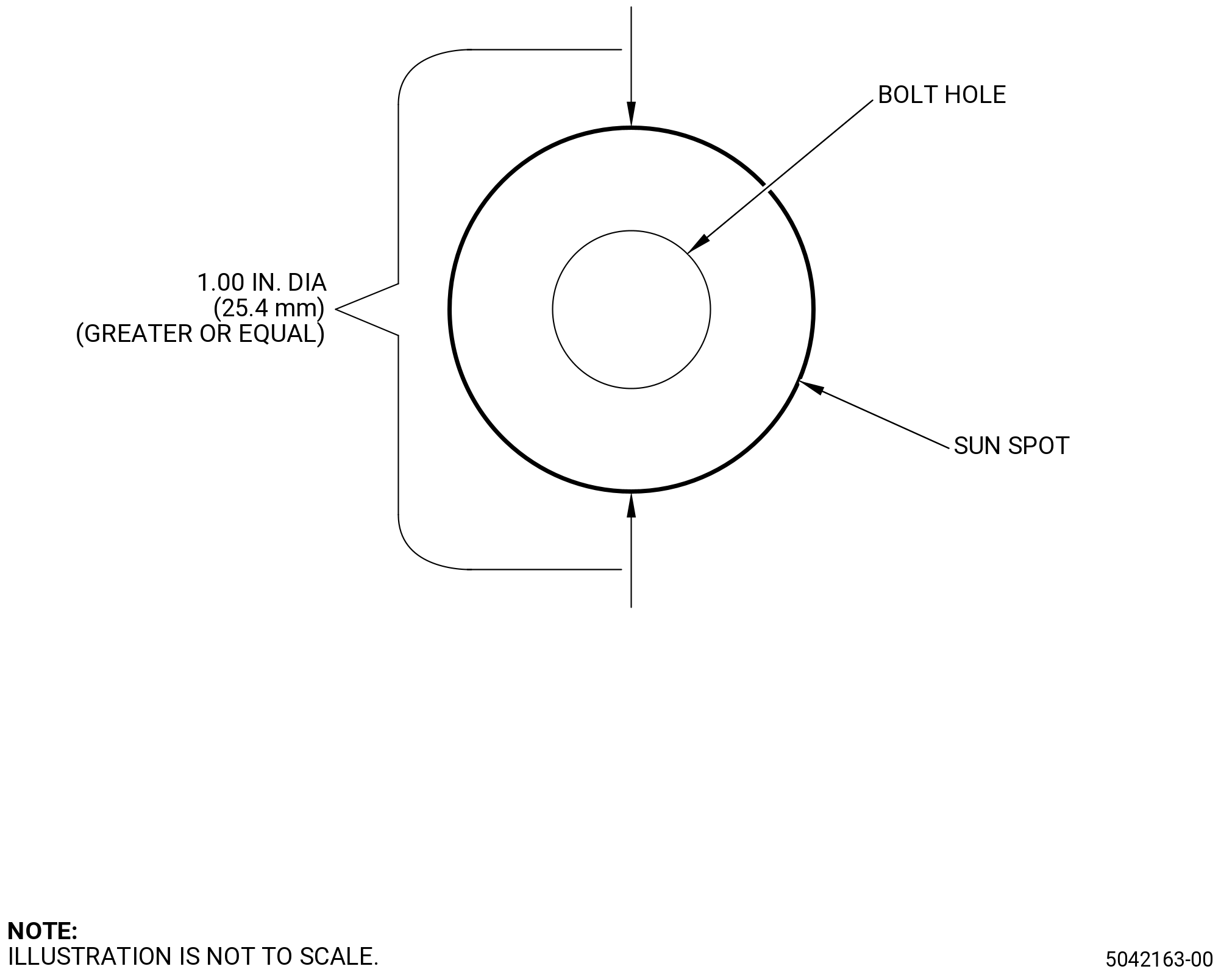
| (8) | Bolthole edge ply damage "sun spot": |
| Maximum serviceable limit: |
|
| Repair method: |
|
| NOTE: |
|
| Subtask 72-00-21-220-090 |
| (9) | Flaying at the bolthole edges. Refer to Figure 808: |
| Maximum serviceable limit: |
|
| Repair method: |
|
| Subtask 72-00-21-220-091 |
| (10) | Missing epoxy resin on the flange faces, edge and casing shell. Refer to Figure 804: |
| NOTE: |
|
| Maximum serviceable limit: |
|
| Repair method: |
|
| Subtask 72-00-21-220-092 |
| (11) | Crazing on resin rich areas at corner of flange with inner diameter. Refer to Figure 805: |
| NOTE: |
|
| Maximum serviceable limit: |
|
| Repair method: |
|
| Subtask 72-00-21-220-010 |
| C. | Do an inspection of all areas of the outer liner mid acoustics (mid acoustic liners) (01-500 , 72-21-00) on the forward fan case (83500) as follows. Refer to Figure 801. |
| (1) | Cracks: |
| Maximum serviceable limit: |
|
| Repair method: |
|
| Subtask 72-00-21-220-011 |
| (2) | Nicks and scratches on the facesheet: |
| Maximum serviceable limit: |
|
| Repair method: |
|
| Subtask 72-00-21-220-012 |
| (3) | Tears and cuts in the facesheet: |
| Maximum serviceable limit: |
|
| Repair method: |
|
| Subtask 72-00-21-220-013 |
| (4) | Delamination: |
| Maximum serviceable limit: |
|
| Repair method: |
|
| Subtask 72-00-21-220-014 |
| (5) | Loose screws: |
| Maximum serviceable limit: |
|
| Maximum repairable limit: |
|
| Repair method: |
|
| Subtask 72-00-21-220-031 |
| (6) | Missing screws: |
| Maximum serviceable limit: |
|
| Maximum repairable limit: |
|
| Repair method: |
|
| Subtask 72-00-21-220-015 |
| (7) | Holes, cuts, or tears in the C01-176 RTV 133 in the circumferential gap between the mid acoustic liners and the outlet guide vane (OGV) fairing. Refer to Figure 807. |
| Maximum serviceable limit: |
|
| Maximum repairable limit: |
|
| Repair method: |
|
|
|
| Subtask 72-00-21-220-016 |
| D. | Do an inspection of the captive nut assemblies on the forward fan case (83500) as follows. Refer to Figure 801. |
| (1) | Loose or missing rivets: |
| Maximum serviceable limit: |
|
| Maximum repairable limit: |
|
| Repair method: |
|
| Subtask 72-00-21-220-032 |
| (2) | Damaged captive nut cage: |
| Maximum serviceable limit: |
|
| Maximum repairable limit: |
|
| Repair method: |
|
| Subtask 72-00-21-220-033 |
| E. | Do an inspection of the casing shell outer diameter on the forward fan case (83500) as follows. Refer to Figure 801. |
| (1) | Nicks, dents, scratches, rubs, and scuffs: |
| Maximum serviceable limit: |
|
| NOTE: |
|
| Repair method: |
|
| Subtask 72-00-21-220-034 |
| (2) | Damage to the carbon fibers (below the protective plies) 0.015 inch (0.38 mm) in depth: |
| Maximum serviceable limit: |
|
| Repair method: |
|
| Subtask 72-00-21-220-063 |
| (3) | Tool marks. Refer to Figure 808. |
| NOTE: |
|
| Maximum serviceable limit: |
|
| • |
|
| • |
|
| Repair method: |
|
| Subtask 72-00-21-220-064 |
| (4) | In-plane wrinkles in the flanges and the casing shell: |
| NOTE: |
|
| Maximum serviceable limit: |
|
| Repair method: |
|
| Subtask 72-00-21-220-065 |
| (5) | Resin ridges in the casing shell: |
| NOTE: |
|
| Maximum serviceable limit: |
|
| Repair method: |
|
| Subtask 72-00-21-220-066 |
| (6) | Surface crazing: |
| NOTE: |
|
| Maximum serviceable limit: |
|
| Repair method: |
|
| Subtask 72-00-21-220-067 |
| (7) | Surface cracks: |
| NOTE: |
|
| Maximum serviceable limit: |
|
| Repair method: |
|
| Subtask 72-00-21-220-068 |
| (8) | Surface porosity: |
| NOTE: |
|
| Maximum serviceable limit: |
|
| Repair method: |
|
| Subtask 72-00-21-220-093 |
| (9) | Missing epoxy resin: |
| NOTE: |
|
| Maximum serviceable limit: |
|
| Repair method: |
|
| Subtask 72-00-21-220-035 |
| F. | Do an inspection of the stiffening hats on the forward fan case casing shell (83500) as follows. Refer to Figure 801. |
| (1) | Use a steel rod 0.375 inch (9.53 mm) in diameter and 2.00 inches (50.8 mm) in length with a round end to tap on the stiffening cap in the damaged area while listening for clicking sounds. |
| • |
|
| • |
|
| Subtask 72-00-21-220-069 |
| (2) | Nicks, dents, scratches, rubs, and scuffs: |
| (a) | Use a steel rod 0.375 inch (9.53 mm) in diameter and 2.00 inches (50.8 mm) in length with a round end to tap on the stiffening cap in the damaged area while listening for clicking sounds. |
| • |
|
| • |
|
| Maximum serviceable limit: |
|
| Repair method: |
|
| • |
|
| • |
|
| Subtask 72-00-21-220-036 |
| (3) | Disbonds between stiffening hats to casing shell: |
| Maximum serviceable limit: |
|
| Repair method: |
|
| Subtask 72-00-21-220-094 |
| (4) | Missing epoxy resin: |
| NOTE: |
|
| Maximum serviceable limit: |
|
| Repair method: |
|
| Subtask 72-00-21-220-037 |
| G. | Do an inspection of the stiffening caps on the forward fan case (83500) casing shell as follows. Refer to Figure 801. |
| (1) | Use a steel rod 0.375 inch (9.53 mm) in diameter and 2.00 inches (50.8 mm) in length with a round end to tap on the stiffening cap in the damaged area while listening for clicking sounds. |
| • |
|
| • |
|
| Subtask 72-00-21-220-070 |
| (2) | Nicks, dents, scratches, rubs, and scuffs: |
| (a) | Use a steel rod 0.375 inch (9.53 mm) in diameter and 2.00 inches (50.8 mm) in length with a round end to tap on the stiffening cap in the damaged area while listening for clicking sounds. |
| • |
|
| • |
|
| Maximum serviceable limit: |
|
| Repair method: |
|
| • |
|
| • |
|
| Subtask 72-00-21-220-095 |
| (3) | Missing epoxy resin: |
| NOTE: |
|
| Maximum serviceable limit: |
|
| Repair method: |
|
|
|
| Subtask 72-00-21-220-038 |
| (4) | Disbonds between stiffening caps to stiffening hats: |
| Maximum serviceable limit: |
|
| Repair method: |
|
| Subtask 72-00-21-220-074 |
| H. | Do an inspection of the forward acoustic treatment for: |
| (1) | Cracks: |
| Maximum serviceable limit: |
|
| • |
|
| • |
|
| Repair method: |
|
| Subtask 72-00-21-220-075 |
| (2) | Nicks, dents, and scratches on the facesheet: |
| Maximum serviceable limit: |
|
| Repair method: |
|
| Subtask 72-00-21-220-076 |
| (3) | Tears and cuts on the facesheet: |
| Maximum serviceable limit: |
|
| Repair method: |
|
| Subtask 72-00-21-220-077 |
| (4) | Delaminations on the facesheet: |
| Maximum serviceable limit: |
|
| Repair method: |
|
| Subtask 72-00-21-220-078 |
| (5) | Punctures and holes on the facesheet: |
| Maximum serviceable limit: |
|
| Repair method: |
|
| Subtask 72-00-21-220-096 |
| (6) | Missing closeout plies: |
| Maximum serviceable limit: |
|
| Repair method: |
|
| Subtask 72-00-21-220-097 |
| (7) | Missing adhesive at the joint of forward face with flange “A” and forward wall of the forward acoustic treatment. Refer to Figure 806. |
| Maximum serviceable limit: |
|
| Repair method: |
|
| Subtask 72-00-21-220-099 |
| (8) | Delaminations on the closeout plies: |
| Maximum serviceable limit: |
|
| Repair method: |
|
| Subtask 72-00-21-220-100 |
| (9) | Cracks on the closeout plies: |
| Maximum serviceable limit: |
|
| Repair method: |
|
| Subtask 72-00-21-220-017 |
| I. | Do an inspection of the aft fan case (84100) as follows. Refer to Figure 801. |
| (1) | Cracks: |
| Maximum serviceable limit: |
|
| Repair method: |
|
| Subtask 72-00-21-220-018 |
| (2) | Nicks and scratches (does not include the mounting flanges, the OGV boltholes, or the aft fan case ribs): |
| Maximum serviceable limit: |
|
| Maximum repairable limit: |
|
| Repair method: |
|
| Subtask 72-00-21-220-039 |
| (3) | Nicks and scratches on the mounting flanges: |
| Maximum serviceable limit: |
|
| Maximum repairable limit: |
|
| Repair method: |
|
| Subtask 72-00-21-220-040 |
| (4) | Nicks and scratches around the OGV boltholes: |
| Maximum serviceable limit: |
|
| Maximum repairable limit: |
|
| • |
|
| • |
|
| • |
|
| Repair method: |
|
| Subtask 72-00-21-220-041 |
| (5) | Nicks and scratches on the aft fan case rib web: |
| Maximum serviceable limit: |
|
| Maximum repairable limit: |
|
| Repair method: |
|
| Subtask 72-00-21-220-042 |
| (6) | Wear (does not include the mounting flanges): |
| Maximum serviceable limit: |
|
| Maximum repairable limit: |
|
| Repair method: |
|
| Subtask 72-00-21-220-043 |
| (7) | Wear in the mounting flanges: |
| Maximum serviceable limit: |
|
| Maximum repairable limit: |
|
| Repair method: |
|
| Subtask 72-00-21-220-019 |
| (8) | Dents (does not include the fan case ribs): |
| Maximum serviceable limit: |
|
| Repair method: |
|
| Subtask 72-00-21-220-044 |
| (9) | Dents on the fan case ribs: |
| Maximum serviceable limit: |
|
| Repair method: |
|
| Subtask 72-00-21-220-020 |
| (10) | Rivets and locknuts that are loose or missing: |
| Maximum serviceable limit: |
|
| Maximum repairable limit: |
|
| Repair method: |
|
| Subtask 72-00-21-220-045 |
| (11) | Damaged anchor nut cages: |
| Maximum serviceable limit: |
|
| Maximum repairable limit: |
|
| Repair method: |
|
| NOTE: |
|
| (a) | Remove the anchor nuts. Refer to TASK 70-13-00-390-001 (RIVETED JOINTS). |
| (b) | Do an inspection of the aft fan case shell for pitting. Refer to TASK 72-21-02-200-801 (72-21-02, INSPECTION 001) (Subtask 72-21-02-220-024 (paragraph 3.C.(11))). |
| (c) | Apply coating in free state before the anchor installation. Refer to TASK 70-43-07-380-007 (CHEMICAL TOUCH-UP SURFACE REFINISHING PROCESS FOR ALUMINUM). |
| (d) | Apply C03-077 primer (for example, primer P/N 10P4-2NF/EC-117S ) to the aft fan case mating surface with the anchor nut. |
| (e) | Perform a wet installation of the replacement anchor nuts P/N MS21076L4N and rivets P/N 9025M79P06 as follows: |
| 1 | Use C03-001 primer for the installation of the rivets. |
| 2 | Rivet head must be within 0.0095-0.0105 inch (0.242-0.266 mm) below the surface of the aft fan case. |
| 3 | Do an inspection of the formed rivets. Refer to TASK 70-13-01-390-002 (ACCEPTABILITY LIMITS FOR FORMED RIVETS). |
| (f) | Install the mid outer liner bolt. Refer to TASK 72-00-01-430-803 (72-00-01, ASSEMBLY 001). |
| Subtask 72-00-21-220-021 |
| (12) | Missing paint or coating: |
| Maximum serviceable limit: |
|
| Maximum repairable limit: |
|
| Repair method: |
|
| Subtask 72-00-21-220-082 |
| (13) | Corrosion and pitting at and around the mounting flanges (forward and aft fan case) and case surfaces: |
| Maximum serviceable limit: |
|
| Maximum repairable limit: |
|
| Repair method: |
|
| (a) | Clean the aft fan case corrosion residue. Refer to TASK 72-21-02-100-801 (72-21-02, CLEANING 001). The use of C10-010 scotch brite is recommended to assist with the removal. Make sure not to use C10-010 scotch brite on the composite forward fan case. |
| (b) | Clean the composite forward fan case corrosion residue. Refer to TASK 72-21-01-100-801 (72-21-01, CLEANING 001). |
| (c) | Blend to remove corrosion to a radius of 0.250 inch (6.35 mm). Refer to TASK 70-42-00-350-002 (BLENDING AND REMOVAL OF HIGH METAL PROCEDURES). |
| (d) | Apply coating. Refer to TASK 70-43-07-380-007 (CHEMICAL TOUCH-UP SURFACE REFINISHING PROCESS FOR ALUMINUM). |
| (e) | Apply C03-077 primer or 44-GN-60 primer in accordance with manufacturer's instructions. |
| Subtask 72-00-21-220-083 |
| (14) | Corrosion and pitting of the anchor nut cages and rivets: |
| Maximum serviceable limit: |
|
| Maximum repairable limit: |
|
| Repair method: |
|
| NOTE: |
|
| (a) | Remove the anchor nuts. Refer to TASK 70-13-00-390-001 (RIVETED JOINTS). |
| (b) | Do an inspection of the aft fan case shell for pitting. Refer to TASK 72-21-02-200-801 (72-21-02, INSPECTION 001) (Subtask 72-21-02-220-024 (paragraph 3.C.(11))). |
| (c) | Blend to remove corrosion with pitting. Refer to TASK 70-42-00-350-002 (BLENDING AND REMOVAL OF HIGH METAL PROCEDURES) and as follows: |
| 1 | Maximum depth must not be more than 0.040 inch (1.02 mm). |
| 2 | Blend to a minimum radius of 0.250 inch (6.35 mm). |
| 3 | Blend minimum material thickness to completely remove pitting. |
| 4 | Do an inspection if there is any evidence of corrosion or pitting in boltholes. |
| 5 | Blend to make a smooth adjacent surface ensuring proper contact surface between aft fan case and anchor nut. |
| (d) | The gap between the anchor nut and the blended surface of the aft fan case, before the anchor installation in free state, must be not more than 0.015 inch (0.38 mm). |
| (e) | Apply coating in free state before the anchor installation. Refer to TASK 70-43-07-380-007 (CHEMICAL TOUCH-UP SURFACE REFINISHING PROCESS FOR ALUMINUM). |
| (f) | Apply C03-077 primer (for example, primer P/N 10P4-2NF/EC- 117S ) to the aft fan case mating surface with the anchor nut. |
| (g) | Perform a wet installation of the replacement anchor nuts P/N MS21076L4N and rivets P/N 9025M79P06 as follows: |
| 1 | Use C03-001 primer for the installation of the rivets. |
| 2 | Rivet head must be within 0.0095-0.0105 inch (0.242-0.266 mm) below the surface of the aft fan case. |
| 3 | Do an inspection of the formed rivets. Refer to TASK 70-13-01-390-002 (ACCEPTABILITY LIMITS FOR FORMED RIVETS). |
| (h) | Install the mid outer liner bolt. Refer to TASK 72-00-01-430-803 (72-00-01, ASSEMBLY 001). |
| Subtask 72-00-21-220-022 |
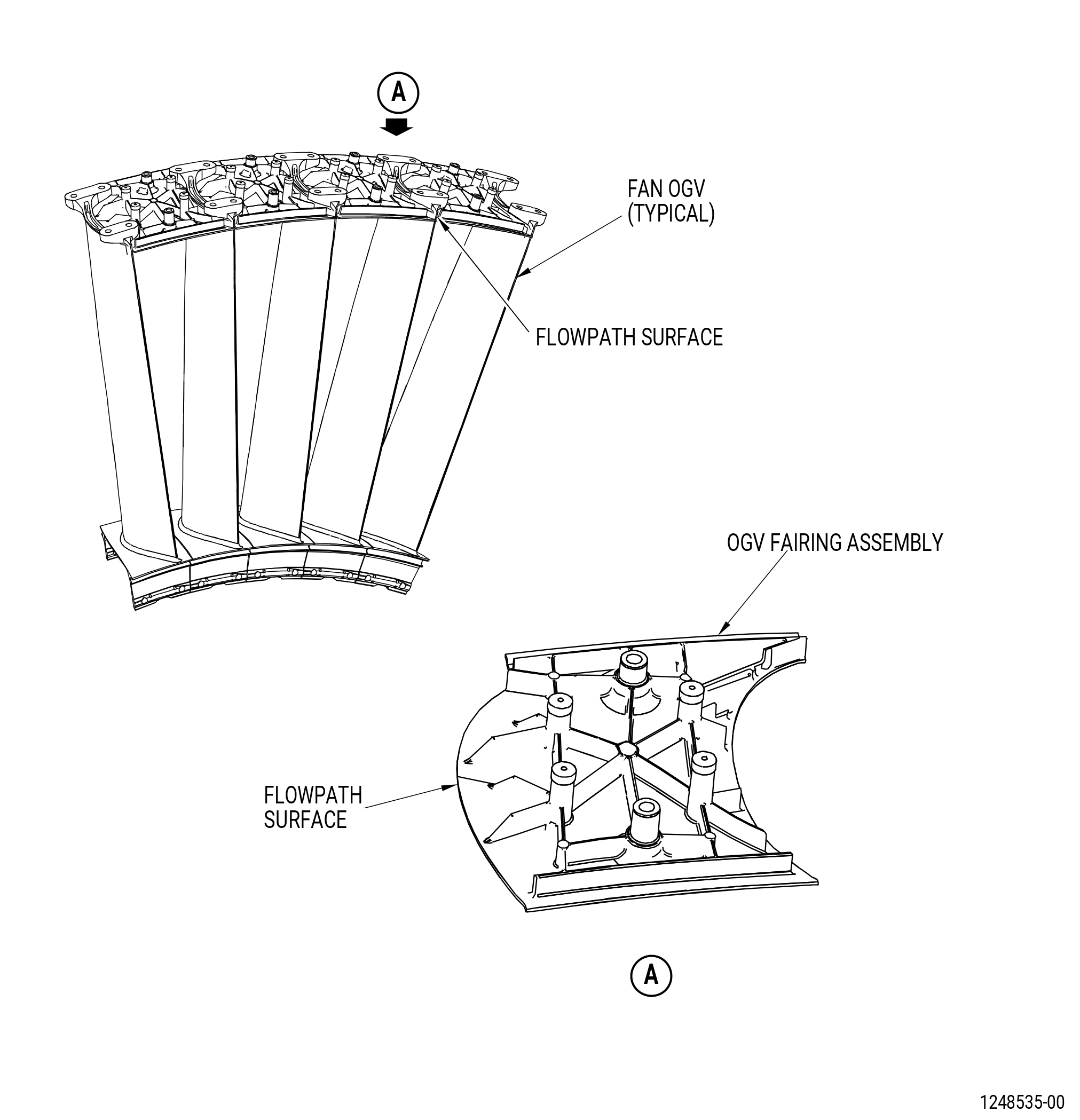
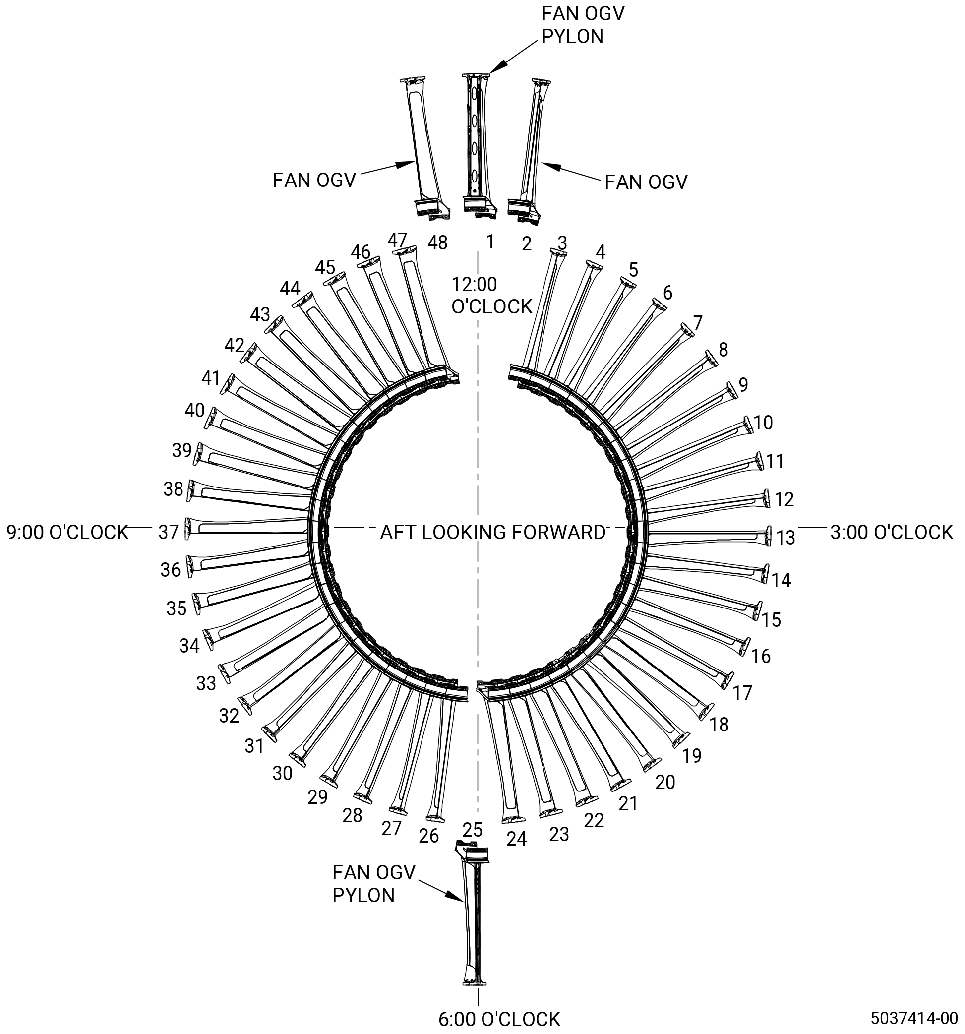
| J. | Do an inspection of each fan OGV fairing assembly (OGV fairing assembly) (84103, 84104, 84105, 84106, 84107, 84108, 84109, 8410A, 8410B, 8410C, 8410D, 8410E, 8410F, 8410G, 8410H, 8410J, 8410P, 8410R, 8410S) on the aft fan case (84100) as follows. Refer to Figure 809. |
| (1) | Missing pieces: |
| Maximum serviceable limit: |
|
| Repair method: |
|
| Subtask 72-00-21-220-023 |
| (2) | Shallow nicks, scratches, and wear on all sufaces: |
| Maximum serviceable limit: |
|
| Repair method: |
|
| Subtask 72-00-21-220-024 |
| (3) | Cracks in all areas of the flowpath surface: |
| Maximum serviceable limit: |
|
| Repair method: |
|
| Subtask 72-00-21-220-084 |
| (4) | Missing RTV in screw holes above screw heads: |
| NOTE: |
|
| Maximum serviceable limit: |
|
| Maximum repairable limit: |
|
| Repair method: |
|
| Subtask 72-00-21-220-025 |
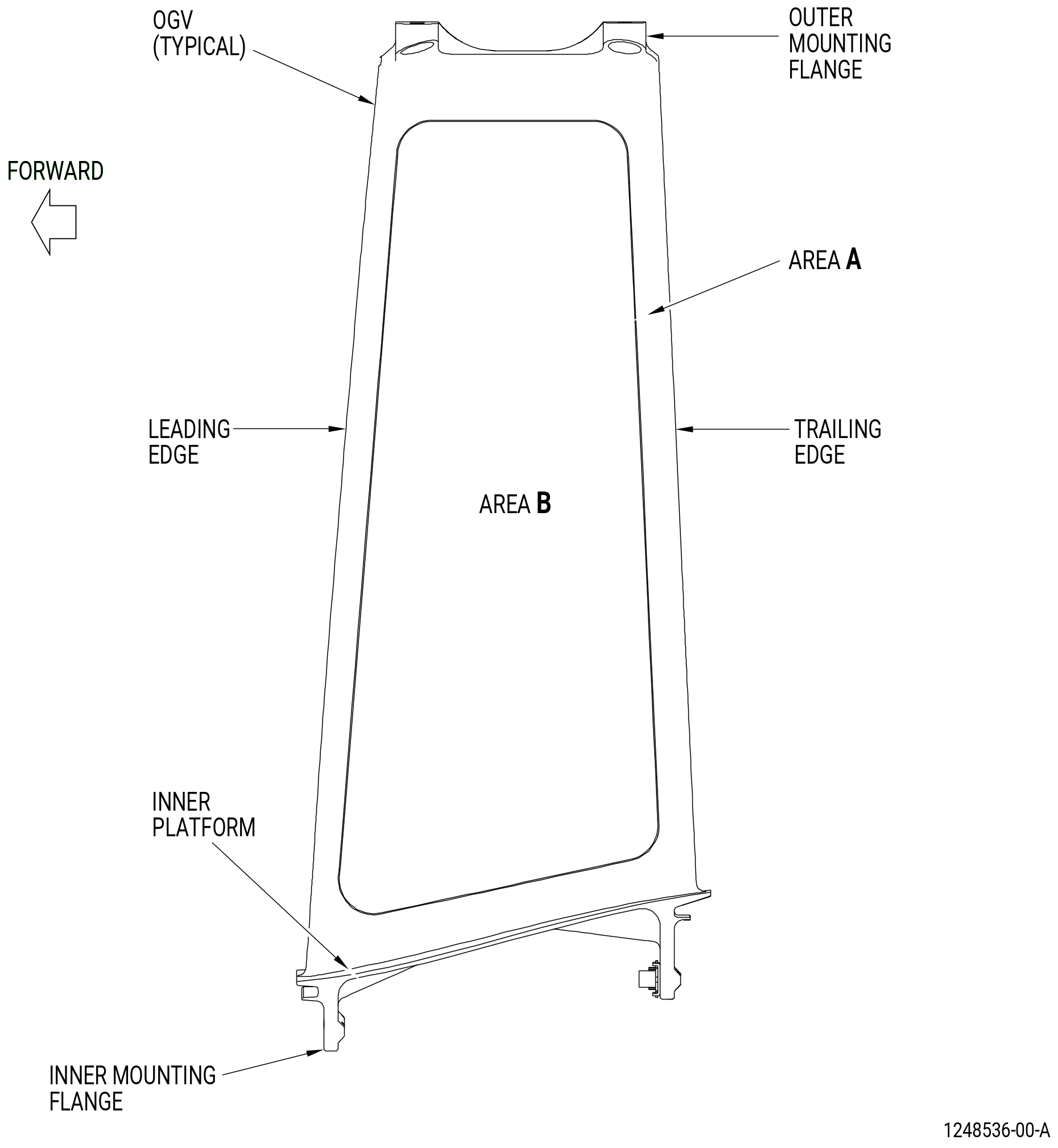
| K. | Do an inspection of the fan outlet guide vanes (OGV) (8400A, 8400C, 8400D, 8400E, 8400F, 8400G, 8400H, 8400J, 8400K, 8400L, 8400M) as follows. Refer to Figure 810. |
| (1) | Cracks: |
| Maximum serviceable limit: |
|
| Repair method: |
|
| Subtask 72-00-21-220-046 |
| (2) | Nicks and scratches (does not include inner and outer mounting flanges or flowpath surfaces of the inner platform): |
| Maximum serviceable limit: |
|
| • |
|
| • |
|
| Repair method: |
|
| Subtask 72-00-21-220-047 |
| (3) | Nicks and scratches on the inner and outer mounting flanges: |
| Maximum serviceable limit: |
|
| Maximum repairable limit: |
|
| Repair method: |
|
| Subtask 72-00-21-220-048 |
| (4) | Nicks and scratches on the flowpath surface of the inner platform: |
| Maximum serviceable limit: |
|
| Maximum repairable limit: |
|
| Repair method: |
|
| Subtask 72-00-21-220-098 |
| (5) | Nut plates, rivets, lock nuts and machine screws (retaining bolts) that are damaged, loose or missing: |
| Maximum serviceable limit: |
|
| Maximum repairable limit: |
|
| Repair method: |
|
| Subtask 72-00-21-220-026 |
| (6) | Dents/distortion (does not include flowpath surfaces of the inner platform): |
| Maximum serviceable limit: |
|
| • |
|
| • |
|
| Repair method: |
|
| Subtask 72-00-21-220-027 |
| (7) | Dents on the flowpath surface of the inner platform: |
| Maximum serviceable limit: |
|
| Maximum repairable limit: |
|
| Repair method: |
|
| Subtask 72-00-21-220-049 |
| (8) | Fretting on the inner mounting flange inner flange face: |
| Maximum serviceable limit: |
|
| Repair method: |
|
| Subtask 72-00-21-220-050 |
| (9) | Missing, disbonded or damaged metal covers on the outer diameter (OD) of the outer mounting flange: |
| Maximum serviceable limit: |
|
| Maximum repairable limit: |
|
| Repair method: |
|
| Subtask 72-00-21-220-072 |
| * * * PRE SB 72-0156( PIP2 Configuration ) |
| (10) | Missing, disbonded or damaged metal covers on the inner diameter (ID) of the inner mounting flange of OGVs 41 thru 9 (numbers in accordance with Figure 811): |
| Maximum serviceable limit: |
|
| Maximum repairable limit: |
|
| Repair method: |
|
| Subtask 72-00-21-220-080 |
| (11) | Missing, disbonded or damaged metal covers on the ID of the inner mounting flange of OGVs 10 thru 40 (numbers in accordance with Figure 811): |
| Maximum serviceable limit: |
|
| Maximum repairable limit: |
|
| Repair method: |
|
| * * * END PRE SB 72-0156( PIP2 Configuration ) |
| Subtask 72-00-21-220-081 |
| * * * SB 72-0417( Elastomer Plug Configuration ) |
| (12) | Missing, disbonded or damaged rubber plug on the ID of the inner mounting flange: |
| Maximum serviceable limit: |
|
| Repair method: |
|
| * * * END SB 72-0417 |
| Subtask 72-00-21-220-085 |
| (13) | Corrosion on trailing edge of the lower OGV pylon: |
| Maximum serviceable limit: |
|
| Repair method: |
|
| (a) | Remove affected nut plate. |
| (b) | Remove the corrosion by blending. Minimum permitted wall thickness after blend is 0.115 inch (2.92 mm). Blend to a smooth contour with surrounding area. Refer to TASK 70-42-00-350-002 (BLENDING AND REMOVAL OF HIGH METAL PROCEDURES). |
| (c) | Do a local touch-up and paint at the repair area with missing paint. Refer to Subtask 72-00-21-220-051 (paragraph 4.K.(13)). |
| (d) | Install the nut plate. Use wet installation method. Refer to TASK 70-13-00-390-001 (RIVETED JOINTS). |
| Subtask 72-00-21-220-051 |
| (14) | Missing paint: |
| Maximum serviceable limit: |
|
| Maximum repairable limit: |
|
| Repair method: |
|
| WARNING: |
|
| WARNING: |
|
| (a) | Solvent wipe the area that has missing paint. Use C04-003 acetone or C04-035 isopropyl alcohol to clean the fan OGV. Refer to TASK 70-46-01-350-030 (MASKING AND CLEANING OF EPOXY AND POLYESTER MATRIX THERMOSETTING COMPOSITE MATERIALS). |
| (b) | Touch-up the area. Apply coating to the area. Refer to TASK 70-43-07-380-007 (CHEMICAL TOUCH-UP SURFACE REFINISHING PROCESS FOR ALUMINUM). |
| 1 | Wipe all unwanted solution. |
| (c) | Apply C03-007 primer, C03-079 primer, C03-085 primer, or C03-100 primer to the chemical touch-up areas to a dry thickness of 0.0002-0.0006 inch (0.005-0.015 mm). Refer to TASK 70-43-22-380-014 (PAINT - EPOXY COATING FOR ALUMINUM AND FERROUS ALLOYS). |
| (d) | Apply C03-119 polyurethane coating to the epoxy primed areas to a dry thickness of 0.001-0.005 inch (0.026-0.12 mm). Refer to TASK 70-43-22-380-014 (PAINT - EPOXY COATING FOR ALUMINUM AND FERROUS ALLOYS). |
| Subtask 72-00-21-220-079 |
| (15) | Missing sealant in the spaces of the OGV platforms (at OGV inner diameter). Refer to Figure 812: |
| Maximum serviceable limit: |
|
| Maximum repairable limit: |
|
| Repair method: |
|
| (a) | Remove all the existing RTV sealant around the OGV platforms and in the seams with a non-metallic spatula. |
| WARNING: |
|
| (b) | Use a clean cloth moistened with C04-035 isopropyl alcohol to clean all surfaces. |
| Subtask 72-00-21-350-001 |
| (c) | Alternative Procedure Available. Apply sealant between the OGV platforms as follows: |
| 1 | The total width of the C01-176 RTV 133 and the space must be approximately 0.500-0.625 inch (12.70-15.88 mm). Make sure that the space width is the same for all locations. |
| WARNING: |
|
| 2 | Apply C01-159 RTV primer to all surfaces where sealant is needed. Let the RTV primer dry for 15 minutes. |
| 3 | Apply C01-176 RTV 133 to the spaces between the OGV platforms. If necessary, use C10-012 tape and a caulking gun to apply the sealant. |
| 4 | Make the contour of the C01-176 RTV 133 flush with, or below, the surface of the OGV platform, and make all changes in the contour smooth. Do no let any of the contour surfaces be irregular. |
| 5 | Let the C01-176 RTV 133 cure according to the manufacturer's instructions. |
| Subtask 72-00-21-350-002 |
| (c).A. | Alternative Procedure. Apply sealant between the OGV platforms as follows: |
| 1 | The total width of the C01-218 adhesive system and the space must be approximately 0.500-0.625 inch (12.70-15.88 mm). Make sure that the space width is the same for all locations. |
| 2 | Apply C01-217 primer to all surfaces where sealant is needed. Let the primer dry for 30 minutes. |
| 3 | Apply C01-218 adhesive system to the spaces between the OGV platforms. If necessary, use C10-012 tape and a caulking gun to apply the sealant. |
| NOTE: |
|
| 4 | Make the contour of the C01-218 adhesive system flush with, or below, the surface of the OGV platform, and make all changes in the contour smooth. Do not let any of the contour surfaces be irregular. |
| 5 | Let the C01-218 adhesive system cure according to the manufacturer's instructions. |