| GENX-1B CLEANING,INSPECTION,AND REPAIR MANUAL | Dated: 02/27/2020 | |
| CIR 72-00-01 , REPAIR 008 | ||
| FAN STATOR MODULE ASSEMBLY - REPAIR - PATCH REPAIR OF DAMAGE TO THE FORWARD FAN CASE TRENCH FILLER PANEL FACESHEET AND HONEYCOMB | ||
| GENX-1B CLEANING,INSPECTION,AND REPAIR MANUAL | Dated: 02/27/2020 | |
| CIR 72-00-01 , REPAIR 008 | ||
| FAN STATOR MODULE ASSEMBLY - REPAIR - PATCH REPAIR OF DAMAGE TO THE FORWARD FAN CASE TRENCH FILLER PANEL FACESHEET AND HONEYCOMB | ||
| * * * FOR ALL |
| TASK 72-00-01-300-806 |
| 1 . | Repair for the Fan Stator Module Assembly. |
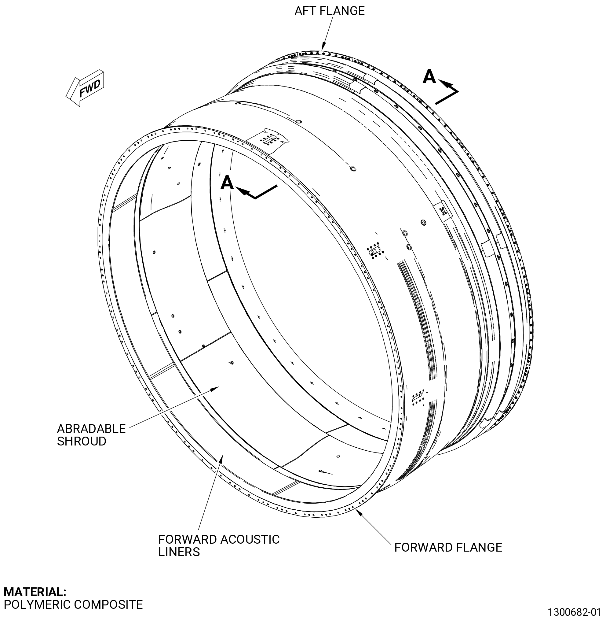
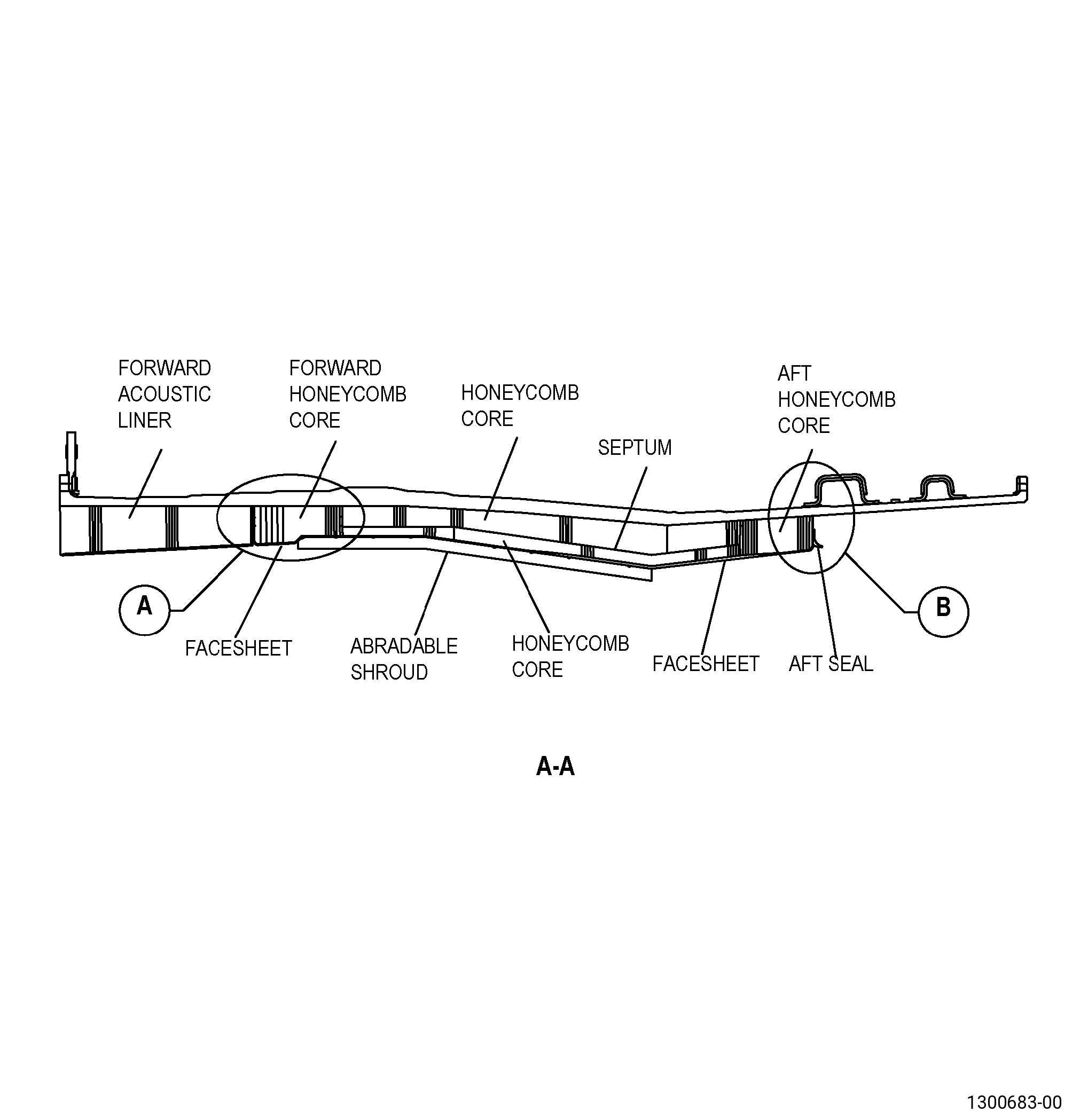
| A. | This procedure gives instructions to repair the fan stator module assembly (forward fan case) by applying abradable material and a wet lay-up to the damaged trench filler panel facesheet (facesheet) and honeycomb areas. Refer to Figure 901. |
| NOTE: |
|
| B. | The following maximum repairable limits apply to this repair: |
| NOTE: |
|
| NOTE: |
|
| (4) | Visual Inspection. |
| (a) | Do an inspection of the forward fan case (83500) for: |
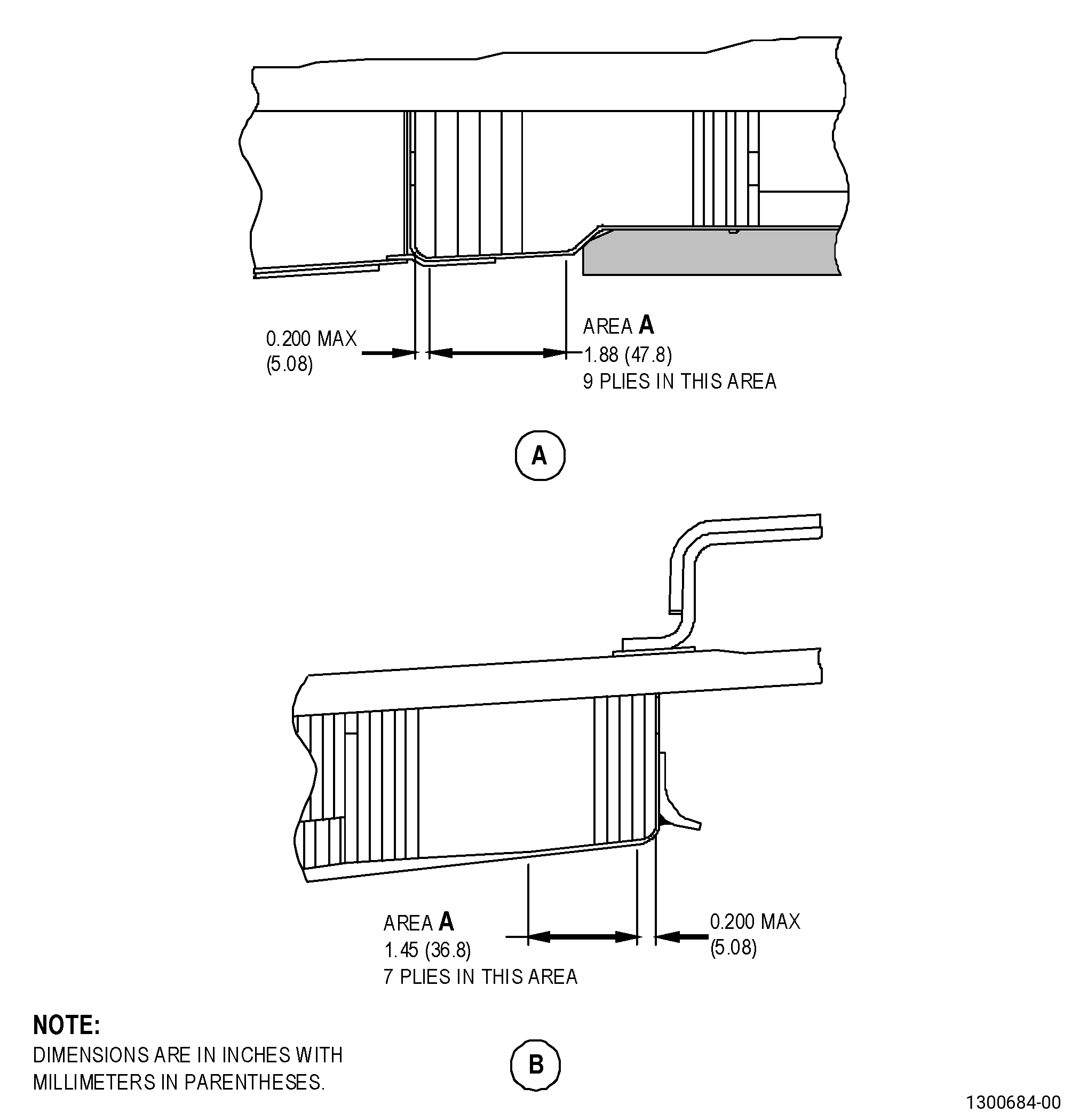
| 8 | Holes and punctures in the trench filler facesheet of area A. Refer to Figure 902. |
| Maximum repairable limit: |
|
| C. | The subsequent table gives a list of the part numbers that are applicable to this repair. All part numbers are applicable to all paragraphs unless specified differently. |
|
|||||||||||||||||||||||
| D. | Proprietary/Complex Process Statement. |
| (1) | None. |
| 2 . | Tools, Equipment, and Materials. |
| NOTE: |
|
| A. | Tools and Equipment. |
| (1) | Special Tools. None. |
| (2) | Standard Tools and Equipment. |
| (3) | Locally Manufactured Tools. |
|
| B. | Consumable Materials. |
|
| C. | Referenced Procedures. |
|
| D. | Expendable Parts. None. |
| E. | SPD Information. None. |
| F. | Special Solutions. None. |
| G. | Test Specimens. None. |
| 3 . | Dimensional Information. |
| Subtask 72-00-01-220-140 |
| A. | Refer to Figure 902 for specified dimensions and locations. |
| NOTE: |
|
| 4 . | Setup Information. |
| None. |
| 5 . | Procedure. |
| Subtask 72-00-01-930-008 |
| A. | If necessary, make the locally manufactured tools that follow: |
| (1) | Make the steel rod. Refer to Figure 908. |
| (2) | Make the Teflon spatula. Refer to Figure 909. |
| Subtask 72-00-01-220-141 |
| B. | Do an inspection of the glass fiber facesheet as follows: |
| (1) | Look for damage on the facesheet. Refer to Figure 903 and do as follows: |
| Subtask 72-00-01-350-093 |
| (a) | Put a mark around the facesheet damaged area. Refer to TASK 70-16-00-350-001 (MARKING PRACTICES), TASK 70-16-02-350-017 (TEMPORARY MARKING), and as follows: |
| 1 | Use a C05-003 marking pen. |
| Subtask 72-00-01-210-002 |
| (2) | Lightly tap the facesheet with the steel rod. Listen to the sound it makes and do as follows: |
| NOTE: |
|
| (a) | If you hear a solid click, there is no disbond or delamination. |
| (b) | If you do not hear a solid click, there is a disbond or delamination. |
| Subtask 72-00-01-350-118 |
| (3) | Put a large mark around the facesheet areas that are disbonded, delaminated, or damaged. Refer to TASK 70-16-00-350-001 (MARKING PRACTICES), TASK 70-16-02-350-017 (TEMPORARY MARKING), and as follows: |
| (a) | Use a C05-003 marking pen. |
| (b) | The mark must be a shape that is easy to cut out. |
| (4) | If the damaged area extends out of area A, you cannot repair the forward fan case with this procedure. Refer to Figure 902. |
| Subtask 72-00-01-350-094 |
| C. | If you found damage in the aft section of the trench filler, pull the aft seal from the repair area as follows: |
| (1) | Use an acrylic spatula to unbond the aft seal around the repair area. |
| (2) | Use an acrylic spatula to remove all the RTV-157 adhesive from the repair area. |
| (3) | Clean the forward fan case repair area. Refer to TASK 70-46-01-350-030 (MASKING AND CLEANING OF EPOXY AND POLYESTER MATRIX THERMOSETTING COMPOSITE MATERIALS) and as follows: |
| (a) | Use Composite Cleaning Method No. 4. |
| Subtask 72-00-01-110-020 |
| WARNING: |
|
| (b) | Use C04-035 isopropyl alcohol. |
| Subtask 72-00-01-350-095 |
| WARNING: |
|
| (4) | Sand the forward fan case with C10-141 abrasive paper to make the repair area smooth and do as follows: |
| (a) | Remove all the remaining RTV-157 adhesive from the repair area. |
| (b) | Make the repair area a constant matte finish. |
| NOTE: |
|
| Subtask 72-00-01-160-016 |
| WARNING: |
|
| (5) | Use clean, dry compressed air that contains no oil to clean the repair area. |
| Subtask 72-00-01-350-096 |
| (6) | Clean the forward fan case repair area. Refer to TASK 70-46-01-350-030 (MASKING AND CLEANING OF EPOXY AND POLYESTER MATRIX THERMOSETTING COMPOSITE MATERIALS) and as follows: |
| (a) | Use Composite Cleaning Method No. 4 or Composite Cleaning Method No. 5. |
| Subtask 72-00-01-350-097 |
| D. | Apply masking to the surfaces around the facesheet repair area. Refer to TASK 70-46-01-350-030 (MASKING AND CLEANING OF EPOXY AND POLYESTER MATRIX THERMOSETTING COMPOSITE MATERIALS) and as follows: |
| (1) | Use Composite Masking Method No. 3. |
| Subtask 72-00-01-350-121 |
| WARNING: |
|
| E. | Cut and remove the damaged and disbonded facesheet material from the forward fan case as follows: |
| WARNING: |
|
| CAUTION: |
|
| (1) | Drill a hole through the facesheet at each corner of the area that you identified in Subtask 72-00-01-350-093 (paragraph 5.B.(3)) to cut out as follows: |
| (a) | The hole must have a minimum diameter of 0.5 inch (13 mm). |
| (2) | Cut along the mark around the area that you will remove as follows: |
| (a) | Use a small, right-angle drive grinder with a small cut-off disk. |
| (3) | Start at a corner and carefully pull the damaged facesheet from the honeycomb. |
| Subtask 72-00-01-350-122 |
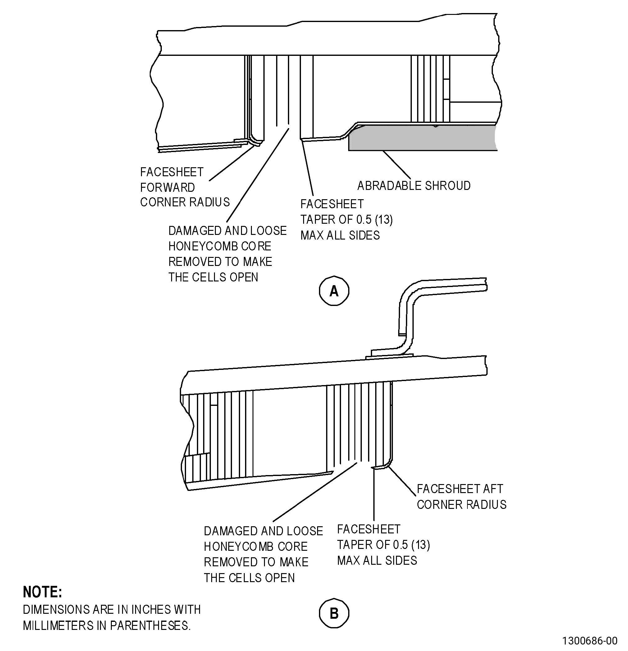
| F. | Remove the loose or damaged honeycomb from the forward fan case. Refer to Figure 904 and as follows: |
| (1) | Remove the loose or damaged honeycomb until the top of the honeycomb cells are open. |
| (2) | If necessary, remove all the temporary patch material in the honeycomb cells. |
| NOTE: |
|
| Subtask 72-00-01-220-142 |
| G. | Do an inspection of the honeycomb cells and the facesheet in the forward fan case repair area as follows: |
| Subtask 72-00-01-360-022 |
| (1) | If necessary, dry the facesheet repair area to remove the liquids. Refer to TASK 70-46-02-360-002 (DRYING OF THERMOSETTING COMPOSITE MATERIALS) and as follows: |
| (a) | Use Visible Liquid Removal - Method 1 (Water) or Visible Liquid Removal - Method 2 (liquid other than water). |
| (b) | After you remove the liquids, continue to dry the repair area as follows: |
| WARNING: |
|
| 1 | Use Absorbed Moisture Removal - Method 3 (Hot Air Dryer) and do as follows: |
| a | Increase the temperature of the repair area to a maximum of 180°F (82°C). |
| b | Keep the temperature of the repair area at a maximum of 180°F (82°C) until you cannot see the liquid. |
| c | Continue to dry the repair area for a minimum of 30 minutes more after you cannot see the liquid. |
| Subtask 72-00-01-350-099 |
| (2) | If there is oil contamination in the honeycomb cells, do as follows: |
| (a) | Clean the honeycomb cells. Refer to TASK 70-46-01-350-030 (MASKING AND CLEANING OF EPOXY AND POLYESTER MATRIX THERMOSETTING COMPOSITE MATERIALS) and as follows: |
| 1 | Use Honeycomb Cleaning Method No. 4. |
| Subtask 72-00-01-110-021 |
| WARNING: |
|
| 2 | Use C04-035 isopropyl alcohol. |
| 3 | Clean the honeycomb to approximately 1.0 inch (25 mm) below the top of the cells. |
| Subtask 72-00-01-350-100 |
| (3) | If there is oil contamination on the facesheet repair area, do as follows: |
| (a) | Clean the forward fan case facesheet repair area. Refer to TASK 70-46-01-350-030 (MASKING AND CLEANING OF EPOXY AND POLYESTER MATRIX THERMOSETTING COMPOSITE MATERIALS) and as follows: |
| 1 | Use Composite Cleaning Method No. 4. |
| Subtask 72-00-01-110-022 |
| WARNING: |
|
| 2 | Use C04-035 isopropyl alcohol. |
| Subtask 72-00-01-140-014 |
| WARNING: |
|
| H. | Sand the forward fan case facesheet to make a taper in the glass fiber facesheet. Refer to Figure 904 and as follows: |
| (1) | If the taper extends out of area A, you cannot repair the facesheet with this procedure. |
| (2) | Use a sanding disk of 1.0 inch (25 mm) in diameter in a small right-angle drive grinder. |
| (3) | Make the taper 0.5 inch (13 mm) in width. |
| Subtask 72-00-01-350-102 |
| WARNING: |
|
| CAUTION: |
|
| I. | Prepare the surface of the remaining glass fiber facesheet as follows: |
| (1) | Manually sand the surface until the surface has a constant matte finish. |
| NOTE: |
|
| (2) | Use C10-141 abrasive paper. |
| Subtask 72-00-01-160-018 |
| WARNING: |
|
| J. | Use clean, dry, compressed air that contains no oil to clean the dust from the forward fan case repair area. |
| Subtask 72-00-01-350-103 |
| K. | Clean the forward fan case facesheet repair area. Refer to TASK 70-46-01-350-030 (MASKING AND CLEANING OF EPOXY AND POLYESTER MATRIX THERMOSETTING COMPOSITE MATERIALS) and as follows: |
| (1) | Use Composite Cleaning Method No. 5. |
| Subtask 72-00-01-110-023 |
| WARNING: |
|
| (2) | Use C04-035 isopropyl alcohol. |
| Subtask 72-00-01-350-104 |
| L. | Apply masking to the forward fan case facesheet repair area. Refer to TASK 70-46-01-350-030 (MASKING AND CLEANING OF EPOXY AND POLYESTER MATRIX THERMOSETTING COMPOSITE MATERIALS) and as follows: |
| (1) | Use Composite Masking Method No. 4. |
| (2) | Apply masking to the facesheet repair area to protect it until you apply the C01-161 abradable material. |
| Subtask 72-00-01-360-023 |
| WARNING: |
|
| WARNING: |
|
| WARNING: |
|
| WARNING: |
|
| CAUTION: |
|
| M. | Mix the C01-161 abradable material as follows: |
| (1) | Alternative Procedure Available. Prepare the C01-161 abradable material found in the 1.5 pounds (680 grams), equal to 1 pint (473 milliliters), kit as follows: |
| NOTE: |
|
| (a) | Put the resin and hardener in a clean, grease-free metal plate. Keep the resin and hardener separate from each other. |
| (b) | Mix the resin and hardener separately with spatulas. Make sure that each part is fully mixed before you mix them together. |
| (c) | Mix the resin and hardener together for approximately 4-5 minutes until you see no streaks of the two components. |
| NOTE: |
|
| (d) | If necessary, increase the pot life of the C01-161 abradable material by applying a thin layer of the mixed adhesive on a metal surface until it is used. |
| Subtask 72-00-01-360-025 |
| (1).A. | Alternative Procedure. Prepare the C01-161 abradable material found in the 6.0 oz (170 g) adhesive cartridge. Refer to Figure 910 and as follows: |
| (a) | Remove the cinch tape from the cartridge. |
| (b) | Pull the dasher rod up to the threaded neck end of the cartridge. |
| NOTE: |
|
| (c) | Push the cartridge sides in the foil to cause damage to the foil barrier. |
| (d) | Push the dasher rod to the plunger end of the cartridge to take out the damaged foil barrier. |
| (e) | Put the dasher rod on the spindle of the drive mixer. |
| (f) | Turn the drive mixer on. |
| (g) | Hold the cartridge body and push and pull the cartridge body up and down for 4 minutes and do as follows: |
| 1 | Make sure that the dasher touches the two ends of the cartridge when it operates through its full movement. |
| 2 | Complete a minimum of 120 full movements during 4 minutes. |
| (h) | Stop the drive mixer. |
| (i) | Remove the bottom cap. |
| (j) | Push the dasher rod to the plunger end of the cartridge and hold the cartridge tightly at the plunger end. |
| (k) | Turn the dasher rod counterclockwise to disconnect it from the mixing dasher. |
| (l) | Remove the dasher rod from the cartridge. |
| (m) | Put the nozzle into the neck end of the cartridge. |
| (n) | Put the cartridge into a dispensing gun. |
| (o) | Make sure that you remove the material from the cartridge in 2 minutes or less after you mixed it. |
| NOTE: |
|
| Subtask 72-00-01-360-034 |
| WARNING: |
|
| WARNING: |
|
| CAUTION: |
|
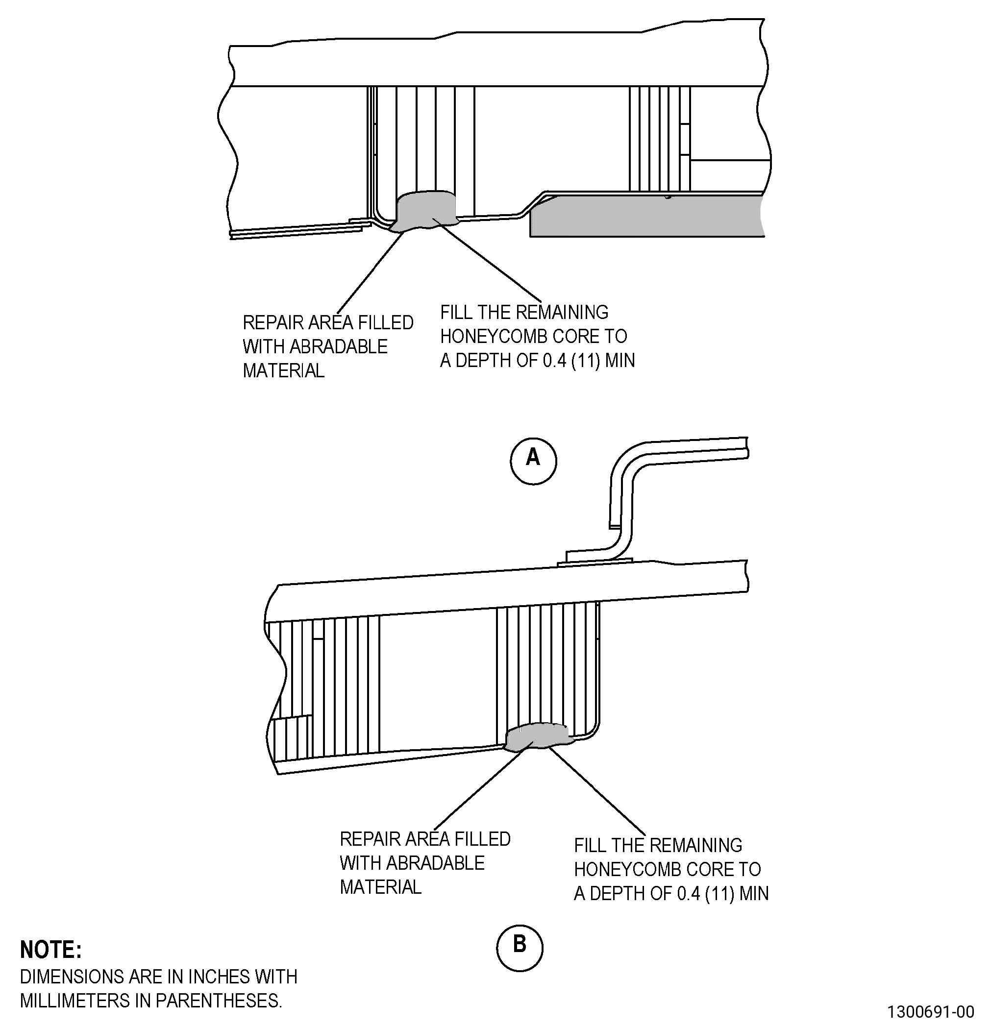
| N. | Put the C01-161 abradable material in the honeycomb cells. Refer to Figure 905 and as follows: |
| (1) | Remove the masking that you applied in Subtask 72-00-01-350-104 (paragraph 5.L.) for the protection of the honeycomb cells. Keep the masking around the repair area to prevent spills. |
| (2) | Use a C10-108 brush and the Teflon spatula to push the C01-161 abradable material to the top of all the honeycomb cells. |
| (3) | Fill the cells to approximately 0.4 inch (10 mm) in depth. |
| (4) | Use the Teflon spatula to make the C01-161 abradable material level or a small amount above the adjacent facesheet surfaces. |
| Subtask 72-00-01-110-024 |
| O. | Remove the unwanted abradable material from adjacent facesheet surfaces as follows: |
| WARNING: |
|
| (1) | Use a C10-182 cleaning cloth moist with C04-035 isopropyl alcohol. |
| Subtask 72-00-01-220-143 |
| P. | Do an inspection of the C01-161 abradable material on the forward fan case repair area as follows: |
| (1) | If the C01-161 abradable material moves, use the Teflon spatula to make the C01-161 abradable material smooth and level with the adjacent facesheet surfaces. |
| Subtask 72-00-01-360-026 |
| WARNING: |
|
| Q. | Cure the C01-161 abradable material in the forward fan case repair area. Refer to SAE ARP 5144 Heat Application for Thermosetting Resin Curing, and as follows: |
| (1) | Let the C01-161 abradable material cure for a minimum of 24 hours at a temperature range of 77 to 100°F (25 to 38°C) and do as follows: |
| (a) | If the ambient temperature is less than 77°F (25°C), you can use heat lamps or a thermal blanket to increase the temperature to 77°F (25°C) as follows: |
| 1 | Use a thermocouple to monitor the temperature. |
| 2 | Keep the temperature at a range of 77 to 100°F (25 to 38°C). |
| (b) | If the ambient temperature is above 77°F (25°C), do not increase the temperature. |
| NOTE: |
|
| Subtask 72-00-01-350-107 |
| WARNING: |
|
| R. | Sand the C01-161 abradable material on the honeycomb cells to make it smooth as follows: |
| (1) | Use C10-141 abrasive paper. |
| (2) | Make sure that the C01-161 abradable material is 0.000-0.005 inch (0.00-0.12 mm) above the adjacent facesheet surfaces. |
| Subtask 72-00-01-160-019 |
| WARNING: |
|
| S. | Use clean, dry, compressed air that contains no oil to clean the dust from the forward fan case repair area. |
| Subtask 72-00-01-350-108 |
| T. | Clean the forward fan case repair area. Refer to TASK 70-46-01-350-030 (MASKING AND CLEANING OF EPOXY AND POLYESTER MATRIX THERMOSETTING COMPOSITE MATERIALS) and as follows: |
| (1) | Use Composite Cleaning Method No. 4 or Composite Cleaning Method No. 5. |
| Subtask 72-00-01-110-025 |
| WARNING: |
|
| (2) | Use C04-035 isopropyl alcohol. |
| Subtask 72-00-01-220-144 |
| U. | Do an inspection of the surface of the C01-161 abradable material repair area as follows: |
| (1) | Make sure that the repair area has the same contour as the adjacent facesheet surfaces. |
| (2) | If the repaired area of the C01-161 abradable material is below the contour of the facesheet, do Subtask 72-00-01-360-023 (paragraph 5.M.) thru Subtask 72-00-01-220-144 (paragraph 5.U.) again. |
| (3) | If the surface of the C01-161 abradable material has voids more than 0.125 inch (3.18 mm) in width, do as follows: |
| (a) | Fill the voids with the C01-161 abradable material. Do Subtask 72-00-01-360-023 (paragraph 5.M.) thru Subtask 72-00-01-220-144 (paragraph 5.U.). |
| Subtask 72-00-01-350-109 |
| V. | Apply masking to the forward fan case repair areas. Refer to TASK 70-46-01-350-030 (MASKING AND CLEANING OF EPOXY AND POLYESTER MATRIX THERMOSETTING COMPOSITE MATERIALS) and as follows: |
| (1) | Use Composite Masking Method No. 4. |
| (2) | Apply the masking to protect the repair areas until you apply the wet lay-up. |
| NOTE: |
|
| Subtask 72-00-01-350-110 |
| W. | Make a wet lay-up to use it a as cover for the forward fan case repair area as follows: |
| (1) | If necessary, remove abradable shroud to correctly install the wet lay-up. Refer to TASK 72-00-01-300-801 (72-00-01, REPAIR 003) and Figure 906. |
| WARNING: |
|
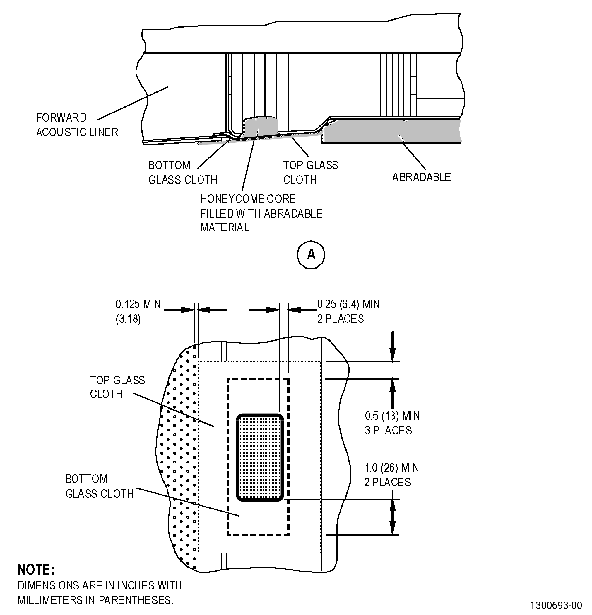
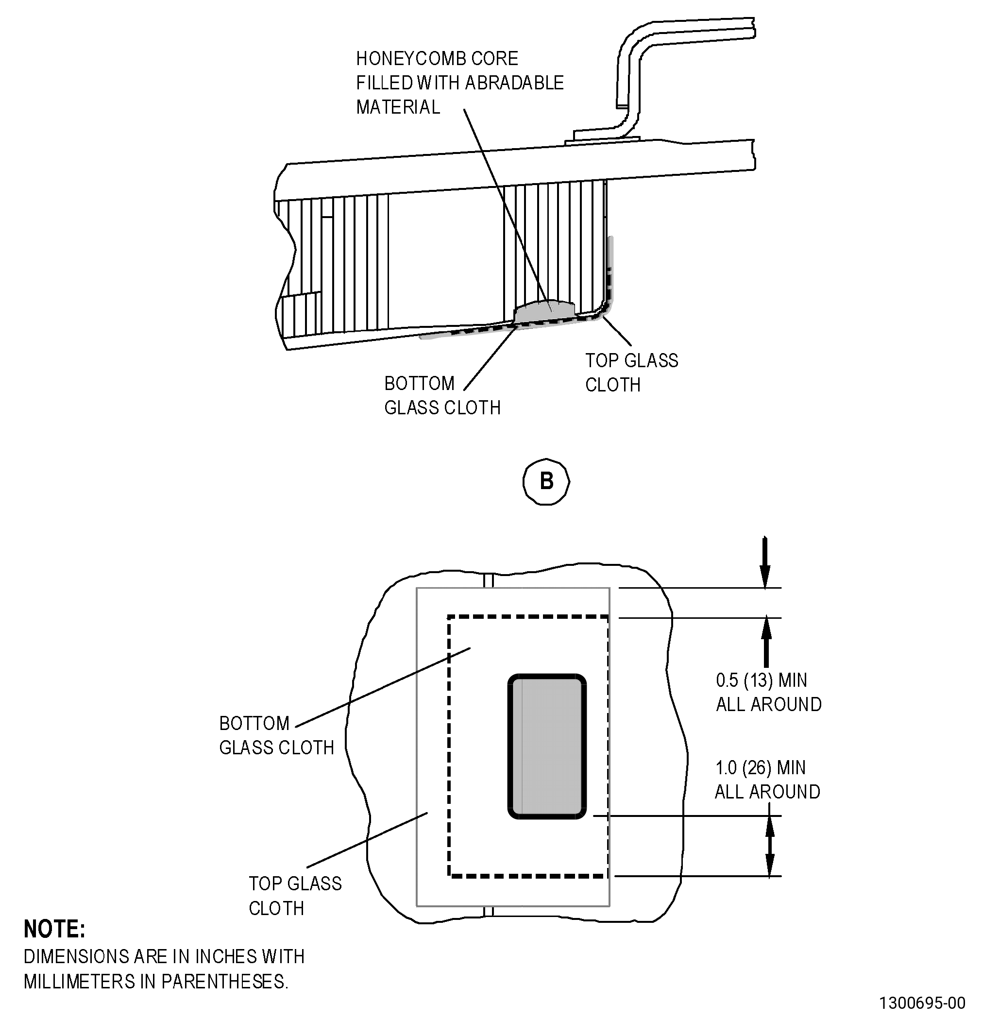
| (2) | Cut two pieces of C10-122 glass cloth larger than the repair area on all sides. Refer to Figure 906 and as follows: |
| (a) | For the forward repair area, the width of the cloths must be approximately 2.0 inches (51 mm) to make sure that you can install them between the abradable shroud and the forward acoustic liner. |
| (b) | For the aft repair area, the bottom C10-122 glass cloth must be smaller on all sides than the top C10-122 glass cloth. |
| Subtask 72-00-01-360-027 |
| WARNING: |
|
| WARNING: |
|
| CAUTION: |
|
| (3) | Make an estimate of the quantity of C01-017 liquid epoxy resin that you will use. |
| (4) | Mix the C01-017 liquid epoxy resin in a clean, metal container or paper container that has no wax. |
| (5) | Mix the adhesive materials as follows: |
| (a) | C01-017 liquid epoxy resin - 100 parts by weight. |
| WARNING: |
|
| (b) | C01-024 catalyst - 12 parts by weight. |
| (c) | C03-029 carbon black - 2.7 parts by weight. |
| (d) | Mix the adhesive materials until there are no streaks. |
| NOTE: |
|
| (6) | Prepare the two pieces of C10-122 glass cloth as follows: |
| (a) | Put a sheet of C10-142 polyester film on a work bench or table. |
| (b) | Apply a small quantity of adhesive on the C10-142 polyester film and do as follows: |
| 1 | Use a clean, Teflon spatula to make the adhesive layer of approximately 0.010 inch (0.25 mm) in thickness. |
| (c) | Put one C10-122 glass cloth on the adhesive and the C10-142 polyester film. |
| (d) | Put a second piece of C10-142 polyester film on top of the C10-122 glass cloth and the adhesive. |
| (e) | Use the Teflon spatula to remove all the caught air and the unwanted liquid adhesive. |
| (f) | Do Subtask 72-00-01-360-027 (paragraph 5.W.(6)) again for the second C10-122 glass cloth. |
| Subtask 72-00-01-360-028 |
| X. | Apply the C10-122 glass cloth and adhesive layer on the forward fan case repair area. Refer to Figure 906 and as follows: |
| (1) | Apply a layer of adhesive approximately 0.010 inch (0.25 mm) in thickness on the repair area that you sanded as follows: |
| (a) | Use a new, clean C10-108 brush to apply the adhesive. |
| (b) | Use the Teflon spatula to remove all the caught air and make the adhesive smooth. |
| (2) | Apply the bottom C10-122 glass cloth and the adhesive to the repair area as follows: |
| Subtask 72-00-01-350-112 |
| (a) | Remove the polyester film from one side of the bottom C10-122 glass cloth as follows: |
| WARNING: |
|
| 1 | Use a razor knife to separate the C10-142 polyester film layers from around the edges. |
| Subtask 72-00-01-360-029 |
| (b) | Put the bottom C10-122 glass cloth and adhesive on the repair area as follows: |
| 1 | Put the bottom C10-122 glass cloth and adhesive in position to make an overlap of the repair area on all sides. |
| 2 | Remove the top piece of polyester film from the bottom C10-122 glass cloth. |
| (3) | Apply the top C10-122 glass cloth and adhesive to the repair area as follows: |
| Subtask 72-00-01-350-113 |
| (a) | Remove the polyester film from one side of the top C10-122 glass cloth as follows: |
| WARNING: |
|
| 1 | Use a razor knife to separate the C10-122 glass cloth layers from around the edges. |
| Subtask 72-00-01-360-030 |
| (b) | Put the top C10-122 glass cloth and adhesive on the repair area as follows: |
| 1 | Put the top C10-122 glass cloth and adhesive in position to make an overlap of the bottom C10-122 glass cloth. |
| 2 | Remove the top piece of polyester film from the top C10-122 glass cloth. |
| (c) | Make a vacuum bag to put around the repair area. Refer to TASK 70-46-03-360-003 (VACUUM BAGGING OF THERMOSETTING COMPOSITE REPAIRS) and as follows: |
| 1 | Use Bagging Method 1. |
| 2 | If necessary, use C10-136 tape to cover the perforation holes of the forward acoustic liner located under the vacuum bag. |
| 3 | Peel plies, edge breather cloths, caul plates, and heat blankets are not necessary. |
| 4 | Let it cure for 24 hours at a room temperature of 65 to 85°F (18 to 29°C). |
| Subtask 72-00-01-350-114 |
| Y. | Remove the vacuum bag and all the masking from the repair area. Keep only the masking around the abradable repair area to give protection to the forward fan case from spills and drips. |
| Subtask 72-00-01-350-115 |
| WARNING: |
|
| Z. | Sand the forward fan case repair area to get a smooth matte finish as follows: |
| NOTE: |
|
| (1) | Use C10-141 abrasive paper to make the repair area have a smooth transition to adjacent contour. |
| Subtask 72-00-01-160-020 |
| WARNING: |
|
| AA. | Use clean, dry, compressed air that contains no oil to remove the dust from the forward fan case repair area. |
| Subtask 72-00-01-350-116 |
| AB. | Clean the forward fan case repair area. Refer to TASK 70-46-01-350-030 (MASKING AND CLEANING OF EPOXY AND POLYESTER MATRIX THERMOSETTING COMPOSITE MATERIALS) and as follows: |
| (1) | Use Composite Cleaning Method No. 4 or Composite Cleaning Method No. 5. |
| Subtask 72-00-01-220-145 |
| AC. | Do an inspection of the facesheet repair area. Refer to Figure 906 and as follows: |
| (1) | Make sure that the repair area has a smooth transition to adjacent contour. |
| Subtask 72-00-01-360-031 |
| WARNING: |
|
| WARNING: |
|
| CAUTION: |
|
| (2) | If necessary, use C01-155 paste adhesive to fill the surfaces where more thickness is necessary as follows: |
| (a) | Prepare the C01-155 paste adhesive as follows: |
| 1 | Make an estimate of the quantity of the C01-155 paste adhesive that you will use. |
| 2 | Use a clean metal or paper container that has no wax. |
| 3 | Mix each component in the ratio that follows: |
| a | Part A (adhesive) - 100 parts by weight. |
| b | Part B (catalyst) - 17 parts by weight. |
| 4 | Do not mix more adhesive than you can use in 90 minutes. The mixed C01-155 paste adhesive can be used until 90 minutes after the mixing procedure. |
| 5 | Mix the adhesive components until you cannot see streaks of the components. |
| NOTE: |
|
| (b) | Apply the C01-155 paste adhesive as follows: |
| 1 | Use a new and clean C10-108 brush to fill the surfaces where more thickness is necessary. |
| 2 | Apply a layer of C10-133 FEP film on the facesheet repair area. |
| 3 | Use the Teflon spatula to rub the C10-133 FEP film to make the repair area smooth. |
| 4 | Use a clean C10-182 cleaning cloth to remove the unwanted resin. |
| WARNING: |
|
| (c) | Let the mixed adhesive cure. Refer to SAE ARP 5144, Heat Application for Thermosetting Resin Curing, and as follows: |
| NOTE: |
|
| 1 | Let the mixed adhesive cure for 5-7 days at a minimum temperature of 65°F (18°C). |
| (d) | Do Subtask 72-00-01-350-115 (paragraph 5.Z.) thru Subtask 72-00-01-220-145 (paragraph 5.AC.) again. |
| Subtask 72-00-01-220-146 |
| (3) | Do an inspection of the forward fan case repair area. Refer to Subtask 72-00-01-220-141 (paragraph 5.B.) and as follows: |
| (a) | If you find disbonds or delaminations, do the repair procedure again. |
| Subtask 72-00-01-360-032 |
| AD. | If necessary, bond the aft seal in its original position. Refer to Figure 907 and as follows: |
| Subtask 72-00-01-350-117 |
| (1) | Clean the aft seal bond area. Refer to TASK 70-46-01-350-030 (MASKING AND CLEANING OF EPOXY AND POLYESTER MATRIX THERMOSETTING COMPOSITE MATERIALS) and as follows: |
| (a) | Use Composite Cleaning Method No. 4 or Composite Cleaning Method No. 5. |
| Subtask 72-00-01-360-033 |
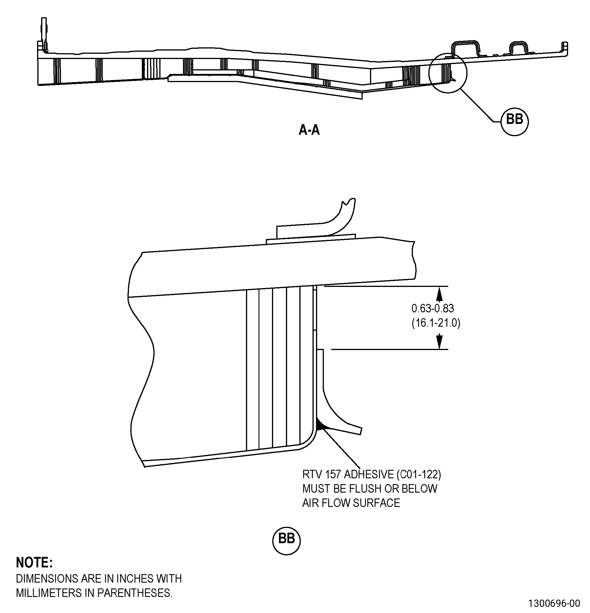
| (2) | Apply C01-122 RTV-157 adhesive to the surfaces of the facesheet and the aft seal that you will bond. |
| (3) | Push the aft seal against the facesheet. |
| (4) | Use C10-136 tape to make sure that the bonded surfaces are correctly adjusted. |
| (5) | Remove the unwanted adhesive. Adhesive must be flush or below the air flow surface. |
| (6) | Let the C01-122 RTV-157 adhesive cure at a minimum ambient temperature of 65°F (18°C) for 24 hours. |
| Subtask 72-00-01-350-119 |
| AE. | If the polysulfide coating was removed or damaged during the repair, apply it. Refer to TASK 72-00-01-300-805 (72-00-01, REPAIR 007). |
| Subtask 72-00-01-350-120 |
| AF. | If necessary, apply the abradable shroud. Refer to TASK 72-00-01-300-801 (72-00-01, REPAIR 003). |