| GENX-1B CLEANING,INSPECTION,AND REPAIR MANUAL | Dated: 02/01/2022 | |
| CIR 72-21-99 , INSPECTION 001 | ||
| STATOR/AFT FAN CASE ASSEMBLY HARDWARE - INSPECTION | ||
| GENX-1B CLEANING,INSPECTION,AND REPAIR MANUAL | Dated: 02/01/2022 | |
| CIR 72-21-99 , INSPECTION 001 | ||
| STATOR/AFT FAN CASE ASSEMBLY HARDWARE - INSPECTION | ||
| * * * FOR ALL |
| TASK 72-21-99-200-801 |
| 1 . | General. |
| A. | This procedure gives instructions to do an inspection of the stator/aft fan case assembly hardware as follows: |
| (1) | Bolts: |
| • |
|
| • |
|
| • |
|
| • |
|
|
|||||||||||||||||||||||||||||||||||||||||||||||||||||||||||||||
| (2) | Fillet fairings: |
|
||||||||||||||||||||||||
| (3) | Flat washers: |
|
||||||||||||||||||||||||||||||||||||||||||
| • |
|
| • |
|
| • |
|
| (4) | OGV panels: |
|
||||||||||||||||||||||||
| (5) | Screws: |
|
|||||||||||||||||||||||||||||||||||||
| (6) | Self-locking nuts: |
|
||||||||||||||||||||||||||||||||||||||||||||||||||
| • |
|
| • |
|
| (7) | Shims: |
| • |
|
| • |
|
|
||||||||||||||||||||||||||||||||||||||||||||||||||||||||||||||||||||||||||||
| (8) | Additional hardware: |
| • |
|
| • |
|
| • |
|
| • |
|
| • |
|
| • |
|
| • |
|
| • |
|
| • |
|
| • |
|
| • |
|
| • |
|
| • |
|
| • |
|
| • |
|
| • |
|
| • |
|
| • |
|
| • |
|
| • |
|
| • |
|
| • |
|
| • |
|
| • |
|
| • |
|
| • |
|
| 2 . | Tools, Equipment, and Materials. |
| NOTE: |
|
| A. | Tools and Equipment. |
| (1) | Special Tools. None. |
| (2) | Standard Tools and Equipment. None. |
| (3) | Locally Manufactured Tools. None. |
| B. | Consumable Materials. |
|
| C. | Referenced Procedures. |
| D. | Expendable Parts. None. |
| 3 . | Specific Inspection Procedure. |
| Subtask 72-21-99-230-001 |
| A. | Do a Class A fluorescent penetrant inspection on the vapor barrier, fan cowl PDOS brackets, lower extension support, upper alignment guide, with Class A acceptability limits. Refer to TASK 70-32-02-230-001 (FLUORESCENT PENETRANT INSPECTION). |
| Subtask 72-21-99-230-002 |
| B. | Do a Class A fluorescent penetrant inspection on the fan bootstrap brackets, cowl support brackets, ground handling mounts upper, and lower firewalls. Refer to TASK 70-32-02-230-001 (FLUORESCENT PENETRANT INSPECTION). |
| NOTE: |
|
| Subtask 72-21-99-230-003 |
| C. | Do a Class B fluorescent penetrant inspection on the weld zones of the FADEC support brackets, lower guide brackets, oil tube support bracket. Refer to TASK 70-32-02-230-001 (FLUORESCENT PENETRANT INSPECTION). |
| 4 . | Post Inspection Procedure. |
| Subtask 72-21-99-360-001 |
| WARNING: |
|
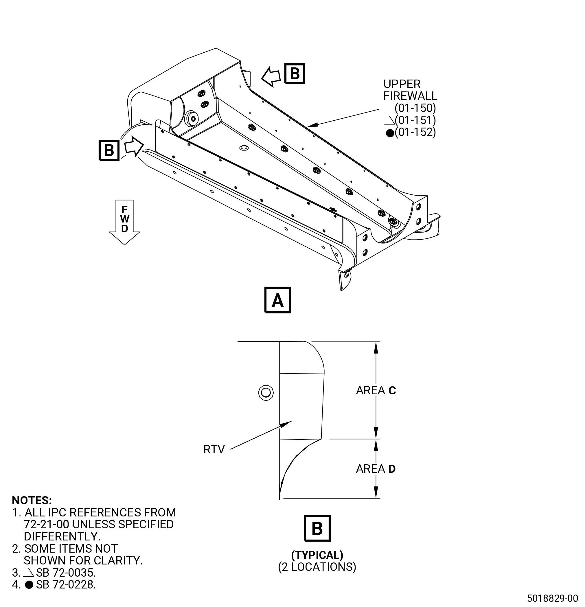
| A. | Apply C01-007 RTV 106 to the upper firewall (01-151 , 72-21-00) (SIN 84401) or (01-152 , 72-21-00) (SIN 84401). Refer to Figure 806 and do as follows: |
| NOTE: |
|
| Subtask 72-21-99-110-021 |
| WARNING: |
|
| (1) | Use C04-035 isopropyl alcohol or equivalent to clean area C and area D of the upper firewall. Refer to TASK 70-21-23-110-053 (CLEANING METHOD NO. 23 - HAND-WIPE DEGREASING). |
| Subtask 72-21-99-380-001 |
| (2) | Apply C01-159 primer to area C and area D. |
| Subtask 72-21-99-360-002 |
| (3) | Fill area C and area D with C01-007 RTV 106 to get a smooth transition. |
| (4) | Do Subtask 72-21-99-110-021 (paragraph 4.A.(1)) thru Subtask 72-21-99-360-002 (paragraph 4.A.(3)) again on the other side of the upper firewall. |
| Subtask 72-21-99-360-003 |
| WARNING: |
|
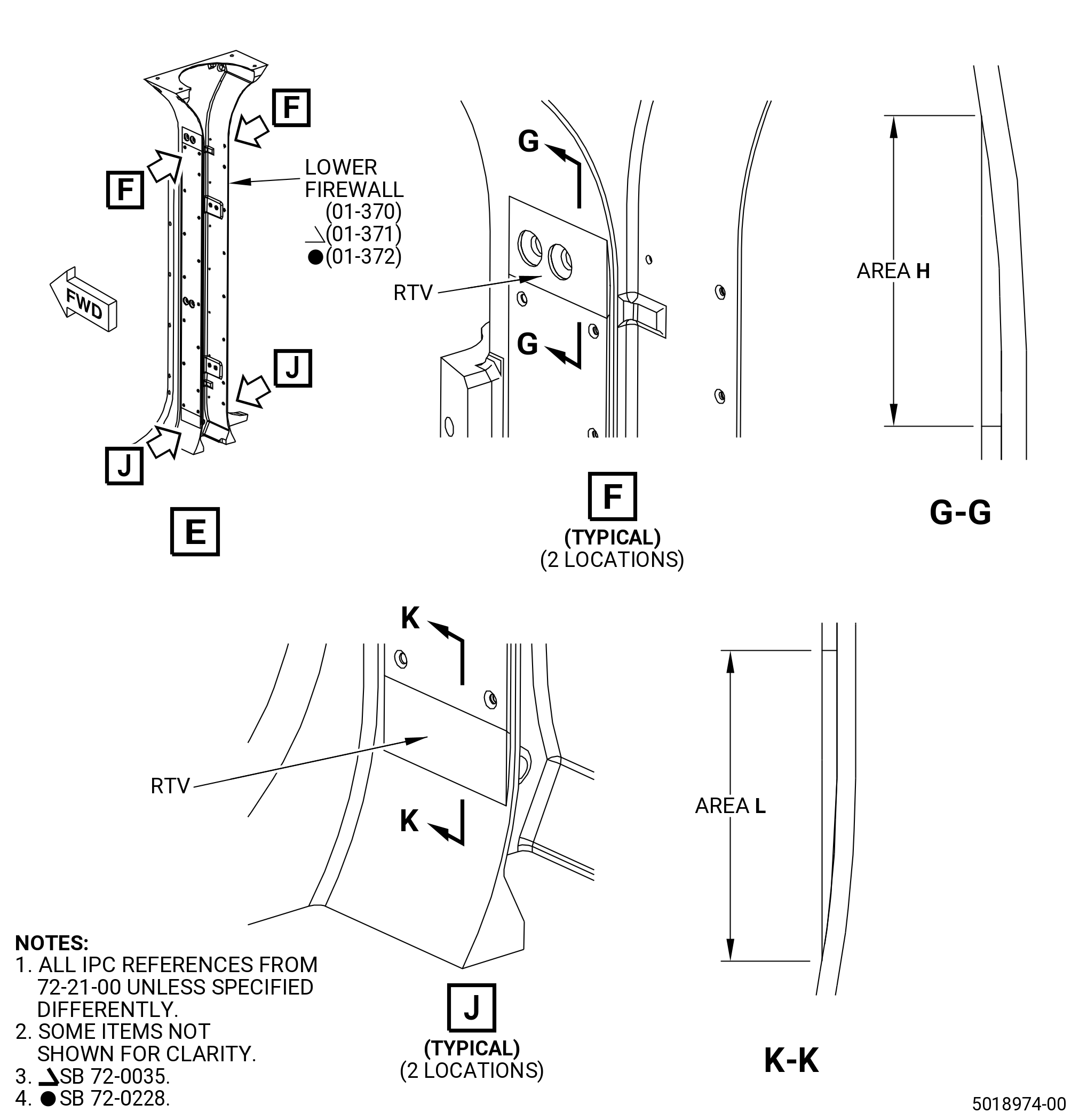
| B. | Apply C01-007 RTV 106 to the lower firewall (01-371 , 72-21-00) (SIN 84501) or (01-372 , 72-21-00) (SIN 84501). Refer to Figure 806 and do as follows: |
| NOTE: |
|
| Subtask 72-21-99-110-022 |
| WARNING: |
|
| (1) | Use C04-035 isopropyl alcohol or equivalent to clean area H and area L of the lower firewall. Refer to TASK 70-21-23-110-053 (CLEANING METHOD NO. 23 - HAND-WIPE DEGREASING). |
| Subtask 72-21-99-380-002 |
| (2) | Apply C01-159 primer to area H and area L. |
| Subtask 72-21-99-360-004 |
| (3) | Fill area H and area L with C01-007 RTV 106 to get a smooth transition. |
| (4) | Do Subtask 72-21-99-110-022 (paragraph 4.B.(1)) thru Subtask 72-21-99-360-004 (paragraph 4.B.(3)) again on the other side of the lower firewall. |
| 5 . | Visual Inspection. |
| Subtask 72-21-99-220-001 |
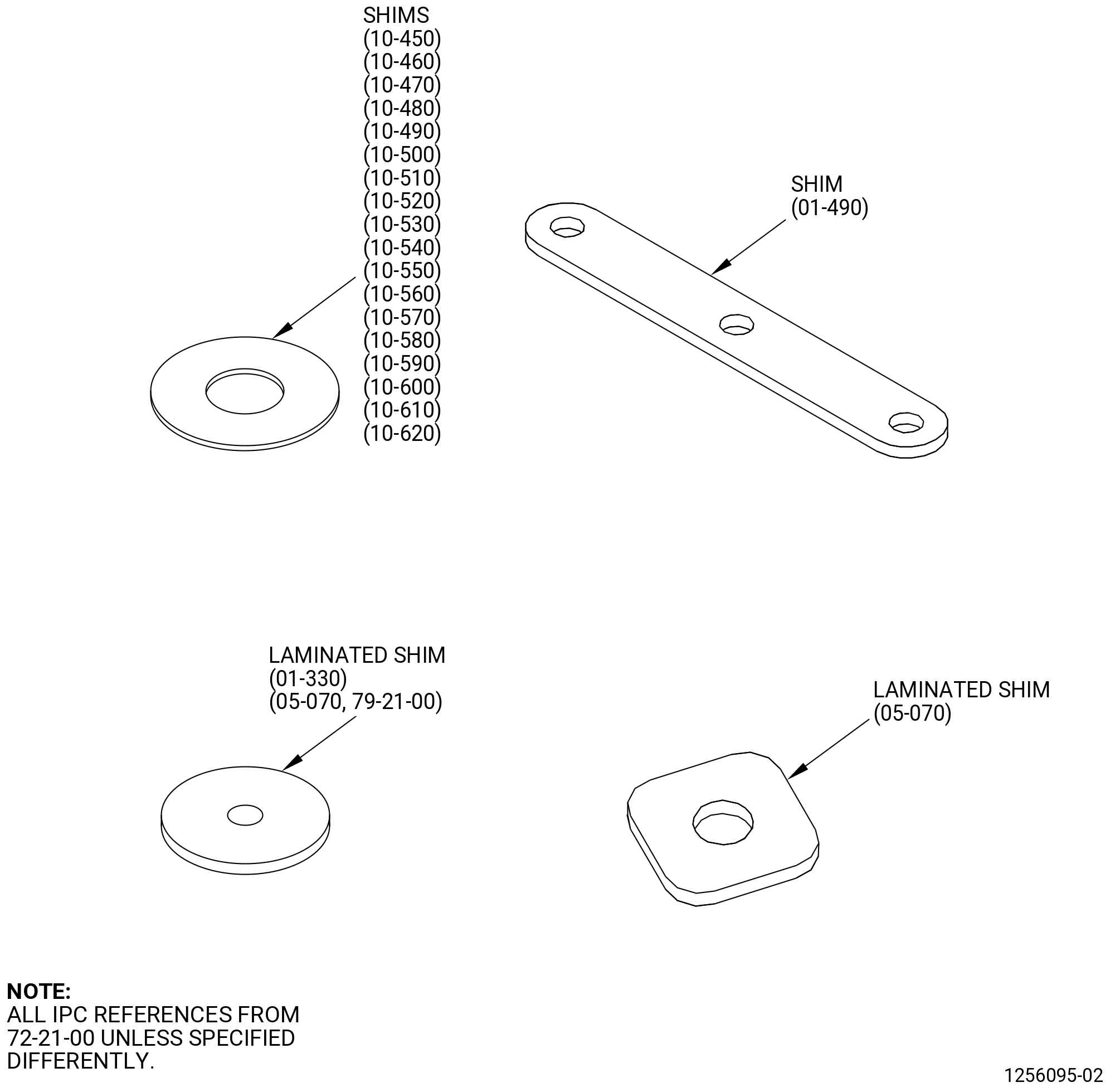
| A. | Do an inspection of the laminated shims and shims as follows. Refer to Figure 801. |
| (1) | Cracks: |
| Maximum serviceable limit: |
|
| Repair method: |
|
| Subtask 72-21-99-220-002 |
| (2) | Nicks, dents, and scratches: |
| Maximum serviceable limit: |
|
| Repair method: |
|
| Subtask 72-21-99-220-003 |
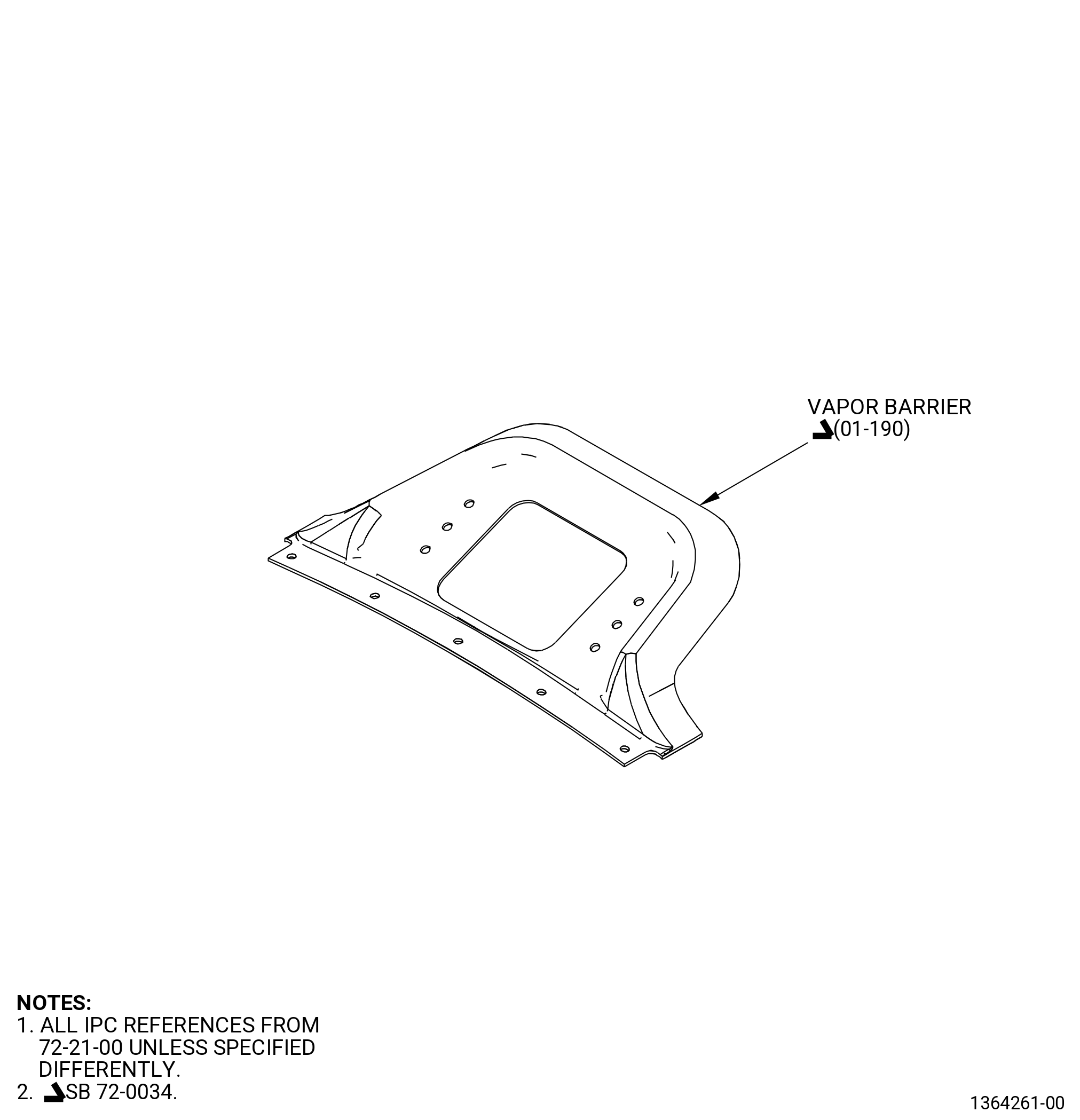
| B. | Do an inspection of the vapor barrier as follows. Refer to Figure 802 and Figure 802A. |
| (1) | Cracks: |
| Maximum serviceable limit: |
|
| Repair method: |
|
| Subtask 72-21-99-220-004 |
| (2) | Burnishing or wear: |
| Maximum serviceable limit: |
|
| Repair method: |
|
| Subtask 72-21-99-220-059 |
| (3) | Nicks, dents, scratches, and gouges: |
| Maximum serviceable limit: |
|
| Repair method: |
|
| Subtask 72-21-99-220-005 |
| (4) | Deformation around mounting holes: |
| Maximum serviceable limit: |
|
| Repair method: |
|
|
|
| Subtask 72-21-99-220-009 |
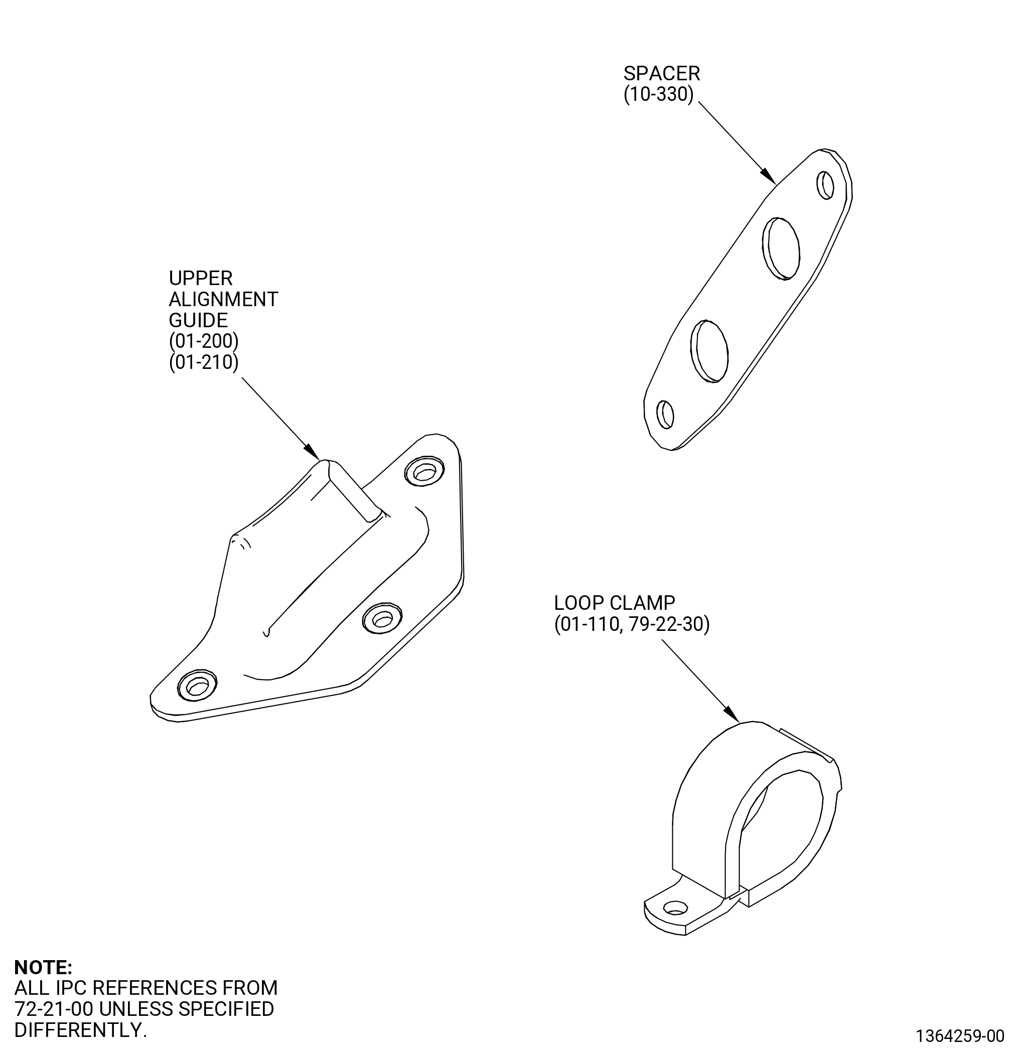
| C. | Do an inspection of the loop clamp. Refer to Figure 803. |
| (1) | Cracks: |
| Maximum serviceable limit: |
|
| Repair method: |
|
| Subtask 72-21-99-220-010 |
| (2) | Damaged cushion material: |
| Maximum serviceable limit: |
|
| Repair method: |
|
| Subtask 72-21-99-220-011 |
| D. | Do an inspection of the upper alignment guides. Refer to Figure 803. |
| (1) | Cracks: |
| Maximum serviceable limit: |
|
| Repair method: |
|
| Subtask 72-21-99-220-012 |
| (2) | Nicks, dents, and scratches: |
| Maximum serviceable limit: |
|
| Repair method: |
|
| Subtask 72-21-99-220-013 |
| E. | Do an inspection of the spacer. Refer to Figure 803. |
| (1) | Cracks: |
| Maximum serviceable limit: |
|
| Repair method: |
|
| Subtask 72-21-99-220-014 |
| (2) | Nicks, dents, and scratches: |
| Maximum serviceable limit: |
|
| Repair method: |
|
| Subtask 72-21-99-220-015 |
| (3) | Missing coating: |
| Maximum serviceable limit: |
|
| Repair method: |
|
| Subtask 72-21-99-220-016 |
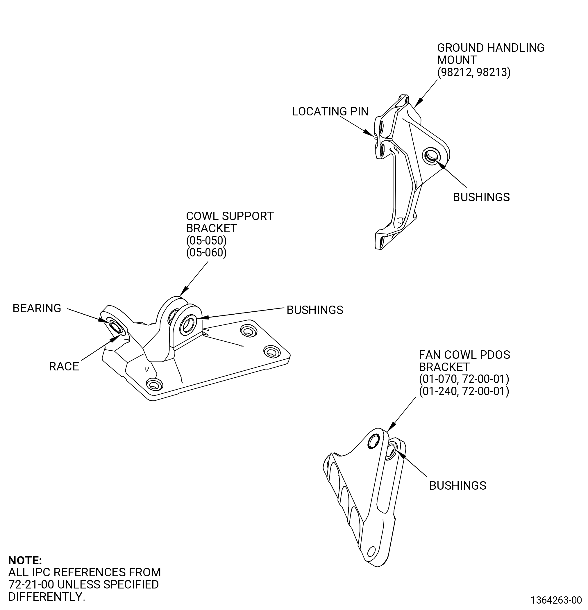
| F. | Do an inspection of the cowl support brackets, ground handling mounts, fan cowl PDOS brackets, and fan bootstrap brackets as follows. Refer to Figure 804. |
| (1) | Cracks: |
| Maximum serviceable limit: |
|
| Repair method: |
|
| Subtask 72-21-99-220-017 |
| (2) | Nicks, dents, and scratches: |
| Maximum serviceable limit: |
|
| Maximum repairable limit: |
|
| Repair method: |
|
| Subtask 72-21-99-220-018 |
| (3) | Loose or missing bushing on the cowl support brackets, ground handling mounts, or fan cowl PDOS brackets: |
| Maximum serviceable limit: |
|
| Repair method: |
|
| Subtask 72-21-99-220-019 |
| (4) | Worn bushing on the cowl support brackets or ground handling mounts: |
| Maximum serviceable limit: |
|
| Maximum repairable limit: |
|
| Repair method: |
|
| Subtask 72-21-99-220-020 |
| (5) | Fretting or galling of bearing on cowl support brackets: |
| Maximum serviceable limit: |
|
| Repair method: |
|
| Subtask 72-21-99-220-052 |
| (6) | Looseness of bearing on cowl support brackets: |
| Maximum serviceable limit: |
|
| Repair method: |
|
| Subtask 72-21-99-220-051 |
| (7) | Corrosion on cowl support brackets: |
| Maximum serviceable limit: |
|
| Repair method: |
|
| Subtask 72-21-99-220-021 |
| (8) | Missing or loose locating pin on the ground handling mounts: |
| Maximum serviceable limit: |
|
| Repair method: |
|
| Subtask 72-21-99-220-053 |
| (9) | Worn bushing on the fan cowl PDOS brackets: |
| Maximum serviceable limit: |
|
| Repair method: |
|
| Subtask 72-21-99-220-022 |
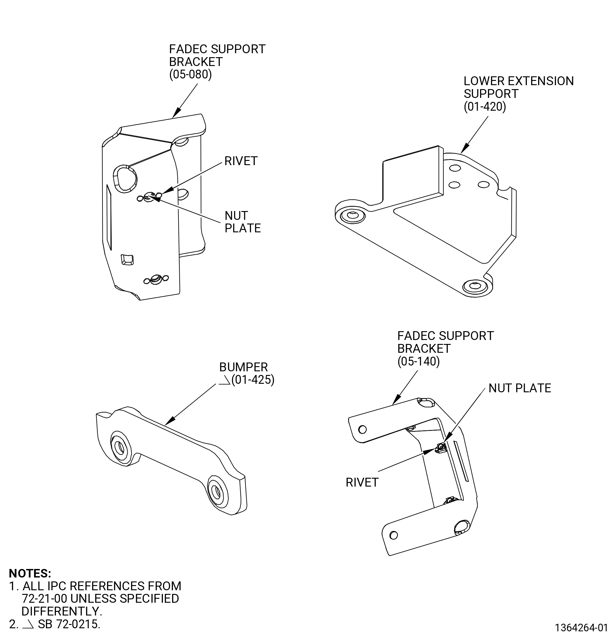
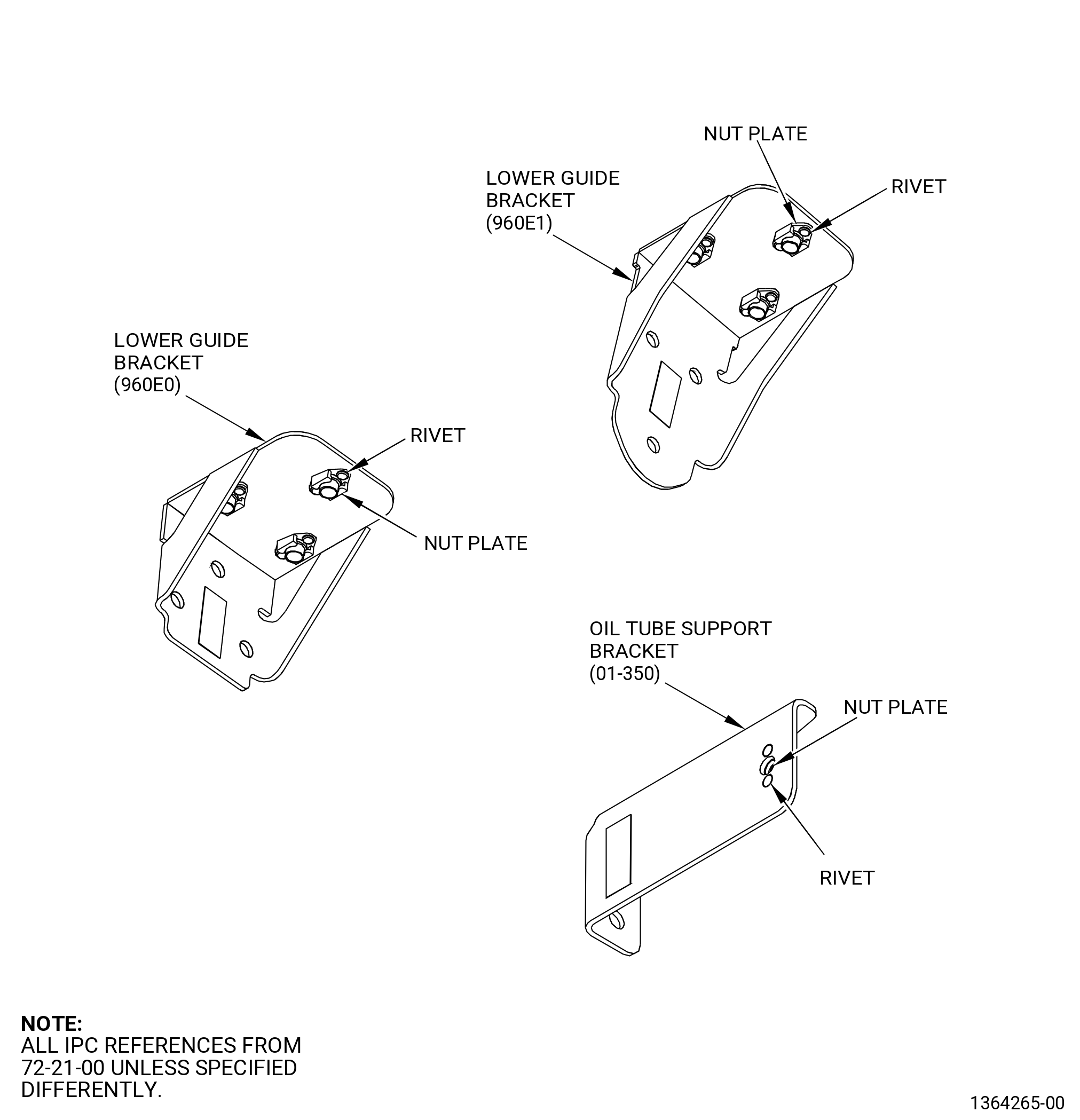
| G. | Do an inspection of the lower extension support, oil tube support bracket, lower guide brackets, and FADEC support brackets as follows. Refer to Figure 805. |
| (1) | Cracks: |
| Maximum serviceable limit: |
|
| Repair method: |
|
| Subtask 72-21-99-220-023 |
| (2) | Nicks, dents, and scratches: |
| Maximum serviceable limit: |
|
| Maximum repairable limit: |
|
| Repair method: |
|
| Subtask 72-21-99-220-024 |
| (3) | Missing or loose nut plates of the oil tube support bracket, lower guide brackets, and FADEC support brackets: |
| Maximum serviceable limit: |
|
| Repair method: |
|
| Subtask 72-21-99-220-025 |
| (4) | Damaged threads on nut plates of the oil tube support bracket, lower guide brackets, and FADEC support brackets: |
| Maximum serviceable limit: |
|
| Repair method: |
|
| Subtask 72-21-99-220-026 |
| (5) | Damaged to self-locking feature on nut plates of the oil tube support bracket, lower guide brackets, and FADEC support brackets: |
| Maximum serviceable limit: |
|
| Repair method: |
|
| Subtask 72-21-99-220-027 |
| (6) | Missing or loose rivets on the nut plate of the oil tube support bracket, lower guide brackets, and FADEC support brackets: |
| Maximum serviceable limit: |
|
| Maximum repairable limit: |
|
| Repair method: |
|
| Subtask 72-21-99-220-064 |
| * * * SB 72-0215( Introduction of Metal Bumper ) |
| H. | Do an inspection of the bumper (01-425 , 72-21-00) (SIN 84518). Refer to Figure 805. |
| (1) | Cracks: |
| Maximum serviceable limit: |
|
| Repair method: |
|
| Subtask 72-21-99-220-065 |
| (2) | Nicks, dents, and scratches: |
| Maximum serviceable limit: |
|
| Maximum repairable limit: |
|
| Repair method: |
|
| * * * END SB 72-0215 |
| Subtask 72-21-99-220-028 |
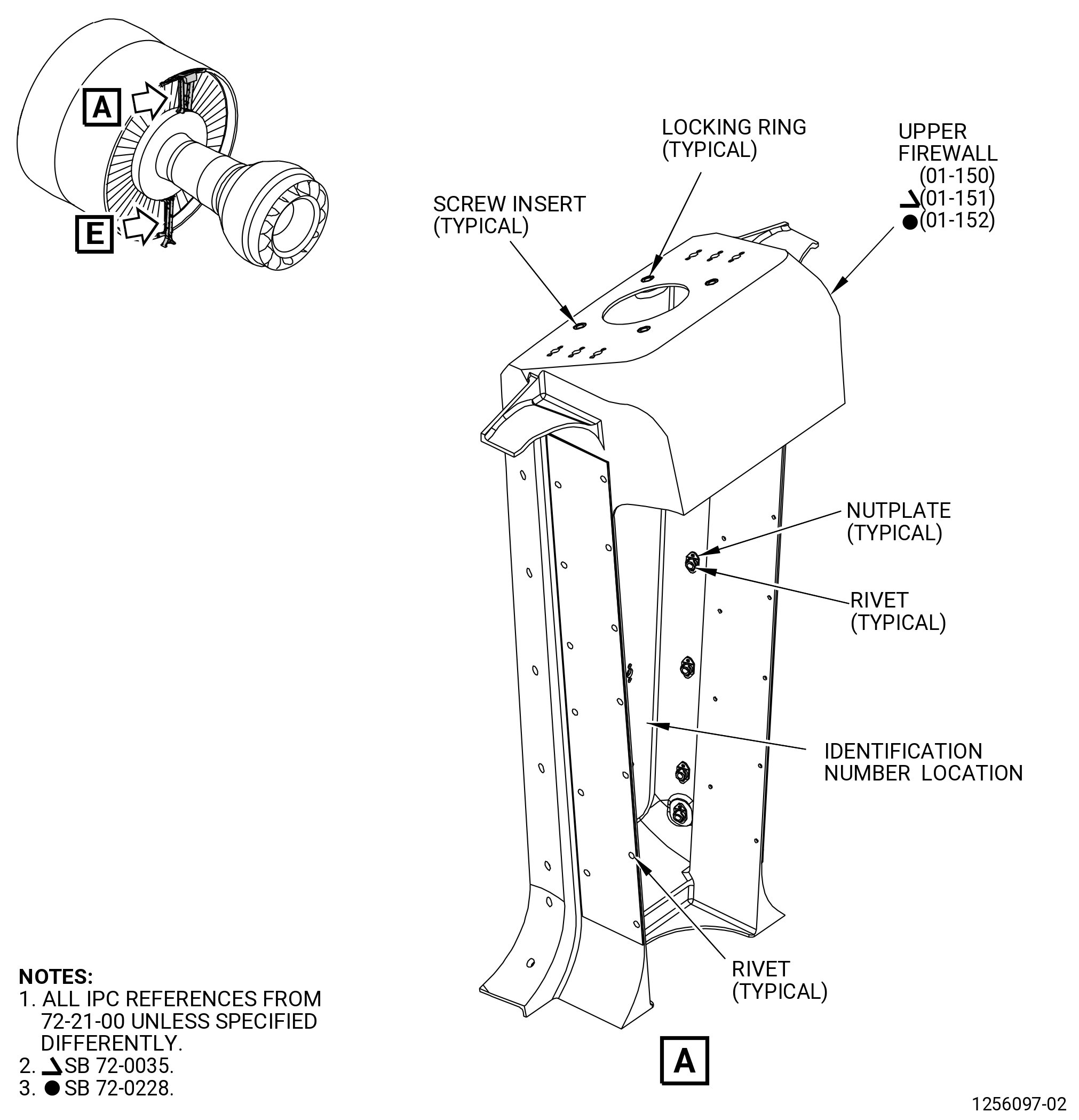
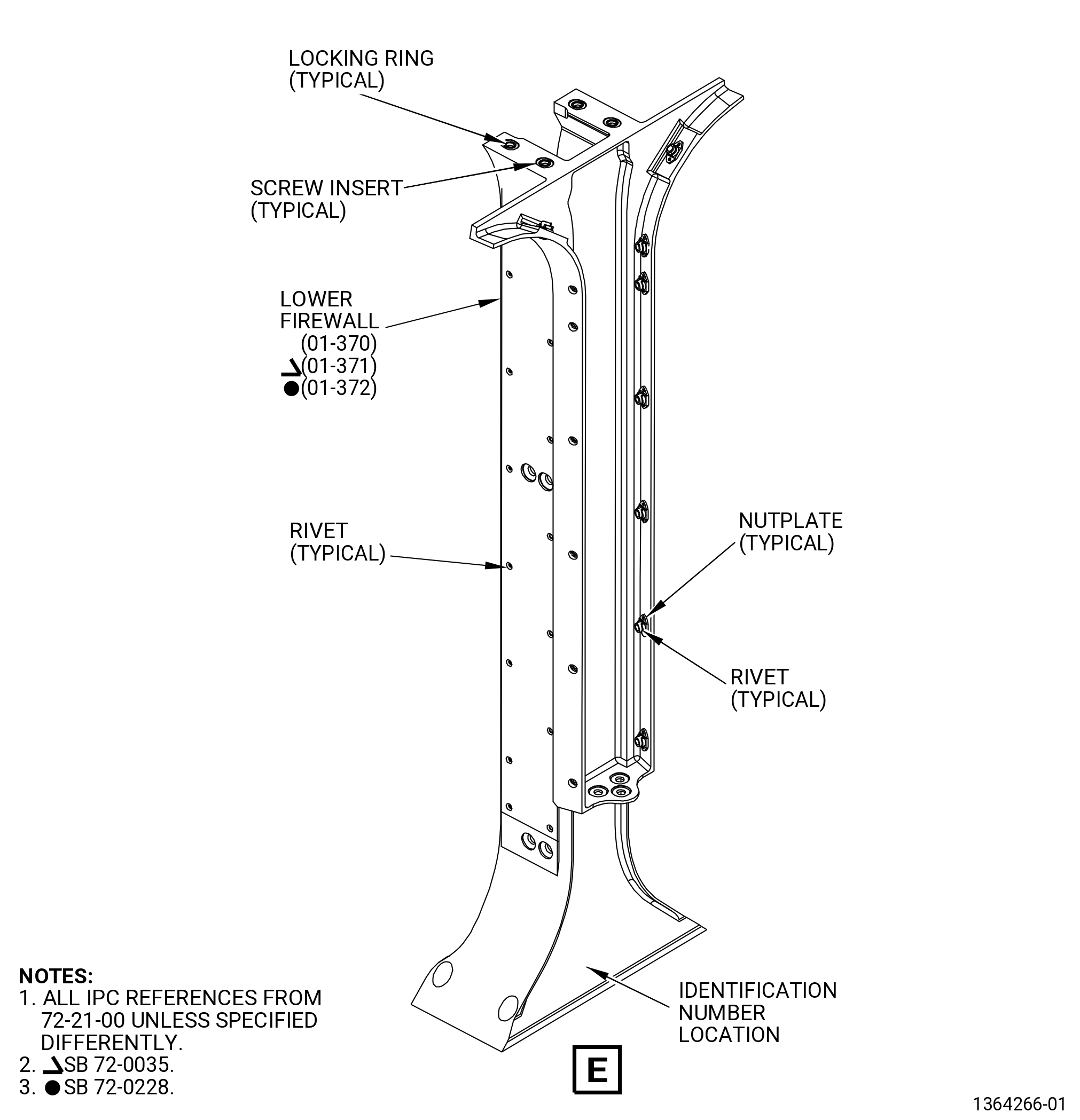
| I. | Do an inspection of the upper firewall and lower firewall as follows. Refer to Figure 806. |
| (1) | Cracks: |
| Maximum serviceable limit: |
|
| Repair method: |
|
| Subtask 72-21-99-220-029 |
| (2) | Nicks, dents, and scratches: |
| Maximum serviceable limit: |
|
| Maximum repairable limit: |
|
| Repair method: |
|
| Subtask 72-21-99-220-060 |
| (3) | Burnishing or wear on lower firewall: |
| Maximum serviceable limit: |
|
| Repair method: |
|
| Subtask 72-21-99-220-030 |
| (4) | Missing or loose screw inserts: |
| Maximum serviceable limit: |
|
| Maximum repairable limit: |
|
| Repair method: |
|
| Subtask 72-21-99-220-031 |
| (5) | Damaged threads on screw inserts: |
| Maximum serviceable limit: |
|
| Repair method: |
|
| Subtask 72-21-99-220-032 |
| (6) | Missing or loose locking rings: |
| Maximum serviceable limit: |
|
| Repair method: |
|
| Subtask 72-21-99-220-033 |
| (7) | Damaged threads on nut plates |
| Maximum serviceable limit: |
|
| Repair method: |
|
| Subtask 72-21-99-220-034 |
| (8) | Missing or loose rivet on nut plates: |
| Maximum serviceable limit: |
|
| Maximum repairable limit: |
|
| Repair method: |
|
| Subtask 72-21-99-220-035 |
| J. | Do an inspection of the lower seal as follows. Refer to Figure 807. |
| (1) | Cracks: |
| Maximum serviceable limit: |
|
| Repair method: |
|
| Subtask 72-21-99-220-036 |
| (2) | Missing or damaged material: |
| Maximum serviceable limit: |
|
| Repair method: |
|
| Subtask 72-21-99-220-037 |
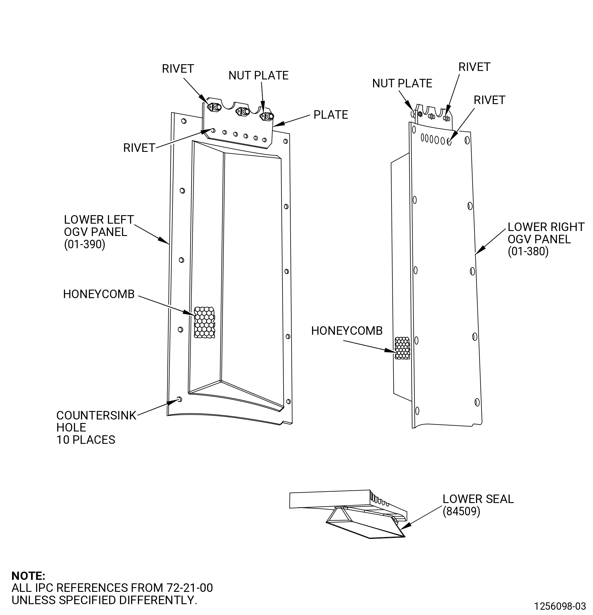
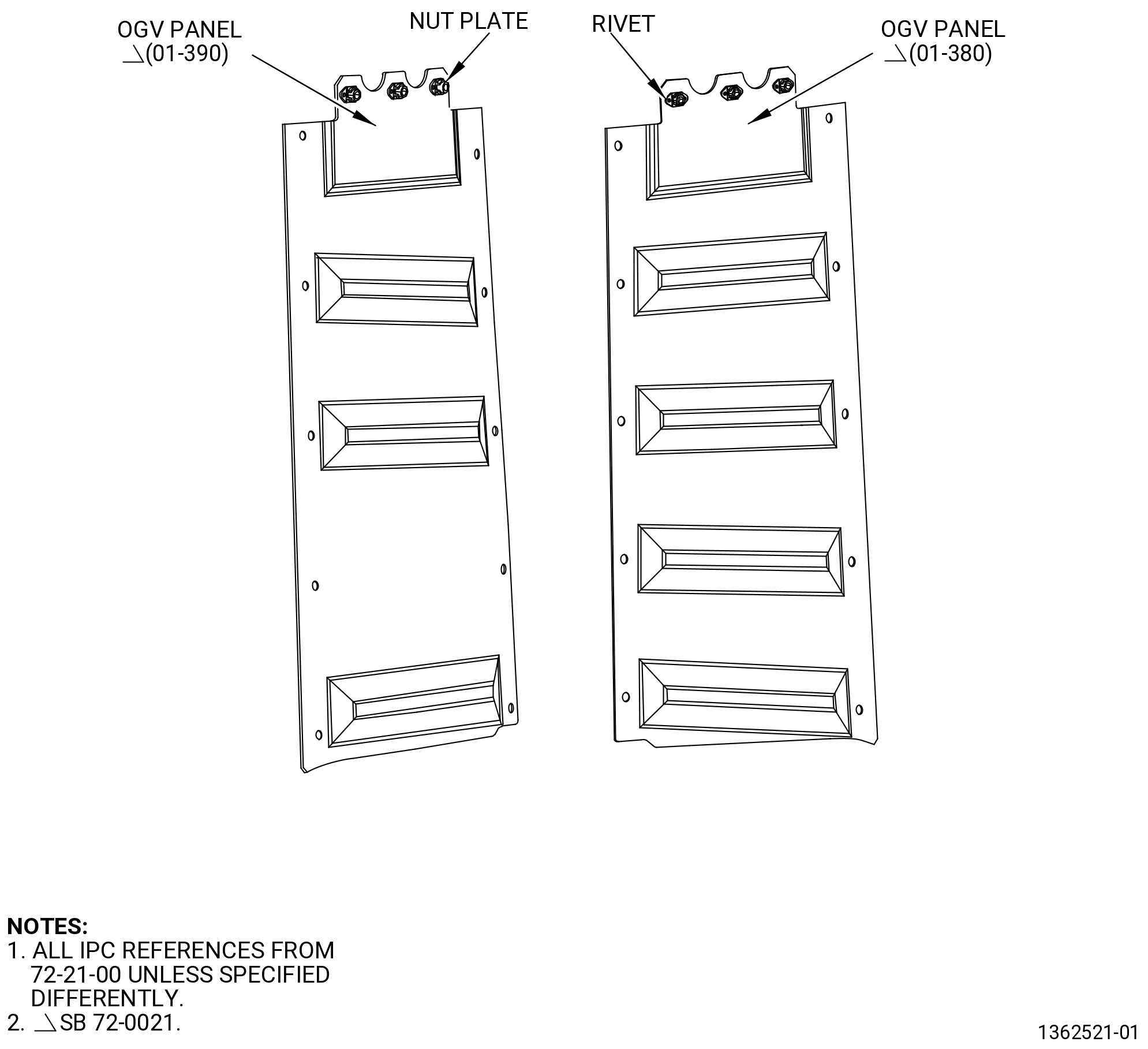
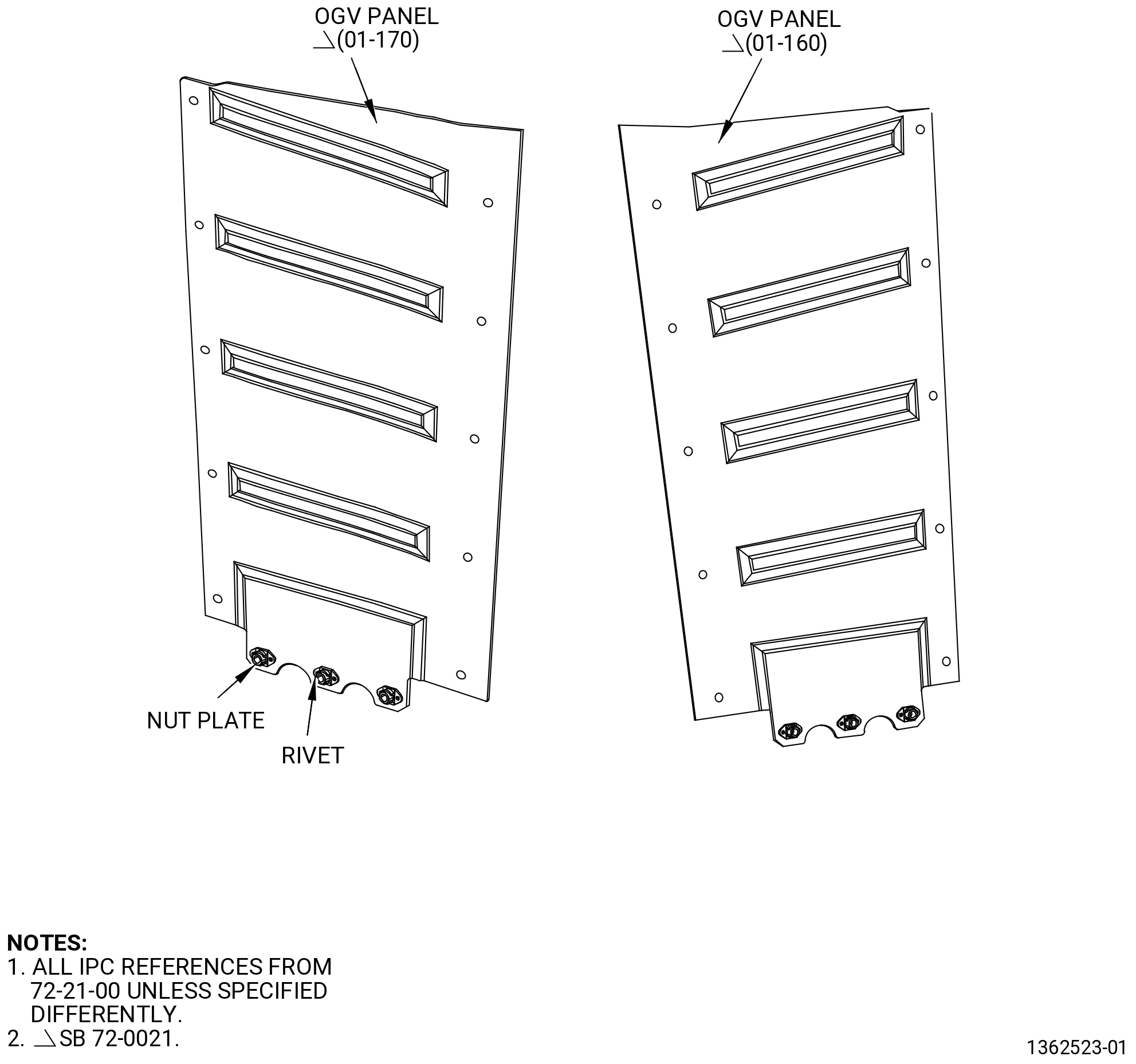
| K. | Do an inspection of each OGV panel and each fillet fairing as follows. Refer to Figure 807, Figure 807A, Figure 808, Figure 808A, and Figure 809. |
| (1) | Cracks: |
| Maximum serviceable limit: |
|
| Repair method: |
|
| Subtask 72-21-99-220-038 |
| (2) | Nicks and scratches: |
| Maximum serviceable limit: |
|
| Repair method: |
|
| Subtask 72-21-99-220-039 |
| (3) | Dents, holes, or punctures: |
| Maximum serviceable limit: |
|
| Repair method: |
|
| Subtask 72-21-99-220-040 |
| (4) | Delamination on the corners of the OGV panels or fairing fillets: |
| Maximum serviceable limit: |
|
| Repair method: |
|
| Subtask 72-21-99-220-041 |
| (5) | Delamination on all other areas of each OGV panels or fairing fillets: |
| Maximum serviceable limit: |
|
| Repair method: |
|
| Subtask 72-21-99-220-042 |
| (6) | Missing plates, rivets and nut plates on the OGV panels: |
| Maximum serviceable limit: |
|
| Repair method: |
|
| Subtask 72-21-99-220-043 |
| (7) | Damaged threads on nut plates on the OGV panels: |
| Maximum serviceable limit: |
|
| Repair method: |
|
| Subtask 72-21-99-220-044 |
| (8) | Self-locking feature on nut plates on the OGV panels: |
| Maximum serviceable limit: |
|
| Repair method: |
|
| Subtask 72-21-99-220-054 |
| * * * PRE SB 72-0021( OGV Panels Made of Phenolic Resin ) |
| (9) | Cratering or hole breakout on the OGV panels: |
| Maximum serviceable limit: |
|
| Repair method: |
|
| NOTE: |
|
| Subtask 72-21-99-220-055 |
| (10) | Blocked or partially filled holes in facesheet over bond joints on the OGV panels: |
| Maximum serviceable limit: |
|
| Repair method: |
|
| NOTE: |
|
| Subtask 72-21-99-220-056 |
| (11) | Blocked or partially filled holes in the acoustic area on the OGV panels: |
| Maximum serviceable limit: |
|
| Repair method: |
|
| NOTE: |
|
| * * * END PRE SB 72-0021 |
| Subtask 72-21-99-220-061 |
| * * * SB 72-0021( OGV Panels Made of Carbon Fabric ) |
| (12) | Surface porosity on the OGV panel: |
| Maximum serviceable limit: |
|
| Repair method: |
|
| NOTE: |
|
| NOTE: |
|
| Subtask 72-21-99-220-062 |
| (13) | Use a steel rod, 0.375 inch (9.53 mm) in diameter and 2.00 inches (50.8 mm) in length, with a round end to tap on the stiffening cap in the damaged area while listening for clicking sounds. |
| • |
|
| • |
|
| Subtask 72-21-99-220-063 |
| (14) | Delamination in the OGV panel: |
| Maximum serviceable limit: |
|
| Repair method: |
|
| NOTE: |
|
| * * * END SB 72-0021( ) |
|
|
|
|
| Subtask 72-21-99-220-045 |
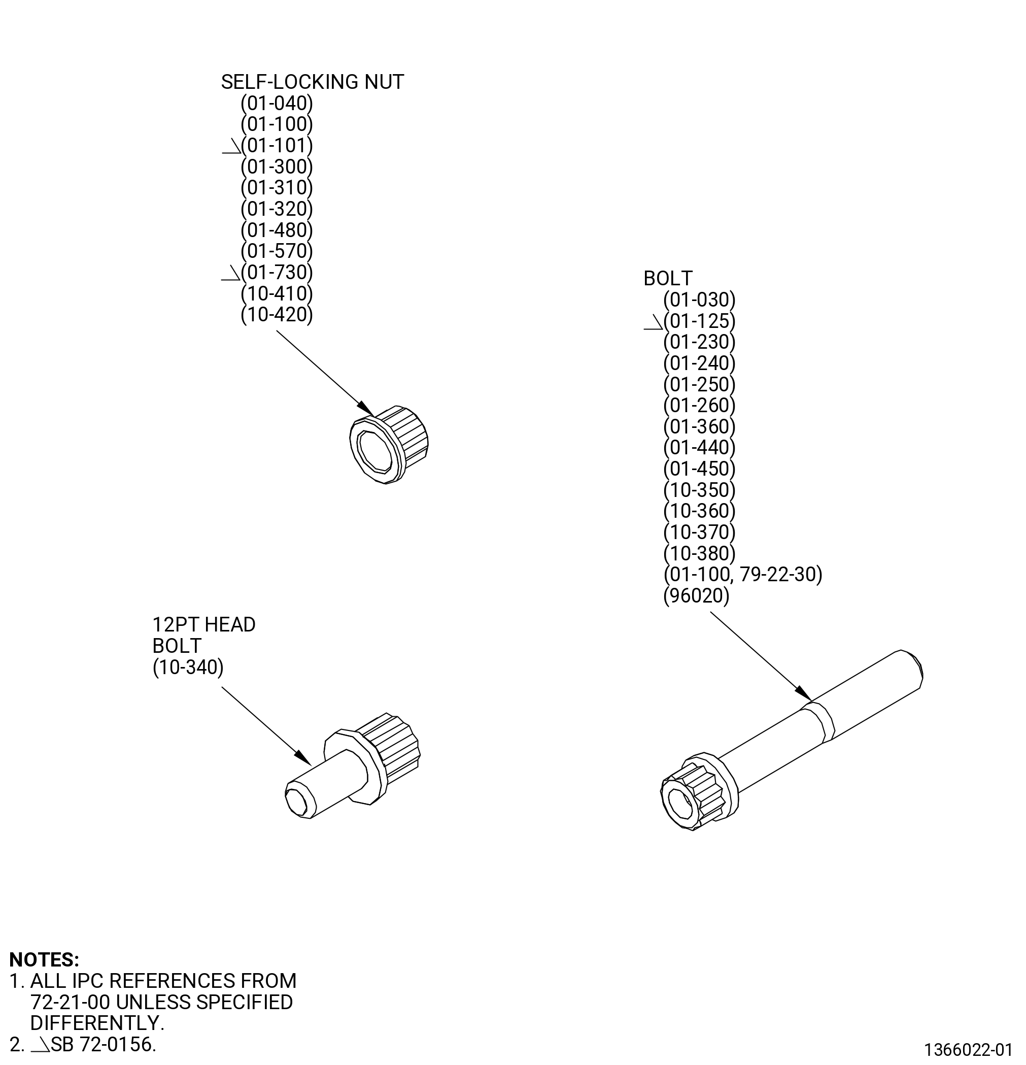
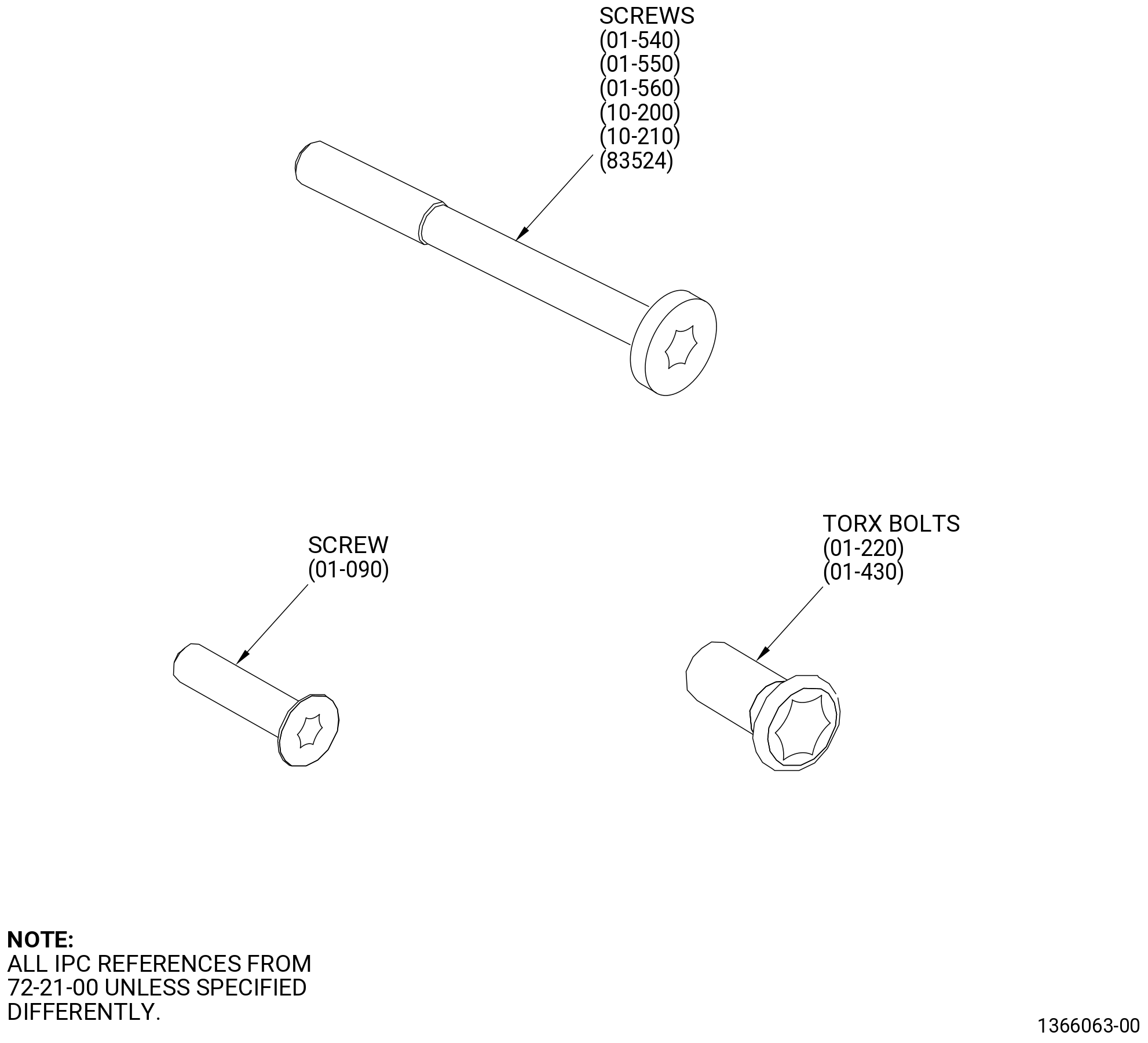
| L. | Do an inspection of each bolt and each screw for. Refer to Figure 810. |
| (1) | Cracks: |
| Maximum serviceable limit: |
|
| Repair method: |
|
| Subtask 72-21-99-220-046 |
| (2) | Damaged head on bolts or screws: |
| Maximum serviceable limit: |
|
| Repair method: |
|
| Subtask 72-21-99-220-047 |
| M. | Do an inspection of each self-locking nut for: |
| (1) | Thread damage: |
| Maximum serviceable limit: |
|
| Repair method: |
|
| Subtask 72-21-99-220-048 |
| (2) | Loss of self-locking quality: |
| Maximum serviceable limit: |
|
| Repair method: |
|
| Subtask 72-21-99-220-050 |
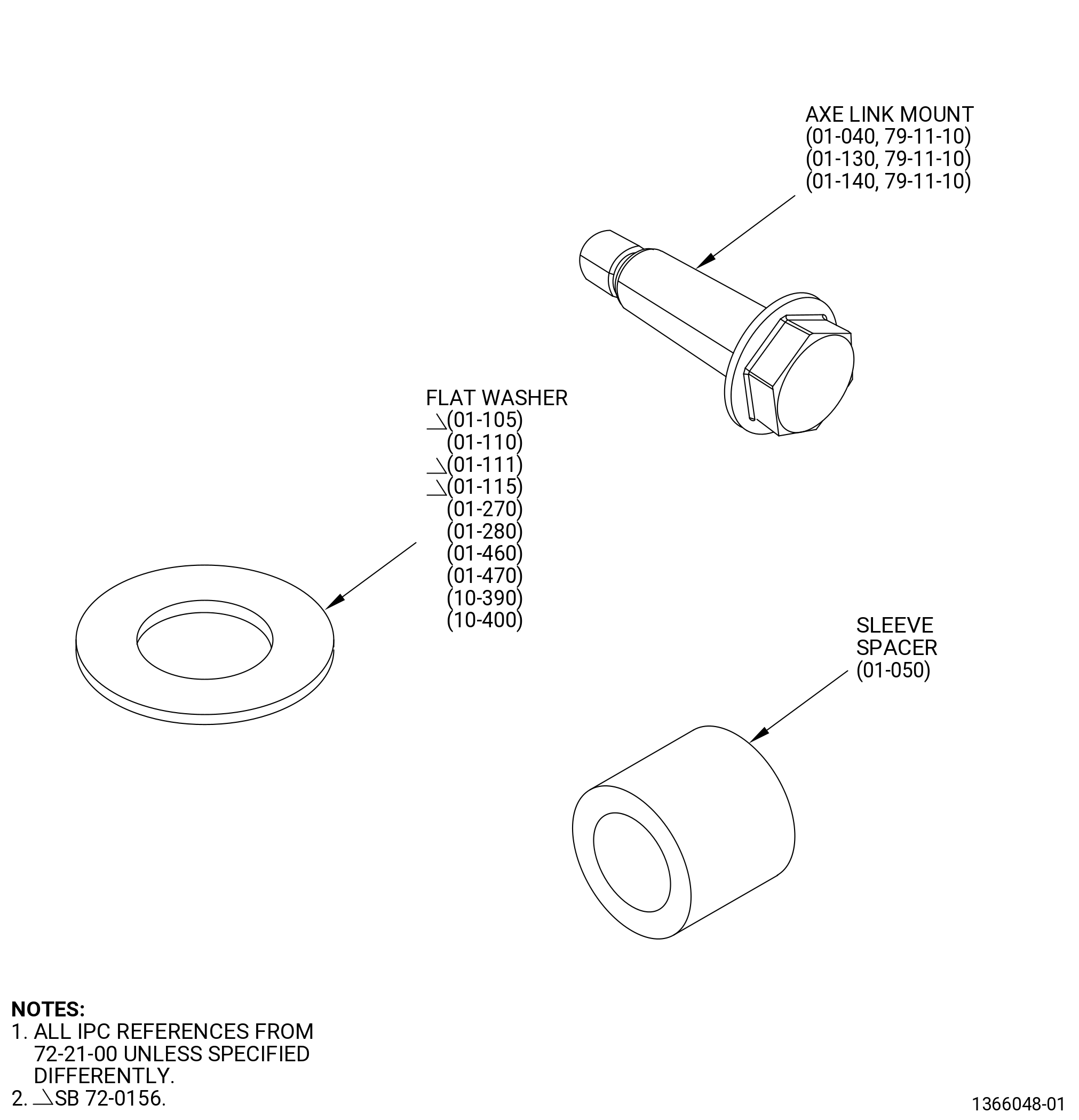
| N. | Do an inspection of each washer and sleeve spacer for. Refer to Figure 811. |
| (1) | Cracks: |
| Maximum serviceable limit: |
|
| Repair method: |
|
| Subtask 72-21-99-220-057 |
| O. | Do an inspection of each axe link mount. Refer to Figure 811. |
| (1) | Cracks: |
| Maximum serviceable limit: |
|
| Repair method: |
|
| Subtask 72-21-99-220-058 |
| (2) | Damaged head: |
| Maximum serviceable limit: |
|
| Repair method: |
|
| Subtask 72-21-99-220-073 |
| * * * PRE SB 72-0021 |
| P. | Do an inspection of the OGV panels (01-160 , 72-21-00) (SIN 84402), (01-170 , 72-21-00) (SIN 84403), (01-380 , 72-21-00) (SIN 84502), and (01-390 , 72-21-00) (SIN 84503). Refer to Figure 807 and Figure 808. |
| (1) | Wear around the countersink holes of the OGV panels: |
| Maximum serviceable limit: |
|
| Repair method: |
|
| * * * END PRE SB 72-0021 |
| Subtask 72-21-99-220-074 |
| * * * SB 72-0021 |
| Q. | Do an inspection of the OGV panels (01-160 , 72-21-00) (SIN 84402), (01-170 , 72-21-00) (SIN 84403), (01-380 , 72-21-00) (SIN 84502), and (01-390 , 72-21-00) (SIN 84503). |
| (1) | Wear around the countersink holes of the lower OGV panels (01-380 , 72-21-00) (SIN 84502) and (01-390 , 72-21-00) (SIN 84503). Refer to Figure 807. |
| Maximum serviceable limit: |
|
| Repair method: |
|
| Subtask 72-21-99-220-075 |
| (2) | Wear around the countersink holes of the upper OGV panels (01-160 , 72-21-00) (SIN 84402) and (01-170 , 72-21-00) (SIN 84403). Refer to Figure 808. |
| Maximum serviceable limit: |
|
| Repair method: |
|
| * * * END SB 72-0021 |
| Subtask 72-21-99-220-076 |
| * * * SB 72-0233 |
| R. | Do an inspection of the OGV panels (01-160 , 72-21-00) (SIN 84402), (01-170 , 72-21-00) (SIN 84403), (01-380 , 72-21-00) (SIN 84502), and (01-390 , 72-21-00) (SIN 84503). Refer to Figure 807 and Figure 808. |
| (1) | Wear around the countersink holes of the OGV panels: |
| Maximum serviceable limit: |
|
| Repair method: |
|
| * * * END SB 72-0233 |