| GENX-1B ENGINE MANUAL | Dated: 09/30/2022 | |
| EM 72-00-01 , DISASSEMBLY 001 | ||
| FAN STATOR MODULE ASSEMBLY - DISASSEMBLY 001 | ||
| GENX-1B ENGINE MANUAL | Dated: 09/30/2022 | |
| EM 72-00-01 , DISASSEMBLY 001 | ||
| FAN STATOR MODULE ASSEMBLY - DISASSEMBLY 001 | ||
| * * * FOR ALL |
| TASK 72-00-01-040-805 |
| 1 . | General. |
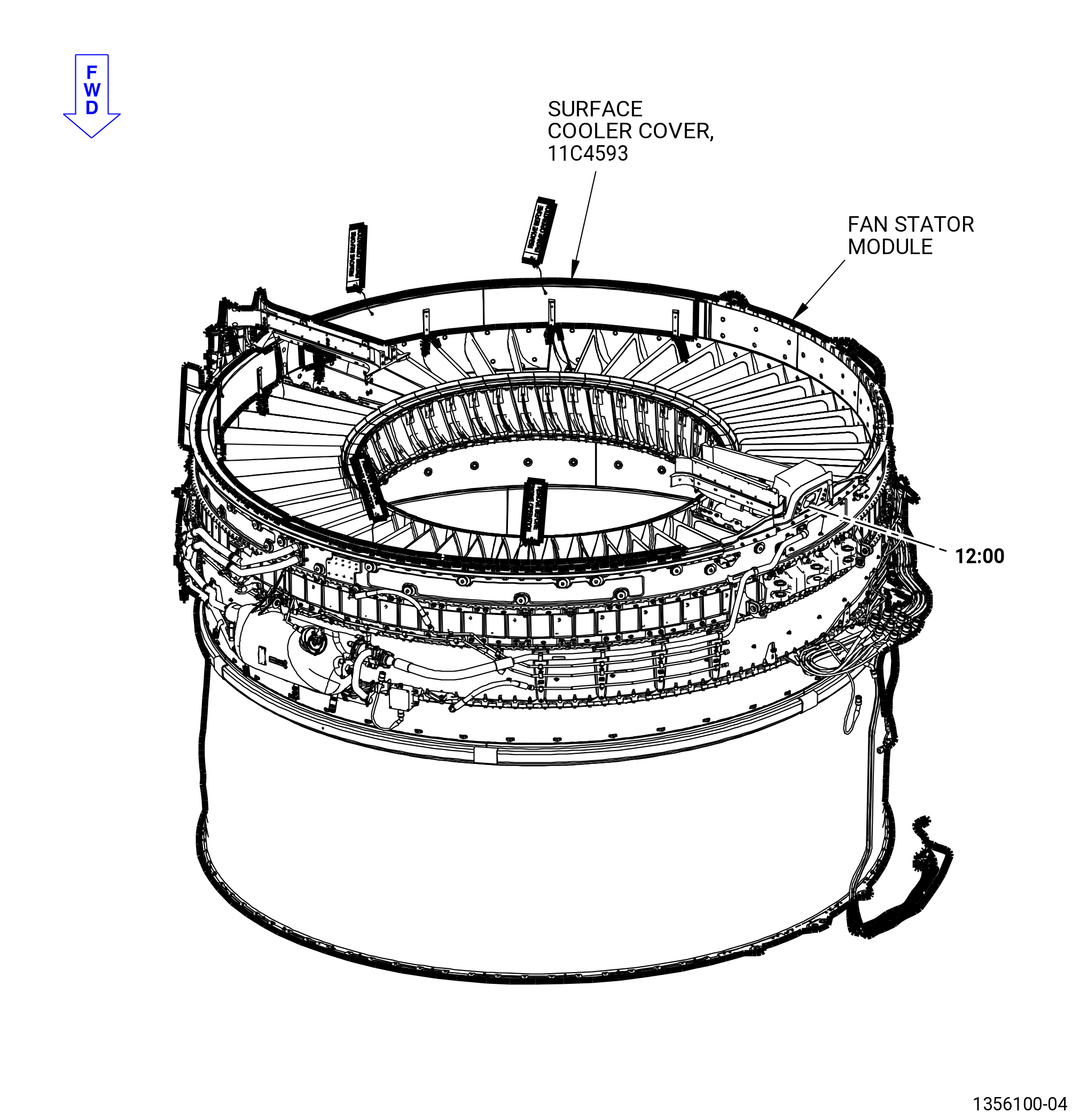
| A. | This procedure gives instructions to disassemble the aft fan stator case assembly (fan stator module). Refer to Figure 501. |
| • |
|
| • |
|
| The fan stator module contains: |
| • |
|
| • |
|
| • |
|
| • |
|
| • |
|
| • |
|
| • |
|
| B. | The fan stator module is installed in the 11C4490 separation dolly. |
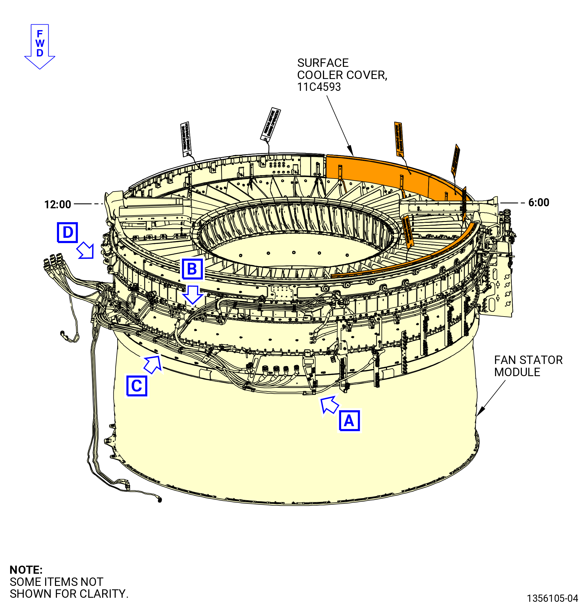
| C. | This procedure begins with the fan stator module assembly installed in the 11C4490 separation dolly with the 11C3199 lift/turn fixture, the 11C4486 fan case ring attached, and the 11C4593 surface cooler covers installed in the fan case, at the equivalent disassembly status of TASK 72-00-01-020-801 (72-00-01, REMOVAL 001). Refer to Figure 502. |
| D. | Do an inspection of all engine parts that you can see when you do maintenance. Examine all parts that are removed and that you will install again. Examine all engine parts that are not removed, but that you can see during maintenance. |
| E. | Before you do this procedure, read the Assembly and Disassembly Techniques section. Refer to TASK 70-10-00-800-009 (ASSEMBLY AND DISASSEMBLY TECHNIQUES) . |
| F. | Read this procedure and become familiar with the instructions before you disassemble the module. |
| 2 . | Tools, Equipment, and Materials. |
| NOTE: |
|
| A. | Tools and Equipment. |
| (1) | Special Tools. |
| (2) | Standard Tools and Equipment. None. |
| (3) | Locally Manufactured Tools. None. |
| B. | Consumable Materials. None. |
| C. | Referenced Procedures. |
|
| D. | Expendable Parts. None. |
| 3 . | Procedure. |
| Subtask 72-00-01-040-050 |
| A. | Remove the fan stator module from the 11C4490 separation dolly and put it, forward end down, on a clean work surface. Refer to Figure 502 and do as follows: |
| (1) | Attach a clevis and an overhead hoist to the left/right hanger of the 11C4486 fan case ring at the 11:00 o'clock and 1:00 o'clock positions. |
| (2) | Attach an overhead hoist to the 11C3199 lift/turn fixture. |
| WARNING: |
|
| (3) | Apply a lift pressure to the fan stator module assembly. |
| CAUTION: |
|
| (4) | Disconnect the 11C4490 separation dolly from the fan stator module. Make sure that the wheel casters on the dolly are in the locked position. |
| (5) | Lift the fan stator module off the 11C4490 separation dolly, and move the dolly away from the fan stator module. |
| (6) | Use the two lifts to safely rotate the fan stator module from the horizontal position to the vertical position with the forward end down. |
| (7) | Lower the fan stator module assembly onto a clean work area or six wooden blocks equally spaced with the forward end down. |
| (8) | Remove the overhead hoists from the 11C4486 fan case ring and the 11C3199 lift/turn fixture. |
| Subtask 72-00-01-040-051 |
| B. | Remove the electrical harnesses from the fan stator module as follows: |
| (1) | Loosen and remove the electrical connectors as follows: |
| (a) | Alternative Procedure Available. If you can get access to the electrical connectors with Teflon slip joint pliers, remove the electrical connectors as follows: |
| 1 | Turn the knurled coupling ring by hand. |
| 2 | Move the backshell assembly from side-to-side, while you turn the knurled coupling ring, until the electrical connectors are loose. |
| 3 | Put the Teflon slip joint pliers on the knurled coupling ring of the electrical connectors. |
| 4 | Loosen the knurled coupling ring with the Teflon slip joint pliers. |
| 5 | Remove the electrical connector. |
| (a).A. | Alternative Procedure. If you cannot get access to the electrical connectors with Teflon slip joint pliers, loosen and remove the electrical connectors as follows: |
| 1 | Turn the knurled coupling ring as you manually loosen the connector. |
| 2 | Manually move the backshell assembly from side-to-side as you manually remove the connector. |
| 3 | Turn the knurled coupling ring to remove the electrical connector. |
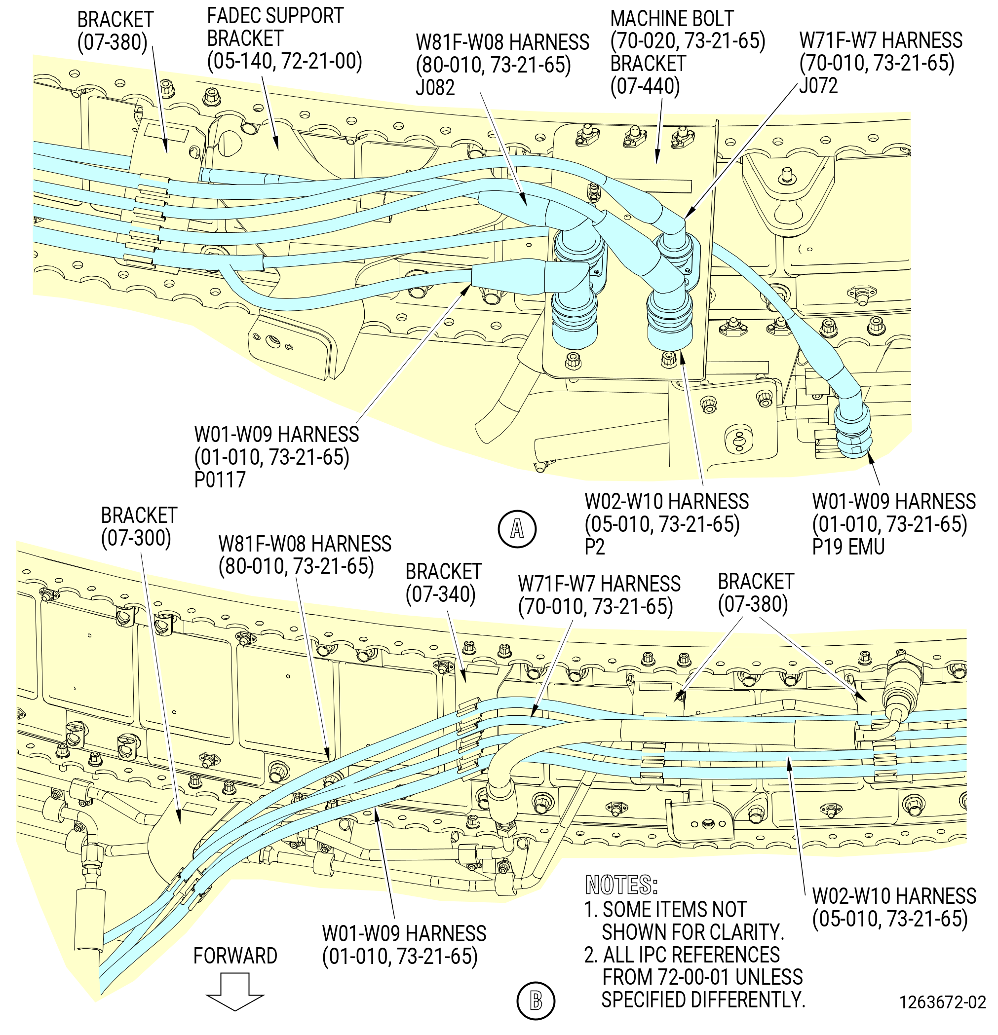
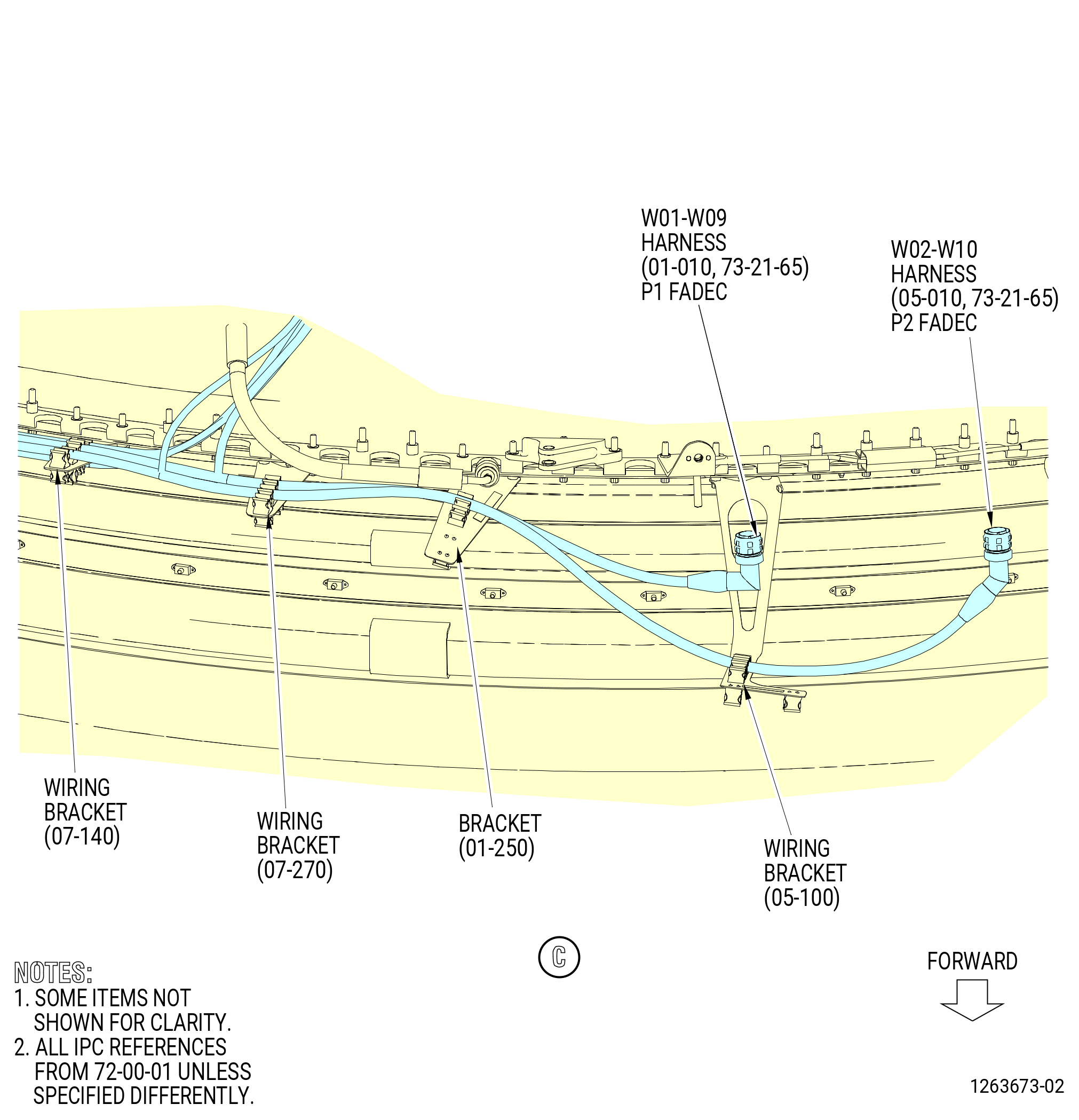
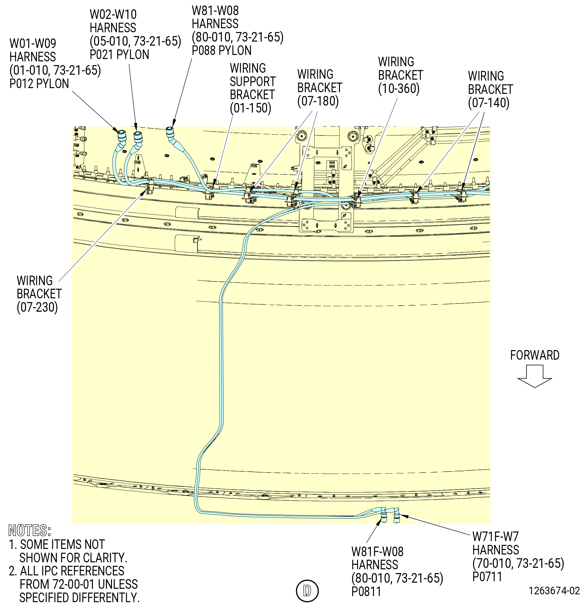
| (2) | Remove the W01 harness (W01-W09 harness) (01-010 , 73-21-65) (SIN 67000), W02 harness (W02-W10 harness) (05-010 , 73-21-65) (SIN 67001), W71F harness (W71F-W7 harness) (70-010 , 73-21-65) (SIN 6700F), and W81F harness (W81F-W08 harness) (80-010 , 73-21-65) (SIN 6700G) from the fan stator module. Refer to Figure 503. |
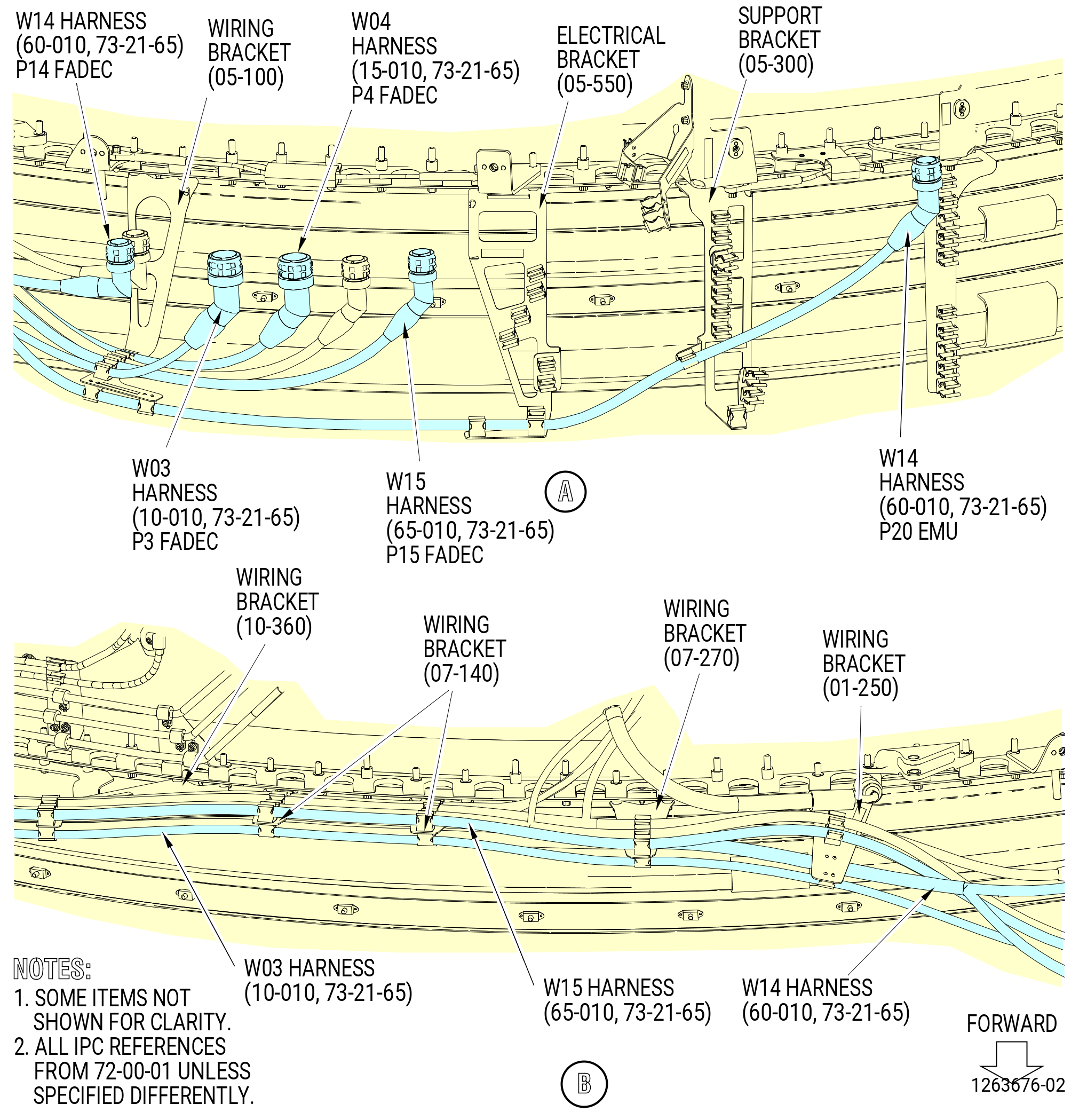
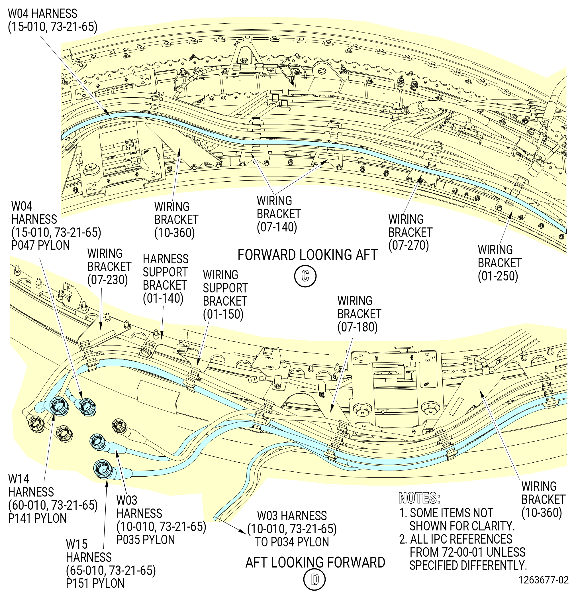
| (3) | Remove the W03 harness (10-010 , 73-21-65) (SIN 67002), W04 harness (15-010 , 73-21-65) (SIN 67003), W14 harness (60-010 , 73-21-65) (SIN 6700C), and W15 harness (65-010 , 73-21-65) (SIN 6700D) from the fan stator module. Refer to Figure 504. |
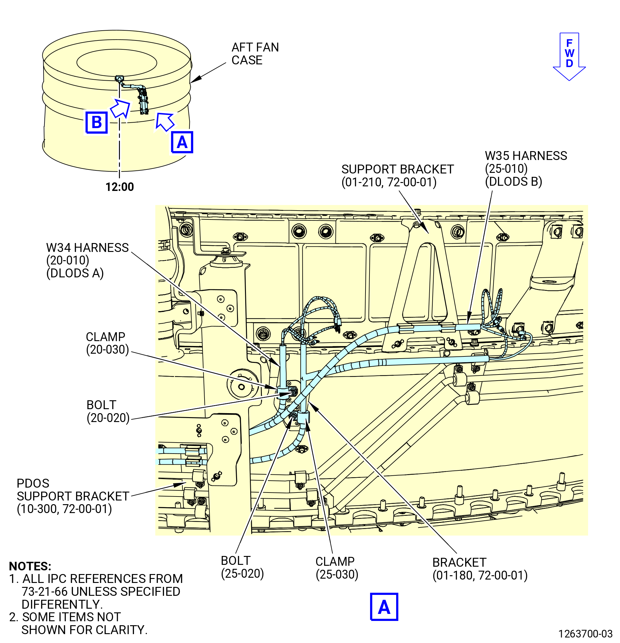
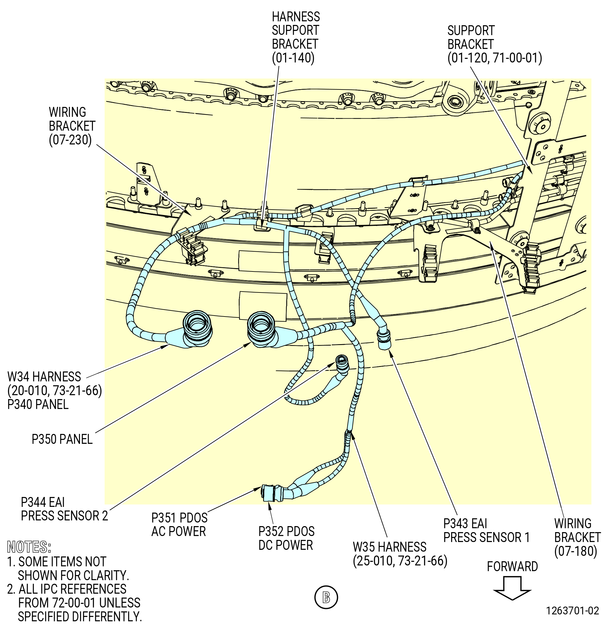
| (4) | Remove the W34 harness (20-010 , 73-21-66) (SIN 68804) and W35 harness (25-010 , 73-21-66) (SIN 68805) from the fan stator module. Refer to Figure 505. |
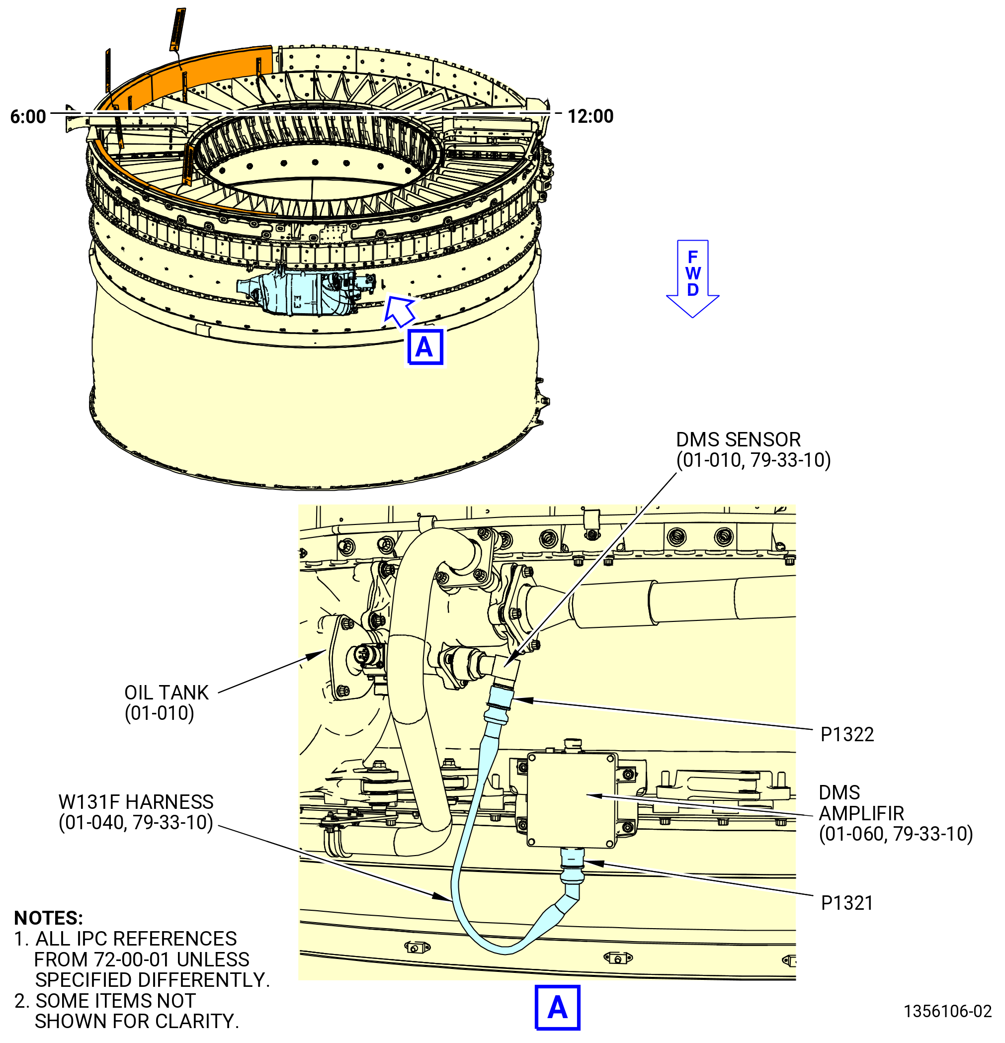
| (5) | Remove the W131F harness (01-040 , 79-33-10) (SIN 6700E) from the fan stator module. Refer to Figure 506. |
| Subtask 72-00-01-040-066 |
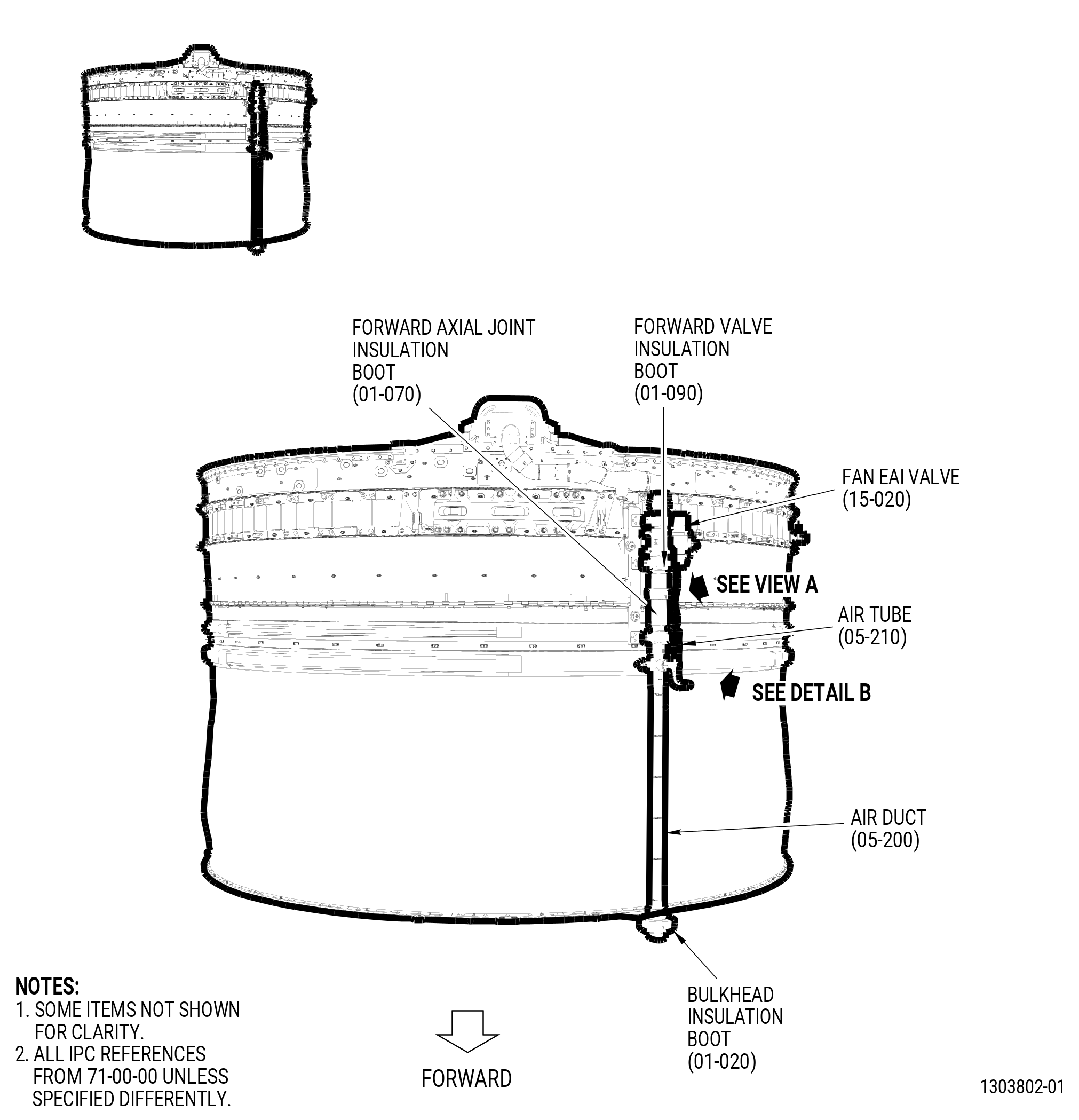
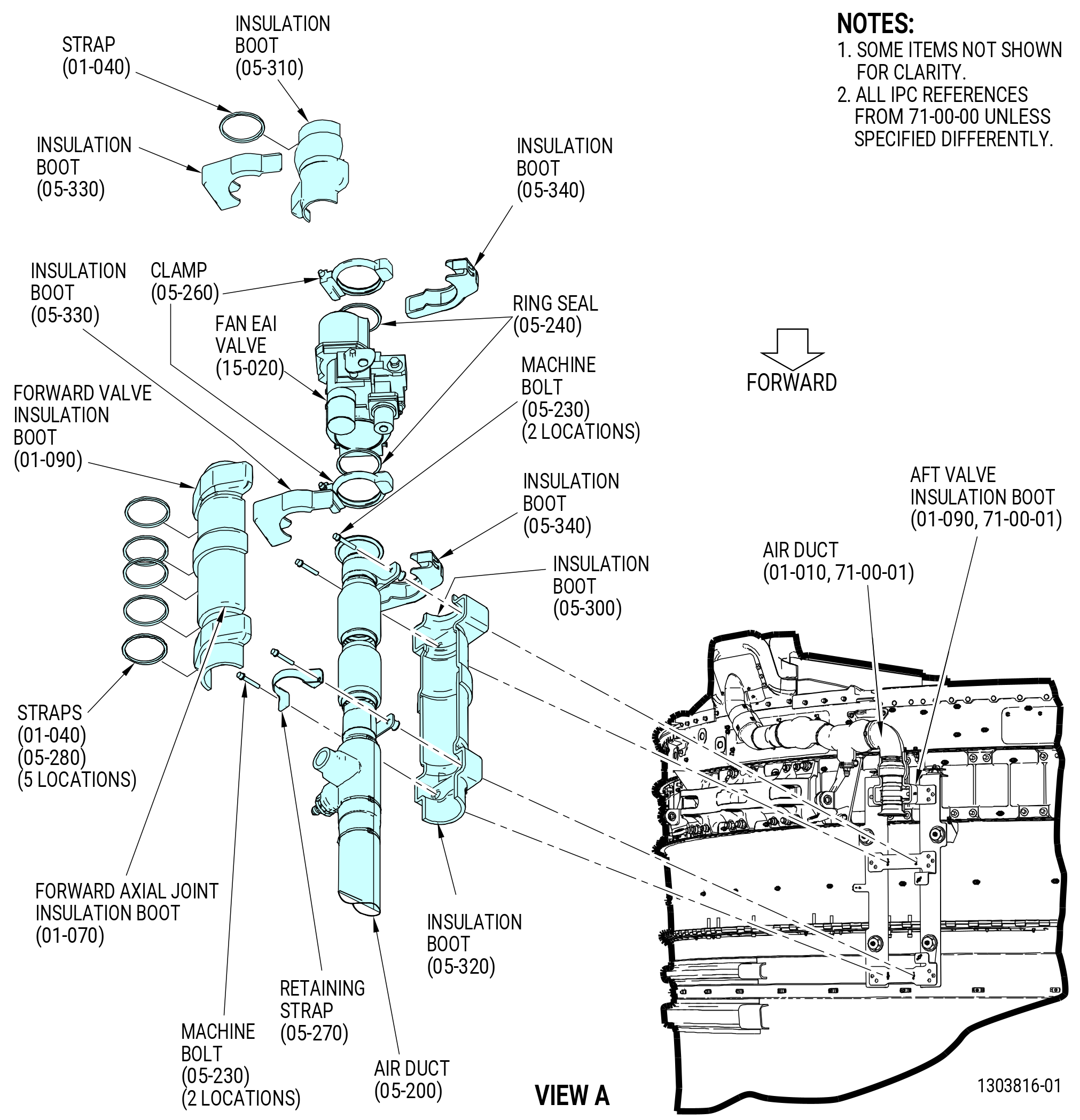
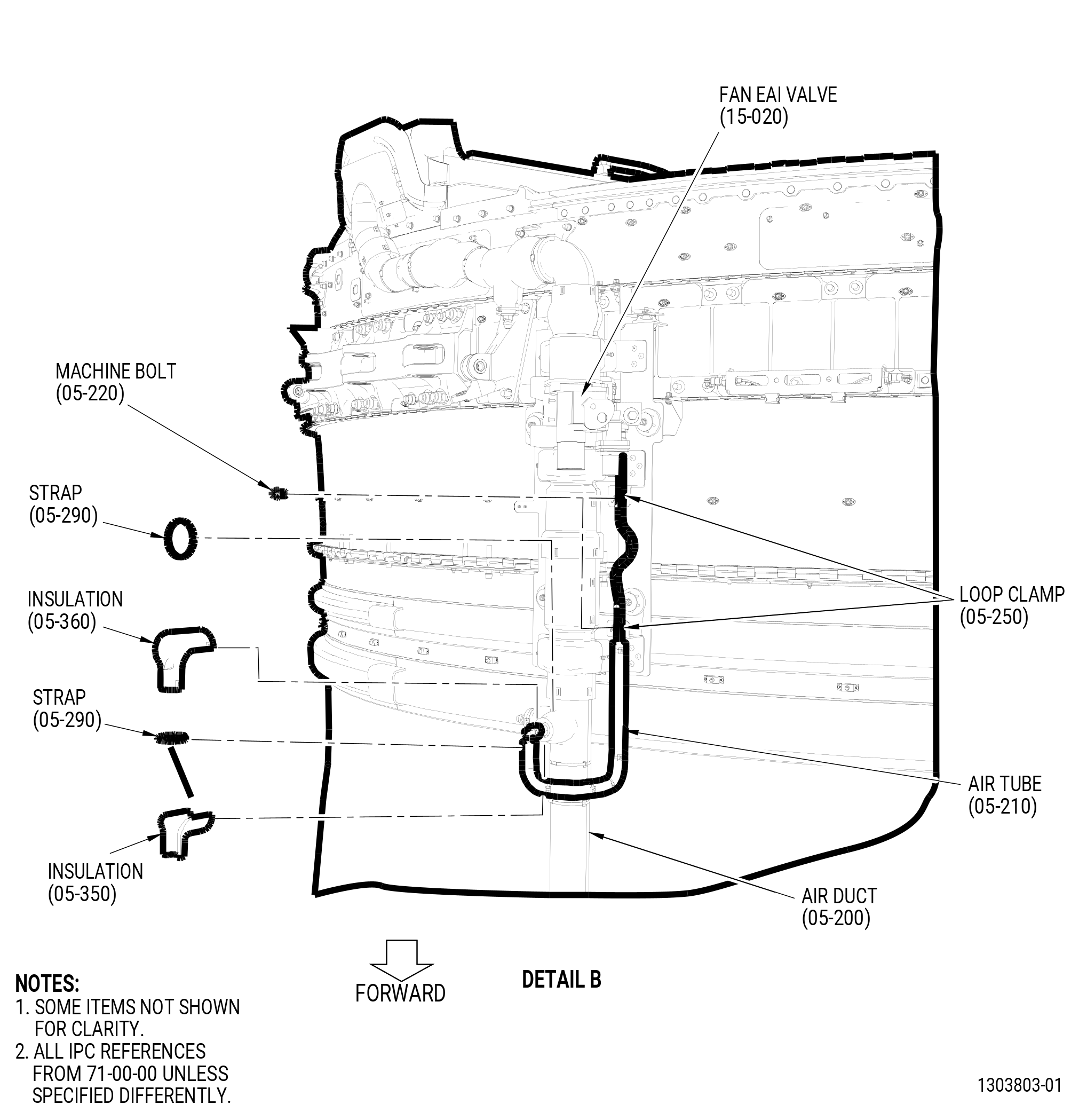
| C. | Remove the fan EAI valve (15-020 , 71-00-00) (SIN C00AK), air duct (05-200 , 71-00-00) (SIN 61003), insulation boots (05-300 , 71-00-00) (SIN 61095) and (05-320 , 71-00-00) (SIN 6109D), and air tube (05-210 , 71-00-00) (SIN 61009) on the aft fan case. Refer to Figure 507 and do as follows: |
| (1) | Remove the forward axial joint insulation boot (01-070 , 71-00-00) (SIN 6109C) and the forward valve insulation boot (01-090 , 71-00-00) (SIN 61094) from the air duct (05-200 , 71-00-00) (SIN 61003) as follows: |
| (a) | Remove and discard the tiedown straps (straps) (01-040 , 71-00-00) (SIN 6108G) and (05-280 , 71-00-00) (SIN 6108G) from the forward axial joint insulation boot and forward valve insulation boot. |
| (b) | Remove the forward axial joint insulation boot and the forward valve insulation boot from the air duct (05-200 , 71-00-00) (SIN 61003). |
| (2) | Remove the insulations (05-360 , 71-00-00) (SIN 6109M) and (05-350 , 71-00-00) (SIN 6109L) and insulation boots (05-340 , 71-00-00) (SIN 6109K), (05-330 , 71-00-00) (SIN 6109F), and (05-310 , 71-00-00) (SIN 6109B) as follows: |
| (a) | Remove and discard the strap (01-040 , 71-00-00) (SIN 6108G) from the insulation boot (05-310 , 71-00-00) (SIN 6109B). |
| (b) | Remove the insulation boots (05-330 , 71-00-00) (SIN 6109F) and (05-340 , 71-00-00) (SIN 6109K) from both sides of the fan EAI valve connections. |
| (c) | Remove the insulation boot (05-310 , 71-00-00) (SIN 6109B) from the aft side of the fan EAI valve on the aft valve insulation boot (01-090 , 71-00-01) (SIN 61093). |
| (d) | Remove and discard the tiedown straps (straps) (05-290 , 71-00-00) (SIN 6108K) from the insulations (05-360 , 71-00-00) (SIN 6109M) and (05-350 , 71-00-00) (SIN 6109L). |
| (e) | Remove the insulations (05-360 , 71-00-00) (SIN 6109M) and (05-350 , 71-00-00) (SIN 6109L) from the air tube (05-210 , 71-00-00) (SIN 61009) that is connected to the air duct (05-200 , 71-00-00) (SIN 61003). |
| (3) | Remove the air tube from the air duct (05-200 , 71-00-00) (SIN 61003) and the fan EAI valve as follows: |
| (a) | Remove the two machine bolts (05-220 , 71-00-00) (SIN 61023) and the two loop clamps (05-250 , 71-00-00) (SIN 61083). |
| (b) | Disconnect the B-nut of the air tube that is connected to the air tube. |
| (c) | Disconnect the B-nut of the air tube that is connected to the fan EAI valve. |
| (d) | Remove the air tube from the air duct (05-200 , 71-00-00) (SIN 61003) and from the fan EAI valve. |
| (4) | Remove the insulation boots (05-320 , 71-00-00) (SIN 6109D) and (05-300 , 71-00-00) (SIN 61095) that are below the air duct (05-200 , 71-00-00) (SIN 61003) as follows: |
| (a) | Remove the four machine bolts (05-230 , 71-00-00) (SIN 6102L) and the retaining strap (05-270 , 71-00-00) (SIN 6108F) from the insulation boots (05-320 , 71-00-00) (SIN 6109D) and (05-300 , 71-00-00) (SIN 61095). |
| (b) | Remove the insulation boots (05-320 , 71-00-00) (SIN 6109D) and (05-300 , 71-00-00) (SIN 61095) that are below the air duct (05-200 , 71-00-00) (SIN 61003). |
| (5) | Remove the air duct (05-200 , 71-00-00) (SIN 61003) from the fan EAI valve as follows: |
| (a) | Remove the clamp (05-260 , 71-00-00) (SIN 6108B) from the air duct (05-200 , 71-00-00) (SIN 61003) and the fan EAI valve. |
| (b) | Remove the air duct (05-200 , 71-00-00) (SIN 61003) from the fan EAI valve. |
| (c) | Remove the ring seal (05-240 , 71-00-00) (SIN 61052) from the fan EAI valve. |
| (6) | Remove the fan EAI valve from the air duct (01-010 , 71-00-01) (SIN 6100B) as follows: |
| (a) | Remove the clamp (05-260 , 71-00-00) (SIN 6108B) from the fan EAI valve and the air duct (01-010 , 71-00-01) (SIN 6100B). |
| (b) | Remove fan EAI valve from the air duct (01-010 , 71-00-01) (SIN 6100B). |
| (c) | Remove the ring seal (05-240 , 71-00-00) (SIN 61052) from the air duct (01-010 , 71-00-01) (SIN 6100B). |
| Subtask 72-00-01-040-052 |
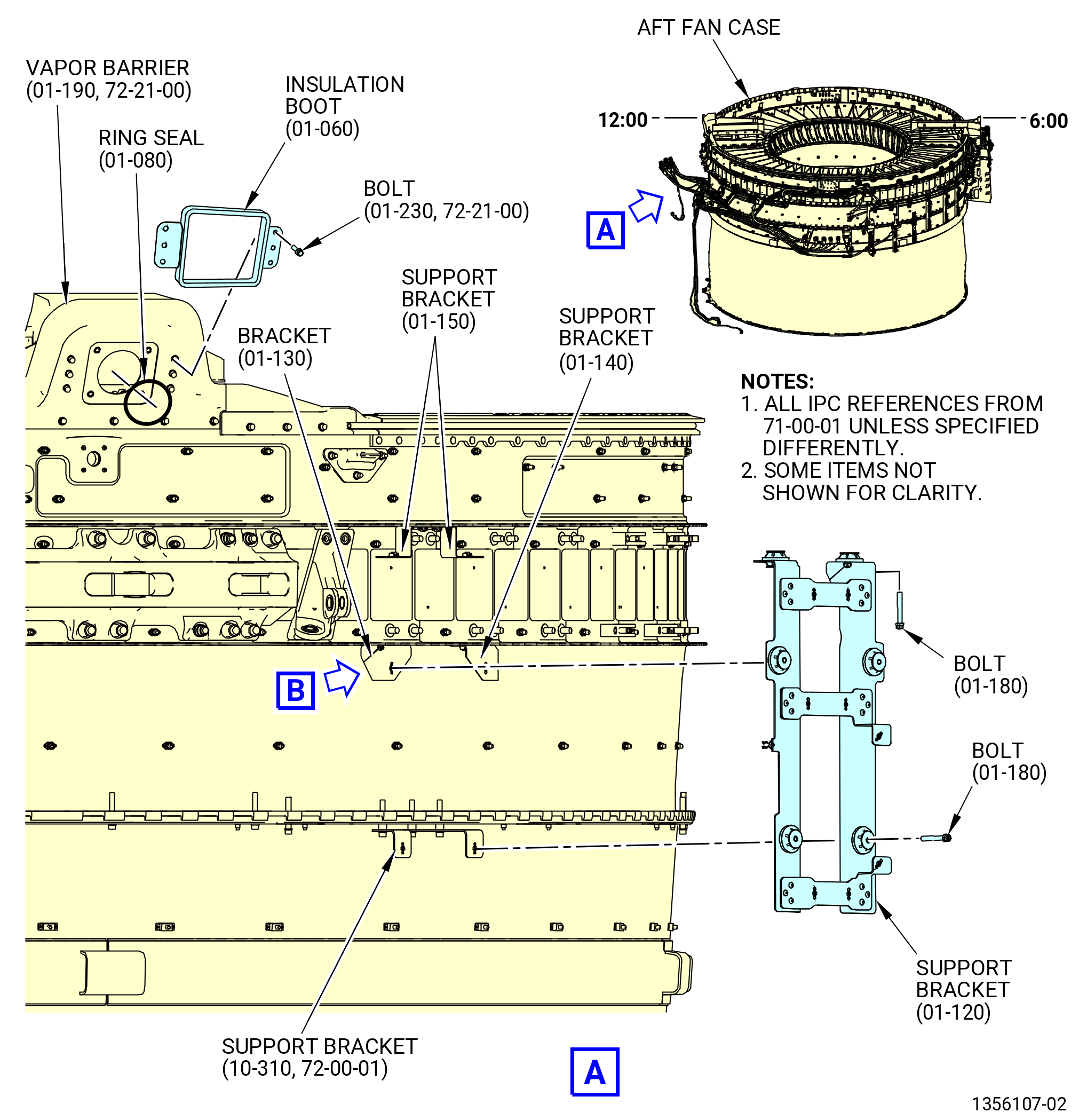
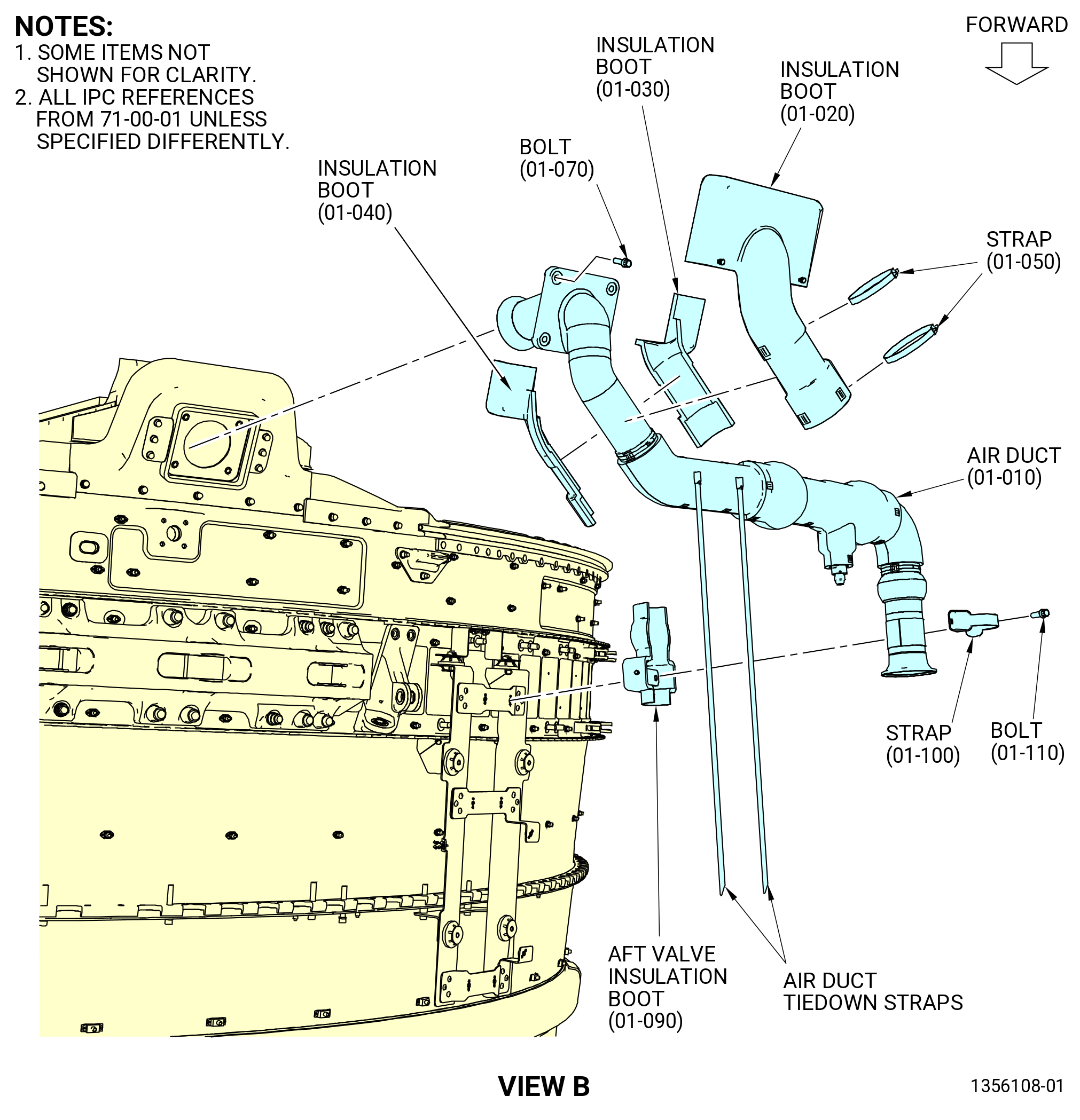
| D. | Remove the air duct (01-010 , 71-00-01) (SIN 6100B) from the aft fan case. Refer to Figure 508 and do as follows: |
| (1) | Remove and discard the safety cable from the firewall insulation boot (insulation boot) (01-020 , 71-00-01) (SIN 6109A). |
| (2) | Remove and discard the tiedown straps (straps) (01-050 , 71-00-01) (SIN 61087) from the insulation boots (01-020 , 71-00-01) (SIN 6109A), (01-030 , 71-00-01) (SIN 61098), and (01-040 , 71-00-01) (SIN 6109J). |
| (3) | Remove the insulation boots (01-020 , 71-00-01) (SIN 6109A), (01-030 , 71-00-01) (SIN 61098), and (01-040 , 71-00-01) (SIN 6109J). |
| (4) | Remove the machine bolts (bolts) (01-110 , 71-00-01) (SIN 61025), retaining strap (strap) (01-100 , 71-00-01) (SIN 61085), and aft valve insulation boot (01-090 , 71-00-01) (SIN 61093) from the air duct forward end. |
| (5) | Remove the machine bolts (bolts) (01-070 , 71-00-01) (SIN 61029), at four locations, from the aft end of the air duct that is attached to the vapor barrier (01-190 , 72-21-00) (SIN 84405). |
| (6) | Remove the air duct and ring seal (01-080 , 71-00-01) (SIN 61053) from the aft fan case. |
| (7) | Remove the shear bolts (bolts) (01-230 , 72-21-00) (SIN 84421) and firewall insulation boot (insulation boot) (01-060 , 71-00-01) (SIN 61092) from the OGV fairing. |
| (8) | Remove the machine bolts (bolts) (01-180 , 71-00-01) (SIN 6102B) that attach the engine anti-icing (EAI) fan case support bracket (support bracket) (01-120 , 71-00-01) (SIN 6101D) to the support brackets (01-130 , 71-00-01) (SIN 6101E), (01-140 , 71-00-01) (SIN 6101G), (01-150 , 71-00-01) (SIN 6101Z), and (10-310) (SIN 6101F). |
| (9) | Remove the support bracket (01-120 , 71-00-01) (SIN 6101D) from the aft fan case. |
| Subtask 72-00-01-040-053 |
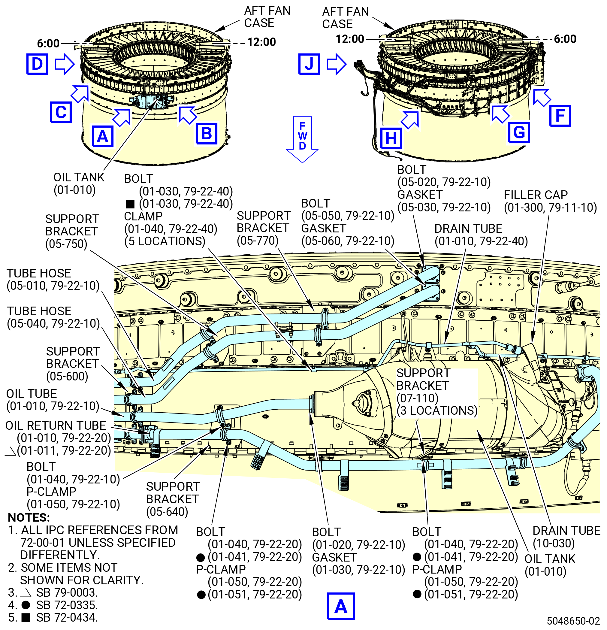
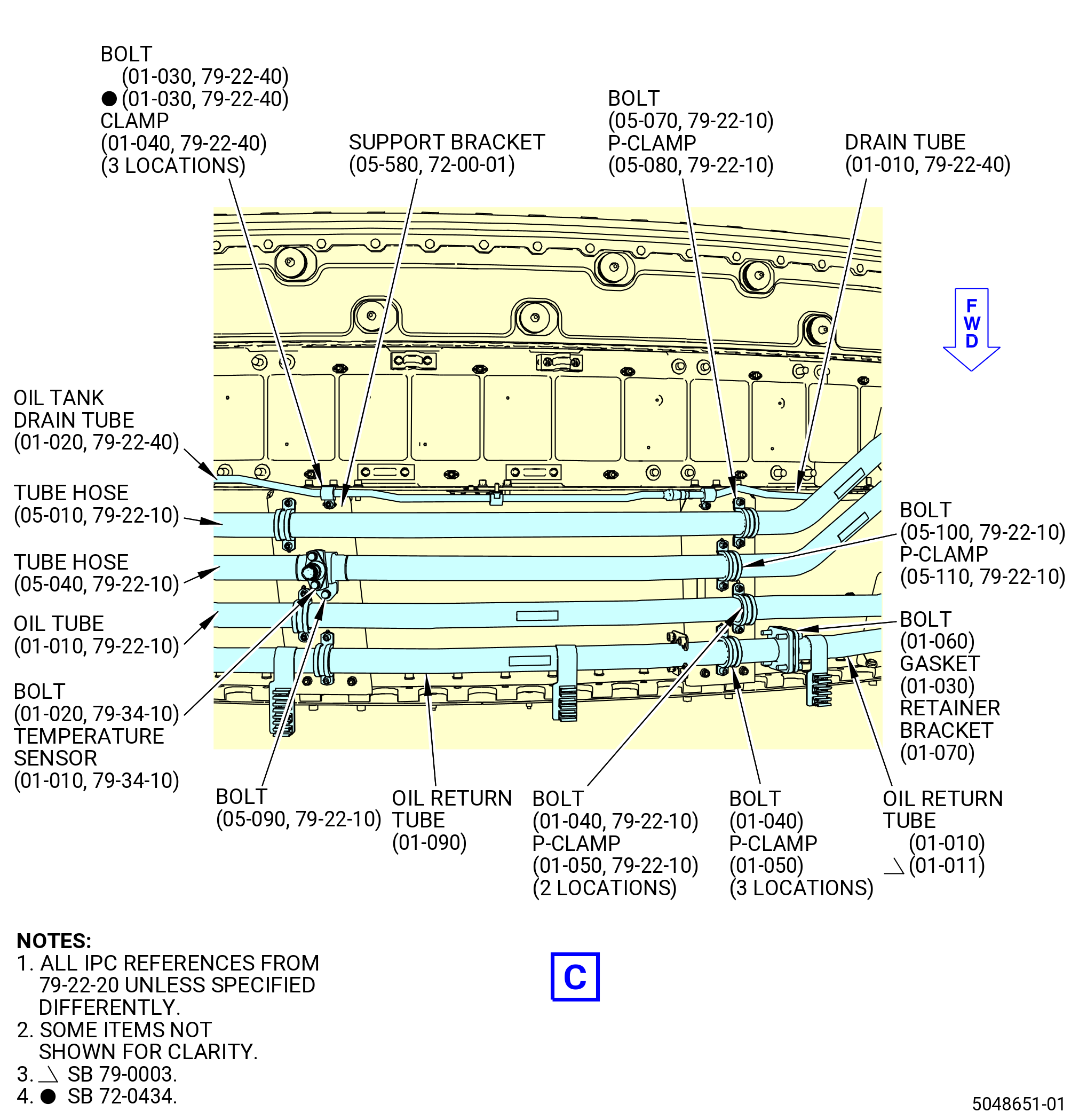
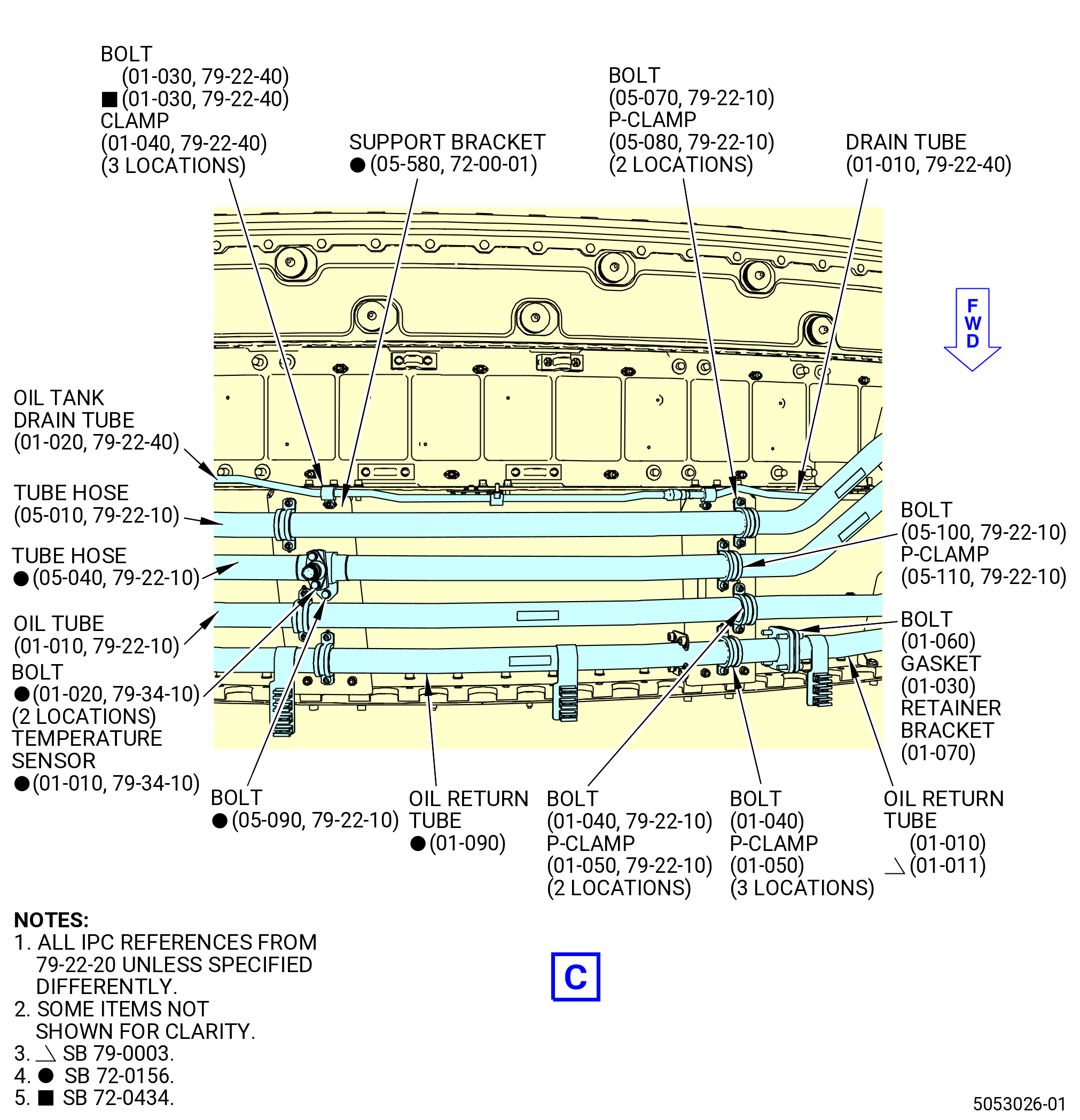
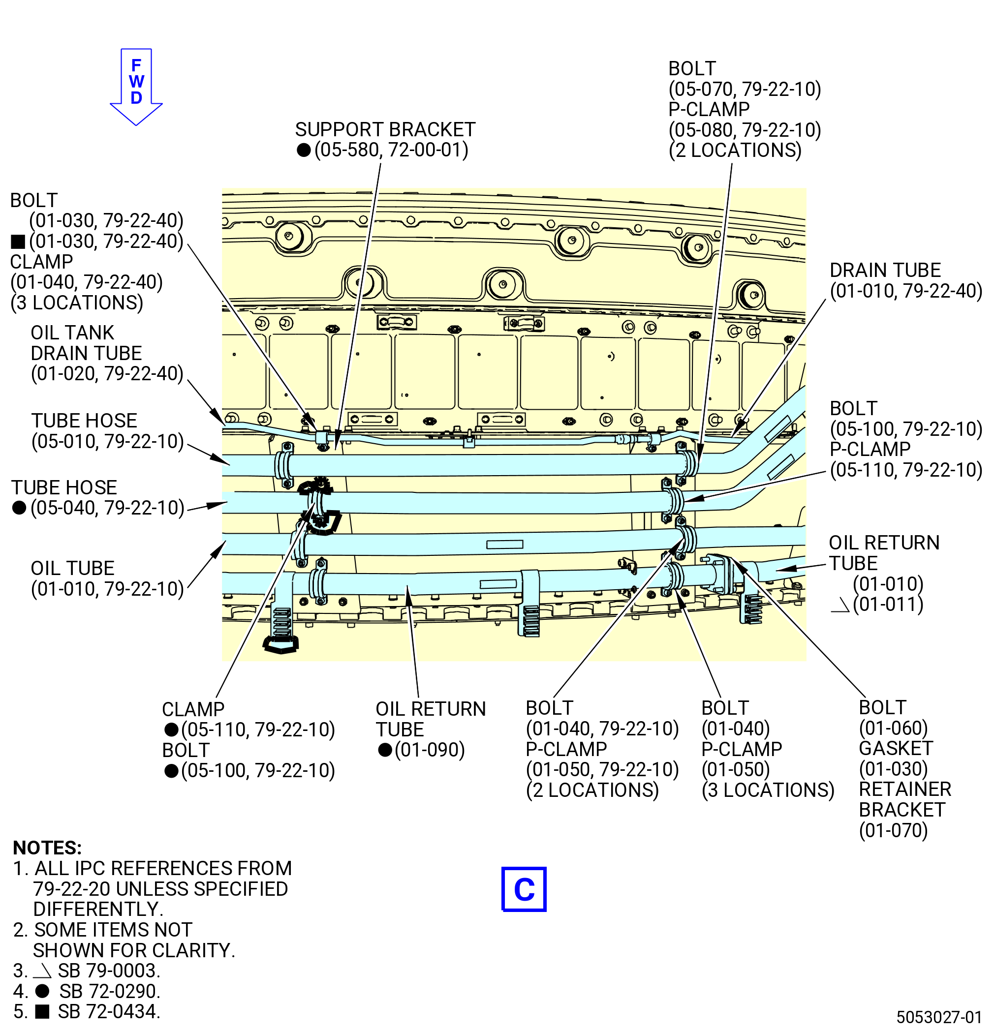
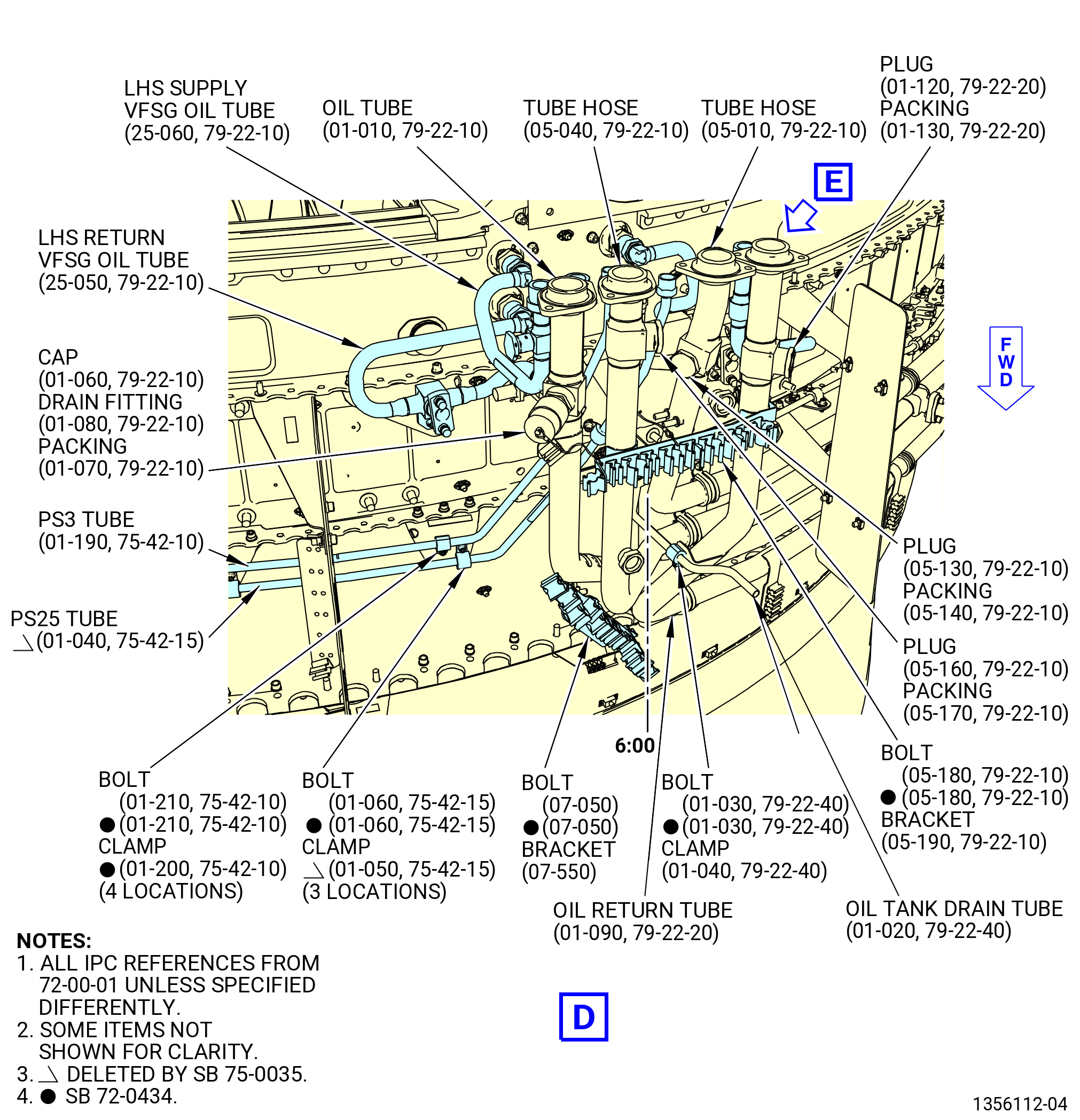
| E. | Remove the oil and air lines from the oil tank (01-010) (SIN 00400) and the aft fan case. Refer to Figure 509 and do as follows: |
| (1) | Remove the drain fitting (01-080 , 79-22-10) (SIN 44060) and machine plugs (plugs) (05-130 , 79-22-10) (SIN 44860), (05-160 , 79-22-10) (SIN 44960), and (01-120 , 79-22-20) (SIN 45360) from the oil tube (01-010 , 79-22-10) (SIN 44000), tube hose (05-010 , 79-22-10) (SIN 44801) and (05-040 , 79-22-10) (SIN 44900), and oil return tube (01-090 , 79-22-20) (SIN 45302) as follows: |
| (a) | Remove and discard the safety cable from the drain fitting and plugs. |
| (b) | Remove the drain fitting and plugs from the oil supply tube, tube hoses, and oil return tube. |
| (c) | Remove and discard the packings (01-070 , 79-22-10) (SIN 44050), (05-140 , 79-22-10) (SIN 44853), (05-170 , 79-22-10) (SIN 44951), and (01-130 , 79-22-20) (SIN 45354) from the drain fitting and plugs. |
| (2) | Remove the oil tank drain tube (drain tube) (01-010 , 79-22-40) (SIN 48500) from the oil tank as follows: |
| (a) | Disconnect the drain tube B-nuts that connect the oil tank and the drain tube. |
| (b) | Remove the bolts (01-030 , 79-22-40) (SIN 48520) and cushion loop clamps (clamps) (01-040 , 79-22-40) (SIN 48580) that connect the drain tube to the brackets at five locations. |
| (c) | Remove the drain tube from the oil tank and aft fan case. |
| (3) | Remove the oil tube (01-010 , 79-22-10) (SIN 44000) from the oil tank as follows: |
| (a) | Remove the machine bolts (bolts) (01-020 , 79-22-10) (SIN 44020) that attach the oil tube to the oil tank at four locations. |
| (b) | Remove and discard the flange seal gasket (gasket) (01-030 , 79-22-10) (SIN 44051). |
| (c) | Remove the bolts (01-040 , 79-22-10) (SIN 44023) and P-clamps (01-050 , 79-22-10) (SIN 44080) that attach the oil supply tube to the aft fan case at three locations. |
| (d) | Remove the oil supply tube from the oil tank and aft fan case. |
| Subtask 72-00-01-040-067 |
| * * * PRE SB 79-0003( Oil Return Tube with Small Clearance ) |
| (4) | Remove the oil return tube (01-010 , 79-22-20) (SIN 45304) from the oil tank (01-010) (SIN 00400) as follows: |
| (a) | Remove the machine bolts (bolts) (01-020 , 79-22-20) (SIN 45320) that attach the oil return tube (01-010 , 79-22-20) (SIN 45304) to the lubriclone assembly (lubriclone) (01-010 , 79-21-20) (SIN 400A1) at four locations. |
| (b) | Remove and discard the flange seal gasket (gasket) (01-030 , 79-22-20) (SIN 45351). |
| (c) | Remove the bolts (01-040 , 79-22-20) (SIN 45323) and P-clamps (01-050 , 79-22-20) (SIN 45381) that attach the oil return tube (01-010 , 79-22-20) (SIN 45304) to the aft fan case at four locations. |
| (d) | Remove the machine bolts (bolts) (01-060 , 79-22-20) (SIN 45321) and retainer brackets (01-070 , 79-22-20) (SIN 45314) that attach the oil return tube (01-010 , 79-22-20) (SIN 45304) to the oil return tube (01-090 , 79-22-20) (SIN 45302). |
| (e) | Remove and discard the gasket (01-030 , 79-22-20) (SIN 45351). |
| (f) | Remove the oil return tube (01-010 , 79-22-20) (SIN 45304) from the aft fan case. |
| * * * END PRE SB 79-0003( ) |
| Subtask 72-00-01-040-068 |
| * * * PRE SB 72-0335( Increased Assembly Time Configuration ) |
| * * * SB 79-0003( Oil Return Tube with More Clearance ) |
| (4).A. | Remove the oil return tube (01-011 , 79-22-20) (SIN 45304) from the oil tank (01-010) (SIN 00400) as follows: |
| (a) | Remove the bolts (01-020 , 79-22-20) (SIN 45320) that attach the oil return tube (01-011 , 79-22-20) (SIN 45304) to the lubriclone (01-010 , 79-21-20) (SIN 400A1) at four locations. |
| (b) | Remove and discard the gasket (01-030 , 79-22-20) (SIN 45351). |
| (c) | Remove the bolts (01-040 , 79-22-20) (SIN 45323) and P-clamp (01-050 , 79-22-20) (SIN 45381) that attach the oil return tube (01-011 , 79-22-20) (SIN 45304) to the support bracket (bracket) (01-140 , 79-22-20) (SIN 45312) on the aft fan case. |
| (d) | Remove the bolts (01-040 , 79-22-20) (SIN 45323) and P-clamps (01-050 , 79-22-20) (SIN 45381) that attach the oil return tube (01-011 , 79-22-20) (SIN 45304) to the brackets on the aft fan case at four locations. |
| (e) | Remove the bolts (01-060 , 79-22-20) (SIN 45321) and retainer brackets (01-070 , 79-22-20) (SIN 45314) that attach the oil return tube (01-011 , 79-22-20) (SIN 45304) to the oil return tube (01-090 , 79-22-20) (SIN 45302). |
| (f) | Remove and discard the gasket (01-030 , 79-22-20) (SIN 45351). |
| (g) | Remove the oil return tube (01-011 , 79-22-20) (SIN 45304) from the aft fan case. |
| * * * END SB 79-0003 |
| * * * END PRE SB 72-0335 |
| Subtask 72-00-01-040-081 |
| * * * SB 72-0335( Increased Assembly Time Configuration ) |
| (4).B. | Remove the oil return tube (01-011 , 79-22-20) (SIN 45304) from the oil tank (01-010) (SIN 00400) as follows: |
| (a) | Remove the bolts (01-020 , 79-22-20) (SIN 45320) that attach the oil return tube (01-011 , 79-22-20) (SIN 45304) to the lubriclone (01-010 , 79-21-20) (SIN 400A1) at four locations. |
| (b) | Remove and discard the gasket (01-030 , 79-22-20) (SIN 45351). |
| (c) | Remove the machine bolts (bolts) (01-041 , 79-22-20) (SIN 45323) and cushioned clamp (P-clamp) (01-051 , 79-22-20) (SIN 45381) that attach the oil return tube (01-011 , 79-22-20) (SIN 45304) to the support bracket (bracket) (01-140 , 79-22-20) (SIN 45312) on the aft fan case. |
| (d) | Remove the bolts (01-041 , 79-22-20) (SIN 45323) and P-clamps (01-051 , 79-22-20) (SIN 45381) that attach the oil return tube (01-011 , 79-22-20) (SIN 45304) to the brackets on the aft fan case at four locations. |
| (e) | Remove the bolts (01-060 , 79-22-20) (SIN 45321) and retainer brackets (01-070 , 79-22-20) (SIN 45314) that attach the oil return tube (01-011 , 79-22-20) (SIN 45304) to the oil return tube (01-090 , 79-22-20) (SIN 45302). |
| (f) | Remove and discard the gasket (01-030 , 79-22-20) (SIN 45351). |
| (g) | Remove the oil return tube (01-011 , 79-22-20) (SIN 45304) from the aft fan case. |
| * * * END SB 72-0335 |
|
|
|
|
|
|
| Subtask 72-00-01-040-054 |
| (5) | Remove the tube hose (05-040 , 79-22-10) (SIN 44900) from the support brackets (05-770) (SIN 44815), (05-750) (SIN 44814), and (05-600) (SIN 44011) at two positions as follows: |
| Subtask 72-00-01-040-076 |
| * * * FOR 1B/P/G03.1B/P/G04.1B/P1/G01 |
| * * * PRE SB 72-0290( Engines with Temperature Sensor ) |
| (6) | Remove the bolts (01-020 , 79-34-10) (SIN 44921), (05-090 , 79-22-10) (SIN 44921), and (05-100 , 79-22-10) (SIN 44923) as follows: |
| NOTE: |
|
| (a) | Remove the machine bolts (bolts) (01-020 , 79-34-10) (SIN 44921) that attach the temperature sensor (01-010 , 79-34-10) (SIN 40800) to the tube hose. |
| (b) | Remove the temperature sensor. |
| * * * END PRE SB 72-0290 |
| Subtask 72-00-01-040-080 |
| * * * FOR ALL PIP 2 |
| * * * SB 72-0156( Engine with Temperature Sensor ) |
| (6).A. | Remove the bolts (01-020 , 79-34-10) (SIN 44921), (05-090 , 79-22-10) (SIN 44921), and (05-100 , 79-22-10) (SIN 44923) as follows: |
| NOTE: |
|
| (a) | Remove the bolts (01-020 , 79-34-10) (SIN 44921) that attach the temperature sensor (01-010 , 79-34-10) (SIN 40800) to the tube hose. |
| (b) | Remove the temperature sensor. |
| * * * END SB 72-0156( ) |
| Subtask 72-00-01-040-077 |
| * * * FOR ALL |
| * * * SB 72-0156( Engine with Temperature Sensor ) |
| * * * PRE SB 72-0290( Engines with Temperature Sensor ) |
| (c) | Remove the bolts (05-090 , 79-22-10) (SIN 44921) and (05-100 , 79-22-10) (SIN 44923) and P-clamps (05-110 , 79-22-10) (SIN 44980) that attach the tube hose to the support brackets (05-770) (SIN 44815), (05-750) (SIN 44814), and (05-600) (SIN 44011) at two locations. |
| NOTE: |
|
| * * * END SB 72-0156 |
| * * * END PRE SB 72-0290 |
| Subtask 72-00-01-040-078 |
| * * * PRE SB 72-0156( Engine without Temperature Sensor ) |
| * * * SB 72-0290( Engines without Temperature Sensor ) |
| (c).A. | Remove the bolts (05-100 , 79-22-10) (SIN 44923) and P-clamps (05-110 , 79-22-10) (SIN 44980) that attach the tube hose to the support brackets (05-770) (SIN 44815), (05-750) (SIN 44814), and (05-600) (SIN 44011) at two locations, and (05-580) (SIN 44010) at five locations. |
| NOTE: |
|
| * * * END SB 72-0290 |
| * * * END PRE SB 72-0156 |
| Subtask 72-00-01-040-079 |
| (d) | Remove the bolts (05-050 , 79-22-10) (SIN 44920) that attach the tube hose to the heat exchanger inner connector at four locations. |
| (e) | Remove and discard the seal flange gasket (gasket) (05-060 , 79-22-10) (SIN 44950). |
| (f) | Remove the tube hose from the fan stator case. |
| (7) | Remove the tube hose (05-010 , 79-22-10) (SIN 44801) from the support brackets (05-770) (SIN 44815), (05-750) (SIN 44814), (05-600) (SIN 44011) at two positions, and (05-580) (SIN 44010) as follows: |
| (a) | Remove the bolts (05-070 , 79-22-10) (SIN 44823) and P-clamps (05-080 , 79-22-10) (SIN 44880) that attach the tube hose to the support brackets at five locations. |
| (b) | Remove the bolts (05-020 , 79-22-10) (SIN 44820) that attach the tube hose to the heat exchanger outer connector at four locations. |
| (c) | Remove and discard the flange seal gasket (gasket) (05-030 , 79-22-10) (SIN 44850). |
| (d) | Remove the tube hose from the support brackets. |
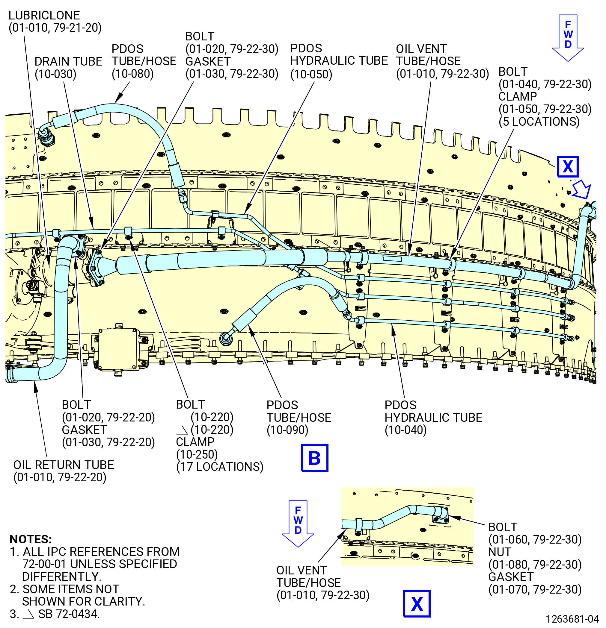
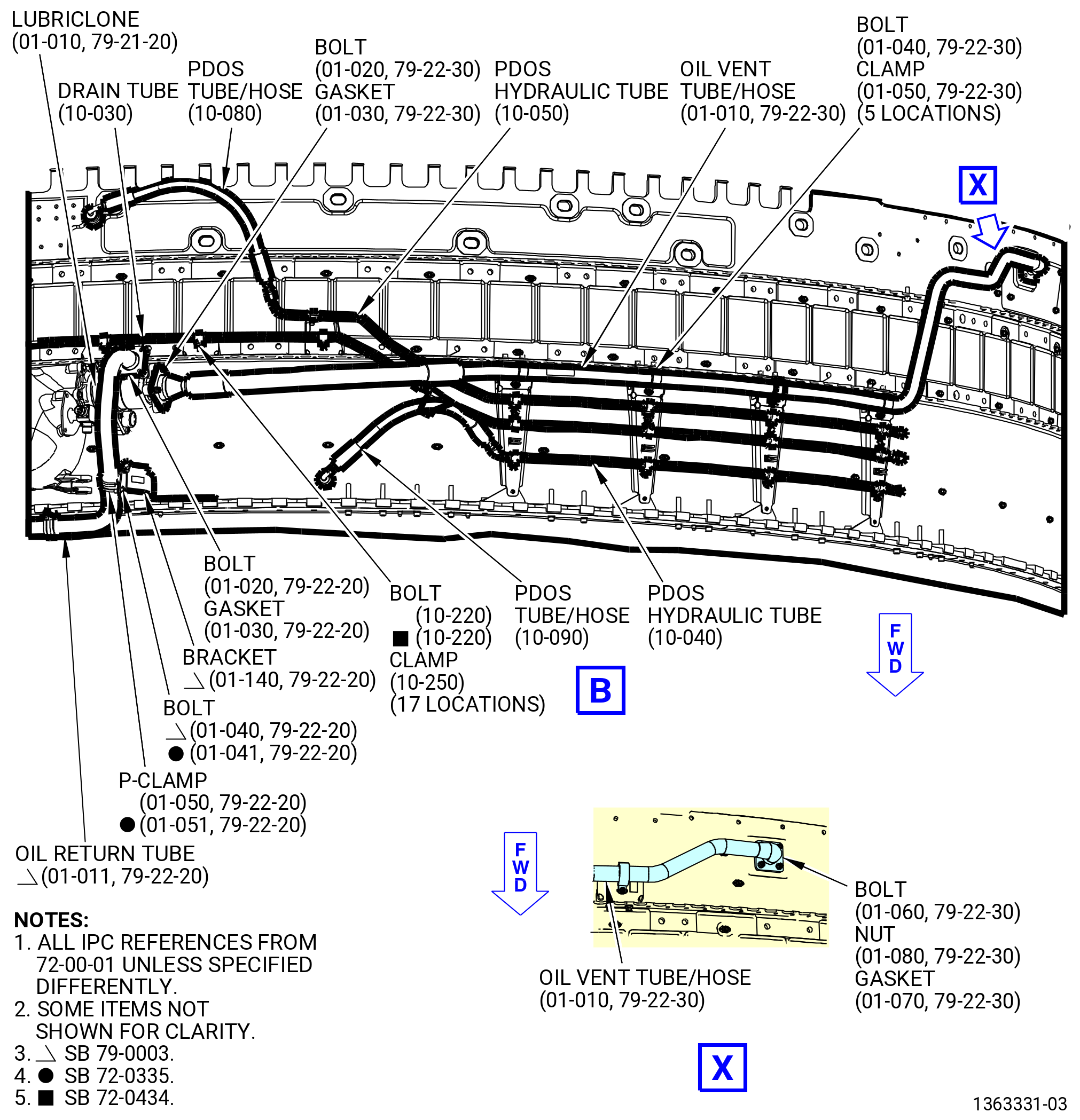
| (8) | Remove the PDOS drain hydraulic tube (drain tube) (10-030) (SIN 53302) from the fan stator case as follows: |
| (a) | Remove the machine bolts (bolts) (10-220) (SIN 53320) and cushion loop clamps (clamps) (10-250) (SIN 53380) that attach the drain tube to the fan stator case. |
| (b) | Remove the drain tube from the fan stator case. |
| (9) | Remove the PDOS hydraulic tube (10-050) (SIN 53304) and the PDOS tube hose assembly (PDOS tube/hose) (10-080) (SIN 53307) from the fan stator case as follows: |
| (a) | Disconnect the B-nut of the PDOS hydraulic tube that is attached to the PDOS tube/hose. |
| (b) | Remove the PDOS tube/hose. |
| (c) | Remove the bolts (10-220) (SIN 53320) and clamps (10-250) (SIN 53380) that attach the PDOS hydraulic tube to the fan stator case at six locations. |
| (d) | Remove the PDOS hydraulic tube from the fan stator case. |
| (10) | Remove the PDOS hydraulic tube (10-040) (SIN 53303) and the fan cowl right assembly PDOS tube hose (PDOS tube/hose) (10-090) (SIN 53308) from the fan stator case as follows: |
| (a) | Disconnect the B-nut of the PDOS tube/hose that is attached to the PDOS hydraulic tube. |
| (b) | Remove the PDOS tube/hose. |
| (c) | Remove the bolts (10-220) (SIN 53320) and clamps (10-250) (SIN 53380) that attach the PDOS hydraulic tube to the fan stator case at four locations. |
| (d) | Remove the PDOS hydraulic tube from the fan stator case. |
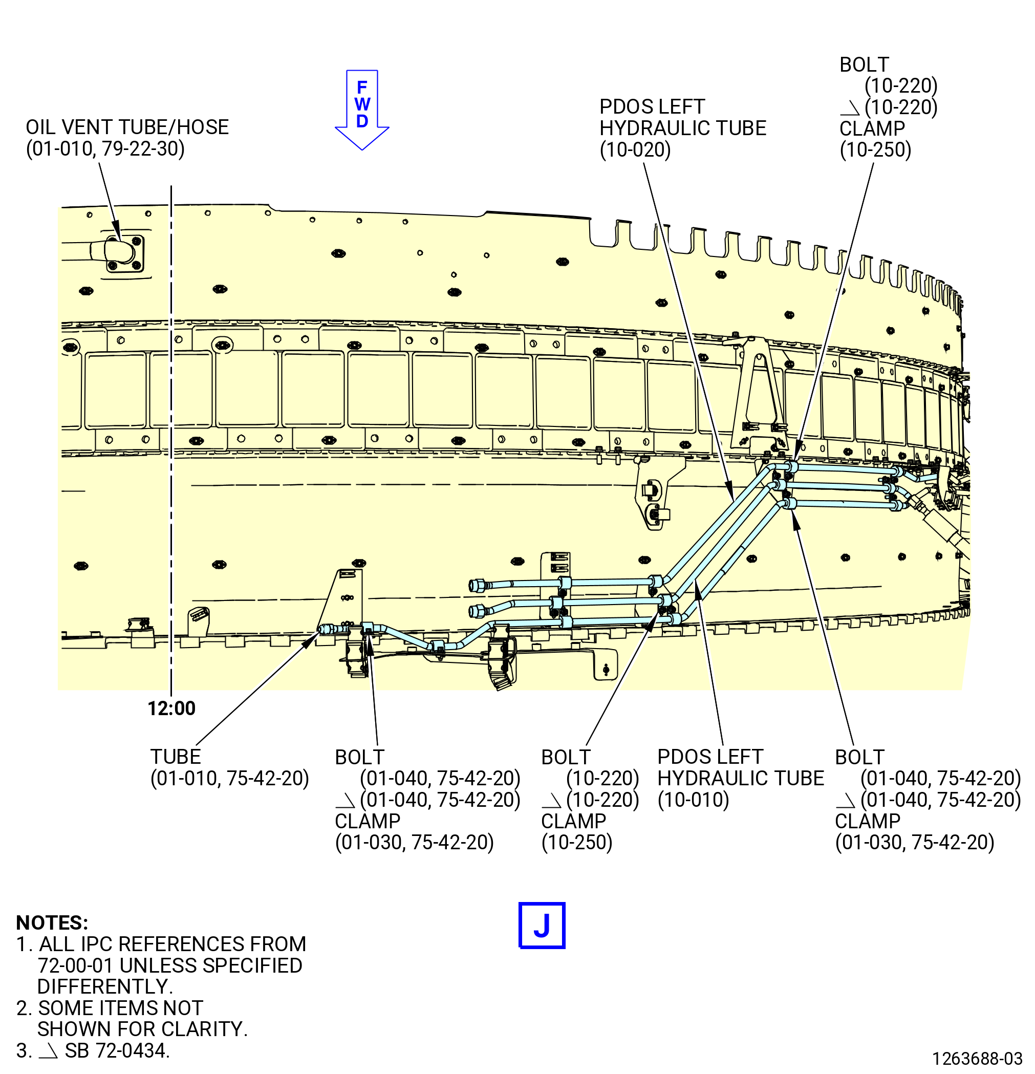
| (11) | Remove the oil vent tube/hose (01-010 , 79-22-30) (SIN 46000) from the lubriclone (01-010 , 79-21-20) (SIN 400A1) that is connected to the oil tank (01-010) (SIN 00400) as follows: |
| (a) | Remove the bolts (01-040 , 79-22-30) (SIN 46024) and cushion loop clamps (clamps) (01-050 , 79-22-30) (SIN 46081) from the oil vent tube/hose at five locations. |
| (b) | Remove the machine bolts (bolts) (01-060 , 79-22-30) (SIN 46026) and self-locking nuts (nuts) (01-080 , 79-22-30) (SIN 46040) that attach the oil vent tube/hose to the aft fan case at the 12:00 o'clock position. |
| (c) | Remove and discard the flange seal gasket (gasket) (01-070 , 79-22-30) (SIN 46053). |
| (d) | Remove the machine bolts (bolts) (01-020 , 79-22-30) (SIN 46027) that attach the oil vent tube/hose to the lubriclone on the oil tank. |
| (e) | Remove and discard the flange seal gasket (gasket) (01-030 , 79-22-30) (SIN 46050). |
| (f) | Remove the oil vent tube/hose from the fan stator case. |
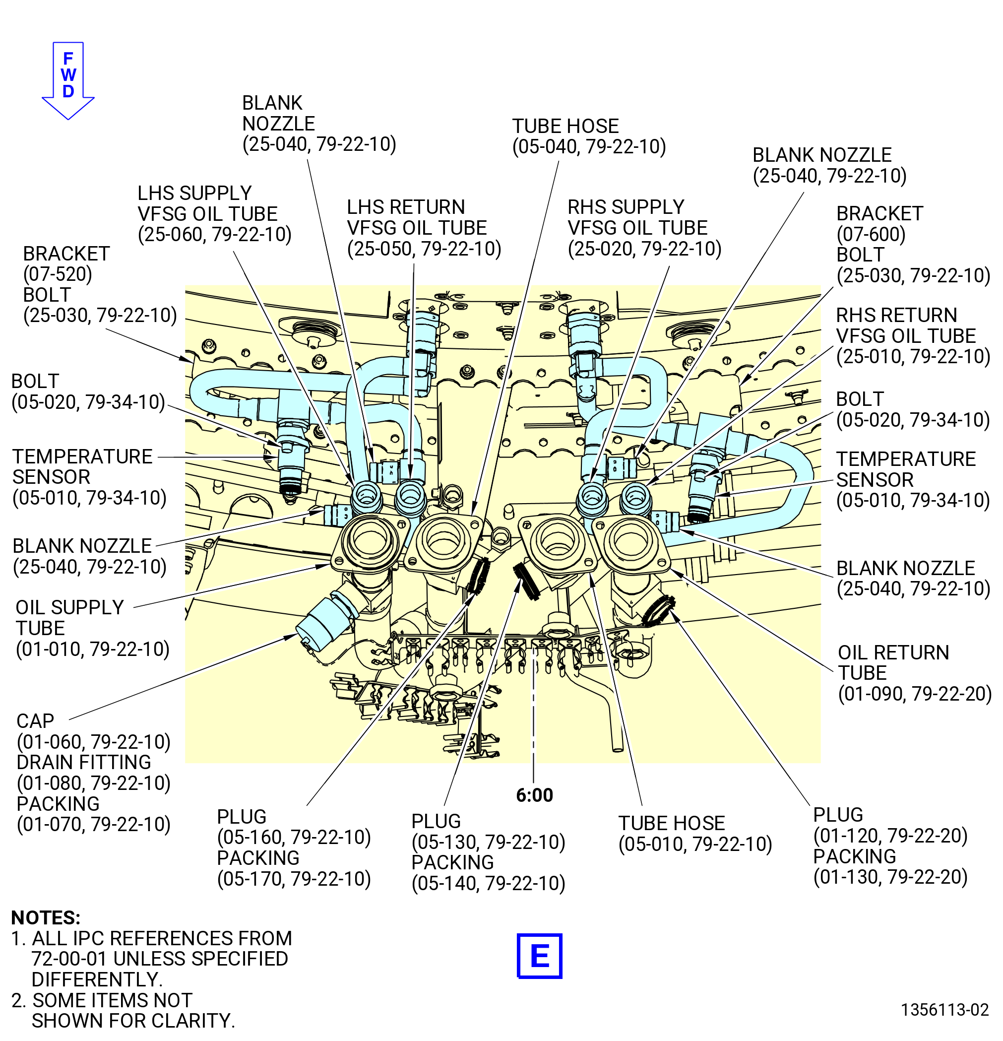
| (12) | Remove the blank nozzles (25-040 , 79-22-10) (SIN 52160) from the LHS supply VFSG oil tube (25-060 , 79-22-10) (SIN 5210C), LHS return VFSG oil tube (25-050 , 79-22-10) (SIN 5210D), RHS supply VFSG oil tube (25-020 , 79-22-10) (SIN 5210E), and RHS return VFSG oil tube (25-010 , 79-22-10) (SIN 5210F). |
| (13) | Remove the RHS supply VFSG oil tube (25-020 , 79-22-10) (SIN 5210E) and RHS return VFSG oil tube (25-010 , 79-22-10) (SIN 5210F) as follows: |
| (a) | Remove the hex bolts (bolts) (05-020 , 79-34-10) (SIN 65T24) that attach the fuel/oil temperature sensor (temperature sensor) (05-010 , 79-34-10) (SIN 65T03) to the RHS return VFSG oil tube (25-010 , 79-22-10) (SIN 5210F). |
| (b) | Remove the temperature sensor. |
| (c) | Remove the machine bolt (bolt) (25-030 , 79-22-10) (SIN 52123) that attaches the VFSG oil tube to the bracket (07-600) (SIN 5211F). |
| (d) | Disconnect and remove the VFSG oil tube from the VFSG heat exchanger (05-030 , 79-21-00) (SIN 52101). |
| (e) | Disconnect and remove the RHS supply VFSG oil tube (25-020 , 79-22-10) (SIN 5210E) from the VFSG heat exchanger. |
| (14) | Remove the LHS supply VFSG oil tube (25-060 , 79-22-10) (SIN 5210C) and LHS return VFSG oil tube (25-050 , 79-22-10) (SIN 5210D) as follows: |
| (a) | Remove the bolts (05-020 , 79-34-10) (SIN 65T24) that attach the temperature sensor (05-010 , 79-34-10) (SIN 65T03) to the LHS return VFSG oil tube (25-050 , 79-22-10) (SIN 5210D). |
| (b) | Remove the temperature sensor. |
| (c) | Remove the bolt (25-030 , 79-22-10) (SIN 52123) that attaches the VFSG oil tube to the bracket (07-520) (SIN 5211Y). |
| (d) | Disconnect and remove the VFSG oil tube from the VFSG heat exchanger (05-040 , 79-21-00) (SIN 52100). |
| (e) | Disconnect and remove the LHS supply VFSG oil tube (25-060 , 79-22-10) (SIN 5210C) from the VFSG heat exchanger. |
| (15) | Remove the oil tank drain tube (01-020 , 79-22-40) (SIN 48501) from the bracket on the oil return tube (01-090 , 79-22-20) (SIN 45302) as follows: |
| (a) | Remove the bolt (01-030 , 79-22-40) (SIN 48520) and clamp (01-040 , 79-22-40) (SIN 48580) from the bracket on the oil return tube. |
| (16) | Remove the oil tank drain tube (01-020 , 79-22-40) (SIN 48501) from the fan stator case as follows: |
| (a) | Disconnect the B-nut of the oil tank drain tube from the drain tube (01-010 , 79-22-40) (SIN 48500). |
| (b) | Remove the bolts (01-030 , 79-22-40) (SIN 48520) and clamps (01-040 , 79-22-40) (SIN 48580) from the oil tank drain tube at four locations. |
| (c) | Remove the oil tank drain tube from the fan stator case. |
| (17) | Remove the oil return tube (01-090 , 79-22-20) (SIN 45302) from the fan stator case as follows: |
| (a) | Remove the bolts (01-040 , 79-22-20) (SIN 45323) and P-clamps (01-050 , 79-22-20) (SIN 45381) from the oil return tube at three locations. |
| (b) | Remove the oil return tube. |
| (18) | Remove the machine bolt (07-050) (SIN 67021) and electrical bracket (bracket) (07-550) (SIN 67019) that are attached to the bracket on the oil tube (01-010 , 79-22-10) (SIN 44000). |
| (19) | Remove the bolts (05-180 , 79-22-10) (SIN 67021) and bracket (05-190 , 79-22-10) (SIN 67018) that is attached to the brackets on the tube hose (05-040 , 79-22-10) (SIN 44900) and oil return tube (01-090 , 79-22-20) (SIN 45302) at two locations. |
| Subtask 72-00-01-040-082 |
| * * * PRE SB 75-0035( Engines with PS25 Pressure Sense Tube and Air P25 Hose Tube ) |
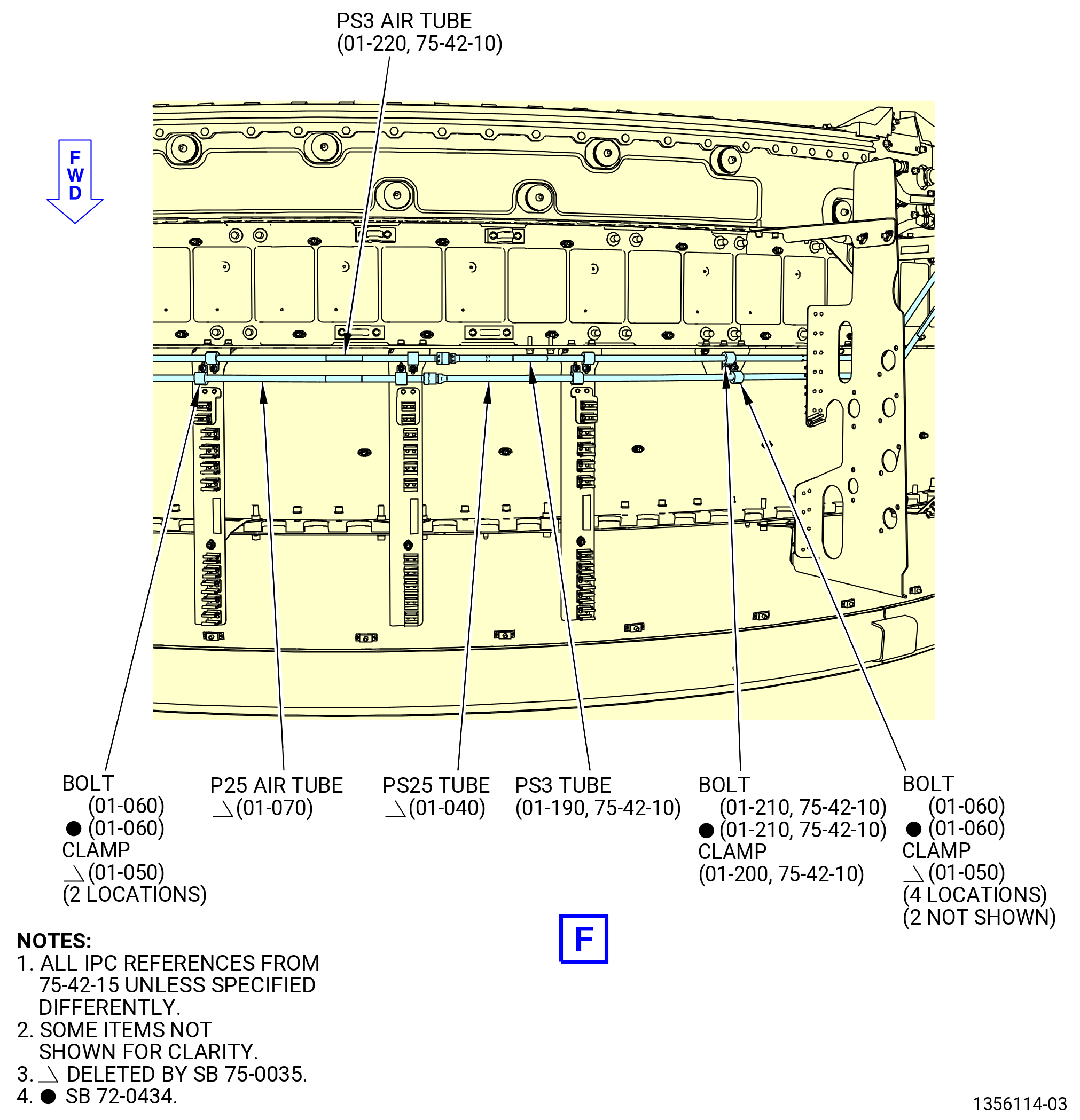
| (20) | Remove the air P25 tube hose (P25 air tube) (01-070 , 75-42-15) (SIN 61402) from the fan stator case as follows: |
| (a) | Disconnect the B-nut of the P25 air tube from the pressure sense PS25 tube (PS25 tube) (01-040 , 75-42-15) (SIN 61401). |
| (b) | Remove the machine bolts (bolts) (01-060 , 75-42-15) (SIN 61420) and cushion loop clamps (clamps) (01-050 , 75-42-15) (SIN 61480) from the P25 air tube. |
| (c) | Remove the P25 air tube from the fan stator case. |
| * * * END PRE SB 75-0035 |
| Subtask 72-00-01-040-083 |
| * * * SB 75-0035( Engines without PS25 Pressure Sense Tube and Air P25 Hose Tube ) |
| (20).A. | Remove the five bolts (01-060 , 75-42-15) (SIN 61420) from the two brackets (01-300) (SIN 61419) and three brackets (05-170) (SIN 61414). |
| * * * END SB 75-0035 |
| Subtask 72-00-01-040-084 |
| * * * PRE SB 75-0035( Engines with PS25 Pressure Sense Tube and Air P25 Hose Tube ) |
| (21) | Remove the PS25 pressure sense tube (PS25 tube) (01-040 , 75-42-15) (SIN 61401) from the fan stator case as follows: |
| (a) | Remove the bolts (01-060 , 75-42-15) (SIN 61420) and clamps (01-050 , 75-42-15) (SIN 61480) from the PS3 tube at four locations. |
| (b) | Remove the PS25 tube from the fan stator case. |
| * * * END PRE SB 75-0035 |
| Subtask 72-00-01-040-085 |
| * * * SB 75-0035( Engines without PS25 Pressure Sense Tube and Air P25 Hose Tube ) |
| (21).A. | Remove the four bolts (01-060 , 75-42-15) (SIN 61420) from the brackets (01-430) (SIN 61417), (01-410) (SIN 61418), (05-680) (SIN 61412), and (01-300) (SIN 61419). |
| * * * END SB 75-0035 |
| Subtask 72-00-01-040-086 |
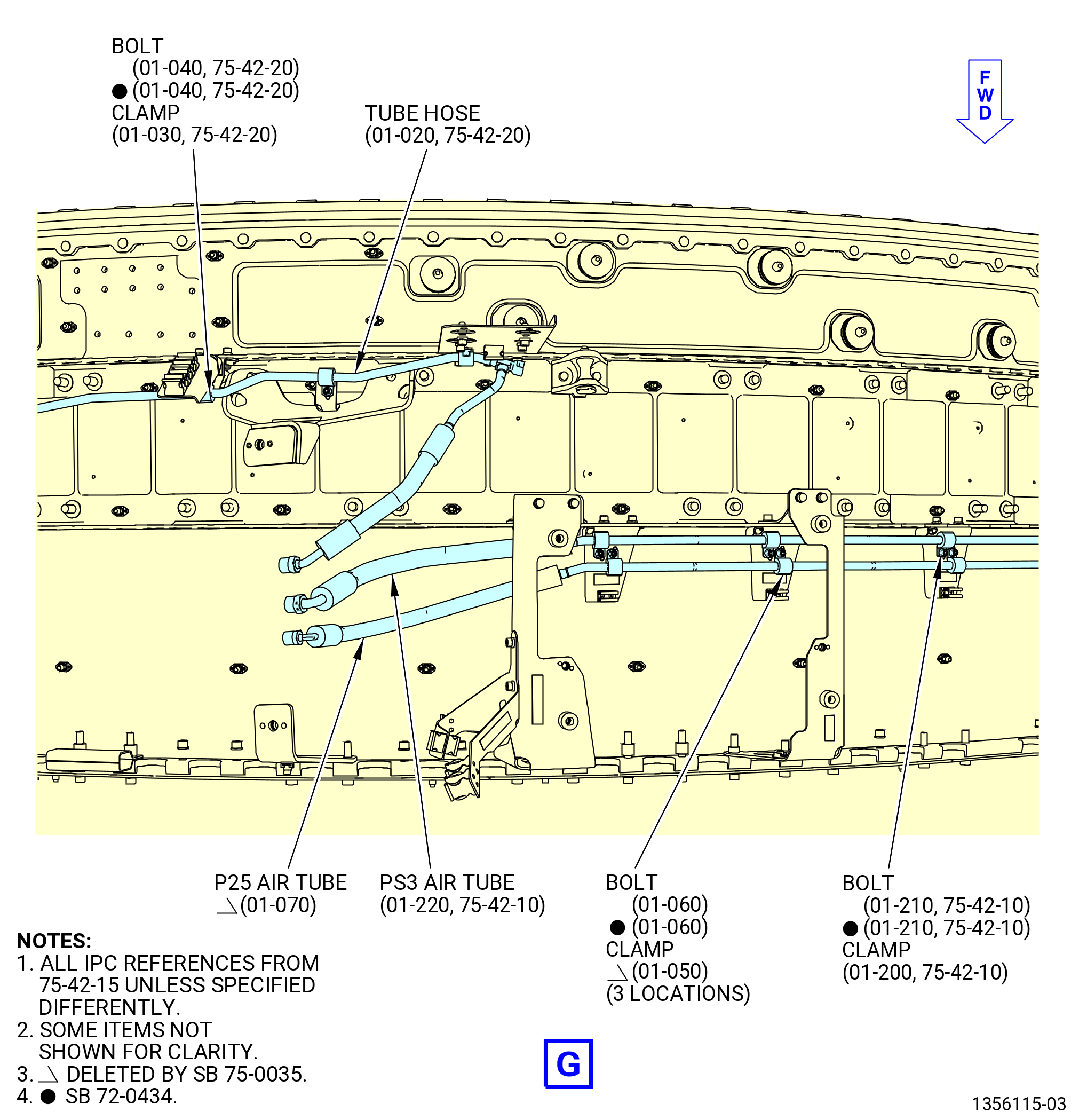
| (22) | Remove the PS3 air tube hose (PS3 air tube) (01-220 , 75-42-10) (SIN 61503) from the fan stator case as follows: |
| (a) | Disconnect the B-nut of the PS3 air tube from the pressure sense PS3 tube (PS3 tube) (01-190 , 75-42-10) (SIN 61502). |
| (b) | Remove the machine bolts (bolts) (01-210 , 75-42-10) (SIN 61520) and cushion loop clamps (clamps) (01-200 , 75-42-10) (SIN 61580) from the PS3 air tube. |
| (c) | Remove the PS3 air tube from the fan stator case. |
| (23) | Remove the PS3 tube (01-190 , 75-42-10) (SIN 61502) from the fan stator case as follows: |
| (a) | Remove the bolts (01-210 , 75-42-10) (SIN 61520) and clamps (01-200 , 75-42-10) (SIN 61580) from the PS3 tube at four locations. |
| (b) | Remove the PS3 tube from the fan stator case. |
| (c) | Deleted. |
| (d) | Deleted. |
| (24) | Remove the tube (01-010 , 75-42-20) (SIN 61300) from the fan stator case as follows: |
| (a) | Disconnect the B-nut of the PO pressure sense tube from the tube hose (01-020 , 75-42-20) (SIN 61301). |
| (b) | Remove the machine bolt (bolt) (01-040 , 75-42-20) (SIN 61320) and cushion loop clamps (clamps) (01-030 , 75-42-20) (SIN 61380) from the PO pressure sense tube. |
| (c) | Remove the PO pressure sense tube from the fan stator case. |
| (25) | Remove the tube hose (01-020 , 75-42-20) (SIN 61301) from the fan stator case as follows: |
| (a) | Remove the bolts (01-040 , 75-42-20) (SIN 61320) and clamps (01-030 , 75-42-20) (SIN 61380) from the tube hose. |
| (b) | Remove the tube hose from the fan stator case. |
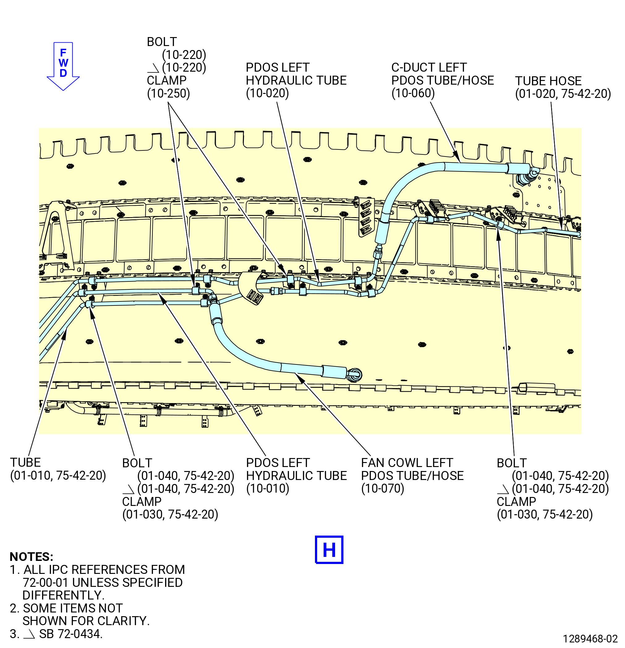
| (26) | Remove the PDOS left hydraulic tube (10-010) (SIN 53300) and the fan cowl left PDOS tube/hose (10-070) (SIN 53306) from the fan stator case as follows: |
| (a) | Disconnect the PDOS left hydraulic tube B-nut from the fan cowl left PDOS tube/hose. |
| (b) | Remove the fan cowl left PDOS tube/hose. |
| (c) | Remove the bolts (10-220) (SIN 53320) and clamps (10-250) (SIN 53380) from the PDOS left hydraulic tube. |
| (d) | Remove the PDOS left hydraulic tube from the fan stator case. |
| (27) | Remove the PDOS left hydraulic tube (10-020) (SIN 53301) and the C-duct left PDOS tube/hose (10-060) (SIN 53305) from the fan stator case as follows: |
| (a) | Disconnect the B-nut of the PDOS left hydraulic tube from the C-duct left PDOS tube/hose. |
| (b) | Remove the C-duct left PDOS tube/hose from the fan stator case. |
| (c) | Remove the bolts (10-220) (SIN 53320) and clamps (10-250) (SIN 53380) from the PDOS left hydraulic tube. |
| (d) | Remove the PDOS left hydraulic tube from the fan stator case. |
| (28) | Remove the 11C4593 surface cooler cover. |
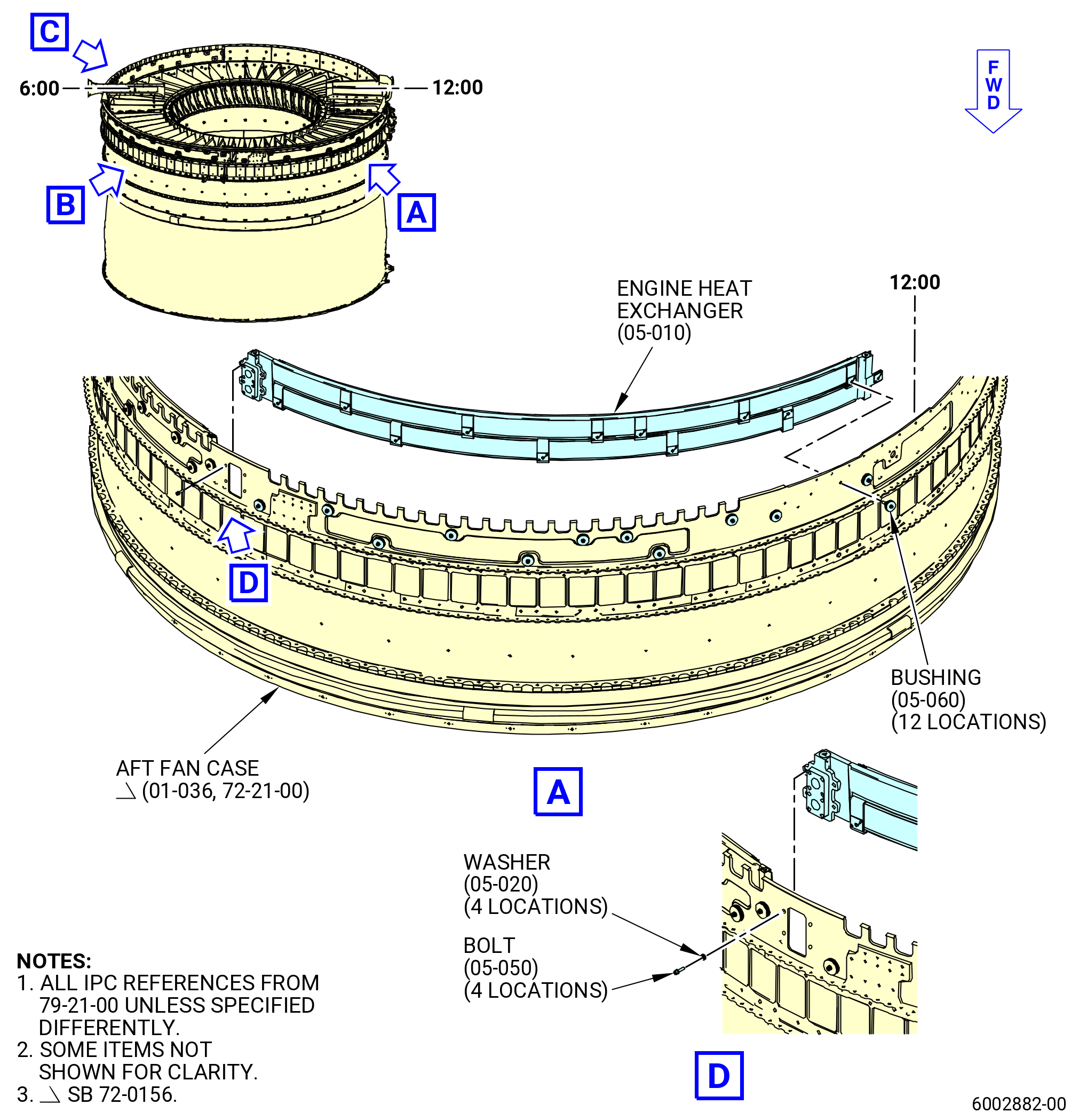
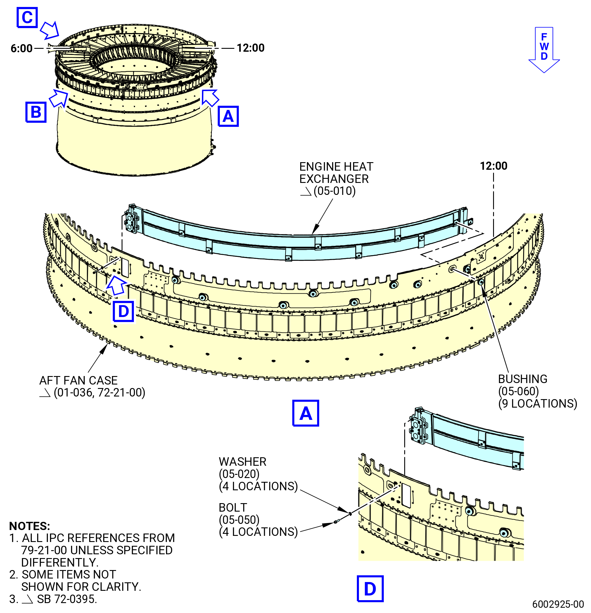
| (29) | Remove the engine heat exchanger (05-010 , 79-21-00) (SIN 52102) as follows. Refer to Figure 510. |
| Subtask 72-00-01-040-087 |
| * * * FOR 1B/P/G03.1B/P/G04.1B/P1/G01 |
| * * * PRE SB 72-0395( Old Surface Cooler System ) |
| (a) | Remove the 12 bushings (05-060 , 79-21-00) (SIN 52191) that attach the engine heat exchanger (05-010 , 79-21-00) (SIN 52102) to the aft fan case (01-035 , 72-21-00) (SIN 84100). |
| * * * END PRE 72-0395 |
| Subtask 72-00-01-040-088 |
| * * * FOR ALL PIP 2 |
| * * * PRE SB 72-0395( Old Surface Cooler System ) |
| * * * SB 72-0156( Fan Module PIP 2 Configuration ) |
| (a).A. | Remove the 12 bushings (05-060 , 79-21-00) (SIN 52191) that attach the engine heat exchanger (05-010 , 79-21-00) (SIN 52102) to the aft fan case (01-036 , 72-21-00) (SIN 84100). |
| * * * END PRE 72-0395 |
| * * * END SB 72-0156 |
| Subtask 72-00-01-040-089 |
| * * * FOR ALL PIP 2 |
| * * * SB 72-0395( Optimized Surface Cooler System - Production ) |
| (a).B. | Remove the nine bushings (05-060 , 79-21-00) (SIN 52191) that attach the engine heat exchanger (05-010 , 79-21-00) (SIN 52102) to the aft fan case (01-036 , 72-21-00) (SIN 84100). |
| * * * END SB 72-0395 |
| Subtask 72-00-01-040-090 |
| * * * FOR ALL |
| * * * SB 72-0395( Optimized Surface Cooler System - Field ) |
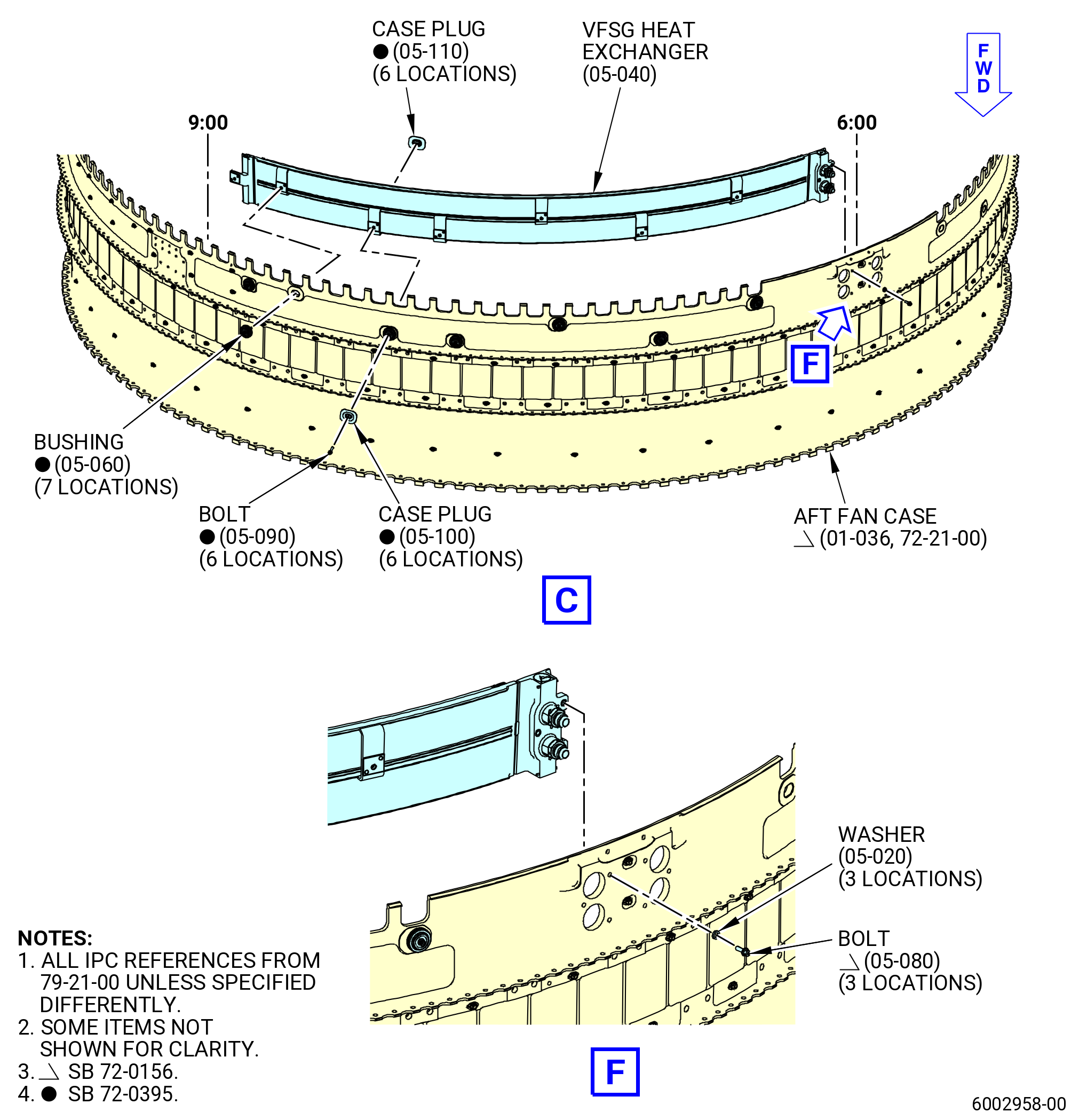
| (a).C. | Remove the nine bushings (05-060 , 79-21-00) (SIN 52191), the three machine bolts (bolts) (05-090 , 79-21-00) (SIN 5212E), the three case plugs (05-100 , 79-21-00) (SIN 52161), and the three case plugs (05-110 , 79-21-00) (SIN 52162), that attach the engine heat exchanger (05-010 , 79-21-00) (SIN 52102) to the aft fan case (01-035 , 72-21-00) (SIN 84100) or (01-036 , 72-21-00) (SIN 84100). |
| * * * END SB 72-0395 |
| Subtask 72-00-01-040-091 |
| (b) | Remove the four machine bolts (bolts) (05-050 , 79-21-00) (SIN 52126) and flat washers (washers) (05-020 , 79-21-00) (SIN 52138) that connect the engine heat exchanger to the fan case oil heat exchanger port at the 3:00 o'clock position. |
| (c) | Push the engine heat exchanger at the 3:00 o'clock position to release it from the aft fan case. |
| (d) | Remove the engine heat exchanger from the aft fan case at the 12:00 thru 3:00 o'clock position. |
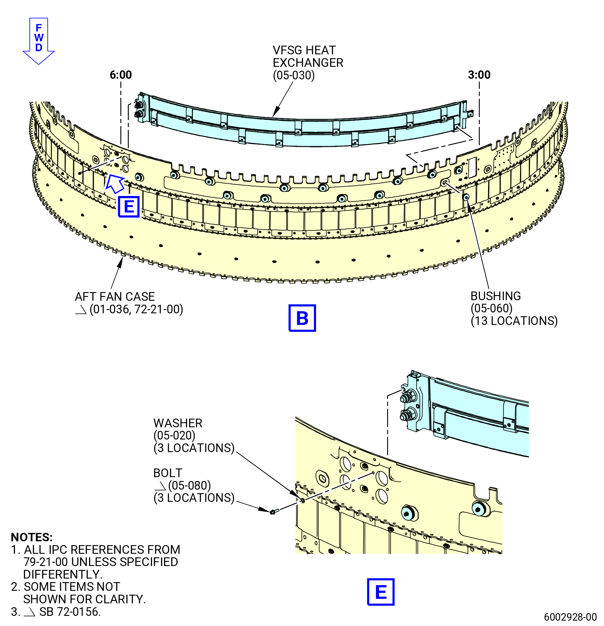
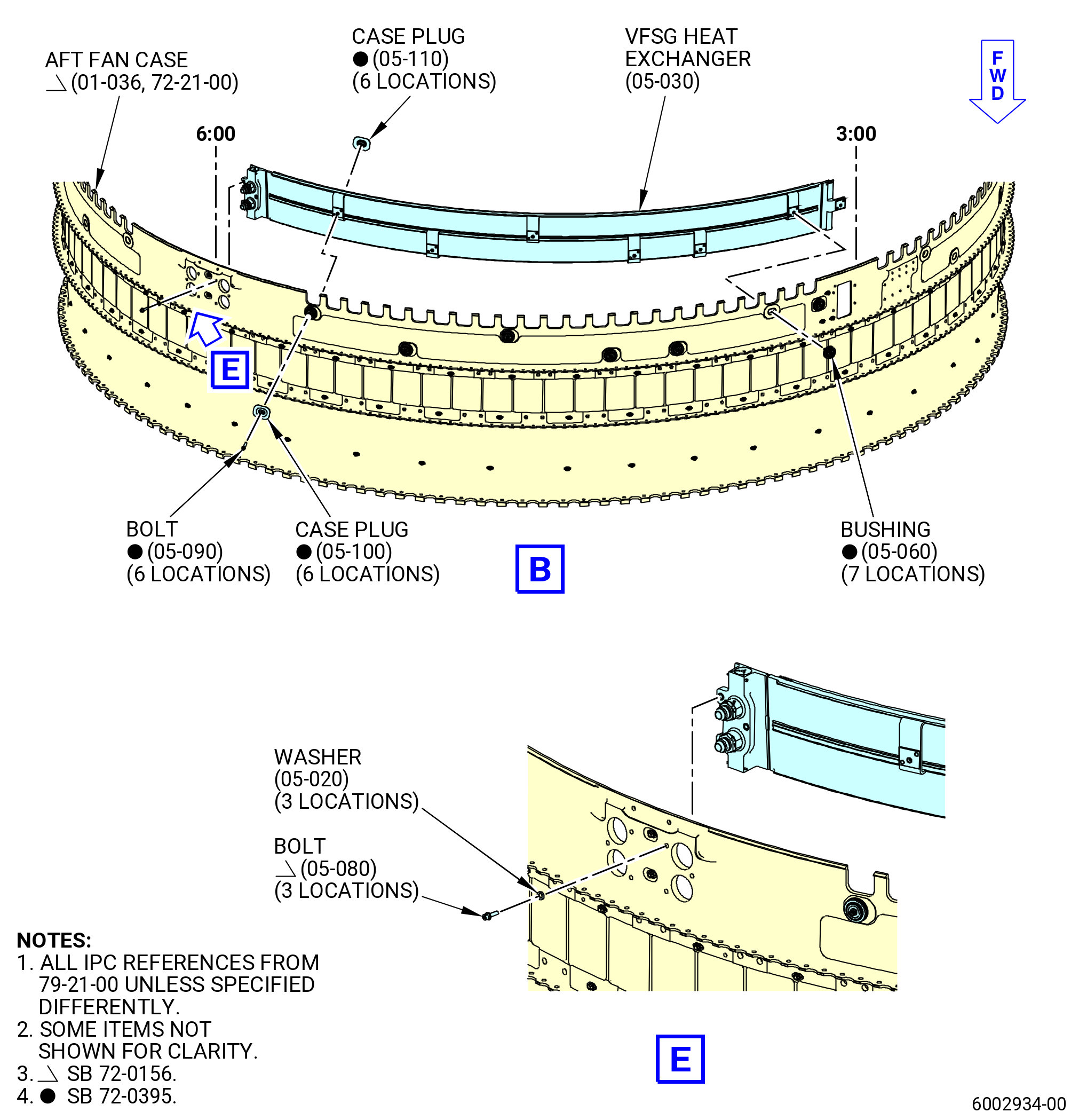
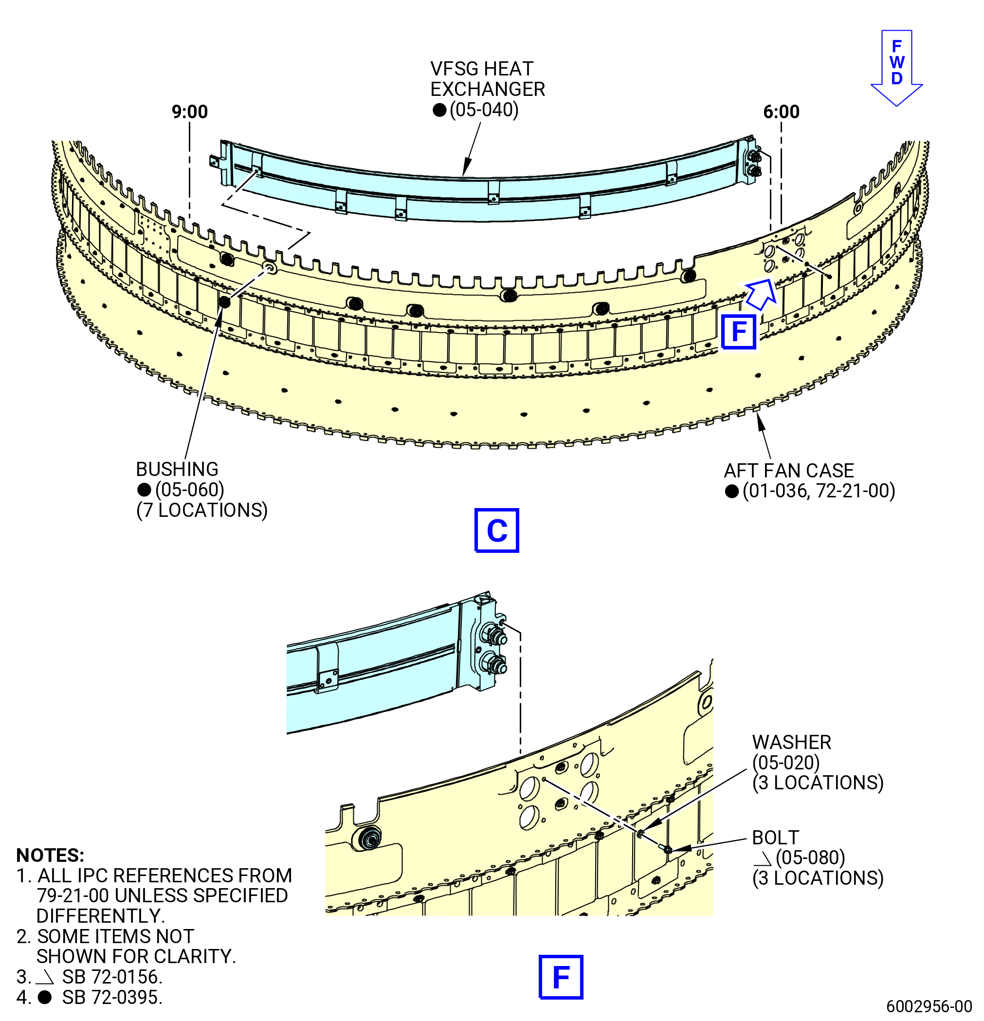
| (30) | Remove the VFSG heat exchanger (05-030 , 79-21-00) (SIN 52101) as follows: |
| Subtask 72-00-01-040-092 |
| * * * FOR 1B/P/G03.1B/P/G04.1B/P1/G01 |
| * * * PRE SB 72-0395( Old Surface Cooler System ) |
| (a) | Remove the 13 bushings (05-060 , 79-21-00) (SIN 52191) that attach the engine heat exchanger (05-030 , 79-21-00) (SIN 52101) to the aft fan case (01-035 , 72-21-00) (SIN 84100). |
| * * * END PRE SB 72-0395 |
| Subtask 72-00-01-040-093 |
| * * * FOR ALL PIP 2 |
| * * * PRE SB 72-0395( Old Surface Cooler System ) |
| * * * SB 72-0156( Fan Module PIP 2 Configuration ) |
| (a).A. | Remove the 13 bushings (05-060 , 79-21-00) (SIN 52191) that attach the engine heat exchanger (05-030 , 79-21-00) (SIN 52101) to the aft fan case (01-036 , 72-21-00) (SIN 84100). |
| * * * END PRE 72-0395 |
| * * * END SB 72-0156 |
| Subtask 72-00-01-040-094 |
| * * * FOR ALL PIP 2 |
| * * * SB 72-0395( Optimized Surface Cooler System - Production ) |
| (a).B. | Remove the seven bushings (05-060 , 79-21-00) (SIN 52191) that attach the engine heat exchanger (05-030 , 79-21-00) (SIN 52101) to the aft fan case (01-036 , 72-21-00) (SIN 84100). |
| * * * END SB 72-0395 |
| Subtask 72-00-01-040-095 |
| * * * FOR ALL |
| * * * SB 72-0395( Optimized Surface Cooler System - Field ) |
| (a).C. | Remove the seven bushings (05-060 , 79-21-00) (SIN 52191), the six machine bolts (bolts) (05-090 , 79-21-00) (SIN 5212E), the six case plugs (05-100 , 79-21-00) (SIN 52161), and the six case plugs (05-110 , 79-21-00) (SIN 52162), that attach the engine heat exchanger (05-030 , 79-21-00) (SIN 52101) to the aft fan case (01-035 , 72-21-00) (SIN 84100) or (01-036 , 72-21-00) (SIN 84100). |
| * * * END SB 72-0395 |
| Subtask 72-00-01-040-096 |
| (b) | Remove the three bolts (05-050 , 79-21-00) (SIN 52126) or (05-080 , 79-21-00) (SIN 5212D) and washers (05-020 , 79-21-00) (SIN 52138) that connect the VFSG heat exchanger to the fan case oil heat exchanger port at the 6:00 o'clock position. |
| (c) | Push the engine heat exchanger at the 6:00 o'clock position to release it from the aft fan case. |
| (d) | Remove the VFSG heat exchanger from the aft fan case at the 3:00 thru 6:00 o'clock position. |
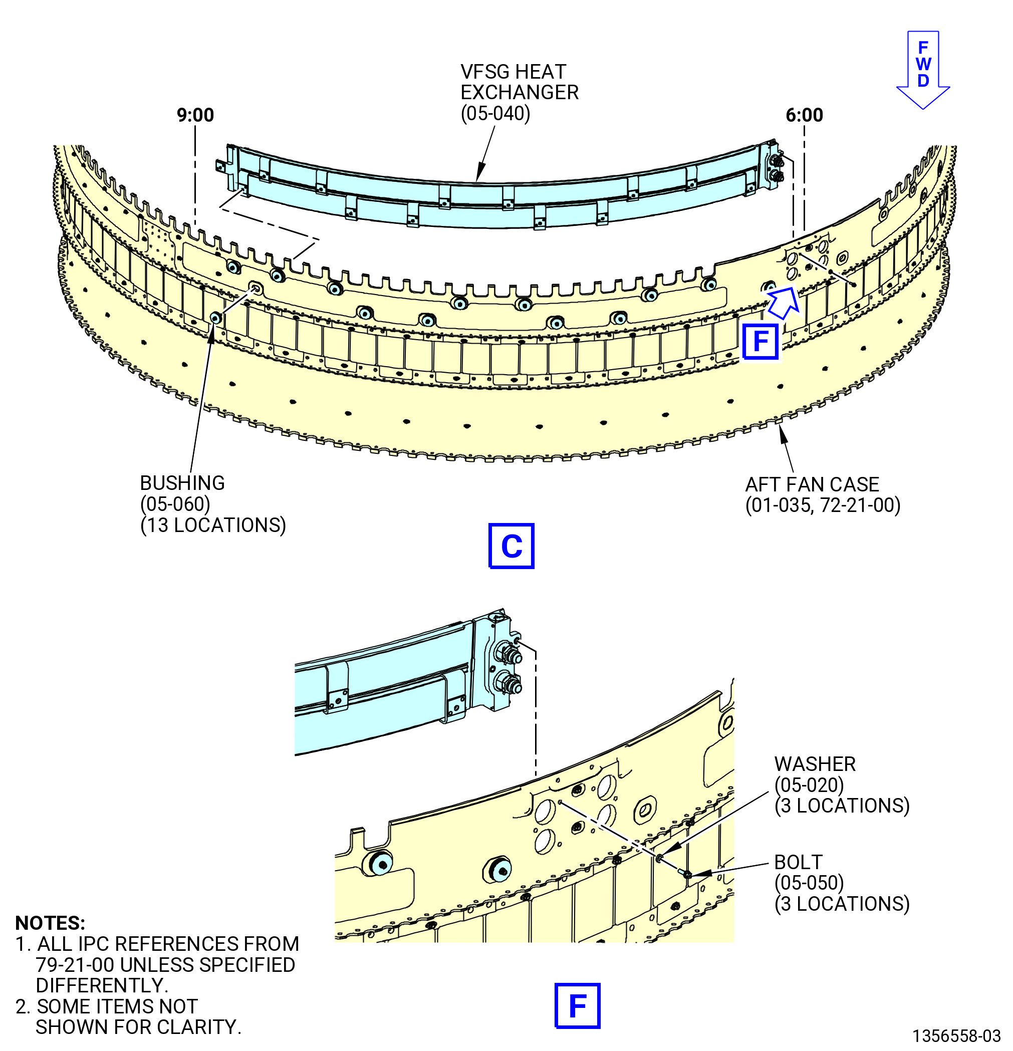
| (31) | Remove the VFSG heat exchanger (05-040 , 79-21-00) (SIN 52100) as follows: |
| Subtask 72-00-01-040-097 |
| * * * FOR 1B/P/G03.1B/P/G04.1B/P1/G01 |
| * * * PRE SB 72-0395( Old Surface Cooler System ) |
| (a) | Remove the 13 bushings (05-060 , 79-21-00) (SIN 52191) that attach the engine heat exchanger (05-040 , 79-21-00) (SIN 52100) to the aft fan case (01-035 , 72-21-00) (SIN 84100). |
| * * * END PRE SB 72-0395 |
| Subtask 72-00-01-040-098 |
| * * * FOR ALL PIP 2 |
| * * * PRE SB 72-0395( Old Surface Cooler System ) |
| * * * SB 72-0156( Fan Module PIP 2 Configuration ) |
| (a).A. | Remove the 13 bushings (05-060 , 79-21-00) (SIN 52191) that attach the engine heat exchanger (05-040 , 79-21-00) (SIN 52100) to the aft fan case (01-036 , 72-21-00) (SIN 84100). |
| * * * END PRE SB 72-0395 |
| * * * END SB 72-0156 |
| Subtask 72-00-01-040-099 |
| * * * FOR ALL PIP 2 |
| * * * SB 72-0395( Optimized Surface Cooler System - Production ) |
| (a).B. | Remove the seven bushings (05-060 , 79-21-00) (SIN 52191) that attach the engine heat exchanger (05-040 , 79-21-00) (SIN 52100) to the aft fan case (01-036 , 72-21-00) (SIN 84100). |
| * * * END SB 72-0395 |
| Subtask 72-00-01-040-100 |
| * * * FOR ALL |
| * * * SB 72-0395( Optimized Surface Cooler System - Field ) |
| (a).C. | Remove the seven bushings (05-060 , 79-21-00) (SIN 52191), the six machine bolts (bolts) (05-090 , 79-21-00) (SIN 5212E), the six case plugs (05-100 , 79-21-00) (SIN 52161), and the six case plugs (05-110 , 79-21-00) (SIN 52162), that attach the engine heat exchanger (05-040 , 79-21-00) (SIN 52100) to the aft fan case (01-035 , 72-21-00) (SIN 84100) or (01-036 , 72-21-00) (SIN 84100). |
| * * * END SB 72-0395 |
| Subtask 72-00-01-040-101 |
| (b) | Remove the three bolts (05-050 , 79-21-00) (SIN 52126) or (05-080 , 79-21-00) (SIN 5212D) and washers (05-020 , 79-21-00) (SIN 52138) that connect the VFSG heat exchanger to the fan case oil heat exchanger port at the 6:00 o'clock position. |
| (c) | Push the engine heat exchanger at the 6:00 o'clock position to release it from the aft fan case. |
| (d) | Remove the VFSG heat exchanger from the aft fan case at the 6:00 thru 9:00 o'clock position. |
|
|
|
|
|
|
|
|
|
| Subtask 72-00-01-040-056 |
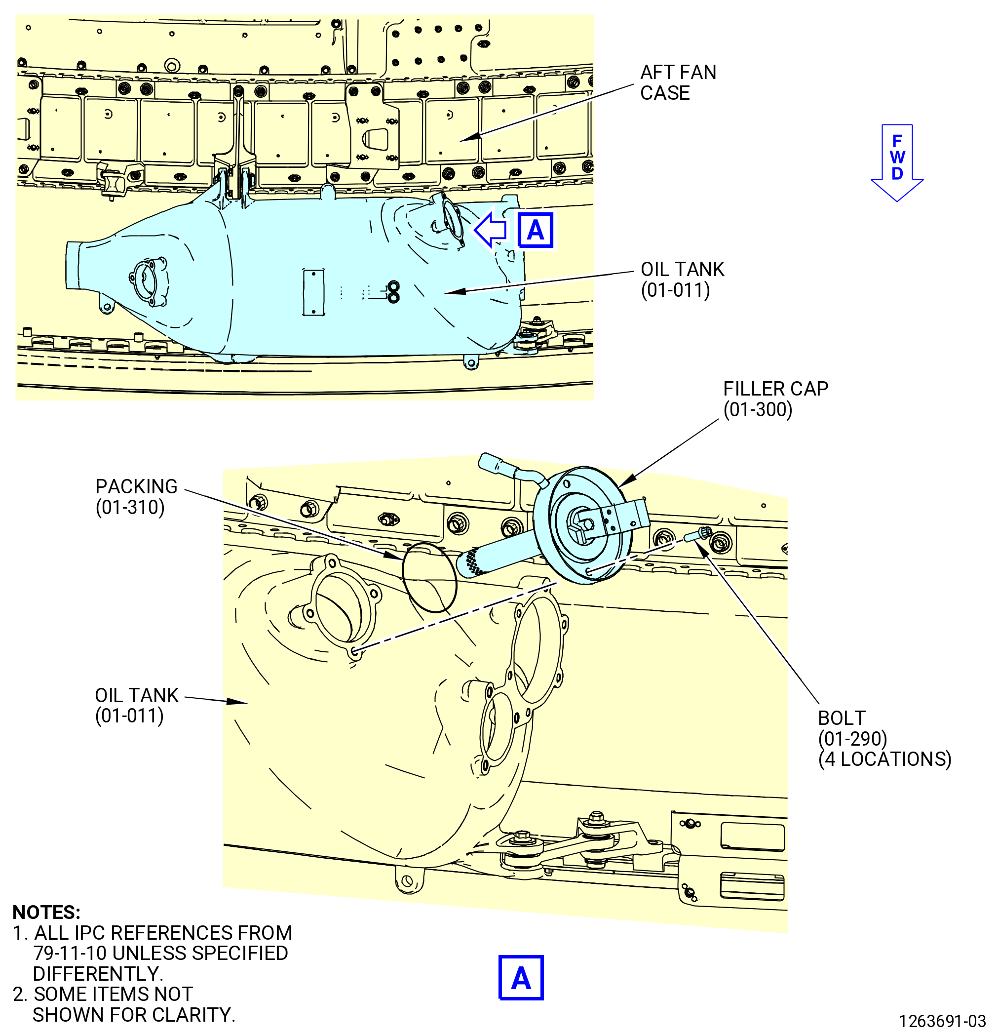
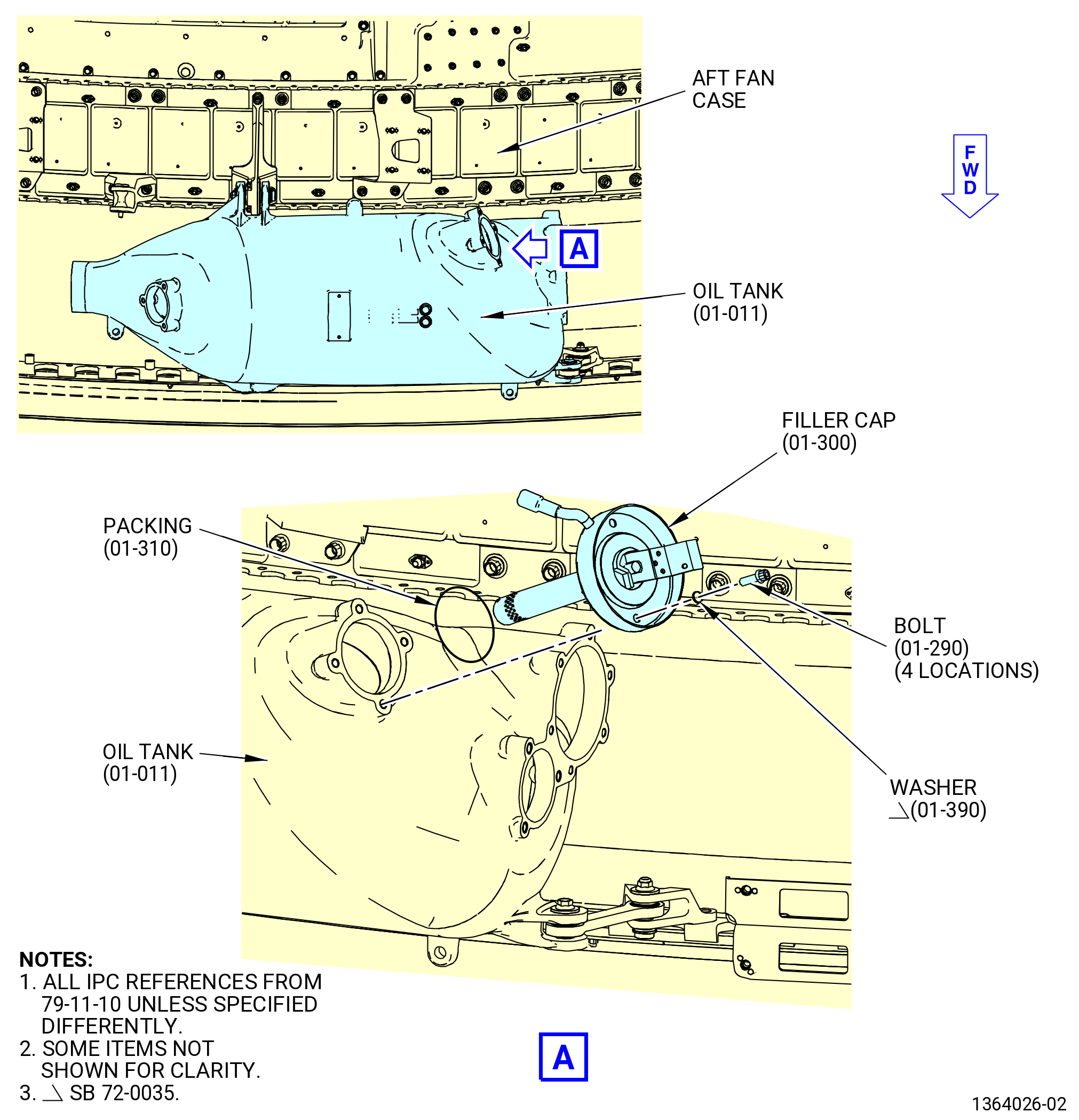
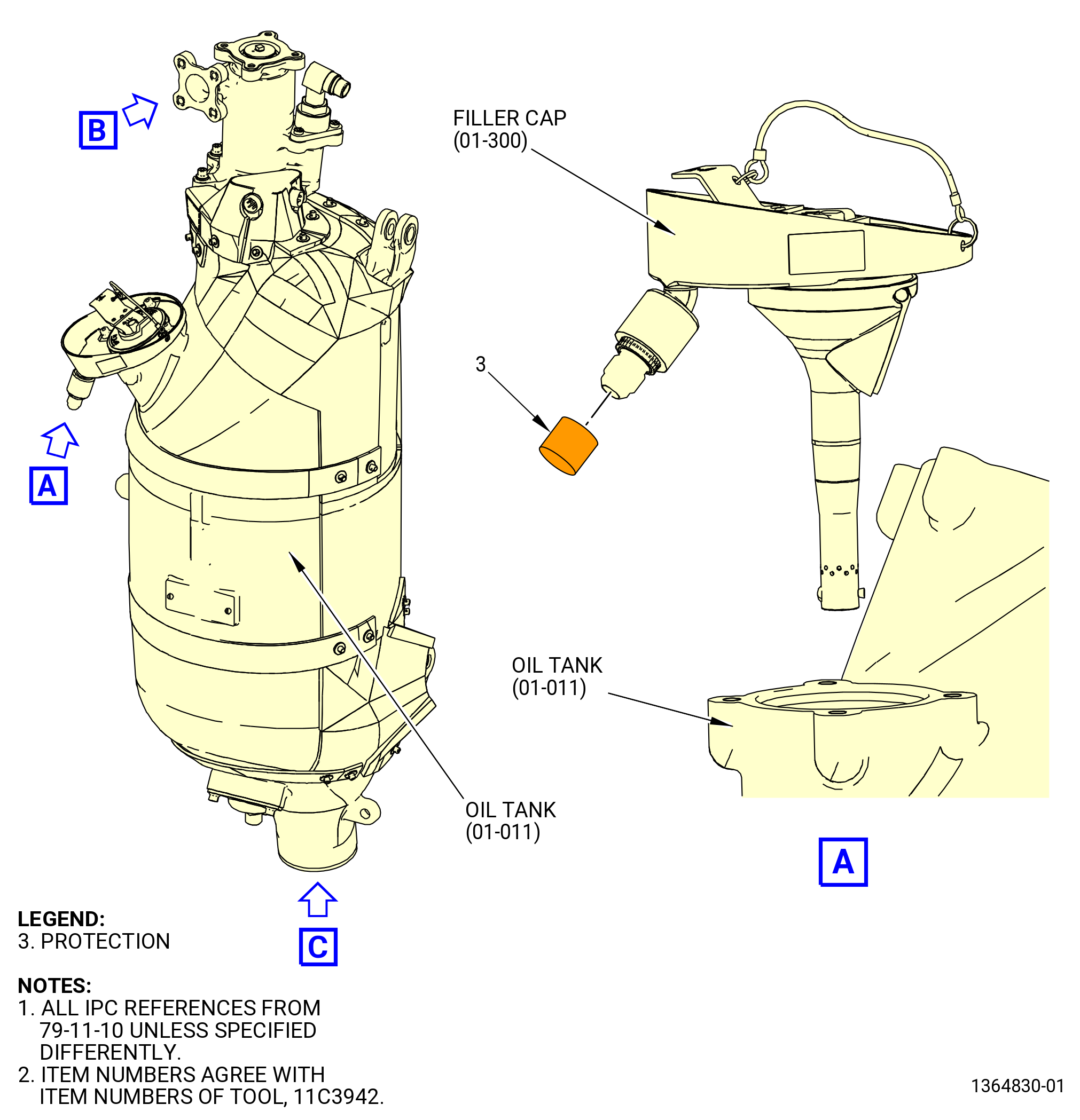
| F. | Remove the filler cap (01-300 , 79-11-10) (SIN 400A4) from the oil tank (01-011 , 79-11-10) (SIN 40000) as follows. Refer to Figure 511. |
| (1) | Remove the oil tank heat shield from around the oil tank. |
| (2) | Remove the machine bolts (bolts) (01-290 , 79-11-10) (SIN 40320) at four locations from the filler cap. |
| Subtask 72-00-01-040-070 |
| * * * SB 72-0035( Filler Cap Bolts with Washers ) |
| (3) | Remove the four flat washers (washers)(01-390 , 79-11-10) (SIN 40037) from the filler cap (01-300 , 79-11-10) (SIN 400A4). Refer to Figure 511A. |
| NOTE: |
|
| * * * END SB 72-0035 |
| Subtask 72-00-01-040-071 |
| CAUTION: |
|
| (4) | Remove the filler cap (01-300 , 79-11-10) (SIN 400A4) from the oil tank (01-011 , 79-11-10) (SIN 40000). |
| (5) | Remove and discard the preformed packing (packing) (01-310 , 79-11-10) (SIN 40350) from the filler cap. |
| Subtask 72-00-01-040-057 |
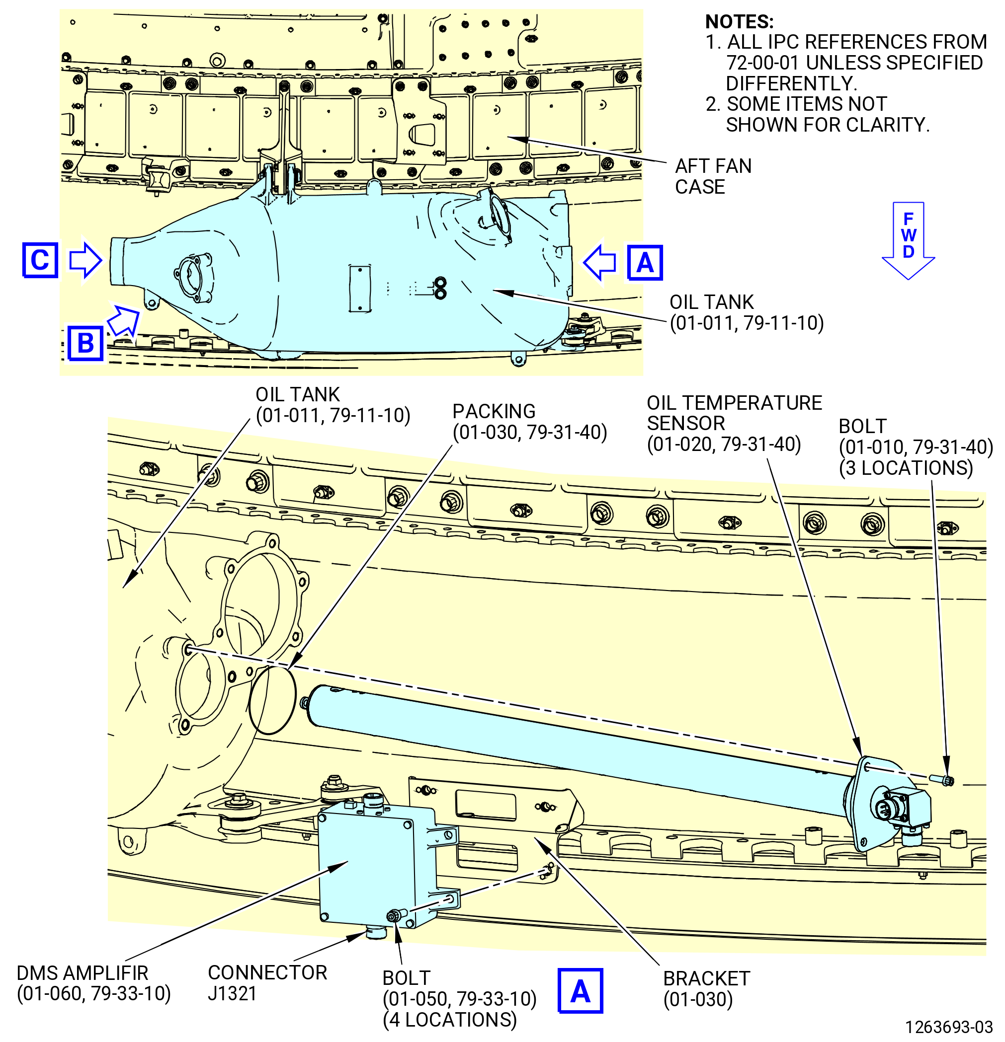
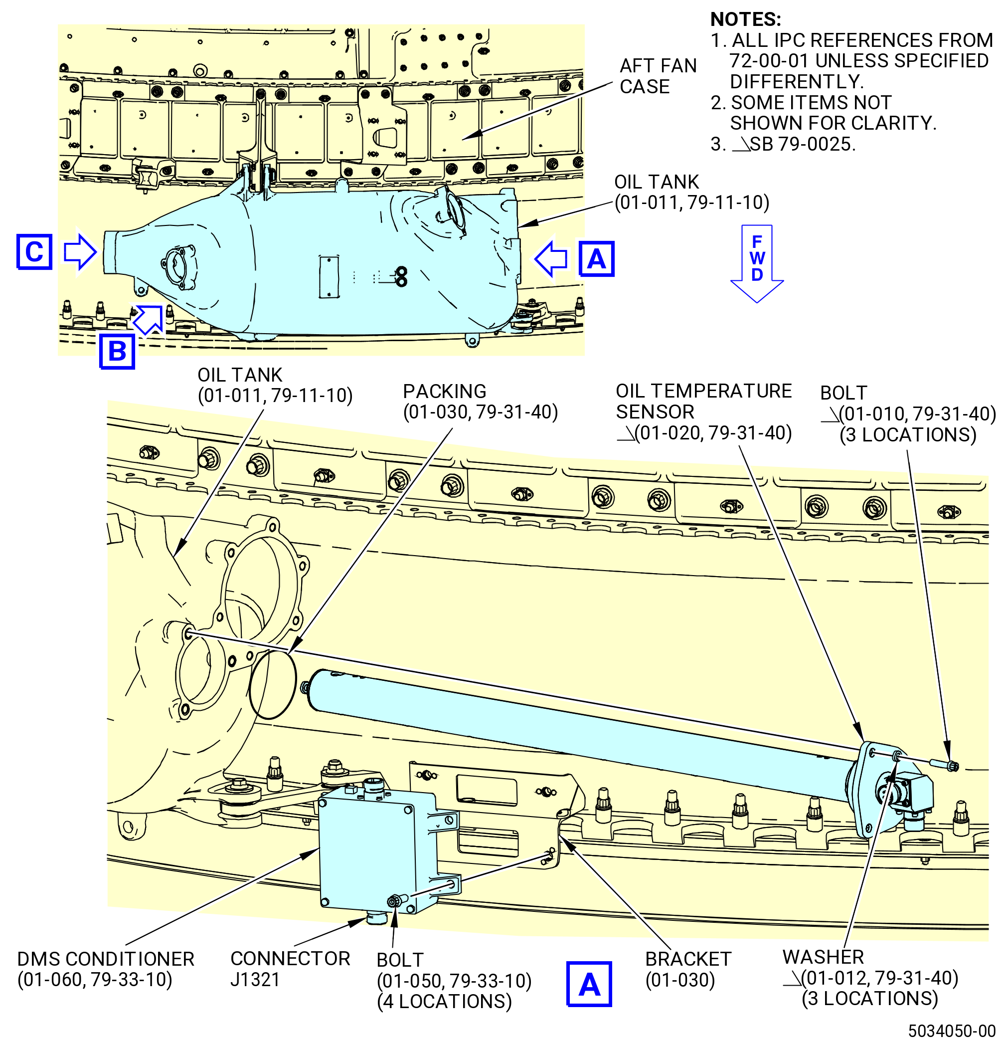
| G. | Remove the oil temperature sensor (01-020 , 79-31-40) (SIN 400A3) from the oil tank (01-011 , 79-11-10) (SIN 40000) as follows. Refer to Figure 512. |
| Subtask 72-00-01-040-073 |
| * * * PRE SB 79-0025( Removal of Oil Temperature Sensor without Washers Attached ) |
| (1) | Remove the machine bolts (bolts) (01-010 , 79-31-40) (SIN 4002C) at three locations from the oil temperature sensor. |
| * * * END PRE SB 79-0025 |
| Subtask 72-00-01-040-074 |
| * * * SB 79-0025( Removal of Oil Temperature Sensor with Washers Attached ) |
| (1).A. | Remove the bolts (01-010 , 79-31-40) (SIN 4002C) and flat washers (washers) (01-012 , 79-31-40) (SIN 40039) at three locations from the oil temperature sensor. |
| * * * END SB 79-0025 |
| Subtask 72-00-01-040-075 |
| (2) | Remove the oil temperature sensor from the oil tank. |
| (3) | Remove and discard the preformed packing (packing) (01-030 , 79-31-40) (SIN 40052) from the oil temperature sensor. |
| Subtask 72-00-01-040-058 |
| H. | Remove the DMS amplifir (01-060 , 79-33-10) (SIN 42500) from the bracket (01-030) (SIN 42510) on the fan stator case as follows. Refer to Figure 512. |
| (1) | Remove the bolts (01-050 , 79-33-10) (SIN 42521) at four locations from the bracket on the fan stator case. |
| (2) | Remove the DMS conditioner from the bracket. |
| Subtask 72-00-01-040-059 |
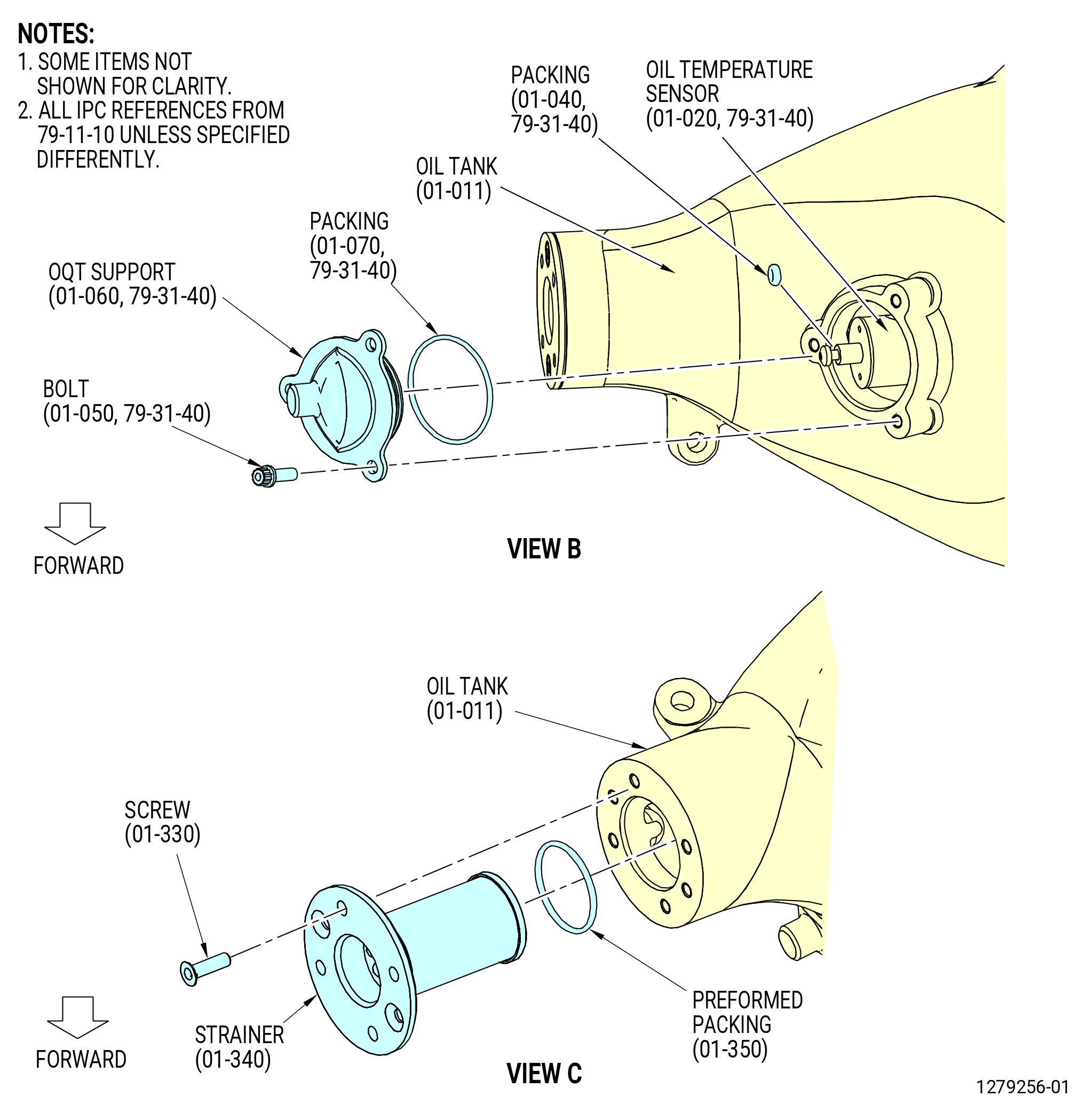
| I. | Remove the oil temperature support (OQT support) (01-060 , 79-31-40) (SIN 40001) and the strainer (01-340 , 79-11-10) (SIN 400A0) from the oil tank (01-011 , 79-11-10) (SIN 40000) as follows. Refer to Figure 512. |
| CAUTION: |
|
| (1) | With the oil temperature sensor (01-020 , 79-31-40) (SIN 400A3) not installed, remove the OQT support as follows: |
| (a) | Remove the machine bolts (bolts) (01-050 , 79-31-40) (SIN 4002D) at three locations from the OQT support. |
| (b) | Remove the OQT support from the oil tank. |
| (c) | Remove and discard the preformed packing (packing) (01-070 , 79-31-40) (SIN 40054) from the OQT support. |
| (d) | Remove and discard the preformed packing (packing) (01-040 , 79-31-40) (SIN 40053) from the oil temperature sensor (01-020 , 79-31-40) (SIN 400A3). |
| (2) | Remove the strainer as follows: |
| (a) | Remove the screws (01-330 , 79-11-10) (SIN 40029) at two locations from the strainer (01-340 , 79-11-10) (SIN 400A0). |
| (b) | Remove the strainer (01-340 , 79-11-10) (SIN 400A0) from the oil tank. |
| (c) | Remove and discard the preformed packing (01-350 , 79-11-10) (SIN 40050) from the strainer. |
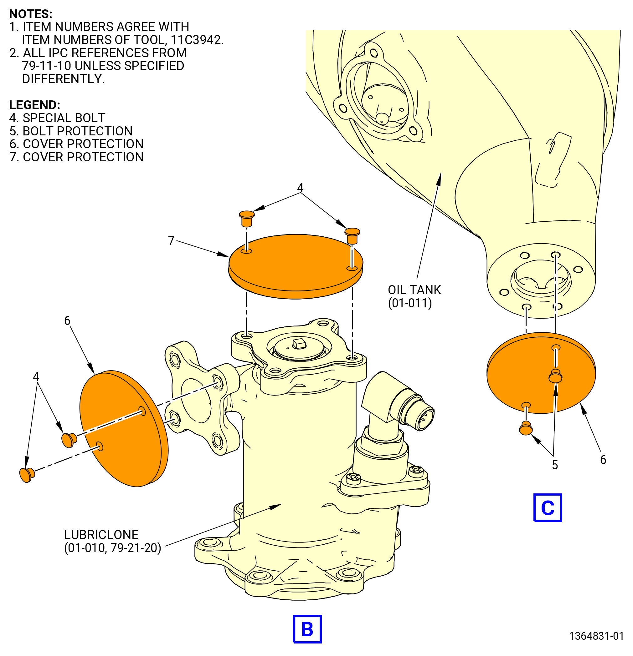
| (d) | Install the 11C3942 protection tool set as follows. Refer to Figure 513. |
| 1 | Install the protection (item 3) to the oil filler cap (01-300 , 79-11-10) (SIN 400A4). |
| 2 | Attach the cover protection (item 6) to the side of the lubriclone (01-010 , 79-21-20) (SIN 400A1) with two special bolts (item 4). |
| 3 | Attach the cover protection (item 7) to the upper side of the lubriclone with two special bolts (item 4). |
| 4 | Attach the cover protection (item 6) to the oil tank with two bolt protections (item 5). |
| Subtask 72-00-01-040-060 |
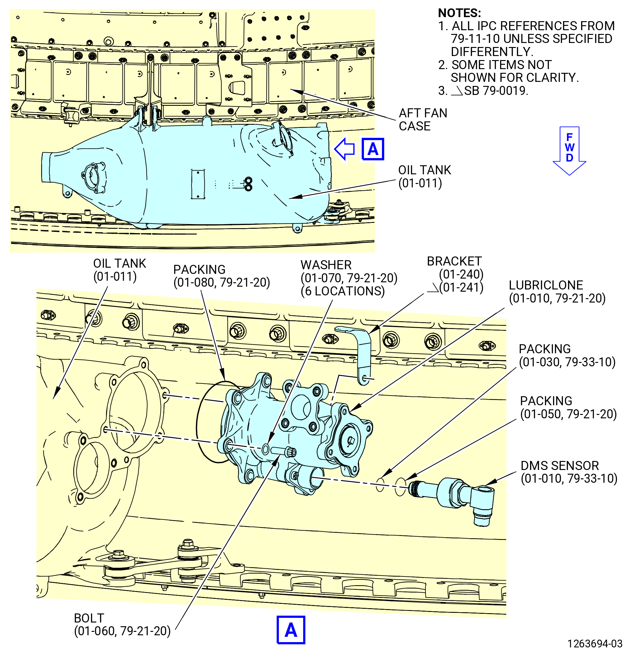
| J. | Remove the DMS sensor (01-010 , 79-33-10) (SIN 42100) from the lubriclone (01-010 , 79-21-20) (SIN 400A1) on the oil tank (01-011 , 79-11-10) (SIN 40000) as follows. Refer to Figure 514. |
| (1) | Loosen the B-nut on the DMS sensor. |
| (2) | Remove the DMS sensor from the lubriclone. |
| (3) | Remove and discard the preformed packings (packings) (01-050A , 79-21-20) (SIN 40055) and (01-030 , 79-33-10) (SIN 42150) at two locations. |
|
|
|
|
| Subtask 72-00-01-040-061 |
| K. | Remove the lubriclone (01-010 , 79-21-20) (SIN 400A1) from the oil tank (01-011 , 79-11-10) (SIN 40000) as follows. Refer to Figure 514. |
| (1) | Remove the bolts (01-060 , 79-21-20) (SIN 4002A) and flat washers (washers) (01-070 , 79-21-20) (SIN 40035), at six locations, and the bonding strap (bracket) (01-240 , 79-11-10) (SIN 40110) or (01-241 , 79-11-10) (SIN 40110) from the lubriclone. |
| (2) | Remove the lubriclone from the oil tank. |
| (3) | Remove and discard the preformed packing (packing) (01-080 , 79-21-20) (SIN 40051) from the lubriclone. |
| Subtask 72-00-01-040-062 |
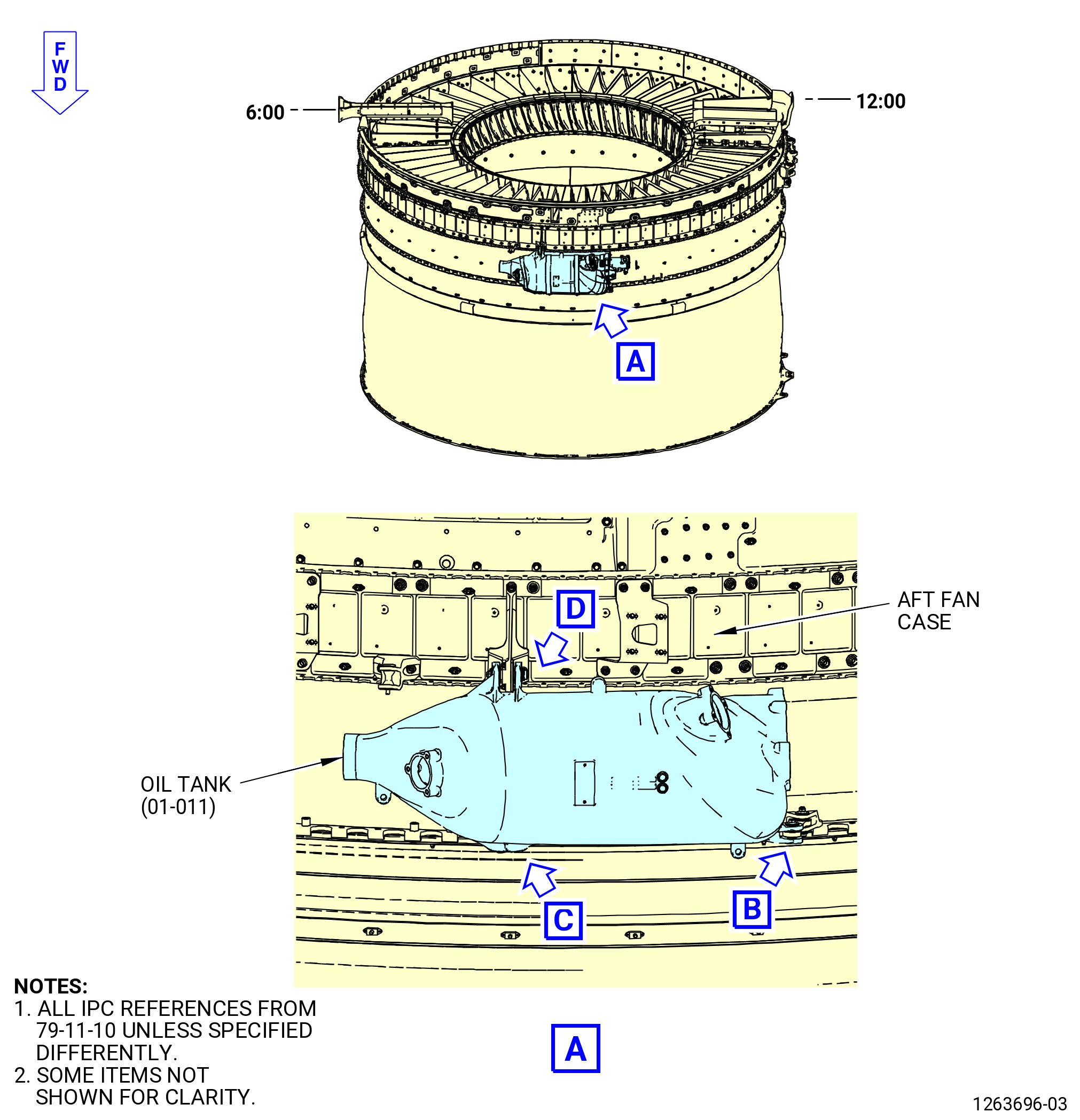
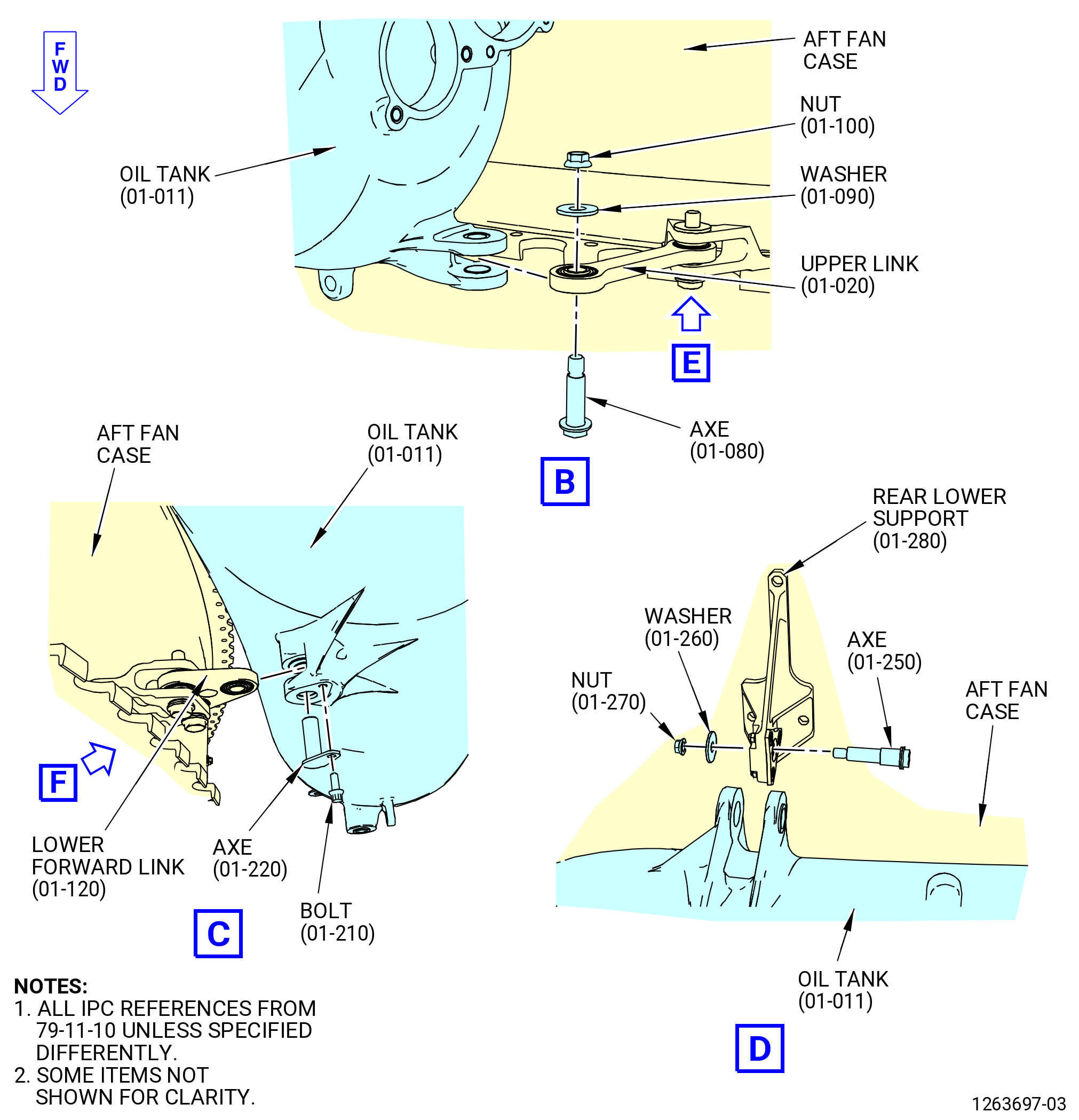
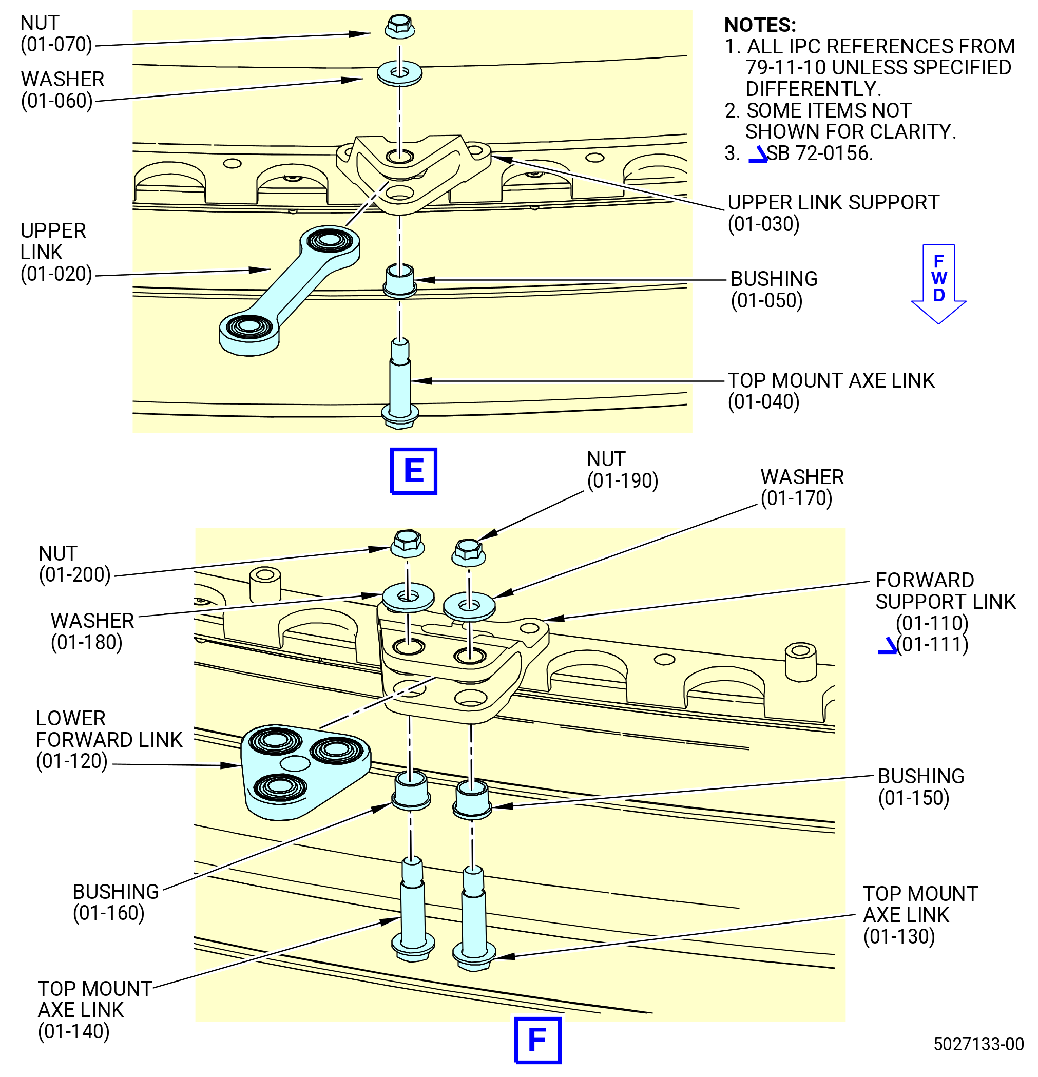
| L. | Remove the oil tank (01-011 , 79-11-10) (SIN 40000) and support brackets (10-100) (SIN 46012) from the aft fan case. Refer to Figure 515 and do as follows: |
| (1) | Remove the bolt (01-210 , 79-11-10) (SIN 4002B) that attach the axe (01-220 , 79-11-10) (SIN 40024) to the lower forward link (01-120 , 79-11-10) (SIN 40011). |
| (2) | Remove the self-locking nut (nut) (01-270 , 79-11-10) (SIN 40043) and washer (01-260 , 79-11-10) (SIN 40030) from the axe (01-250 , 79-11-10) (SIN 40020) on the rear lower support (01-280 , 79-11-10) (SIN 40010). |
| (3) | Remove the axe (01-250 , 79-11-10) (SIN 40020) from the rear lower support. |
| (4) | Remove the self-locking nut (nut) (01-100 , 79-11-10) (SIN 40042) and washer (01-090 , 79-11-10) (SIN 40032) from the axe (01-080 , 79-11-10) (SIN 40027) on the upper link (01-020 , 79-11-10) (SIN 40013). |
| (5) | Hold the oil tank tight and remove the axe (01-080 , 79-11-10) (SIN 40027) from the upper link. |
| (6) | Remove the oil tank from the aft fan case and put it in a storage area or install it on the 2129M54 assembly stand. |
| (7) | Remove the upper link from the upper link support (01-030 , 79-11-10) (SIN 40014) as follows: |
| (a) | Remove the self-locking nut (nut) (01-070 , 79-11-10) (SIN 40040) and washer (01-060 , 79-11-10) (SIN 40031) from the top mount axe link (01-040 , 79-11-10) (SIN 40022). |
| (b) | Remove the top mount axe link (01-040 , 79-11-10) (SIN 40022) and bushing (01-050 , 79-11-10) (SIN 40070) from the upper link support. |
| (c) | Remove the upper link from the upper link support. |
| (8) | Remove the lower forward link from the forward support link (01-110 , 79-11-10) (SIN 40012) or (01-111 , 79-11-10) (SIN 40012) as follows: |
| (a) | Remove the self-locking nuts (nuts) (01-190 , 79-11-10) (SIN 40045) and (01-200 , 79-11-10) (SIN 40044) and washer (01-170 , 79-11-10) (SIN 40034) and (01-180 , 79-11-10) (SIN 40033) from the top mount axe links (01-130 , 79-11-10) (SIN 40026) and (01-140 , 79-11-10) (SIN 40023) at two locations. |
| (b) | Remove the top mount axe links (01-130 , 79-11-10) (SIN 40026) and (01-140 , 79-11-10) (SIN 40023) and the bushing (01-150 , 79-11-10) (SIN 40072) and (01-160 , 79-11-10) (SIN 40071) from the forward link support. |
| (c) | Remove the lower forward link from the forward support link. |
| Subtask 72-00-01-040-063 |
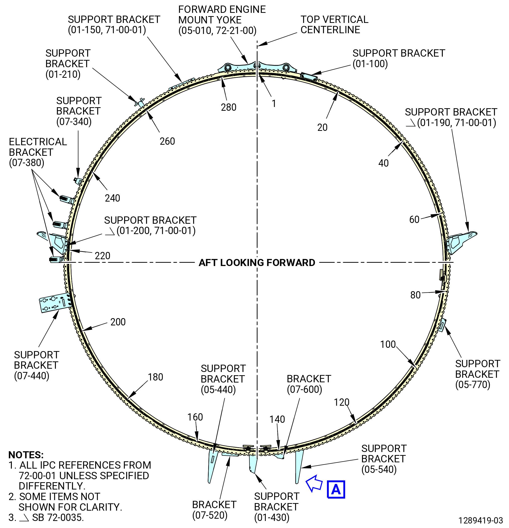
| M. | Remove the brackets from the fan case assembly aft ring flange as follows. Refer to Figure 516. |
| (1) | Remove the nuts, washers, and bolts that attach the brackets to the aft ring flange. |
| (2) | Remove the brackets as follows: |
| (a) | Remove the oil tube support bracket (support bracket) (01-100) (SIN 46011) from boltholes No. 9 and 12. |
| (b) | Remove the support bracket (01-190 , 71-00-01) (SIN 99111) from boltholes No. 65 thru 67 and from PDOS bracket (25-010 , 71-00-00) (SIN 95111). |
| (c) | Remove the machine bolts (bolts) (05-820) (SIN 4482B) that attach the support bracket (05-770) (SIN 44815) to the support bracket (05-790) (SIN 44816). |
| (d) | Remove the support bracket (05-770) (SIN 44815) from boltholes No. 84 thru 86. |
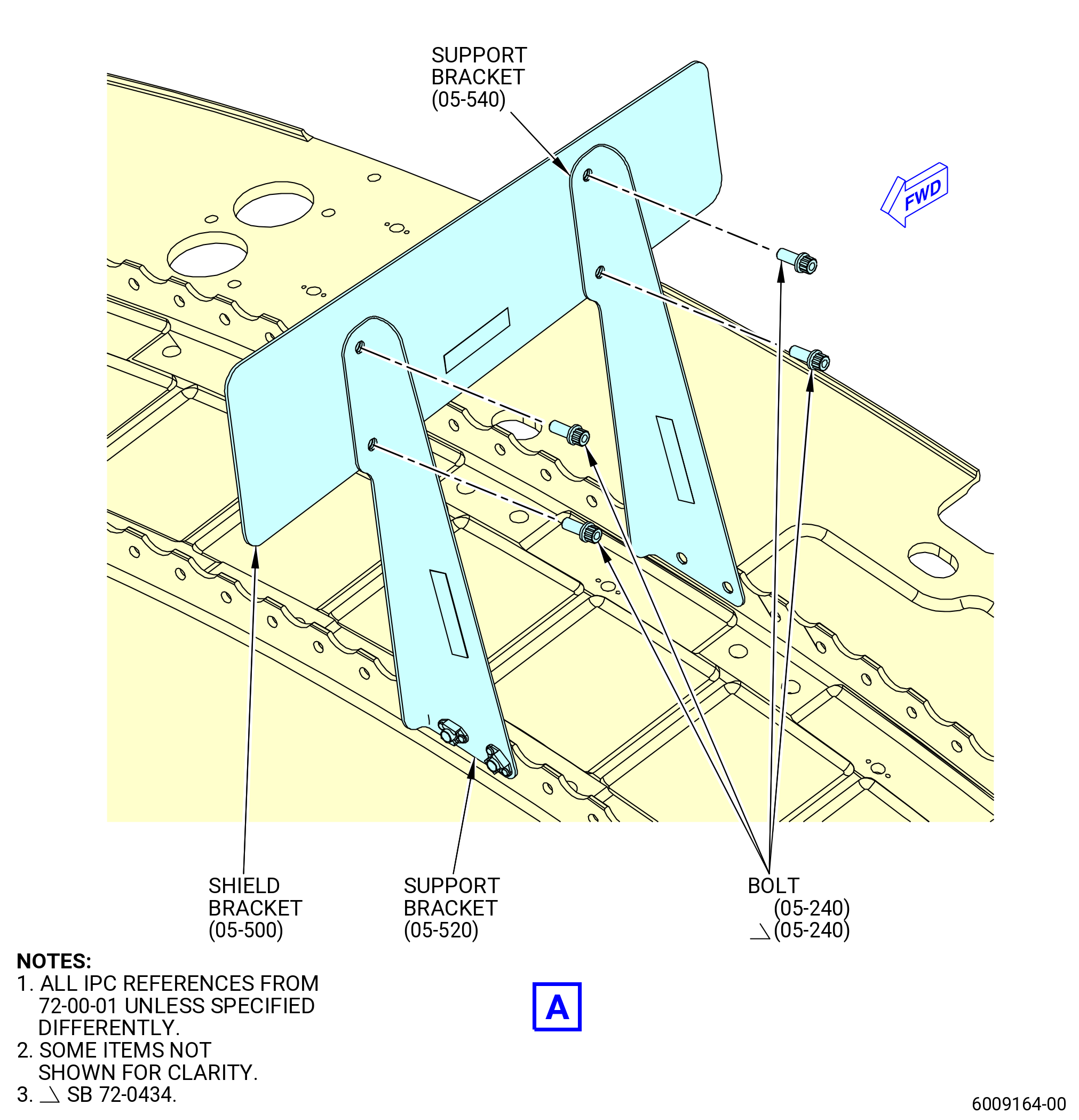
| (e) | Remove the two machine bolts (bolts) (05-240) (SIN 67021) that attach the shield bracket (05-500) (SIN 6701G) to the support bracket (05-540) (SIN 67014). |
| (f) | Remove the two bolts (05-240) (SIN 67021) that attach the shield bracket (05-500) (SIN 6701G) to the support bracket (05-520) (SIN 6701J). |
| (g) | Remove the support bracket (05-540) (SIN 67014) from boltholes No. 131 and 132. |
| (h) | Remove the bracket (07-600) (SIN 5211F) from boltholes No. 137 and 138. |
| (i) | Remove the PS3 aft support tube bracket (support bracket) (01-430) (SIN 61417) from boltholes No. 142 and 143. |
| (j) | Remove the bracket (07-520) (SIN 5211Y) from boltholes No. 147 thru 150. |
| (k) | Remove the support bracket (05-440) (SIN 6701K) from shield bracket (05-400) (SIN 6701F) or (05-401) (SIN 6701F) and from boltholes No. 152 and 153. |
| (l) | Remove the support bracket (bracket) (07-440) (SIN 6701L) from boltholes No. 204 thru 206. |
| (m) | Remove the electrical brackets (bracket) (07-380) (SIN 61310) from boltholes No. 214 and 215, 221 and 222, and 228 and 229. |
| (n) | Remove the support bracket (01-200 , 71-00-01) (SIN 99112) from boltholes No. 217 thru 219 and from PDOS bracket (25-020 , 71-00-00) (SIN 95112). |
| (o) | Remove the support bracket (bracket) (07-340) (SIN 6701A) from boltholes No. 233 and 234. |
| (p) | Remove the DLODS support bracket (support bracket) (01-210) (SIN 9801H) from bolthole No. 257. |
| (q) | Remove the support bracket (01-150 , 71-00-01) (SIN 6101Z) from boltholes No. 267 thru 269. |
| Subtask 72-00-01-040-064 |
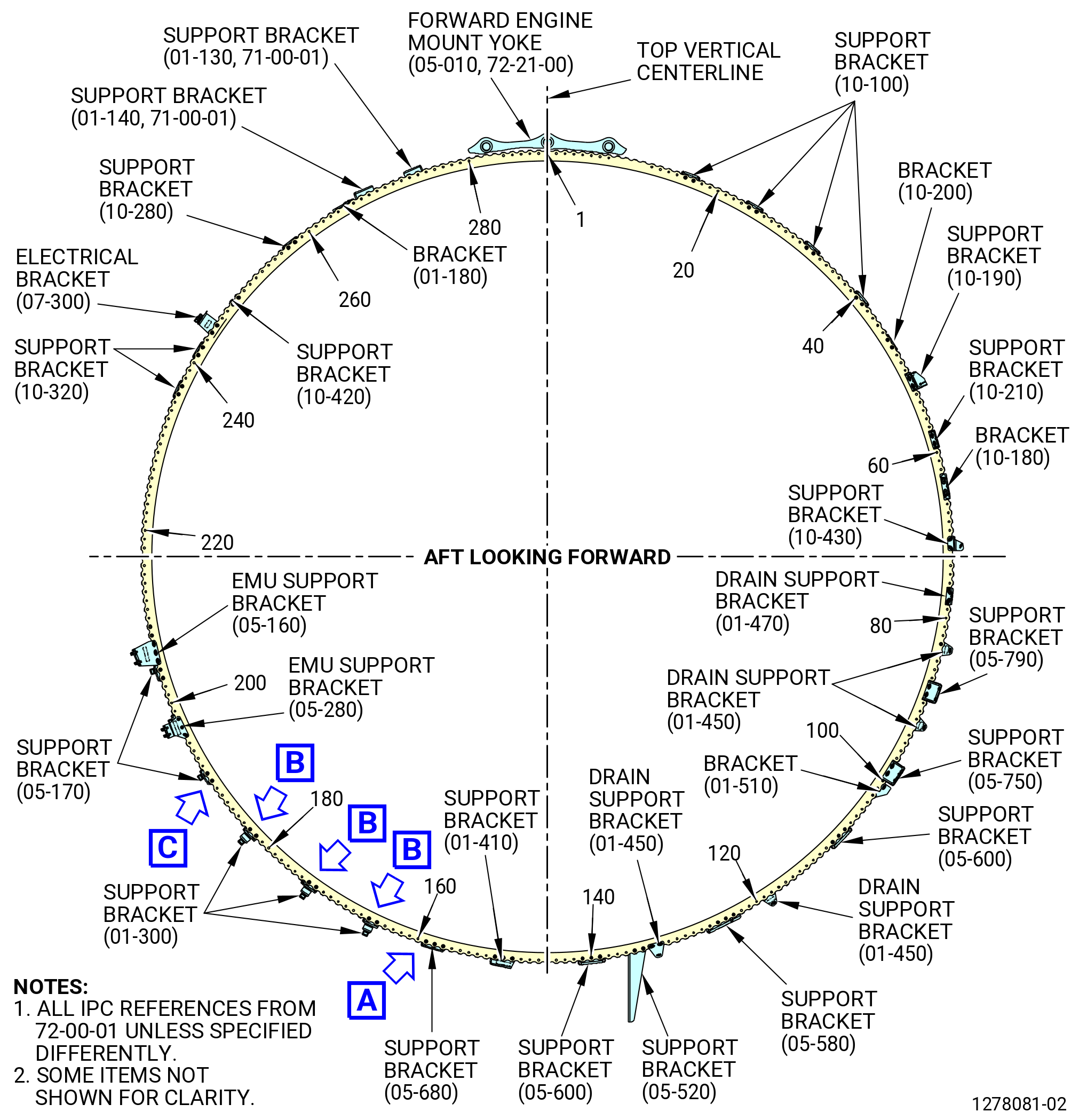
| N. | Remove the brackets from the aft fan case mid ring as follows. Refer to Figure 517. |
| (1) | Remove the nuts, bolts, and spacers that connect the brackets to the fan case forward ring flange. Remove the brackets as follows: |
| (a) | Remove the machine bolts (bolts) (10-160) (SIN 46025) that attach the support brackets (10-100) (SIN 46012) to the support brackets (10-130) (SIN 46013). |
| NOTE: |
|
| (b) | Remove the support brackets (10-100) (SIN 46012) from boltholes No. 13 and 14, 21 and 22, 29 and 30, and 37 and 38. |
| (c) | Remove the bracket (10-200) (SIN 53318) from boltholes No. 43 and 44. |
| (d) | Remove the right PDOS support bracket (support bracket) (10-190) (SIN 53314) from boltholes No. 48 and 49. |
| (e) | Remove the support bracket (10-210) (SIN 5331A) from boltholes No. 55 and 56. |
| (f) | Remove the bracket (10-180) (SIN 53313) from boltholes No. 60 and 62. |
| (g) | Remove the support bracket (10-430) (SIN 5331B) from boltholes No. 67 and 68. |
| (h) | Remove the drain support bracket (01-470) (SIN 48511) from boltholes No. 73 and 74. |
| (i) | Remove the drain support brackets (01-450) (SIN 48510) from boltholes No. 79 and 80, No. 88 and 89, No. 114 and 115, and No. 128 and 129. |
| (j) | Remove the support bracket (05-790) (SIN 44816) from boltholes No. 84 and 85. |
| (k) | Remove the support bracket (05-750) (SIN 44814) from boltholes No. 94 and 95. |
| (l) | Remove the bracket (01-510) (SIN 48512) from boltholes No. 97 and 98. |
| (m) | Remove the support bracket (05-600) (SIN 44011) from bolthole No. 103 thru 105, and No. 135 thru 137. |
| (n) | Remove the support bracket (05-580) (SIN 44010) from boltholes No. 120 thru 122. |
| (o) | Remove the support bracket (05-520) (SIN 6701J) from boltholes No. 130 and 131. |
| (p) | Remove the PS3 tube and support bracket (support bracket) (01-410) (SIN 61418) from boltholes No. 145 thru 147. |
| (q) | Remove the support bracket (05-680) (SIN 61412) from boltholes No. 153 thru 155. |
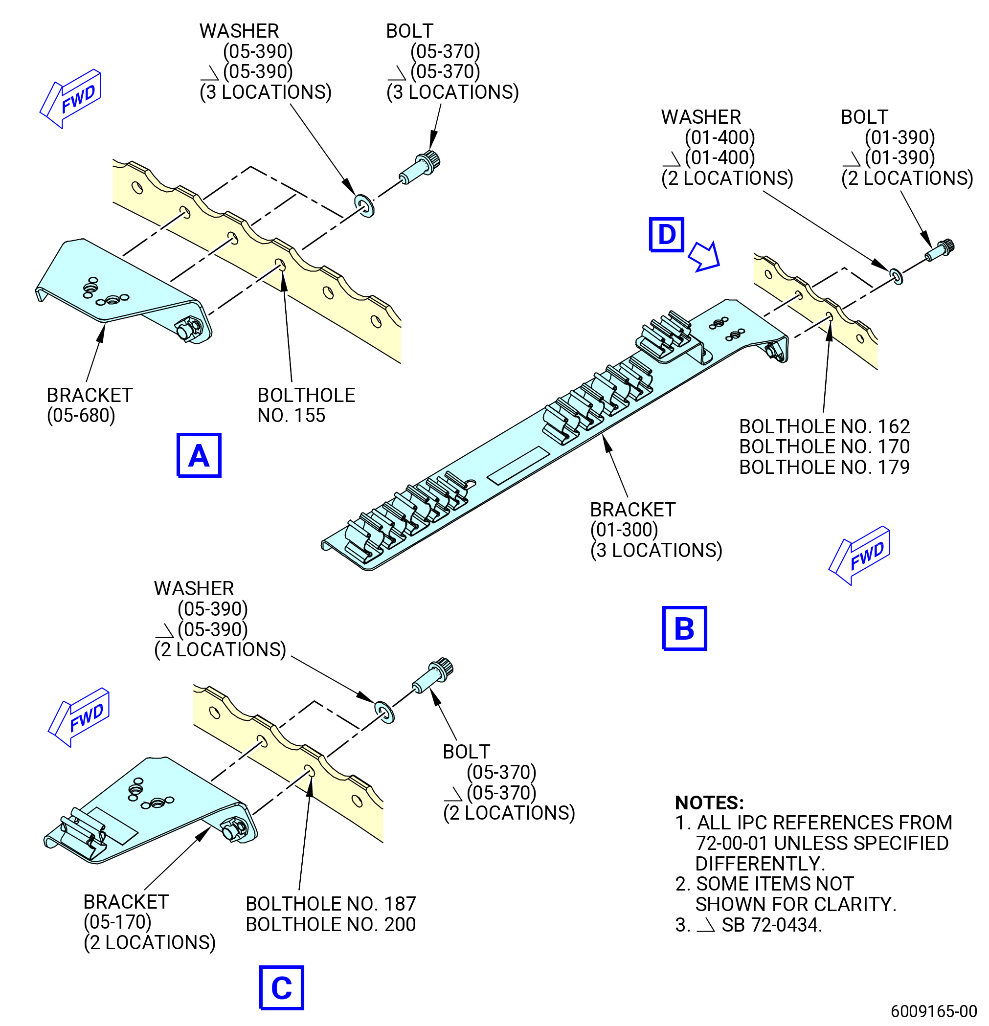
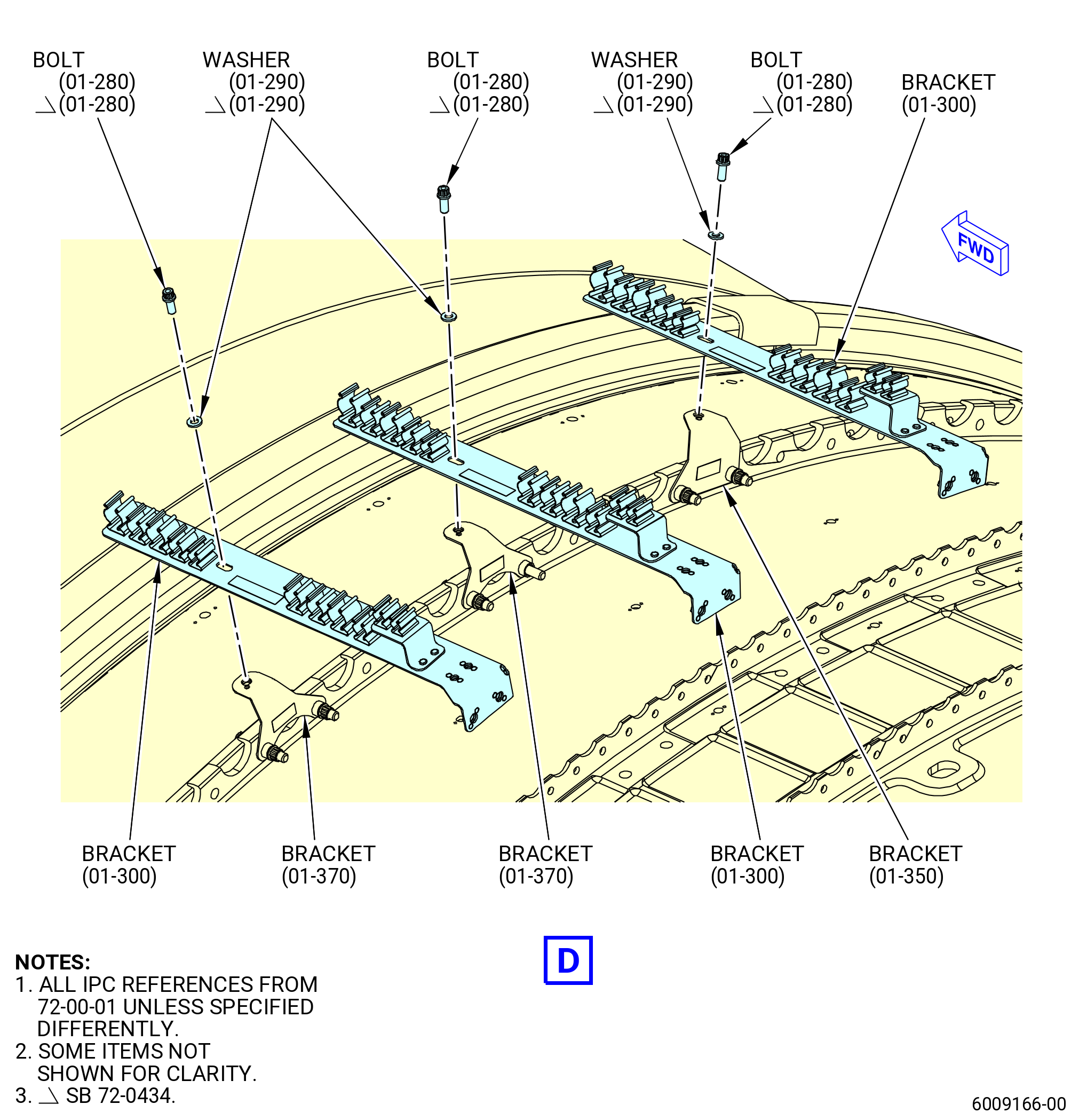
| (r) | Remove the tube PS3 and PS25 and electrical cable support brackets (support brackets) (01-300) (SIN 61419) from boltholes No. 161 and 162, No. 169 and 170, and No. 178 and 179. |
| (s) | Remove the support brackets (05-170) (SIN 61414) from boltholes No. 186 and 187, No. 193 and 194, and No. 199 and 200. |
| (t) | Remove the EMU support bracket (05-280) (SIN 65Z11) from boltholes No. 192 thru 194. |
| (u) | Remove the EMU support bracket (05-160) (SIN 65Z13) from boltholes No. 201 thru 203. |
| (v) | Remove the support brackets (10-320) (SIN 61311) from boltholes No. 232 and 233, and No. 237 and 238. |
| (w) | Remove the electrical bracket (bracket) (07-300) (SIN 6701B) from boltholes No. 240 and 241. |
| (x) | Remove the left PDOS support bracket (support bracket) (10-420) (SIN 5331C) from boltholes No. 246 and 247. |
| (y) | Remove the left PDOS support bracket (support bracket) (10-280) (SIN 53311) from boltholes No. 253 and 254. |
| (z) | Remove the bracket (01-180) (SIN 6881P) from boltholes No. 260 and 261. |
| (aa) | Remove the EAI fan case support bracket (support bracket) (01-140 , 71-00-01) (SIN 6101G) from boltholes No. 263 and 264. |
| (ab) | Remove the EAI fan case support bracket (support bracket) (01-130 , 71-00-01) (SIN 6101E) from boltholes No. 269 and 270. |
| Subtask 72-00-01-040-065 |
| O. | Continue with the disassembly of the fan stator assembly. Refer to TASK 72-21-00-040-803 (72-21-00, DISASSEMBLY 001). |