| GENX-1B ENGINE MANUAL | Dated: 10/31/2019 | |
| EM 72-21-00 , DISASSEMBLY 001 | ||
| FAN STATOR ASSEMBLY - DISASSEMBLY 001 | ||
| GENX-1B ENGINE MANUAL | Dated: 10/31/2019 | |
| EM 72-21-00 , DISASSEMBLY 001 | ||
| FAN STATOR ASSEMBLY - DISASSEMBLY 001 | ||
| * * * FOR ALL |
| TASK 72-21-00-040-803 |
| 1 . | General. |
| A. | This procedure gives instructions to disassemble the aft fan stator case assembly (fan stator assembly). This includes the forward containment fan case, mid outer acoustic liners (acoustic liners) (01-500) (SIN 83503) or (01-501) (SIN 83503), and the aft fan case on the fan stator assembly. |
| • |
|
| • |
|
| • |
|
| • |
|
| • |
|
| • |
|
| • |
|
| • |
|
| • |
|
| B. | This procedure begins with the fan stator assembly in the vertical position, forward end down, at the equivalent build status of TASK 72-00-01-040-805 (72-00-01, Disassembly 001). Refer to Figure 501. |
| 2 . | Tools, Equipment, and Materials. |
| NOTE: |
|
| A. | Tools and Equipment. |
| (1) | Special Tools. |
|
| (2) | Standard Tools and Equipment. None |
| (3) | Locally Manufactured Tools. None. |
| B. | Consumable Materials. |
| C. | Referenced Procedures. |
|
| D. | Expendable Parts. None. |
| 3 . | Procedure. |
| Subtask 72-21-00-040-130 |
| A. | Remove the doubler from the forward flange and aft flange. Refer to Figure 502 and Figure 503 and do as follows: |
| (1) | Put a mark to align the doubler location with the flange location. |
| (2) | Remove the nuts (item 37) and the screws (item 36) from the forward flange, keep the hardware. |
| (3) | Remove the nuts (item 37) and screws (item 40) from the aft flange, keep the hardware. |
| (4) | Use a non metallic spatula or equivalent to separate the doubler from the flange. If necessary, apply C02-053 penetrating oil, C02-039 penetrating oil or C02-018 penetrating oil to assist with doubler removal. Refer to TASK 70-80-02-800-013 (CONSUMABLE PRODUCTS ANTI-SEIZE COMPOUNDS, LUBRICANTS, OILS). |
| (5) | Remove the doublers items 30, 33, 34, 35, 41, 42, from the forward flange. |
| (6) | Remove the doublers items 38, 39, from the aft flange. |
| (7) | Use C04-035 isopropyl alcohol or a citrus based cleaner to clean the flange surface and bolt holes. Refer to TASK 70-21-23-110-053 (CLEANING METHOD NO. 23 - HAND-WIPE DEGREASING). |
| Subtask 72-21-00-040-057 |
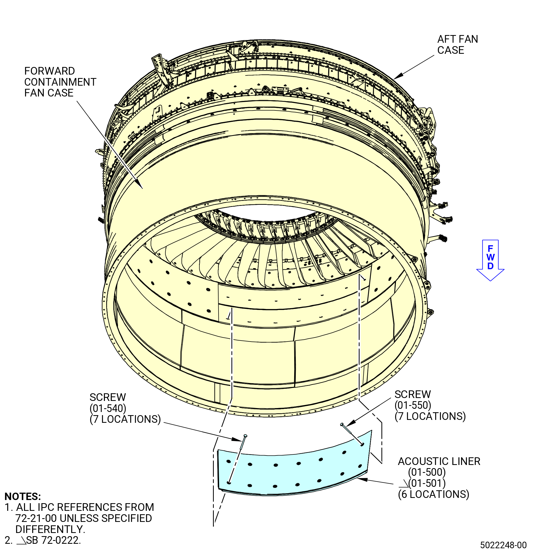
| B. | Remove the acoustic liner (01-500) (SIN 83503) or (01-501) (SIN 83503) from the forward containment fan case. Refer to Figure 504 and do as follows: |
| WARNING: |
|
| CAUTION: |
|
| (1) | Cut the C01-176 RTV from around the circumferential gap between the acoustic liner. |
| NOTE: |
|
| (2) | Remove the screws (01-540) (SIN 83521) and (01-550) (SIN 83522) from the forward row of holes. |
| (3) | Remove the screws from the aft row of holes. |
| (4) | Remove the acoustic liners from the forward containment fan case. |
| Subtask 72-21-00-040-058 |
| * * * PRE SB 72-0145( Removal of the Spacer Bolts without Safety Cable ) |
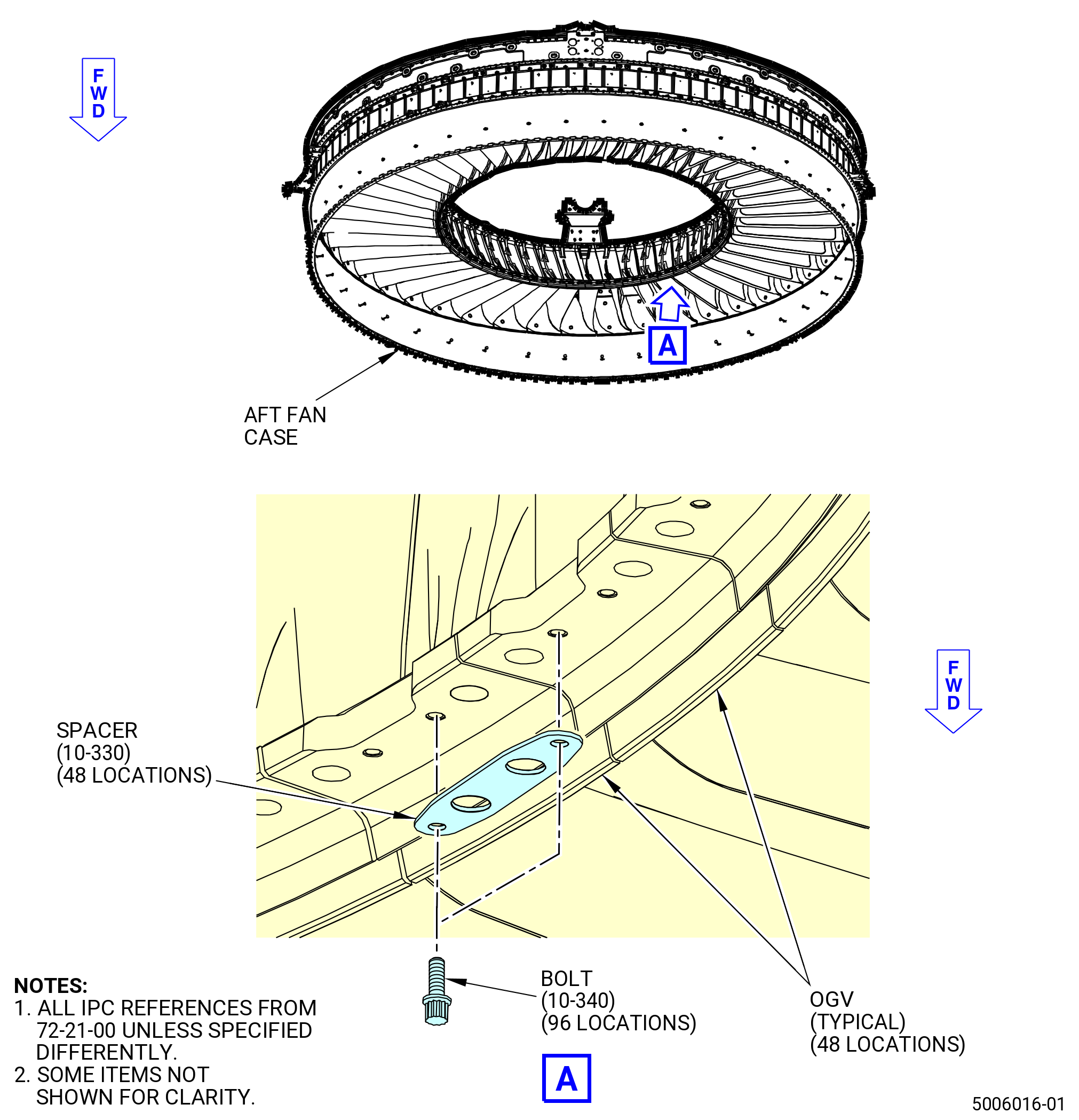
| C. | Remove the spacers (10-330) (SIN 8417B) from the OGVs 1-48. Refer to Figure 505 and do as follows: |
| (1) | Remove the 12 PT HD bolts (bolts) (10-340) (SIN 84023) from the forward inner base of the OGVs. |
| (2) | Remove the spacers from the OGVs. |
| * * * END PRE SB 72-0145 |
| Subtask 72-21-00-040-108 |
| * * * SB 72-0145( Removal of the Spacer Bolts with Safety Cable ) |
| C.A. | Remove the spacers (10-330) (SIN 8417B) or (11-330) (SIN 8417B) from the OGVs 1-48. Refer to Figure 505 and do as follows: |
| (1) | Remove the safety wire or safety cable from the bolts (10-340) (SIN 84023) or (11-340) (SIN 84023). |
| (2) | Remove the bolts (10-340) (SIN 84023) or (11-340) (SIN 84023) from the forward inner base of the OGVs. |
| (3) | Remove the spacers from the OGVs. |
| * * * END SB 72-0145 |
|
|
| Subtask 72-21-00-040-060 |
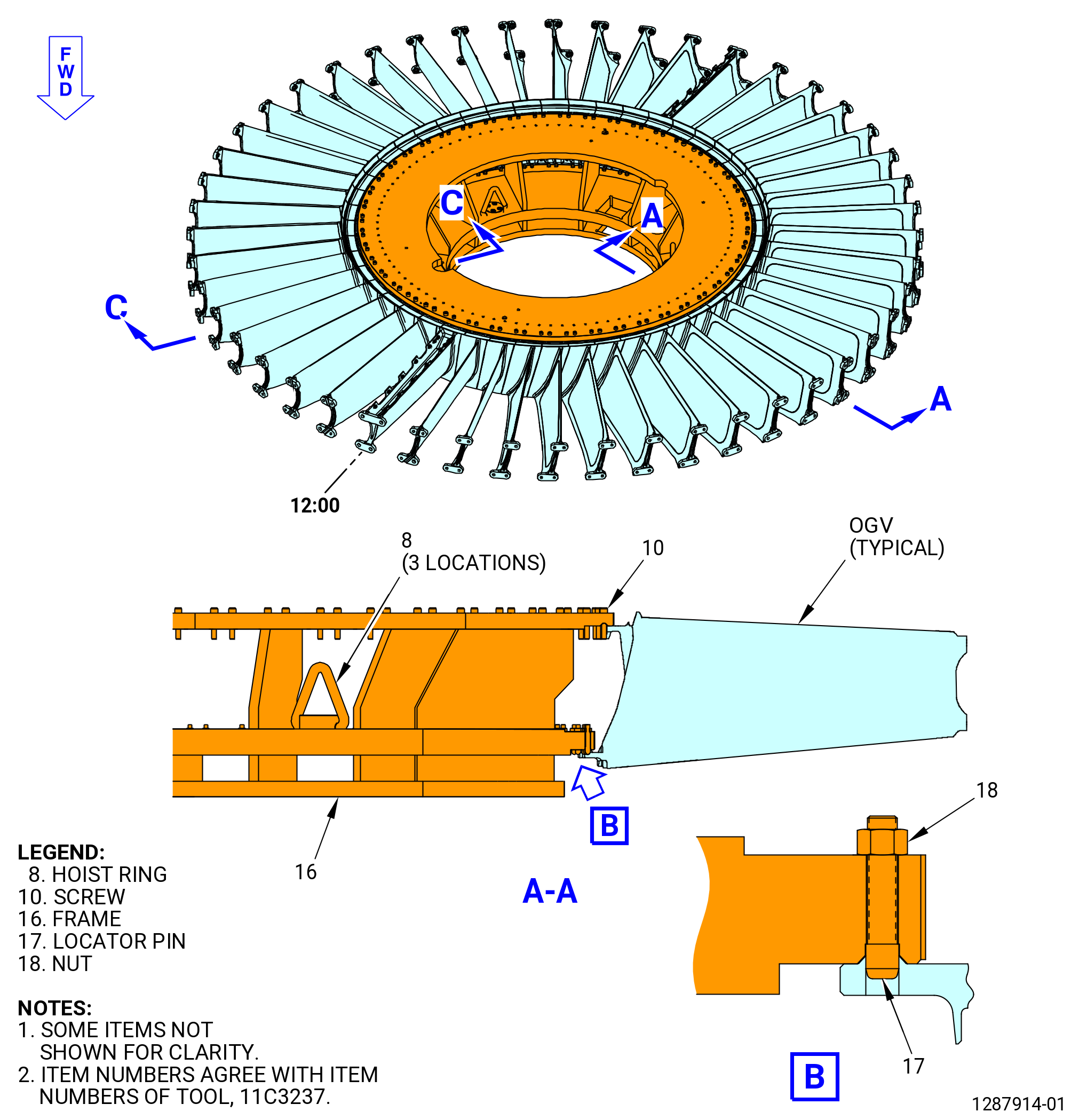
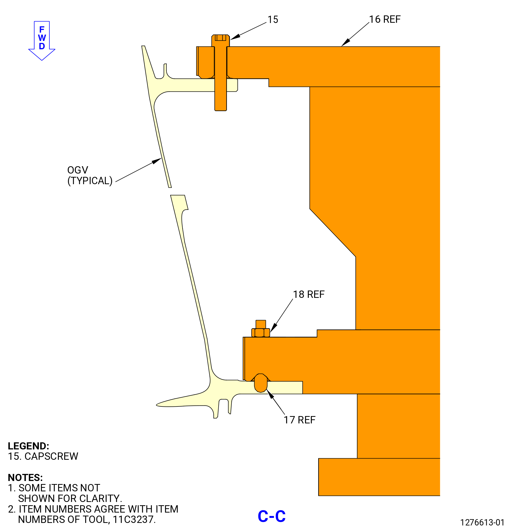
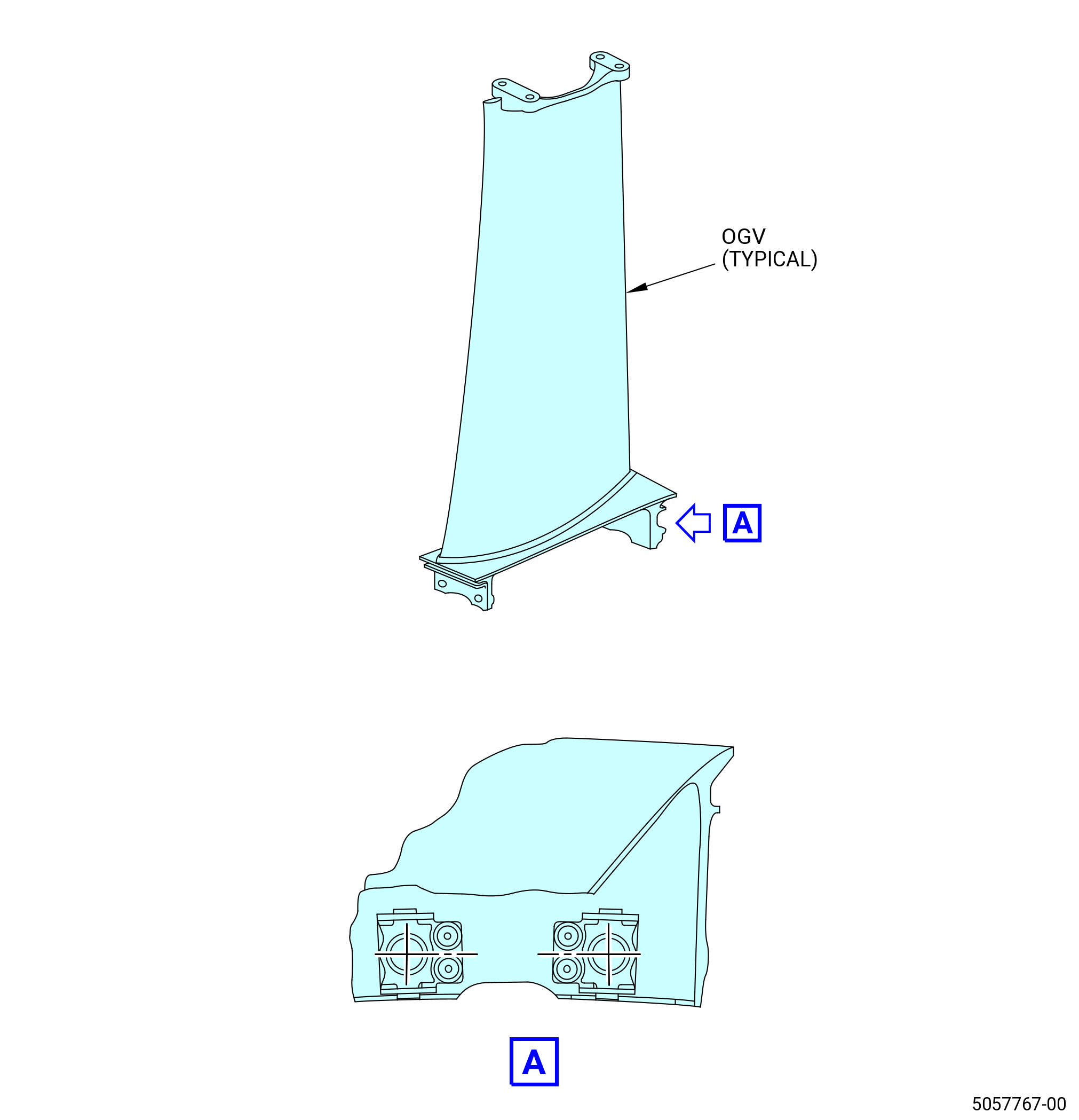
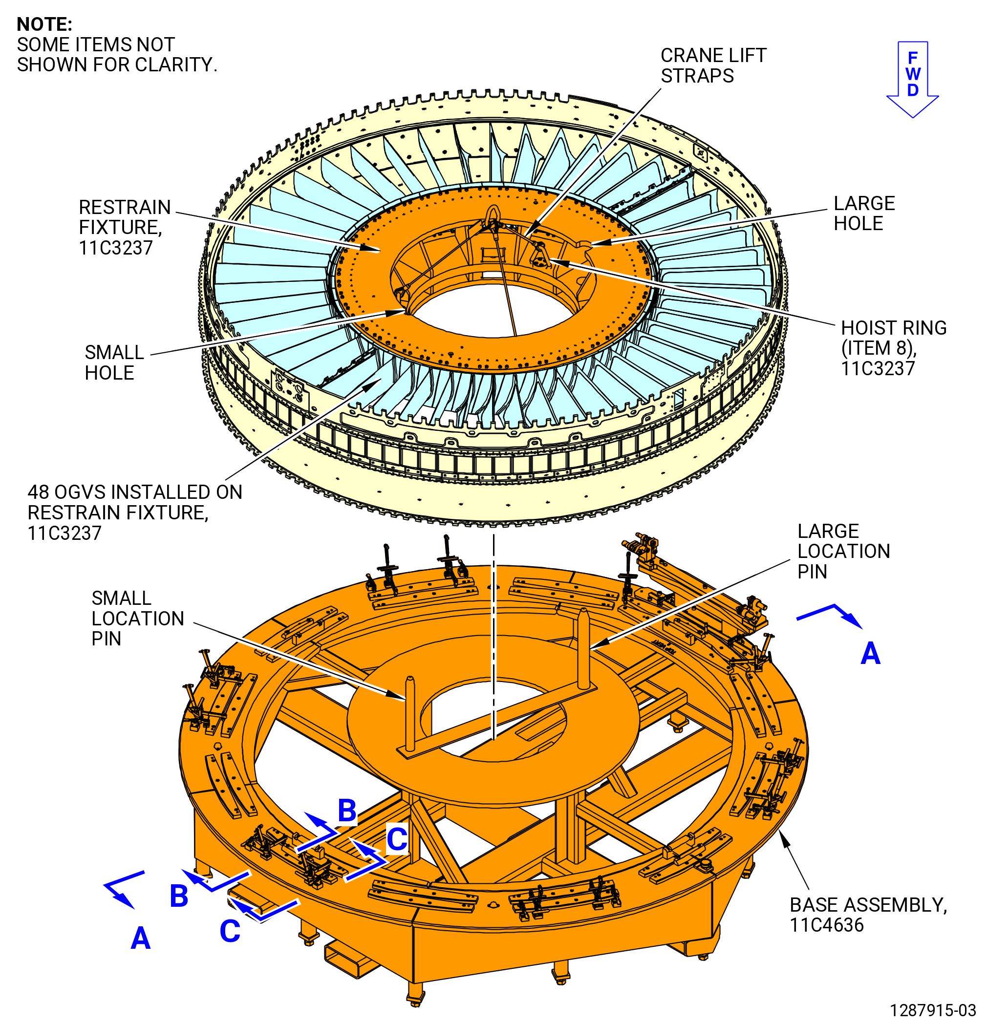
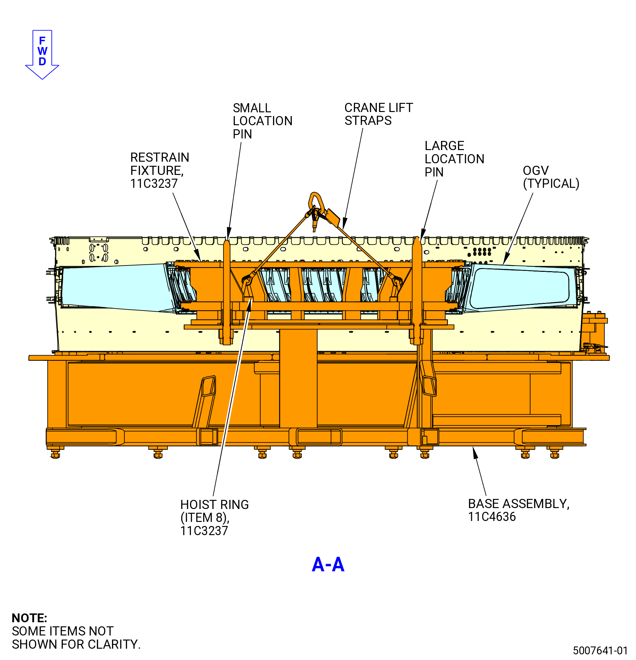
| D. | Attach the 11C3237 restrain fixture to the OGVs on the aft end of the aft fan case. Refer to Figure 506 and do as follows: |
| (1) | Attach an overhead lift sling to the hoist rings (item 8) at three locations. |
| WARNING: |
|
| (2) | Lift the 11C3237 restrain fixture and carefully lower the into the center of the OGVs on the aft fan case. |
| (3) | Align the TOP VERT mark with the upper OGV fan pylon (OGV 1 pylon) (10-290) (SIN 8400J) or (11-290) (SIN 8400J) at the 12:00 o'clock position. |
| CAUTION: |
|
| (4) | Attach each OGV to the 11C3237 restrain fixture as follows: |
| (a) | Use the locator pins (item 17) to align the OGVs at the bottom V groove on the frame (item 16) and use the top V groove to set the assembly position of the OGVs on the frame (item 16). |
| (b) | Make sure that the top vertical mark for the OGV 1 pylon is aligned at 12:00 o'clock position. |
| (c) | Attach the OGVs to the 11C3237 restrain fixture with the capscrews (item 10) at hole locations 9-16 on the aft inner mounting flange of the inner platform. |
| (d) | Attach the OGVs to the 11C3237 restrain fixture with the capscrews (item 15) at the remaining hole locations on the aft inner mounting flange of the inner platform. |
|
|
| Subtask 72-21-00-040-061 |
| E. | Remove the brackets and hardware from the aft fan case and the forward containment fan case forward ring flange (fan case forward ring). Refer to Figure 507 and do as follows: |
| (1) | Remove the self-locking nuts, bolts, and sleeve spacers (spacers) that connect the brackets to the fan case forward ring flange. |
| (2) | Remove the brackets from the fan case forward ring. |
| (3) | Remove the self-locking nuts, spacers, and bolts from all the remaining boltholes. |
| Subtask 72-21-00-040-062 |
| F. | Remove the aft fan case from the forward containment fan case. Refer to Figure 508 and do as follows: |
| (1) | Attach the lift slings on an overhead hoist to the hoist rings (item 8) of the 11C3237 restrain fixture. Refer to Figure 506. |
| WARNING: |
|
| (2) | Lift the aft fan case from the forward containment fan case. |
| (3) | Lower the aft fan case onto the 11C4636 base assembly and attach it as follows. Refer to Figure 508. |
| (a) | Make sure that the toggle clamp (item 37) and horizontal clamp (item 56) are in the open position. |
| (b) | Make sure that the forward flange is downward and faces the 11C4636 base assembly. |
| (c) | Make sure that the offset flange hole (on the forward flange of the aft fan case) is aligned with the dowel on the 11C4636 base assembly. |
| (d) | Make sure that the top vertical centerline at the 12:00 o'clock position is aligned with the top vertical centerline of the 11C4636 base assembly. |
| Subtask 72-21-00-040-065 |
| * * * PRE SB 72-0217( Titanium Upper Alignment Guides ) |
| G. | Remove the left/right upper alignment guides (01-200) (SIN 84408) and (01-210) (SIN 84409) from the aft fan case. Refer to Figure 509 and do as follows: |
| (1) | Remove the self-locking nuts (01-310) (SIN 84443) from the bolts (01-250) (SIN 8442C) on the upper alignment guides. |
| (2) | Remove the bolts and washers (01-290) (SIN 84436) from the inner panel of the aft fan case. |
| (3) | Remove the upper alignment guides from the aft fan case. |
| * * * END PRE SB 72-0217 |
| Subtask 72-21-00-040-129 |
| * * * SB 72-0217( Aluminum Upper Alignment Guides ) |
| G.A. | Remove the left/right upper alignment guides (01-201) (SIN 84408) and (01-211) (SIN 84409) from the aft fan case. Refer to Figure 509A and do as follows: |
| (1) | Remove the self-locking nuts (01-310) (SIN 84443) and washers (01-291) (SIN 84436) from the bolts (01-250) (SIN 8442C) on the upper alignment guides. |
| (2) | Remove the bolts and washers (01-291) (SIN 84436) from the inner panel of the aft fan case. |
| (3) | Remove the upper alignment guides from the aft fan case. |
| * * * END SB 72-0217 |
|
|
| Subtask 72-21-00-040-066 |
| H. | Remove the 1-48 OGV fairings from between the OGVs on the aft fan case. Refer to Figure 510 and do as follows: |
| WARNING: |
|
| CAUTION: |
|
| (1) | Cut the C01-176 RTV from each side of the OGV fairing. |
| NOTE: |
|
| (2) | Remove the screws from the OGV fairing. |
| (3) | Remove the OGV fairing from the aft fan case. |
| Subtask 72-21-00-040-067 |
| I. | Deleted. |
| Subtask 72-21-00-040-068 |
| J. | Deleted. |
| Subtask 72-21-00-040-069 |
| K. | Remove the surface cooler fairing (fairing) (01-530) (SIN 83506), lower right cowl seals (01-400) (SIN 84151) or (01-401) (SIN 84151) or (01-402) (SIN 84151), and lower left cowl seals (01-410) (SIN 84152) or (01-411) (SIN 84152) or (01-412) (SIN 84152) from the aft fan case and OGV 25 pylon (10-300) (SIN 8400K) or (11-300) (SIN 8400K). Refer to Figure 513 and do as follows: |
| WARNING: |
|
| CAUTION: |
|
| (1) | Deleted. |
| NOTE: |
|
| (2) | Remove the lower right and left cowl seals from the aft fan case. |
| (3) | Remove the screws (01-560) (SIN 83523) that attach the fairing to the aft fan case at the 6:00 o'clock position. |
| (4) | Remove the fairing from the aft fan case and OGV 25 pylon. |
| Subtask 72-21-00-040-092 |
| L. | Remove and discard the insulation blanket (01-720) (SIN 844A5) from the lower firewall (01-370) (SIN 84501) or (01-371) (SIN 84501) or (01-372) (SIN 84501). Refer to Figure 511. |
| Subtask 72-21-00-040-093 |
| * * * SB 72-0035( Introduction of the Fire Shields ) |
| M. | Remove and discard the fire shields (01-680) (SIN 844A1), (01-690) (SIN 844A2), (01-700) (SIN 844A3), and (01-710) (SIN 844A4) from the upper firewall (01-151) (SIN 84401) or (01-152) (SIN 84401). Refer to Figure 512. |
| NOTE: |
|
| * * * END SB 72-0035 |
|
| Subtask 72-21-00-040-073 |
| N. | Remove the oil vent hose tube (tube hose) (01-090 , 79-22-30) (SIN 46004) or (01-091 , 79-22-30) (SIN 46004), from the upper firewall (01-150) (SIN 84401) or (01-151) (SIN 84401) or (01-152) (SIN 84401). Refer to Figure 514 and do as follows: |
| (1) | Remove the self-locking nut (46040) from the bolt that attaches the oil tube/hose (46000) to the aft fan case. |
| (2) | Remove the bolt (46021) from the loop cush clamp (46080) and the bracket (46010). |
| (3) | Remove the oil tube/hose from the upper firewall and the aft fan case. |
| (4) | Remove and discard the gaskets (01-070 , 79-22-30) (SIN 46053). |
| Subtask 72-21-00-040-131 |
| O. | Remove the air duct (01-030 , 75-11-20) (SIN 61004) from the upper firewall (01-150) (SIN 84401) or (01-151) (SIN 84401) or (01-152) (SIN 84401). Refer to Figure 515 and do as follows: |
| (1) | Remove the machine bolts (bolts) (01-160 , 75-11-20) (SIN 61024) that attach the air duct (01-030 , 75-11-20) (SIN 61004) to the support bracket (01-180 , 75-11-20) (SIN 6101C) with the retaining strap (retainer strap) (01-170 , 75-11-20) (SIN 61084). |
| (2) | Loose the coupling V retainers (01-190 , 75-11-20) (SIN 61081) bolts located on the upper and lower part of the air duct. |
| (3) | Remove the coupling V retainers (01-190 , 75-11-20) (SIN 61081). |
| (4) | Remove the air duct (01-030 , 75-11-20) (SIN 61004). |
| (5) | Remove the seal rings (01-200 , 75-11-20) (SIN 61051) from the air duct. |
| Subtask 72-21-00-220-047 |
| (a) | Examine the seal rings (01-200 , 75-11-20) (SIN 61051) for damage. |
| (b) | If the seal rings are damaged, replace them. |
| Subtask 72-21-00-040-132 |
| * * * FOR ALL.ALL |
| (6) | Remove the bolts (01-160 , 75-11-20) (SIN 61024) that attach the support bracket (01-180 , 75-11-20) (SIN 6101C) to the upper firewall (01-150) (SIN 84401) or (01-151) (SIN 84401) or (01-152) (SIN 84401). |
| (7) | Remove the bolts (01-160 , 75-11-20) (SIN 61024) that attach the support bracket (01-180 , 75-11-20) (SIN 6101C) to the upper firewall (01-150) (SIN 84401) or (01-151) (SIN 84401) or (01-152) (SIN 84401). |
| (8) | Remove the bracket from the upper firewall. |
| Subtask 72-21-00-040-076 |
| P. | Remove the power door opening system (PDOS) brackets (25-010 , 71-00-00) (SIN 95111) and (25-020 , 71-00-00) (SIN 95112) from the aft fan case. Refer to Figure 516 and do as follows: |
| (1) | Remove the self-locking nuts (25-050 , 71-00-00) (SIN 95140) and washers (25-040 , 71-00-00) (SIN 95130) from the PDOS brackets. |
| (2) | Remove the bolts (25-030 , 71-00-00) (SIN 95121) and washers from the inner side of the aft fan case. |
| (3) | Remove the PDOS brackets from the aft fan case. |
| Subtask 72-21-00-040-107 |
| Q. | Continue to disassemble the fan stator assembly. Refer to TASK 72-21-00-040-804 (72-21-00, DISASSEMBLY 002 - CONFIGURATION 01) or TASK 72-21-00-040-805 (72-21-00, DISASSEMBLY 002 - CONFIGURATION 02). |