| GENX-1B ENGINE MANUAL | Dated: 02/21/2020 | |
| EM 72-21-00 , DISASSEMBLY 002 | ||
| FAN STATOR ASSEMBLY - DISASSEMBLY 002 - CONFIGURATION 01 | ||
| GENX-1B ENGINE MANUAL | Dated: 02/21/2020 | |
| EM 72-21-00 , DISASSEMBLY 002 | ||
| FAN STATOR ASSEMBLY - DISASSEMBLY 002 - CONFIGURATION 01 | ||
| * * * FOR ALL |
| TASK 72-21-00-040-804 |
| 1 . | General. |
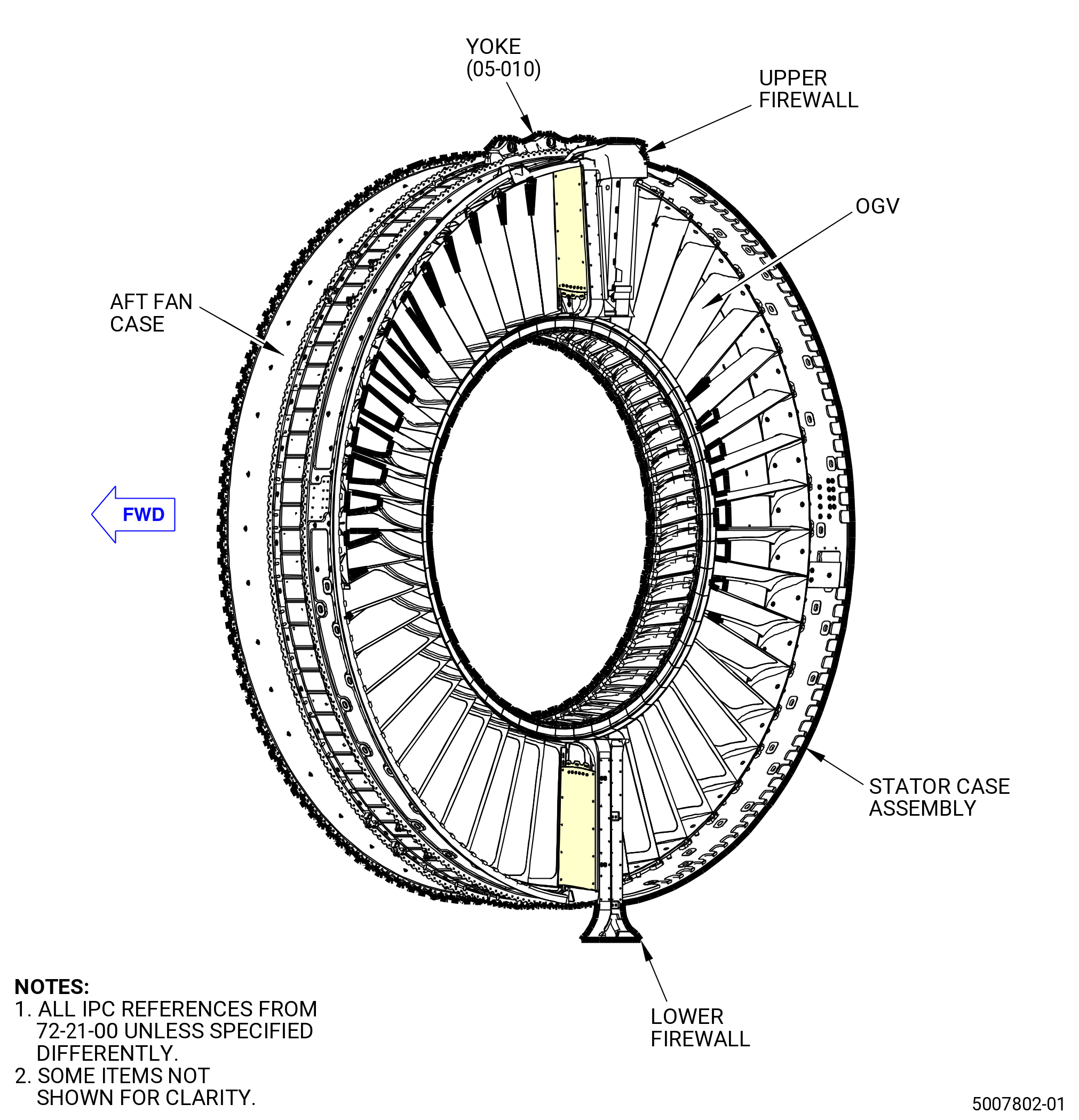
| A. | This procedure gives instructions to disassemble the after fan stator case assembly (stator case assembly) (01-020 , 72-00-01) (SIN 00109) or (01-021 , 72-00-01) (SIN 00109). Refer to Figure 501. |
| B. | This procedure begins with the fan stator assembly in vertical position, forward end down, at the equivalent build status of TASK 72-21-00-040-803 (72-21-00, DISASSEMBLY 001) . |
| C. | Before this procedure is done, read the assembly and disassembly techniques section. Refer to TASK 70-10-00-800-009 (ASSEMBLY AND DISASSEMBLY TECHNIQUES) . |
| 2 . | Tools, Equipment, and Materials. |
| NOTE: |
|
| A. | Tools and Equipment. |
| (1) | Special Tools. |
| (2) | Standard Tools and Equipment. |
|
| (3) | Locally Manufactured Tools. None. |
| B. | Consumable Materials. |
|
| C. | Referenced Procedures. |
|
| D. | Expendable Parts. None. |
| 3 . | Procedure. |
| Subtask 72-21-00-040-094 |
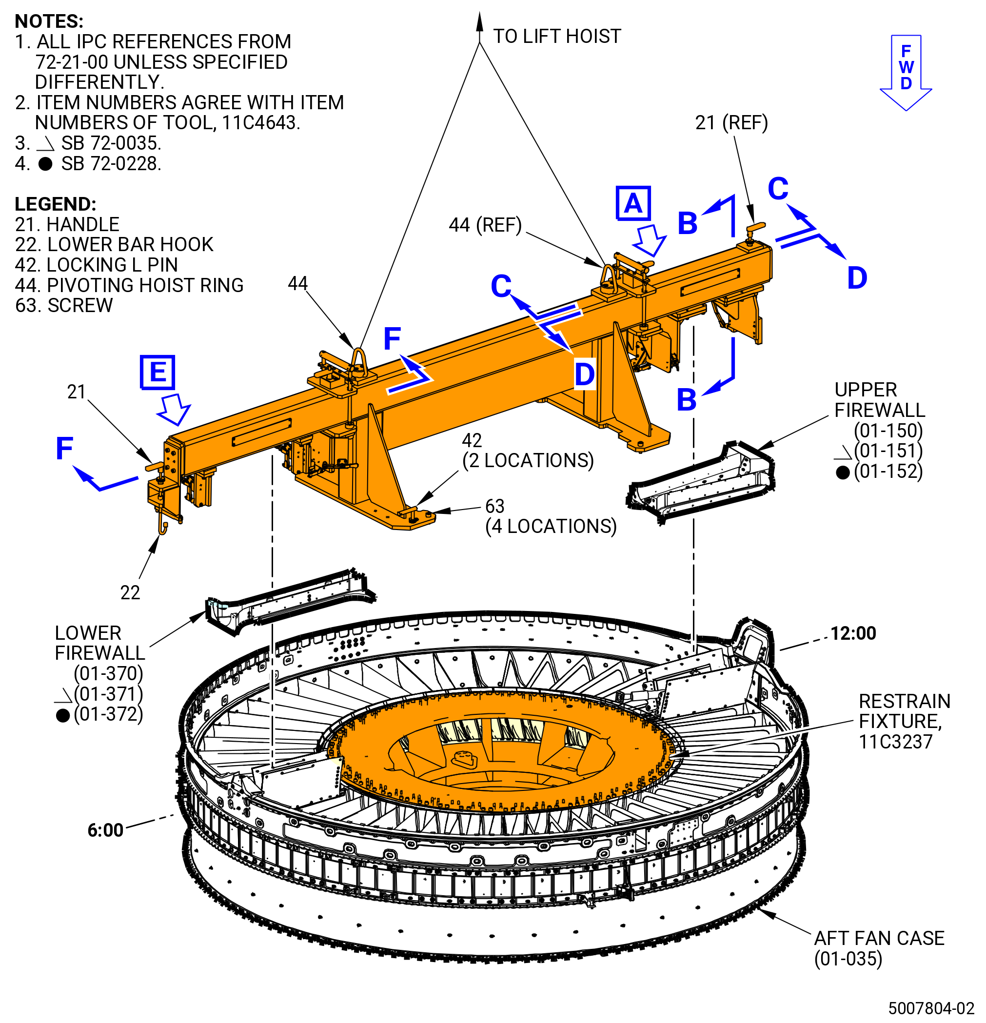
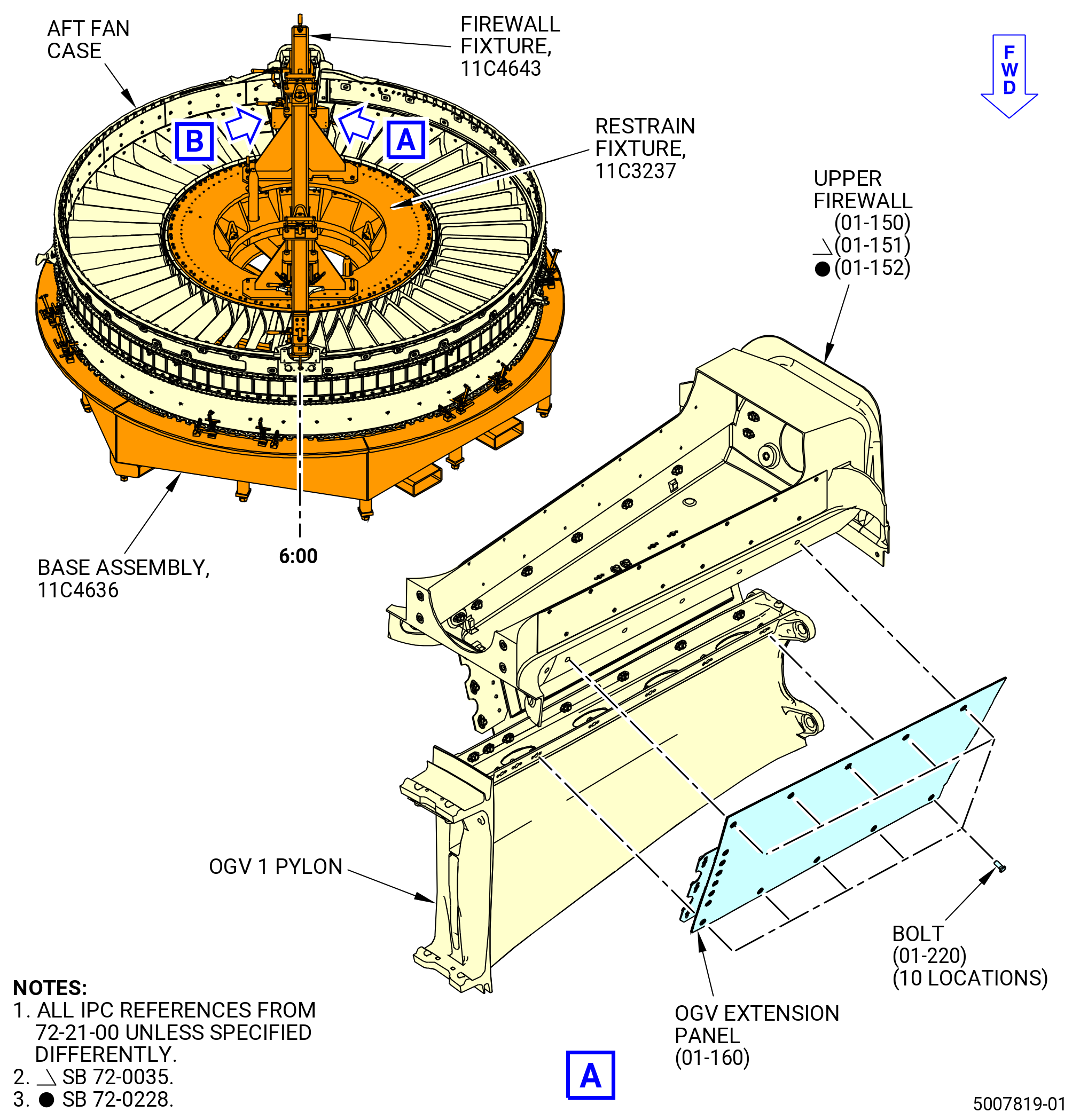
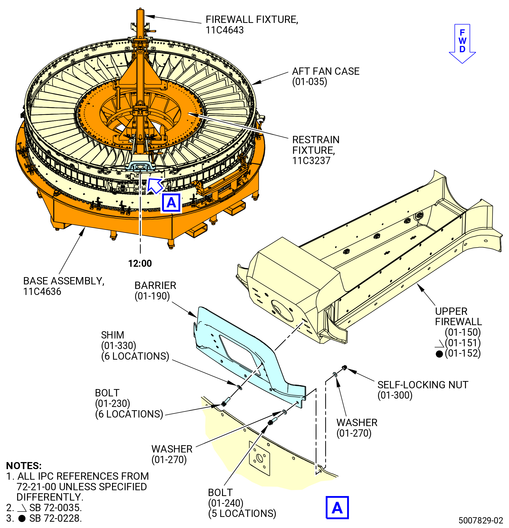
| A. | Install the 11C4643 firewall fixture on the upper firewall (01-150) (SIN 84401) or (01-151) (SIN 84401) or (01-152) (SIN 84401) and the lower firewall (01-370) (SIN 84501) or (01-371) (SIN 84501) or (01-372) (SIN 84501). Refer to Figure 502 and do as follows: |
| (1) | Prepare to attach the 11C4643 firewall fixture to the upper and lower firewall as follows: |
| WARNING: |
|
| (a) | Attach an overhead hoist to the pivoting hoist rings (item 44) and lift the 11C4643 firewall fixture. |
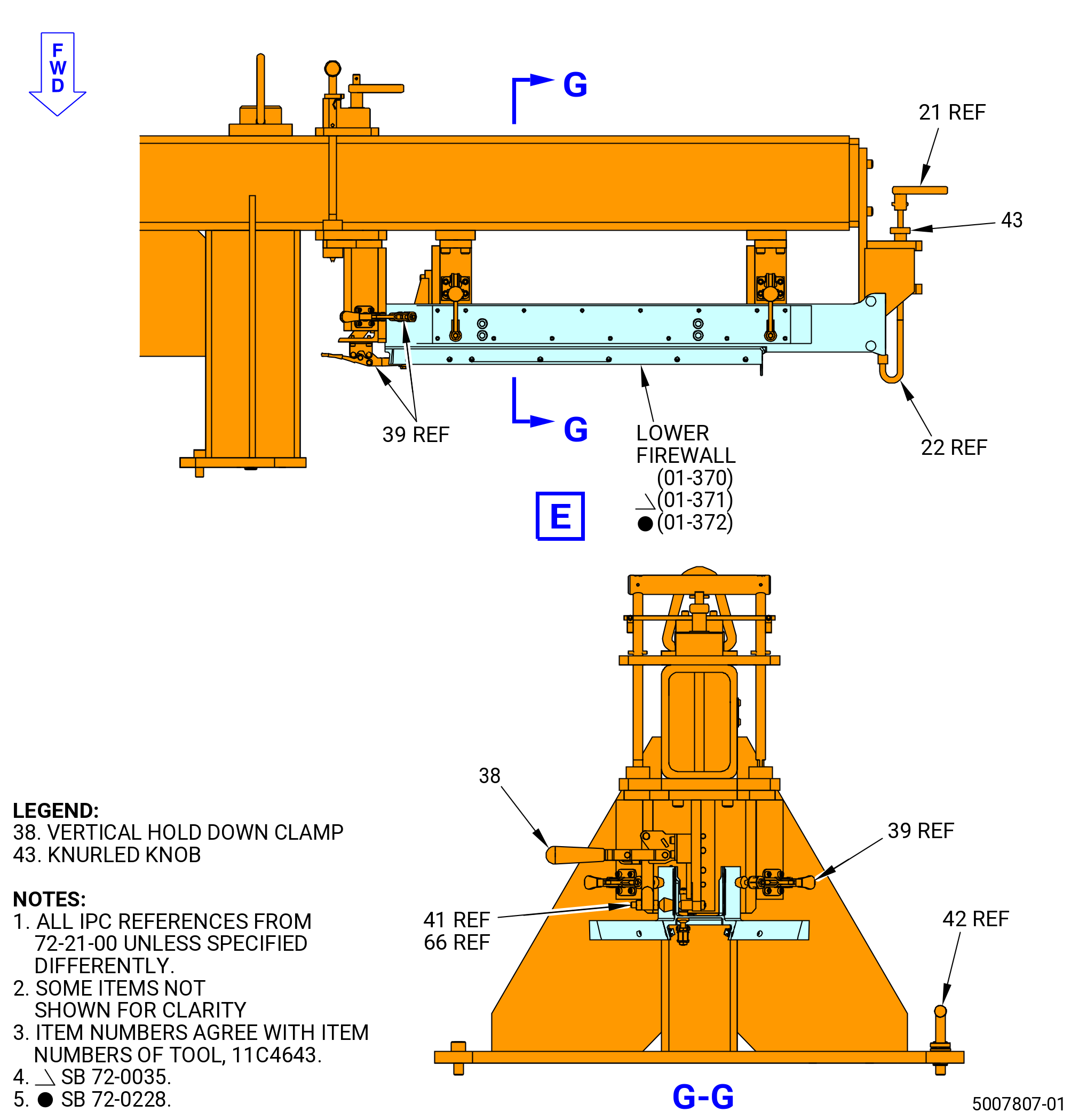
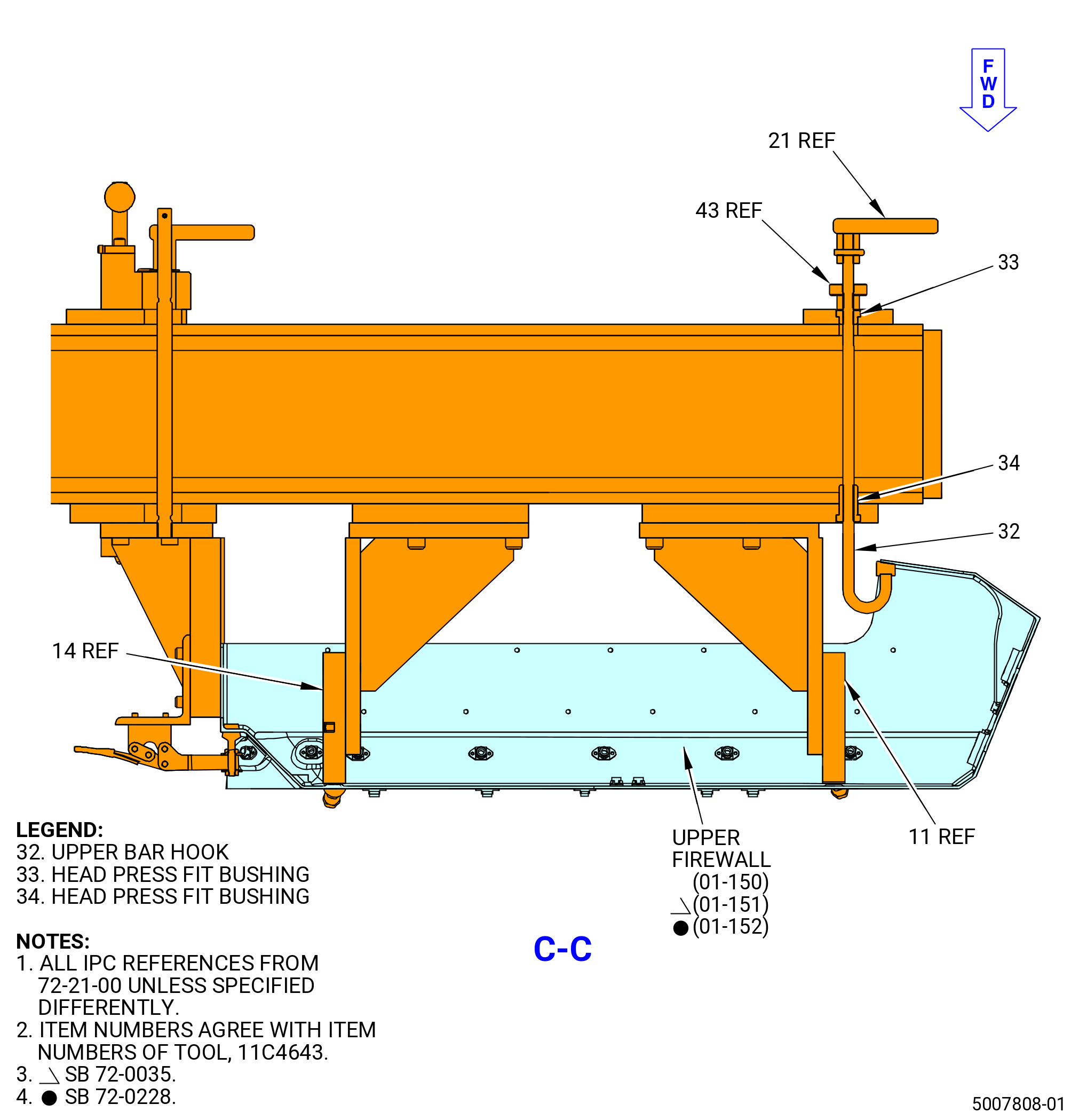
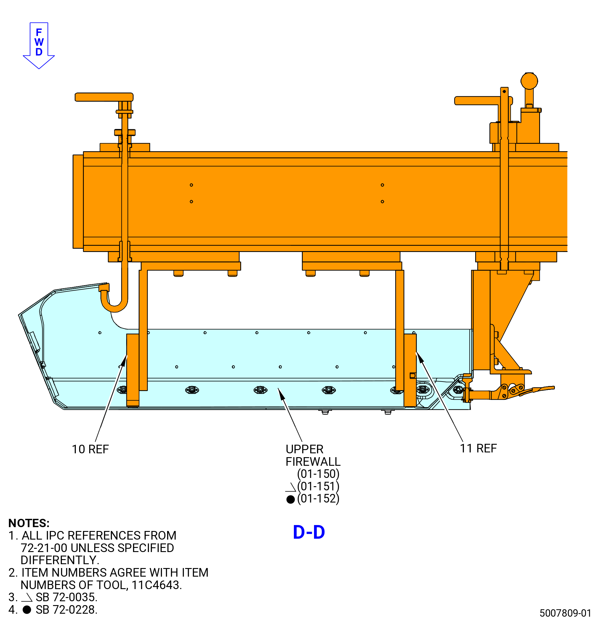
| (b) | Make sure to disengage all the toogle clamps (item 31), vertical hold down clamps (item 38), and horizontal spanners (item 39), then loosen the knurled knobs (item 43) to release the lower bar hook (item 22) and upper bar hook (item 32) through the head press fit bushings (item 33 and 34) to let the attachment of the lower and upper firewalls to the clamping mechanisms. |
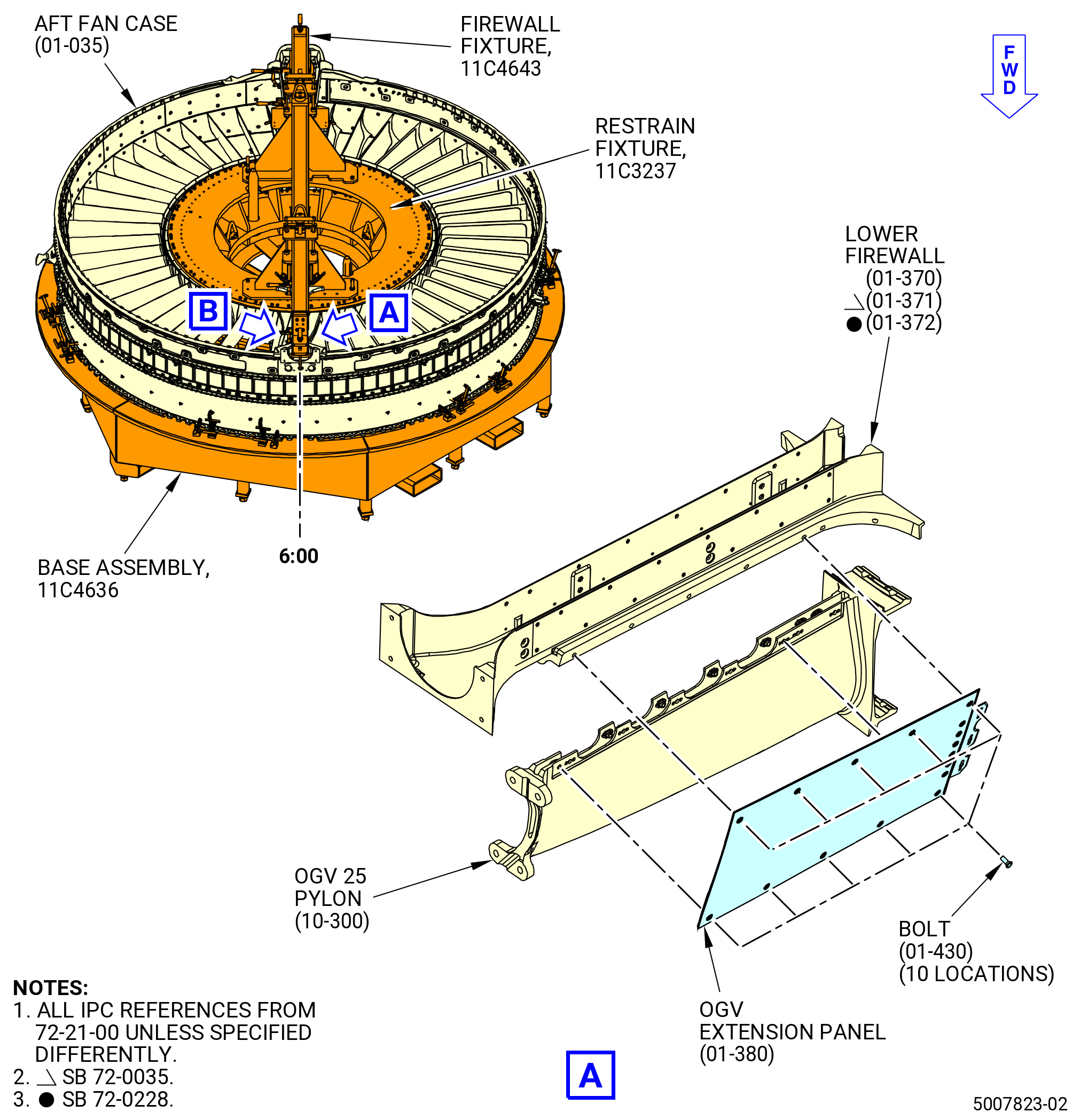
| (c) | Put the 11C4643 firewall fixture on the 11C3237 restrain fixture that is already seated on 11C4636 base assembly. |
| (d) | Lower the 11C4643 firewall fixture to align it on the top surface of the 11C3237 restrain fixture, and attach it with the two locking L pins (item 42) and the four socket head cap screws (screws) (item 63). |
| (2) | Attach the 11C4643 firewall fixture to the upper and lower firewalls. Refer to Figure 502 and do as follows: |
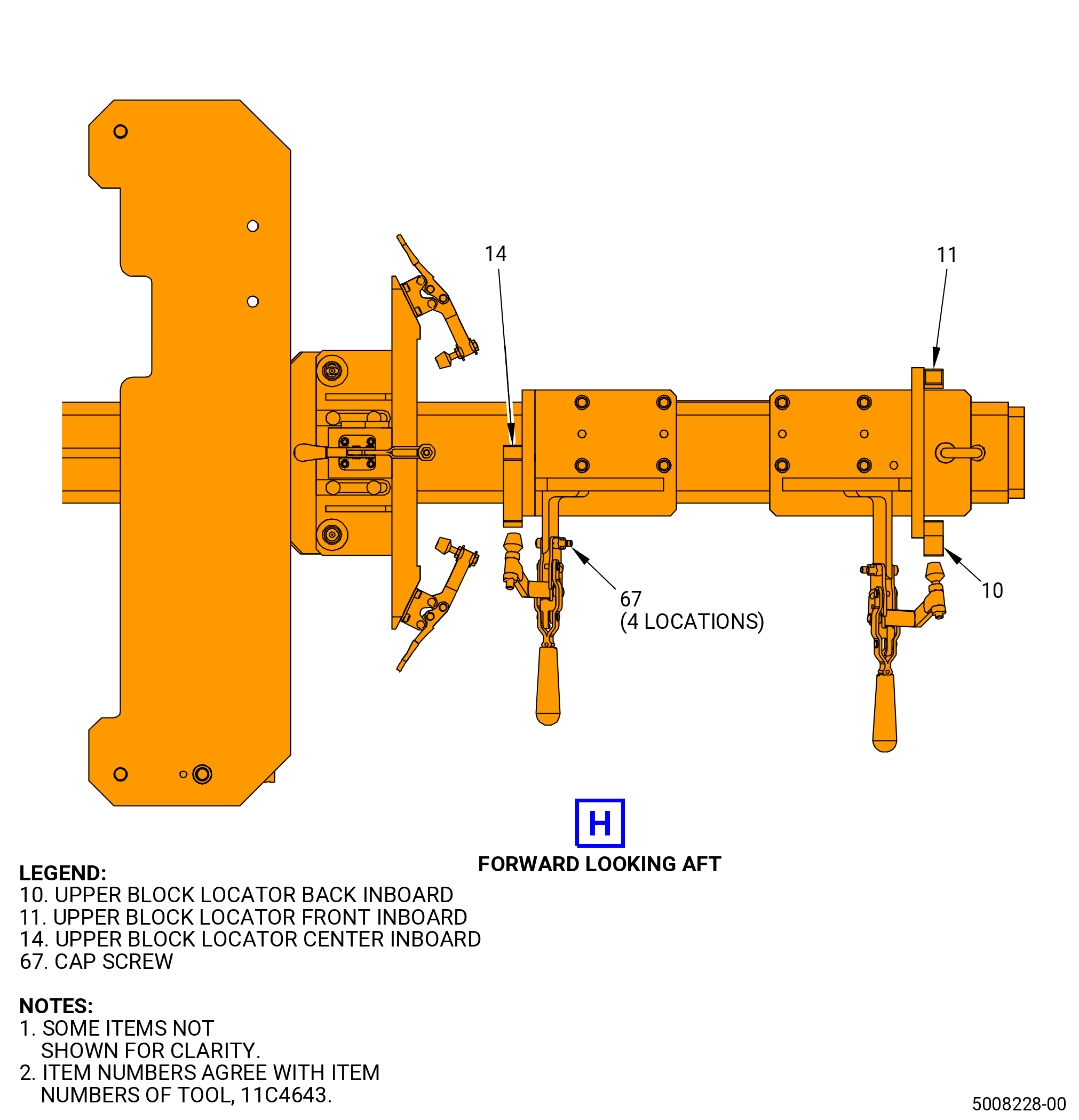
| (a) | Carefully lower the 11C4643 firewall fixture until the three protuberant points on the internal surface of the lower firewall touch the locator block pin (item 18) and the locator lower pins (item 20) and until the three protuberant points on the internal surface of the upper firewall touch the upper block locator back, front, and center inboards (items 10, 11, and 14). |
| (b) | Carefully adjust the 11C4643 firewall fixture to make sure there is contact between the surfaces of the two protuberant points on the side of the lower firewall and the locator center pin (item 19), and contact between the two protuberant points on the side of the upper firewall and the upper block locator back and center inboard (item 10 and 14). |
| (c) | When the protuberant points of the lower firewall get in contact, turn the handle (item 21) inwards to close the lower bar hook (item 22) and pull it up to support the bottom surface of the lower firewall, then hand tighten the knurled knob (item 43) to secure firmly the position of the lower bar hook (item 22). |
| (d) | When the protuberant points of the upper firewall get in contact, turn the handle (item 21) inwards to close the upper bar hook (item 32) and pull it up to support the internal top surface of the upper firewall, then hand tighten the knurled knob (item 43) to secure the position of the upper bar hook (item 32). |
| (e) | Complete the clamping of the lower firewall by engaging the two vertical hold down clamps (item 38) and the three horizontal spanners (item 39). If necessary, adjust the position of the spindles (item 41) with the hexagonal nuts (item 66). |
| (f) | Complete the clamping of the upper firewall by engaging the toogle clamps (item 31) and three horizontal spanners (item 39). If necessary, adjust the position of spindles (item 41) with the hexagonal nuts (item 66). |
| NOTE: |
|
| Subtask 72-21-00-040-095 |
| (3) | Deleted. |
| Subtask 72-21-00-040-109 |
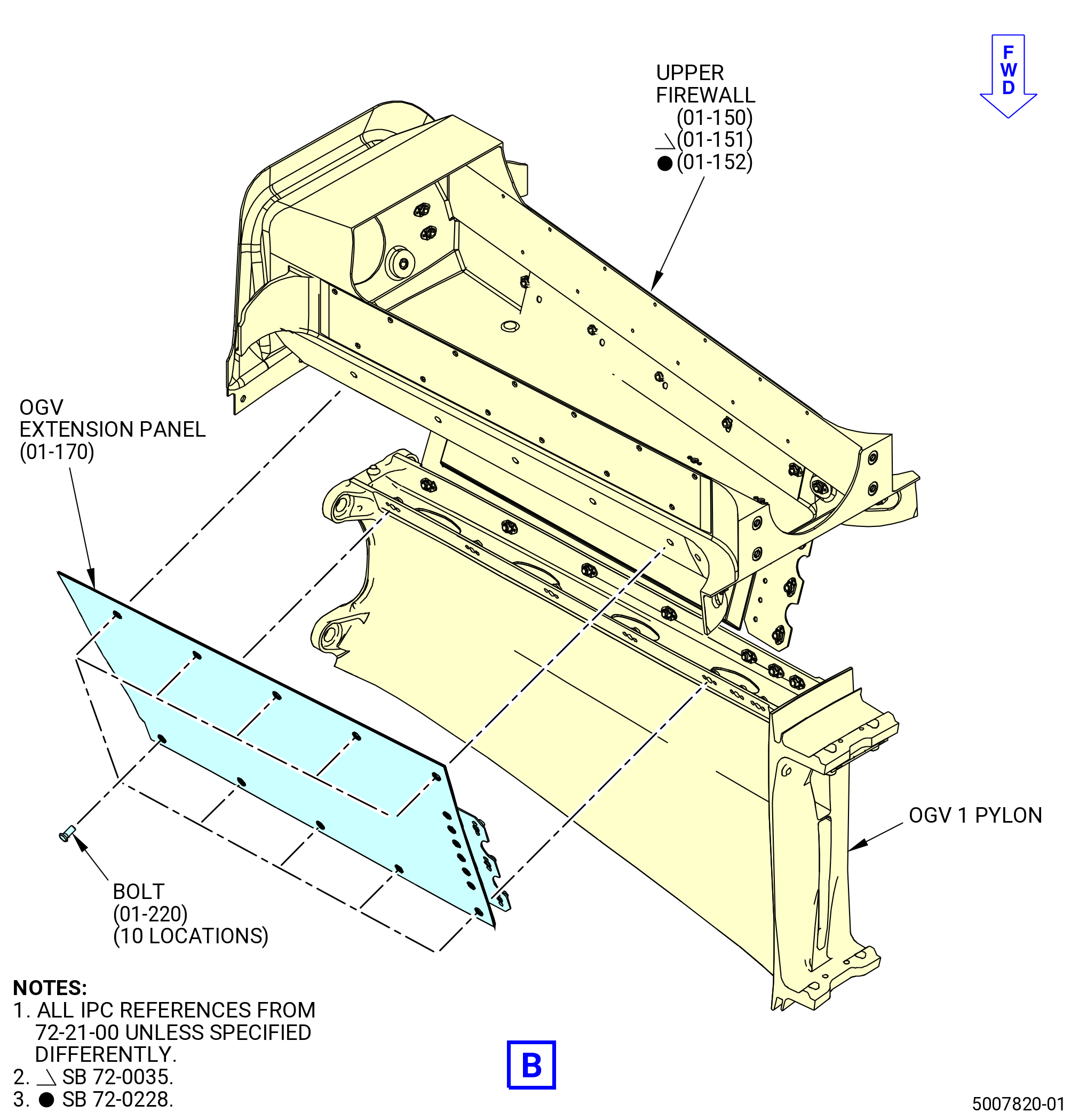
| B. | Remove the OGV upper right extension panel (OGV extension panel) (01-160) (SIN 84402) and OGV upper left extension panel (OGV extension panel) (01-170) (SIN 84403) from the upper firewall (01-150) (SIN 84401) or (01-151) (SIN 84401) or (01-152) (SIN 84401). Refer to Figure 503 and do as follows: |
| WARNING: |
|
| CAUTION: |
|
| (1) | Cut the C01-176 RTV from upper side of the OGV extension panel and the aft outer acoustic panel. |
| NOTE: |
|
| (2) | Remove the torx recess bolts (bolts) (01-220) (SIN 84420) from the OGV extension panels. |
| (3) | Remove the OGV extension panels from the upper firewall. |
| Subtask 72-21-00-040-110 |
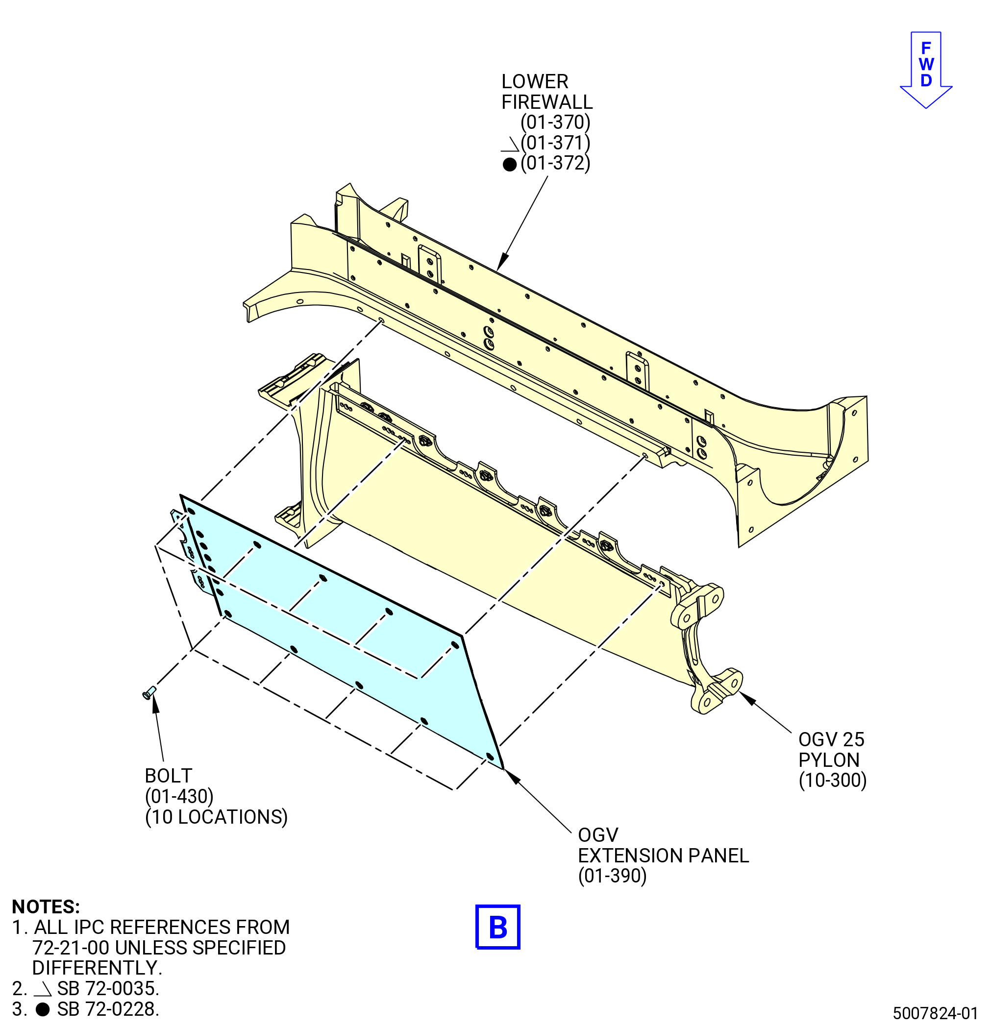
| C. | Remove the OGV lower right extension panel (OGV extension panel) (01-380) (SIN 84502) and OGV lower left extension panel (OGV extension panel) (01-390) (SIN 85403) from the aft fan case (01-035) (SIN 84100) at OGV 25 pylon (10-300) (SIN 8400K). Refer to Figure 504 and do as follows: |
| WARNING: |
|
| CAUTION: |
|
| (1) | Cut the C01-176 RTV from joints between the OGVs. |
| NOTE: |
|
| (2) | Remove the torx recess bolts (bolts) (01-430) (SIN 84520) from the OGV extension panels. |
| (3) | Remove the OGV extension panels from the OGV 25 pylon. |
| Subtask 72-21-00-040-096 |
| * * * PRE SB 72-0215( Lower Firewall without Bumper ) |
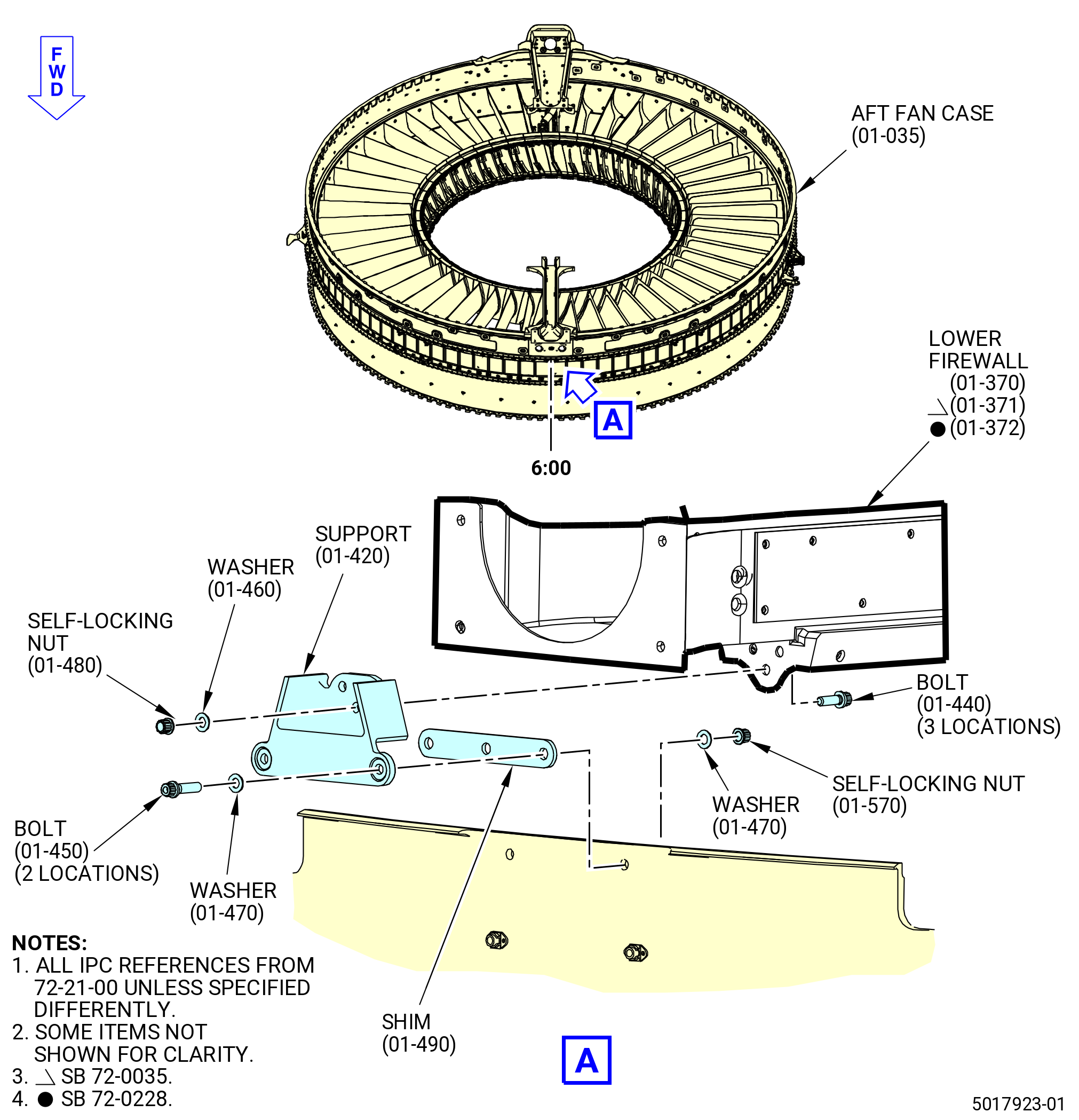
| D. | Remove the support (01-420) (SIN 84508) from the lower firewall (01-370) (SIN 84501) or (01-371) (SIN 84501) or (01-372) (SIN 84501) and the aft fan case (01-035) (SIN 84100). Refer to Figure 505 and do as follows: |
| (1) | Remove the self-locking nuts (84541, 84542) and washers (84532, 84533) from the bolts on the aft fan case. |
| (2) | Remove the self-locking nuts and washers from the bolts (84521, 84522) on the support. |
| (3) | Remove the bolts from the lower firewall and the support. |
| (4) | Remove the support from lower firewall support and the aft fan case. |
| * * * END PRE SB 72-0215 |
| Subtask 72-21-00-040-127 |
| * * * SB 72-0215( Lower Firewall with Bumper ) |
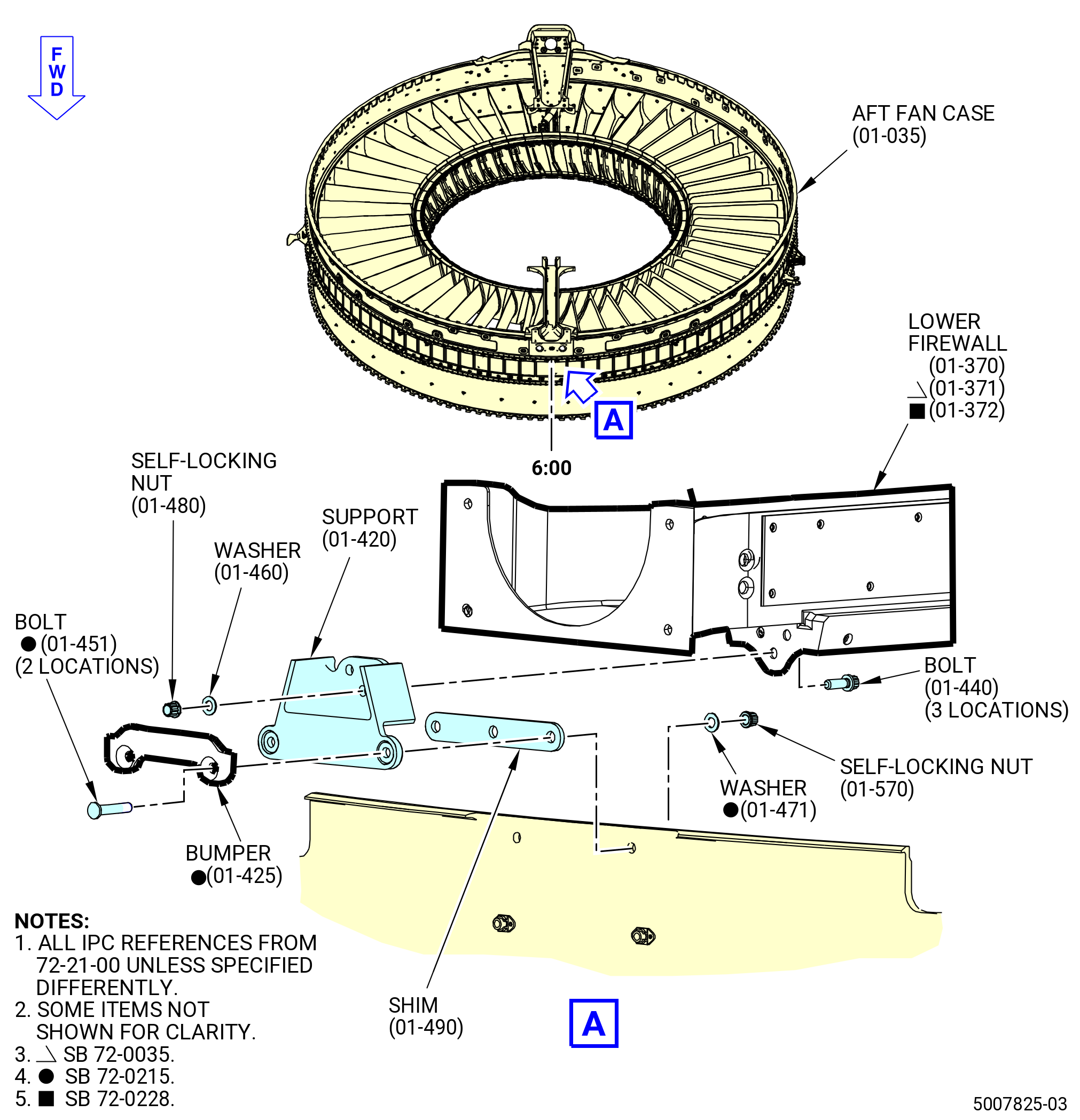
| D.A. | Remove the support (01-420) (SIN 84508) from the lower firewall (01-370) (SIN 84501) or (01-371) (SIN 84501) or (01-372) (SIN 84501) and aft fan case (01-035) (SIN 84100). Refer to Figure 505 and do as follows: |
| (1) | Remove the self-locking nuts (01-480) (SIN 84541) and (01-570) (SIN 84542) and washers (01-460) (SIN 84532) and (01-471) (SIN 84533) from the bolts on the aft fan case. |
| (2) | Remove the self-locking nuts and washers from the bolts (01-440) (SIN 84521) and (01-451) (SIN 84522) on the support. |
| (3) | Remove the bumper (01-425) (SIN 84518). |
| (4) | Remove the bolts from the lower firewall and the support. |
| (5) | Remove the support from the lower firewall support and aft fan case. |
| * * * END SB 72-0215 |
|
|
| Subtask 72-21-00-040-097 |
| E. | Remove the vapor barrier (barrier) (01-190) (SIN 84405) from the aft fan case (01-035) (SIN 84100) and the upper firewall (01-150) (SIN 84401) or (01-151) (SIN 84401) or (01-152) (SIN 84401). Refer to Figure 506 and do as follows: |
| WARNING: |
|
| CAUTION: |
|
| (1) | Cut the C01-176 RTV from the joints between the barrier and the upper firewall. |
| NOTE: |
|
| (2) | Remove the self-locking nuts (84441) and washers (84432) from the bolts (84422) on the aft fan case. |
| (3) | Remove the bolts from the barrier and the upper firewall. |
| (4) | Remove the barrier from the upper firewall and the aft fan case. |
| Subtask 72-21-00-040-098 |
| WARNING: |
|
| F. | Lift the upper firewall (01-150) (SIN 84401) or (01-151) (SIN 84401) or (01-152) (SIN 84401) and the lower firewall (01-370) (SIN 84501) or (01-371) (SIN 84501) or (01-372) (SIN 84501) from the aft fan case with the 11C4643 firewall fixture. Refer to Figure 502 and do as follows: |
| (1) | Disengage the two locking L pins (item 42) and remove the four cap screws (item 67). |
| (2) | If not installed, attach an overhead hoist to the pivoting hoist rings (item 44). |
| (3) | Lift the 11C4643 firewall fixture with the firewalls. |
| Subtask 72-21-00-040-099 |
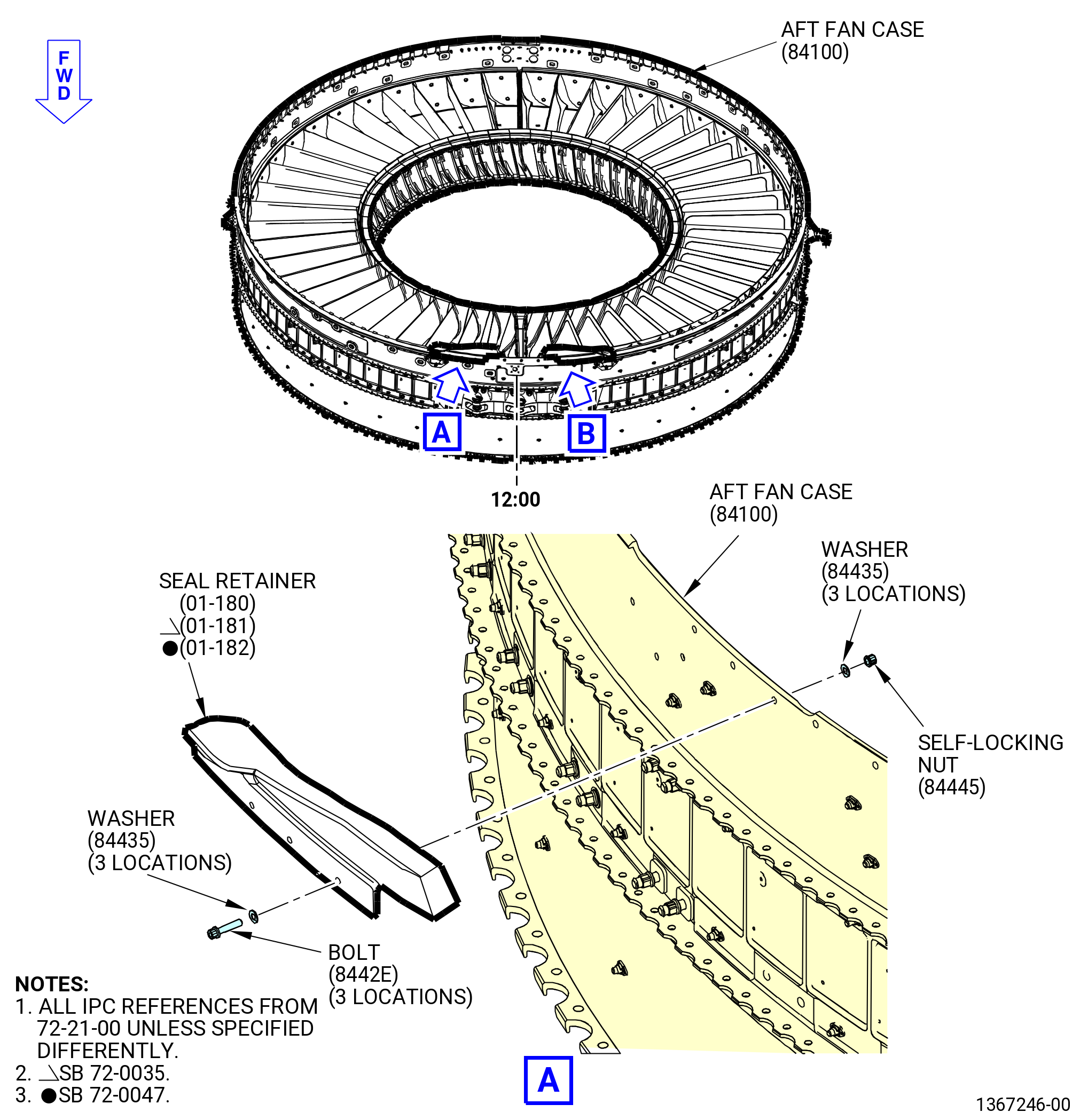
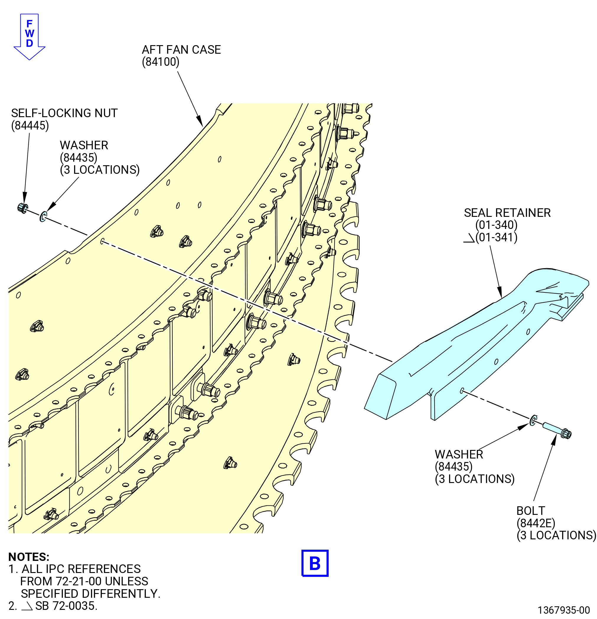
| G. | Remove the seal retainers (01-180) (SIN 84404) or (01-181) (SIN 84404) or (01-182) (SIN 84404), (01-340) (SIN 84504) or (01-341) (SIN 84504) from the aft fan case (01-035) (SIN 84100). Refer to Figure 507 and do as follows: |
| (1) | Remove the self-locking nuts (84445) and washers (84435) from the bolts (8442E) on the seal retainers. |
| (2) | Remove the bolts and washers from the seal retainers. |
| (3) | Remove the seal retainers from the aft fan case. |
| Subtask 72-21-00-040-100 |
| CAUTION: |
|
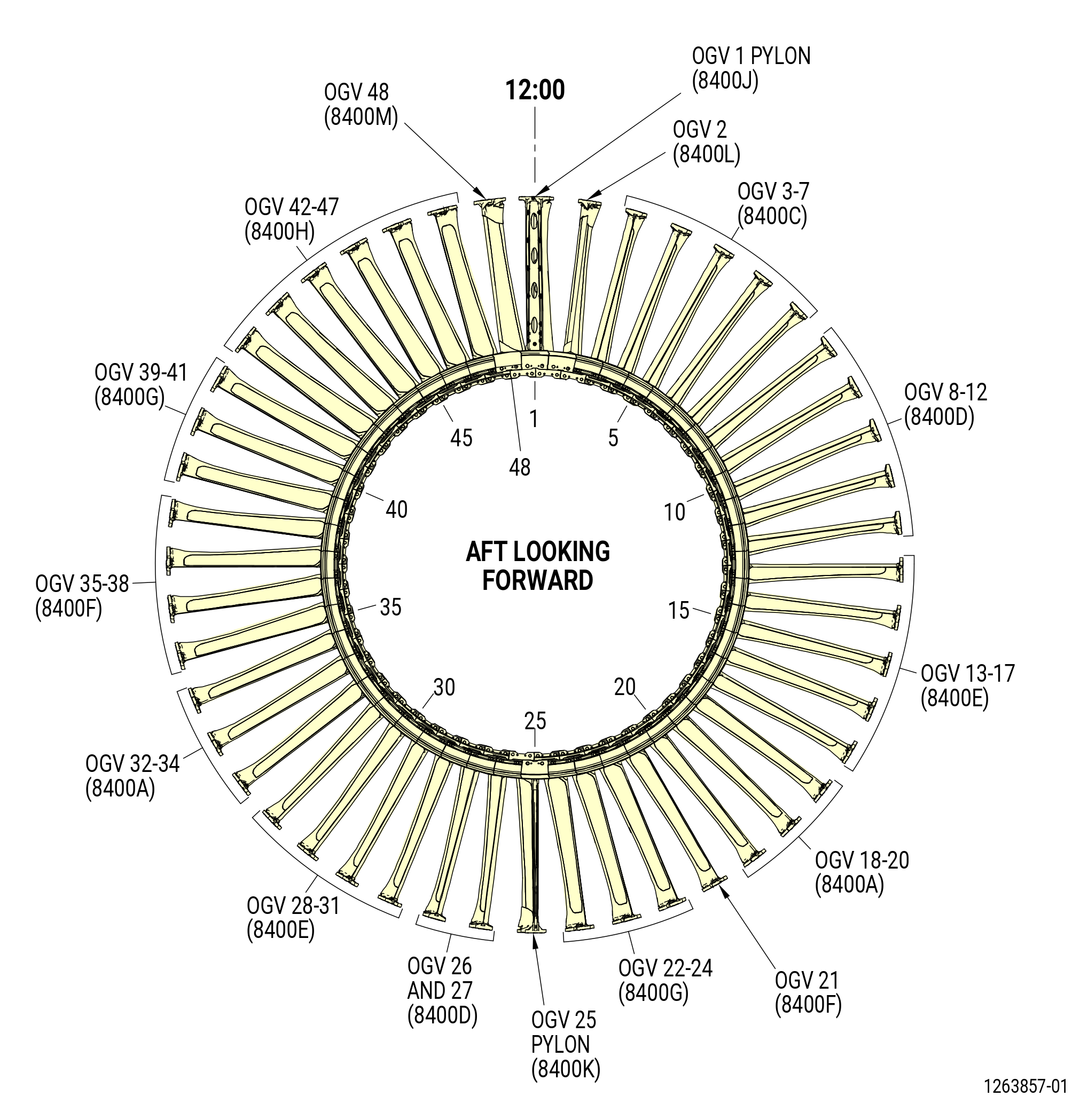
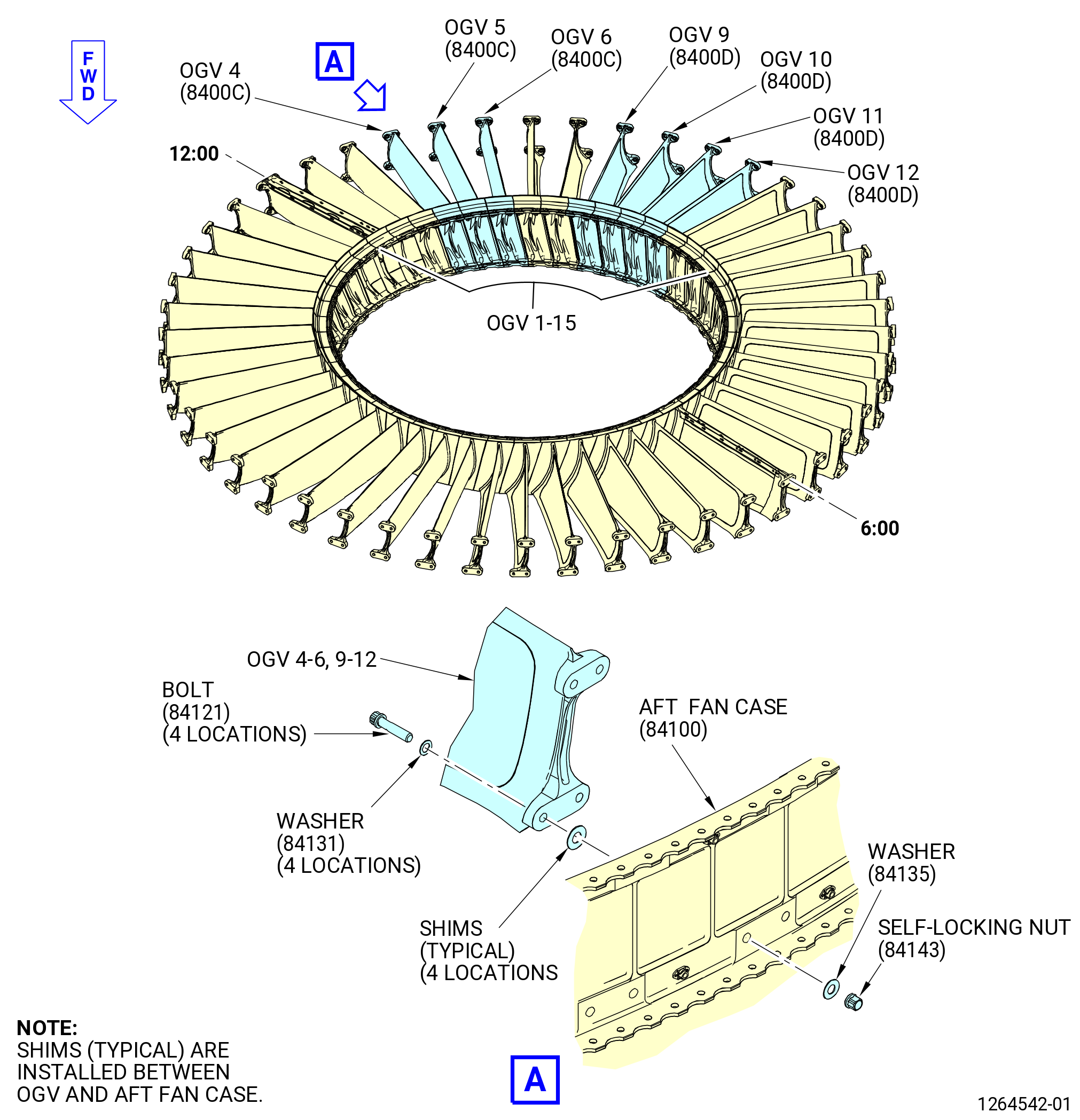
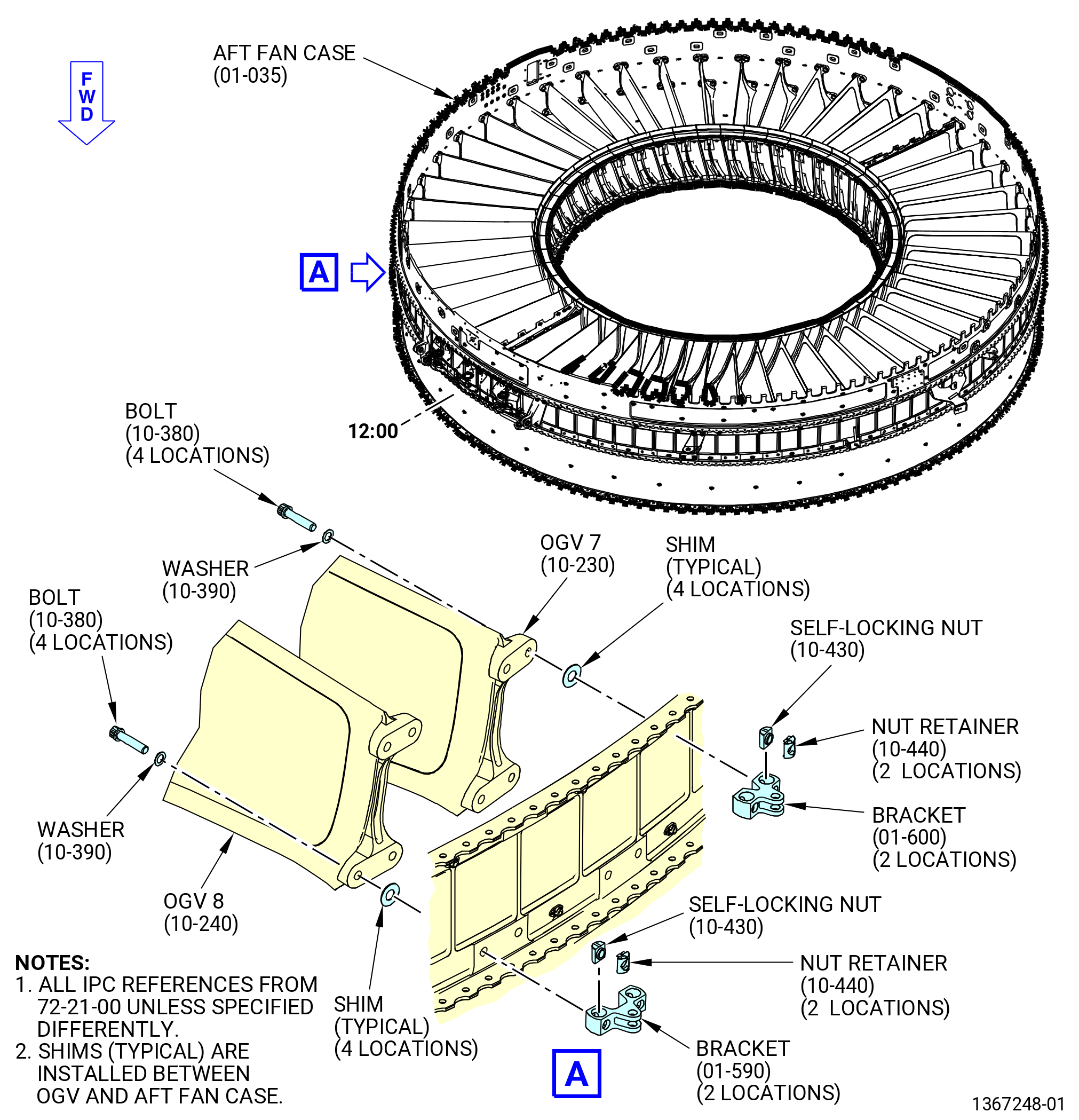
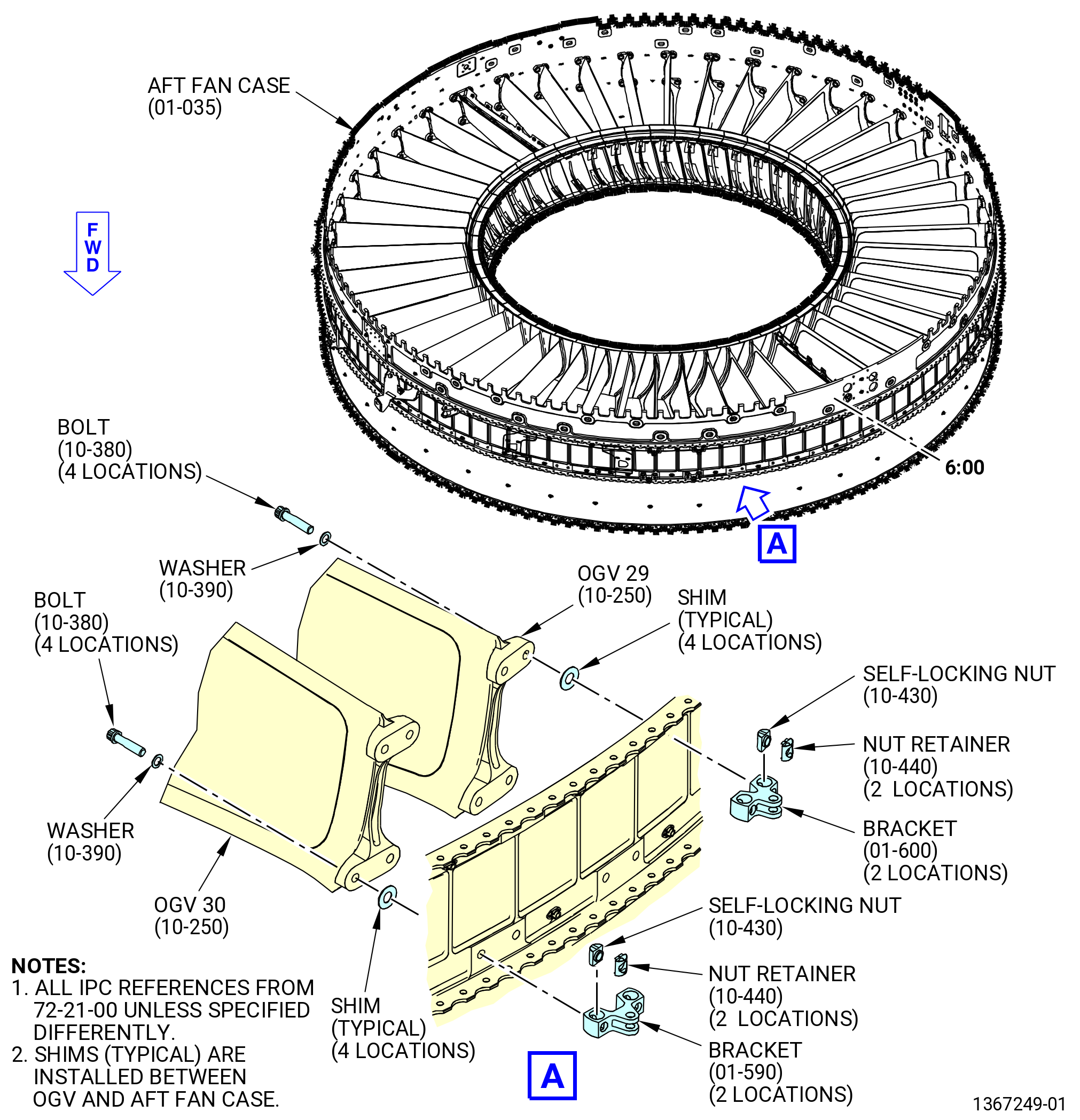
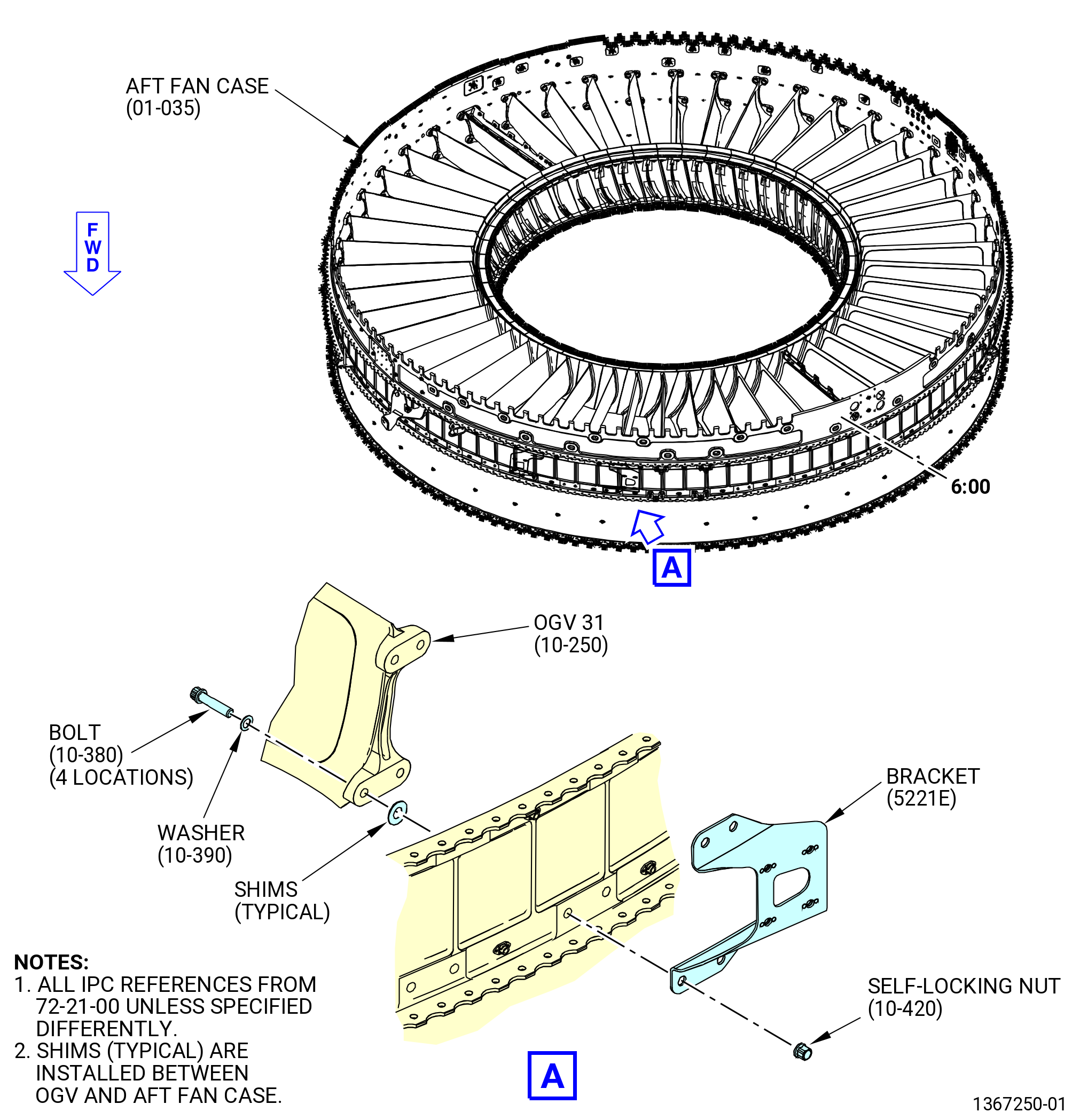
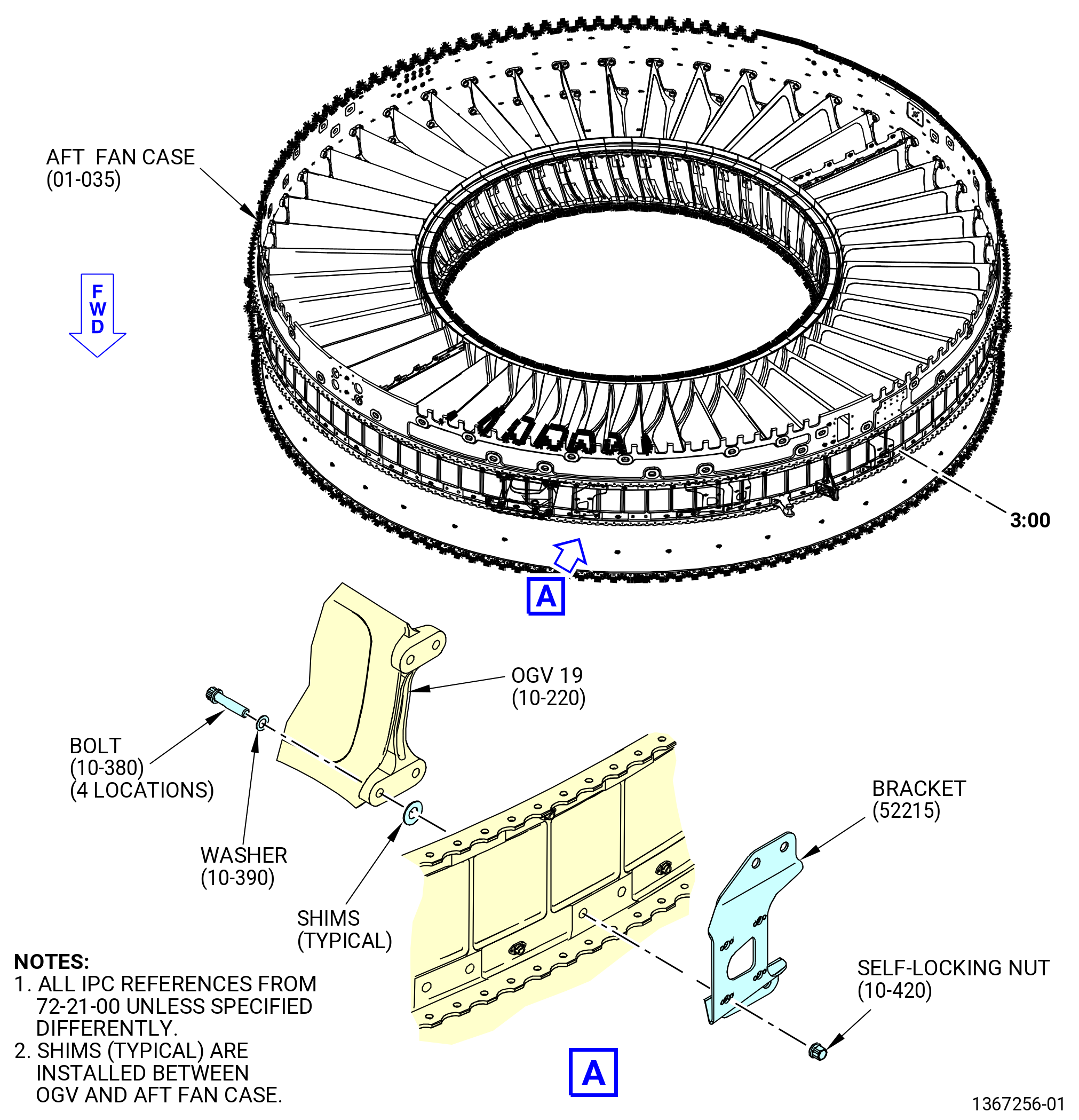
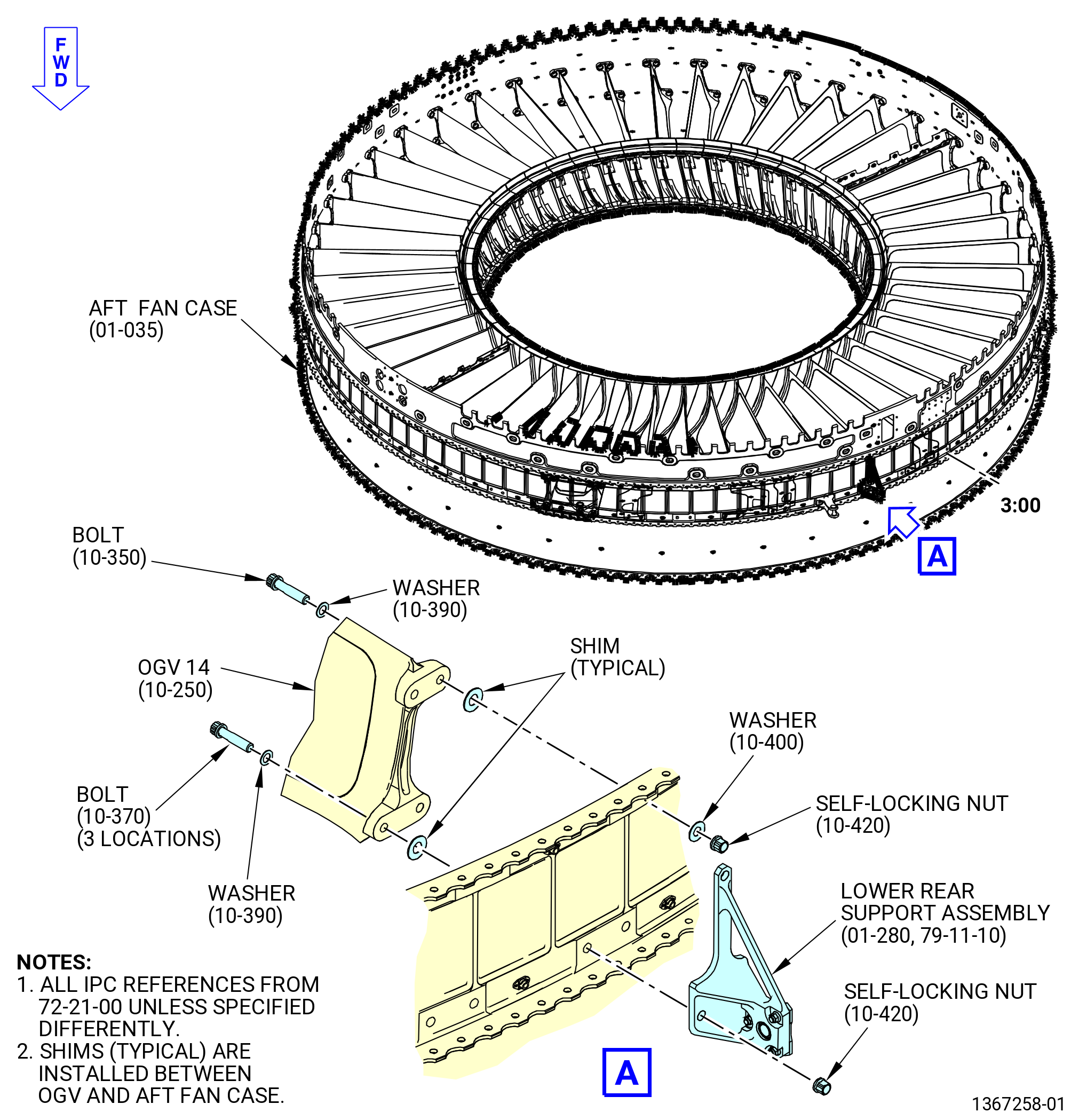
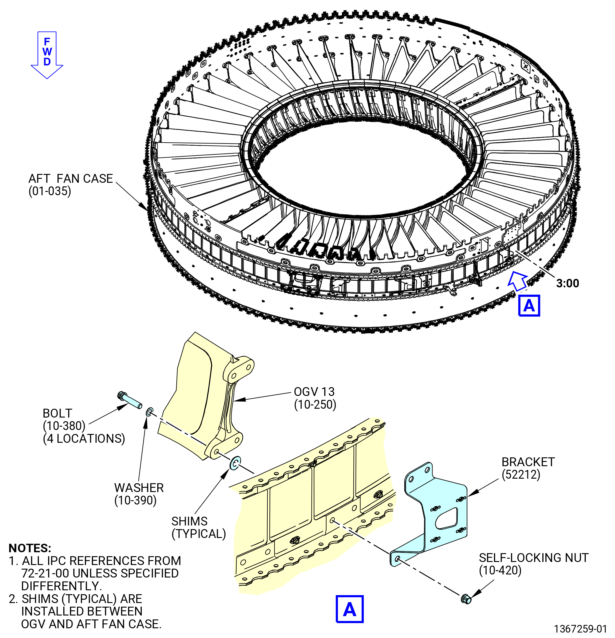
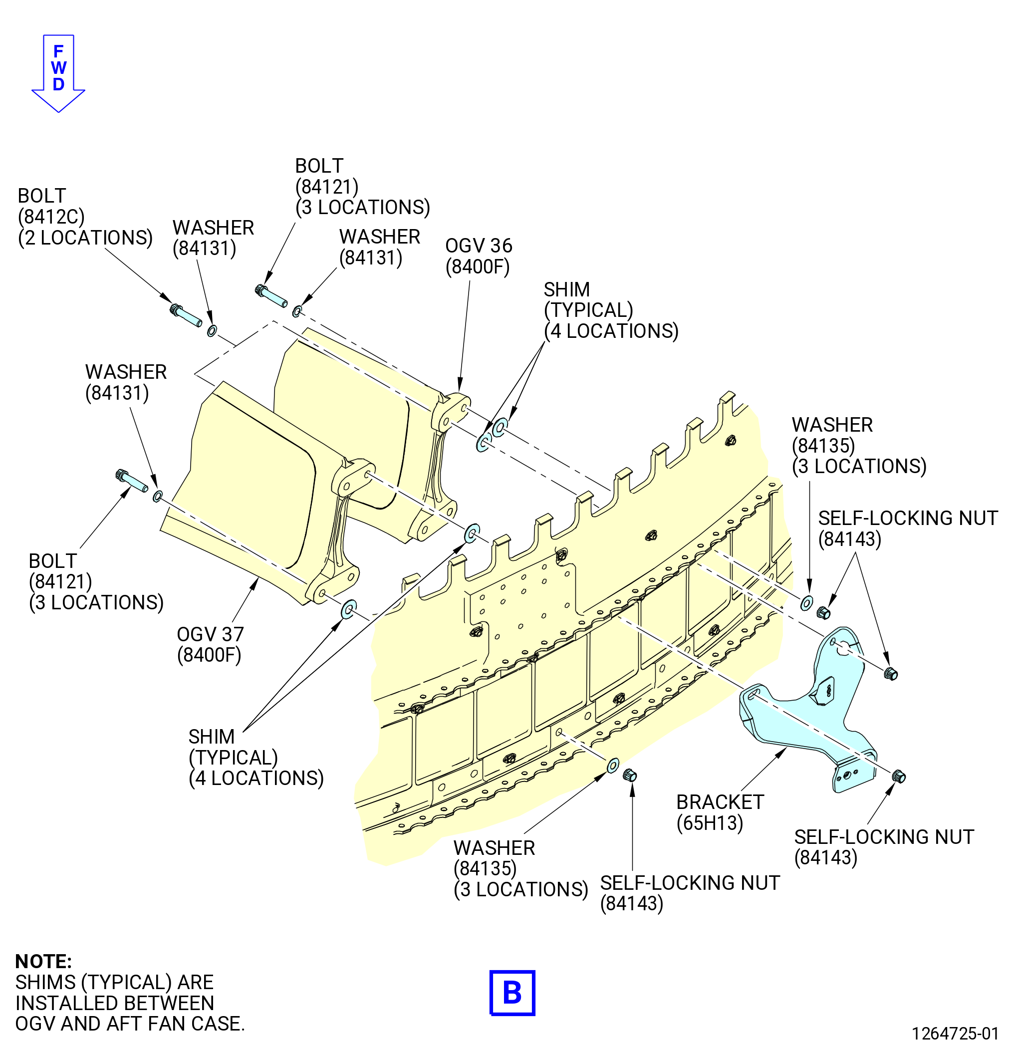
| H. | Remove the OGVs 3-47 from the aft fan case in the correct order the self-locking nuts, washers, bolts, shims, and brackets must be removed from the OGV locations as follows. Refer to Figure 508. |
| (1) | If necessary, install the 11C3237 restrain fixture on the OGVs. |
| (2) | Remove the self-locking nuts (84143), washers (84131, 84135), bolts (84121), and shims from OGVs 4-6, 9-12 (8400C, 8400D). |
| (3) | Remove the self-locking nuts (84144), nut retainers (84180), washers (84131), bolts (8412C), and brackets (98218, 98219) from OGVs 7 and 8 (8400C, 8400D). |
| (4) | Remove the self-locking nuts (84144), nut retainers (84180), washers (84131), shims, and brackets (98218, 98219) from OGVs 29 and 30 (8400E). |
| (5) | Remove the self-locking nuts (84143), washers (84131), bolts (8412C), shims, and bracket (5221E) from OGV 31 (8400E). |
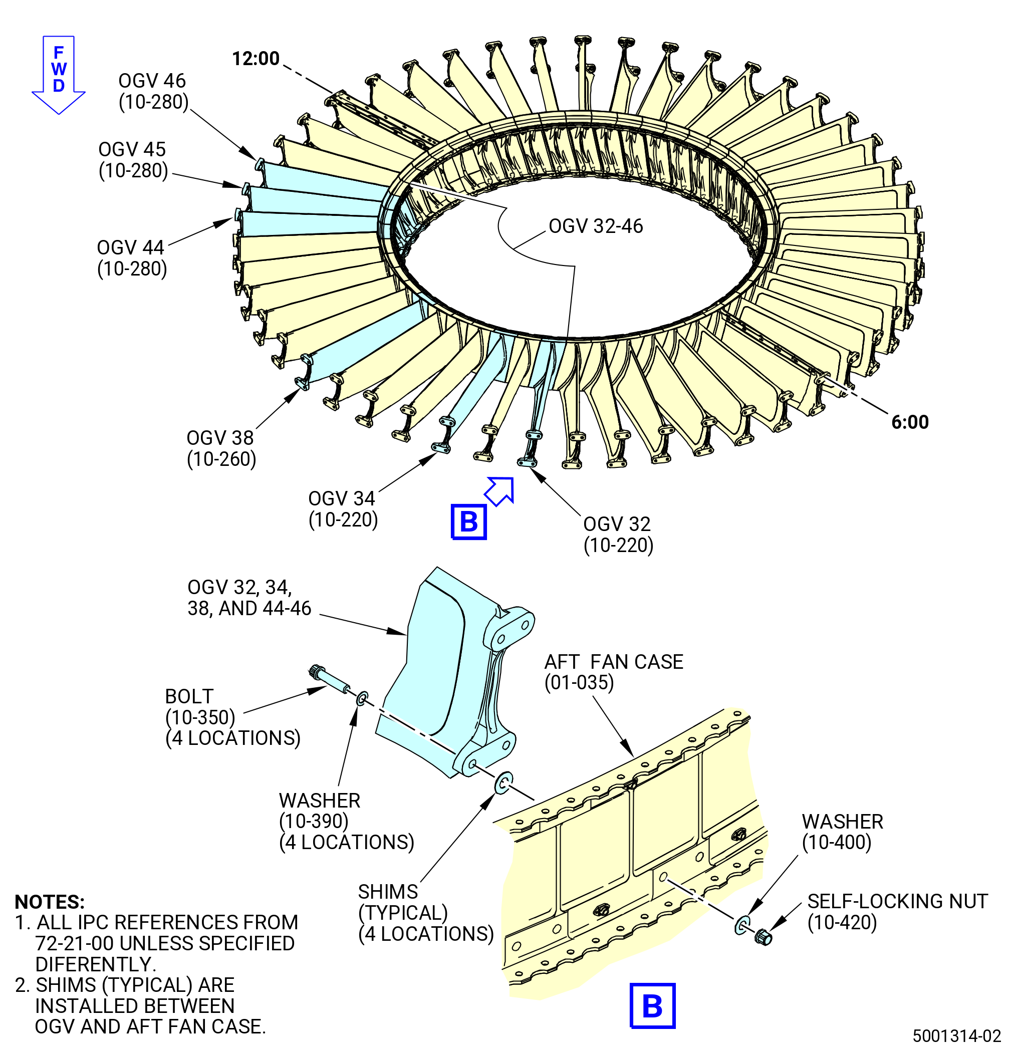
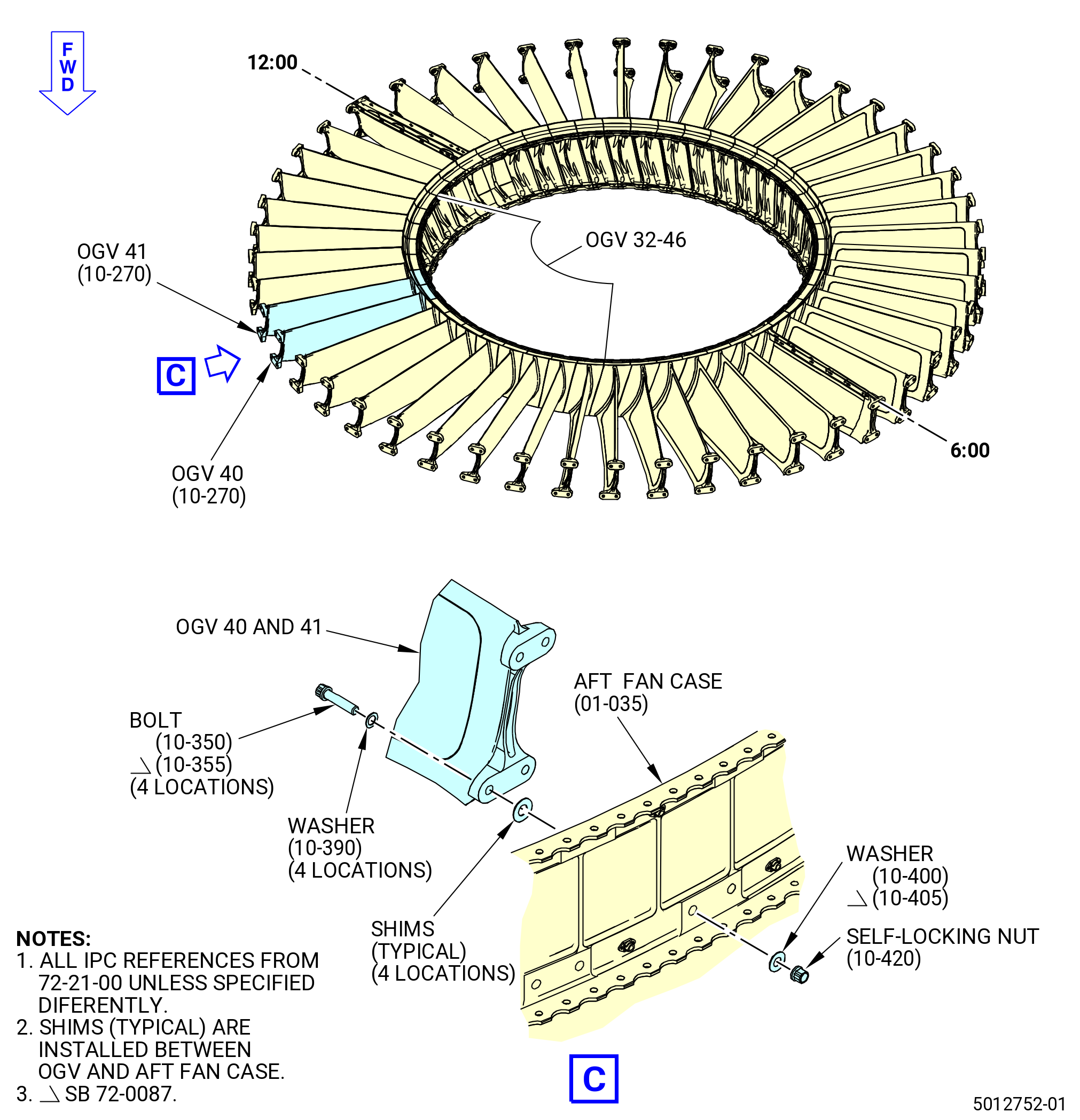
| (6) | Remove the self-locking nuts (84143), washers (84131), washers (10-400) (SIN 84135) or washers (10-405) (SIN 84136), bolts (10-350) (SIN 84121) or bolts (10-355) (SIN 8412D), and shims from OGVs 32, 34, 38, 40, 41, 44, 45, 46 (8400A, 8400F, 8400G, 8400H). |
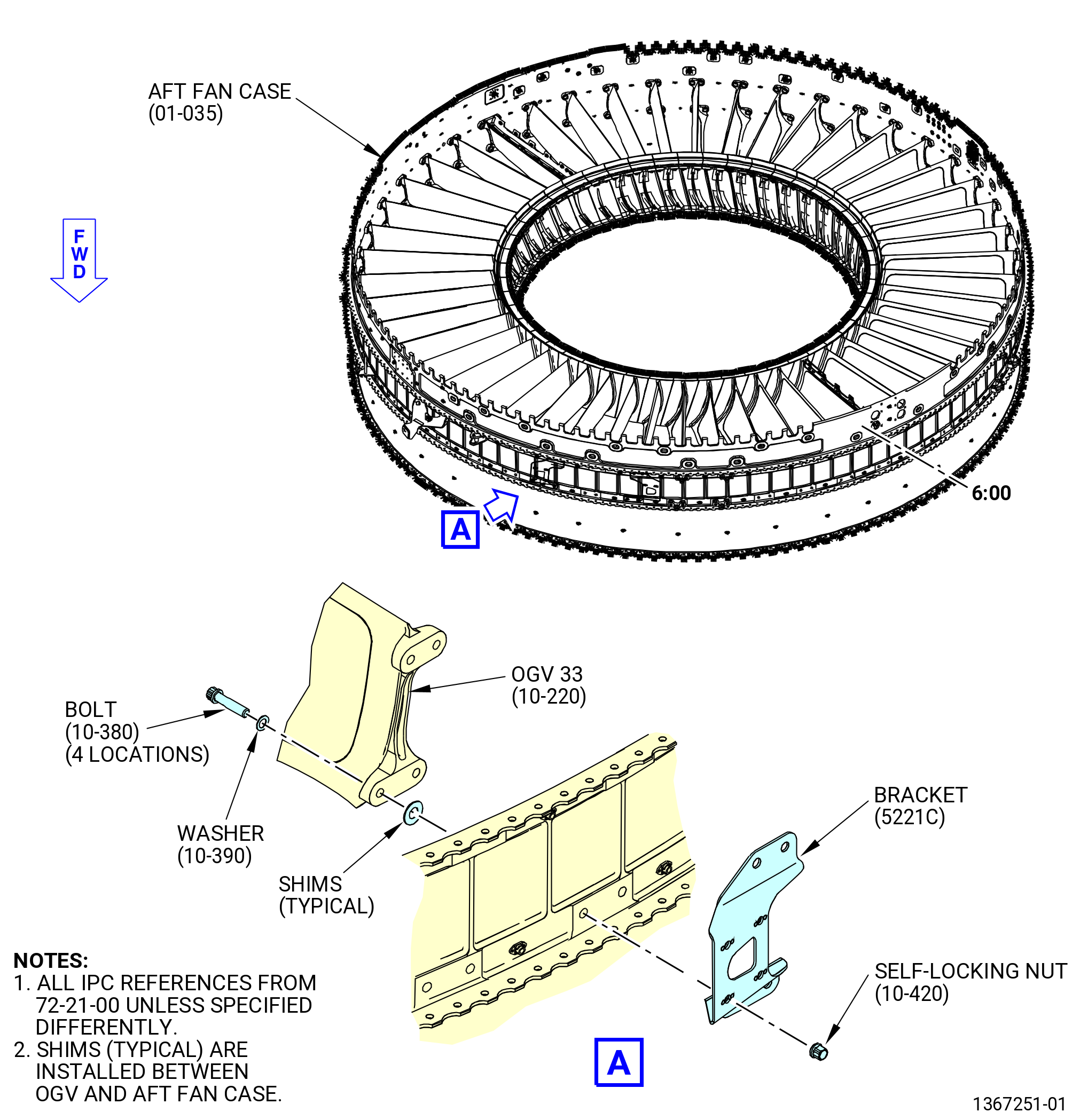
| (7) | Remove the self-locking nuts (84143), washers (84131), bolts (8412C), shims, bracket (5221C) from OGV 33 (8400A). |
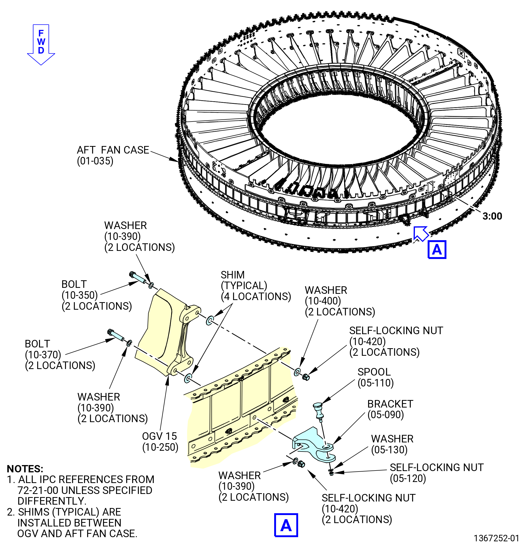
| (8) | Remove the self-locking nuts (84143), washers (84131, 84135), bolts (84121, 84129), shims, and bracket (98216) from OGV 15 (8400E). |
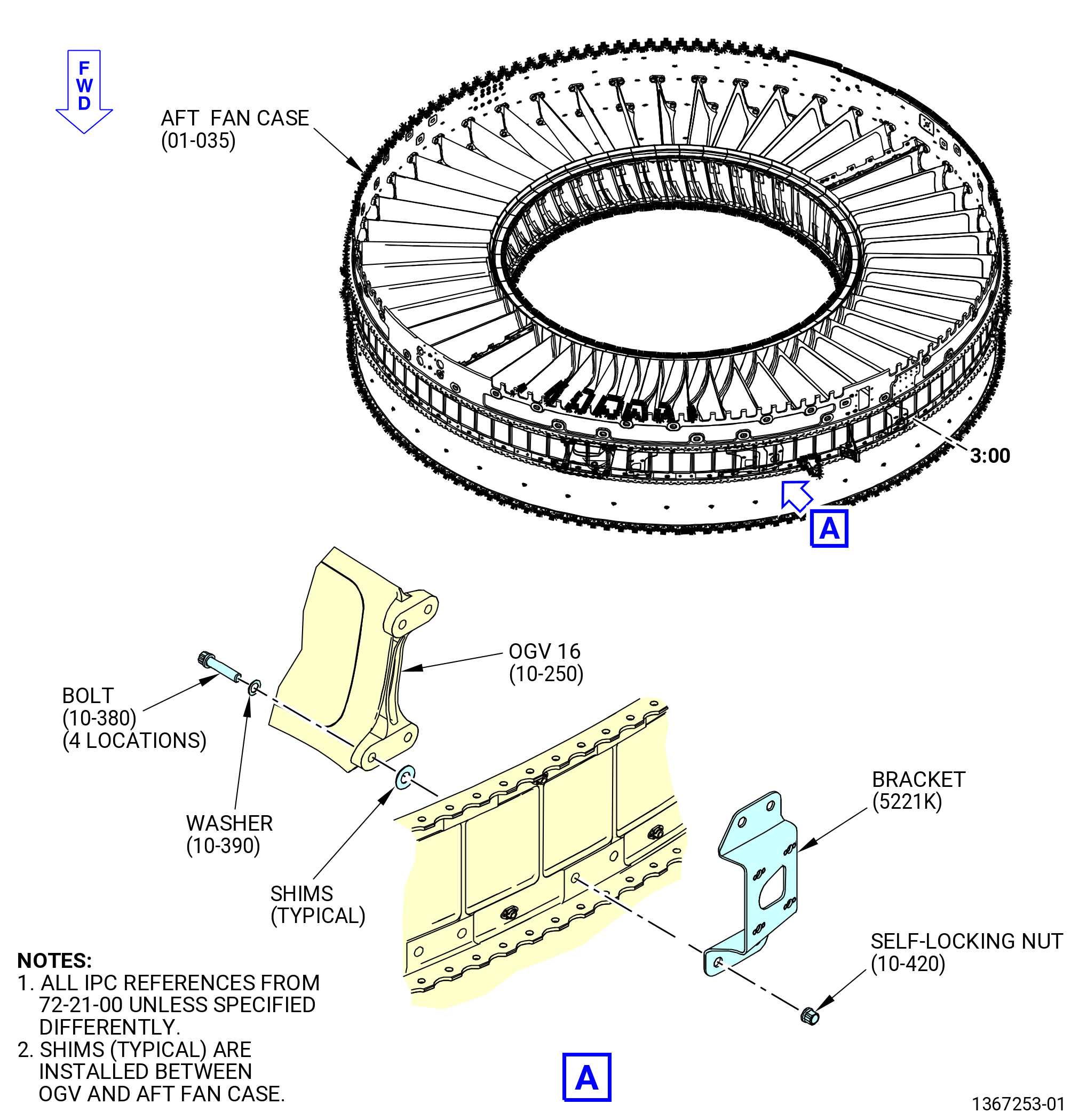
| (9) | Remove the self-locking nuts (84143), washers (84131), bolts (8412C), shims, bracket (5221K) from OGV 16 (8400E). |
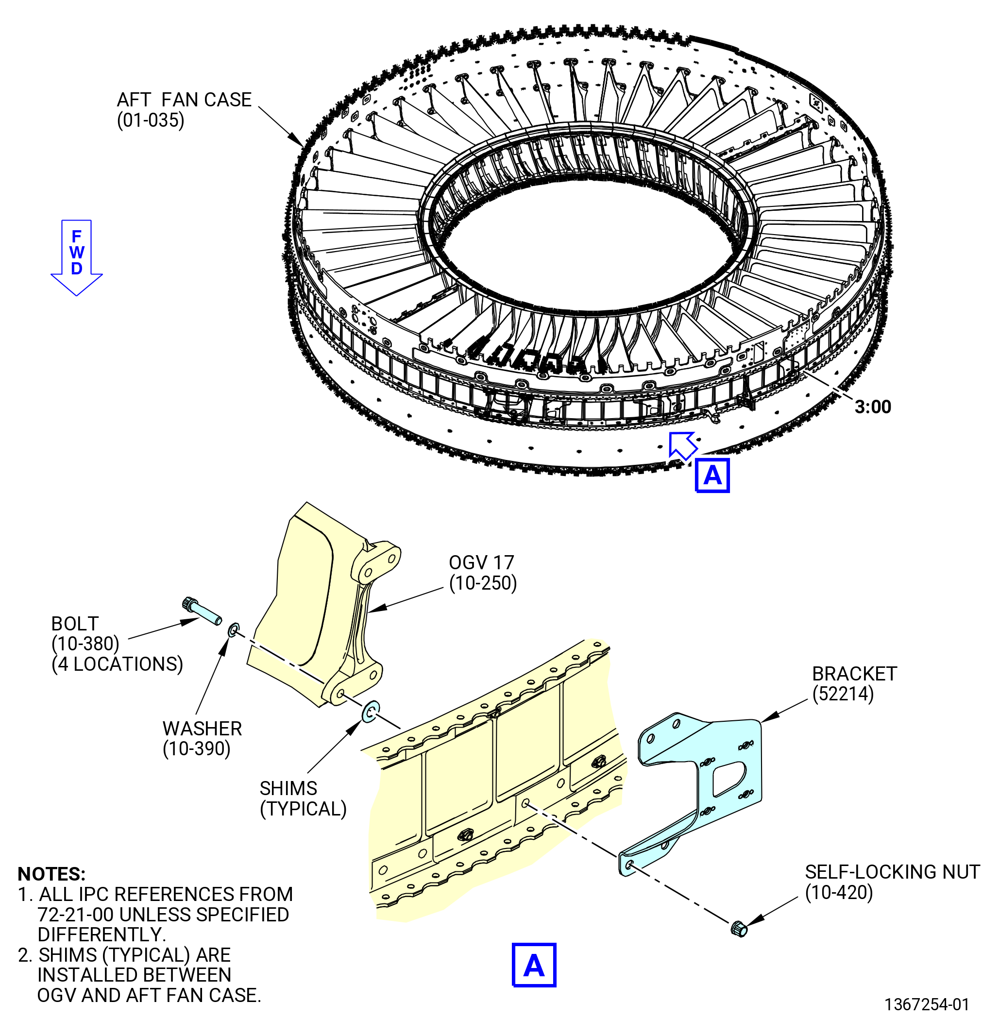
| (10) | Remove the self-locking nuts (84143), washers (84131), bolts (8412C), shims, bracket (52214) from OGV 17 (8400E). |
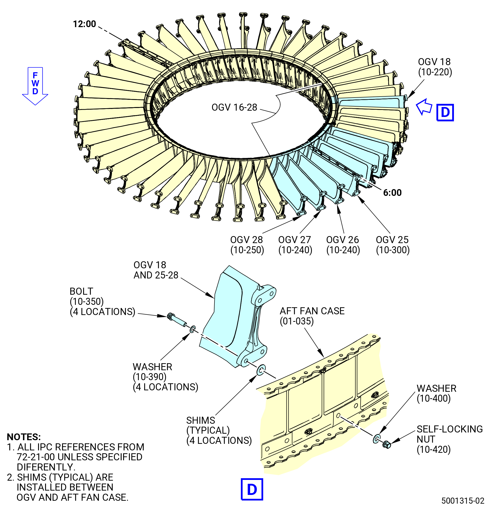
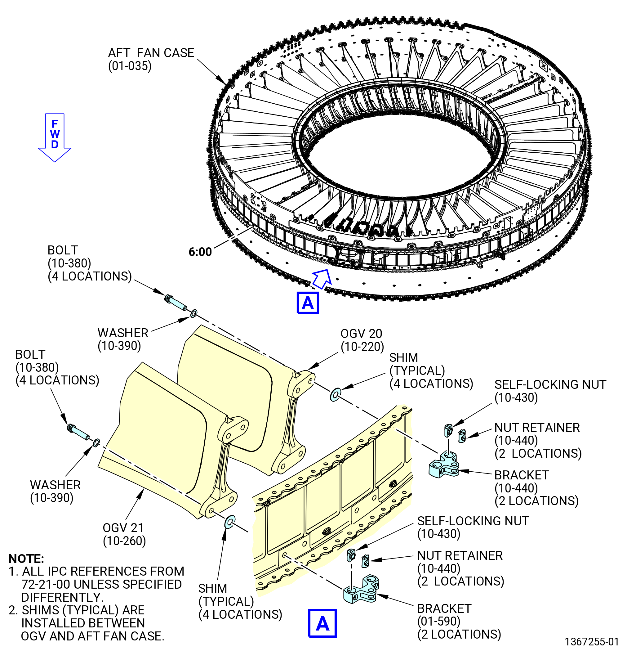
| (11) | Remove the self-locking nuts (84143), washers (84131), washers (10-400) (SIN 84135) or washers (10-405) (SIN 84136), bolts (10-350) (SIN 84121) or bolts (10-355) (SIN 8412D), and shims from OGV 18, 22, 23, 24, OGV pylon 25, 26, 27, 28 (8400A, 8400G, 8400K, 8400D, 8400E). |
| (12) | Remove the self-locking nuts (84144), nut retainers (84180), washers (84131), bolts (8412C), shims, and brackets (98218, 98219) from OGVs 20 and 21 (8400A, 8400F). |
| (13) | Remove the self-locking nuts (84143), washers (84131), bolts (8412C), shims, and bracket (52215) from OGV 19 (8400A). |
| (14) | Remove the self-locking nuts (84144), nut retainers (84180), washers (84131), bolts (8412C), shims, and brackets (98218, 98219) from OGVs 42 and 43. |
| (15) | Remove the self-locking nuts (84143), washers (84131, 84135), bolts (84121, 84129), shims, and support assembly (40010) from the OGV 14. |
| (16) | Remove the self-locking nuts (84143), washers (84131), bolts (8412C), shims, and bracket (52212) from OGV 13 (8400E). |
| (17) | Remove the self-locking nuts (84143), washers (84131, 84135), bolts (8412C, 84121), shims, and full authority digital engine control (FADEC) brackets (65H11) from OGV 39 (8400G). |
| (18) | Remove the self-locking nuts (84143), washers (84131, 84135), bolts (8412C, 84121), shims, and FADEC brackets (65H13) from OGVs 36 and 37 (8400F, 8400F). |
| (19) | Remove the self-locking nuts (84143), washers (84131, 84135), bolts (84121, 84129), shims, and bracket (98217) from OGV 35 (8400F). |
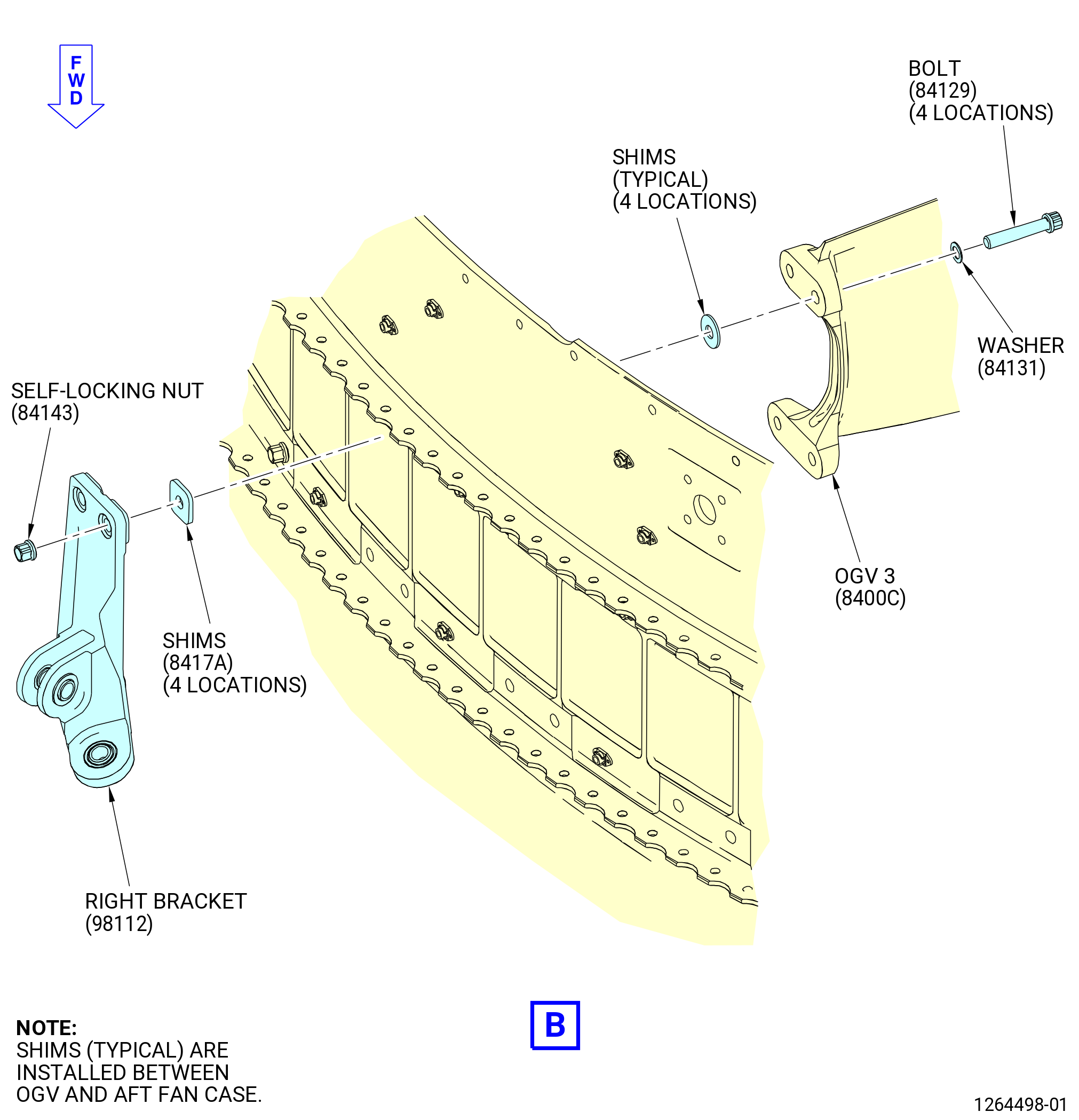
| (20) | Remove the self-locking nut (84143), washer (84131), bolts (84129) shims (8417A), and right cowl support bracket (98112) from OGV 3. |
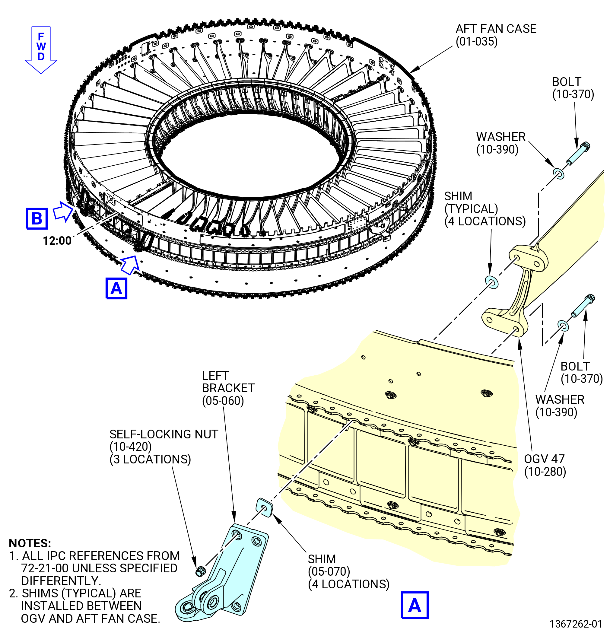
| (21) | Remove the self-locking nuts (84143), washers (84131), bolts (84129), shims (8417A), left bracket (98113) from OGV 47. |
| Subtask 72-21-00-040-101 |
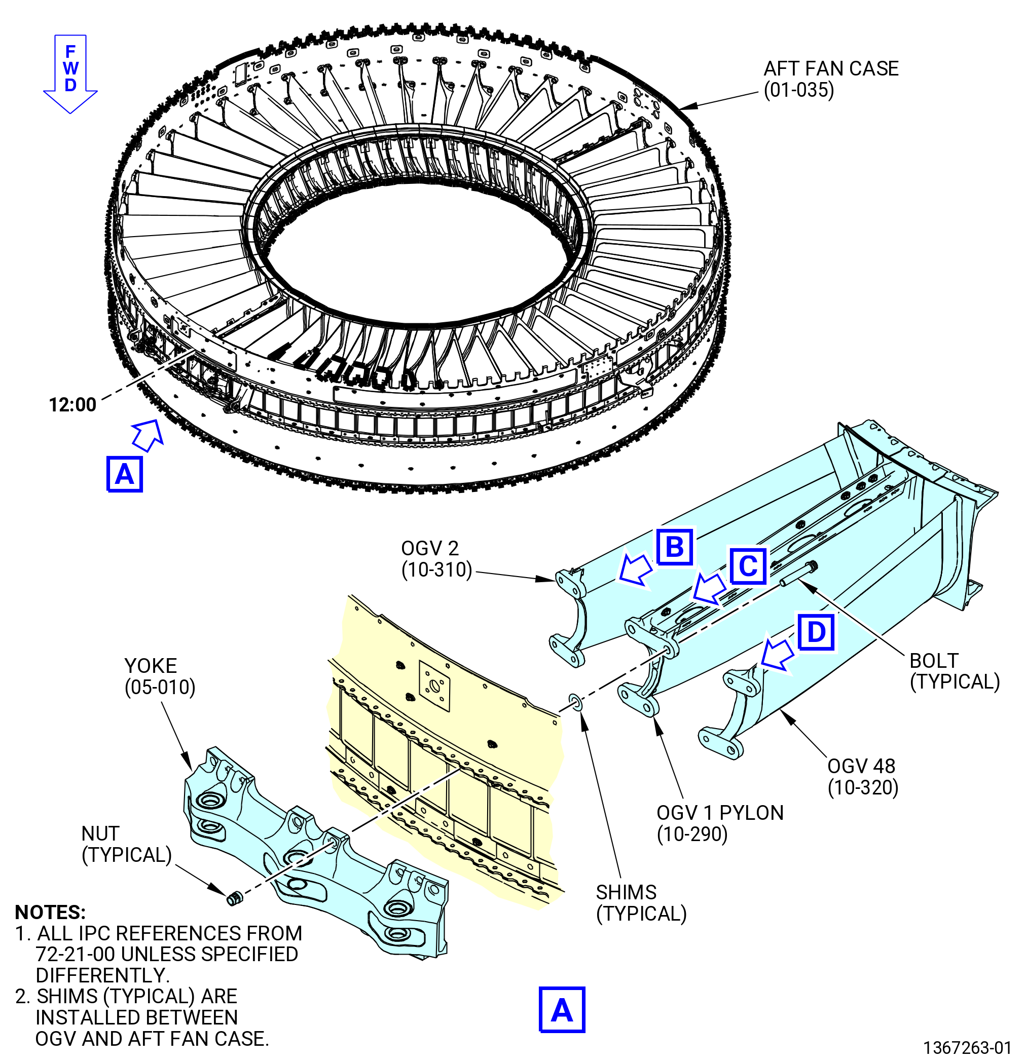
| I. | Remove the yoke (84803) from the aft fan case (84100) at OGV 1 pylon (8400J), OGV 2 (8400L), and OGV 48 (8400M) as follows. Refer to Figure 509. |
| WARNING: |
|
| (1) | Attach an overhead head hoist with a lift sling to the yoke. |
| (2) | Remove the self-locking nuts (84840, 84141) from the bolts (84123, 84124) on the yoke. |
| (3) | Remove the bolts from the yoke. |
| (4) | Remove the shims (8417C, 8417M, 8417K, 8417W), from the aft fan case and the yoke. |
| (5) | Remove the yoke from the aft fan case. |
| (6) | Remove the overhead hoist lift slings from the yoke. |
| Subtask 72-21-00-040-111 |
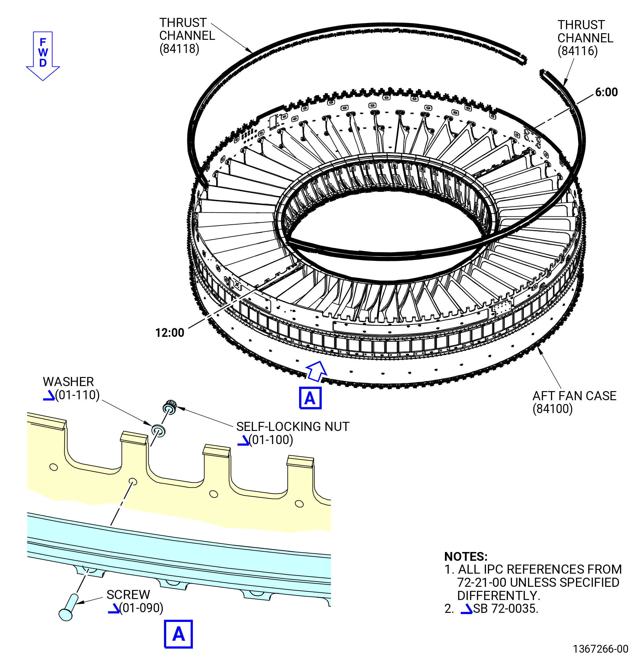
| J. | Remove the lower thrust reverser channel (thrust channel) (01-060) (SIN 84116) and thrust reverser lower channel (thrust channel) (01-070) (SIN 84118) from the aft fan case (01-035) (SIN 84100). Refer to Figure 510 and do as follows: |
| (1) | Remove the self-locking nuts (01-100) (SIN 84440) and the washers (01-110) (SIN 84534) on the inboard side of the aft fan case. |
| (2) | Remove the screws (01-090) (SIN 84424) and the trust channel from the outboard side of the aft fan case. |
| Subtask 72-21-00-040-112 |
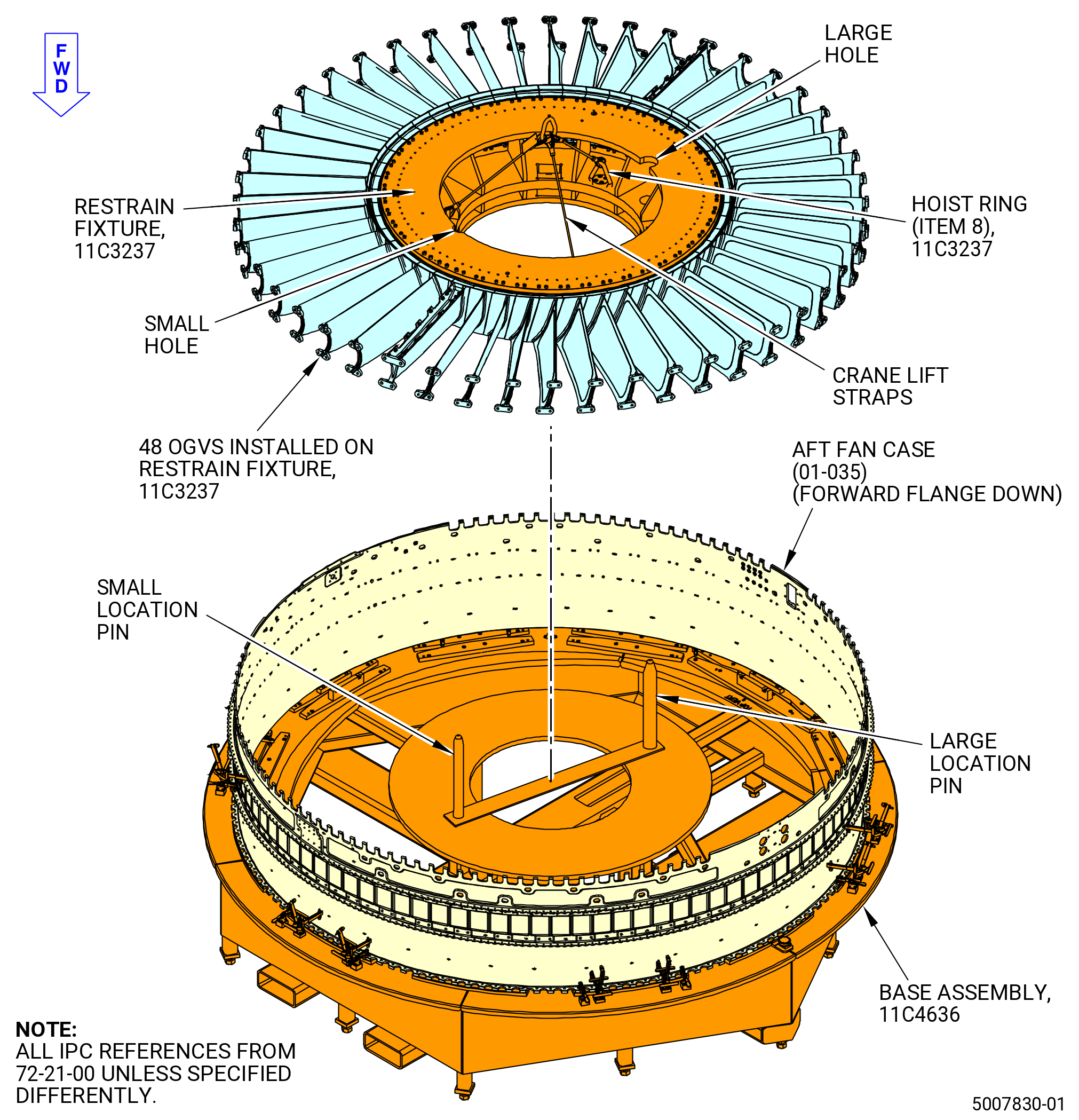
| K. | Remove the OGVs 1-48 (10-220) (SIN 8400A), (10-230) (SIN 8400C), (10-240) (SIN 8400D), (10-250) (SIN 8400E), (10-260) (SIN 8400F), (10-270) (SIN 8400G), (10-280) (SIN 8400H), (10-290) (SIN 8400J), (10-300) (SIN 8400K), (10-310) (SIN 8400L) and (10-320) (SIN 8400M) from the aft fan case (01-035) (SIN 84100). Refer to Figure 511 and do as follows: |
| WARNING: |
|
| (1) | Lift 11C3237 restrain fixture and the OGVs 1-48 from the aft fan case. |
| (2) | Align the bushings on the 11C3237 restrain fixture with the pins on a floor mounted storage stand as the 11C3237 restrain fixture is lowered on the support stand. |
| (3) | Attach the 11C3237 restrain fixture to the floor mounted support stand. |
| (4) | Remove the overhead hoist lift slings from the 11C3237 restrain fixture. |
| (5) | Remove the OGVs 1-48 from the 11C3237 restrain fixture as follows: |
| (a) | Support the OGV and remove the capscrews (item 15) from the aft inner mounting flange of the inner platform at 88 locations. |
| (b) | Support the OGV and remove the capscrews (item 10) from the aft inner mounting flange of the inner platform at eight locations. |
| (c) | Carefully lower the outer end of the OGV and lift the inner platform from the straight pin (item 13) and the locator pin (item 7). |
| (6) | Carefully keep the OGVs in storage and record the position where the OGV was removed. |
| (7) | Put the 11C3237 restrain fixture in its storage location and remove the lift straps from hoist and fixture. |