| GENX-1B ENGINE MANUAL | Dated: 05/08/2024 | |
| EM 72-00-01 , INSTALLATION 001 | ||
| FAN STATOR MODULE ASSEMBLY - INSTALLATION 001 - CONFIGURATION 01 | ||
| GENX-1B ENGINE MANUAL | Dated: 05/08/2024 | |
| EM 72-00-01 , INSTALLATION 001 | ||
| FAN STATOR MODULE ASSEMBLY - INSTALLATION 001 - CONFIGURATION 01 | ||
| * * * FOR 1B/P/G03.1B/P/G04.1B/P1/G01 |
| TASK 72-00-01-420-801 |
| 1 . | General. |
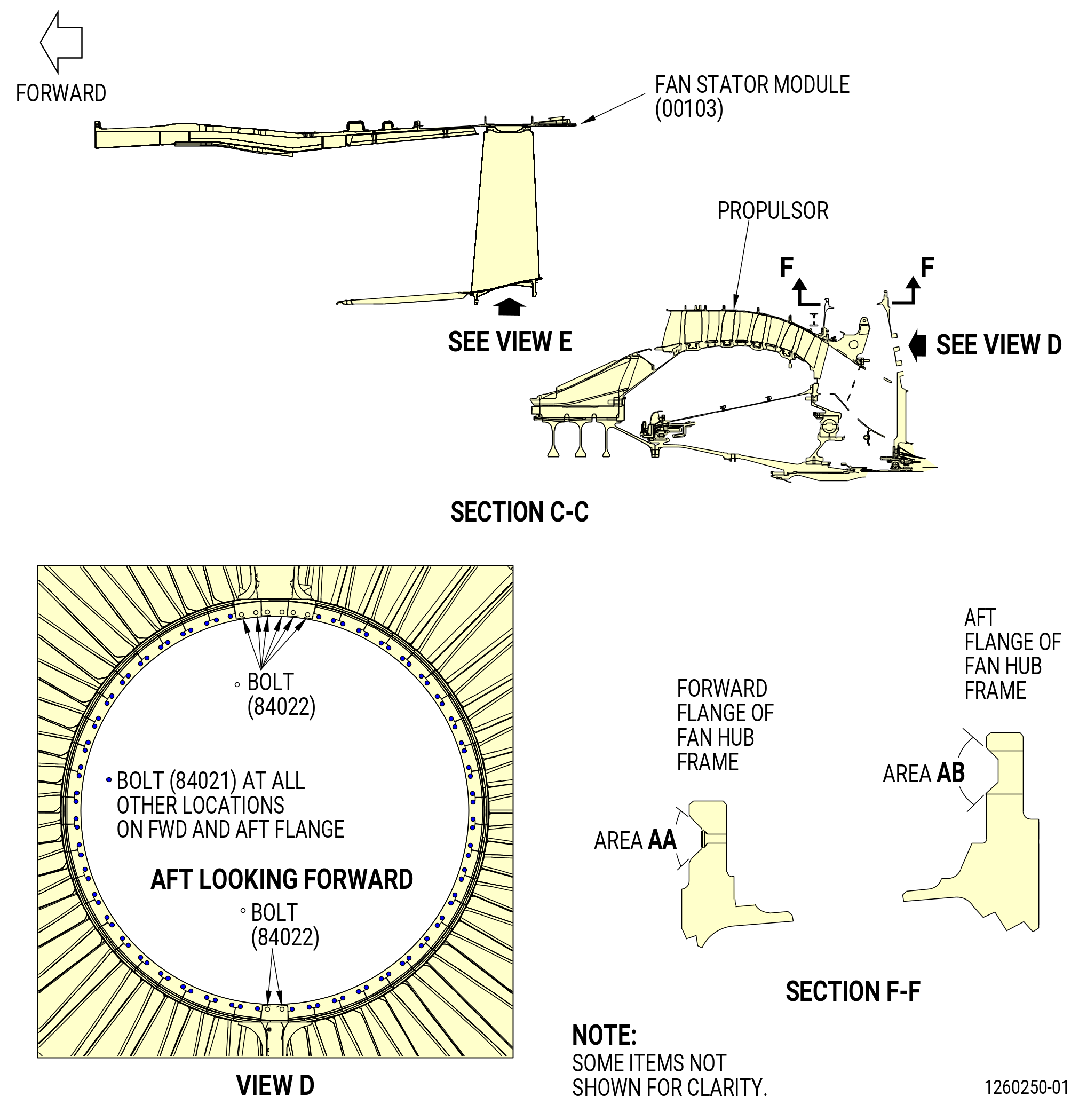
| A. | This procedure gives instructions to install the fan stator module assembly (fan stator module) (00103) to the propulsor module. Refer to Figure 402. |
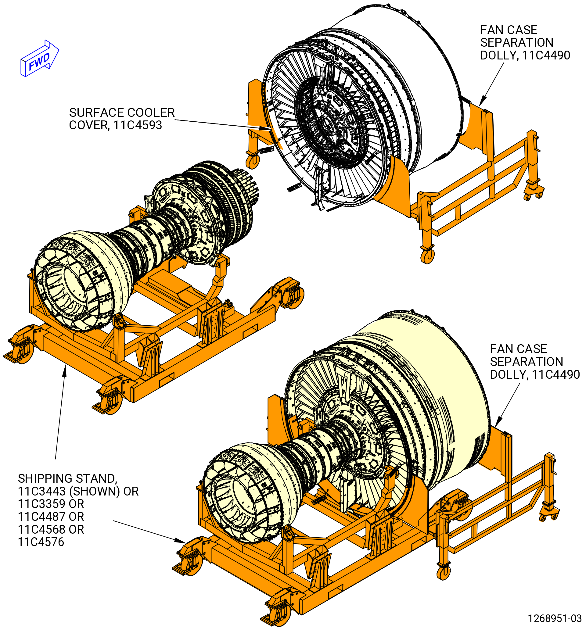
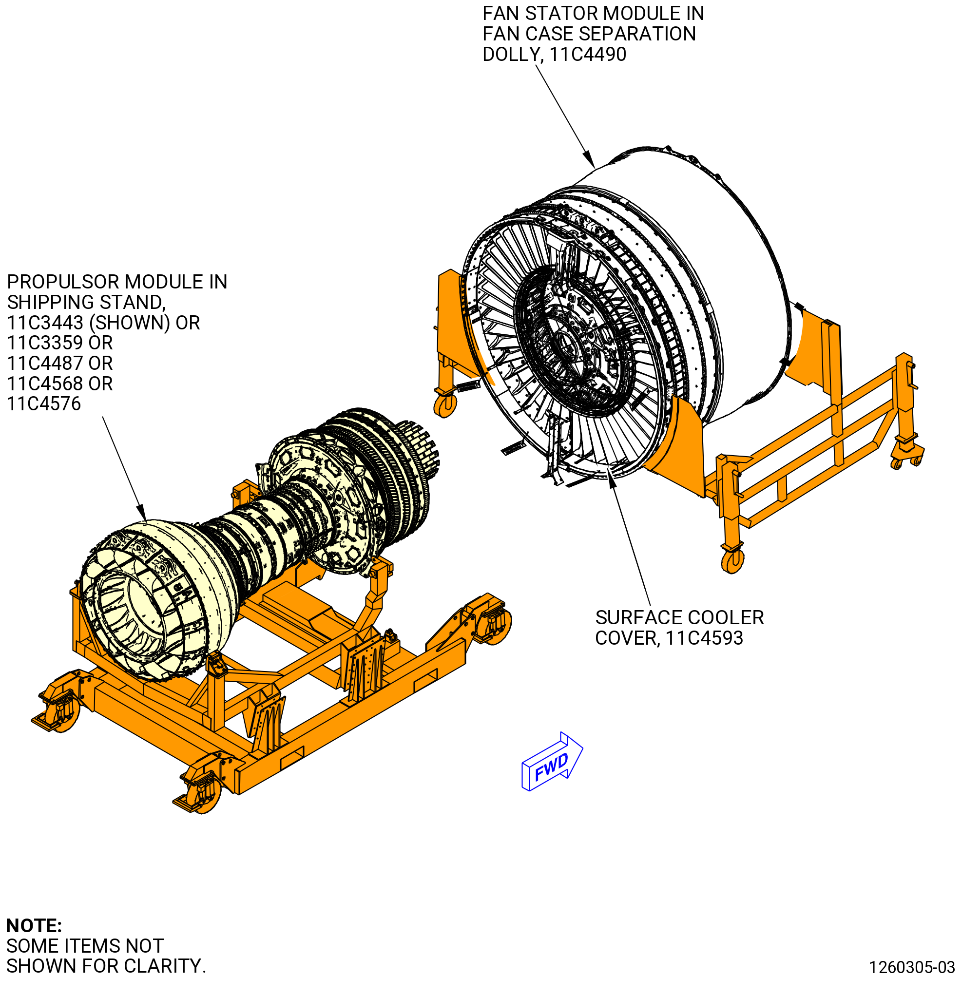
| B. | This procedure starts with the fan stator module in the 11C4490 fan case separation dolly in the horizontal position and the propulsor module in the 11C3443 shipping stand or 11C3359 shipping stand or 11C4487 shipping stand or 11C4568 shipping stand or 11C4576 shipping stand. As an alternative, you can install the propulsor module in the 11C3281G01 turbine rear frame (TRF) pedestals and 11C3281G02 fan hub frame (FHF) pedestals . Refer to TASK 72-00-00-800-803 (72-00-00, SPECIAL PROCEDURE 003) . |
| C. | Make sure that the personnel read the procedure and know the step-by-step instructions and special tool usage before they install the fan stator module. |
| D. | Make sure that there is no foreign material in the engine or on the engine parts. |
| E. | Make sure that all parts are serviceable before you install them. |
| F. | The torque values given in this procedure are the actual torque to apply to the fastener. If a torque multiplier is used, do the necessary calculations to find the specified torque for the value that appears on the scale or dial of the torque wrench. Refer to TASK 70-51-00-400-004 (TIGHTENING PRACTICES AND TORQUE VALUES) . |
| 2 . | Tools, Equipment, and Materials. |
| NOTE: |
|
| A. | Tools and Equipment. |
| (1) | Special Tools. |
| (2) | Standard Tools and Equipment. None. |
|
| (3) | Locally Manufactured Tools. None. |
| B. | Consumable Materials. |
|
| C. | Referenced Procedures. |
|
| D. | Expendable Parts. |
|
| 3 . | Procedure. |
| Subtask 72-00-01-420-001 |
| A. | Prepare the fan stator module (00103). Refer to Figure 403 and as follows: |
| (1) | If the fan stator module is installed on the 11C3004 shipping stand, transfer it to the 11C4490 fan case separation dolly as follows: |
| (a) | Before the fan stator module removal, make sure that the 11C3004 shipping stand is in the pallet vertical (engine horizontal) orientation. |
| (b) | If necessary, remove the safety pins for the shipping braces to be removed from the center support and main base. Return the shipping braces to their storage location on the 11C3004 shipping stand. |
| (c) | If installed, remove the fan stator module cover. |
| (d) | Shift the “C” valve handle to the “UP” position to fully raise the center support. Once the center support is fully raised, shift the “C” valve to the “OFF” position. |
| (e) | Remove the safety pins to disconnect the four turnbuckle braces between the OGV support ring and the center support. |
| (f) | Remove the locking pin from the fan mounting plate and rotate the fan stator module to the designated “LOAD” position. Install the locking pin again. |
| (g) | Identify the two cut-outs in the fan mounting ring at the 3:00 o'clock and 9 o'clock positions. The 11C4490 fan case separation dolly will be installed at these locations. Remove any fasteners between the fan case and the fan mounting ring with the span of these cut-outs only. |
| (h) | Slide the 11C4490 fan case separation dolly up to the fan case so that their brackets with holes are on the AFT side of the fan case flange. |
| (i) | Adjust the jacklegs on the 11C4490 fan case separation dolly as necessary to achieve hole alignment. |
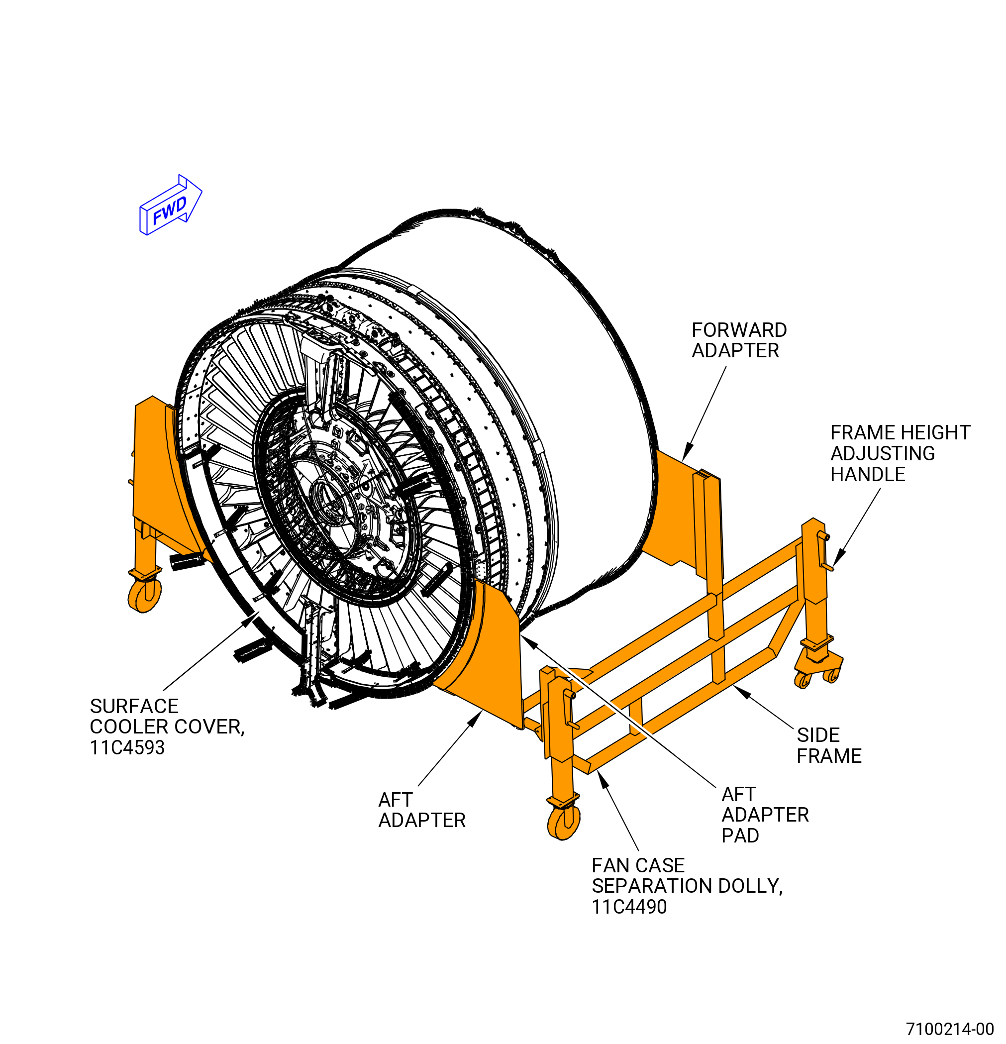
| (j) | Attach the 11C4490 fan case separation dolly to the fan stator case. Refer to Figure 401 and as follows: |
| 1 | Use the jacking caster legs of the 11C4490 fan case separation dolly to align the support bracket of the 11C4490 fan case separation dolly with the fan stator case flanges. |
| 2 | Attach the left and right support brackets to the forward and aft flanges of the fan stator module. |
| (k) | Make sure that the 11C4490 fan case separation dolly supports the weight of the fan stator module. |
| (l) | Remove the fasteners that hold the fan stator module to the fan mounting ring. |
| (m) | Pull the fan stator module forward or push the 11C3004 shipping stand aft to slowly separate the fan stator module from the 11C3004 shipping stand. |
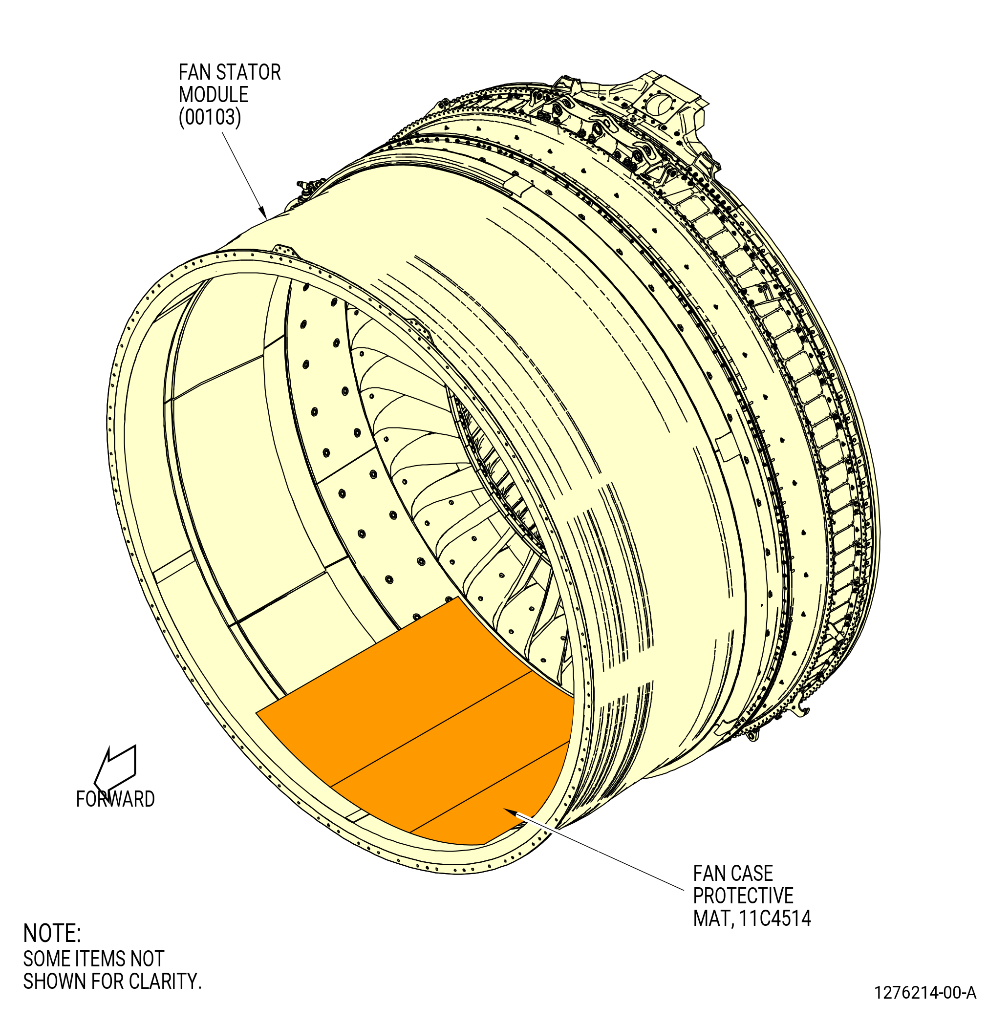
| (2) | Put an 11C4514 fan case protective mat in the lower fan case area at the 6:00 o'clock location to prevent damage to the inside surfaces of the fan stator module. Refer to Figure 404. |
| CAUTION: |
|
| (3) | Install the 11C3331 protectors, if they are not installed. This will protect the forward edge of the acoustic panels. Refer to Figure 403. |
| WARNING: |
|
| (4) | Clean the forward and aft flanges of the fan hub module, and the fan stator module, with C04-035 isopropyl alcohol. Refer to Figure 405. |
| (5) | Remove any tape that is around the fan hub module. |
| (6) | Make sure that all nut plates are installed on the fan hub module. |
| (7) | If not installed, install the 11C4593 surface cooler cover. |
| Subtask 72-00-01-420-002 |
| B. | Install the fan stator module (00103) to the propulsor as follows: |
| (1) | Make sure that the fan stator module and the propulsor are level. Lower the workstation and/or adjust the fan case dolly to align the fan stator module with the propulsor. |
| (2) | Apply C03-079 primer or C03-085 primer to the forward side only of two fan hub module flange grooves in areas AA and AB around the circumference of the fan hub module. Refer to Figure 405. |
| (3) | Deleted. |
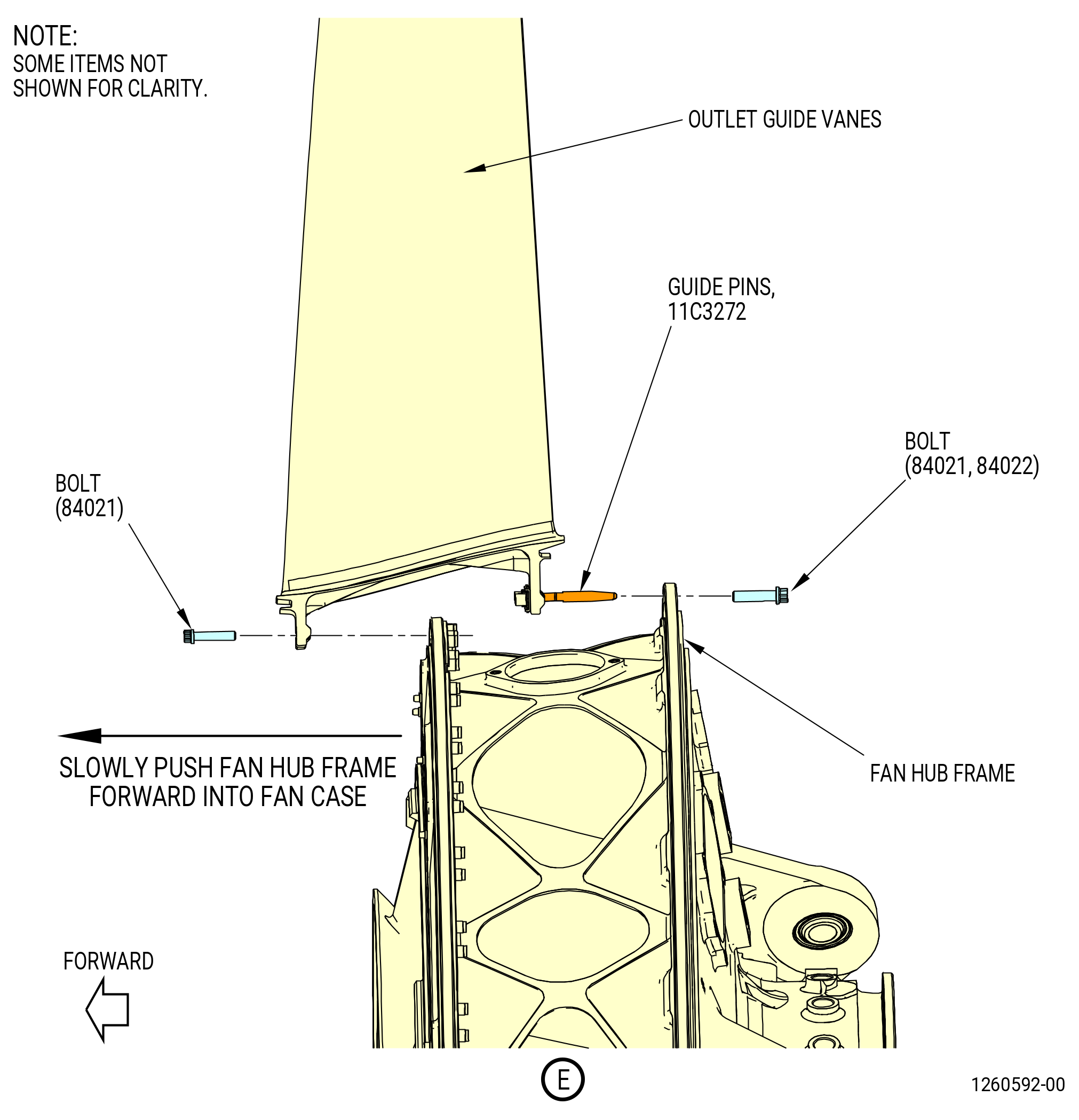
| (4) | Slowly push the propulsor into the fan stator module as follows: |
| (a) | Use visual indicators to make sure that the propulsor and fan stator module are in close alignment. Make adjustments as necessary to attach the two modules correctly. |
| (b) | Make sure that the OGV boltholes are aligned with the boltholes in the aft flange of the fan hub frame. |
| (c) | Make sure that all tools or foreign objects are removed from inside the fan case. Make sure that the drain lines at the 12:00 o'clock position are clear of the mating flanges. |
| (d) | Push the modules together until the bolts (30-070 , 72-00-00) (SIN 84021) can be started into the fan hub frame flanges by hand a minimum of 0.25 inch (6.4 mm) before wrenches are used. |
| (e) | Temporarily install several bolts (30-070 , 72-00-00) (SIN 84021) to hold the flanges together. They will be removed and install again in a later step. |
| Subtask 72-00-01-420-003 |
| WARNING: |
|
| (5) | Lubricate the threads of 192 bolts ((30-070 , 72-00-00) (SIN 84021), (30-060 , 72-00-00) (SIN 84022)) with C02-058 graphite. |
| NOTE: |
|
| WARNING: |
|
| (6) | Apply C03-079 primer or C03-085 primer to all surfaces of the bolt assemblies ((30-070 , 72-00-00) (SIN 84021), (30-060 , 72-00-00) (SIN 84022)), but not to the threads or wrenching surfaces. |
| (7) | Install 184 bolts (30-070 , 72-00-00) (SIN 84021) into the forward and aft flanges. Refer to Figure 405 for the bolt pattern. |
| NOTE: |
|
| (8) | Install eight bolts (30-060 , 72-00-00) (SIN 84022) at the 12:00 and 6:00 o'clock positions on the aft flange into the titanium OGVs. |
| (9) | Remove and lubricate, as necessary, the temporary bolts (30-070 , 72-00-00) (SIN 84021) that were installed before. |
| (10) | Tighten all bolts ((30-070 , 72-00-00) (SIN 84021), (30-060 , 72-00-00) (SIN 84022)) in a criss-cross pattern to seat the flanges together. Do not torque the bolts at this time. |
| Subtask 72-00-01-420-004 |
| C. | Torque the bolts on the forward and aft fan hub frame flanges as follows: |
| (1) | Apply an initial torque to the forward flange bolts (30-070 , 72-00-00) (SIN 84021) to 300 lb in. (33.9 Nm) in a criss-cross pattern. |
| (2) | Apply initial torque to the aft flange bolts (30-070 , 72-00-00) (SIN 84021) to 300 lb in. (33.9 Nm) and bolts (30-060 , 72-00-00) (SIN 84022) to 450 lb in. (45.2 Nm) in a criss-cross pattern. |
| (3) | Apply a final torque to the forward flange bolts (30-070 , 72-00-00) (SIN 84021) to 368 to 432 lb in. (41.6 to 48.8 Nm) in a sequential pattern. |
| (4) | Do a 360 degrees torque check of the forward flange bolts (30-070 , 72-00-00) (SIN 84021) to 368 to 432 lb in. (41.6 to 48.8 Nm). |
| (5) | Apply a final torque of the aft flange bolts (30-070 , 72-00-00) (SIN 84021) to 368 to 432 lb in. (41.6 to 48.8 Nm) and bolts (30-060 , 72-00-00) (SIN 84022) to 552 to 648 lb in. (62.4 to 73.2 Nm) in a sequential pattern. |
| (6) | Do a 360-degree torque check of the aft flange bolts. Torque bolts (30-070 , 72-00-00) (SIN 84021) to 368 to 432 lb in. (41.6 to 48.8 Nm) and bolts (30-060 , 72-00-00) (SIN 84022) to 552 to 648 lb in. (62.4 to 73.2 Nm). |
| Subtask 72-00-01-220-002 |
| (7) | Do a visual inspection of the forward flange and make sure that all fasteners are installed and torqued. |
| (8) | Do a visual inspection of the aft flange and make sure that all fasteners are installed and torqued. |
| Subtask 72-00-01-420-005 |
| D. | Change the engine mounting arrangements as follows: |
| (1) | Alternative Procedure Available. Remove the four large nuts that attach the forward fan ring brackets to the fan case dolly to remove the fan case from the fan dolly. Remove the clamps at 1:00 and 11:00 o'clock positions. |
| Subtask 72-00-01-420-062 |
| (1).A. | Alternative Procedure. If the fan case was installed with spreader bars, then disconnect all hanging hardware from the fan case. |
| Subtask 72-00-01-420-063 |
| (2) | Put the engine in the dolly as follows: |
| NOTE: |
|
| (a) | Install LPT trunnions if they are not installed to the LPT. |
| WARNING: |
|
| (b) | Lower the engine into the dolly and make sure that the LPT trunnions do not bind. |
| (c) | Attach the fan case to the dolly at the fan case ground handling mounts. |
| (d) | Disconnect all hanging hardware from the engine at the LPT lift brackets and 11C3039 fan hub frame lift brackets. |
| (3) | Hang the engine from the aft fan case and LPT brackets as follows: |
| NOTE: |
|
| (a) | Attach the hanging hardware to the aft fan case and at the LPT lift bracket. |
| (b) | Remove the locking hardware from the LPT trunnions and from the lower fan case ground handling mounts. |
| (c) | Slowly raise the engine from the dolly. |
| Subtask 72-00-01-420-006 |
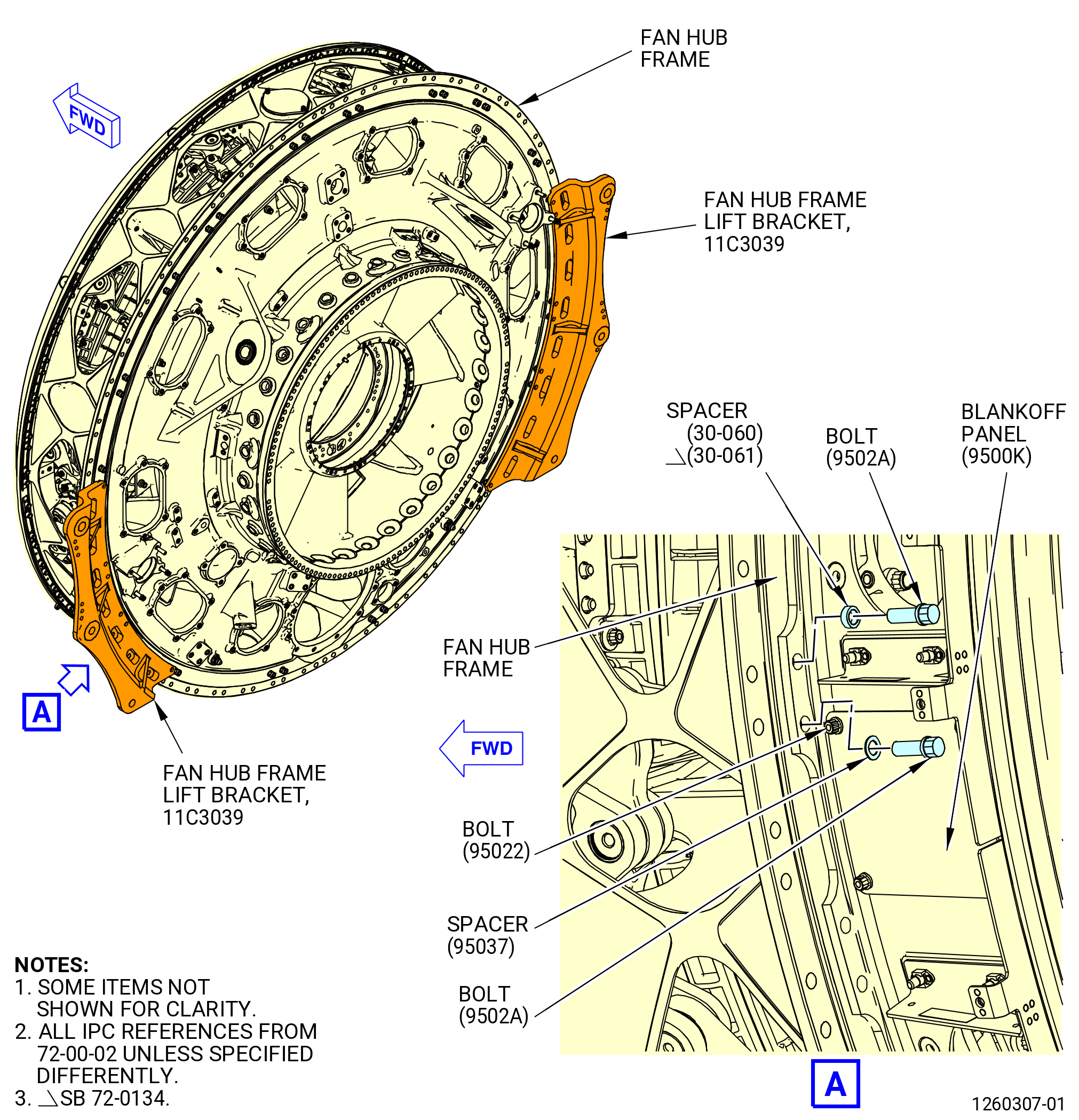
| E. | Remove the fan hub frame lifting brackets and install remaining hardware as follows. Refer to Figure 406. |
| CAUTION: |
|
| (1) | Carefully remove the 11C3039 fan hub frame lift brackets from the left and right sides of the engine as follows: |
| (a) | Remove the bolts that attach the brackets to the fan hub frame. |
| (b) | Make sure that you do not damage the engine when you remove the brackets. |
| (2) | Deleted. |
| (3) | Lubricate the threads and mating surfaces of the bolts with C02-058 graphite. |
| Subtask 72-00-01-420-113 |
| * * * PRE SB 72-0040 |
| * * * SB 72-0050 |
| (4) | Install the remaining bolts (25-520 , 72-00-00) (SIN 9500D) and sleeve spacers (spacer) (30-060 , 72-00-02) (SIN 95070) or (30-061 , 72-00-02) (SIN 95070) into the fan hub module. |
| * * * END PRE SB 72-0040 |
| * * * END SB 72-0050 |
| Subtask 72-00-01-420-114 |
| * * * SB 72-0040 |
| (4).A. | Install the bolts and sleeve spacers (spacer) (30-060 , 72-00-02) (SIN 95070) or (30-061 , 72-00-02) (SIN 95070) into the fan hub module, except at one location on the right side and left side of the engine at blankoff panels (30-140 , 72-00-02) (SIN 9500K). At these two locations, install one bolt (30-675 , 72-00-02) (SIN 9502A) or (30-680 , 72-00-02) (SIN 9502A) with one spacer (30-685 , 72-00-02) (SIN 95037) (thin washer). |
| NOTE: |
|
| * * * END SB 72-0040 |
| Subtask 72-00-01-420-115 |
| (5) | Torque the bolts (25-520 , 72-00-00) (SIN 9500D) to 368-432 lb in. (41.6-48.8 N.m). |
| (6) | If any bolts (30-130 , 72-00-02) (SIN 95022) that attach the blankoff panels (30-140 , 72-00-02) (SIN 9500K) were removed, then install those bolts again. Torque the bolts (30-130 , 72-00-02) (SIN 95022) to 106-124 lb in. (12.0-14.0 N.m). |
|
| Subtask 72-00-01-420-007 |
| * * * PRE SB 72-0050 |
| F. | Install tubes and fairings behind the outlet guide vanes as follows: |
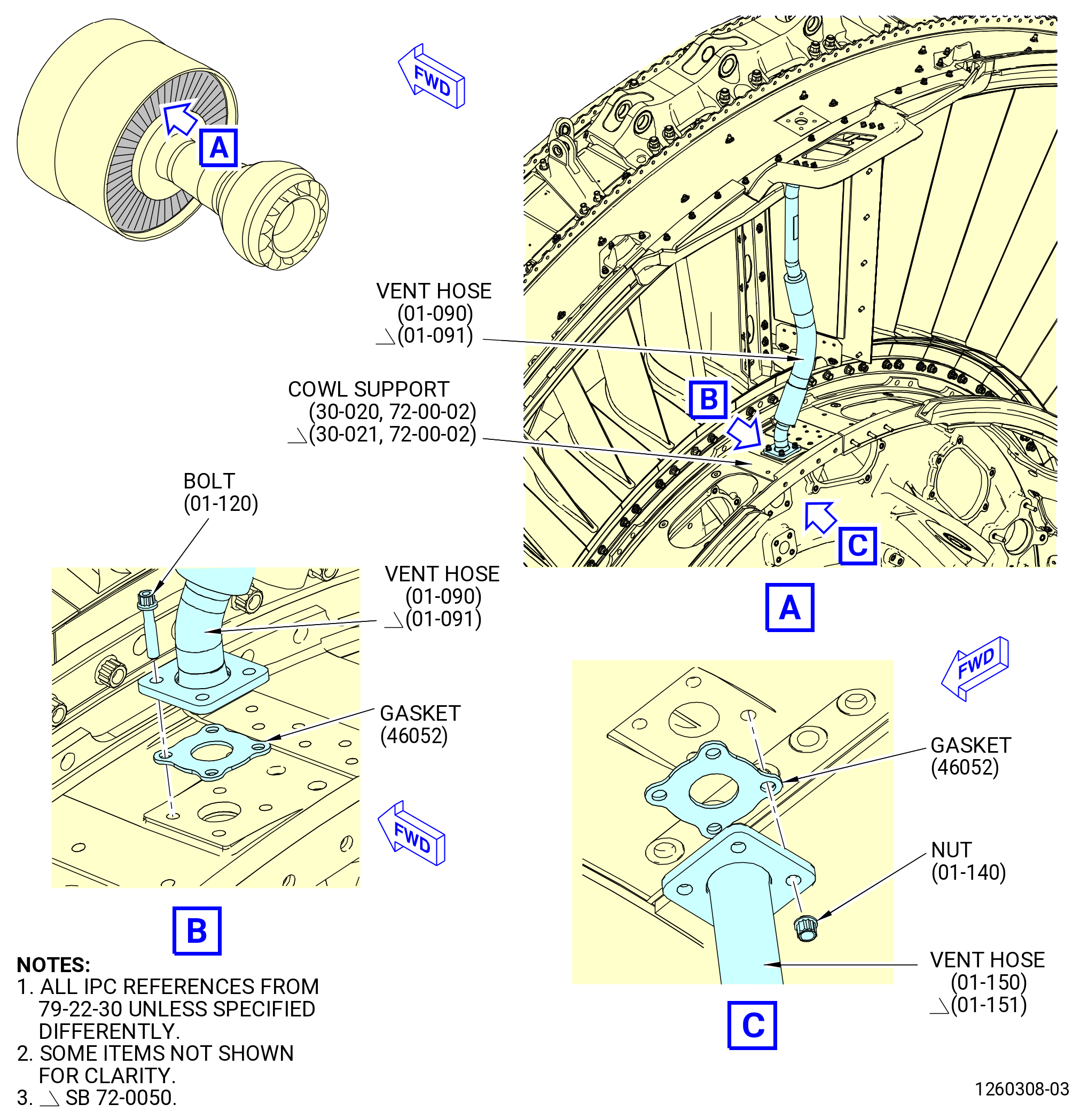
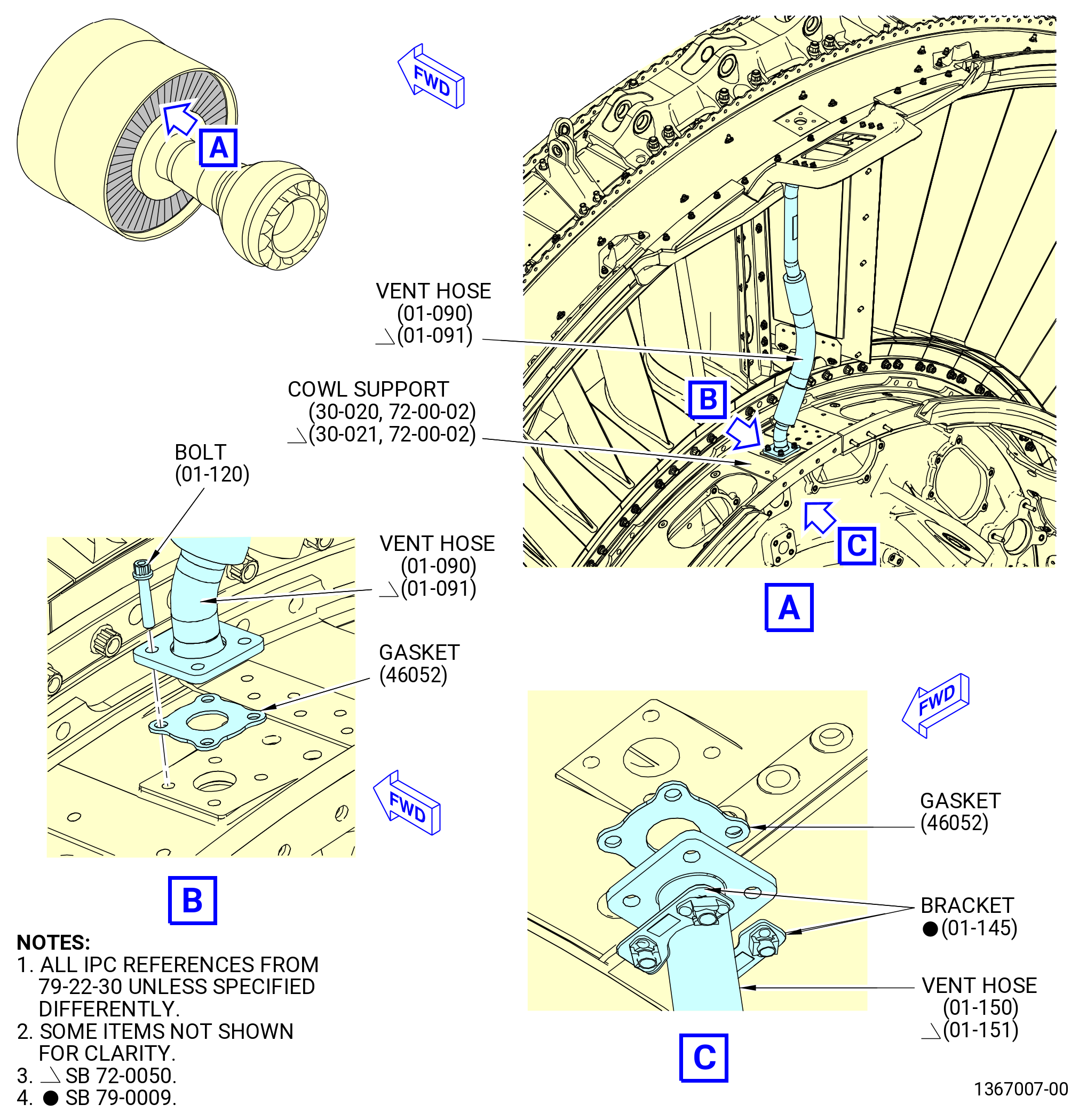
| (1) | Install the oil vent tube and hose (vent hose) (01-090 , 79-22-30) at the 12:00 o'clock position above the fan hub frame as follows. Refer to Figure 407. |
| WARNING: |
|
| (a) | Lubricate two gaskets (01-130 , 79-22-30) (SIN 46052) with C02-019 engine oil or C02-023 engine oil. |
| (b) | Attach the vent hose (01-090 , 79-22-30) through the upper bifurcation strut to the top of cowl support (30-020 , 72-00-02) with one gasket and four bolts (46028). |
| (c) | Attach the oil tank vent tube and hose (vent hose) (01-150 , 79-22-30) (SIN 46005) below the cowl support with one gasket and four nuts (01-140 , 79-22-30) (SIN 46041). |
| (d) | Torque the nuts (01-140 , 79-22-30) (SIN 46041) to 106-124 lb in. (12.0-14.0 N.m). |
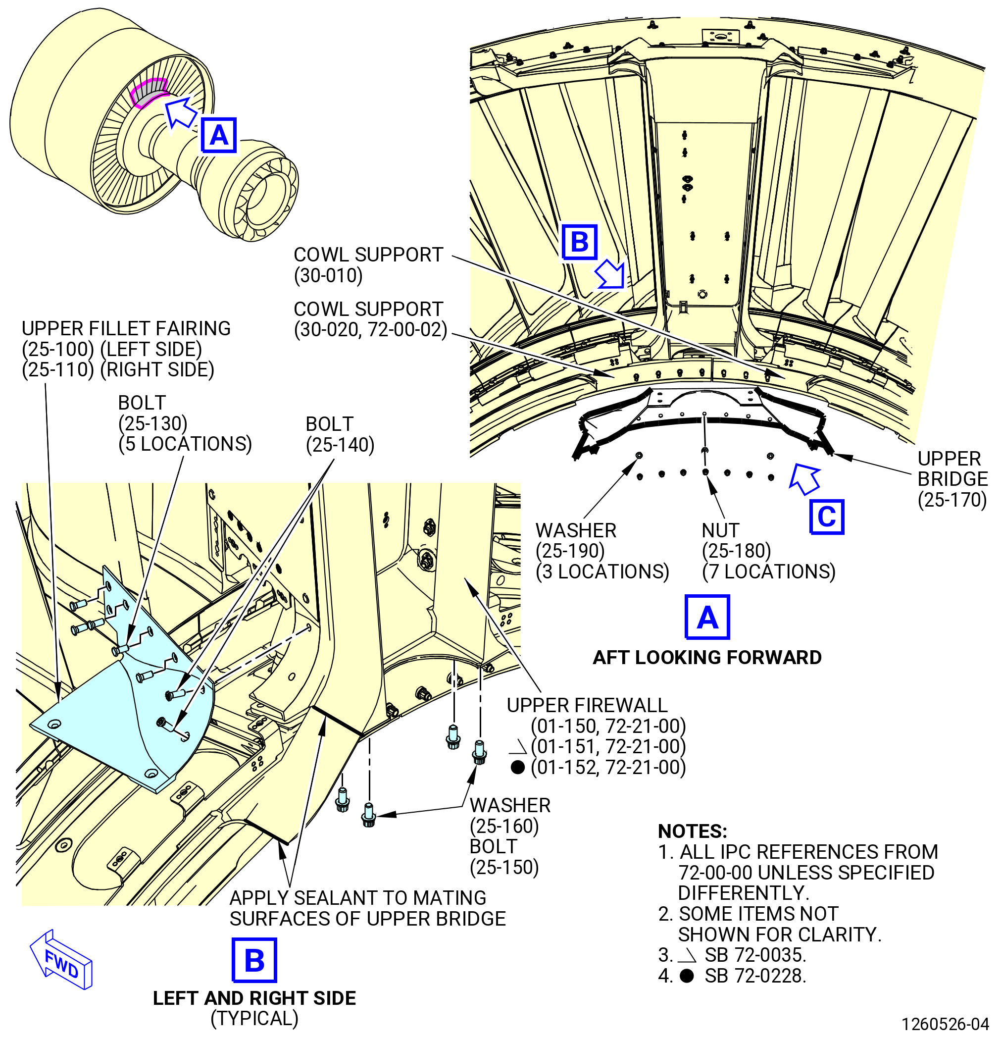
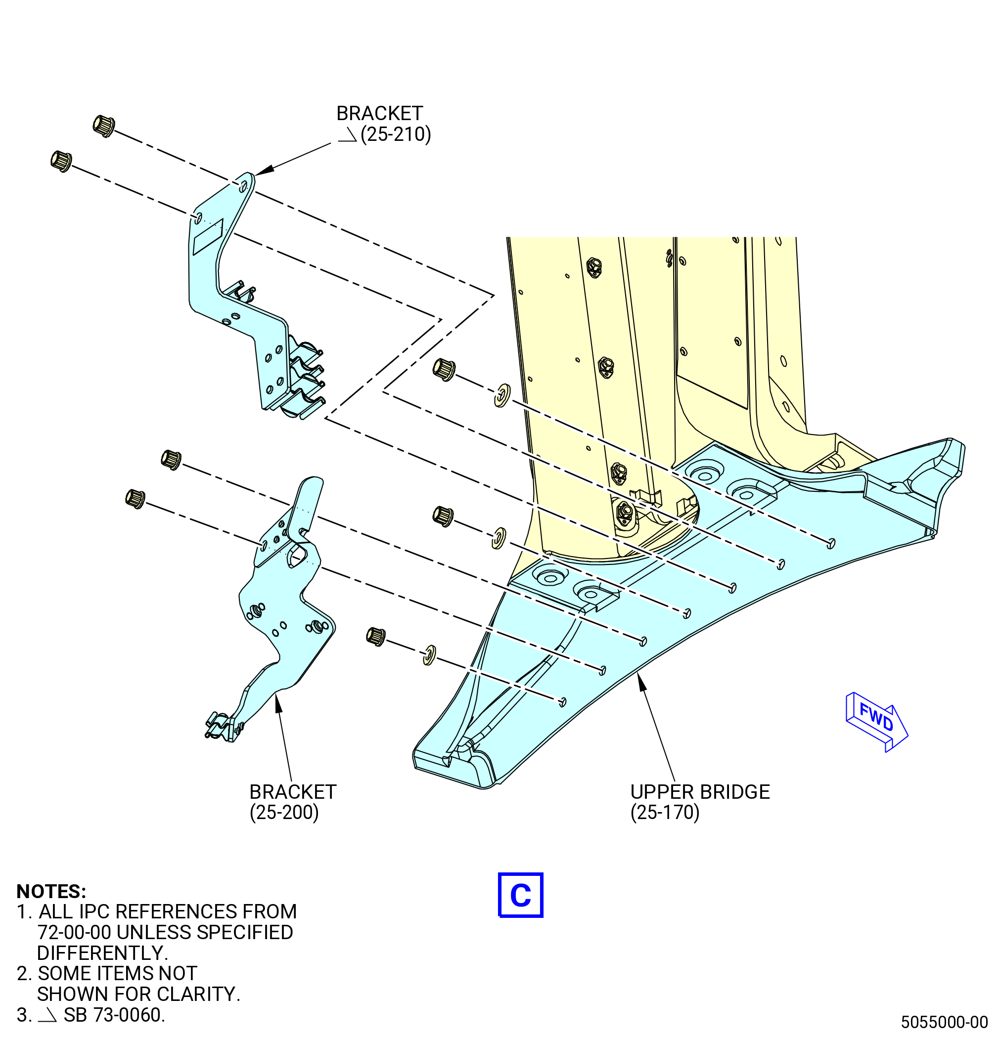
| (2) | Install the upper bifurcation bridge (upper bridge) (25-170 , 72-00-00) as follows. Refer to Figure 408. |
| (a) | Lubricate the seven studs on the cowl support, four bolts (25-150 , 72-00-00), and seven nuts (95040) with C02-058 graphite. |
| (b) | Install the upper bridge (25-170 , 72-00-00) to the aft side of the fan hub frame and over the cowl supports (30-010 , 72-00-02, 30-020 , 72-00-02) at the 12:00 o'clock position. |
| (c) | Attach the upper bridge (25-170 , 72-00-00) (SIN 95002) with three washers (25-190 , 72-00-00) (SIN 95030) and seven nuts (25-180 , 72-00-00) (SIN 95040). |
| (d) | Attach the upper bridge (25-170 , 72-00-00) (SIN 95002) to the upper firewall (01-150 , 72-21-00) (SIN 84401) or (01-151 , 72-21-00) (SIN 84401) or (01-152 , 72-21-00) (SIN 84401) with four bolts (25-150 , 72-00-00) (SIN 84429) and four washers (25-160 , 72-00-00) (SIN 84434). |
| (e) | Torque the bolts (25-150 , 72-00-00) to 106-124 lb in. (12.0-14.0 N.m). |
| NOTE: |
|
| (f) | Deleted. |
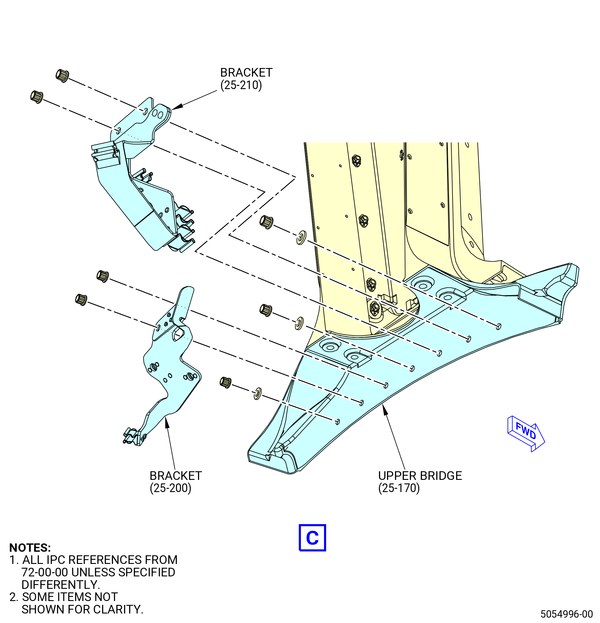
| (3) | Install the electric support bracket (bracket) (25-210 , 72-00-00) (SIN 68812) as follows: |
| (a) | Install the bracket (25-210 , 72-00-00) (SIN 68812) on the upper bifurcation bridge (25-170 , 72-00-00) (SIN 95002) with two nuts (25-180 , 72-00-00) (SIN 95040). |
| (4) | Install the fire suppression support bracket (bracket) (25-200 , 72-00-00) (SIN 9931A) as follows: |
| (a) | Install the bracket (25-200 , 72-00-00) (SIN 9931A) with two nuts (25-180 , 72-00-00) (SIN 95040). |
| (5) | Torque the seven nuts to 69 to 81 lb in. (7.7 to 9.1 Nm). |
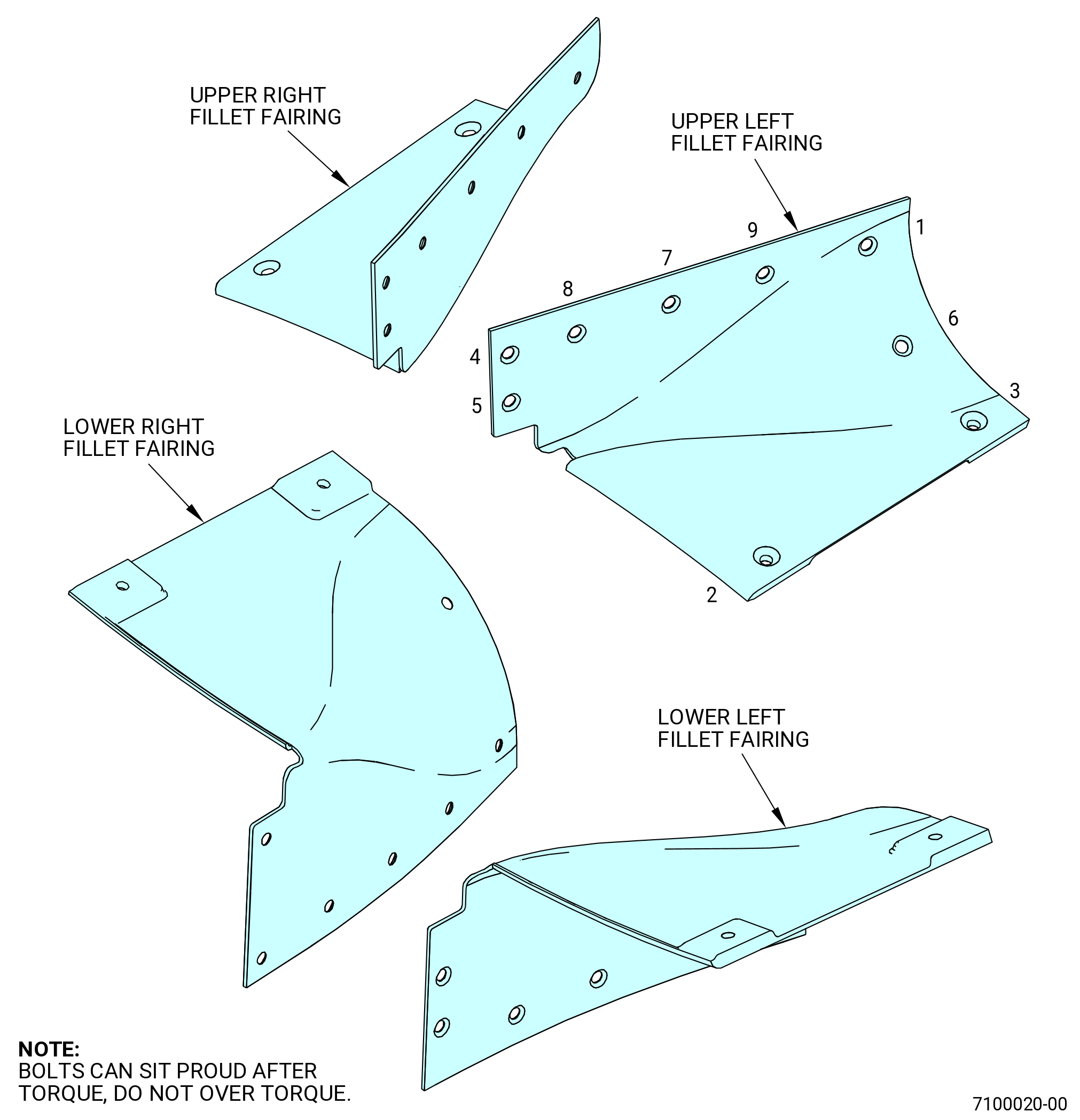
| (6) | Install the upper fillet fairings as follows: |
| (a) | Lubricate the threads and mating surfaces of ten bolts (84427), four screws (84428), and four bolts (8442H) with C02-058 graphite. |
| (b) | Install the fillet fairing (84407) to the left side of the upper bifurcation with five bolts (84427), two screws (84428), and two bolts (8442H). |
| (c) | Install fillet fairing (8440A) to the right side of the upper bifurcation with five bolts (84427), two screws (84428) and two bolts (8442H). |
| (d) | Deleted. |
| (7) | Apply C01-007 RTV to the upper bridge as follows: |
| WARNING: |
|
| (a) | Clean the upper bridge and the adjacent surfaces with C04-035 isopropyl alcohol. |
| (b) | Apply C01-007 RTV to the transition areas where the upper bridge touches other surfaces. Make sure that there is a smooth transition of the sealant between mating components. |
| NOTE: |
|
| (c) | Let the C01-007 RTV cure for 12 hours. |
| * * * END PRE SB 72-0050 |
| Subtask 72-00-01-420-068 |
| * * * SB 72-0050 |
| F.A. | Install tubes and fairings behind the outlet guide vanes as follows: |
| (1) | Install the oil vent tube and hose (vent hose) (01-091 , 79-22-30) at the 12:00 o'clock position above the fan hub frame as follows. Refer to Figure 407. |
| WARNING: |
|
| (a) | Lubricate two gaskets (01-130 , 79-22-30) (SIN 46052) with C02-019 engine oil or C02-023 engine oil. |
| (b) | Attach the oil vent hose tube (vent tube) (01-091 , 79-22-30) (SIN 46004) through the upper bifurcation strut to the top of cowl support (30-021 , 72-00-02) (SIN 95008) with one gasket and four bolts (01-120 , 79-22-30) (SIN 46028). |
| Subtask 72-00-01-420-071 |
| * * * PRE SB 79-0009( Oil Vent Hose Tube Attached with Nuts ) |
| (c) | Attach the vent tube (01-091 , 79-22-30) (SIN 46004) and vent hose (01-151 , 79-22-30) (SIN 46005) below the cowl support with one gasket and four nuts (01-140 , 79-22-30) (SIN 46041). |
| * * * END PRE SB 79-0009 |
| Subtask 72-00-01-420-072 |
| * * * SB 79-0009( Oil Vent Hose Tube Attached with Bolts ) |
| (c).A. | Attach the vent tube (01-091 , 79-22-30) (SIN 46004) and vent hose (01-151 , 79-22-30) (SIN 46005) below the cowl support with one gasket and two brackets (01-145 , 79-22-30) (SIN 46014). |
| * * * END SB 79-0009 |
| Subtask 72-00-01-420-073 |
| * * * PRE SB 79-0009( Oil Vent Hose Tube Attached with Nuts ) |
| (d) | Torque the nuts (01-140 , 79-22-30) (SIN 46041) to 106-124 lb in. (12.0-14.0 N.m). |
| * * * END PRE SB 79-0009 |
| Subtask 72-00-01-420-074 |
| * * * SB 79-0009( Oil Vent Hose Tube Attached with Bolts ) |
| (d).A. | Torque the bolts (01-120 , 79-22-30) (SIN 46028) to 106-124 lb in. (12.0-14.0 N.m). |
| * * * END SB 79-0009 |
| Subtask 72-00-01-420-075 |
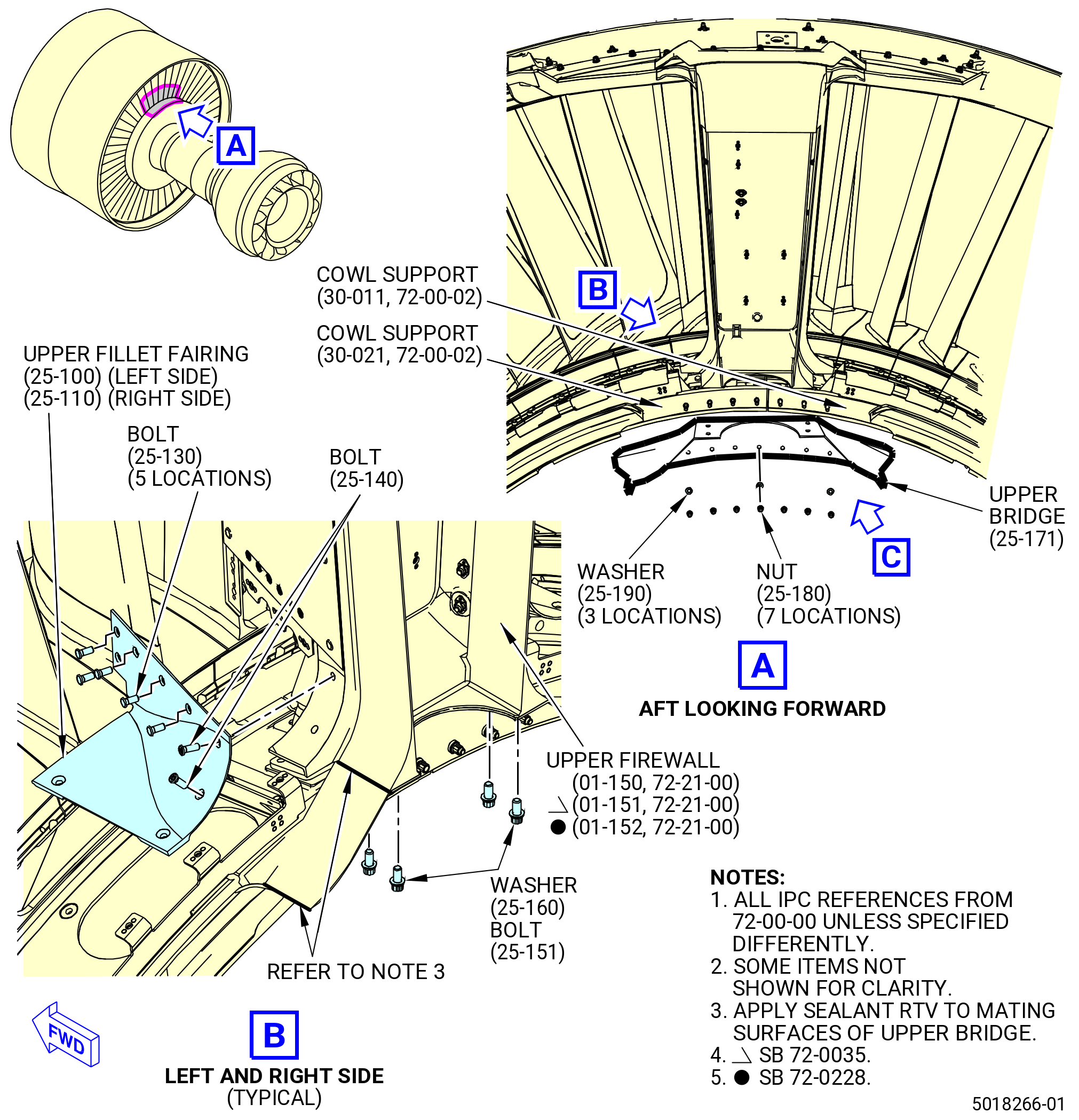
| (2) | Install the upper bifurcation bridge (upper bridge) (25-171 , 72-00-00) as follows. Refer to Figure 408. |
| (a) | Lubricate the seven studs on the cowl support, four bolts (25-151 , 72-00-00), and seven nuts (95040) with C02-058 graphite. |
| (b) | Install the upper bridge (25-171 , 72-00-00) to the aft side of the fan hub frame and over the cowl supports (30-011 , 72-00-02, 30-021 , 72-00-02) at the 12:00 o'clock position. |
| (c) | Attach the upper bridge (25-171 , 72-00-00) with three washers (25-190 , 72-00-00) (SIN 95030) and seven nuts (25-180 , 72-00-00) (SIN 95040). |
| (d) | Attach the upper bridge (25-171 , 72-00-00) (SIN 95002) to the upper firewall (01-150 , 72-21-00) (SIN 84401) or (01-151 , 72-21-00) (SIN 84401) or (01-152 , 72-21-00) (SIN 84401) with four bolts (25-151 , 72-00-00) (SIN 84429) and four washers (25-160 , 72-00-00) (SIN 84434). |
| (e) | Torque the bolts (25-151 , 72-00-00) to 106-124 lb in. (12.0-14.0 N.m). |
| NOTE: |
|
| (f) | Deleted. |
| (3) | Install the bracket (25-210 , 72-00-00) (SIN 68812) as follows: |
| (a) | Install the bracket (25-210 , 72-00-00) (SIN 68812) on the upper bifurcation bridge (25-171 , 72-00-00) (SIN 95002) with two nuts (25-180 , 72-00-00) (SIN 95040). |
| (4) | Install the bracket (25-200 , 72-00-00) (SIN 9931A) as follows: |
| (a) | Install the bracket (25-200 , 72-00-00) (SIN 9931A) with two nuts (25-180 , 72-00-00) (SIN 95040). |
| (5) | Torque the seven nuts to 69 to 81 lb in. (7.7 to 9.1 Nm). |
| (6) | Install the upper fillet fairings as follows: |
| (a) | Lubricate the threads and mating surfaces of ten bolts (84427), four screws (84428), and four bolts (8442H) with C02-058 graphite. |
| (b) | Install the fillet fairing (84407) to the left side of the upper bifurcation with five bolts (84427), two screws (84428), and two bolts (8442H). |
| (c) | Install fillet fairing (8440A) to the right side of the upper bifurcation with five bolts (84427), two screws (84428) and two bolts (8442H). |
| (d) | Deleted. |
| (7) | Apply C01-007 RTV to the upper bridge as follows: |
| WARNING: |
|
| (a) | Clean the upper bridge and the adjacent surfaces with C04-035 isopropyl alcohol. |
| (b) | Apply C01-007 RTV to the transition areas where the upper bridge touches other surfaces. Make sure that there is a smooth transition of the sealant between mating components. |
| NOTE: |
|
| (c) | Let the C01-007 RTV cure for 12 hours. |
| * * * END SB 72-0050 |
|
|
|
|
| Subtask 72-00-01-420-008 |
| G. | Install the leading edge splitter (booster splitter) (84202) as follows. Refer to Figure 409. |
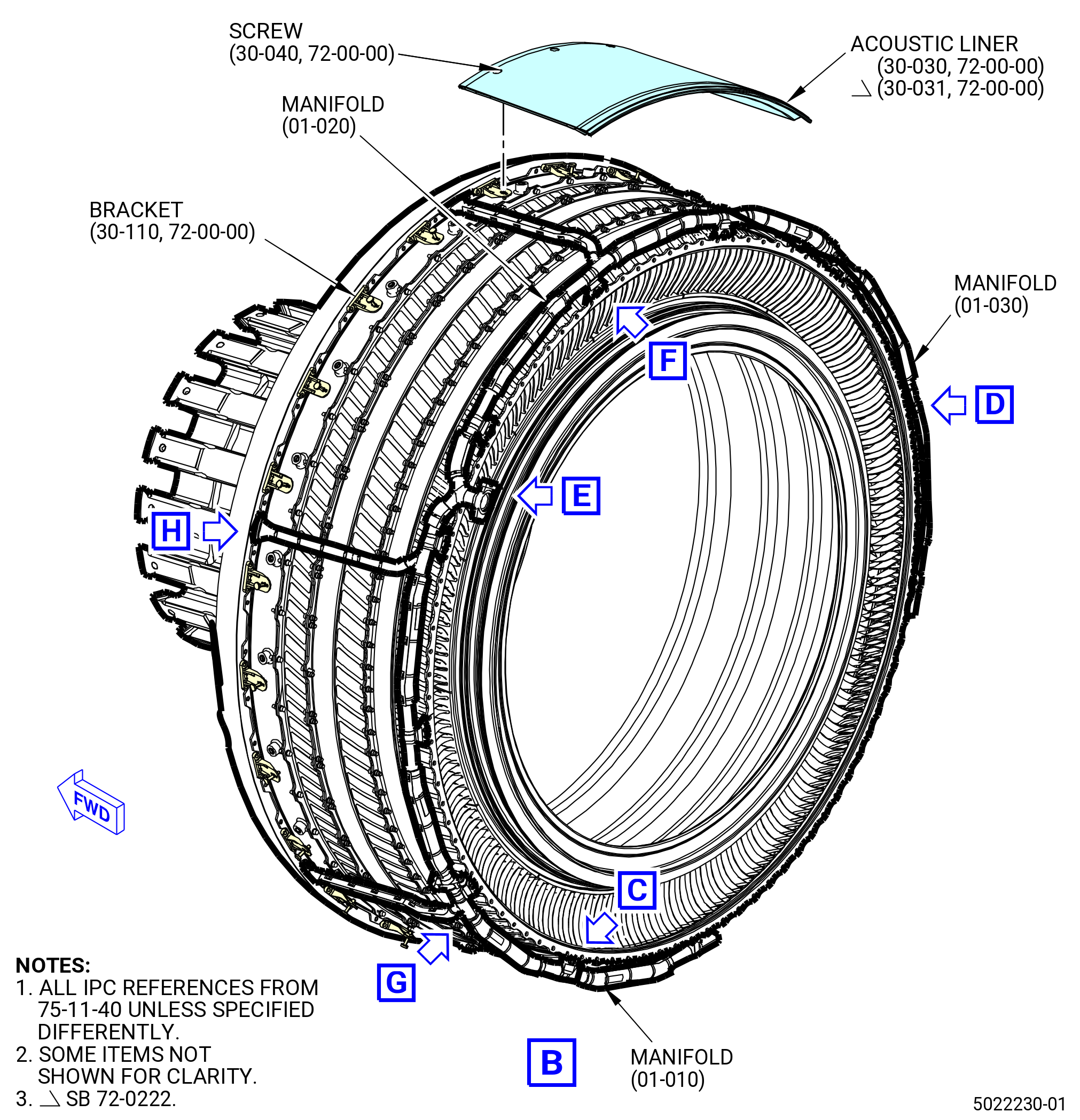
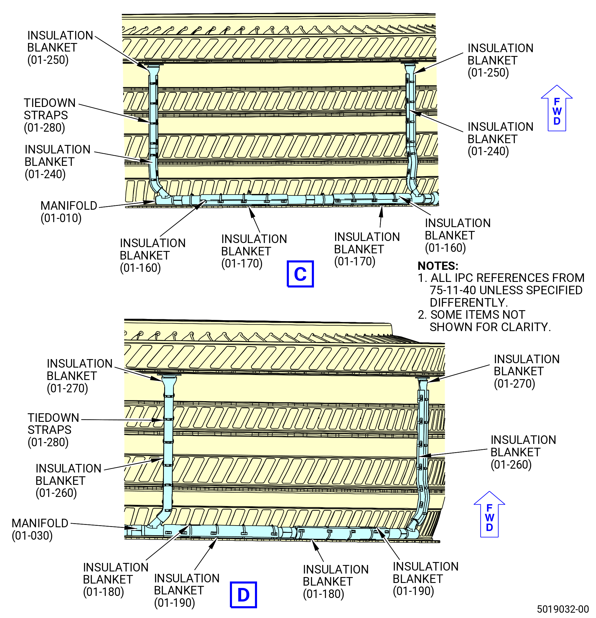
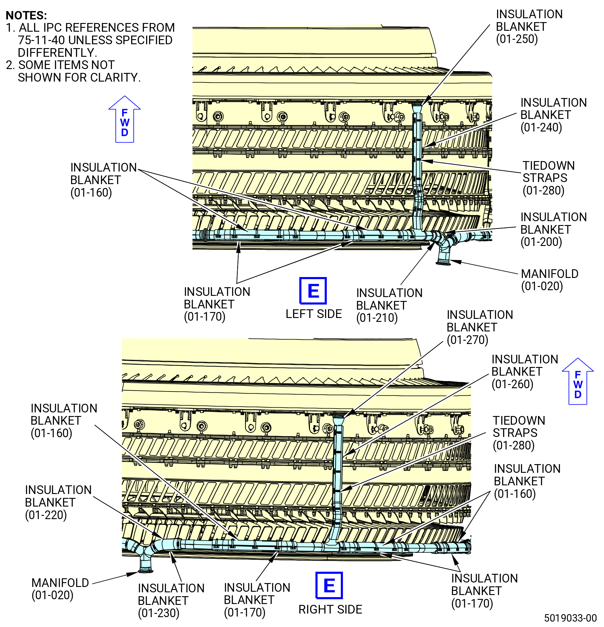
| (1) | Install the insulation blankets to the manifold (01-010 , 75-11-40) (SIN 63705) as follows: |
| (a) | Install two insulation blankets (01-160 , 75-11-40) (SIN 63790) on the forward side of the manifold. |
| (b) | Install two insulation blankets (01-170 , 75-11-40) (SIN 63791) on the aft side of the manifold. |
| (c) | Attach firmly each insulation blanket pair with five tiedown straps (01-280 , 75-11-40) (SIN 6379H). Make sure that the tail clip of the tiedown strap is outboard, if not, it will rub the booster case. |
| (d) | Install two insulation blankets (01-240 , 75-11-40) (SIN 6379D) on the inboard side of the manifold. |
| (e) | Install two insulation blankets (01-250 , 75-11-40) (SIN 6379E) on the outboard side of the manifold. |
| (f) | Attach firmly each insulation blanket pair with six tiedown straps (01-280 , 75-11-40) (SIN 6379H). Make sure that the tail clip of the tiedown strap is outboard, if not, it will rub the booster case. |
| (2) | Install the insulation blankets to the manifold (01-030 , 75-11-40) (SIN 63707) as follows: |
| (a) | Install two insulation blankets (01-180 , 75-11-40) (SIN 63792) on the forward and aft sides of the manifold. |
| (b) | Install two insulation blankets (01-190 , 75-11-40) (SIN 63793) on the aft and forward sides of the manifold. |
| (c) | Attach firmly each insulation blanket pair with five tiedown straps (01-280 , 75-11-40) (SIN 6379H). Make sure that the tail clip of the tiedown strap is outboard, if not, it will rub the booster case. |
| (d) | Install two insulation blankets (01-260 , 75-11-40) (SIN 6379F) on the inboard side of the manifold. |
| (e) | Install two insulation blankets (01-270 , 75-11-40) (SIN 6379G) on the outboard side of the manifold. |
| (f) | Attach firmly each insulation blanket pair with six tiedown straps (01-280 , 75-11-40) (SIN 6379H). Make sure that the tail clip of the tiedown strap is outboard, if not, it will rub the booster case. |
| (3) | Install the insulation blankets to the manifold (01-020 , 75-11-40) (SIN 63706) as follows: |
| (a) | Install two insulation blankets (01-160 , 75-11-40) (SIN 63790) on the forward side of the left side of the manifold. |
| (b) | Install two insulation blankets (01-170 , 75-11-40) (SIN 63791) on the aft side of the left side of the manifold. |
| (c) | Attach firmly each insulation blanket pair with five tiedown straps (01-280 , 75-11-40) (SIN 6379H). Make sure that the tail clip of the tiedown strap is outboard, if not, it will rub the booster case. |
| (d) | Install one insulation blanket (01-240 , 75-11-40) (SIN 6379D) on the inboard side of the left side of the manifold. |
| (e) | Install one insulation blanket (01-250 , 75-11-40) (SIN 6379E) on the outboard side of the left side of the manifold. |
| (f) | Attach firmly each insulation blanket pair with six tiedown straps (01-280 , 75-11-40) (SIN 6379H). Make sure that the tail clip of the tiedown strap is outboard, if not, it will rub the booster case. |
| (g) | Install one insulation blanket (01-200 , 75-11-40) (SIN 63794) on the inboard side of the left side of the manifold. |
| (h) | Install one insulation blanket (01-210 , 75-11-40) (SIN 63795) on the outboard side of the left side of the manifold. |
| (i) | Attach firmly the insulation blanket pair with one tiedown strap (01-280 , 75-11-40) (SIN 6379H). Make sure that the tail clip of the tiedown strap is outboard, if not, it will rub the booster case. |
| (j) | Install three insulation blankets (01-160 , 75-11-40) (SIN 63790) on the forward side of the right side of the manifold. |
| (k) | Install three insulation blankets (01-170 , 75-11-40) (SIN 63791) on the aft side of the right side of the manifold. |
| (l) | Attach firmly each insulation blankets pair with five tiedown straps (01-280 , 75-11-40) (SIN 6379H). Make sure that the tail clip of the tiedown strap is outboard, if not, it will rub the booster case. |
| (m) | Install one insulation blanket (01-260 , 75-11-40) (SIN 6379F) on the inboard side of the right side of the manifold. |
| (n) | Install one insulation blanket (01-270 , 75-11-40) (SIN 6379G) on the outboard side of the right side of the manifold. |
| (o) | Attach firmly each insulation blanket pair with six tiedown straps (01-280 , 75-11-40) (SIN 6379H). Make sure that the tail clip of the tiedown strap is outboard, if not, it will rub the booster case. |
| (p) | Install one insulation blanket (01-220 , 75-11-40) (SIN 63796) on the inboard side of the right side of the manifold. |
| (q) | Install one insulation blanket (01-230 , 75-11-40) (SIN 63797) on the outboard side of the right side of the manifold. |
| (r) | Attach firmly the insulation blanket pair with two tiedown straps (01-280 , 75-11-40) (SIN 6379H). Make sure that the tail clip of the tiedown strap is outboard, if not, it will rub the booster case. |
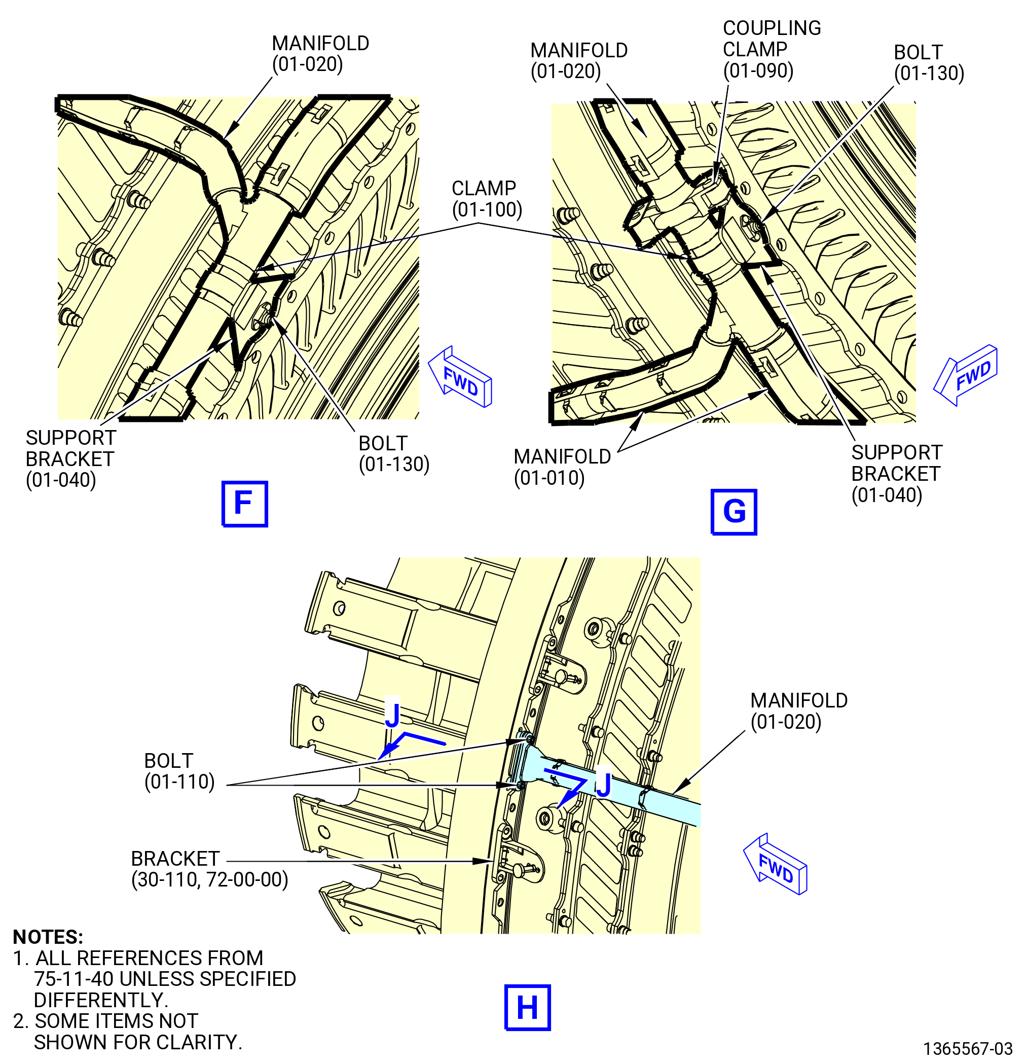
| (4) | Install the manifold (01-020 , 75-11-40) (SIN 63706) on the fan booster assembly as follows: |
| (a) | Install the manifold to the BAI air tube (01-180 , 75-11-30) (SIN 63704) with a ring seal (01-080 , 75-11-40) (SIN 63752). |
| (b) | Attach the manifold and the BAI air tube with a coupling clamp (01-120 , 75-11-40) (SIN 63783). |
| (c) | Torque the coupling clamp (01-120 , 75-11-40) (SIN 63783) to 60-70 lb in. (6.8-7.9 N.m). |
| (5) | Install the manifold (01-010 , 75-11-40) (SIN 63705) on the fan booster assembly as follows: |
| (a) | Install the manifold (01-010 , 75-11-40) (SIN 63705) to the manifold (01-020 , 75-11-400) (SIN 63706) with a ring seal (01-140 , 75-11-40) (SIN 63751). |
| (b) | Attach the two manifolds with a coupling clamp (01-090 , 75-11-40) (SIN 63781). |
| (c) | Torque the coupling clamp (01-090 , 75-11-40) (SIN 63781) to 51-59 lb in. (5.8-6.7 N.m). |
| (6) | Install the manifold (01-030 , 75-11-40) (SIN 63707) on the fan booster assembly as follows: |
| (a) | Install the manifold (01-030 , 75-11-40) (SIN 63705) to the manifold (01-020 , 75-11-40) (SIN 63706) with a ring seal (01-140 , 75-11-40) (SIN 63751). |
| (b) | Attach the two manifolds with a coupling clamp (01-090 , 75-11-40) (SIN 63781). |
| (c) | Torque the coupling clamp (01-090 , 75-11-40) (SIN 63781) to 51-59 lb in. (5.8-6.7 N.m). |
| (7) | Attach the manifolds (01-010 , 75-11-40) (SIN 63705), (01-020 , 75-11-40) (SIN 63706), and (01-030 , 75-11-40) (SIN 63707) to the support brackets (01-040 , 75-11-40) (SIN 63713) and (01-160 , 75-11-40) (SIN 63714) on the fan booster assembly with 11 loop clamps (01-100 , 75-11-40) (SIN 63782) and machine bolts (bolts) (01-130 , 75-11-40) (SIN 63720). Do not torque the bolts at this time. |
| Subtask 72-00-01-210-001 |
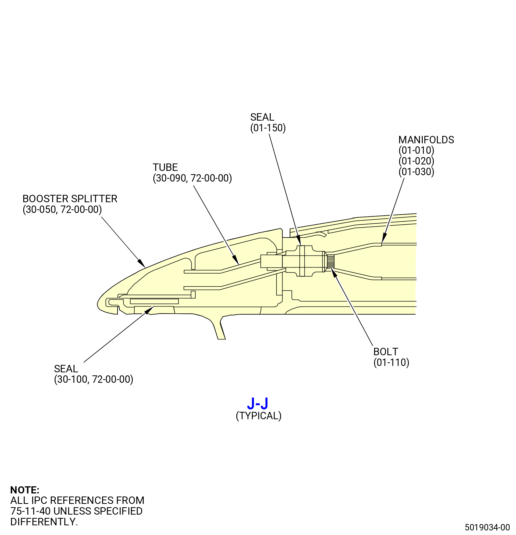
| (8) | Make sure that the seal (30-100 , 72-00-00) (SIN 63759) is installed. If it is not, install the seal. Refer to TASK 72-00-22-420-801 (72-00-22, INSTALLATION 001). |
| Subtask 72-00-01-420-111 |
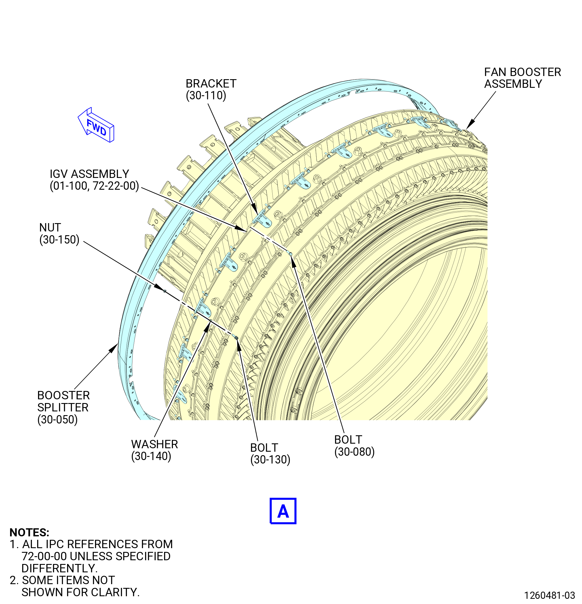
| (9) | Attach 24 brackets (30-110 , 72-00-00) (SIN 83710) to the booster splitter with machine bolts (30-130 , 72-00-00) (SIN 83721), flat washers (30-140 , 72-00-00) (SIN 83731), and self-locking nuts (nuts) (30-150 , 72-00-00) (SIN 83741). Boltheads aft and washers under the bolt head. |
| (10) | Torque the machine bolts (30-130 , 72-00-00) (SIN 83721) to 60-70 lb in. (6.8-7.9 N.m). |
| (11) | Install the booster splitter (30-050 , 72-00-00) (SIN 84202) as follows: |
| WARNING: |
|
| (a) | Apply C02-058 graphite to the threads of 12 machine bolts (bolts) (01-110 , 75-11-40) (SIN 63721). |
| (b) | Put the booster splitter against the aft flange of the IGV assembly (01-100 , 72-22-00) (SIN 837A0). |
| (c) | Align the part number of the booster splitter with the notch in the flange of the fan booster assembly at the 12:00 o'clock position, top vertical centerline and align the openings in the aft face of the booster splitter with the tubes (30-090 , 72-00-00) (SIN 6370B), seals (01-150 , 75-11-40) (SIN 63755), and manifolds (01-010 , 75-11-40) (SIN 63705), (01-020 , 75-11-40) (SIN 63706), and (01-030 , 75-11-40) (SIN 63707). |
| (d) | Install the 12 bolts (01-110 , 75-11-40) (SIN 63721) to attach the manifolds to the booster splitter. Do not torque the bolts at this time. |
| (12) | Torque the bolts (01-130 , 75-11-40) (SIN 63720) to 60-70 lb in. (6.8-7.9 N.m). |
| WARNING: |
|
| (13) | Lubricate the threads and mating surfaces of 48 bolts (30-080 , 72-00-00) (SIN 837F0) with C02-058 graphite. |
| (14) | Attach the booster splitter to the flange of the IGV assembly with 48 bolts (30-080 , 72-00-00) (SIN 837F0). |
| (15) | Torque the bolts (30-080 , 72-00-00) (SIN 837F0) to 85 lb in. (9.6 N.m) in a criss-cross pattern. |
| (16) | Torque the bolts (30-080 , 72-00-00) (SIN 837F0) to 106-124 lb in. (12.0-14.0 N.m) again in a criss-cross pattern. |
| (17) | Do a 360-degree torque check of the bolts to 106-124 lb in. (12.0-14.0 N.m). |
| (18) | Torque the bolts (01-110 , 75-11-40) (SIN 63721) to 51-59 lb in. (5.8-6.7 N.m). |
| Subtask 72-00-01-220-003 |
| (19) | Do a visual inspection of the fan booster area. Make sure that there is no damage and the area is clear of tools and debris. |
| Subtask 72-00-01-420-009 |
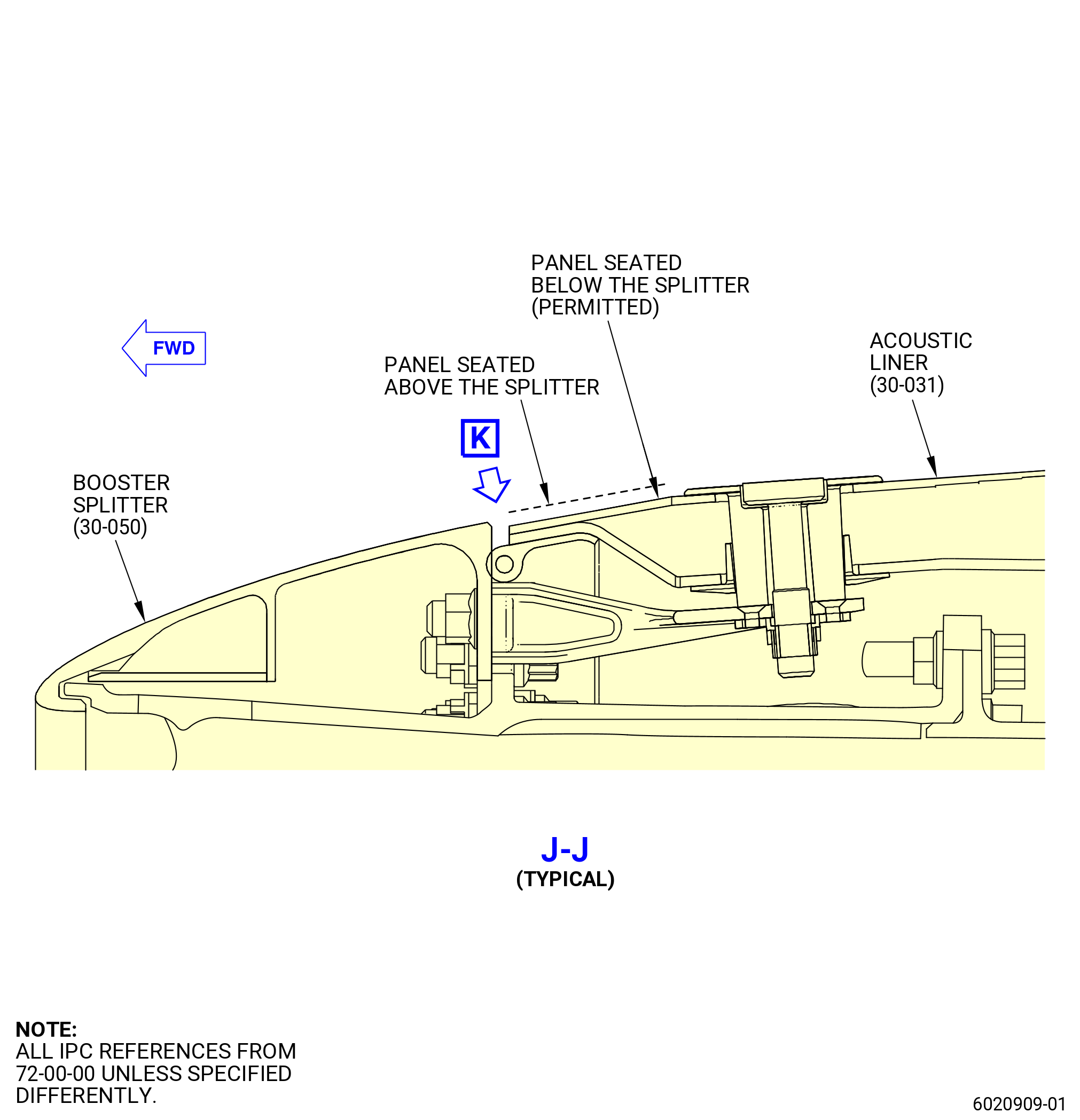
| H. | Install the fan duct inner acoustic liners (acoustic liners) (30-030 , 72-00-00) (SIN 84200) or (30-031 , 72-00-00) (SIN 84200). Refer to Figure 409 and do as follows: |
| (1) | Apply C02-058 graphite to the threads of 24 screws (84220). |
| (2) | Apply C02-008 petroleum jelly to the aft end of the acoustic liners to ease installation and prevent the rubber from tearing. |
| CAUTION: |
|
| CAUTION: |
|
| (3) | Install the first acoustic liner to bracket (30-110 , 72-00-00) (SIN 83710) from the 11:00 o'clock position to 1:00 o'clock position on the aft side of the booster splitter fairing with four screws (84220). The acoustic liners should span across (not split at) at the 12:00 o'clock and 6:00 o'clock position centerlines. |
| (4) | Install the remaining five liners to the outer diameter of the fan booster assembly between the booster splitter flange and the fan case outlet guide vanes with 20 screws (84220). |
| CAUTION: |
|
| CAUTION: |
|
| (5) | Torque all screws (84220) to 60-70 lb in. (6.8-7.9 N.m). |
| (6) | Wait 15 minutes, then torque the screws (84220) again to 60-70 lb in. (6.8-7.9 N.m). |
| Subtask 72-00-01-220-004 |
| (7) | Do a visual inspection of the acoustic liners (30-030 , 72-00-00) (SIN 84200) or (30-031 , 72-00-00) (SIN 84200). Make sure that there is no damage and that the area is clear of tools and unwanted material. |
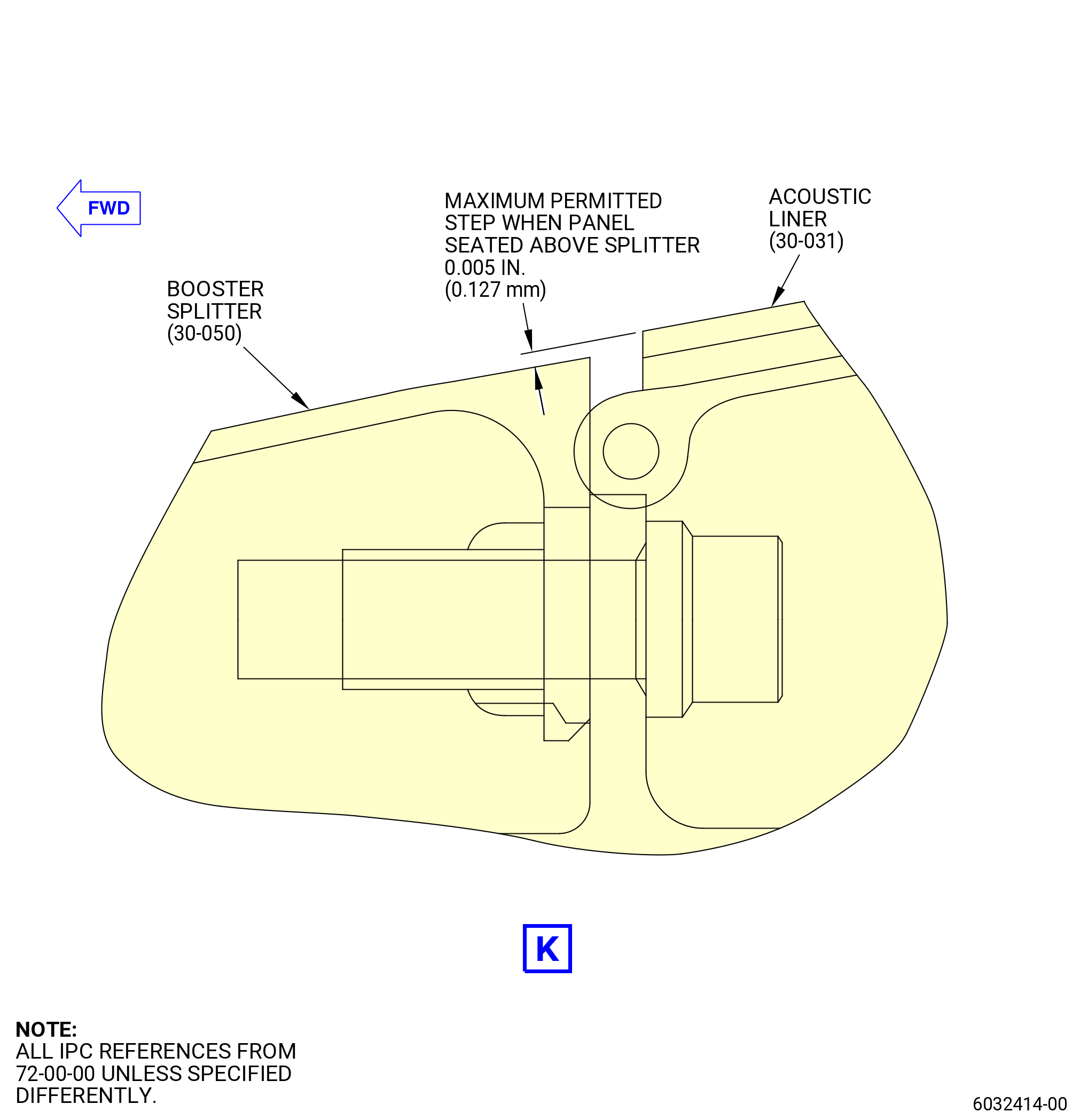
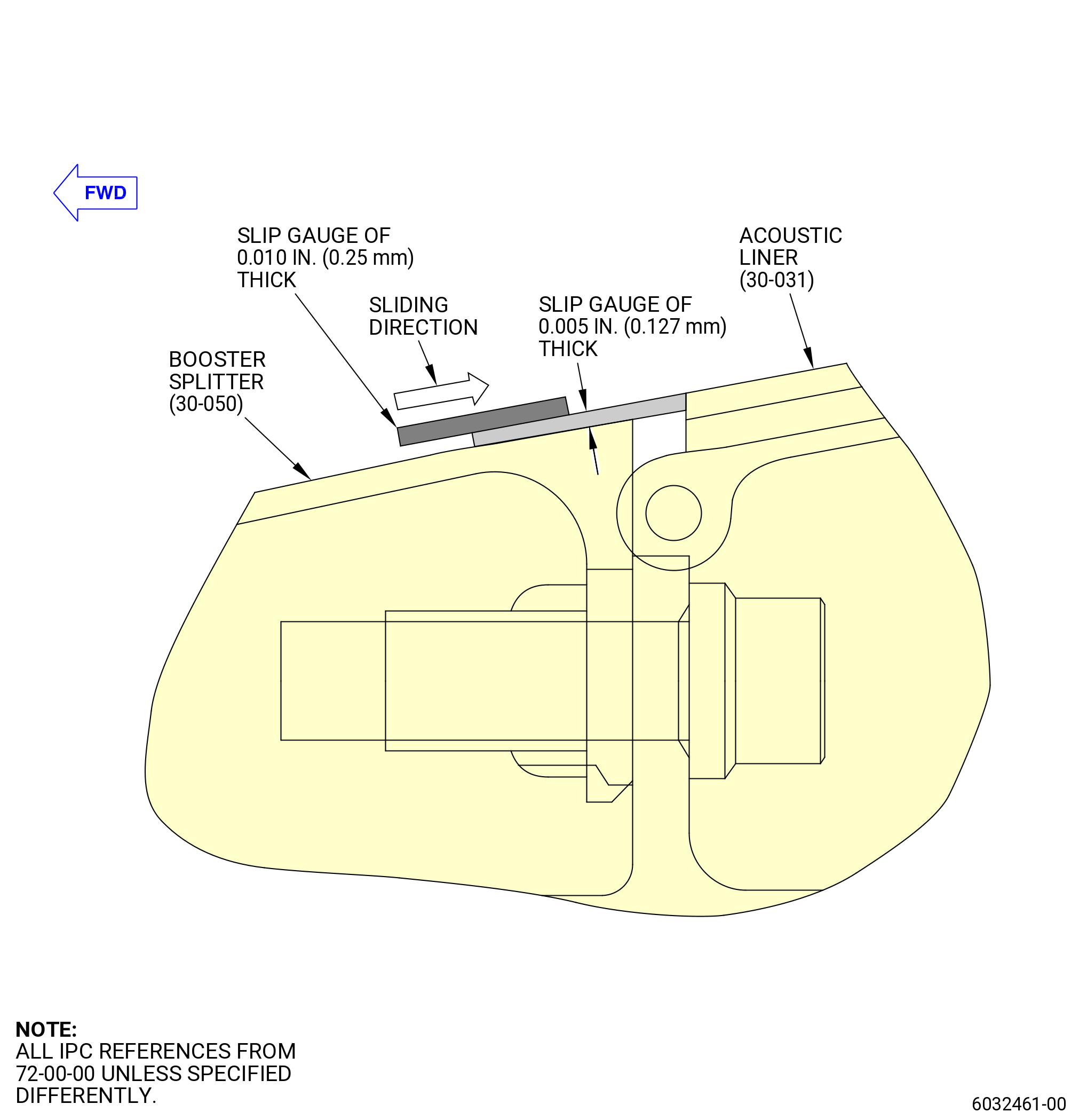
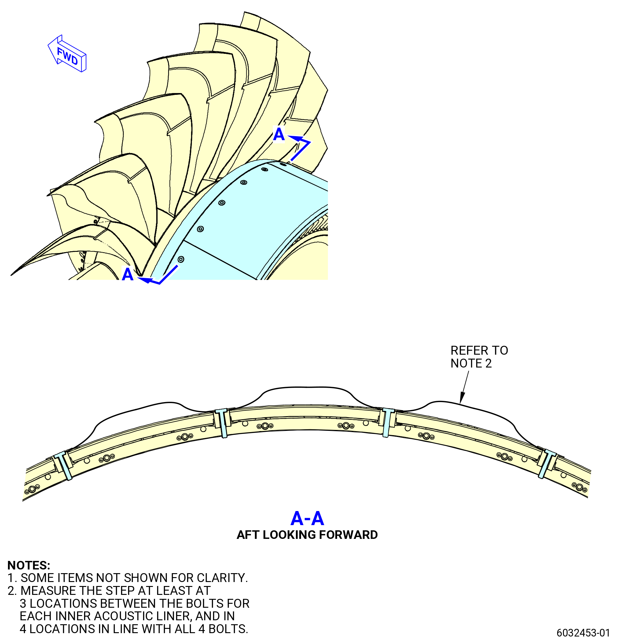
| (8) | Make sure that the booster acoustic panel leading edge has a step of not more than 0.005 inches (0.127 mm) above the splitter. Refer to Figure 409 (sheet 8 through sheet 12) and do as follows: |
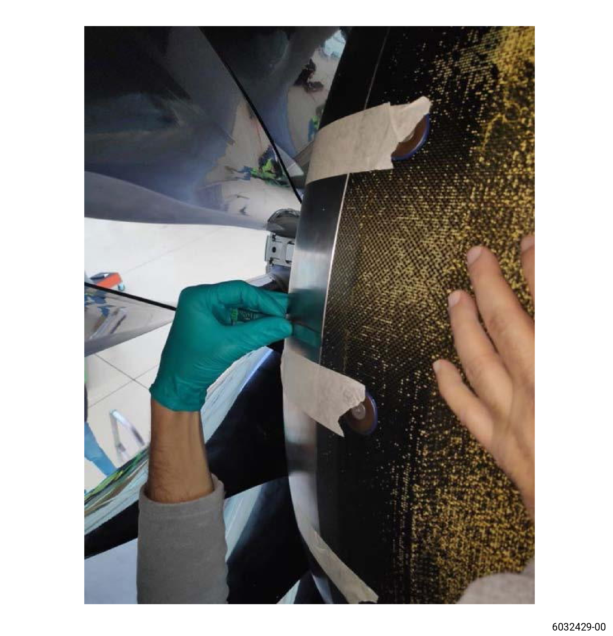
| (a) | Arrange a gauge block/slip gauge that is 0.005 inches |(0.127 mm) on the surface of the booster splitter upstream of the leading edge of the inner acoustic liner. Slide another gauge block/slip gauge of 0.01 inches (0.25 mm) in thickness or more above the 0.005 inches (0.127 mm) gauge block/slip gauge towards the inner acoustic liner. If the gauge block/slip gauge of 0.01 inches (0.25 mm) faces resistance at the leading edge of the acoustic liner, then the step is more than 0.005 inches (0.127 mm). If the gauge block/slip gauge of 0.01 inches (0.25 mm) crosses the leading edge of the acoustic liner, then the step is equal or less than 0.005 inches (0.127 mm). Refer to Figure 409 (sheet 10). |
| (b) | If the step is more than 0.005 inches (0.127 mm), do the steps to remove and install the booster inner acoustic liners again. |
| (c) | Do this step measurement at least at three locations between the bolts and at all 4 bolt locations for each inner acoustic liner. Refer to Figure 409 (sheet 11 and sheet 12). |
| NOTE: |
|
| Subtask 72-00-01-420-010 |
| * * * PRE SB 72-0050 |
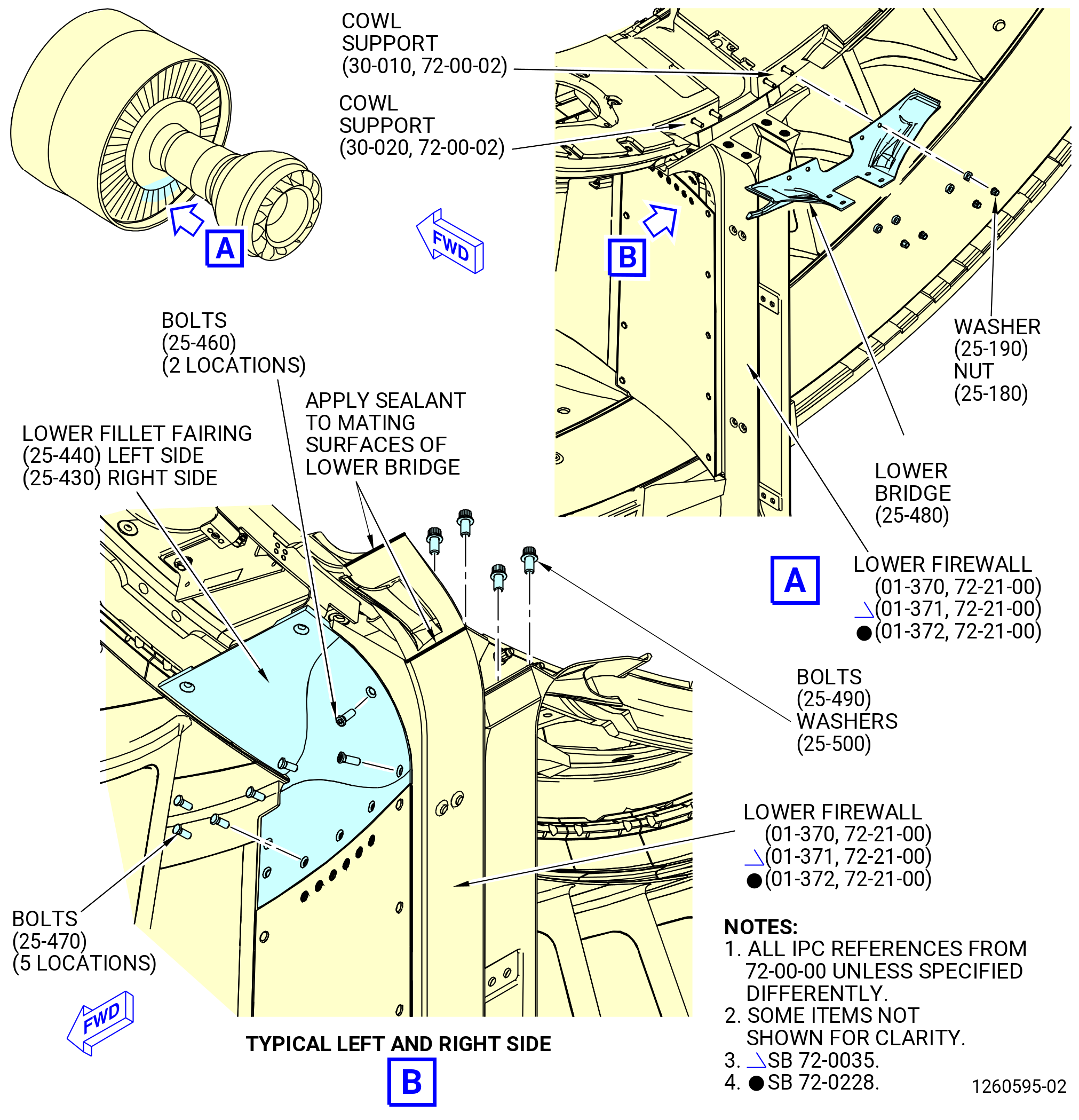
| I. | Install the lower bifurcation bridge (lower bridge) (25-480 , 72-00-00) and the lower fillet fairings (84506, 84507) as follows. Refer to Figure 410. |
| (1) | Lubricate the threads of four bolts (25-490 , 72-00-00), four studs on the cowl supports (30-010 , 72-00-02, 30-020 , 72-00-02), and four nuts (95040) with C02-058 graphite. |
| WARNING: |
|
| (2) | Clean the lower bridge (25-480 , 72-00-00) with C04-035 isopropyl alcohol. |
| (3) | Install the lower bridge to the aft side of the fan hub frame at the 6:00 o'clock position with four nuts (95040) and four washers (95030). Do not torque the nuts. |
| (4) | Attach the lower bridge to the lower firewall (01-370 , 72-21-00) (SIN 84501) or (01-371 , 72-21-00) (SIN 84501) or (01-372 , 72-21-00) (SIN 84501) with four bolts (25-490 , 72-00-00) (SIN 84526) and four washers (25-500 , 72-00-00) (SIN 84531). |
| NOTE: |
|
| (5) | Torque the bolts (25-490 , 72-00-00) to 106-124 lb in. (12.0-14.0 N.m). |
| (6) | Torque the nuts (95040) to 69-81 lb in. (7.8-9.2 N.m). |
| (7) | Lubricate the threads of ten bolts (84524), four screws (84525), and four bolts (8442G) with C02-058 graphite. |
| (8) | Install the fillet fairing (84507) to the left side of the lower bridge with five bolts (84524), two screws (84525) and two bolts (8442G). |
| (9) | Install the fillet fairing (84506) to the right side of the lower bridge with five bolts (84524), two screws (84525) and two bolts (8442G). |
| (10) | Deleted. |
| * * * END PRE SB 72-0050 |
| Subtask 72-00-01-420-069 |
| * * * SB 72-0050 |
| I.A. | Install the lower bifurcation bridge (lower bridge) (25-481 , 72-00-00) and the lower fillet fairings (84506, 84507) as follows. Refer to Figure 410. |
| (1) | Lubricate the threads of four bolts (25-491 , 72-00-00), four studs on the cowl supports (30-011 , 72-00-02, 30-021 , 72-00-02), and four nuts (95040) with C02-058 graphite. |
| WARNING: |
|
| (2) | Clean the lower bridge (25-481 , 72-00-00) with C04-035 isopropyl alcohol. |
| (3) | Install the lower bridge to the aft side of the fan hub frame at the 6:00 o'clock position with four nuts (95040) and four washers (95030). Do not torque the nuts. |
| (4) | Attach the lower bridge to the lower firewall (01-370 , 72-21-00) (SIN 84501) or (01-371 , 72-21-00) (SIN 84501) or (01-372 , 72-21-00) (SIN 84501) with four bolts (25-491 , 72-00-00) (SIN 84526) and four washers (25-500 , 72-00-00) (SIN 84531). |
| NOTE: |
|
| (5) | Torque the bolts (25-491 , 72-00-00) to 106-124 lb in. (12.0-14.0 N.m). |
| (6) | Torque the nuts (95040) to 69-81 lb in. (7.8-9.2 N.m). |
| (7) | Lubricate the threads of ten bolts (84524), four screws (84525), and four bolts (8442G) with C02-058 graphite. |
| (8) | Install the fillet fairing (84507) to the left side of the lower bridge with five bolts (84524), two screws (84525) and two bolts (8442G). |
| (9) | Install the fillet fairing (84506) to the right side of the lower bridge with five bolts (84524), two screws (84525) and two bolts (8442G). |
| (10) | Deleted. |
| * * * END SB 72-0050 |
| Subtask 72-00-01-420-011 |
| (11) | Install the lower bifurcation assembly. Refer to TASK 72-00-03-420-802 (72-00-03, INSTALLATION 001). |
|
|
| Subtask 72-00-01-420-012 |
| (12) | Apply C01-007 RTV to the lower bridge as follows. Refer to Figure 410. |
| WARNING: |
|
| (a) | Clean the lower bridge and the adjacent surfaces with C04-035 isopropyl alcohol. |
| (b) | Apply C01-007 RTV to the transition areas where the lower bridge touches other surfaces. Make sure that there is a smooth transition of the sealant between mating components. |
| NOTE: |
|
| (c) | Apply C01-007 RTV to the gap located above the cable bulkhead on the lower bifurcation module assembly on the right and left sides. |
| (d) | Let the C01-007 RTV cure for 12 hours. |
| Subtask 72-00-01-420-013 |
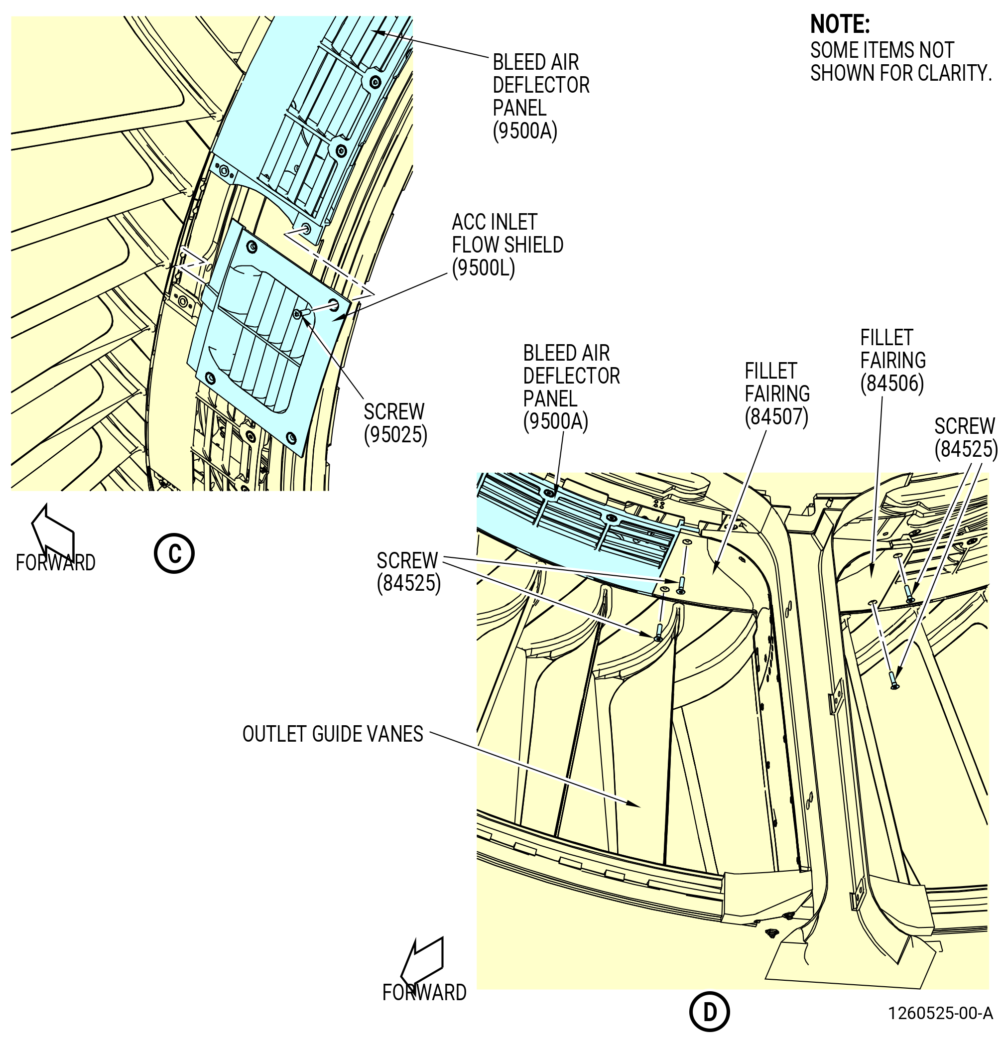
| J. | Install the VBV panels as follows. Refer to Figure 411. |
| (1) | Lubricate the threads of 52 machine screws (95025) and the eight fairing screws (four 84428, four 84525) with C02-058 graphite. |
| (2) | Install the bleed air deflector panels (deflector panels) (9500A) as follows: |
| NOTE: |
|
| CAUTION: |
|
| (a) | Loosely install one deflector panel (9500A) at the 1:00 o'clock, 5:00 o'clock, 7:00 o'clock, and 11:00 o'clock positions aft looking forward (ALF). Refer to Figure 411 for the installation pattern. |
| NOTE: |
|
| (b) | Insert the forward edge of the deflector panel into the groove below the trailing edge of the outlet guide vanes. Two holes in the center of the aft side of the deflector panel will be aligned with the nut plate holes in the deflector panel support segments (95010, 95011, 95012, 95013). |
| (c) | Insert two screws (95025) through the holes in the center of the aft side of the deflector panel and into the deflector panel support segment. |
| (d) | Install four screws (84428) near 12:00 o'clock position where the fillet fairings (84407, 8440A) overlap the deflector panels. |
| (e) | Install four screws (84525) near 6:00 o'clock position where the fillet fairings (84506, 84507) overlap the deflector panels. |
| (f) | Loosely install one deflector panel at the 2:00 o'clock, 3:00 o'clock, 4:00 o'clock, 8:00 o'clock, 9:00 o'clock, and 10:00 o'clock positions. |
| (g) | Insert the forward edge of the deflector panel into the groove below the trailing edge of the outlet guide vanes. Two holes in the center of the aft side of the deflector panel will be aligned with the nut plate holes in the deflector panel support segments (95010, 95011, 95012, 95013). |
| (h) | Install two screws (95025) in the holes in the center of the aft edge of each deflector panel. |
| (3) | Install the blankoff panels (9500B, 9500D) as follows: |
| (a) | Align three blankoff panels (9500B) at the 2:30 o'clock, 3:30 o'clock, and 8:30 o'clock positions, ALF, so that they overlap two deflector panels. |
| (b) | Insert the leading edge of the blankoff panels (9500B) into the groove beneath the trailing edge of the outlet guide vanes. |
| (c) | Make sure that the holes of the blankoff panels (9500B) are aligned with the holes in the deflector panels. |
| (d) | Attach each blankoff panel (9500B) to the deflector panels with four screws (95025). |
| (e) | Align four blankoff panels (9500D) at the 1:30 o'clock, 4:30 o'clock, 7:30 o'clock, and 10:30 o'clock positions ALF so that they overlap two deflector panels. |
| (f) | Insert the leading edge of the blankoff panels (9500D) into the groove below the trailing edge of the outlet guide vanes. |
| (g) | Make sure that the holes of the blankoff panels (9500D) are aligned with the holes in the deflector panels. |
| (h) | Attach each blankoff panel (9500D) to the deflector panels with four screws (95025). |
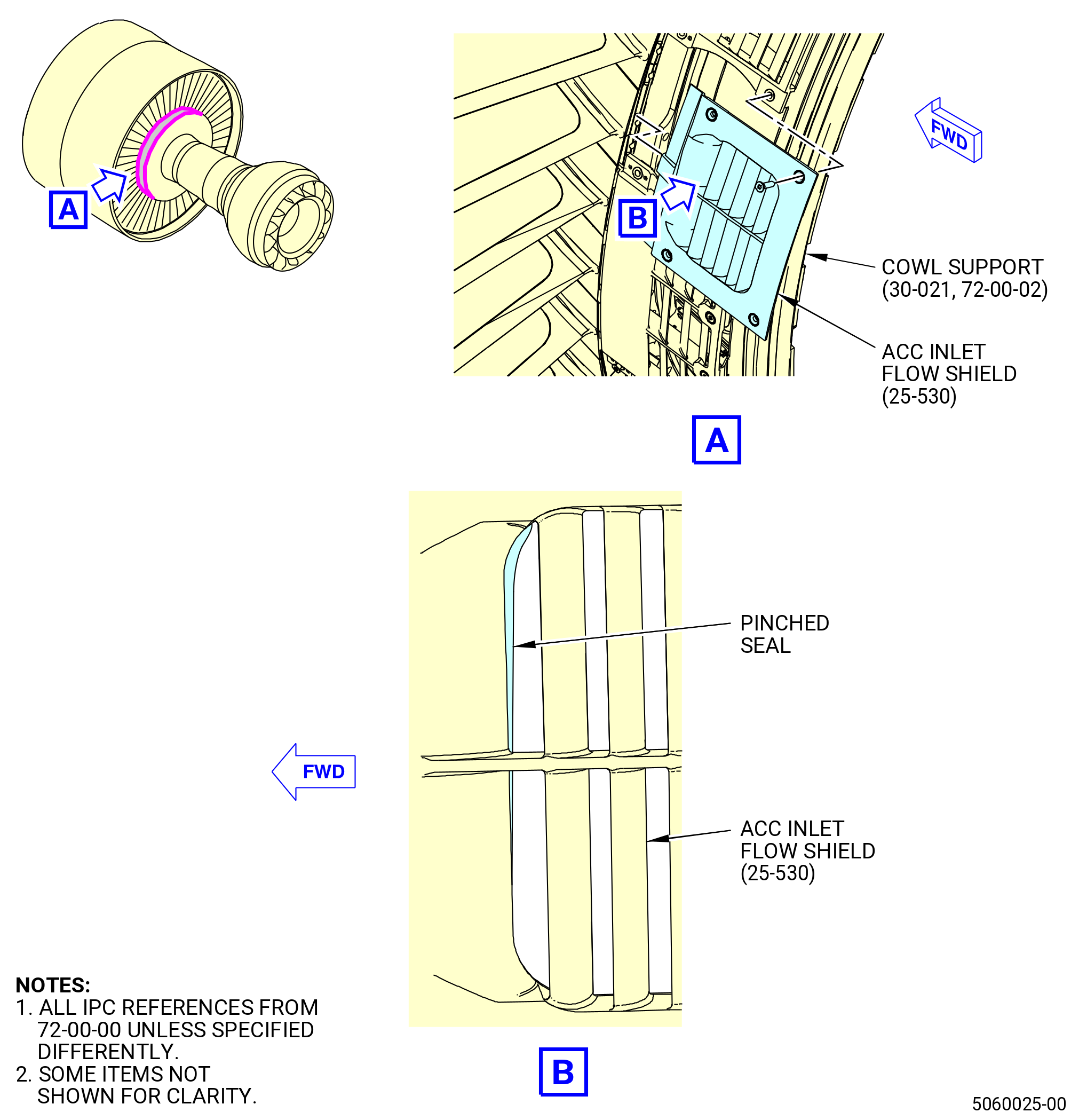
| (4) | Install the ACC inlet flow shield (flow shield) (9500L) as follows: |
| NOTE: |
|
| NOTE: |
|
| (a) | Align the flow shield (9500L) at the 9:30 o'clock position aft looking forward (ALF) so that it overlaps two deflector panels. |
| (b) | Insert the leading edge of the flow shield into the groove beneath the trailing edge of the outlet guide vanes. |
| (c) | Make sure that the holes of the flow shield are aligned with the holes in the deflector panels. |
| (d) | Attach the flow shield to the deflector panels with four screws (95025). |
| (5) | Torque the 10 bolts (25-470 , 72-00-00) (SIN 84524), 10 bolts (25-130 , 72-00-00) (SIN 84427), four bolts (25-460 , 72-00-00) (SIN 8442G), four bolts (25-140 , 72-00-00) (SIN 8442H), four screws (25-120 , 72-00-00) (SIN 84428), four screws (25-450 , 72-00-00) (SIN 84525), and the 52 machine screws (25-510 , 72-00-00) (SIN 95025) to 60 to 70 lb in. (6.8 to 7.9 Nm) in an alternating pattern. Refer to Figure 413 and do as follows: |
| NOTE: |
|
| (a) | Torque in an identified sequence. |
| (b) | Torque the left and right/upper and lower panels in the same sequence. |
| (6) | Do a 360-degree torque inspection of 10 bolts (25-470 , 72-00-00) (SIN 84524), 10 bolts (25-130 , 72-00-00) (SIN 84427), four bolts (25-460 , 72-00-00) (SIN 8442G), four bolts (25-140 , 72-00-00) (SIN 8442H), four screws (25-120 , 72-00-00) (SIN 84428), four screws (25-450 , 72-00-00) (SIN 84525), and the 52 machine screws (25-510 , 72-00-00) (SIN 95025) to 60 to 70 lb in. (6.8 to 7.9 Nm). |
| Subtask 72-00-01-420-076 |
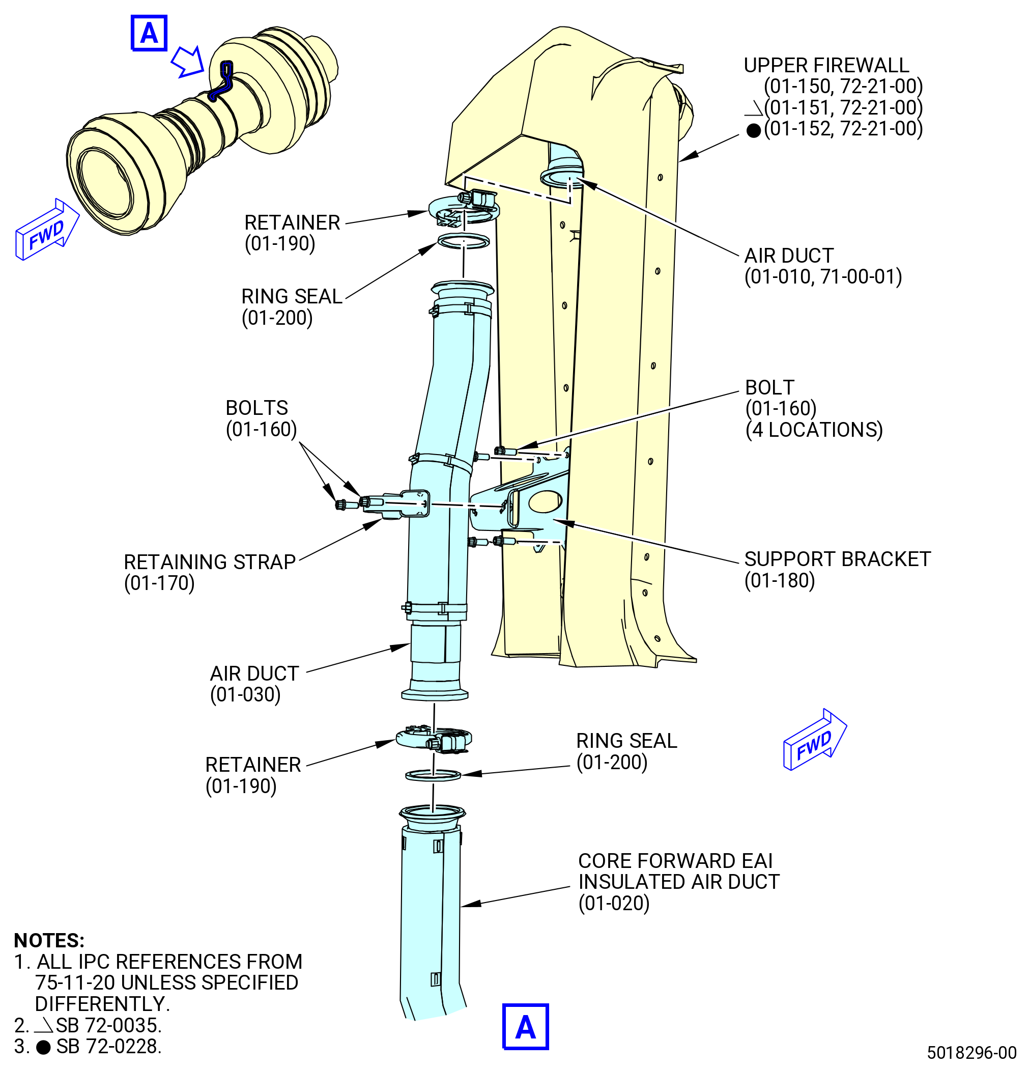
| K. | Install the air duct (01-030 , 75-11-20) (SIN 61004) on the core forward EAI insulated air duct (01-020 , 75-11-20) (SIN 61002). Refer to Figure 414 and do as follows: |
| (1) | Install the retainer V coupling (retainer) (01-190 , 75-11-20) (SIN 61081) on the lower side of the air duct. Do not tighten the retainer bolt at this time. |
| (2) | Install one ring seal (01-200 , 75-11-20) (SIN 61051) on the core forward EAI insulated air duct. |
| (3) | Align the air duct with the ring seal and the core forward EAI insulated air duct. |
| (4) | Adjust the retainer to connect the lower side of the air duct on the core forward EAI insulated air duct. |
| (5) | Torque the retainer bolt to 106-124 lb in. (12.0-14.0 N.m). |
| Subtask 72-00-01-420-014 |
| L. | Install the stage 1 blade shims (shims) (83071) to the fan rotor disk (830A0) as follows. Refer to Figure 415. |
| WARNING: |
|
| CAUTION: |
|
| (1) | Use C04-035 isopropyl alcohol to clean the disk slots and posts of the stage 1 disk, and the forward end of the booster drum. |
| (2) | Find the 18 shims. Do a visual inspection of each shim for bends or wrinkles. |
| CAUTION: |
|
| (3) | Wear C10-140 gloves and install each shim over each disk post with the FWD mark facing forward. |
| NOTE: |
|
| (4) | Make sure that all barrel nuts are installed at this time. |
| (5) | Make sure each shim is pushed fully aft on the fan rotor disk posts to prevent damage during retainer installation. |
| Subtask 72-00-01-420-015 |
| M. | Prepare the Stage 1 Fan Blades (fan blades) (83004) for installation as follows: |
| WARNING: |
|
| (1) | Use C04-035 isopropyl alcohol to clean the two sides of each of the 18 shims (83071) previously installed, 18 spacers (83008), and the two sides of the fabric coating on the root of the fan blade dovetails. |
| (2) | Let the fan blade roots dry, then apply C10-013 compound, release agent or C10-215 release agent (10 percent PTFE paint on dry film lubricant) to all the fabric coating dovetail surface areas. Stir the solution as it is applied to make sure that the lubricant is thoroughly mixed. |
| (3) | Apply a total of four coats of dry film lubricant to the fan blade root fabric. |
| NOTE: |
|
| (4) | Let the lubricant dry for approximately 20 minutes. |
| (5) | Make sure that the fan blade root areas are completely covered with lubricant. |
| NOTE: |
|
| Subtask 72-00-01-420-065 |
| N. | Apply dry film lubricant to the large, flat surfaces of the fan blade spacer as follows: |
| (1) | Apply C10-013 compound, release agent or C10-215 release agent to the entire spacer except for the end block. Stir the solution as it is applied to make sure the lubricant is thoroughly mixed. |
| NOTE: |
|
| (2) | Apply a total of four coats of dry film lubricant to the spacer not allowing it to dry between applications. |
| (3) | Let the lubricant dry for approximately 20 minutes and make sure the spacer is completely covered by doing a visual inspection for residual white powder. |
| Subtask 72-00-01-420-016 |
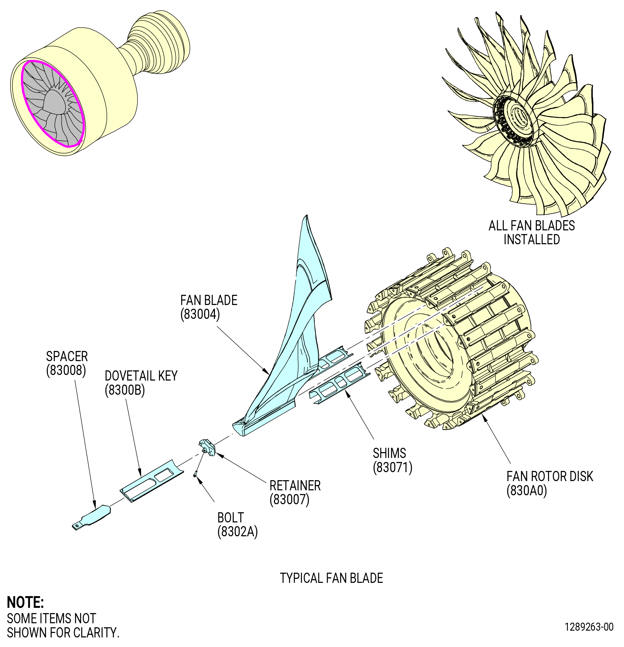
| O. | Install the 18 stage 1 fan blades (fan blades) (83004) as follows. Refer to Figure 415. |
| (1) | Put the 18 stage 1 fan blades in sequence, by their individual radial moment-weight, from the heaviest to the lightest blade. |
| NOTE: |
|
| Subtask 72-00-01-430-562 |
| (2) | Alternative Procedure Available. Number the fan blades (83004) in ascending sequence (1 to 18) from the heaviest to the lightest as follows: |
| (a) | Put a piece of C10-021 tape (yellow tape recommended) on each fan blade. |
| (b) | Mark with a C05-003 pen on the tape that was put on the fan blades. |
| (c) | Put a number 1 on the heaviest fan blade and continue the number sequence until the lightest blade is identified with a number 18. |
| Subtask 72-00-01-420-066 |
| (2).A. | Alternative Procedure. Identify the fan blade sequence by plotting fan blades (83004) using software as follows: |
| (a) | Put a piece of C10-021 tape (yellow tape recommended) on each fan blade. |
| (b) | Mark with a C05-003 pen on the tape that was put on the fan blades 1 through 18 to identify current blade sequence. |
| (c) | Enter all fan blade radial moment weights in order, from 1 through 18, into the 9446M61 mapping program. |
| (d) | Using the 9446M61 mapping program results, strike the current number and re-sequence the fan blades using a C05-003 pen, 1 through 18, on the tape that was put on the fan blades. |
| NOTE: |
|
| (3) | Put the fan blades in their correct location on the fan disk as follows: |
| (a) | The fan disk slot locations for the fan blades are given in a counterclockwise (CCW) direction, forward looking aft (FLA). |
| (b) | A number 1 is stamped on each side of the number 1 fan disk slot on the forward face of the fan disk. |
| 1 | This is to identify the position for the installation of the fan blade number 1. |
| (c) | A number 5 is stamped on the forward face of the fan disk at the number 5 fan disk slot location. |
| 1 | This gives the CCW reference direction for fan blade installation. |
| 2 | Start with the number 1 fan blade slot and count in a CCW direction to find the number 5 fan disk slot. |
| Subtask 72-00-01-420-067 |
| (4) | Install the fan blade set as follows : |
| (a) | Make sure that the fan blade shims (83071) are installed fully aft before the fan blades are installed. |
| (b) | Install the No. 1 fan blade into the No. 1 dovetail slot. |
| (c) | Install the stage 1 retainer (83007) into the parts with recesses of the disk post in front of the fan blade. |
| (d) | Install the dovetail key (8300B) into the aft-most center position of the dovetail slot. |
| (e) | Apply the C10-215 release agent (10% PTFE paint on dry film lubricant) to the large, flat surfaces of the fan blade spacer (83008) as follows: |
| NOTE: |
|
| 1 | Apply C10-215 release agent (10% PTFE paint on dry film lubricant) to the entire spacer. Stir the solution as it is applied to make sure the lubricant is thoroughly mixed. |
| 2 | Apply a total of four coats of dry film lubricant C10-215 release agent to the spacer. Do not permit it to dry between applications. |
| 3 | Let the lubricant dry for approximately 20 minutes and make sure that the spacer is completely covered by doing a visual inspection for residual white powder. |
| NOTE: |
|
| (f) | Look inside the hub and down to make sure that the spacer is in the grooved slot of the dovetail key axially aligned with the center of the blade post. |
| (g) | Lubricate the threads of bolt (8302A) with C02-058 graphite and attach the spacer to the retainer with the bolt (8302A). |
| (h) | Torque the bolt to 106-124 lb in. (12-14 N.m). |
| (i) | Install the remaining fan blades. Repeat the Subtask 72-00-01-420-067 (paragraph 3.N.(5).(b).) thru (paragraph 3.N.(5).(h)). |
| Subtask 72-00-01-420-017 |
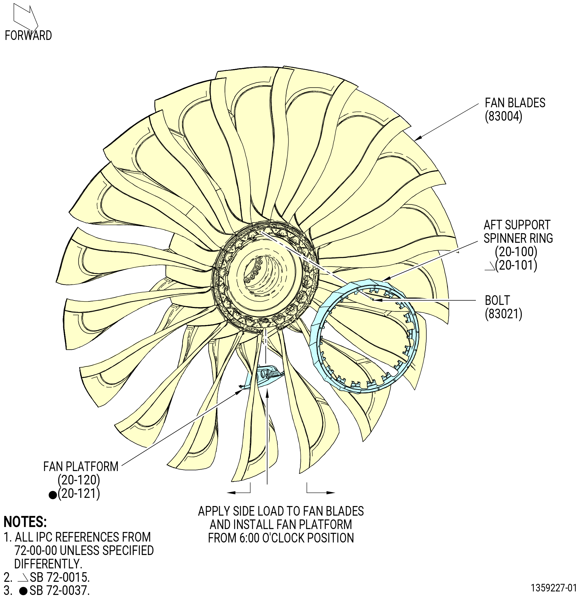
| P. | Make a plot of the fan platforms (20-120 , 72-00-00) (SIN 83005) or (20-121 , 72-00-00) (SIN 83005) and record the imbalance as follows: |
| (1) | Use a digital scale and record the mass and serial number of each fan platform. |
| (2) | Enter this information into the computer program. |
| (3) | Print out a copy and save this information. |
| NOTE: |
|
| Subtask 72-00-01-420-109 |
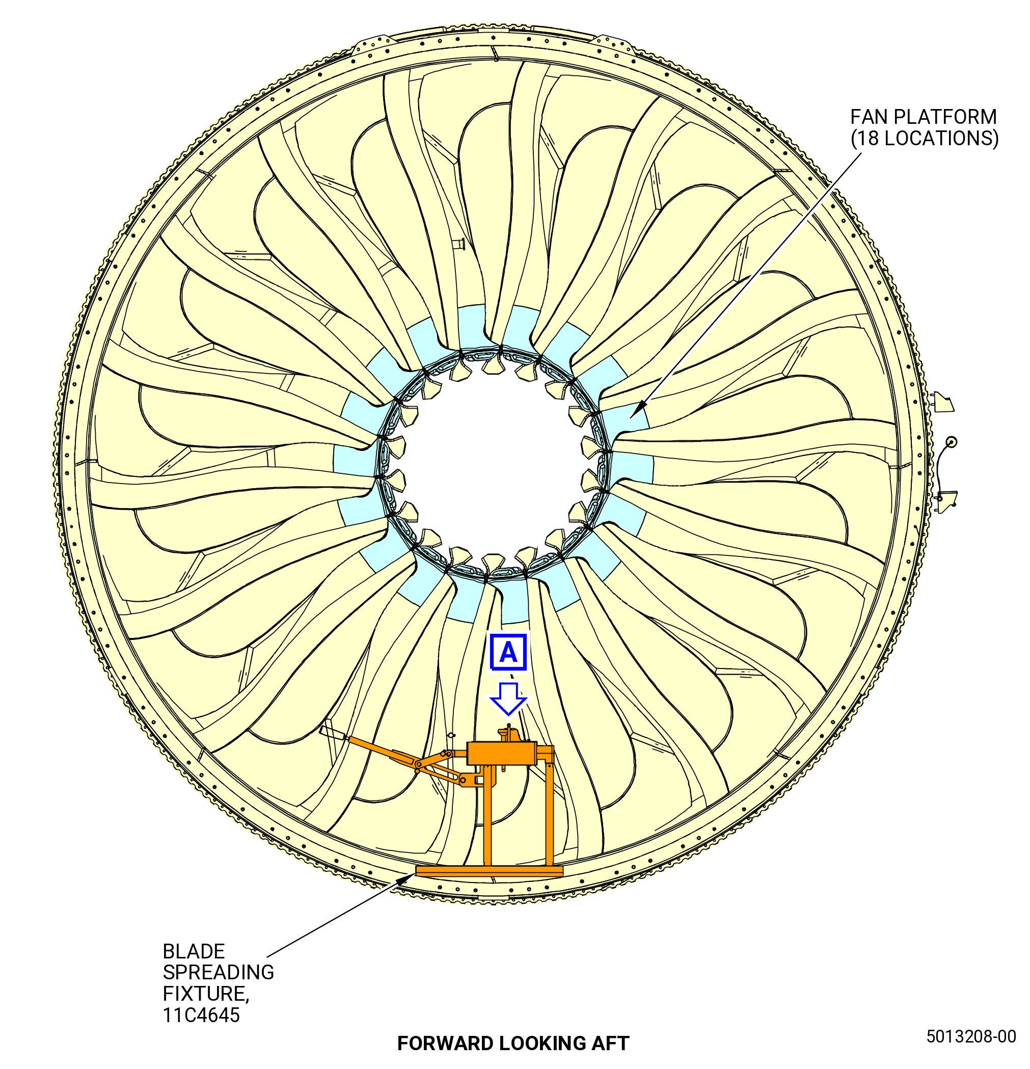
| Q. | Alternative Procedure Available. Install the fan platforms (20-120 , 72-00-00) (SIN 83005) or (20-121 , 72-00-00) (SIN 83005) with the 11C4645 blade spreading fixture. Refer to Figure 416 and do as follows: |
| (1) | Do a visual inspection of the inside of each fan platform (20-120 , 72-00-00) (SIN 83005) or (20-121 , 72-00-00) (SIN 83005) for unwanted objects, such as carbon plugs from the manufacturing drilling process. |
| (2) | Slowly turn the fan blades until the No. 1 fan blade is at the 6:00 o'clock position. Manually push on the root of the fan blades to turn the fan disk. |
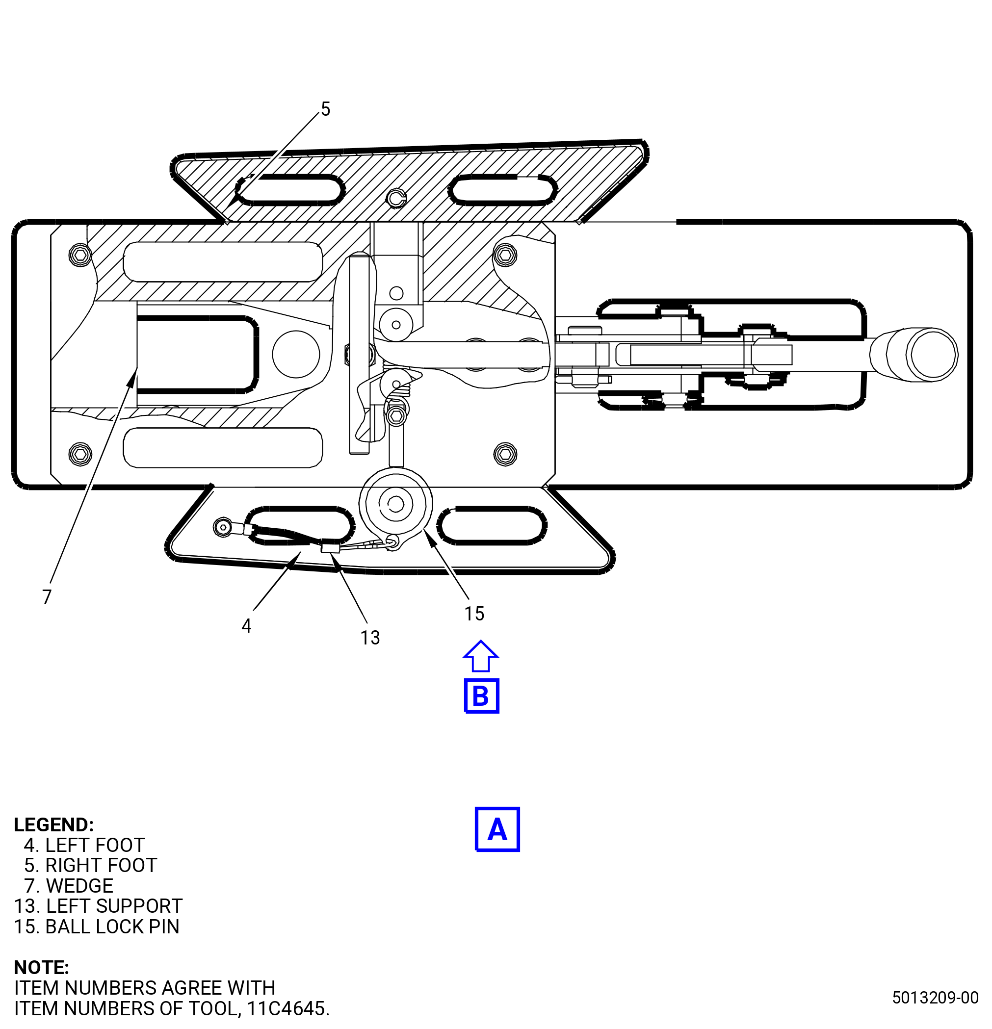
| (3) | Prepare the 11C4645 blade spreading fixture for use. Refer to Figure 416 and do as follows: |
| (a) | Align the left foot (item 4) hole with the left support (item 13) hole that has the GENX-1B mark. |
| (b) | Put the ball lock pin (item 15) through the two holes. |
| WARNING: |
|
| (4) | Carefully lift the 11C4645 blade spreading fixture with the handle (item 14) and put it between the fan blades so it rests on the base (item 10) on the inside surface of the fan case. |
| (5) | Use the left hand to pull the arm (item 8) down with the lever arm (item 20) while putting the right hand on the base (item 10) to balance the 11C4645 blade spreading fixture. |
| NOTE: |
|
| (6) | Pull the arm (item 8) until the mark OPEN in the wedge (item 7) is exposed. |
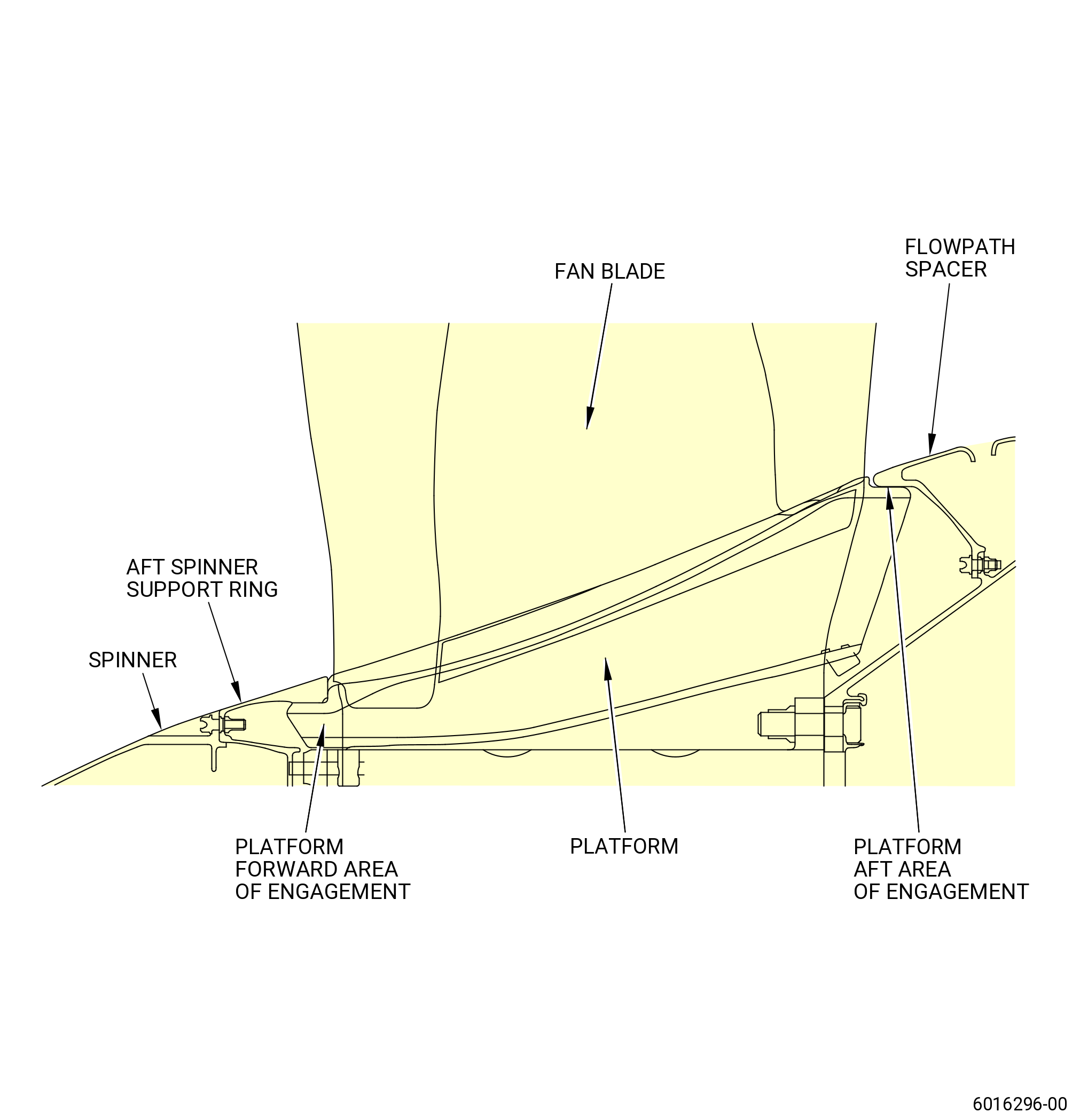
| (7) | Refer to the fan platform plot sheet and install fan platform No. 1 between the No. 1 and No. 2 fan blades. Make sure that the aft end of the fan platform (20-120 , 72-00-00) (SIN 83005) or (20-121 , 72-00-00) (SIN 83005) is under the flowpath spacer (01-060 , 72-22-00) (SIN 830AM) of the fan booster assembly (20-010 , 72-00-02) (SIN 80000). |
| (8) | Pull the arm (item 8) up with the lever arm (item 20) until the left foot (item 4) and the right foot (item 5) are fully contracted, putting the fan blades back into the original position. |
| CAUTION: |
|
| (9) | Apply C10-021 tape from the fan blade side to the top of each fan platform (20-120 , 72-00-00) (SIN 83005) or (20-121 , 72-00-00) (SIN 83005) to make sure that the fan platform does not fall. |
| (10) | Use the handle (item 14) to lift and remove the 11C4645 blade spreading fixture. |
| (11) | Refer to Subtask 72-00-01-420-109 (paragraph 3.Q.(4) thru paragraph 3.Q.(10)) to install the fan platform No. 2 between the No. 2 and No. 3 fan blades. |
| (12) | Continue to install the fan platforms in numerical sequence until all 18 fan platforms are installed. |
| Subtask 72-00-01-420-018 |
| Q.A. | Alternative Procedure. Install the fan platforms (20-120 , 72-00-00) (SIN 83005) or (20-121 , 72-00-00) (SIN 83005). Refer to Figure 417 and do as follows: |
| NOTE: |
|
| (1) | Do a visual inspection of the inside of each fan platform for foreign objects. |
| (2) | Slowly turn the fan blades until the No. 1 fan blade is at the 6:00 o'clock position. Manually push on the root of the fan blades to turn the fan disk. |
| (3) | Refer to the fan platform plot sheet and install fan platform No. 1, between the No. 1 and No. 2 fan blades. |
| (4) | Install the number No. 2 fan platform between the No. 2 and No. 3 fan blades. |
| (5) | Continue to install the fan platforms in numerical order until all 18 fan platforms are installed. |
| Subtask 72-00-01-420-019 |
| * * * PRE SB 72-0015( Aft Support Spinner Ring One-Piece Design ) |
| R. | Install the aft support spinner ring (20-100 , 72-00-00) as follows. Refer to Figure 417. |
| CAUTION: |
|
| (1) | Assemble the aft support spinner ring to the fan hub disk until the 1-1 mark on the aft support spinner ring matches with the 1-1 mark on the fan rotor disk post. |
| (2) | Make sure that the offset hole on the aft support spinner ring aligns with the offset hole on the fan rotor disk post. |
| (3) | Lubricate the threads and mating surfaces of the 18 bolts (83021) with C02-058 graphite. |
| (4) | Install the 18 bolts (83021) and torque them to 79-93 lb in. (8.9-10.5 N.m) in a criss-cross pattern. |
| (5) | Torque bolts (83021) again to 106-124 lb in. (12-14 N.m) in a criss-cross pattern. |
| (6) | Loosen the bolts (83021) one half turn, then torque them again to 106-124 lb in. (12-14 N.m) in a criss-cross pattern. |
| (7) | Do a 360 degrees torque check to make sure that all bolts (83021) are 106-124 lb in. (12-14 N.m). |
| * * * END PRE SB 72-0015 |
| Subtask 72-00-01-420-070 |
| * * * SB 72-0015( Aft Support Spinner Ring Two-Piece Design ) |
| R.A. | Install the spinner assembly aft support ring (aft support spinner ring) (20-101 , 72-00-00) as follows. Refer to Figure 417. |
| CAUTION: |
|
| (1) | Assemble the aft support spinner ring to the fan hub disk until the 1-1 mark on the aft support spinner ring matches with the 1-1 mark on the fan rotor disk post. |
| (2) | Make sure that the offset hole on the aft support spinner ring aligns with the offset hole on the fan rotor disk post. |
| (3) | Lubricate the threads and mating surfaces of the 18 bolts (83021) with C02-058 graphite. |
| (4) | Install the 18 bolts (83021) and torque them to 79-93 lb in. (8.9-10.5 N.m) in a criss-cross pattern. |
| (5) | Torque bolts (83021) again to 106-124 lb in. (12-14 N.m) in a criss-cross pattern. |
| (6) | Loosen the bolts (83021) one half turn, then torque them again to 106-124 lb in. (12-14 N.m) in a criss-cross pattern. |
| (7) | Do a 360 degrees torque check to make sure that all bolts (83021) are 106-124 lb in. (12-14 N.m). |
| * * * END SB 72-0015 |
| Subtask 72-00-01-420-117 |
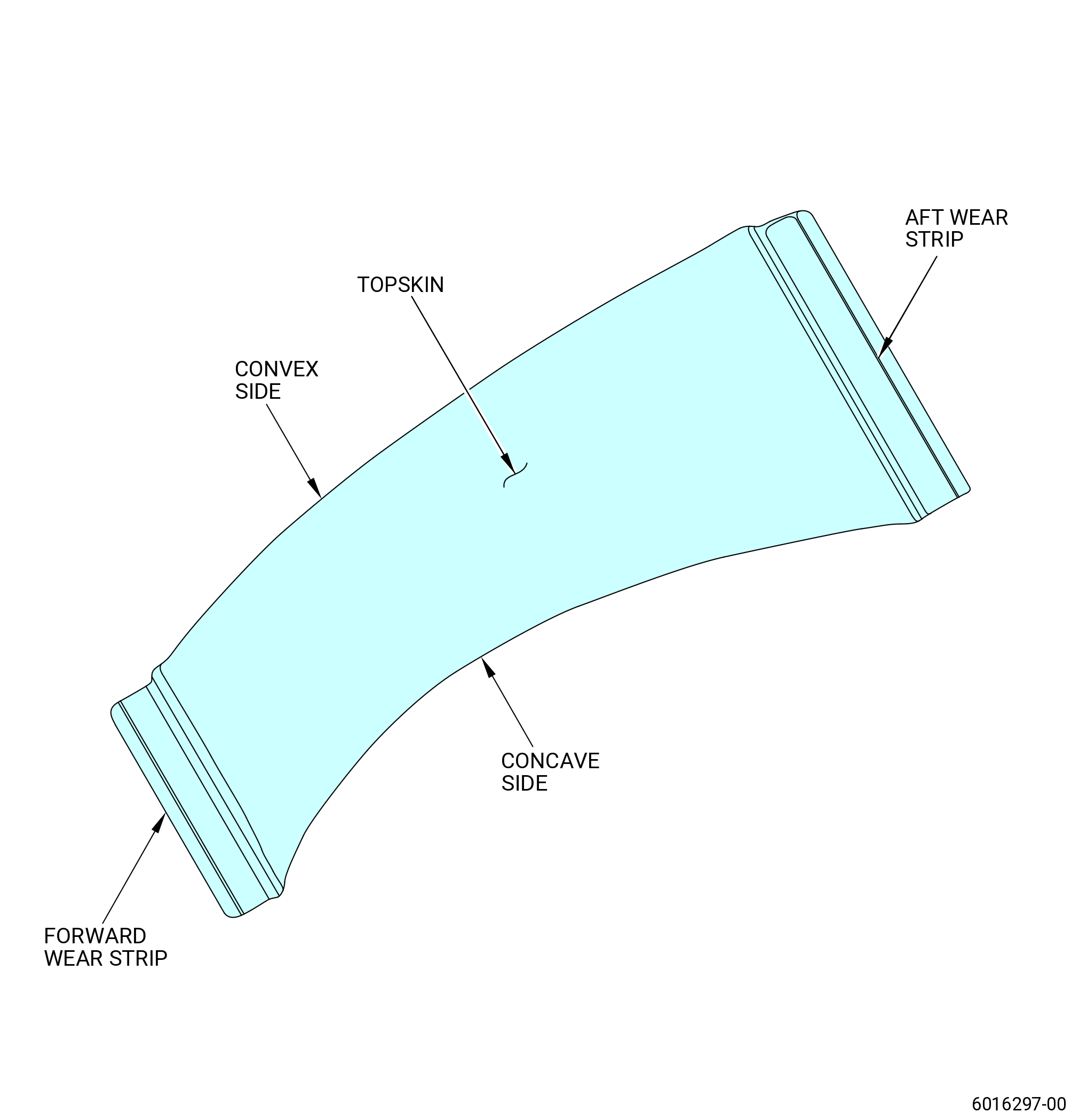
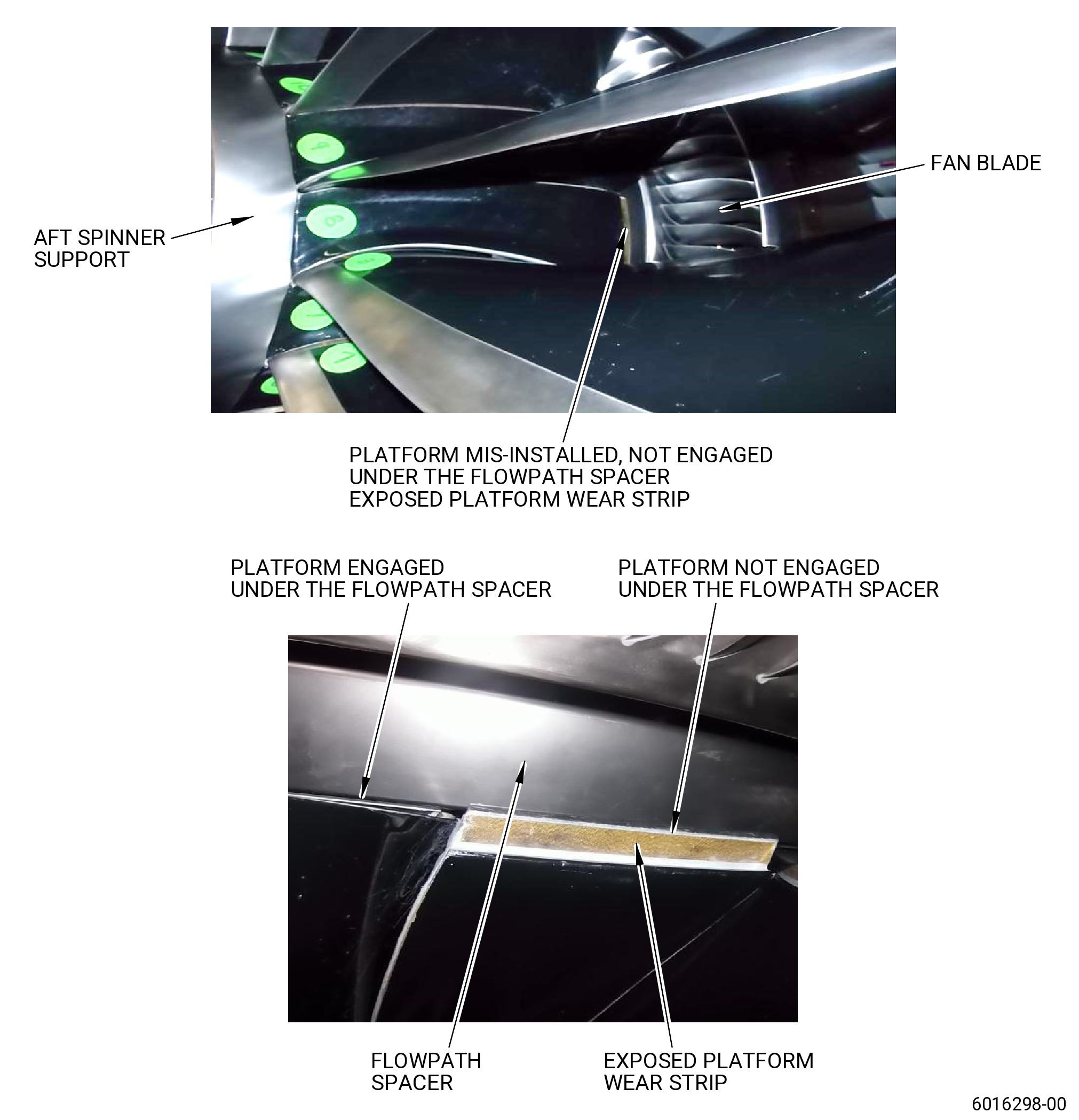
| S. | Verify proper platform installation by ensuring proper engagement under the aft spinner support and flowpath spacer. Exposed platform wear strips is an indication of improper platform installation. Refer to Figure 418. |
| Subtask 72-00-01-420-020 |
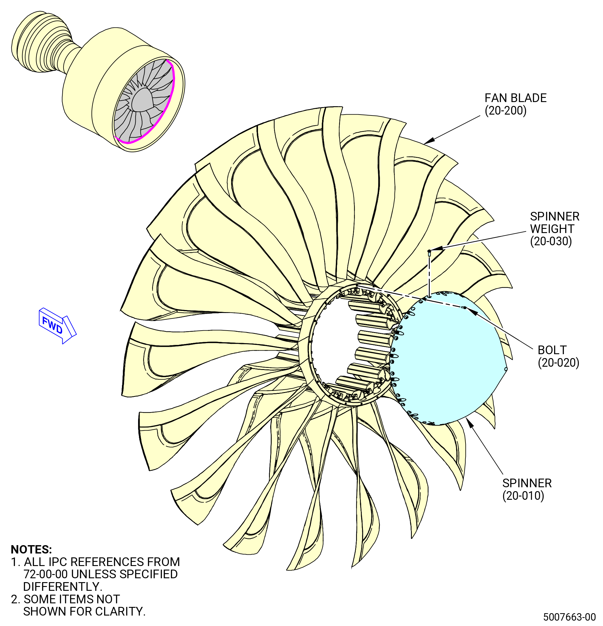
| T. | Install the fan rotor spinner (spinner) (83002) as follows. Refer to Figure 419. |
| (1) | Make sure that there is no foreign object damage (FOD) inside the fan hub, inside the aft support spinner ring (8300A), and inside the spinner (83002). |
| WARNING: |
|
| (2) | Clean the mating surfaces of the aft support spinner ring and the spinner with C04-035 isopropyl alcohol. |
| (3) | Lubricate the bolt balance weights (spinner weights) (83022) with C02-058 graphite. |
| NOTE: |
|
| (4) | Install the spinner weights (83022) onto the fan rotor spinner. |
| (5) | Torque the spinner weights to 155 lb in. (17.5 N·m). |
| WARNING: |
|
| (6) | Lubricate the threads and mating surfaces of the 18 machine bolts (bolts) (20-020 , 72-00-00) (SIN 8302C) with C02-058 graphite . |
| (7) | Align the 1-1 mark on the spinner (20-010 , 72-00-00) (SIN 83002) with the 1-1 mark on the aft support spinner ring (20-100 , 72-00-00) (SIN 8300A). Attach the spinner (20-010 , 72-00-00) (SIN 83002) with the 18 bolts (20-020 , 72-00-00) (SIN 8302C). |
| (8) | Torque the 18 bolts (20-020 , 72-00-00) (SIN 8302C) to 42-45 lb in. (4.8-5.0 N·m) in a criss-cross pattern. |
| (9) | Torque the 18 bolts (20-020 , 72-00-00) (SIN 8302C) again to 60-70 lb in. (6.8-7.9 N·m) in a criss-cross pattern. |
| (10) | Do a 360 degrees torque check on the 18 bolts (20-020 , 72-00-00) (SIN 8302C) to 60-70 lb in. (6.8-7.9 N·m). |
| (11) | Do a 360 degrees torque check of the spinner weights (83022) to 155 lb in. (17.5 N·m). |
| Subtask 72-00-01-420-023 |
| U. | Put the thrust reverse cross-tie brackets (25-010 , 71-00-02) (SIN 25015), (25-020 , 71-00-02) (SIN 25016), and the other TRF brackets (25-030 , 71-00-02) (SIN 25010), (25-040 , 71-00-02) (SIN 25011), (25-050 , 71-00-02) (SIN 25012), (25-060 , 71-00-02) (SIN 25014), and (25-070 , 71-00-02) (SIN 25019) in a large, clear plastic bag, and keep the bag with the engine hardware. |
| NOTE: |
|
| Subtask 72-00-01-420-024 |
| V. | Continue with the assembly of the engine. To assemble the fan stator case assembly (00109). Refer to TASK 72-00-01-430-803 (72-00-01, ASSEMBLY 001). |