| GENX-1B CLEANING,INSPECTION,AND REPAIR MANUAL | Dated: 12/06/2024 | |
| CIR 72-21-06 , INSPECTION 001 | ||
| FORWARD ENGINE MOUNT YOKE - INSPECTION | ||
| GENX-1B CLEANING,INSPECTION,AND REPAIR MANUAL | Dated: 12/06/2024 | |
| CIR 72-21-06 , INSPECTION 001 | ||
| FORWARD ENGINE MOUNT YOKE - INSPECTION | ||
| * * * FOR ALL |
| TASK 72-21-06-200-801 |
| 1 . | General. |
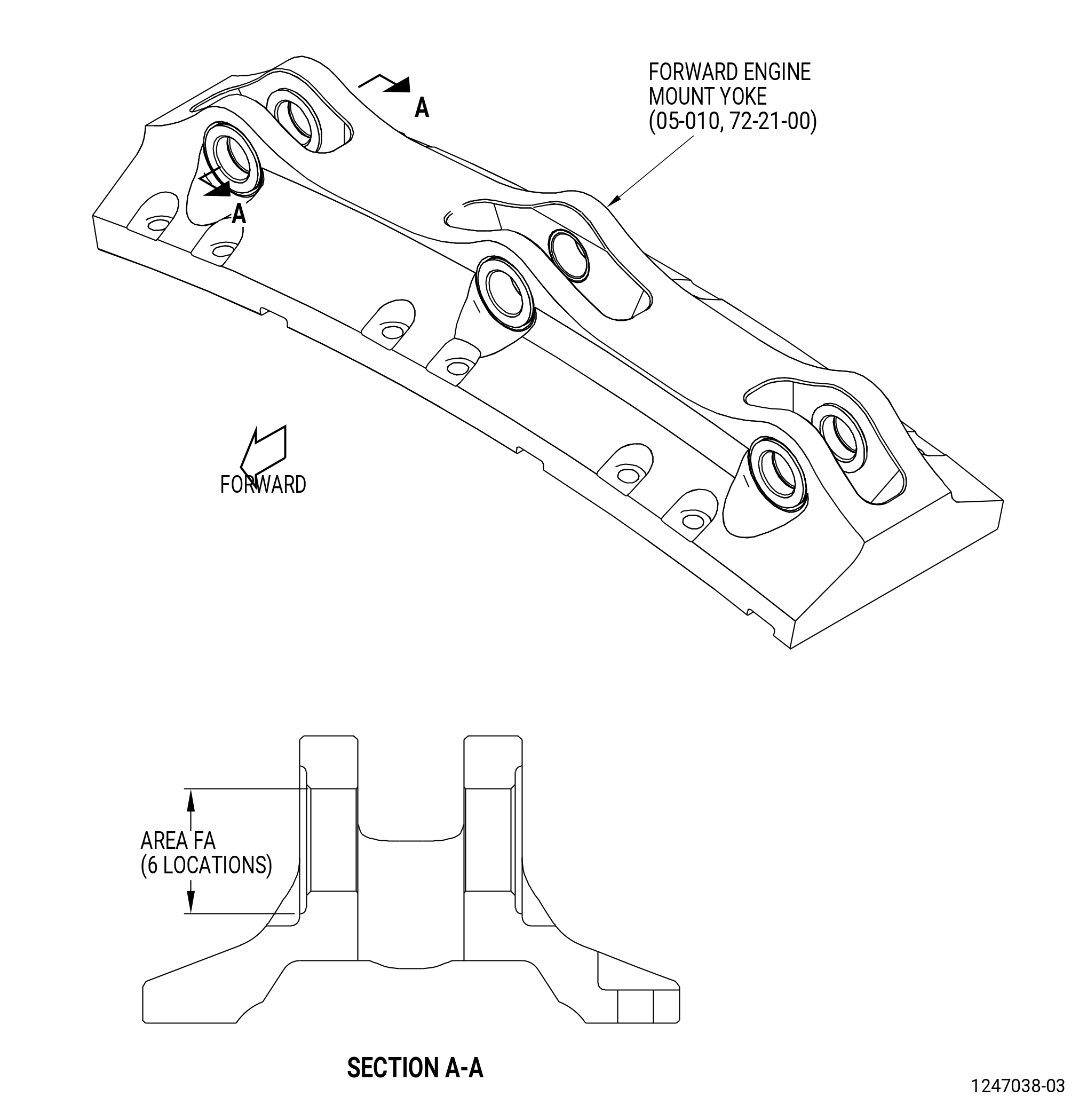
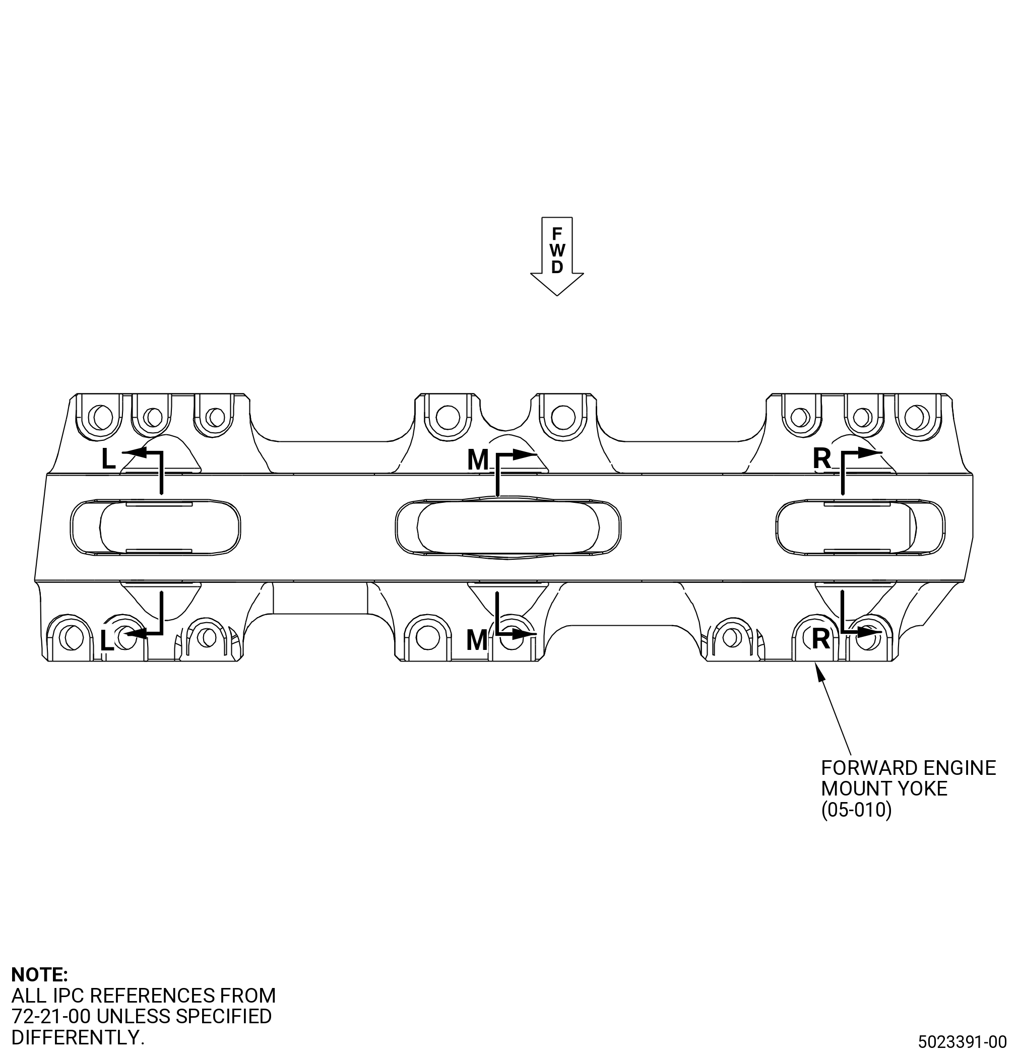
| A. | This procedure gives instructions to do an inspection of the forward engine mount yoke (05-010 , 72-21-00). |
| B. | If SB 72-0281 was applied, refer to TASK 72-00-01-200-801 (72-00-01, INSPECTION 001) . |
| 2 . | Tools, Equipment, and Materials. |
| NOTE: |
|
| A. | Tools and Equipment. |
| (1) | Special Tools. None. |
| (2) | Standard Tools and Equipment. None. |
| (3) | Locally Manufactured Tools. None. |
| B. | Consumable Materials. None. |
| C. | Referenced Procedures. |
|
| D. | Expendable Parts. None. |
| 3 . | Specific Inspection Procedure. |
| Subtask 72-21-06-230-001 |
| A. | Do a Class G fluorescent-penetrant inspection of the forward engine mount yoke for cracks as follows. Refer to TASK 70-32-02-230-001 (FLUORESCENT PENETRANT INSPECTION) and Figure 801 or Figure 801A. |
| (1) | Linear indications are not permitted. |
| NOTE: |
|
| (2) | Indications in area FA that are less than 0.015 inch (0.38 mm) in length and a minimum of 0.15 inch (3.8 mm) apart are permitted. |
| (3) | Indications in all other areas of the forward engine mount yoke that are less than 0.03 inch (0.8 mm) in length and a minimum of 0.15 inch (3.8 mm) apart are permitted. |
| 4 . | Visual Inspection. |
| Subtask 72-21-06-220-001 |
| A. | Do an inspection of the forward engine mount yoke as follows: |
| (1) | Cracks: |
| Maximum serviceable limit: |
|
| Repair method: |
|
| Subtask 72-21-06-220-002 |
| (2) | Nicks or scratches in clevis hole bores and edges: |
| Maximum serviceable limit: |
|
| Maximum repairable limit: |
|
| Repair method: |
|
| Subtask 72-21-06-220-018 |
| (3) | Nicks or scratches in bolthole (configuration 1 - 12 bolthole mount bolt configuration). Refer to Figure 801. |
| Maximum serviceable limit: |
|
| Maximum repairable limit: |
|
| Repair method: |
|
| Subtask 72-21-06-220-016 |
| (4) | Nicks or scratches in bolthole (configuration 2 - 16 bolthole mount bolt configuration). Refer to Figure 801A. |
| Maximum serviceable limit: |
|
| Maximum repairable limit: |
|
| Repair method: |
|
| Subtask 72-21-06-220-003 |
| (5) | Nicks in all other areas (configuration 1 - 12 bolthole mount bolt configuration). Refer to Figure 801. |
| Maximum serviceable limit: |
|
| Maximum repairable limit: |
|
| Repair method: |
|
| Subtask 72-21-06-220-017 |
| (6) | Nicks in all other areas (configuration 2 - 16 bolthole mount bolt configuration). Refer to Figure 801A. |
| Maximum serviceable limit: |
|
| Maximum repairable limit: |
|
| Repair method: |
|
| Subtask 72-21-06-220-004 |
| (7) | Scratches in all other areas: |
| Maximum serviceable limit: |
|
| Maximum repairable limit: |
|
| Repair method: |
|
| Subtask 72-21-06-220-005 |
| (8) | High metal on mating surfaces: |
| Maximum serviceable limit: |
|
| Maximum repairable limit: |
|
| Repair method: |
|
| Subtask 72-21-06-220-006 |
| (9) | Wear in the bushing boltholes: |
| Maximum serviceable limit: |
|
| Repair method: |
|
| Subtask 72-21-06-220-020 |
| (10) | Alternative Procedure Available. Bushing migration. Refer to Figure 802: |
| NOTE: |
|
| Maximum serviceable limit: |
|
| Repair method: |
|
| • |
|
| • |
|
| NOTE: |
|
| Subtask 72-21-06-220-021 |
| (10).A. | Alternative Procedure. Bushing migration. Refer to Figure 802: |
| NOTE: |
|
| Maximum serviceable limit: |
|
| Repair method: |
|
| Subtask 72-21-06-220-022 |
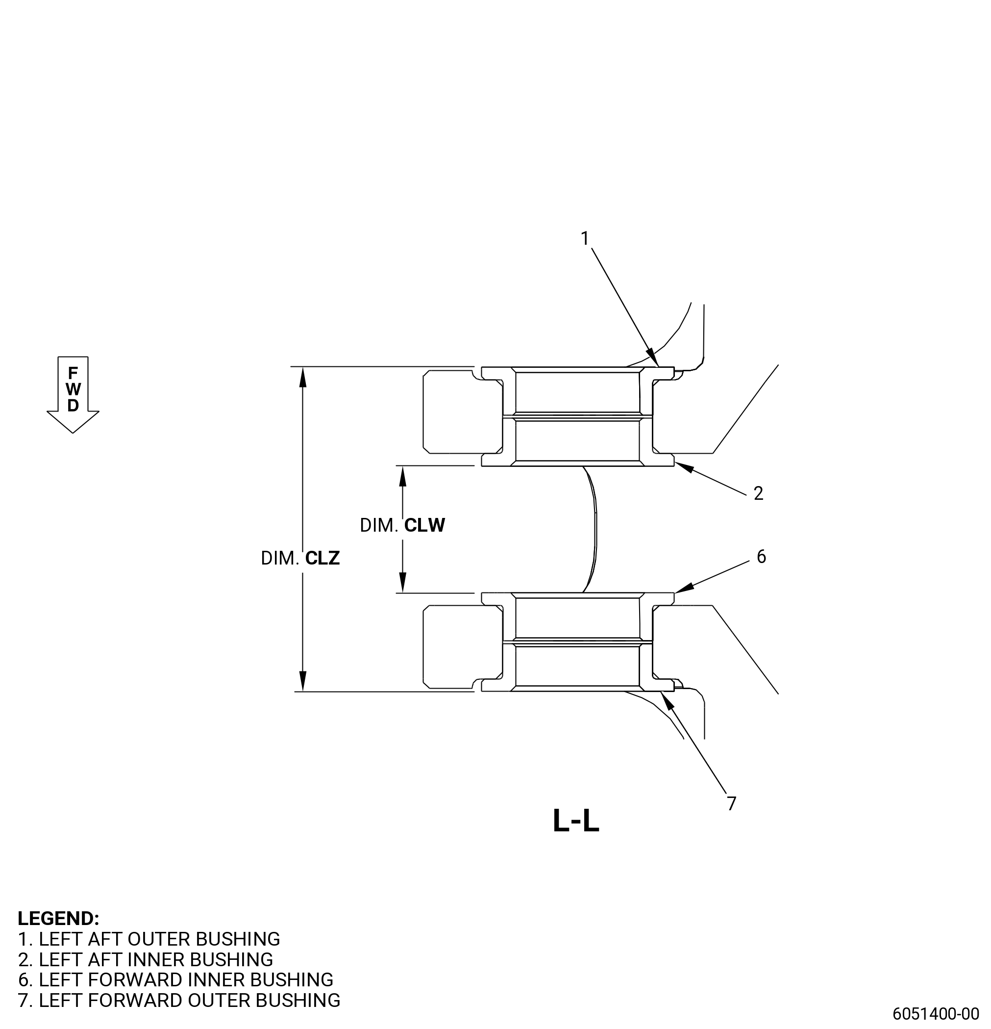
| (11) | Alternative Procedure Available. Dimension CLZ: |
| NOTE: |
|
| Maximum serviceable limit: |
|
| Repair method: |
|
| • |
|
| • |
|
| NOTE: |
|
| Subtask 72-21-06-220-023 |
| (11).A. | Alternative Procedure. Dimension CLZ: |
| NOTE: |
|
| Maximum serviceable limit: |
|
| Repair method: |
|
| Subtask 72-21-06-220-024 |
| (12) | Alternative Procedure Available. Dimension CLW: |
| NOTE: |
|
| Minimum serviceable limit: |
|
| Repair method: |
|
| • |
|
| • |
|
| NOTE: |
|
| Subtask 72-21-06-220-025 |
| (12).A. | Alternative Procedure. Dimension CLW: |
| NOTE: |
|
| Minimum serviceable limit: |
|
| Repair method: |
|
| Subtask 72-21-06-220-026 |
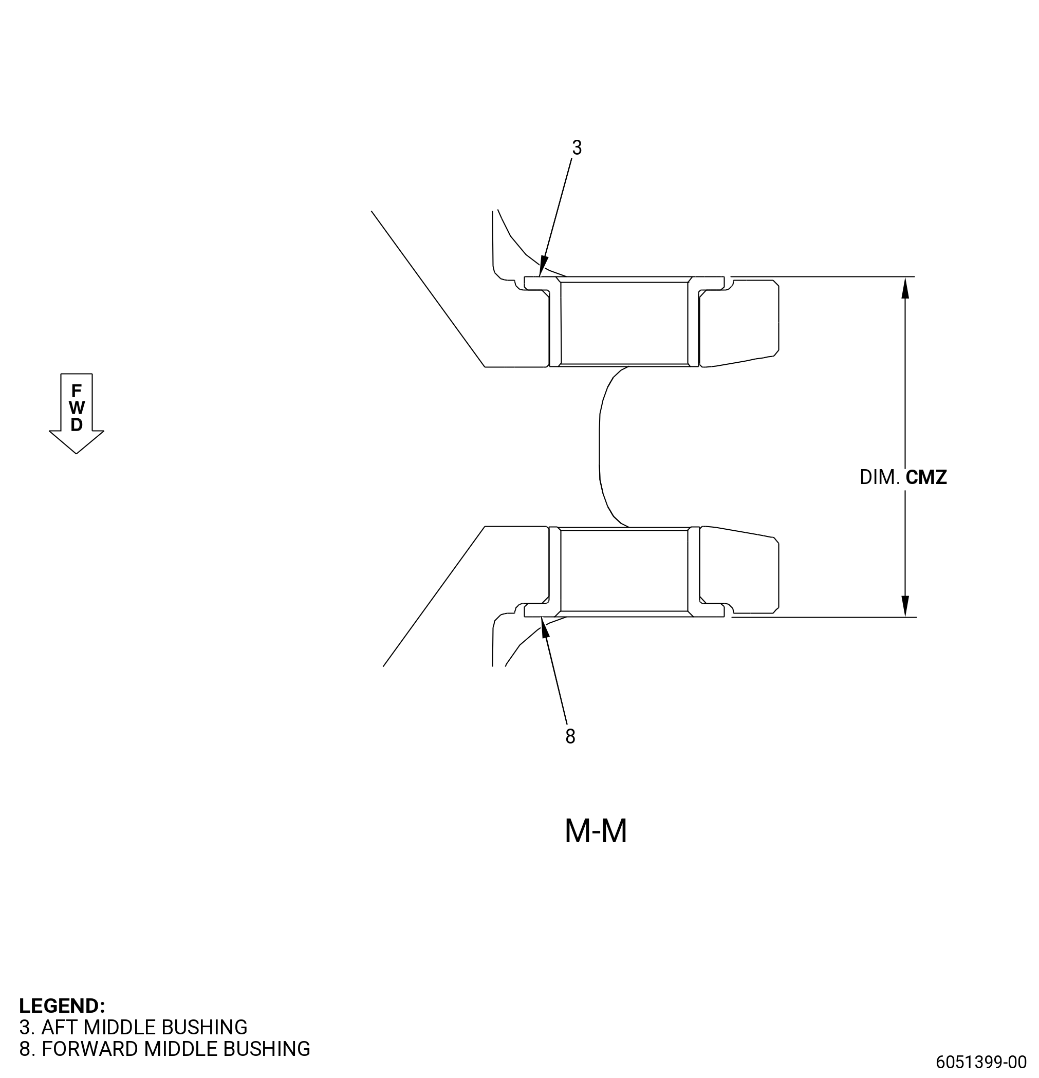
| (13) | Alternative Procedure Available. Dimension CMZ: |
| NOTE: |
|
| Maximum serviceable limit: |
|
| Repair method: |
|
| • |
|
| • |
|
| NOTE: |
|
| Subtask 72-21-06-220-027 |
| (13).A. | Alternative Procedure. Dimension CMZ: |
| NOTE: |
|
| Maximum serviceable limit: |
|
| Repair method: |
|
| Subtask 72-21-06-220-028 |
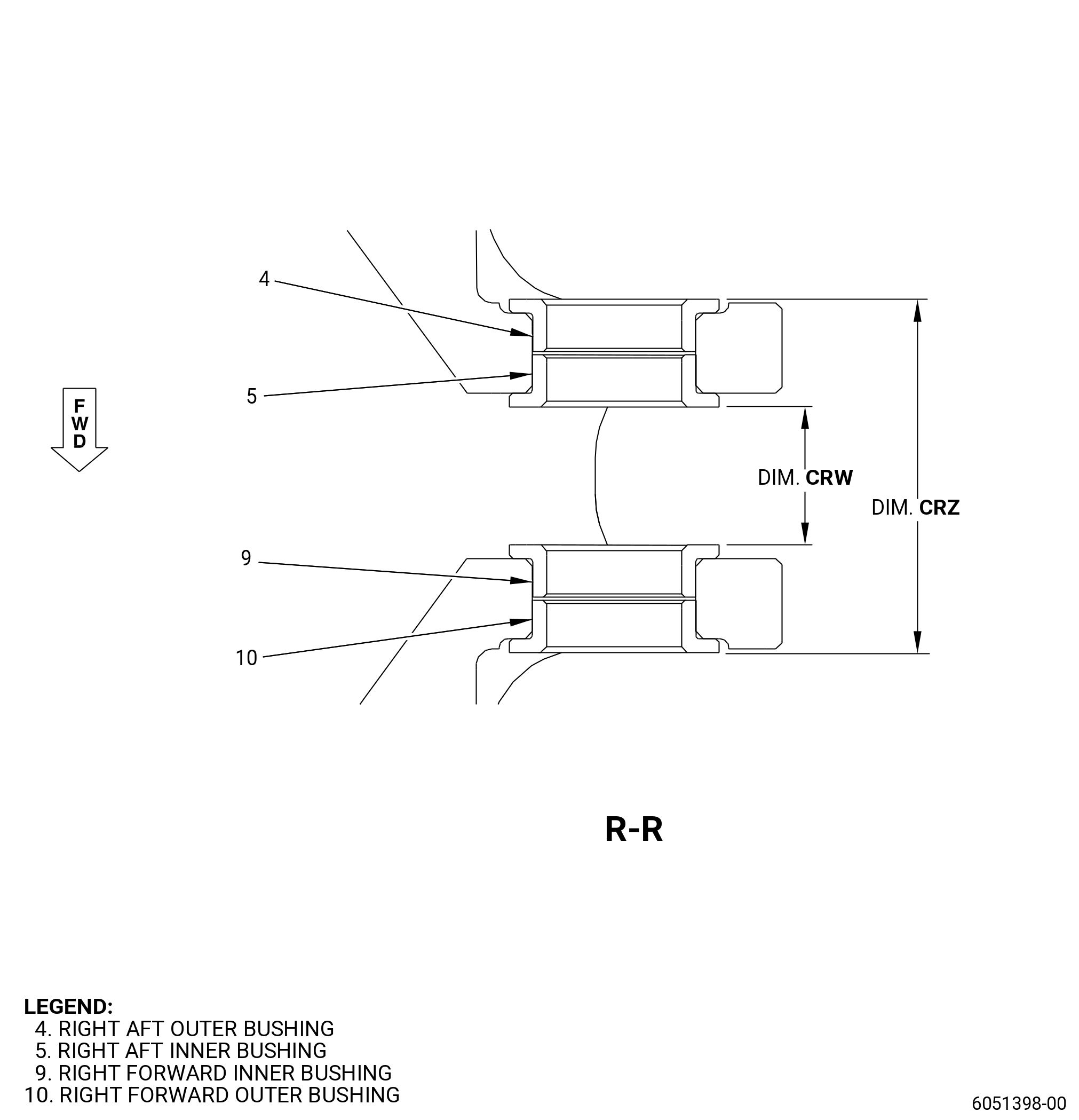
| (14) | Alternative Procedure Available. Dimension CRZ: |
| NOTE: |
|
| Maximum serviceable limit: |
|
| Repair method: |
|
| • |
|
| • |
|
| NOTE: |
|
| Subtask 72-21-06-220-029 |
| (14).A. | Alternative Procedure. Dimension CRZ: |
| NOTE: |
|
| Maximum serviceable limit: |
|
| Repair method: |
|
| Subtask 72-21-06-220-030 |
| (15) | Alternative Procedure Available. Dimension CRW: |
| NOTE: |
|
| Minimum serviceable limit: |
|
| Repair method: |
|
| • |
|
| • |
|
| NOTE: |
|
| Subtask 72-21-06-220-031 |
| (15).A. | Alternative Procedure. Dimension CRW: |
| NOTE: |
|
| Minimum serviceable limit: |
|
| Repair method: |
|
| Subtask 72-21-06-220-032 |
| B. | Do an inspection of the bushing. Refer to Figure 802. |
| (1) | Wear or fretting: |
| Maximum serviceable limit: |
|
| Repair method: |
|