| GENX-1B CLEANING,INSPECTION,AND REPAIR MANUAL | Dated: 03/31/2012 | |
| CIR 72-22-40 , REPAIR 001 | ||
| STAGE 1 FAN DISK - REPAIR - BLEND REPAIR OF THE FAN DISK POST FORWARD FACE AND CHAMFER (AREA F) | ||
| GENX-1B CLEANING,INSPECTION,AND REPAIR MANUAL | Dated: 03/31/2012 | |
| CIR 72-22-40 , REPAIR 001 | ||
| STAGE 1 FAN DISK - REPAIR - BLEND REPAIR OF THE FAN DISK POST FORWARD FACE AND CHAMFER (AREA F) | ||
| * * * FOR ALL |
| TASK 72-22-40-300-801 |
| 1 . | Repair for the Stage 1 Fan Disk. |
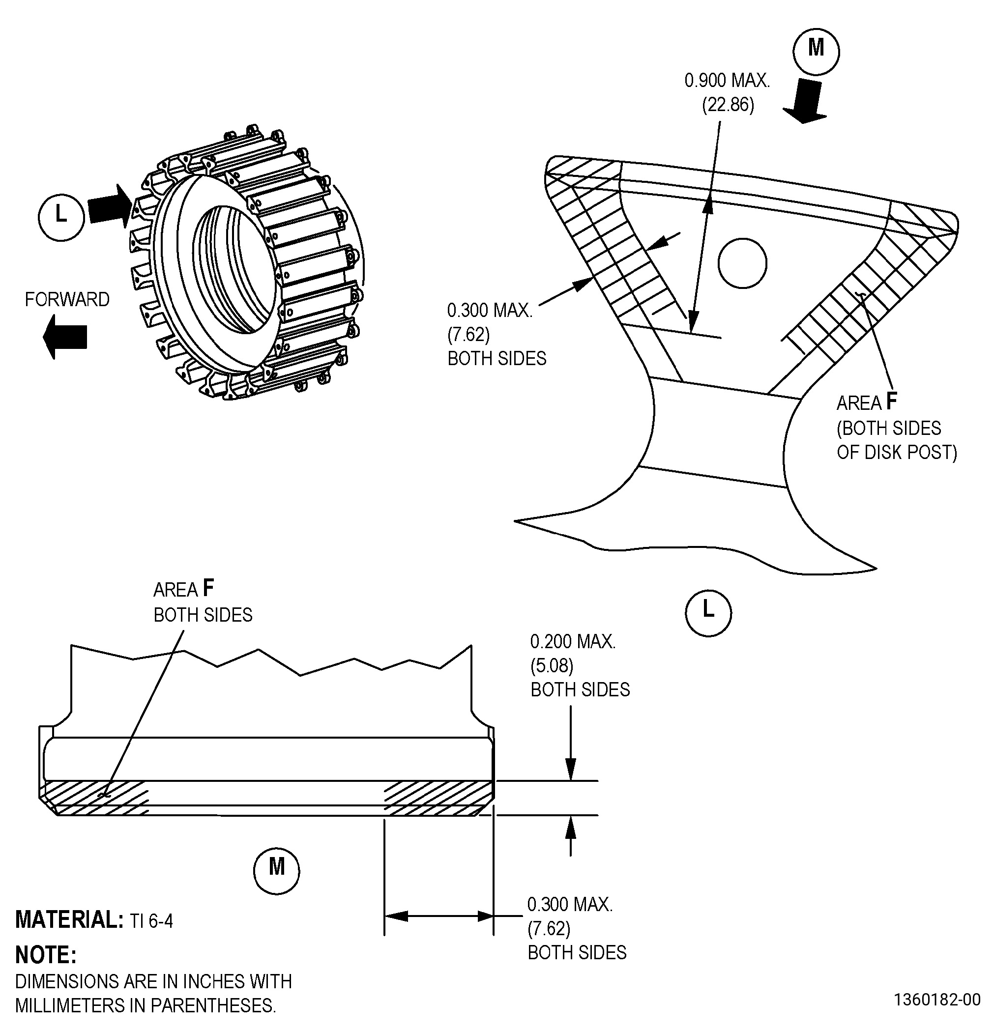
| A. | This procedure gives instructions to repair the stage 1 fan disk by blending the disk post forward face and chamfer (area F) to remove the damaged areas. Refer to Figure 901. |
| B. | The following maximum repairable limits apply to this repair: |
| NOTE: |
|
| NOTE: |
|
| (4) | Visual Inspection. |
| (a) | Do an inspection of all areas of the fan disk for: |
| 8 | Nicks, dents, and scratches (on the spinner aft support ring flange mating face chamfer (area F)): |
| Maximum repairable limit: |
|
| C. | The subsequent table gives a list of the part numbers that are applicable to this repair. All part numbers are applicable to all paragraphs unless specified differently. |
|
|||||||||||||||||||||||
| D. | Proprietary/Complex Process Statement. |
| (1) | None. |
| 2 . | Tools, Equipment, and Materials. |
| NOTE: |
|
| A. | Tools and Equipment. |
| (1) | Special Tools. None. |
| (2) | Standard Tools and Equipment. None. |
| (3) | Locally Manufactured Tools. None. |
| B. | Consumable Materials. |
| C. | Referenced Procedures. |
|
| D. | Expendable Parts. None. |
| E. | SPD Information. None. |
| F. | Special Solutions. None. |
| G. | Test Specimens. None. |
| 3 . | Dimensional Information. |
| Subtask 72-22-40-220-033 |
| A. | Refer to Figure 901 and Figure 902 for specified dimensions and locations. |
| NOTE: |
|
| 4 . | Setup Information. |
| None. |
| 5 . | Procedure. |
| Subtask 72-22-40-100-001 |
| A. | Clean the fan disk. Refer to TASK 72-22-40-100-801 (72-22-40, CLEANING 001). |
| Subtask 72-22-40-350-001 |
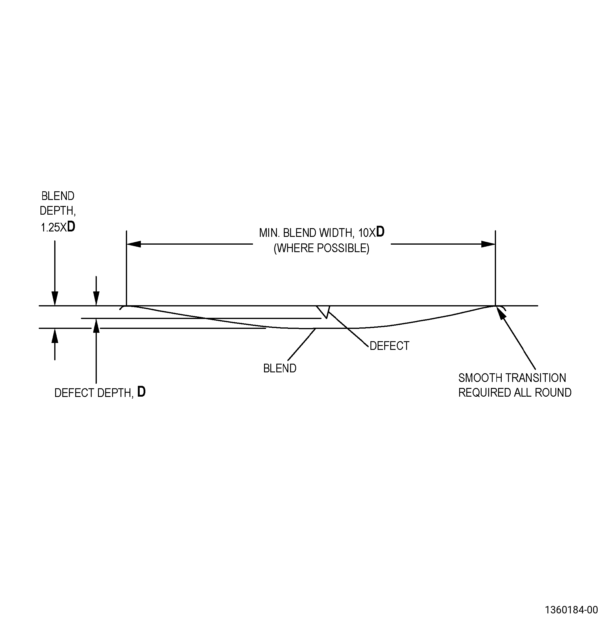
| B. | Blend the fan disk area F to remove the worn/damaged areas. Refer to TASK 70-42-00-350-002 (BLENDING AND REMOVAL OF HIGH METAL PROCEDURES), Figure 901, Figure 902, and as follows: |
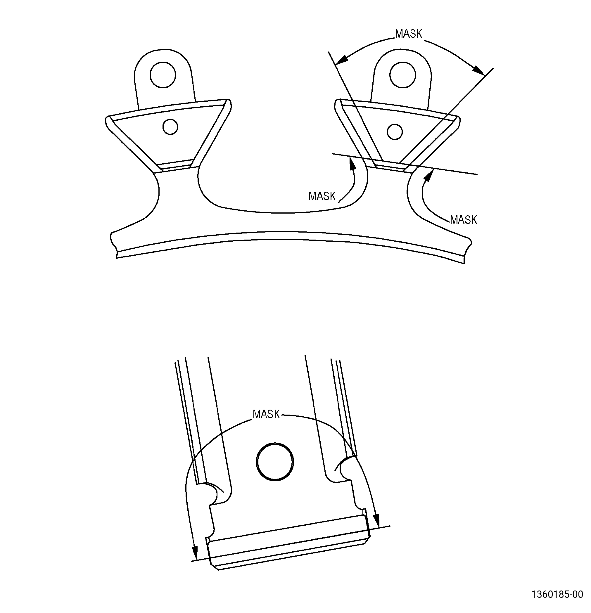
| (1) | Apply C10-021 masking tape to adjacent surfaces that are not within area F, where blending is not permitted. Refer to Figure 903. |
| CAUTION: |
|
| (2) | Blend the damaged area smooth to adjacent contour and remove as little parent material as possible to meet the required dimensions. |
| (3) | Blend all sharp edges/corners smooth to a minimum radius of 0.030 inch (0.77 mm). |
| Subtask 72-22-40-110-007 |
| C. | Etch the fan disk blended areas. Refer to TASK 70-24-00-110-033 (ETCHING PROCEDURES FOR FLUORESCENT-PENETRANT INSPECTION) , TASK 70-24-01-110-034 (SWAB ETCHING PROCEDURE) , and as follows: |
| (1) | Use Class B etchant. |
| Subtask 72-22-40-200-001 |
| D. | Do an inspection of the fan disk etched areas. Refer to TASK 70-32-00-200-002 (INDIRECT INSPECTION METHODS), TASK 70-32-03-230-002 (SPOT-FLUORESCENT-PENETRANT INSPECTION), and as follows: |
| (1) | Use Class G penetrant. |
| (2) | Refer to TASK 72-22-40-200-801 (72-22-40, INSPECTION 001) for the acceptance limits. |
| Subtask 72-22-40-100-002 |
| E. | If necessary, clean the fan disk to remove remaining etchant/penetrant. Refer to TASK 70-21-00-110-051 (CHEMICAL CLEANING) and TASK 70-21-03-160-001 (CLEANING METHOD 3 - STEAM CLEANING). |
| Subtask 72-22-40-380-001 |
| F. | Peen the fan disk repaired areas. Refer to TASK 70-47-01-380-016 (SHOTPEENING) and as follows: |
| (1) | Apply C10-021 masking tape to adjacent surfaces that will not be peened. |
| (2) | Use C04-271 S110 cast steel shot. |
| (3) | Use an intensity of 0.004A-0.008A. |
| (4) | Use C10-110 almen test strips and an almen strip holder to verify the intensity at the repaired area. |
| (5) | Overspray is permitted. |
| Subtask 72-22-40-200-002 |
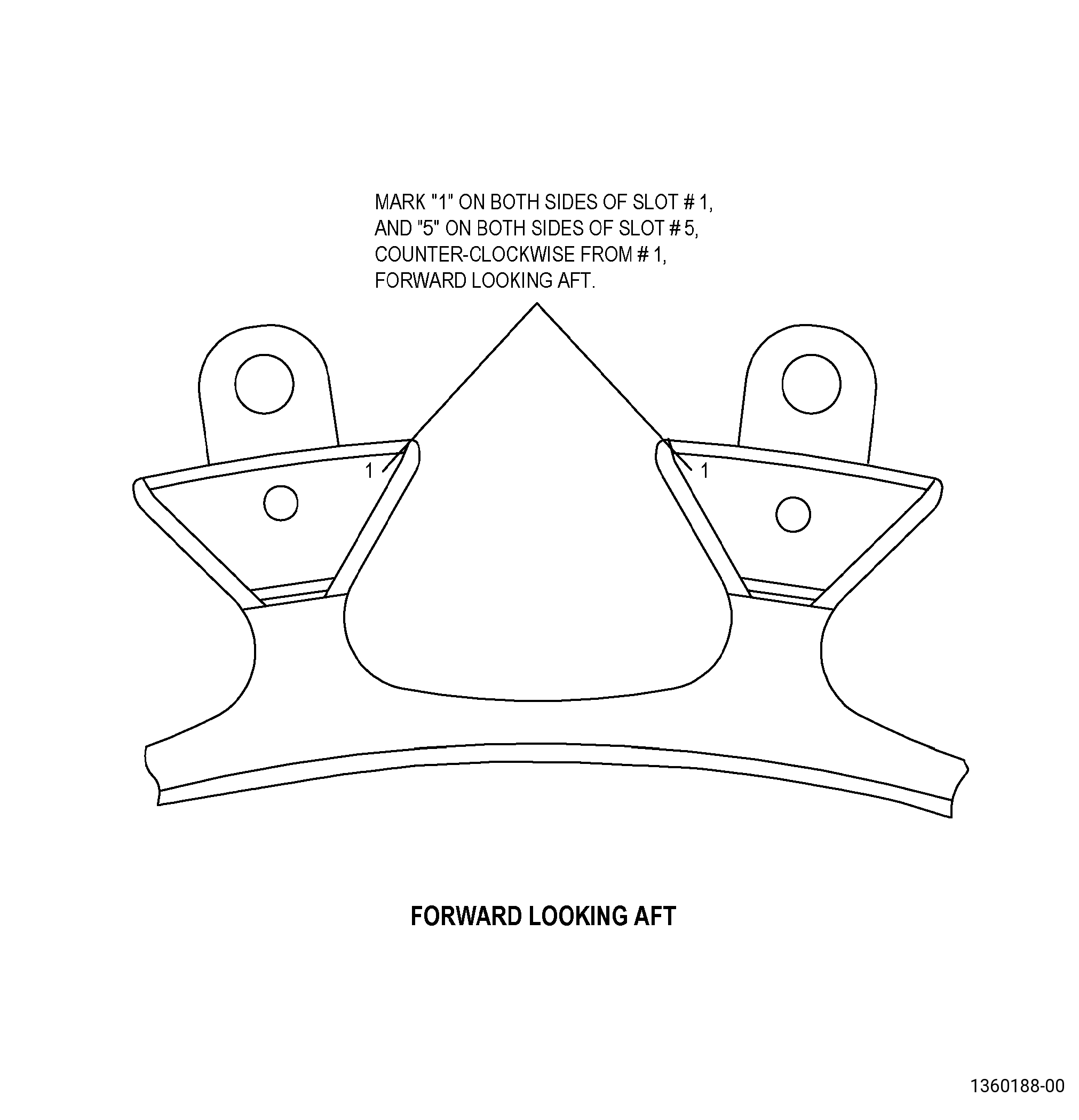
| G. | Do an inspection of the fan disk dovetail slots. Refer to Figure 904 and as follows: |
| Subtask 72-22-40-350-002 |
| CAUTION: |
|
| (1) | Alternative Procedure Available. If the marks “1” or “5” have been damaged during this repair procedure, put a mark on the dovetail slot. Refer to TASK 70-16-00-350-001 (MARKING PRACTICES), TASK 70-16-05-350-020 (METAL STAMP MARKING), and as follows: |
| (a) | If it is not possible to put the mark back at the initial position, put a line through the initial mark and put the new mark adjacent to it. |
| (b) | Make sure that the mark is a minimum of 0.05 inch (1.3 mm) from all edges and radii, and must be of the same height as the initial mark. |
| Subtask 72-22-40-350-003 |
| (1).A. | Alternative Procedure. If the marks “1” or “5” have been damaged during this repair procedure, put a mark on the dovetail slot. Refer to TASK 70-16-00-350-001 (MARKING PRACTICES), TASK 70-16-08-350-001 (DOT PEEN MARKING FOR OPTICAL CHARACTER RECOGNITION), and as follows: |
| (a) | If it is not possible to put the mark back at the initial position, put a line through the initial mark and put the new mark adjacent to it. |
| (b) | Make sure that the mark is a minimum of 0.05 inch (1.3 mm) from all edges and radii, and must be of the same height as the initial mark. |
| Subtask 72-22-40-350-004 |
| H. | Remove all the masking tape. |