| GENX-1B CLEANING,INSPECTION,AND REPAIR MANUAL | Dated: 10/31/2016 | |
| CIR 72-22-41 , REPAIR 002 | ||
| BOOSTER SPOOL - REPAIR - GENERAL BLEND REPAIR OF THE BOOSTER SPOOL STAGE 2-5 | ||
| GENX-1B CLEANING,INSPECTION,AND REPAIR MANUAL | Dated: 10/31/2016 | |
| CIR 72-22-41 , REPAIR 002 | ||
| BOOSTER SPOOL - REPAIR - GENERAL BLEND REPAIR OF THE BOOSTER SPOOL STAGE 2-5 | ||
| * * * FOR ALL |
| TASK 72-22-41-300-802 |
| 1 . | General Blend Repair of the Booster Spool Stage 2-5. |
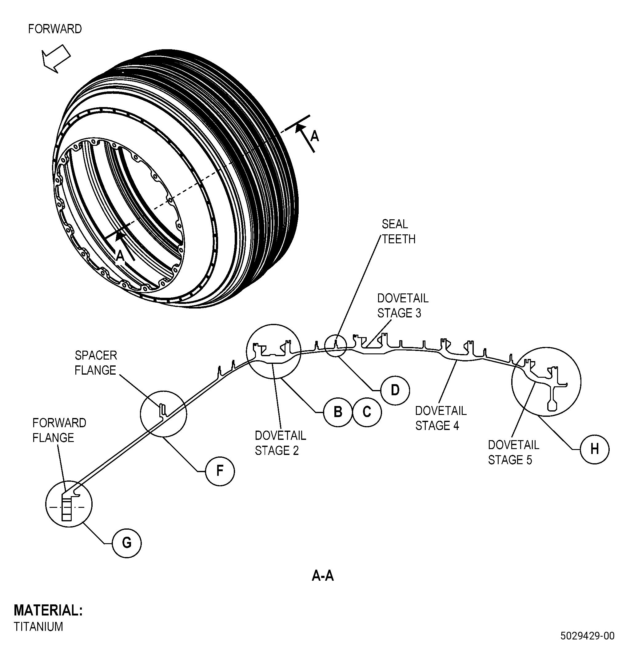
| A. | This procedure gives instructions to repair the booster spool by blending the stage 2-5. Refer to Figure 901. |
| B. | The following maximum repairable limits apply to this repair: |
| NOTE: |
|
| (4) | Visual Inspection. |
| (a) | Do an inspection of all areas (does not include boltholes, dovetails slot, dovetail areas, dovetail load and lock slots, flanges, and seal teeth) for: |
| 2 | Nicks, dents, and scratches: |
| Maximum repairable limit: |
|
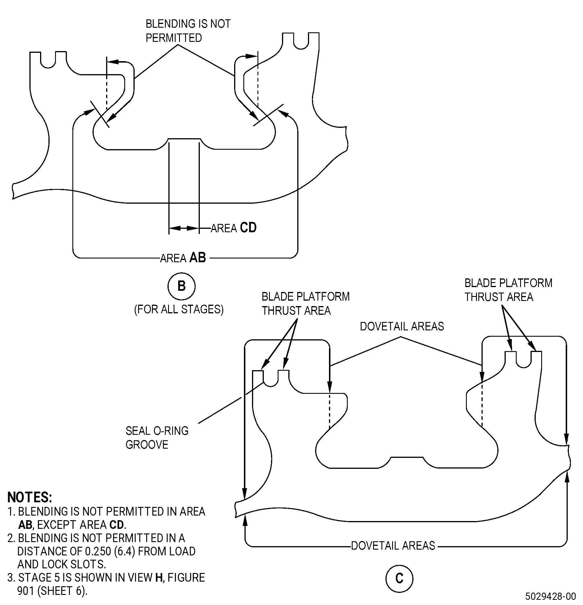
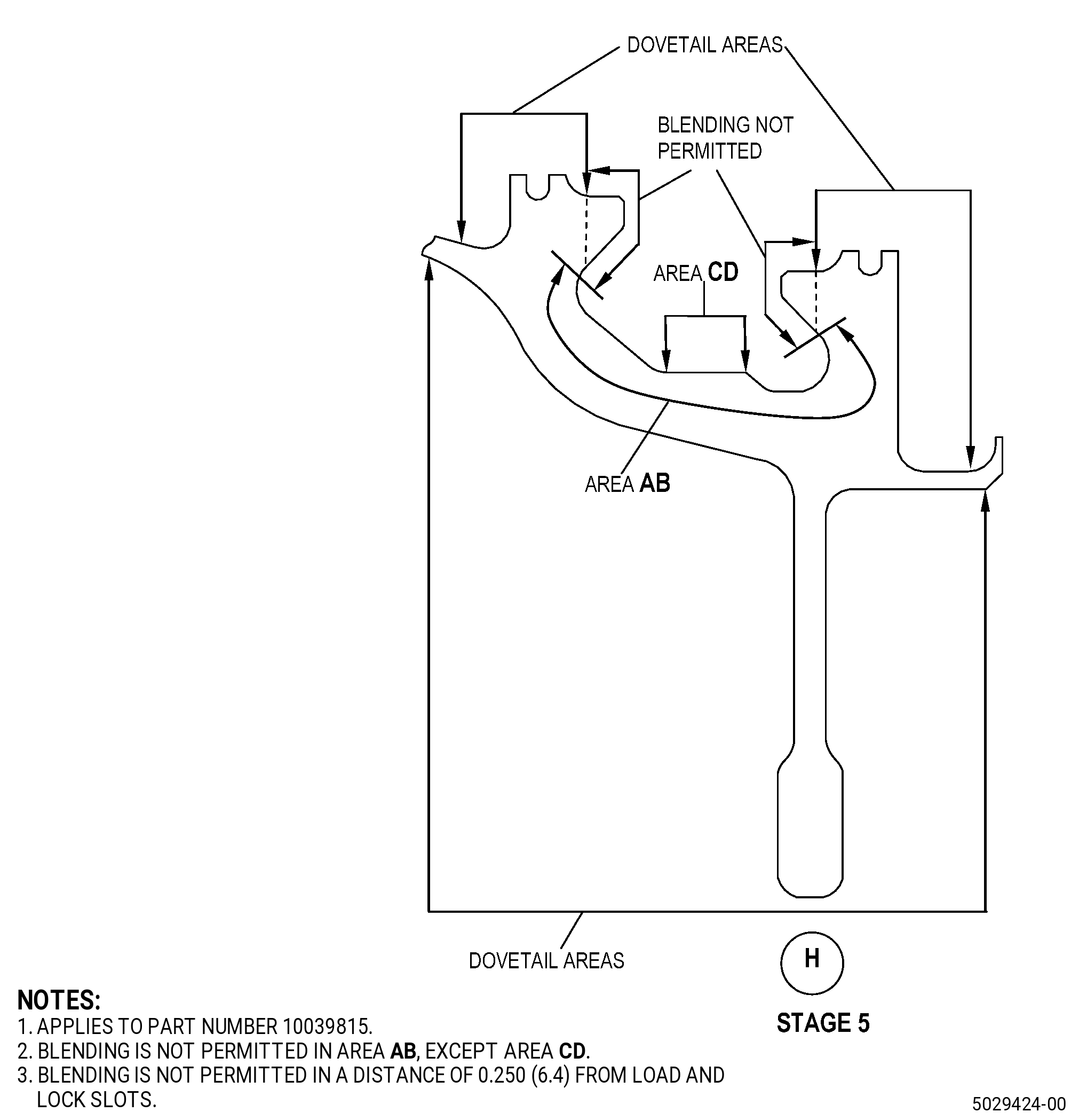
| (b) | Do an inspection of the dovetail slots for: |
| 3 | Nicks, dents, and scratches on bottom of dovetails (area AB): |
| NOTE: |
|
| Maximum repairable limit: |
|
| (c) | Do an inspection of the dovetails areas for: |
| 1 | Wear, nicks, dents, and scratches: |
| Maximum repairable limit: |
|
| Limitations: |
| • |
|
| • |
|
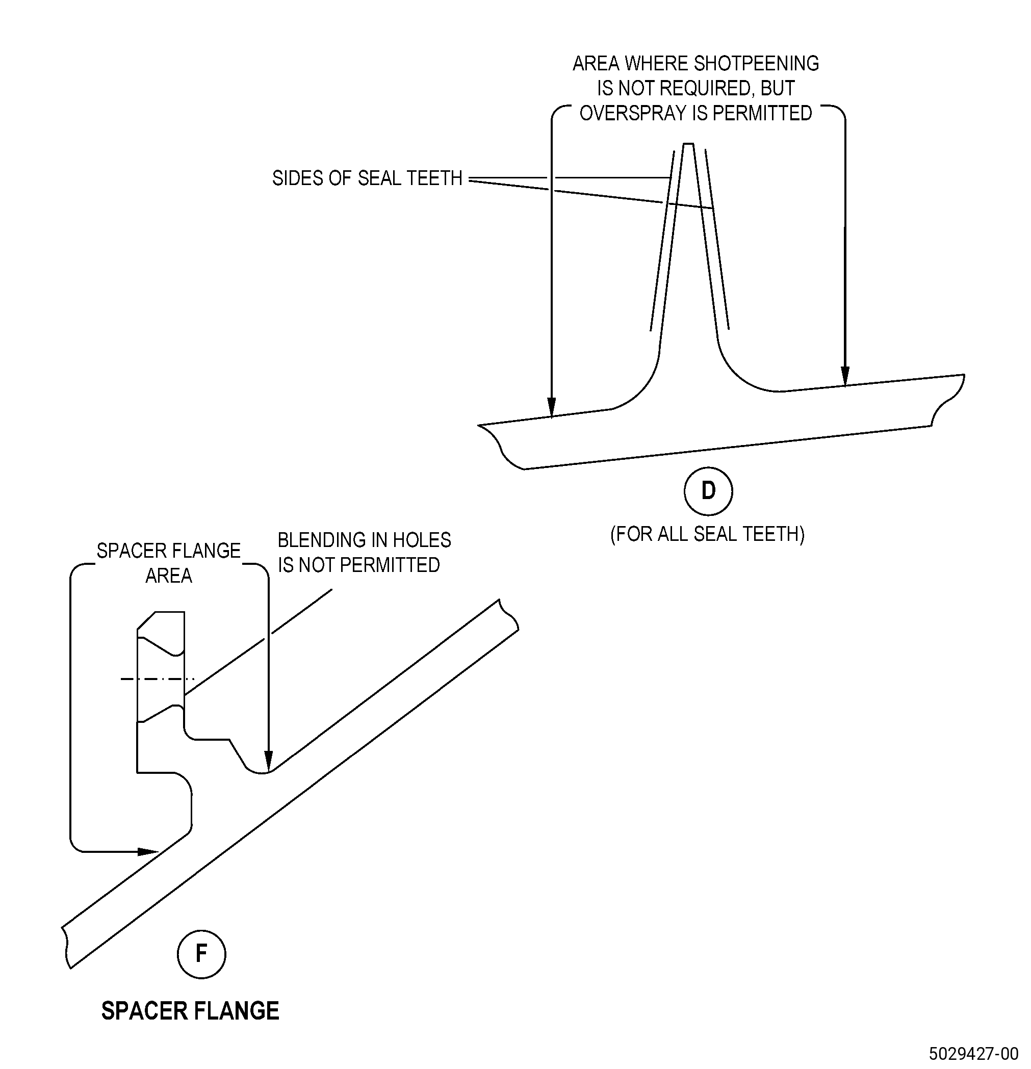
| (d) | Do an inspection of seal teeth for: |
| 2 | Rub marks, nicks, dents, and scratches at the seal teeth diameter (tips): |
| Maximum repairable limit: |
|
| 7 | Rub marks, nicks, dents, and scratches at sides of seal teeth: |
| Maximum repairable limit: |
|
| (f) | Do an inspection of the spacer flange for: |
| 3 | Nicks, dents, and scratches: |
| Maximum repairable limit: |
|
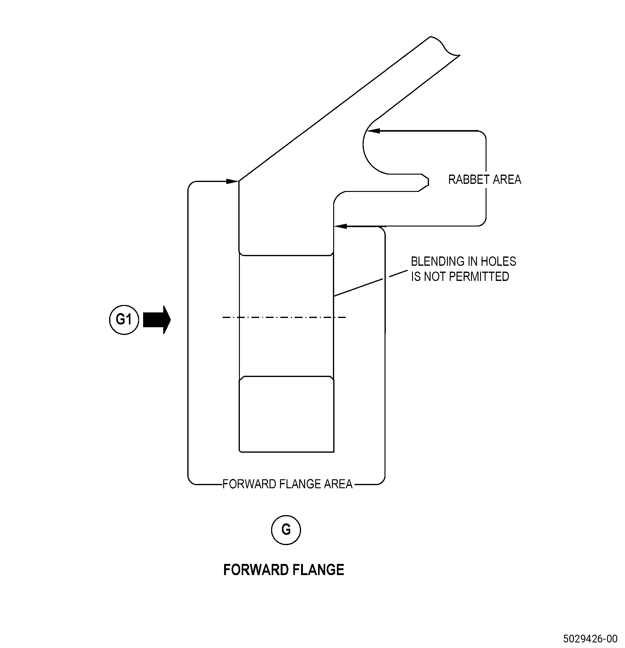
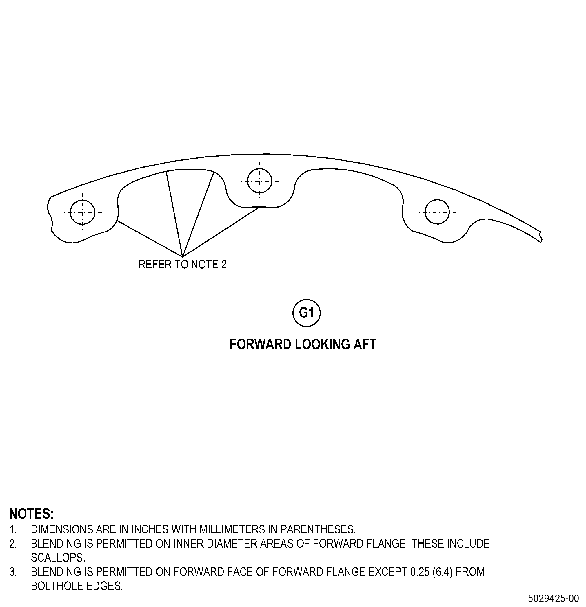
| (g) | Do an inspection of the forward flange for: |
| 2 | Nicks, dents, and scratches: |
| Maximum repairable limit: |
|
| 3 | Nicks, dents, and scratches at rabbet area: |
| Maximum repairable limit: |
|
| C. | The subsequent table gives a list of the part numbers that are applicable to this repair. All part numbers are applicable to all paragraphs unless specified differently. |
|
|||||||||||||||||||||||
| D. | Proprietary/Complex Process Statement. |
| (1) | None. |
| 2 . | Tools, Equipment, and Materials. |
| NOTE: |
|
| A. | Tools and Equipment. |
| (1) | Special Tools. None. |
| (2) | Standard Tools and Equipment. None. |
| (3) | Locally Manufactured Tools. None. |
| B. | Consumable Materials. |
|
| C. | Referenced Procedures. |
| D. | Expendable Parts. None. |
| E. | SPD Information. |
| (1) | Locally Manufactured SPD. None. |
| F. | Special Solutions. None. |
| G. | Test Specimens. None. |
| 3 . | Dimensional Information. |
| Subtask 72-22-41-220-065 |
| A. | Refer to Figure 901 for specified dimensions and locations. |
| NOTE: |
|
| NOTE: |
|
| 4 . | Setup Information. |
| None. |
| 5 . | Procedure. |
| Subtask 72-22-41-350-008 |
| A. | If necessary, remove the shank nut from the booster spool. Refer to TASK 72-22-41-300-801 (72-22-41, REPAIR 001). |
| Subtask 72-22-41-350-009 |
| CAUTION: |
|
| B. | Blend the booster spool. Refer to TASK 70-42-00-350-002 (BLENDING AND REMOVAL OF HIGH METAL PROCEDURES), Figure 901, and as follows: |
| (1) | The damage must be completely removed. The blend depth must be a minimum of 1.25 times the depth of the damage. |
| (2) | Remove the minimum quantity of material during the blending process. Do not blend more than the maximum depth or less than the minimum blend radius. |
| (3) | Break all edges to 0.010-0.020 inch (0.25-0.50 mm). |
| Subtask 72-22-41-160-002 |
| C. | Clean the repair areas of the booster spool. Refer to TASK 70-21-00-110-051 (CHEMICAL CLEANING) and TASK 70-21-03-160-001 (CLEANING METHOD NO. 3 - STEAM CLEANING). |
| Subtask 72-22-41-110-007 |
| D. | Etch the repair areas of the booster spool. Refer to TASK 70-24-00-110-033 (ETCHING PROCEDURES FOR FLUORESCENT-PENETRANT INSPECTION), TASK 70-24-01-110-034 (SWAB ETCHING PROCEDURE), and as follows: |
| (1) | Use Class B etchant. |
| Subtask 72-22-41-230-004 |
| E. | Alternative Procedure Available. Do an inspection of the repair areas of the booster spool. Refer to TASK 70-32-00-200-002 (INDIRECT INSPECTION METHODS), TASK 70-32-02-230-001 (FLUORESCENT PENETRANT INSPECTION), and as follows: |
| (1) | Use Class G penetrant. |
| (2) | Indications more than 0.015 inch (0.38 mm) are not permitted. |
| (3) | Indications that go across corners or in fillets are not permitted. |
| (4) | Linear indications are not permitted. |
| NOTE: |
|
| Subtask 72-22-41-230-005 |
| E.A. | Alternative Procedure. Do an inspection of the repair areas of the booster spool. Refer to TASK 70-32-00-200-002 (INDIRECT INSPECTION METHODS), TASK 70-32-03-230-002 (SPOT-FLUORESCENT-PENETRANT INSPECTION), and as follows: |
| (1) | Use Class G penetrant. |
| (2) | Indications more than 0.015 inch (0.38 mm) are not permitted. |
| (3) | Indications that go across corners or in fillets are not permitted. |
| (4) | Linear indications are not permitted. |
| NOTE: |
|
| Subtask 72-22-41-350-010 |
| WARNING: |
|
| F. | Polish the repair area of the booster spool to remove the effects of the swab etching procedure as follows: |
| (1) | Use C10-010 abrasive cloth. |
| Subtask 72-22-41-380-001 |
| WARNING: |
|
| G. | Peen the repair areas of the booster spool. Refer to TASK 70-47-01-380-016 (SHOTPEENING) and as follows: |
| (1) | Use C04-166 CCW14 shot. |
| (2) | Use C10-205 type N Almen strips. |
| (3) | Peen the booster spool to an intensity of 0.006-0.012N. |
| (4) | Intensity verification is necessary at all repaired locations. |
| (a) | Make sure that you do the intensity verification with a simulative fixture. |
| (5) | Coverage must be a minimum of 100 percent, except on seal teeth. Overspray on seal teeth is permitted, but not required. |
| (6) | Perform visual inspection of all edges to assure that no burrs or rollover of edges has occurred after peening. |
| Subtask 72-22-41-160-003 |
| H. | Clean the repair areas of the booster spool. Refer to TASK 70-21-00-110-051 (CHEMICAL CLEANING) and TASK 70-21-03-160-001 (CLEANING METHOD NO. 3 - STEAM CLEANING). |
| Subtask 72-22-41-350-011 |
| I. | If necessary, replace the shank nut. Refer to TASK 72-22-41-300-801 (72-22-41, REPAIR 001). |
| Subtask 72-22-41-220-066 |
| J. | Do a final visual inspection of the booster spool blended areas. Refer to TASK 72-22-41-200-805 (72-22-41, INSPECTION 001). |