| GENX-1B CLEANING,INSPECTION,AND REPAIR MANUAL | Dated: 10/31/2019 | |
| CIR 72-22-43 , REPAIR 001 | ||
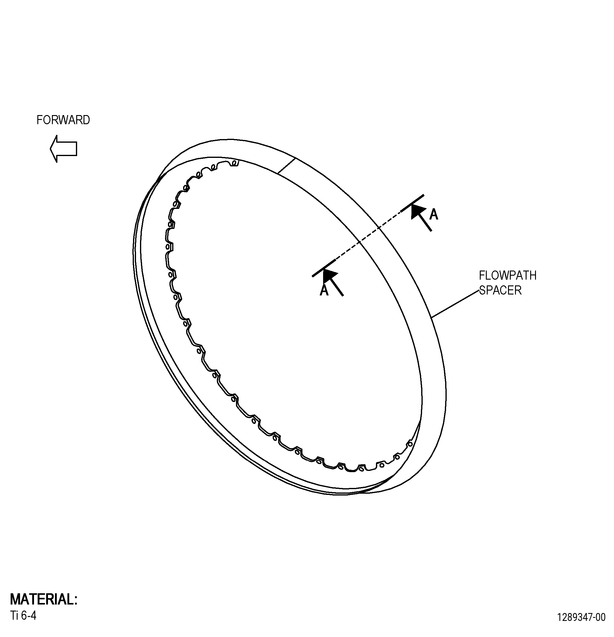
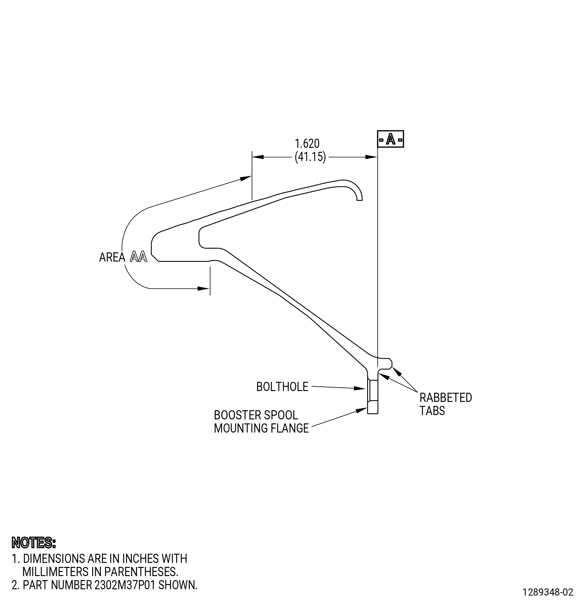
| FAN MODULE ASSEMBLY - FLOWPATH SPACER - REPAIR - BLEND REPAIR | ||
| GENX-1B CLEANING,INSPECTION,AND REPAIR MANUAL | Dated: 10/31/2019 | |
| CIR 72-22-43 , REPAIR 001 | ||
| FAN MODULE ASSEMBLY - FLOWPATH SPACER - REPAIR - BLEND REPAIR | ||
| * * * FOR ALL |
| TASK 72-22-43-300-801 |
| 1 . | Repair for the Flowpath Spacer. |
| A. | This procedure gives instructions to repair the flowpath spacer (spacer) by blending. Refer to Figure 901. |
| B. | The following Maximum Repairable limits apply to this repair: |
| NOTE: |
|
| NOTE: |
|
| (4) | Visual Inspection. |
| (a) | Do an inspection of all areas of the flowpath spacer (area AA and the mounting flange not included) for: |
| 2 | Nicks, dents, scratches, and pits: |
| Maximum repairable limit: |
|
| (b) | Do an inspection of area AA on the flowpath spacer for: |
| 1 | Nicks, dents, scratches, and pits: |
| Maximum repairable limit: |
|
| 2 | Fretting and wear: |
| Maximum repairable limit: |
|
| (c) | Do an inspection of the forward and aft surfaces of the mounting flange for: |
| 1 | Nicks, dents, and scratches: |
| Maximum repairable limit: |
|
| 3 | Fretting: |
| Maximum repairable limit: |
|
| (d) | Do an inspection of the boltholes for: |
| 1 | Thread marks and scratches: |
| Maximum repairable limit: |
|
| C. | The subsequent table gives a list of the part numbers that are applicable to this repair. All part numbers are applicable to all paragraphs unless specified differently. |
|
|||||||||||||||||||||||
| D. | Proprietary/Complex Process Statement. |
| (1) | None. |
| 2 . | Tools, Equipment, and Materials. |
| NOTE: |
|
| A. | Tools and Equipment. |
| (1) | Special Tools. None. |
| (2) | Standard Tools and Equipment. none |
| (3) | Locally Manufactured Tools. None. |
| B. | Consumable Materials. None. |
| C. | Referenced Procedures. |
| D. | Expendable Parts. None. |
| E. | SPD Information. None |
| F. | Special Solutions. None. |
| G. | Test Specimens. None. |
| 3 . | Dimensional Information. |
| Subtask 72-22-43-220-019 |
| A. | Refer to Figure 901 for specified dimensions and locations. |
| NOTE: |
|
| 4 . | Setup Information. |
| None. |
| 5 . | Procedure. |
| Subtask 72-22-43-110-007 |
| A. | Clean the spacer. Refer to TASK 70-21-00-110-051 (CHEMICAL CLEANING) and TASK 70-21-03-160-001 (CLEANING METHOD NO. 3 - STEAM CLEANING). |
| Subtask 72-22-43-160-004 |
| B. | Do a visual inspection of the spacer for surface defects or corrosion. Refer to TASK 72-22-43-200-801 (72-22-43, INSPECTION 001). |
| Subtask 72-22-43-350-001 |
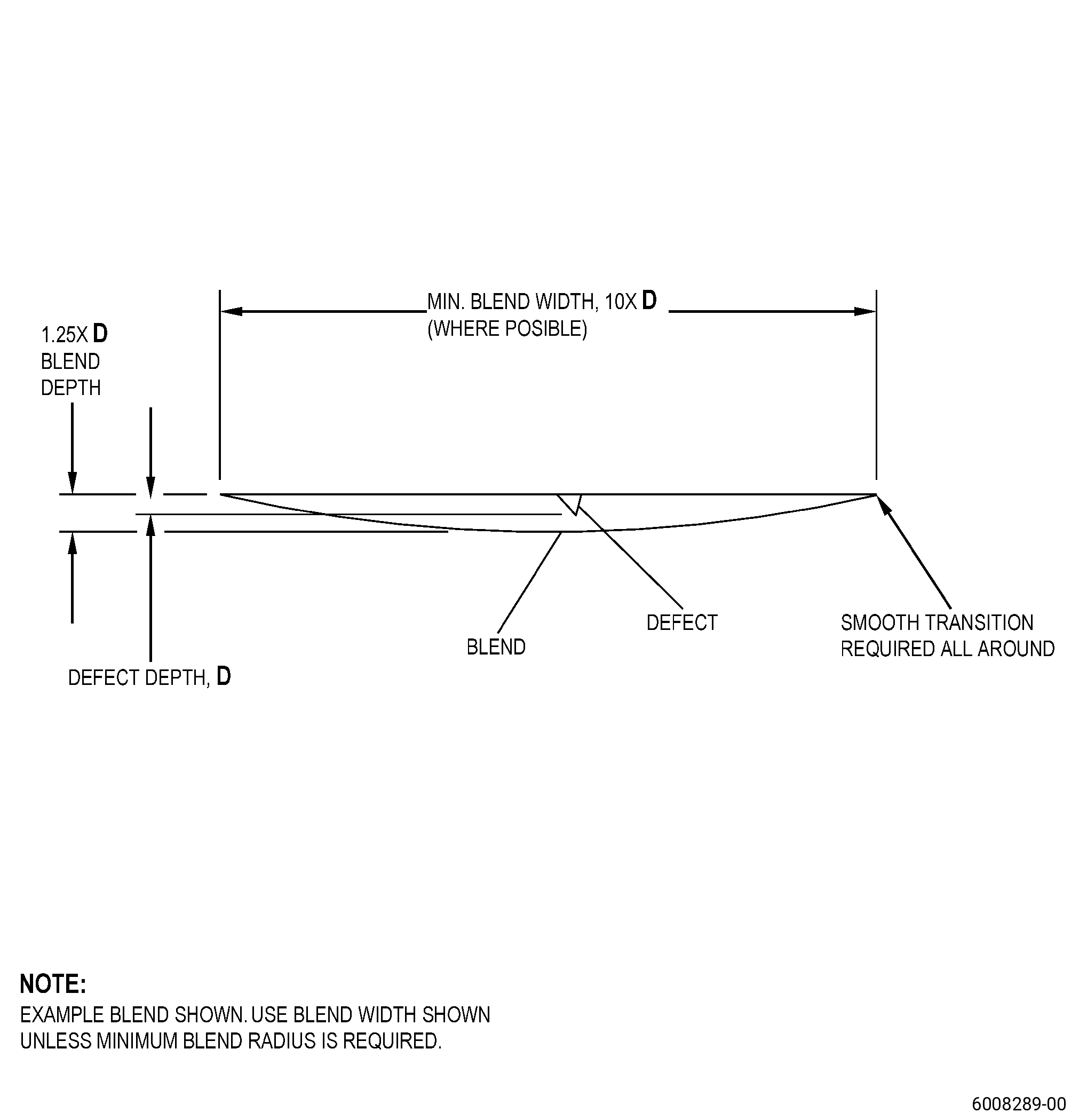
| C. | Blend the spacer. Refer to TASK 70-42-00-350-002 (BLENDING AND REMOVAL OF HIGH METAL PROCEDURES), Figure 902, Figure 904, and as follows: |
| (1) | Remove the minimum quantity of material to get the maximum repairable limit. |
| (2) | Break all sharp edges to 0.015 to 0.030 inch (0.39 to 0.76 mm). |
| (3) | Deleted. |
| (4) | Deleted. |
| (a) | Deleted. |
| 1 | Deleted. |
| Subtask 72-22-43-220-020 |
| 2 | Deleted. |
| 3 | Deleted. |
| 4 | Deleted. |
| Subtask 72-22-43-350-002 |
| (c) | Deleted. |
| (5) | Deleted. |
| Subtask 72-22-43-110-008 |
| D. | Etch the spacer repair area. Refer to TASK 70-24-00-110-033 (ETCHING PROCEDURES FOR FLUORESCENT-PENETRANT INSPECTION), TASK 70-24-01-110-034 (SWAB ETCHING PROCEDURE), and as follows: |
| (1) | Use Class B etchant. |
| Subtask 72-22-43-230-002 |
| E. | Do an inspection of the spacer repair area. Refer to TASK 70-32-00-200-002 (INDIRECT INSPECTION METHODS), TASK 70-32-03-230-002 (SPOT-FLUORESCENT-PENETRANT INSPECTION), and as follows: |
| (1) | Use Class G penetrant. |
| (2) | Indications less than 0.015 inch (0.38 mm) are permitted. |
| Subtask 72-22-43-110-009 |
| F. | Clean the spacer. Refer to TASK 70-21-00-110-051 (CHEMICAL CLEANING) and TASK 70-21-03-160-001 (CLEANING METHOD NO. 3 - STEAM CLEANING). |
| Subtask 72-22-43-380-001 |
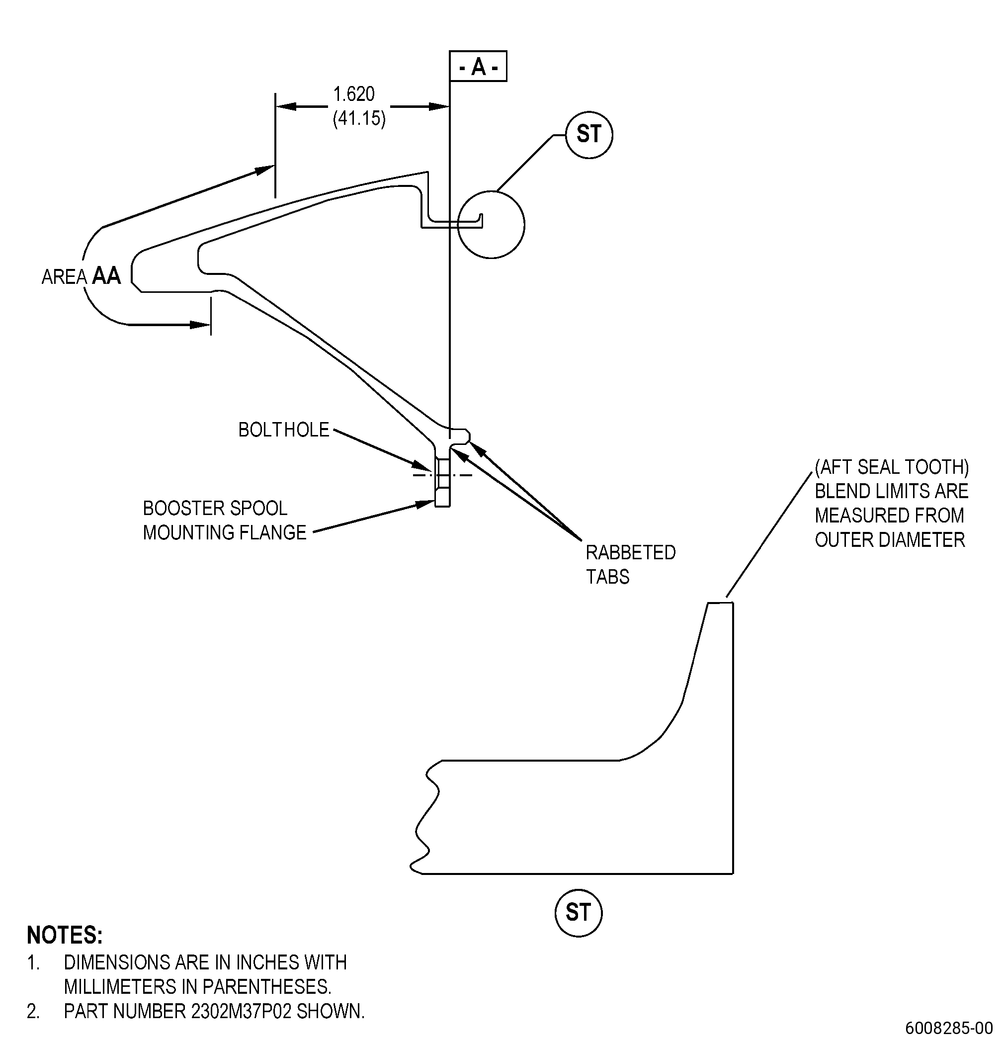
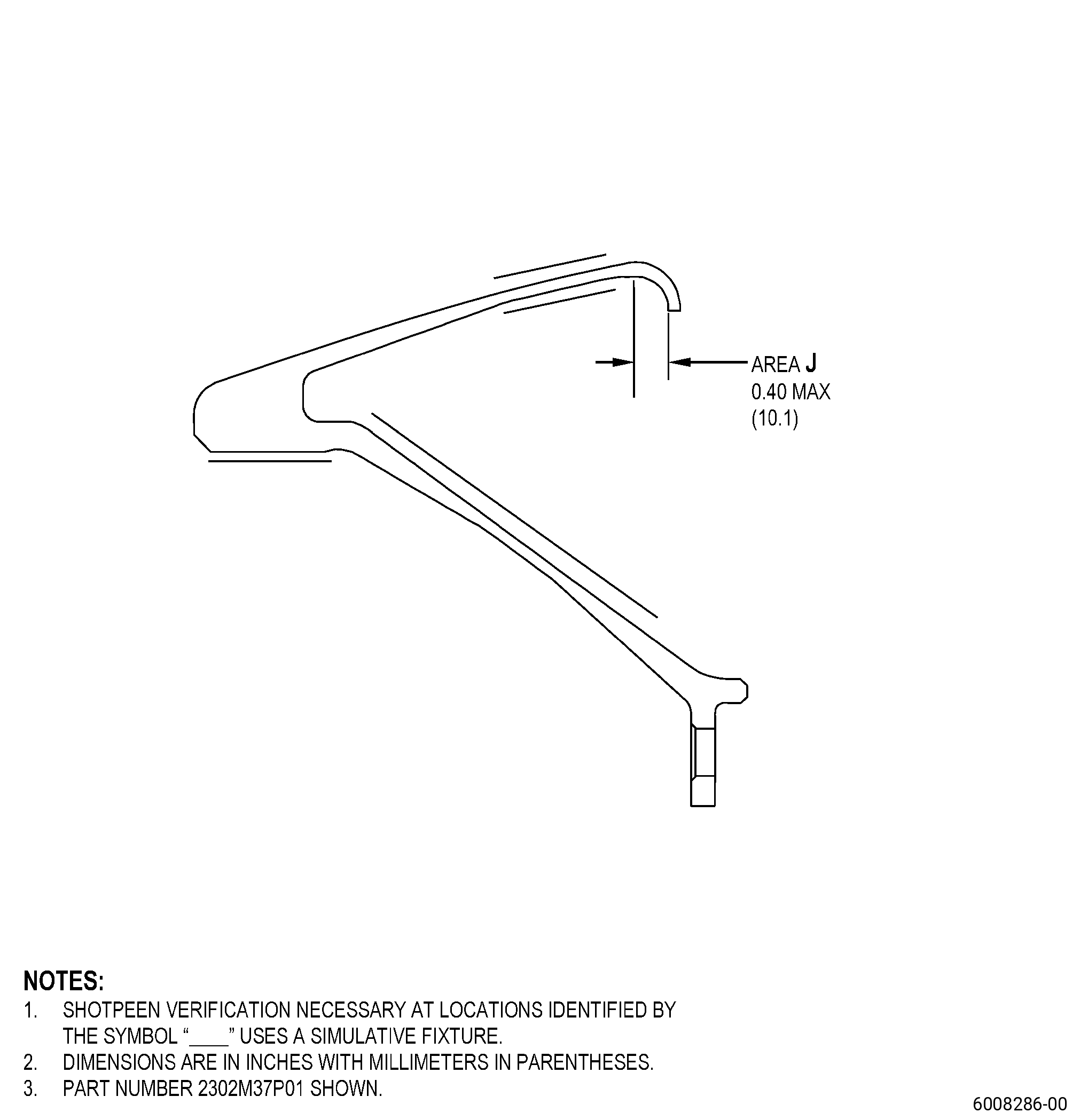
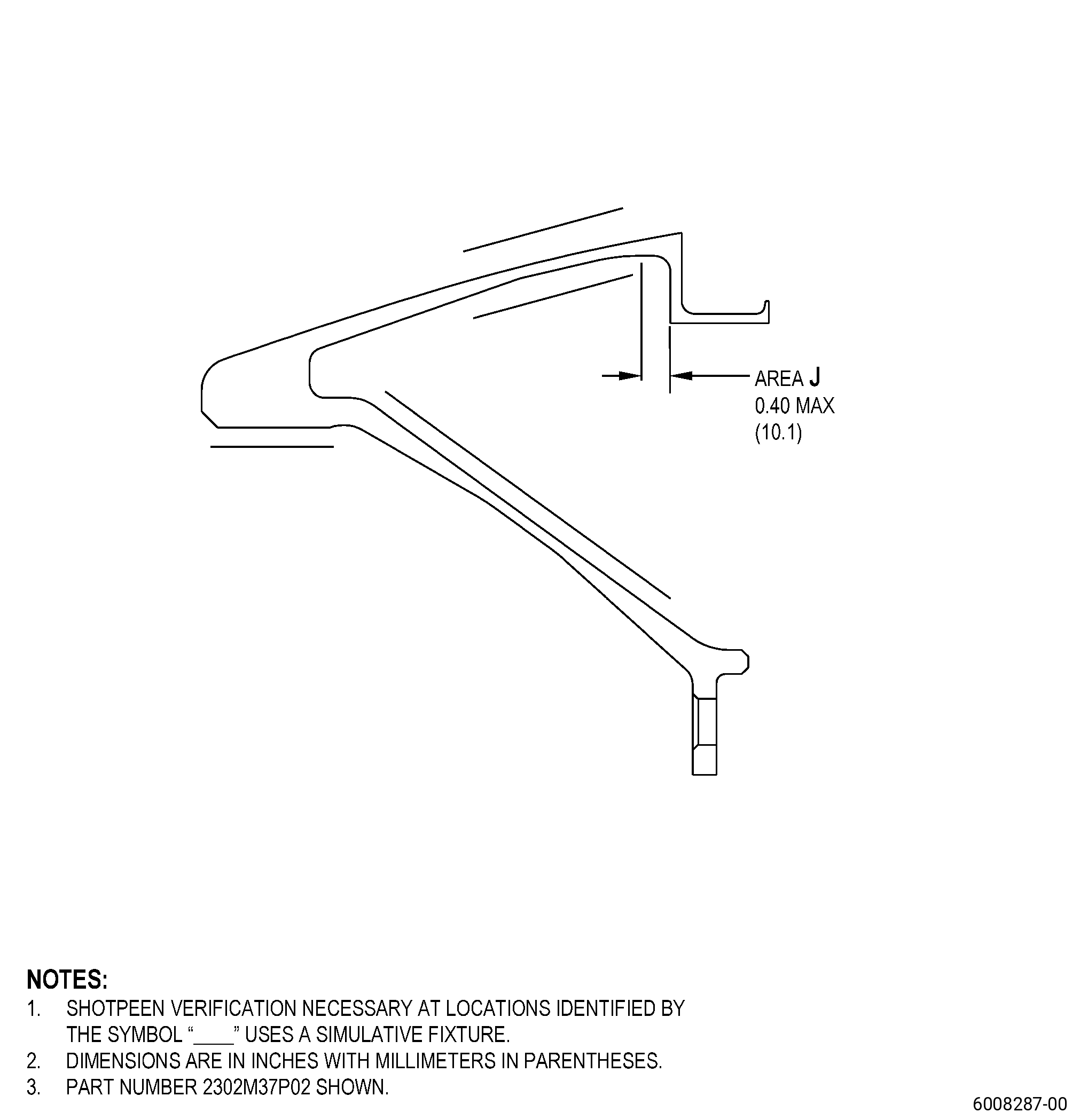
| G. | Peen the spacer repair area. Refer to TASK 70-47-01-380-016 (SHOTPEENING), Figure 903, and as follows: |
| NOTE: |
|
| (1) | Use 110 steel shot. |
| (2) | Peen at an intensity of 0.006N-0.012N. |
| (3) | An intensity verification is necessary. |
| NOTE: |
|
| (4) | Overspray is permitted in all areas except the threaded holes. |
| (5) | Use a simulative fixture to do the intensity verification. |
| (6) | Ricochet peening is permitted in area J, only. |
| Subtask 72-22-43-110-010 |
| H. | Clean the spacer. Refer to TASK 70-21-00-110-051 (CHEMICAL CLEANING) and TASK 70-21-03-160-001 (CLEANING METHOD NO. 3 - STEAM CLEANING). |
| Subtask 72-22-43-220-021 |
| I. | Do a visual inspection of the spacer. Refer to TASK 72-22-43-200-801 (72-22-43, INSPECTION 001). |