| GENX-1B CLEANING,INSPECTION,AND REPAIR MANUAL | Dated: 04/30/2018 | |
| CIR 72-24-40 , REPAIR 002 | ||
| FORWARD FAN SHAFT - REPAIR - GENERAL BLEND REPAIR | ||
| GENX-1B CLEANING,INSPECTION,AND REPAIR MANUAL | Dated: 04/30/2018 | |
| CIR 72-24-40 , REPAIR 002 | ||
| FORWARD FAN SHAFT - REPAIR - GENERAL BLEND REPAIR | ||
| * * * FOR ALL |
| TASK 72-24-40-300-802 |
| 1 . | General Blend Repair. |
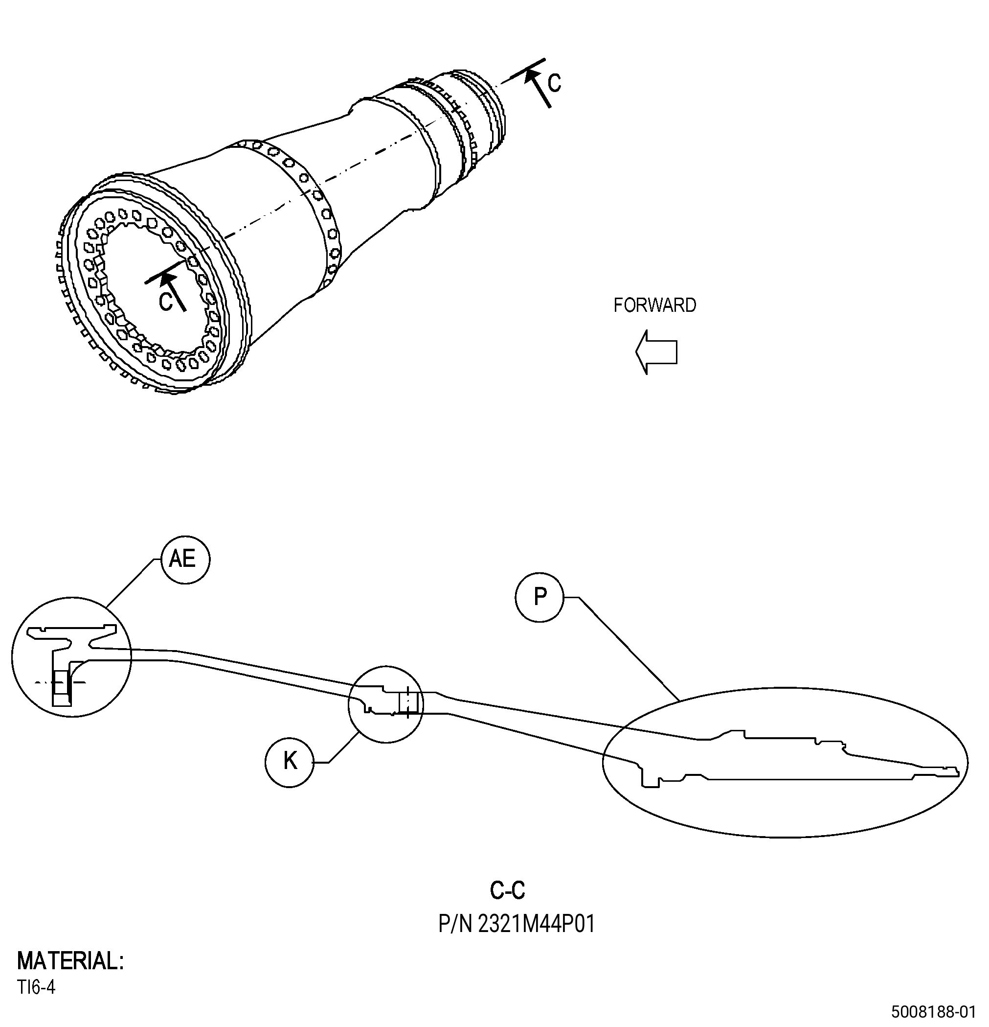
| A. | This procedure gives instructions to repair the forward fan shaft (shaft) by blending. Refer to Figure 901. |
| B. | The following maximum repairable limits apply to this repair: |
| NOTE: |
|
| (4) | Visual Inspection. |
| (a) | Do an inspection of all surfaces of the shaft (all areas unless identified in other paragraphs) for: |
| 2 | Nicks, dents, and scratches: |
| Maximum repairable limit: |
|
| (b) | Do an inspection of shaft surface Z (including chamfer) for: |
| 1 | Nicks, dents, and scratches: |
| Maximum repairable limit: |
|
| (c) | Do an inspection of area P (forward shoulder edge of sump cover seating surface) for: |
| 2 | Nicks, dents, and scratches: |
| For 2321M44P01 and 2321M44P02: |
| Maximum repairable limit: |
|
| For 2117M43P01: |
| Maximum repairable limit: |
|
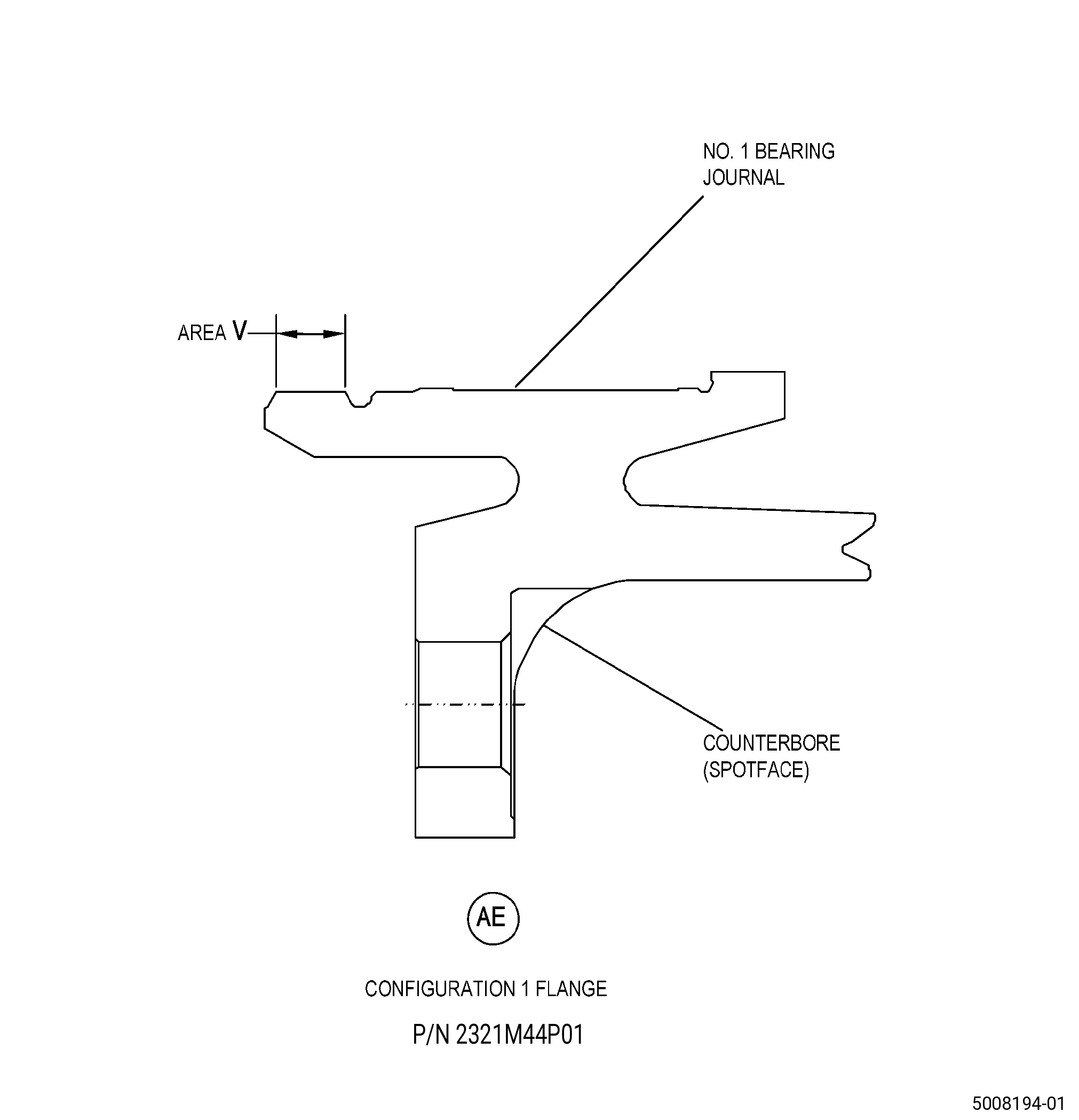
| (f) | Do an inspection of the mounting flange for: |
| 2 | Nicks, dents, scratches, and fretting on the inner diameter, scallop (configuration 1 flange only), and edge surfaces: |
| For 2321M44P01 and 2321M44P02: |
| Maximum repairable limit: |
|
| For 2117M43P01: |
| Maximum repairable limit: |
|
| 7 | Forward flange fillet for: |
| a | Nicks and dents: |
| For 2321M44P01 and 2321M44P02: |
| Maximum repairable limit: |
|
| For 2117M43P01: |
| Maximum repairable limit: |
|
| b | Scratches and fretting: |
| For 2321M44P01 and 2321M44P02: |
| Maximum repairable limit: |
|
| For 2117M43P01: |
| Maximum repairable limit: |
|
| 8 | Nicks, dents, scratches, and fretting in other areas: |
| For 2321M44P01 and 2321M44P02: |
| Maximum repairable limit: |
|
| For 2117M43P01: |
| Maximum repairable limit: |
|
| C. | The subsequent table gives a list of the part numbers that are applicable to this repair. All part numbers are applicable to all paragraphs unless specified differently. |
|
|||||||||||||||||||||||
| D. | Proprietary/Complex Process Statement. |
| (1) | None. |
| 2 . | Tools, Equipment, and Materials. |
| NOTE: |
|
| A. | Tools and Equipment. |
| (1) | Special Tools. None. |
| (2) | Standard Tools and Equipment. None. |
| (3) | Locally Manufactured Tools. None. |
| B. | Consumable Materials. |
| C. | Referenced Procedures. |
|
| D. | Expendable Parts. None. |
| E. | SPD Information. None. |
| (1) | Locally Manufactured SPD. None. |
| F. | Special Solutions. None. |
| G. | Test Specimens. None. |
| 3 . | Dimensional Information. |
| Subtask 72-24-40-220-073 |
| A. | Refer to Figure 901 for specified dimensions and locations. |
| NOTE: |
|
| NOTE: |
|
| 4 . | Setup Information. |
| None. |
| 5 . | Procedure. |
| Subtask 72-24-40-160-002 |
| A. | Clean the shaft. Refer to TASK 72-24-40-100-801 (72-24-40, CLEANING 001). |
| Subtask 72-24-40-350-003 |
| B. | Blend the shaft damaged areas. Refer to TASK 70-42-00-350-002 (BLENDING AND REMOVAL OF HIGH METAL PROCEDURES), Figure 901, and as follows: |
| (1) | Remove the minimum quantity of material until the shaft repair area agrees with the maximum repairable limits. |
| (a) | If there is no minimum blend radius specified in the maximum repairable limits, use the blend length to depth ratio. Refer to TASK 70-42-00-350-002 (BLENDING AND REMOVAL OF HIGH METAL PROCEDURES). |
| (2) | If necessary, break all sharp edges to 0.015-0.030 inch (0.39-0.76 mm). |
| Subtask 72-24-40-160-003 |
| C. | If necessary, clean the shaft. Refer to TASK 70-21-00-110-051 (CHEMICAL CLEANING) and TASK 70-21-03-160-001 (CLEANING METHOD NO. 3 - STEAM CLEANING). |
| Subtask 72-24-40-110-008 |
| D. | Etch the shaft blended areas. Refer to TASK 70-24-00-110-033 (ETCHING PROCEDURES FOR FLUORESCENT-PENETRANT INSPECTION), TASK 70-24-01-110-034 (SWAB ETCHING PROCEDURE), and as follows: |
| (1) | Use Class B etchant. |
| Subtask 72-24-40-230-002 |
| E. | Do an inspection of the shaft etched areas. Refer to TASK 70-32-00-200-002 (INDIRECT INSPECTION METHODS), TASK 70-32-03-230-002 (SPOT-FLUORESCENT-PENETRANT INSPECTION), and as follows: |
| (1) | Use Class G penetrant. |
| (2) | Refer to TASK 72-24-40-200-801 (72-24-40, INSPECTION 001) for the acceptability limits. |
| Subtask 72-24-40-140-001 |
| WARNING: |
|
| F. | If necessary, polish the shaft to remove the effects of the swab etching procedure as follows: |
| (1) | Use C10-010 abrasive cloth. |
| Subtask 72-24-40-380-002 |
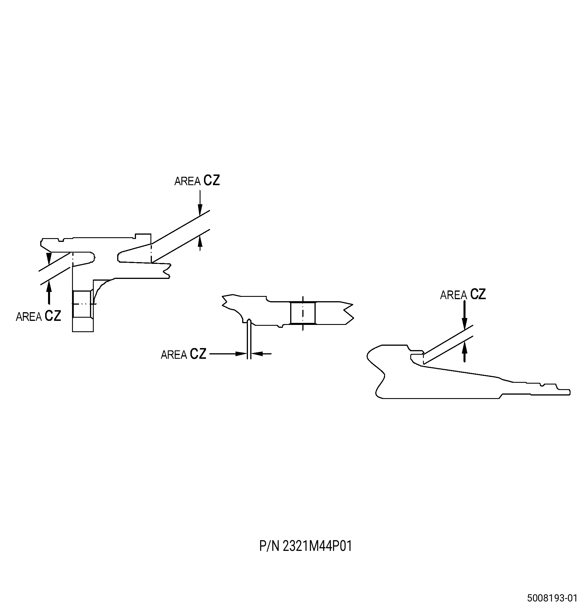
| G. | Peen the shaft repair areas. Refer to TASK 70-47-01-380-016 (SHOTPEENING), Figure 901, Figure 902, and as follows: |
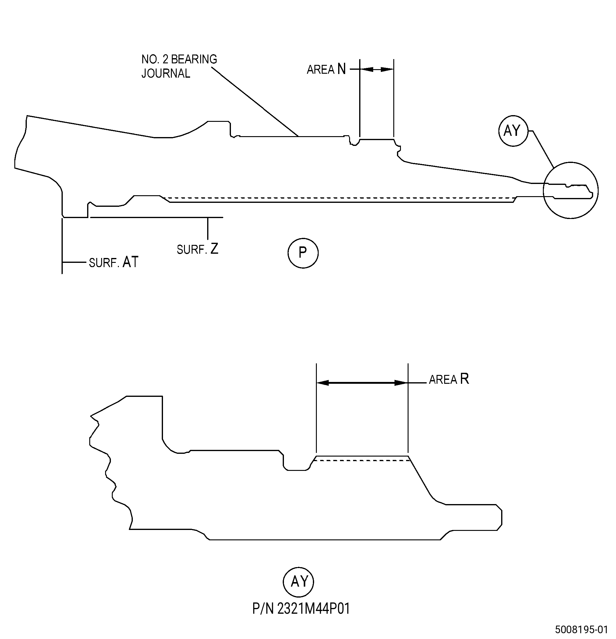
| (1) | Apply C10-021 plastic tape to area N, area R, area V, surface AT, the bearing journals, and, if necessary, to all other adjacent surfaces that are not repaired by blending. |
| (2) | Use C04-271 S110 steel shot. |
| (3) | Peen the shaft to an intensity of 0.006-0.012N. |
| (4) | Ricochet peening is permitted in area CZ of the shaft. |
| (5) | Coverage must be a minimum of 100 percent. |
| (6) | Use C10-205 Almen N test strips to make sure that the intensity is correct in the shaft repair areas. |
| (7) | Remove the plastic tape from the shaft. |
| Subtask 72-24-40-160-004 |
| H. | Clean the shaft. Refer to TASK 70-21-00-110-051 (CHEMICAL CLEANING) and TASK 70-21-03-160-001 (CLEANING METHOD NO. 3 - STEAM CLEANING). |
| Subtask 72-24-40-160-005 |
| CAUTION: |
|
| I. | Do a cleanliness inspection of the shaft repaired areas. Refer to TASK 70-22-00-100-001 (SPECIAL CLEANING PRECAUTIONS), TASK 70-22-80-160-801 (SPECIAL CLEANING PROCEDURE NO. 80 - CLEANLINESS INSPECTION), and as follows: |
| (1) | Use Class C cleanliness. |