| GENX-1B CLEANING,INSPECTION,AND REPAIR MANUAL | Dated: 02/10/2020 | |
| CIR 72-24-40 , INSPECTION 001 | ||
| FORWARD FAN SHAFT - INSPECTION | ||
| GENX-1B CLEANING,INSPECTION,AND REPAIR MANUAL | Dated: 02/10/2020 | |
| CIR 72-24-40 , INSPECTION 001 | ||
| FORWARD FAN SHAFT - INSPECTION | ||
| * * * FOR ALL |
| TASK 72-24-40-200-801 |
| 1 . | General. |
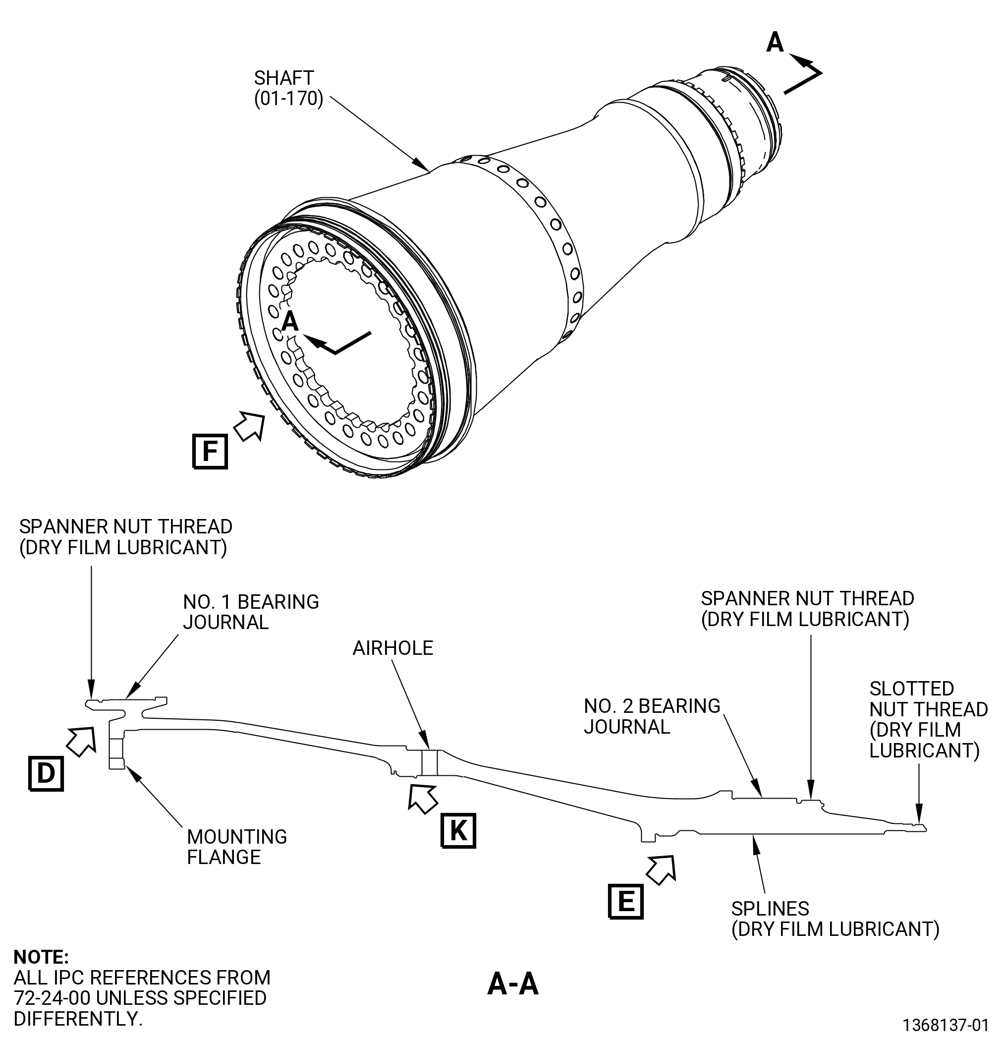
| A. | This procedure gives instructions to do an inspection of the forward fan shaft (shaft). Refer to Figure 801. |
| • |
|
| • |
|
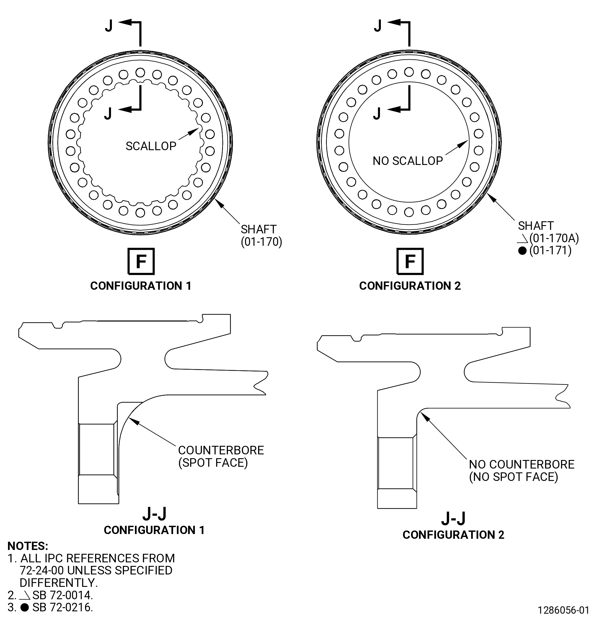
| B. | There are two configurations for the shaft. The difference is in the shaft mounting flange. The configuration 1 shaft (01-170 , 72-24-00) (SIN 81002) contains a scalloped flange with a counterbore (spot face) on the aft side of the flange. The configuration 2 shaft (01-170A , 72-24-00) (SIN 81002) and (01-171 , 72-24-00) (SIN 81002) does not contain a spot face. |
| 2 . | Tools, Equipment, and Materials. |
| NOTE: |
|
| A. | Tools and Equipment. |
| (1) | Special Tools. None. |
| (2) | Standard Tools and Equipment. |
| (3) | Locally Manufactured Tools. None. |
| B. | Consumable Materials. |
|
| C. | Referenced Procedures. |
|
| D. | Expendable Parts. None. |
| 3 . | Specific Inspection Procedure. |
| Subtask 72-24-40-230-001 |
| A. | Remove the dry film lubricant from the spline teeth and threads. Refer to TASK 72-24-40-300-801 (72-24-40, REPAIR 001). |
| B. | Do a Class G fluorescent penetrant inspection of the shaft. Refer to TASK 70-32-02-230-001 (FLUORESCENT PENETRANT INSPECTION). |
| • |
|
| Subtask 72-24-40-110-004 |
| C. | Do an eddy current inspection of the vent holes of the shaft as follows: |
| CAUTION: |
|
| (1) | Clean the shaft. Refer to TASK 72-24-40-100-801 (72-24-40, Cleaning 001). |
| NOTE: |
|
| (2) | If necessary, mechanically clean the vent hole surfaces. Refer to TASK 70-22-06-110-043 (SPECIAL CLEANING PROCEDURE 6 - BOLTHOLE CLEANING FOR EDDY CURRENT INSPECTION). |
| Subtask 72-24-40-250-001 |
| (3) | Do an eddy current inspection of the vent holes. Refer to TASK 70-32-07-250-001 (HIGH SPEED AND SLOW SPEED EDDY CURRENT INSPECTION OF CIRCULAR HOLES IN INCONEL OR TITANIUM ENGINE PARTS). |
| NOTE: |
|
| NOTE: |
|
| (a) | Do an eddy current inspection of the shaft vent holes as follows: |
| 1 | Use the GE-FQAP-621 inspection kit with either the GE-FQAP-302 inspection kit, GE-FQAP-302A inspection kit, GE-FQAP-302B inspection kit, or GE- FQAP-302C inspection kit. |
| 2 | Use the following filter settings for the equipment used to do the eddy current inspection: |
|
| (b) | Eddy current inspection evaluation limits. |
| 1 | For high speed eddy current inspection, the evaluation limit is four major divisions. |
| (c) | Eddy current inspection reject limits. |
| 1 | For high speed eddy current inspection, the rejection limit is four major divisions after the evaluation is complete. |
| (d) | All shafts that are rejected by the limits in Subtask 72-24-40-250-001 (paragraph C.(3)(c)) are not serviceable. All shafts that are not rejected by the limits in Subtask 72-24-40-250-001 (paragraph C.(3)(c)) are serviceable. |
| (e) | Make sure that all records that were made during the eddy current inspection are as complete as possible. Permanently keep these records for each shaft that was inspected. |
| 4 . | Visual Inspection. |
| Refer to Figure 801. |
| Subtask 72-24-40-220-002 |
| A. | Do an inspection of all surfaces of the shaft (all areas unless identified in other paragraphs) for: |
| (1) | Cracks: |
| Maximum serviceable limit: |
|
| Repair method: |
|
| Subtask 72-24-40-220-003 |
| (2) | Nicks, dents, and scratches: |
| Maximum serviceable limit: |
|
| Maximum repairable limit: |
|
| Repair method: |
|
| Subtask 72-24-40-220-068 |
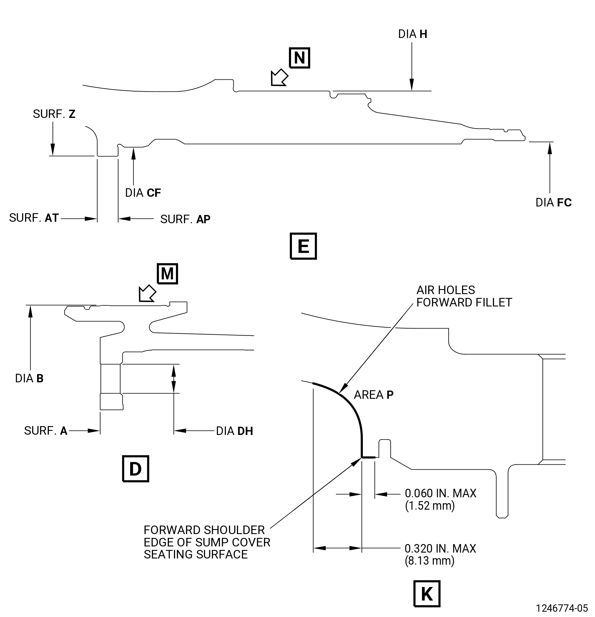
| B. | Do an inspection of shaft surface Z (including chamfer) for: |
| (1) | Nicks, dents, and scratches: |
| Maximum serviceable limit: |
|
| Maximum repairable limit: |
|
| Repair method: |
|
| Subtask 72-24-40-220-071 |
| C. | Do an inspection of area P (forward shoulder edge of sump cover seating surface) for: |
| (1) | Cracks: |
| Maximum serviceable limit: |
|
| Repair method: |
|
| Subtask 72-24-40-220-072 |
| (2) | Nicks, dents, and scratches: |
| Maximum serviceable limit: |
|
| Maximum repairable limit: |
|
| Repair method: |
|
| Subtask 72-24-40-220-004 |
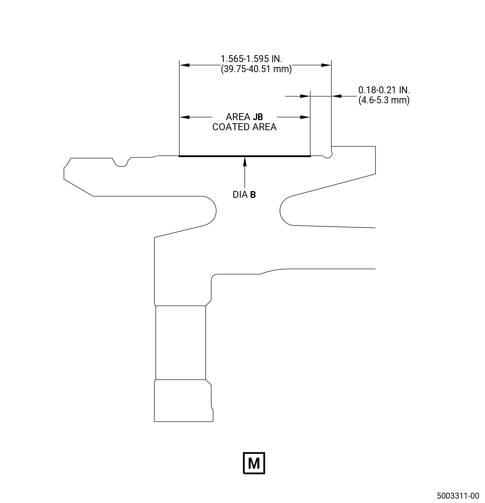
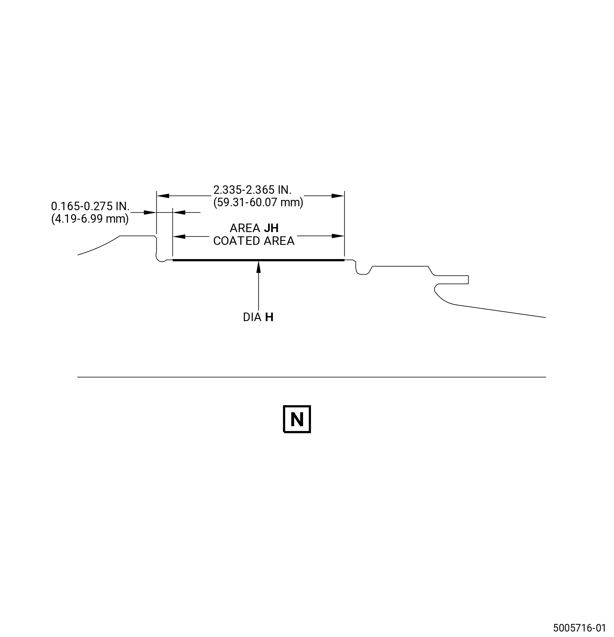
| D. | Do an inspection of the No. 1 and No. 2 bearing journals for: |
| (1) | Wear on diameter B or diameter H: |
| Maximum serviceable limit: |
|
| Repair method: |
|
| Subtask 72-24-40-220-005 |
| (2) | Nicks, dents, and scratches: |
| Maximum serviceable limit: |
|
| Repair method: |
|
| Subtask 72-24-40-220-006 |
| (3) | Fretting: |
| Maximum serviceable limit: |
|
| Repair method: |
|
| Subtask 72-24-40-220-007 |
| E. | Do an inspection of the spanner nut threads for: |
| (1) | Damage: |
| Maximum serviceable limit: |
|
| Maximum repairable limit: |
|
| Repair method: |
|
| Subtask 72-24-40-220-008 |
| F. | Do an inspection of the mounting flange for: |
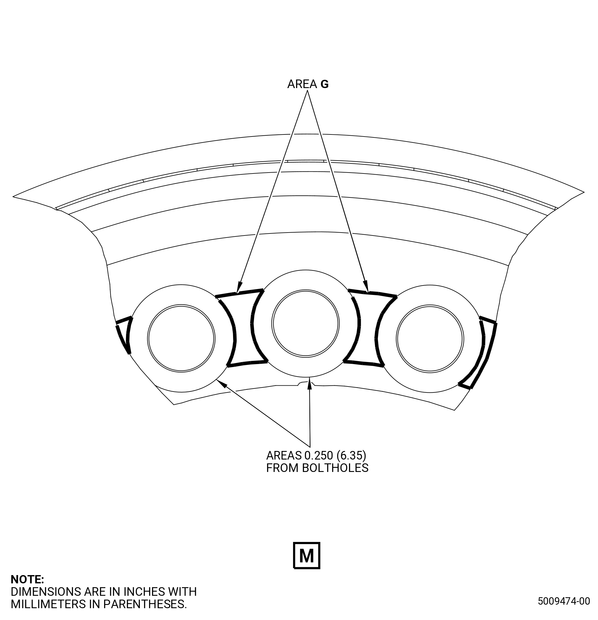
| (1) | Nicks, dents, scratches, and fretting in the area 0.250 inch (6.35 mm) from the boltholes on the forward and aft flange surfaces: |
| Maximum serviceable limit: |
|
| Maximum repairable limit: |
|
| Repair method: |
|
| Subtask 72-24-40-220-009 |
| (2) | Nicks, dents, scratches, and fretting on the inner diameter, scallop (configuration 1 flange only), and edge surfaces: |
| Maximum serviceable limit: |
|
| Maximum repairable limit: |
|
| Repair method: |
|
| Subtask 72-24-40-220-010 |
| (3) | Deleted. |
| Subtask 72-24-40-220-011 |
| (4) | Fretting on the mating face: |
| Maximum serviceable limit: |
|
| Repair method: |
|
| Subtask 72-24-40-220-012 |
| (5) | Fretting on the aft surface from bolthead contact: |
| Maximum serviceable limit: |
|
| Repair method: |
|
| Subtask 72-24-40-220-074 |
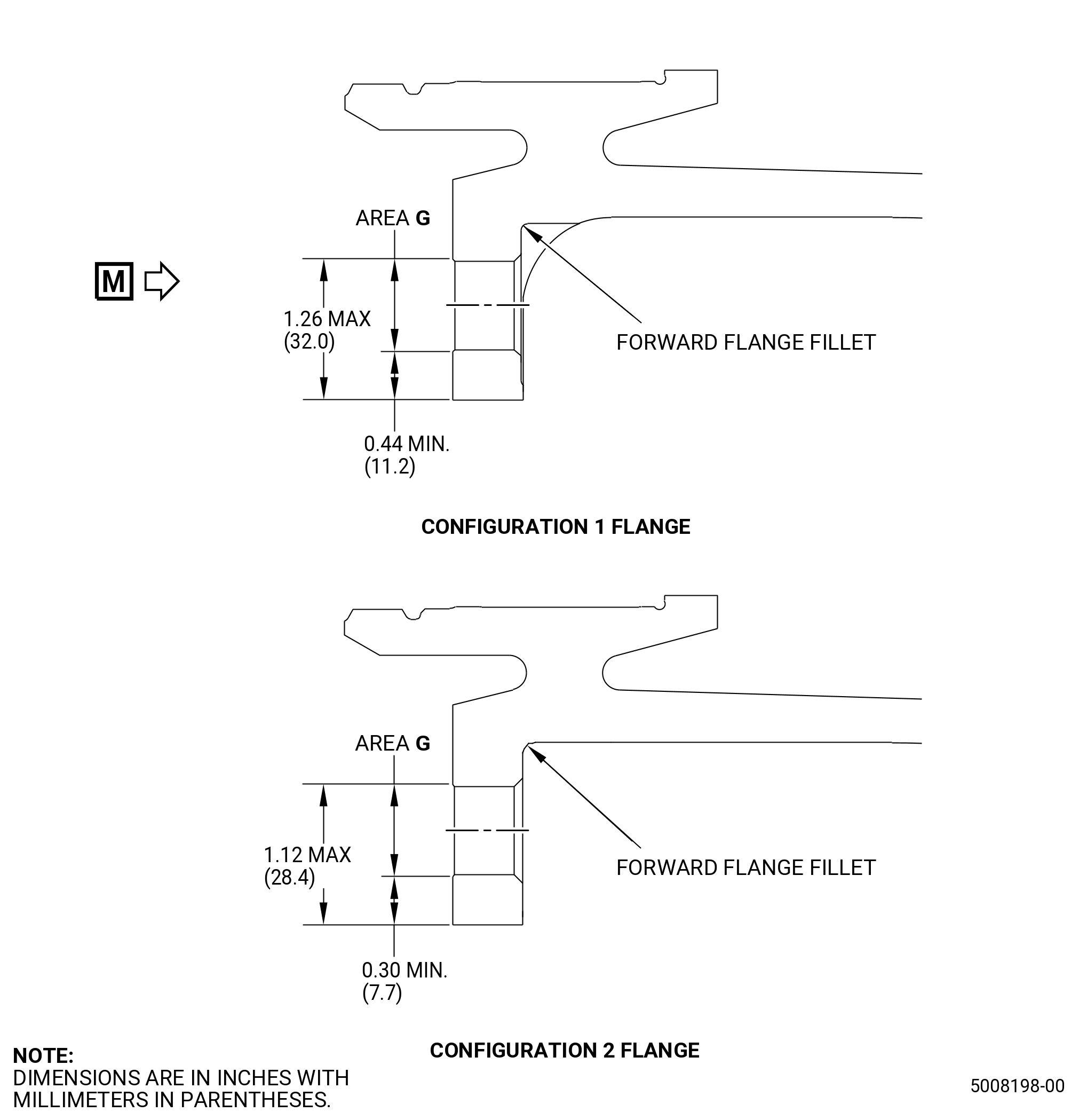
| (6) | Nicks, dents, scratches, and fretting in area G: |
| Maximum serviceable limit: |
|
| Repair method: |
|
| Subtask 72-24-40-220-075 |
| (7) | Forward flange fillet for: |
| (a) | Nicks and dents: |
| Maximum serviceable limit: |
|
| Repair method: |
|
| Subtask 72-24-40-220-076 |
| (b) | Scratches and fretting: |
| Maximum serviceable limit: |
|
| Repair method: |
|
| Subtask 72-24-40-220-077 |
| (8) | Nicks, dents, scratches, and fretting in other areas: |
| Maximum serviceable limit: |
|
| Maximum repairable limit: |
|
| Repair method: |
|
| Subtask 72-24-40-220-013 |
| G. | Do an inspection of the boltholes for: |
| (1) | Galling or scratches: |
| Maximum serviceable limit: |
|
| Repair method: |
|
| Subtask 72-24-40-220-014 |
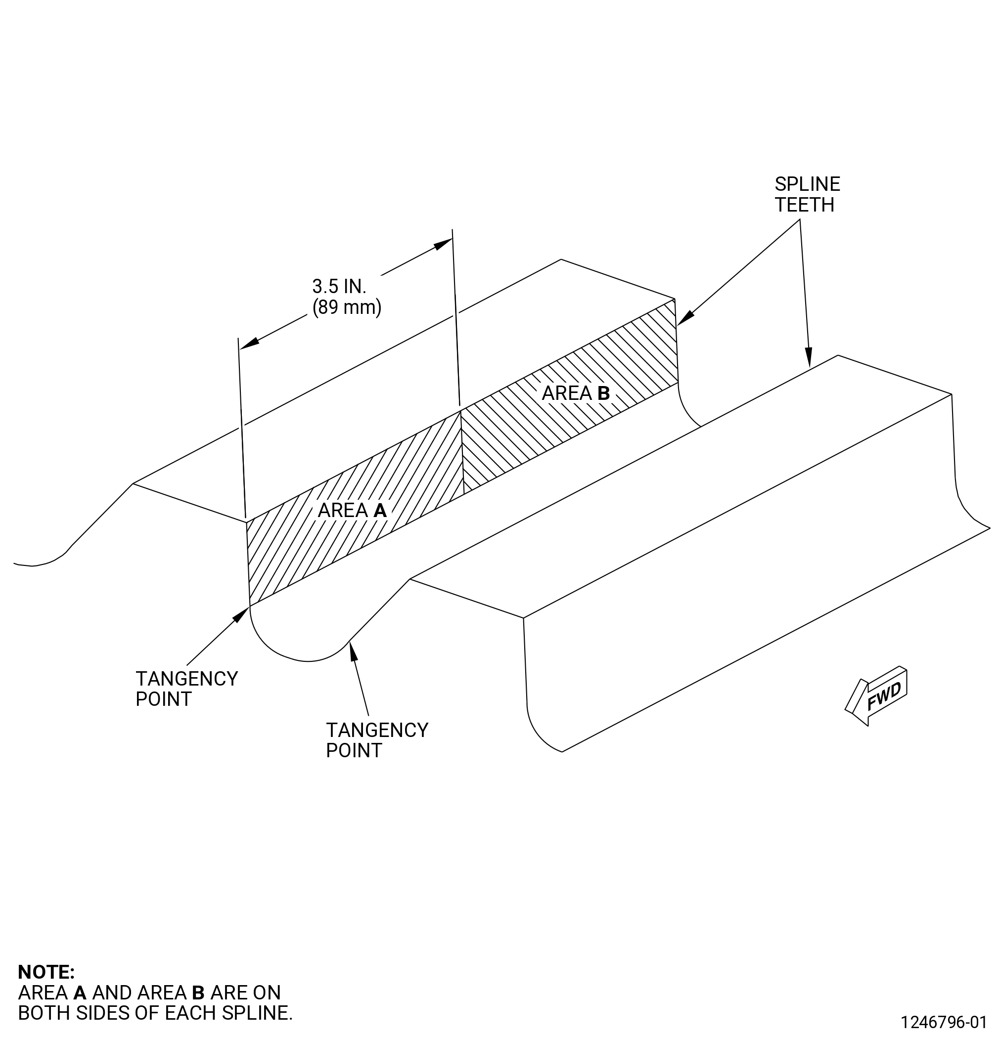
| H. | Do an inspection of the splines as follows. Refer to Figure 802. |
| (1) | Area A for: |
| (a) | Nicks and scratches: |
| Maximum serviceable limit: |
|
| Repair method: |
|
| Subtask 72-24-40-220-015 |
| (b) | Fretting: |
| Maximum serviceable limit: |
|
| Repair method: |
|
| Subtask 72-24-40-220-016 |
| (c) | High metal: |
| Maximum serviceable limit: |
|
| Maximum repairable limit: |
|
| Repair method: |
|
| Subtask 72-24-40-220-017 |
| (2) | Area B for: |
| (a) | Nicks and scratches: |
| Maximum serviceable limit: |
|
| Repair method: |
|
| Subtask 72-24-40-220-018 |
| (b) | Fretting: |
| Maximum serviceable limit: |
|
| Repair method: |
|
| Subtask 72-24-40-220-019 |
| (c) | High metal: |
| Maximum serviceable limit: |
|
| Maximum repairable limit: |
|
| Repair method: |
|
| Subtask 72-24-40-220-078 |
| (3) | Root fillet for: |
| (a) | Nicks and dents: |
| Maximum serviceable limit: |
|
| Repair method: |
|
| Subtask 72-24-40-220-079 |
| (b) | Scratches: |
| Maximum serviceable limit: |
|
| Repair method: |
|
| Subtask 72-24-40-220-020 |
| (4) | All other spline areas for: |
| (a) | Nicks and scratches: |
| Maximum serviceable limit: |
|
| Repair method: |
|
| Subtask 72-24-40-220-021 |
| I. | Do an inspection of the shaft coupling nut seating surface (surface AT) as follows. Refer to Figure 801. |
| (1) | Nicks, dents, scratches, and fretting: |
| Maximum serviceable limit: |
|
| Repair method: |
|
| Subtask 72-24-40-220-022 |
| J. | Do an inspection of the fan mid shaft seating surface (surface AP) for: |
| (1) | Fretting: |
| Maximum serviceable limit: |
|
| Repair method: |
|
| Subtask 72-24-40-220-023 |
| K. | Do an inspection of the shaft aft pilot diameter (diameter FC) for: |
| (1) | Wear, fretting, and galling on the fan mid shaft contact area of the pilot: |
| Maximum serviceable limit: |
|
| Repair method: |
|
| Subtask 72-24-40-220-058 |
| L. | Do an inspection of the shaft forward pilot (diameter CF) for: |
| (1) | Galling on pilot: |
| Maximum serviceable limit: |
|
| Repair method: |
|
| Subtask 72-24-40-220-066 |
| M. | Do an inspection of the dry film lubricant for: |
| (1) | Missing dry film lubricant: |
| Maximum serviceable limit: |
|
| Repair method: |
|
| Subtask 72-24-40-220-080 |
| N. | Do an inspection of the airhole (chamfer included) as follows: |
| (1) | Cracks: |
| Maximum serviceable limit: |
|
| Repair method: |
|
| Subtask 72-24-40-220-081 |
| (2) | Nicks and dents: |
| Maximum serviceable limit: |
|
| Repair method: |
|
| Subtask 72-24-40-220-082 |
| (3) | Scratches: |
| Maximum serviceable limit: |
|
| Repair method: |
|
| 5 . | Dimensional Inspection. |
| Refer to Figure 801. |
| Subtask 72-24-40-220-059 |
| A. | Do an inspection of the shaft for: |
| (1) | Mounting boltholes (diameter DH): |
| Minimum serviceable limit: |
|
| Maximum serviceable limit: |
|
| Repair method: |
|
| Subtask 72-24-40-220-060 |
| (2) | No. 1 bearing journal (diameter B measured only on area JB): |
| Minimum serviceable limit: |
|
| Maximum serviceable limit: |
|
| Repair method: |
|
| Subtask 72-24-40-220-061 |
| (3) | No. 2 bearing journal (diameter H measured only on area JH): |
| Minimum serviceable limit: |
|
| Maximum serviceable limit: |
|
| Repair method: |
|
| Subtask 72-24-40-220-062 |
| (4) | Shaft forward pilot diameter (diameter CF): |
| NOTE: |
|
| Minimum serviceable limit: |
|
| Maximum serviceable limit: |
|
| Repair method: |
|
| Subtask 72-24-40-220-063 |
| (5) | Shaft aft pilot diameter (diameter FC): |
| NOTE: |
|
| Minimum serviceable limit: |
|
| Maximum serviceable limit: |
|
| Repair method: |
|
| Subtask 72-24-40-220-064 |
| (6) | Surface A in relation to surface AP: |
| NOTE: |
|
| Minimum serviceable limit: |
|
| Maximum serviceable limit: |
|
| Repair method: |
|
| Subtask 72-24-40-220-065 |
| (7) | Runout of diameter H in relation to diameter B: |
| Minimum serviceable limit: |
|
| Maximum serviceable limit: |
|
| Repair method: |
|
| 6 . | Apply Dry Film Lubricant to the Threads and Splines |
| Subtask 72-24-40-640-001 |
| A. | If necessary, apply C02-088 dry film lubricant to the threads and splines of the shaft. Refer to TASK 72-24-40-300-801 (72-24-40, REPAIR 001). |