| GENX-1B CLEANING,INSPECTION,AND REPAIR MANUAL | Dated: 09/09/2020 | |
| CIR 72-24-40 , REPAIR 004 | ||
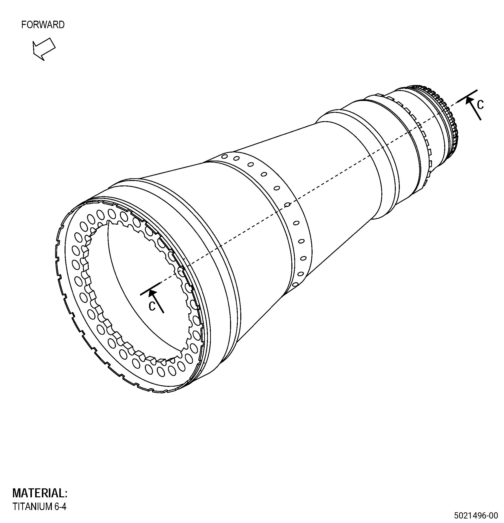
| FORWARD FAN SHAFT - REPAIR - THERMAL SPRAY REPAIR OF PILOT DIAMETER FC/DIAMETER CF | ||
| GENX-1B CLEANING,INSPECTION,AND REPAIR MANUAL | Dated: 09/09/2020 | |
| CIR 72-24-40 , REPAIR 004 | ||
| FORWARD FAN SHAFT - REPAIR - THERMAL SPRAY REPAIR OF PILOT DIAMETER FC/DIAMETER CF | ||
| * * * FOR ALL |
| TASK 72-24-40-300-804 |
| 1 . | Thermal Spray Repair of Pilot Diameter FC/Diameter CF. |
| A. | This procedure gives instructions to repair the forward fan shaft (shaft) by thermal spraying the pilot diameter FC/diameter CF. Refer to Figure 901. |
| NOTE: |
|
| B. | The following maximum repairable limits apply to this repair: |
| NOTE: |
|
| NOTE: |
|
| (4) | Visual Inspection. |
| (k) | Do an inspection of the shaft aft pilot diameter (diameter FC) for: |
| 1 | Wear, fretting, and galling on the fan mid shaft contact area of the pilot: |
| Maximum repairable limit: |
|
| (l) | Do an inspection of the shaft forward pilot (diameter CF) for: |
| 1 | Galling on pilot: |
| Maximum repairable limit: |
|
| (5) | Dimensional Inspection. |
| (a) | Do an inspection of the shaft for: |
| 4 | Shaft forward pilot diameter (diameter CF): |
| Maximum repairable limit: |
|
| 5 | Shaft aft pilot diameter (diameter FC): |
| Maximum repairable limit: |
|
| C. | The subsequent table gives a list of the part numbers that are applicable to this repair. All part numbers are applicable to all paragraphs unless specified differently. |
|
|||||||||||||||||||||||
| D. | Proprietary/Complex Process Statement. |
| (1) | None. |
| 2 . | Tools, Equipment, and Materials. |
| NOTE: |
|
| A. | Tools and Equipment. |
| (1) | Special Tools. None. |
| (2) | Standard Tools and Equipment. None. |
| (3) | Locally Manufactured Tools. None. |
| B. | Consumable Materials. |
| C. | Referenced Procedures. |
|
| D. | Expendable Parts. None. |
| E. | SPD Information. |
| (1) | Locally Manufactured SPD. None. |
| F. | Special Solutions. None. |
| G. | Test Specimens. Refer to TASK 70-49-21-340-022 (THERMAL SPRAYING NICKEL-CHROMIUM/ALUMINUM COMPOSITE (POWDER)) and TASK 70-49-28-340-029 (THERMAL SPRAYING TUNGSTEN CARBIDE (POWDER)) . |
| 3 . | Dimensional Information. |
| Subtask 72-24-40-220-094 |
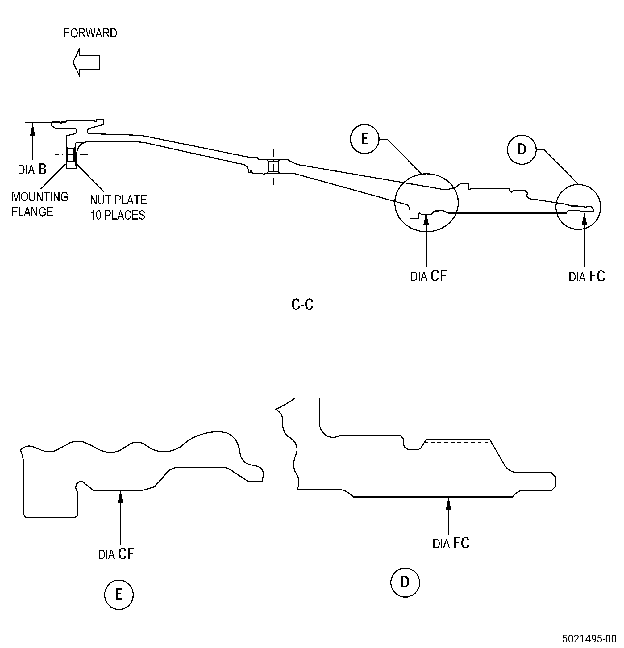
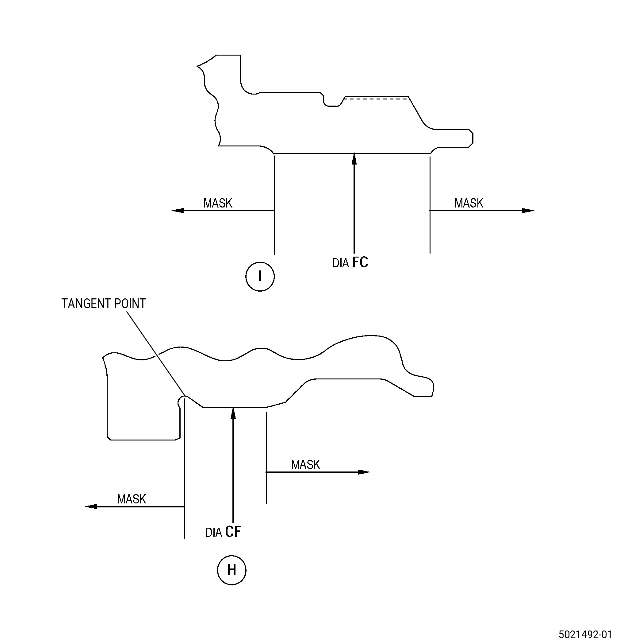
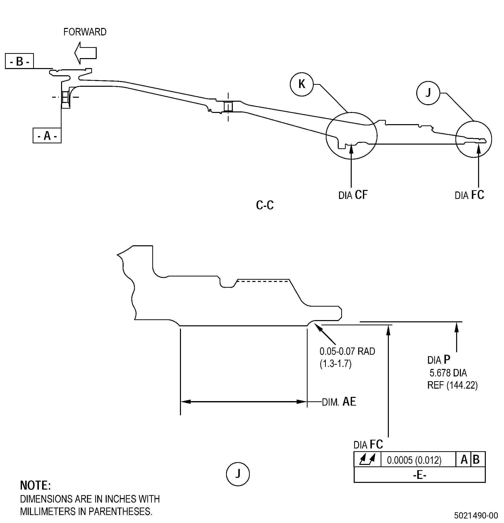
| A. | Refer to Figure 901 and Figure 904 for specified dimensions and locations. |
| NOTE: |
|
| NOTE: |
|
|
| 4 . | Setup Information. |
| Subtask 72-24-40-350-011 |
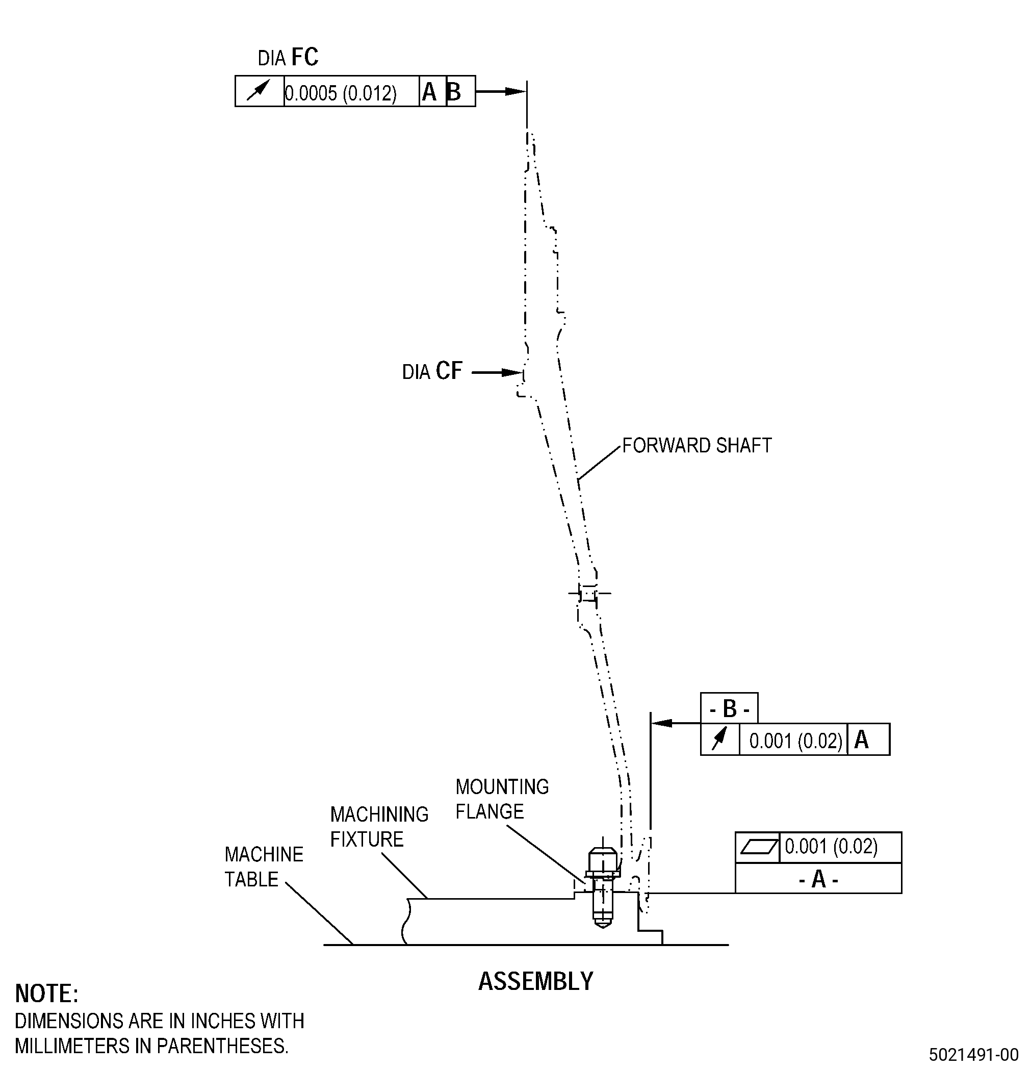
| A. | Set-up the shaft for machining. Refer to Figure 903 and as follows: |
| (1) | Set-up the shaft to machine the pilot diameter FC and as follows: |
| (a) | Install the shaft mounting flange on the machining fixture/machine table as follows: |
| Subtask 72-24-40-350-012 |
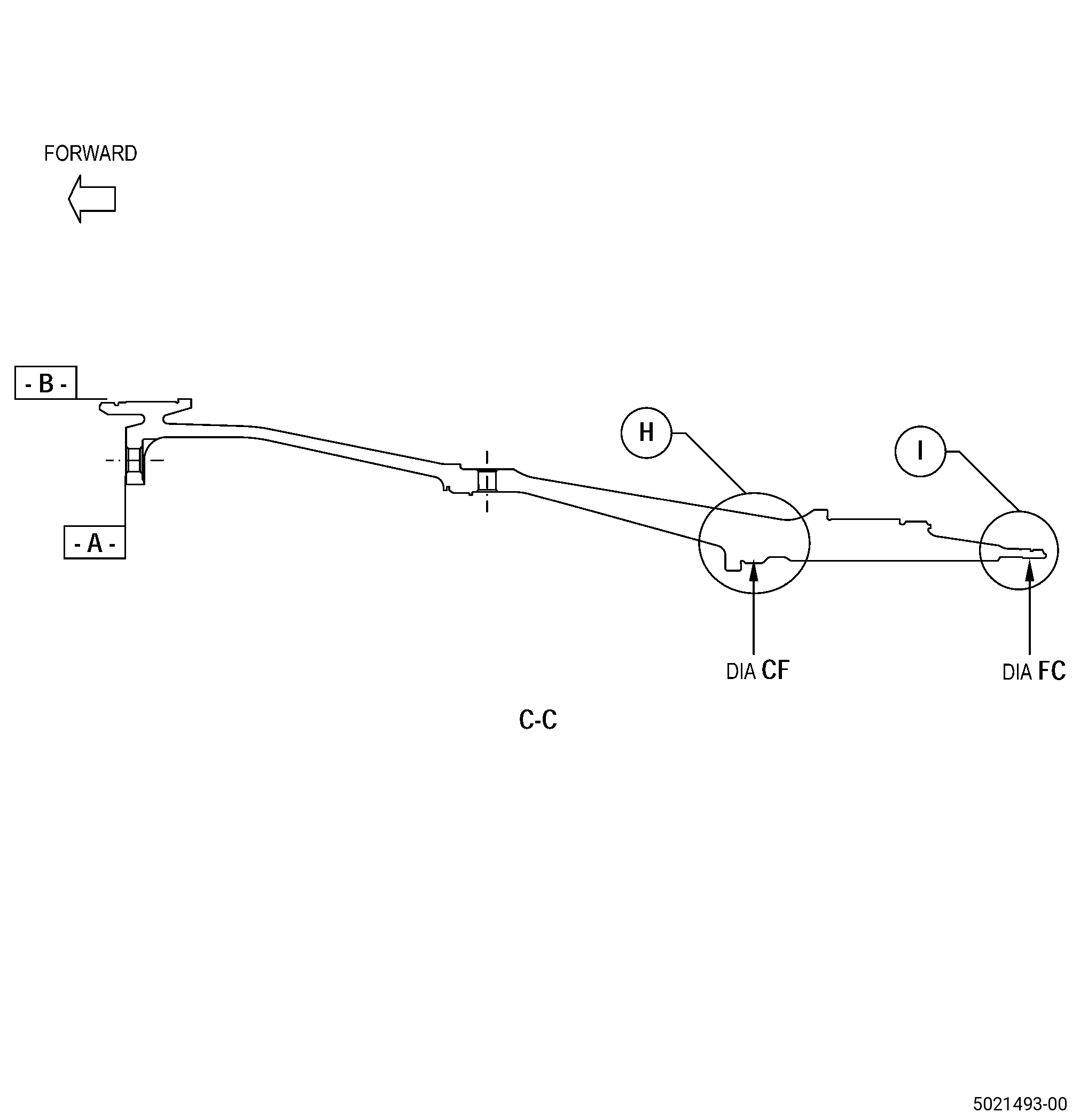
| 1 | The flatness of surface A must be 0.001 inch (0.02 mm) or less. |
| 2 | The runout of diameter B must be 0.001 inch (0.02 mm) or less. |
| (b) | Use bolts to attach the shaft to the machining fixture/machine table as follows: |
| Subtask 72-24-40-350-013 |
| 1 | Install the bolts in each second flange bolt hole. |
| (c) | If necessary, do Subtask 72-24-40-350-012 (paragraph 4.A.(1)(a)1) and Subtask 72-24-40-350-013 (paragraph 4.A.(1)(b)1) again to get the runout of diameter B. |
| (2) | Set-up the shaft to machine the pilot diameter CF and as follows: |
| (a) | Install the shaft mounting flange on the machining fixture/machine table as follows: |
| Subtask 72-24-40-350-014 |
| 1 | The flatness of surface A must be 0.001 inch (0.02 mm) or less. |
| 2 | The runout of diameter B must be 0.001 inch (0.02 mm) or less. |
| 3 | The total runout of diameter FC must be 0.0005 inch (0.012 mm) or less. |
| (b) | Use bolts to attach the shaft to the machining fixture/machine table as follows: |
| Subtask 72-24-40-350-015 |
| 1 | Install the bolts in each second flange bolt hole. |
| (c) | If necessary, do Subtask 72-24-40-350-014 (paragraph 4.A.(2)(a)1) thru Subtask 72-24-40-350-015 (paragraph 4.A.(2)(b)1) again to get the flatness of surface A, runout of diameter B, and runout of diameter FC. |
| 5 . | Procedure. |
| Subtask 72-24-40-160-010 |
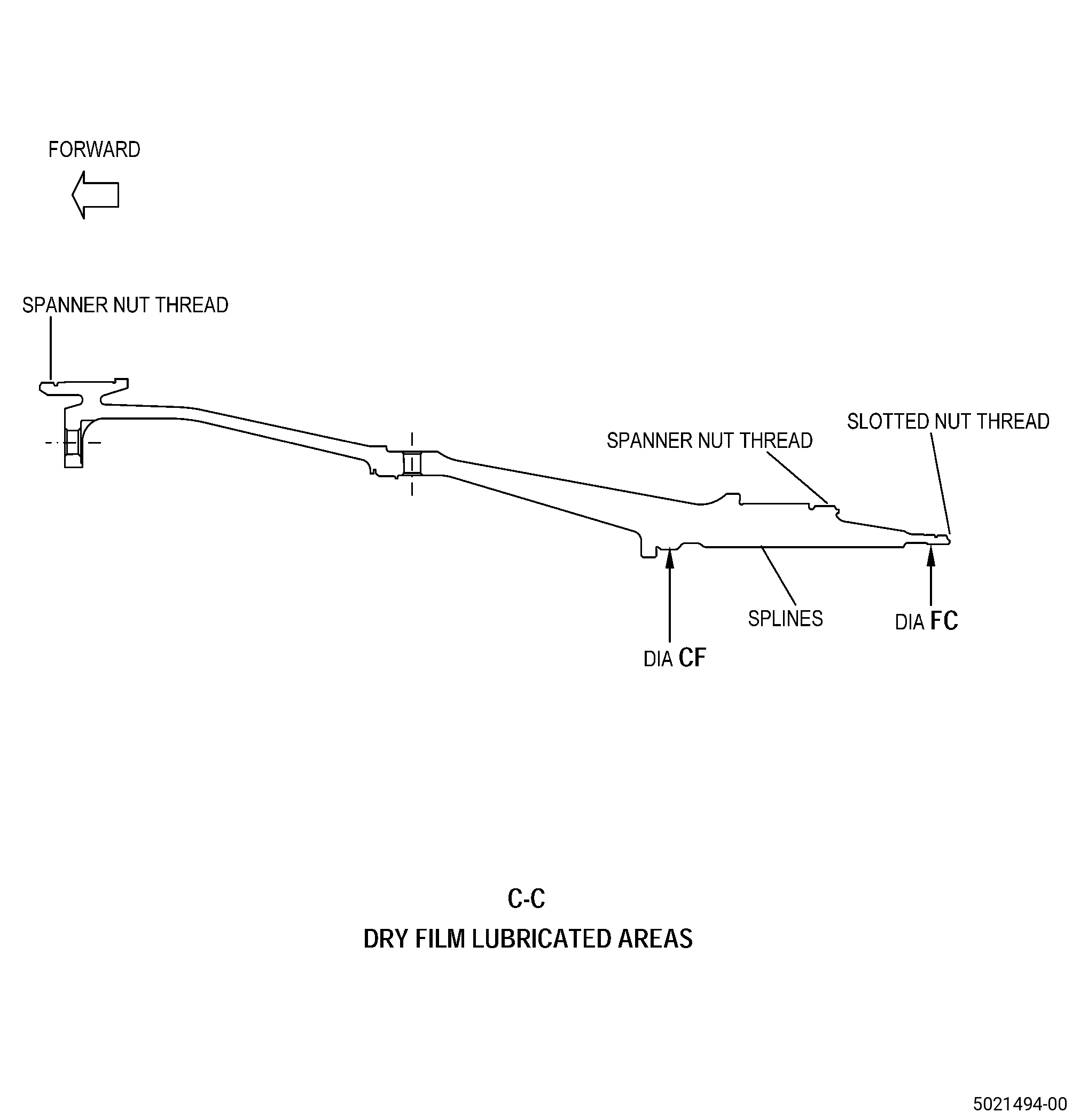
| A. | If necessary, remove the dry film lubricant from the spline teeth and threads of the shaft. Refer to TASK 72-24-40-200-801 (72-24-40, INSPECTION 001) and Figure 901. |
| Subtask 72-24-40-160-011 |
| B. | If necessary, clean the shaft. Refer to TASK 72-24-40-100-801 (72-24-40, CLEANING 001). |
| Subtask 72-24-40-220-095 |
| C. | Do a visual inspection of the shaft pilot diameter FC/diameter CF. Refer to Figure 901 and as follows: |
| (1) | If there is thermal spray coating, do Subtask 72-24-40-330-002 (paragraph 5.D.). |
| (2) | If there is no thermal spray coating, do Subtask 72-24-40-160-012 (paragraph 5.E.). |
| Subtask 72-24-40-330-002 |
| D. | Alternative Procedure Available. Remove the thermal spray coating from the shaft pilot diameter FC/diameter CF. Refer to TASK 70-23-00-100-001 (STRIPPING PROCEDURES), TASK 70-23-23-330-008 (REMOVAL OF COATINGS BY HIGH PRESSURE WATER STRIPPING), Figure 901, and Figure 902. |
| Subtask 72-24-40-320-004 |
| CAUTION: |
|
| D.A. | Alternative Procedure. Machine the shaft pilot diameter FC/diameter CF to remove the thermal spray coating. Refer to TASK 70-00-03-800-004 (MACHINING DATA), Subtask 72-24-40-220-094 (paragraph 3.A.), Figure 901, and Figure 902. |
| (1) | Set-up the shaft to machine diameter FC/diameter CF. Refer to Subtask 72-24-40-350-011 (paragraph 4.A.). |
| Subtask 72-24-40-160-012 |
| E. | If necessary, clean the shaft. Refer to TASK 72-24-40-100-801 (72-24-40, CLEANING 001). |
| Subtask 72-24-40-220-096 |
| F. | Do a visual inspection of the shaft pilot diameter FC/diameter CF for parent metal wear as follows: |
| (1) | Use 10X magnification. |
| (2) | If the pilot diameter FC/diameter CF has parent metal wear, do Subtask 72-24-40-320-005 (paragraph 5.G.). |
| (3) | If the pilot diameter FC or diameter CF do not have parent material wear, measure to make sure it is within the in-process limits. Refer to Subtask 72-24-40-220-094 (paragraph 3.A.) and as follows: |
| (a) | If the pilot diameter FC or diameter CF are more than the maximum in-process limits then the shaft cannot be repaired by this procedure. |
| Subtask 72-24-40-320-005 |
| CAUTION: |
|
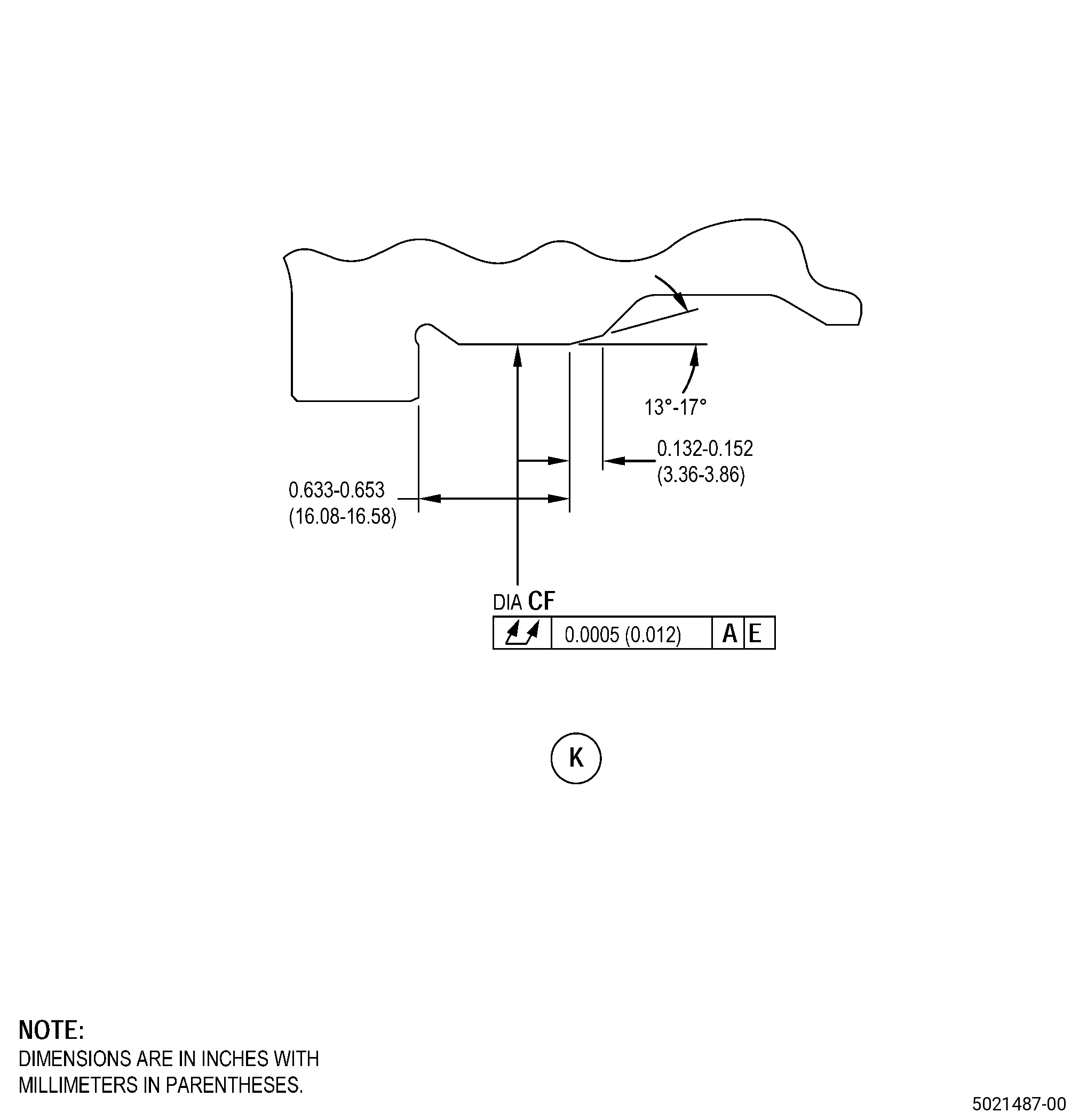
| G. | Machine the shaft pilot diameter FC/diameter CF. Refer to TASK 70-00-03-800-004 (MACHINING DATA), Subtask 72-24-40-220-094 (paragraph 3.A.), Figure 904, and as follows: |
| (1) | Set-up the shaft to machine diameter FC/diameter CF. Refer to Subtask 72-24-40-350-011 (paragraph 4.A.). |
| (2) | Machine the shaft pilot diameter FC/diameter CF to the in-process dimensions and as follows: |
| (a) | If necessary, remove all parent metal wear from the shaft. |
| NOTE: |
|
| (b) | The final surface finish must be 90 microinches (2.3 micrometers). |
| (c) | Break all sharp edges to 0.015-0.030 inch (0.39-0.76 mm). |
| (3) | Remove the shaft from the machining fixture/machine table. |
| Subtask 72-24-40-110-010 |
| H. | Etch the shaft pilot diameter FC/diameter CF. Refer to TASK 70-24-00-110-033 (ETCHING PROCEDURES FOR FLUORESCENT-PENETRANT INSPECTION), TASK 70-24-01-110-034 (SWAB ETCHING PROCEDURE), and as follows: |
| (1) | Use Class B etchant. |
| Subtask 72-24-40-230-005 |
| I. | Do an inspection of the shaft pilot diameter FC/diameter CF. Refer to TASK 70-32-00-200-002 (INDIRECT INSPECTION METHODS), TASK 70-32-03-230-002 (SPOT-FLUORESCENT-PENETRANT INSPECTION), and as follows: |
| (1) | Use Class G penetrant. |
| (2) | Linear indications are not permitted. |
| NOTE: |
|
| (3) | Indications that are 0.015 inch (0.38 mm) or less are permitted. |
| Subtask 72-24-40-110-011 |
| J. | Clean the shaft pilot diameter FC/diameter CF as follows: |
| WARNING: |
|
| (1) | Clean the shaft pilot diameter FC/diameter CF with a C10-182 cleaning cloth moist with C04-035 isopropyl alcohol and do as follows: |
| (a) | Replace the dirty clothes with a C10-182 cleaning cloth until the last moist cloth stays clean. |
| Subtask 72-24-40-380-004 |
| K. | Peen the shaft pilot diameter FC/diameter CF. Refer to TASK 70-47-01-380-016 (SHOTPEENING), Figure 902, and as follows: |
| (1) | Apply C10-021 plastic tape to the shaft that you will not peen. |
| (2) | Use C04-271 S110 cast steel shot. |
| (3) | Peen the shaft to an intensity of 6-12N and as follows: |
| (a) | Make sure that you do the intensity verification in a simulative fixture. |
| (4) | Use C10-205 Almen test strips and an Almen strip holder to measure the intensity at pilot diameter FC/diameter CF. |
| (5) | Overspray is permitted on all areas, but not on threads and on thermal spray coated areas. |
| (6) | Use a minimum impingement angle of 35 degrees. |
| (7) | Remove the plastic tape from the shaft pilot diameter FC/diameter CF. |
| Subtask 72-24-40-160-013 |
| WARNING: |
|
| (8) | Use clean, dry shop air to remove the remaining dust and particles from the shaft. |
| Subtask 72-24-40-220-098 |
| L. | Do a dimensional inspection of the in-process limits of diameter FC for the application of a bond coat and top coat or the application of only a top coat to restore diameter FC to the finish limits, use the table below as follows: |
|
| Subtask 72-24-40-340-003 |
| WARNING: |
|
| M. | Thermal-spray the shaft (diameter FC) and the test specimens. Refer to TASK 70-49-00-340-001 (THERMAL SPRAYING), TASK 70-49-21-340-022 (THERMAL SPRAYING NICKEL-CHROMIUM/ALUMINUM COMPOSITE (POWDER)), Figure 901, and as follows: |
| (1) | Apply C10-012 masking tape to the areas adjacent to diameter FC. Refer to Figure 902. |
| (2) | Do the preliminary operations specified in TASK 70-49-00-340-001 (THERMAL SPRAYING), use the surface roughness limits for the titanium base material. |
| (3) | Overspray is not permitted. |
| (4) | Apply the bond coat to the shaft (diameter FC) and the test specimens at the same time, same distance, same angle, and to the same as-sprayed thickness of 0.004-0.008 inch (0.11-0.20 mm) and do as follows: |
| (a) | Apply a sufficient quantity of bond coat to make a final top coat thickness of 0.0095-0.0120 inch (0.242-0.304 mm) after machining. Refer to Subtask 72-24-40-220-094 (paragraph 3.A.). |
| (5) | Do all quality assurance testing specified in TASK 70-49-21-340-022 (THERMAL SPRAYING NICKEL-CHROMIUM/ALUMINUM COMPOSITE (POWDER)). |
| (a) | Do the metallography test to make sure that the bond coat meets the quality requirements. |
| (b) | Deleted. |
| (6) | Remove the C10-012 masking tape from the areas adjacent to diameter FC. |
| Subtask 72-24-40-340-002 |
| WARNING: |
|
| N. | Thermal-spray the shaft and the test specimens. Refer to TASK 70-49-00-340-001 (THERMAL SPRAYING), TASK 70-49-28-340-029 (THERMAL SPRAYING TUNGSTEN CARBIDE (POWDER)), Figure 901, and as follows: |
| (1) | Apply C10-012 masking tape to the areas adjacent to diameter FC/diameter CF. Refer to Figure 902. |
| (2) | Do the preliminary operations specified in TASK 70-49-00-340-001 (THERMAL SPRAYING), use the surface roughness limits for the titanium base material and as follows: |
| (a) | If a bond coat is applied to the shaft (diameter FC), it is not permitted to grit blast the shaft (diameter FC). |
| (3) | Overspray is permitted on diameter CF to the tangency point. Refer to Figure 902. Overspray is not permitted in diameter FC. |
| (4) | Apply the thermal spray coating as follows: |
| (a) | Make sure that you apply thermal spray coating to the test specimens at the same time, same distance, same angle, and to the same thickness as the shaft, and as follows: |
| 1 | For diameter CF. Thermal-spray coating thickness must be 0.004-0.008 inch (0.11-0.20 mm) after final machining. Make sure that you apply the thermal-spray coating to a maximum as-spray thickness of 0.008 inch (0.20 mm). |
| 2 | For diameter FC. Thermal-spray coating thickness must be 0.0095-0.0120 inch (0.242-0.304 mm) after final machining. Make sure that you apply the thermal-spray coating to a maximum as-spray thickness of 0.0120 inch (0.304 mm). |
| (5) | Do all quality assurance testing specified in TASK 70-49-28-340-029 (THERMAL SPRAYING TUNGSTEN CARBIDE (POWDER)). |
| (6) | Remove the masking tape from the areas adjacent to diameter FC/diameter CF. |
| Subtask 72-24-40-320-006 |
| O. | Machine the shaft pilot diameter FC/diameter CF. Refer to TASK 70-00-03-800-004 (MACHINING DATA), Subtask 72-24-40-220-094 (paragraph 3.A.), Figure 904, and as follows: |
| (1) | Set-up the shaft to machine diameter FC/diameter CF. Refer to Subtask 72-24-40-350-011 (paragraph 4.A.). |
| (2) | Machine the shaft pilot diameter FC/diameter CF to the finish dimension as follows: |
| (a) | Make sure that there is a 0.000-0.003 inch (0.00-0.07 mm) step between the thermal spray coating and the base material. |
| (3) | The surface finish must be 32 microinches (0.81 micrometers) or better. |
| (4) | If necessary, blend the shaft pilot diameter FC/diameter CF. Refer to TASK 70-42-00-350-002 (BLENDING AND REMOVAL OF HIGH METAL PROCEDURES) and as follows: |
| (a) | Blend the shaft to remove all high metal or rolled edges. |
| (b) | Break all the sharp edges to 0.005-0.015 inch (0.13-0.38 mm). |
| (5) | Remove the shaft from the machining fixture/machine table. |
| Subtask 72-24-40-220-097 |
| P. | Do a visual inspection of the shaft thermal spray coating as follows: |
| (1) | Chipping, flaking, and spalling are not permitted. |
| (2) | The thermal spray coating must have a full, constant coverage in the thermal spray coating areas. |
| (3) | If the thermal spray coating is more than the limits, do Subtask 72-24-40-330-002 (paragraph 5.D.) thru Subtask 72-24-40-220-097 (paragraph 5.P.) again. |
| Subtask 72-24-40-640-005 |
| WARNING: |
|
| Q. | If necessary, apply C02-088 dry film lubricant to the threads and splines of the shaft. Refer to TASK 72-24-40-200-801 (72-24-40, INSPECTION 001). |
| Subtask 72-24-40-110-012 |
| R. | Clean the shaft. Refer to TASK 70-21-00-110-051 (CHEMICAL CLEANING) and TASK 70-21-03-160-001 (CLEANING METHOD NO. 3 - STEAM CLEANING). |
| Subtask 72-24-40-160-014 |
| CAUTION: |
|
| S. | Do a cleanliness inspection of the shaft. Refer to TASK 70-22-00-100-001 (SPECIAL CLEANING PRECAUTIONS), TASK 70-22-80-160-801 (SPECIAL CLEANING PROCEDURE NO. 80 - CLEANLINESS INSPECTION), and as follows: |
| (1) | Use Class C cleanliness. |