| GENX-1B CLEANING,INSPECTION,AND REPAIR MANUAL | Dated: 07/12/2023 | |
| CIR 72-24-40 , REPAIR 003 | ||
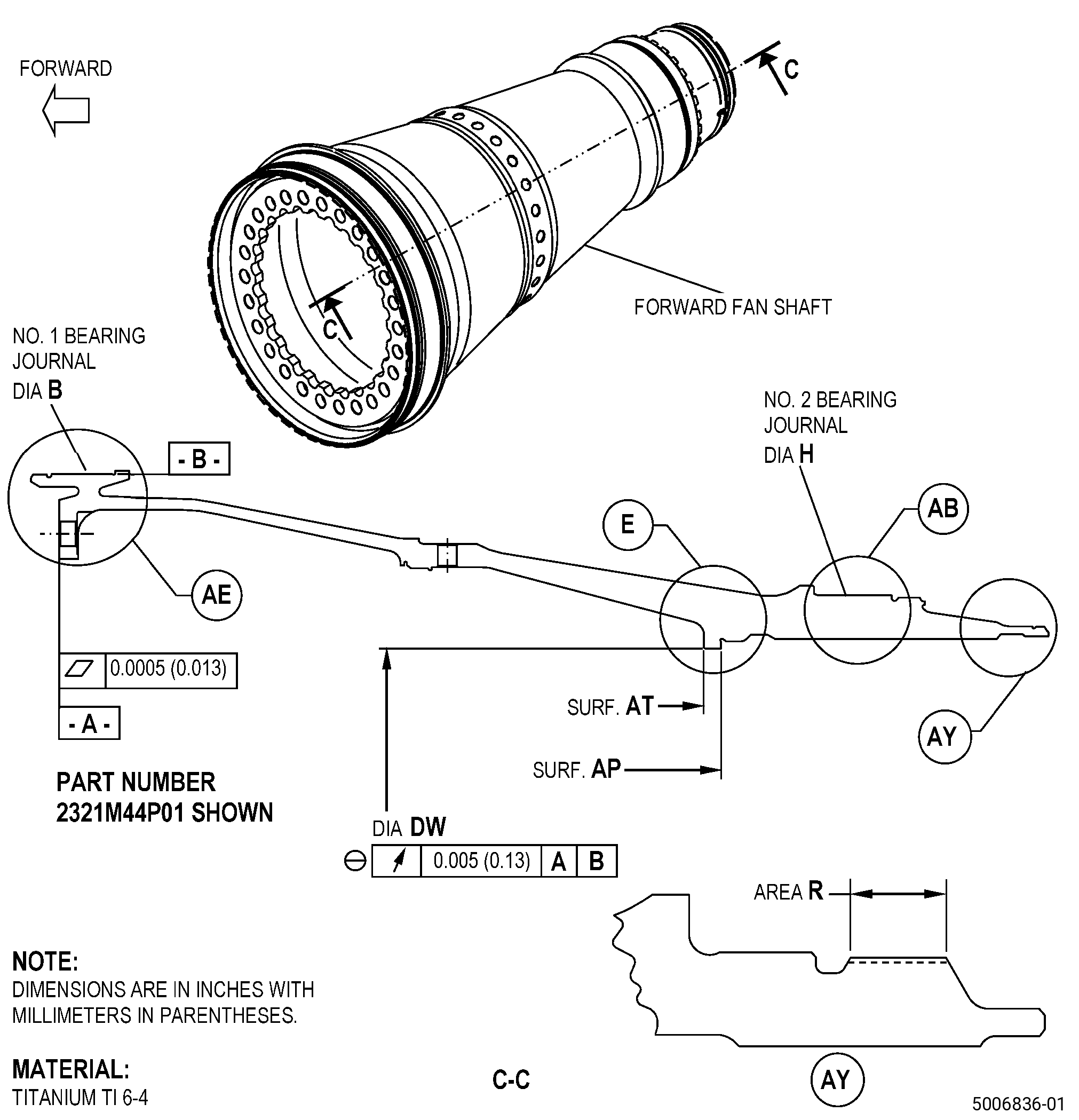
| FORWARD FAN SHAFT - REPAIR - THERMAL SPRAY REPAIR OF THE COUPLING NUT SEATING SURFACE (SURFACE AT) AND THE BEARING JOURNALS | ||
| GENX-1B CLEANING,INSPECTION,AND REPAIR MANUAL | Dated: 07/12/2023 | |
| CIR 72-24-40 , REPAIR 003 | ||
| FORWARD FAN SHAFT - REPAIR - THERMAL SPRAY REPAIR OF THE COUPLING NUT SEATING SURFACE (SURFACE AT) AND THE BEARING JOURNALS | ||
| * * * FOR ALL |
| TASK 72-24-40-300-803 |
| 1 . | Thermal Spray Repair of the Coupling Nut Seating Surface (Surface AT) and the Bearing Journals. |
| A. | This procedure gives instructions to repair the forward fan shaft (shaft) by replacing the damaged thermal spray coating on the coupling nut seating surface (surface AT) and the bearing journals (diameter B and diameter H). Refer to Figure 901. |
| B. | The following maximum repairable limits apply to this repair: |
| NOTE: |
|
| (4) | Visual Inspection. |
| (d) | Do an inspection of the No. 1 and No. 2 bearing journals for: |
| 1 | Wear on diameter B or diameter H: |
| Maximum repairable limit: |
|
| 2 | Nicks, dents, and scratches: |
| Maximum repairable limit: |
|
| 3 | Fretting: |
| Maximum repairable limit: |
|
| (i) | Do an inspection of the shaft coupling nut seating surface (surface AT) as follows. Refer to Figure 801. |
| 1 | Nicks, dents, scratches, and fretting: |
| Maximum repairable limit: |
|
| (5) | Dimensional Inspection. |
| (a) | Do an inspection of the shaft for: |
| 2 | No. 1 bearing journal (diameter B measured only on area JB): |
| Minimum repairable limit: |
|
| 3 | No. 2 bearing journal (diameter H measured only on area JH): |
| Minimum repairable limit: |
|
| C. | The subsequent table gives a list of the part numbers that are applicable to this procedure. All part numbers are applicable to all paragraphs unless specified differently. |
|
|||||||||||||||||||||||
| D. | Proprietary/Complex Process Statement. |
| (1) | None. |
| 2 . | Tools, Equipment, and Materials. |
| NOTE: |
|
| A. | Tools and Equipment. |
| (1) | Special Tools. None. |
| (2) | Standard Tools and Equipment. None. |
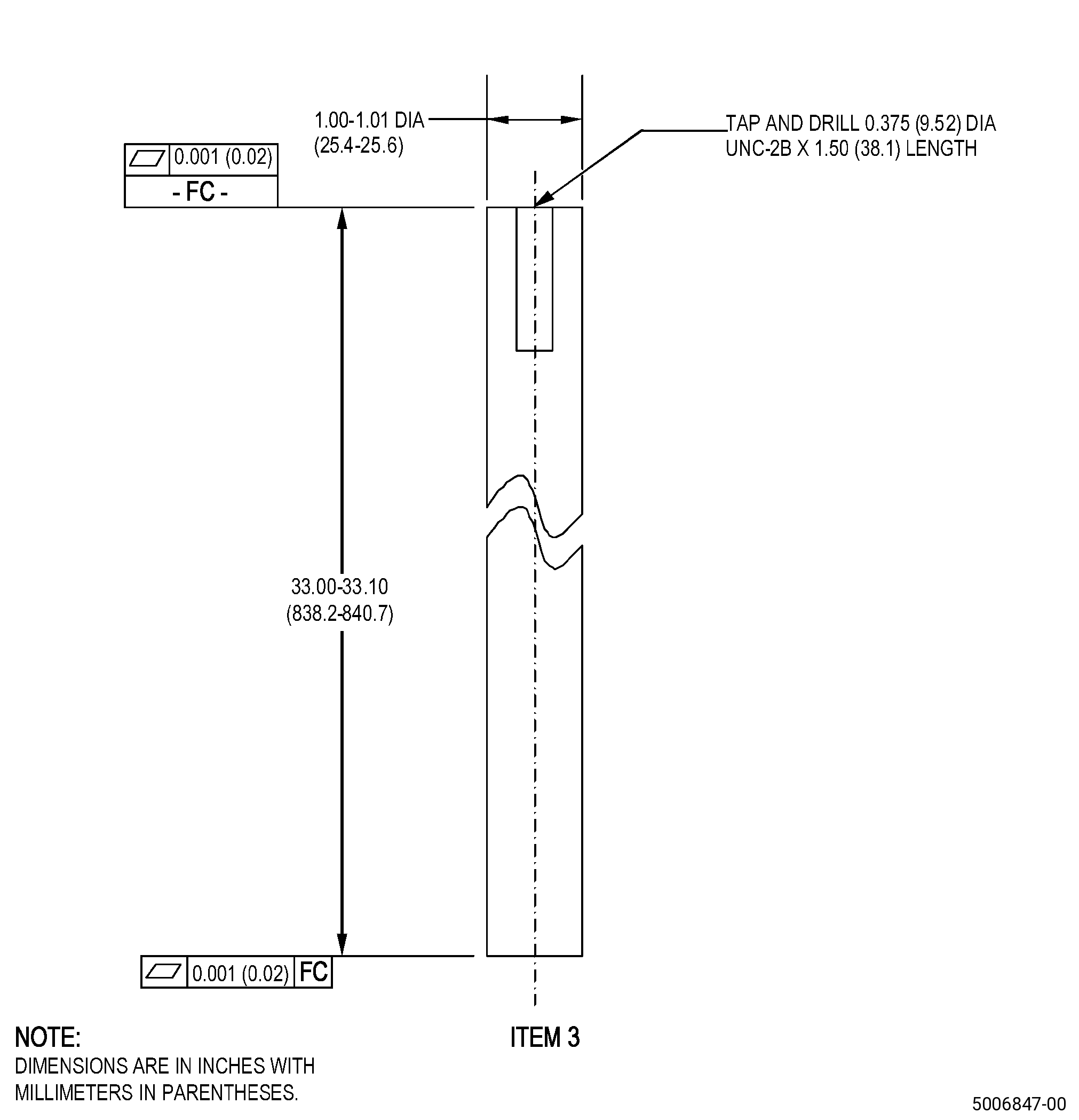
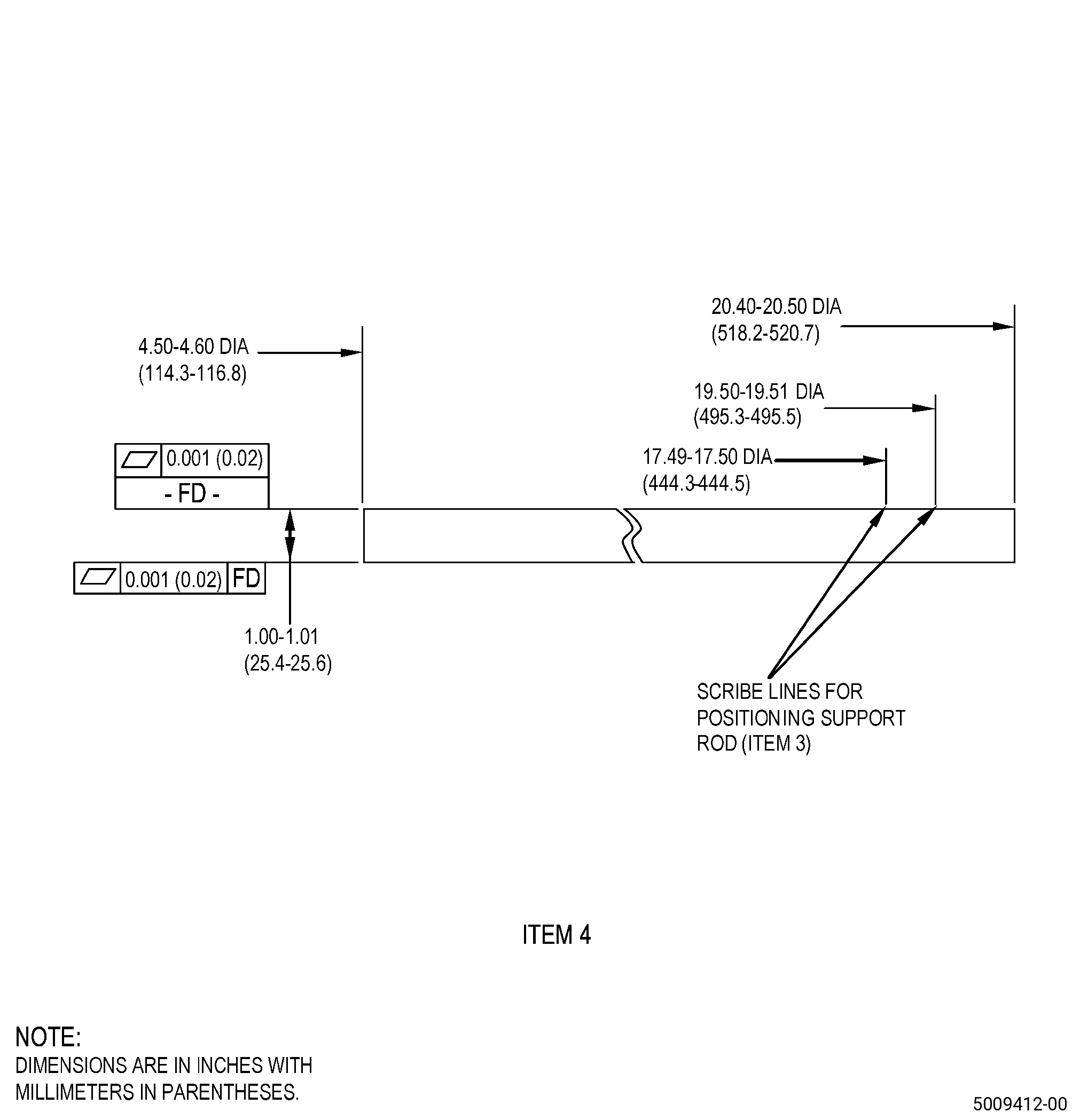
| (3) | Locally Manufactured Tools. |
|
| B. | Consumable Materials. |
| C. | Referenced Procedures. |
|
| D. | Expendable Parts. None. |
| E. | SPD Information. |
| (1) | Spares Supplied. None. |
| (2) | Protected Spares. None. |
| (3) | Locally Manufactured Spares. None. |
| F. | Special Solutions. None. |
| G. | Test Specimens. |
|
| 3 . | Dimensional Information. |
| Subtask 72-24-40-220-085 |
| A. | Refer to Figure 901 and Figure 902 for specified dimensions and locations. |
| NOTE: |
|
| NOTE: |
|
| 4 . | Setup Information. |
| Subtask 72-24-40-350-005 |
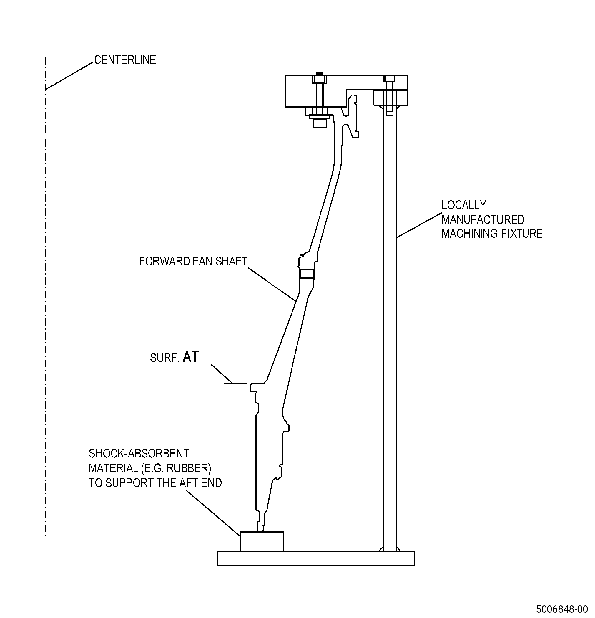
| A. | Alternative Procedure Available. Set-up the shaft to machine surface AT. Refer to Figure 904 and as follows: |
| Subtask 72-24-40-930-001 |
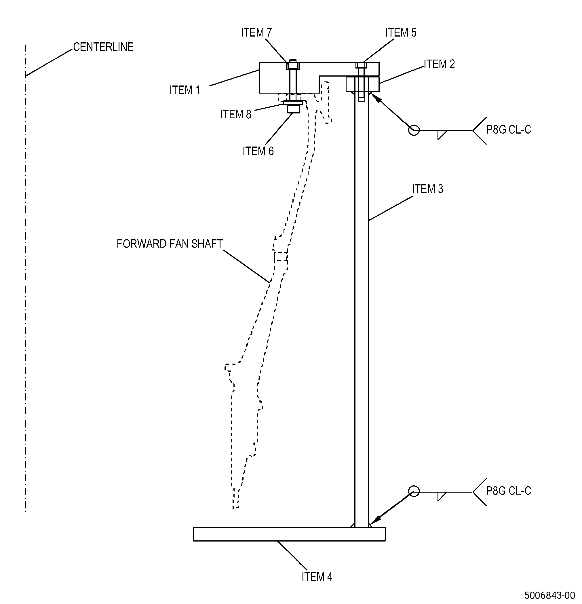
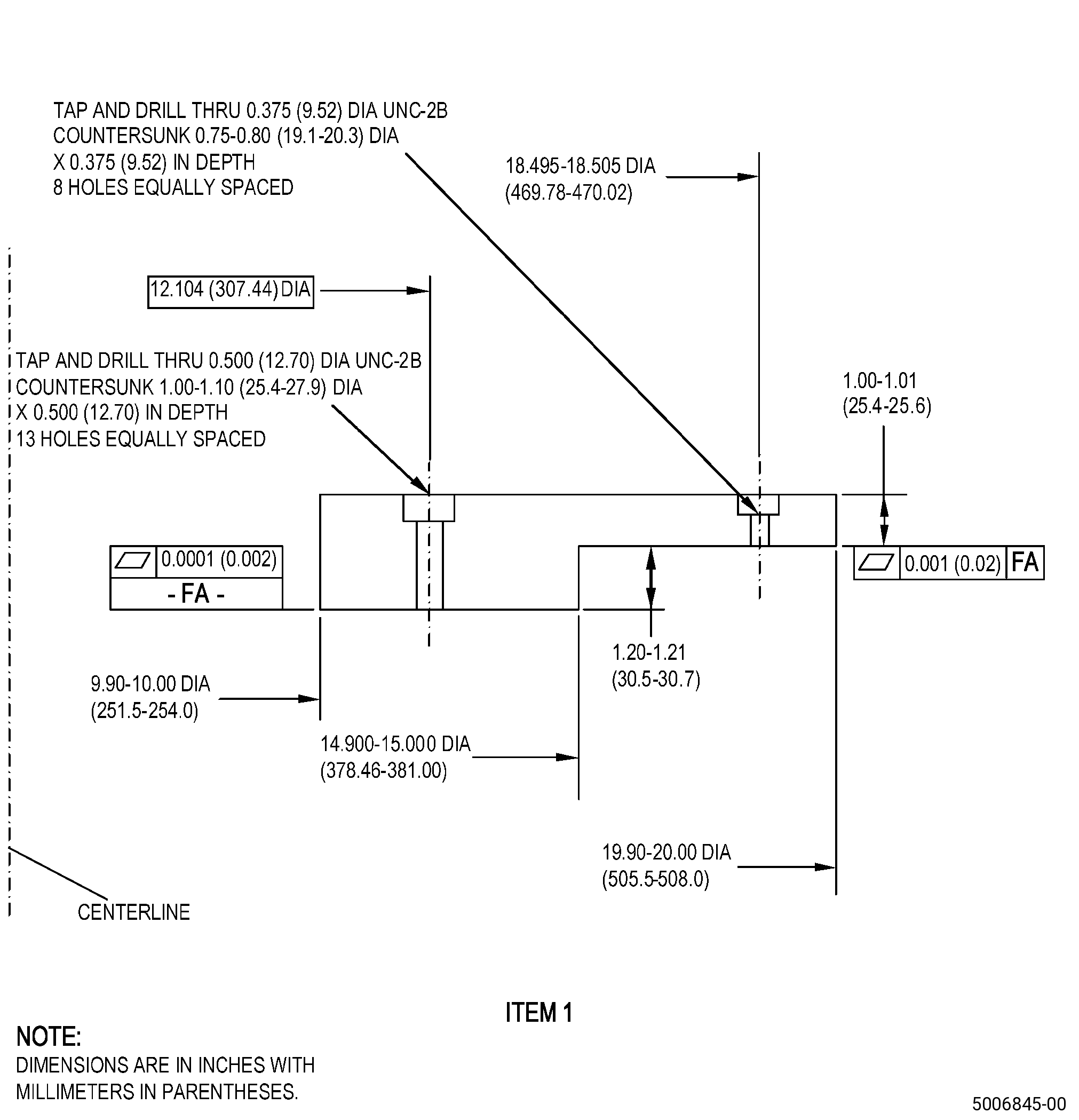
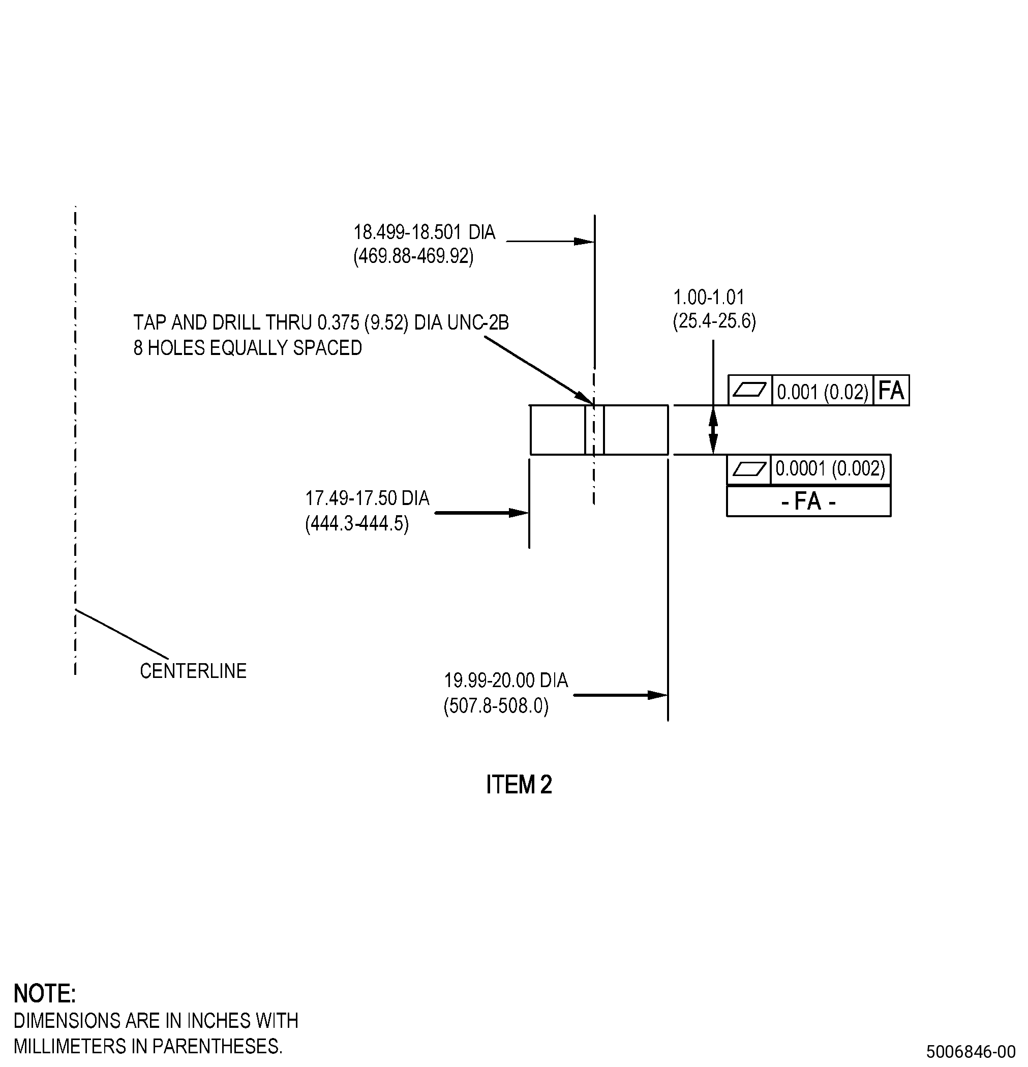
| (1) | If necessary, make the machining fixture. Refer to Figure 903. |
| Subtask 72-24-40-350-010 |
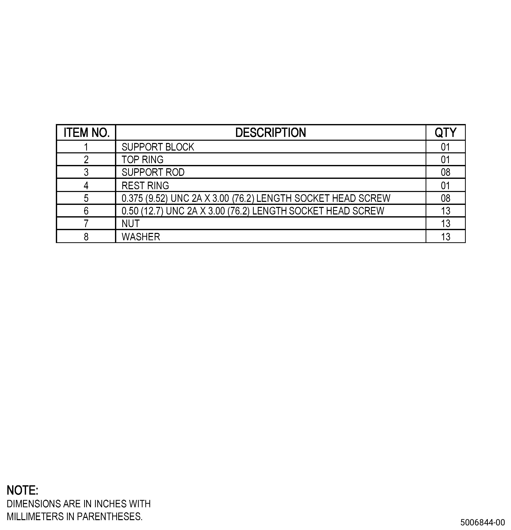
| (2) | Put the shaft forward end down onto the support block (item 1). |
| (3) | Install the shaft onto the support block (item 1) with socket head screws (item 6), washers (item 8), and nuts (item 7). |
| (4) | Make sure that the clearance between surface FA of the support block (item 1) and surface A of the shaft is a maximum of 0.001 inch (0.02 mm) FIR. |
| (5) | Install the machining fixture (top ring (item 2), support rods (item 3), and rest ring (item 4)) onto the machining table. |
| WARNING: |
|
| (6) | Lift the shaft and support block (item 1) with a hoist and turn the assembled shaft and support block (item 1) until the aft end of the shaft points down. |
| (7) | Install the assembled shaft and support block (item 1) onto the machining fixture (top ring (item 2), support rods (item 3), rest ring (item 4)) with eight socket head screws (item 5). |
| (8) | If necessary, use a shock absorbent material, for example, use a rubber to hold the aft end of the shaft to decrease the load on the machining fixture. Make sure that you use material that will not cause damage to the spline teeth or threads. |
| Subtask 72-24-40-350-016 |
| A.A. | Alternative Procedure. Set-up the shaft to machine surface AT. Refer to Figure 901 and as follows: |
| (1) | With surface A restrained and surface AP flatness to 0.0005 inch (0.013) the runout of diameter DW must be 0.005 inch (0.13 mm) or less. |
| Subtask 72-24-40-350-009 |
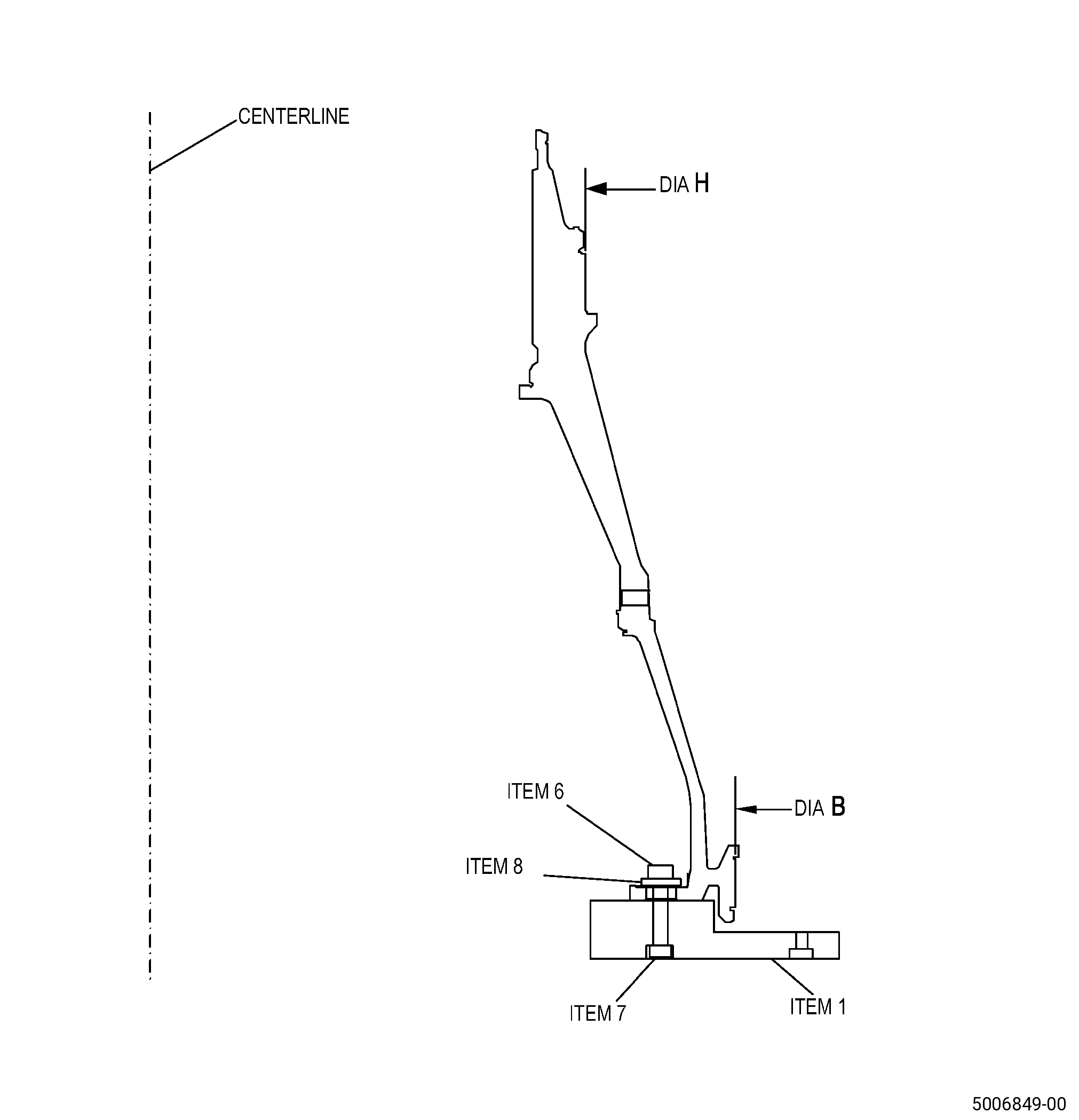
| B. | Set-up the shaft to machine diameter B and diameter H. Refer to Figure 905 and as follows: |
| (1) | Install the support block (item 1) onto the machining table. |
| (2) | Put the shaft forward end down onto the support block (item 1). |
| (3) | Install the shaft onto the support block (item 1) with socket head screws (item 6), washers (item 8), and nuts (item 7). |
| (4) | Make sure that the clearance between surface FA of the support block (item 1) and surface A of the shaft is a maximum of 0.001 inch (0.02 mm) FIR. |
| 5 . | Procedure. |
| Subtask 72-24-40-160-006 |
| A. | If necessary, clean the shaft. Refer to TASK 72-24-40-100-801 (72-24-40, CLEANING 001). |
| Subtask 72-24-40-220-086 |
| B. | Deleted. |
| Subtask 72-24-40-330-001 |
| C. | Alternative Procedure Available. Remove the thermal spray coating from the shaft repair areas. Refer to TASK 70-23-00-100-001 (STRIPPING PROCEDURES), TASK 70-23-09-100-002 (STRIPPING TUNGSTEN CARBIDE THERMAL SPRAYED COATING), Figure 901, Figure 902, and as follows: |
| (1) | Use Method 2 only. |
| (2) | Apply C10-012 masking tape to all the surfaces of the shaft where you will not remove thermal spray coating. |
| Subtask 72-24-40-320-001 |
| CAUTION: |
|
| C.A. | Alternative Procedure. Machine/grind the shaft repair areas to remove thermal spray coating and/or the remaining thermal spray coating. Refer to TASK 70-00-03-800-004 (MACHINING DATA), Figure 901, Figure 902, and as follows: |
| NOTE: |
|
| NOTE: |
|
| NOTE: |
|
| (1) | Machine/grind surface AT to remove the thermal spray coating from the shaft as follows: |
| (a) | Set-up the shaft to machine surface AT. Refer to Subtask 72-24-40-350-005 (paragraph 4.A.). |
| (b) | If you find overspray coating in the area DJ, machine to fully remove the overspray coating to a maximum diameter AD and to a maximum axial depth of 0.005 inch (0.12 mm). |
| Subtask 72-24-40-220-092 |
| (c) | Do a visual inspection of the shaft to make sure that you removed all the thermal spray coating. |
| NOTE: |
|
| Subtask 72-24-40-320-003 |
| (2) | Machine/grind area JB and area JH to remove the thermal spray coating from the shaft as follows: |
| (a) | Set-up the shaft to machine diameter B and diameter H. Refer to Subtask 72-24-40-350-009 (paragraph 4.B.). |
| Subtask 72-24-40-220-093 |
| (b) | Do a visual inspection of the shaft to make sure that you removed all the thermal spray coating. |
| NOTE: |
|
| Subtask 72-24-40-350-007 |
| D. | Blend the machined areas to remove all sharp edges from the shaft. Refer to TASK 70-42-00-350-002 (BLENDING AND REMOVAL OF HIGH METAL PROCEDURES), Figure 902, and as follows: |
| (1) | Break edges to a radius of 0.005-0.015 inch (0.13-0.38 mm). |
| Subtask 72-24-40-220-087 |
| E. | Do a dimensional inspection of the shaft repair areas. Refer to Figure 902 and as follows: |
| (1) | Do a dimensional inspection of diameter B, diameter H, and dimension TP to make sure that they agree with the necessary in-process dimensions. |
| (2) | If you machined diameter AD to remove overspray coating, do a dimensional inspection to make sure that it agrees with the maximum finish diameter AD and to a maximum axial depth of 0.005 inch (0.12 mm). |
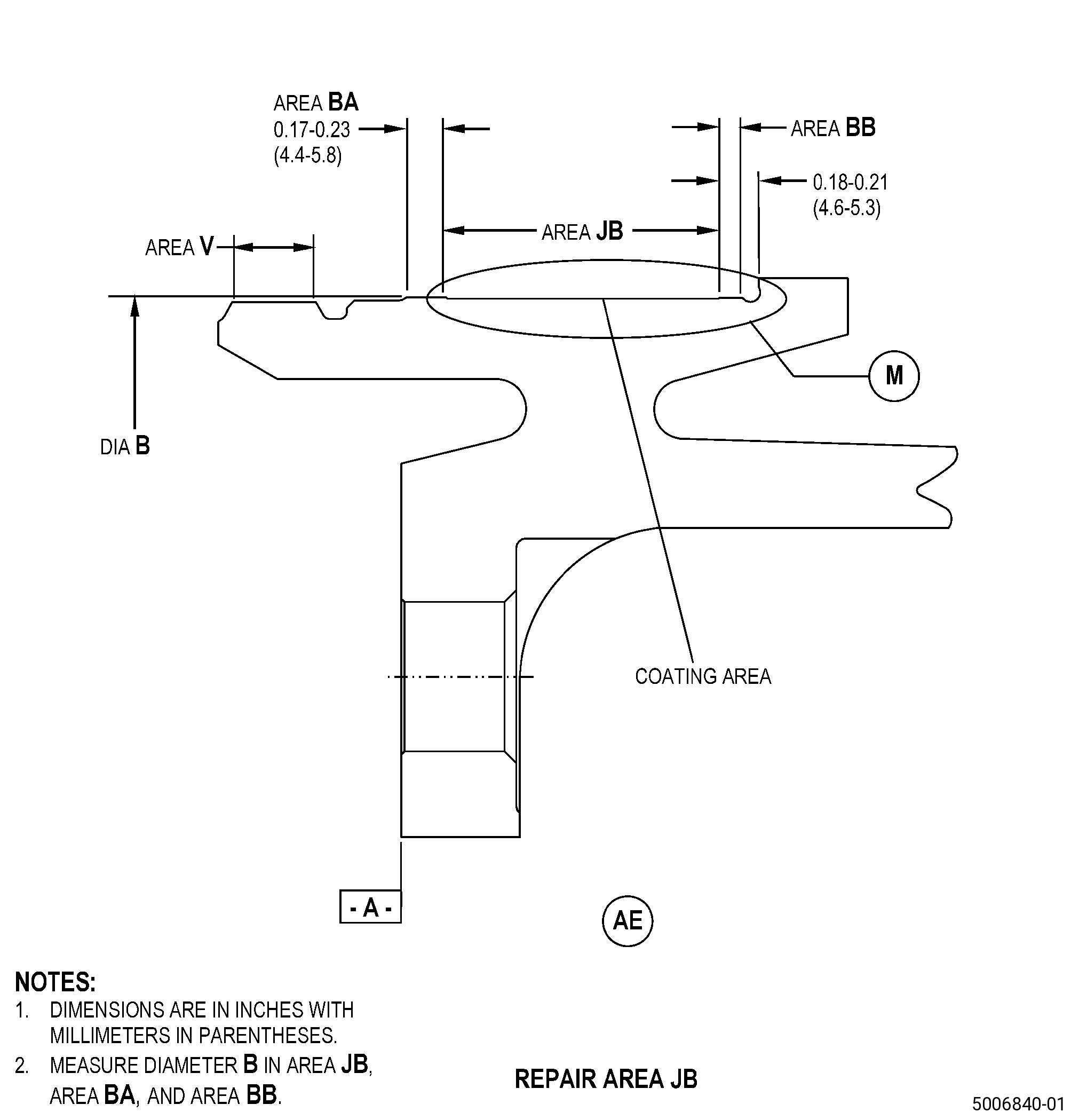
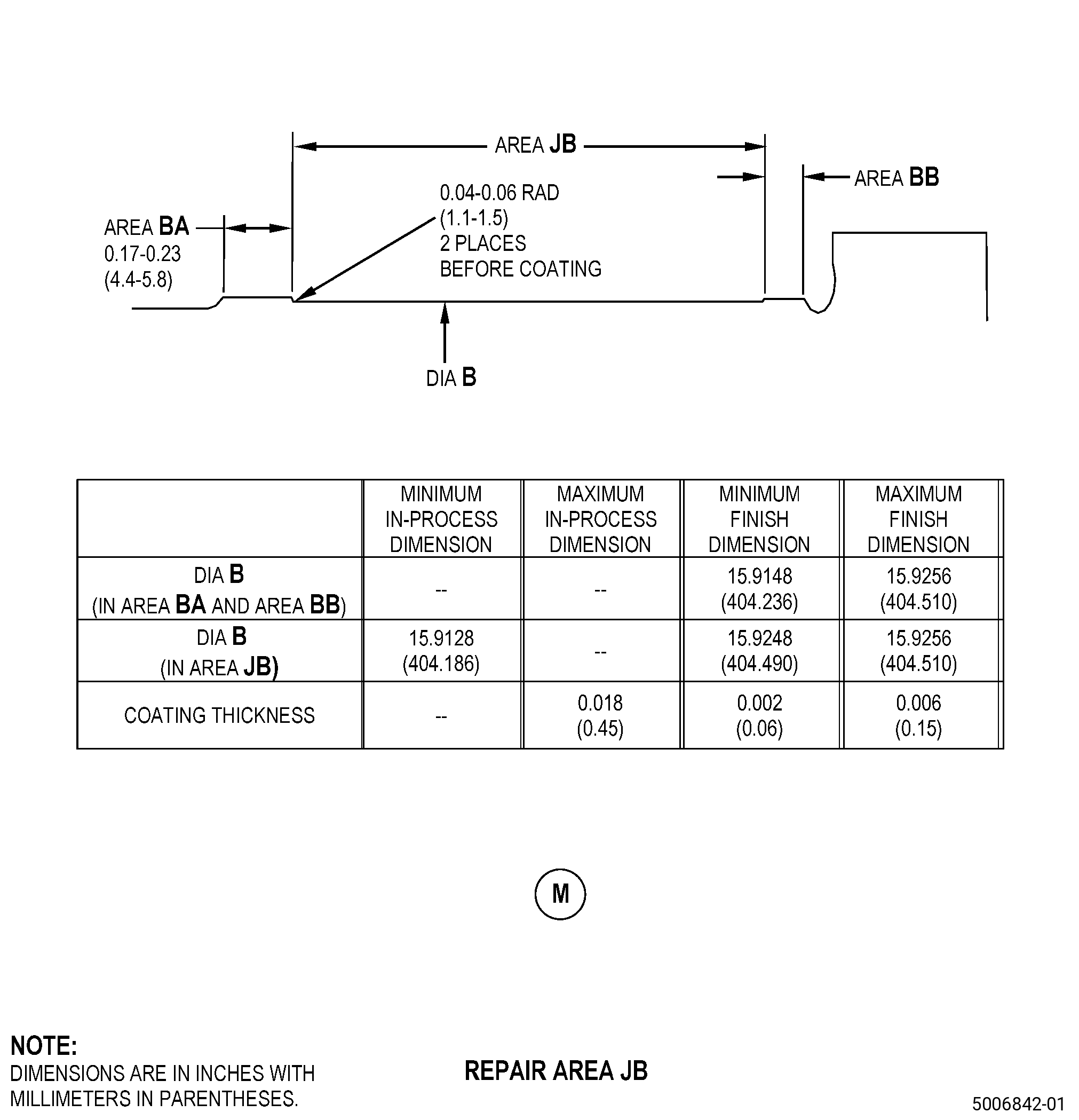
| (3) | Record the actual reading of diameter B at area BA, area BB, and area JB. You must use these values to find the maximum permitted mismatch at final machining. |
| Subtask 72-24-40-160-007 |
| F. | If necessary, clean the shaft. Refer to TASK 70-21-00-110-051 (CHEMICAL CLEANING) and TASK 70-21-03-160-001 (CLEANING METHOD NO. 3 - STEAM CLEANING). |
| Subtask 72-24-40-110-009 |
| G. | If you use machining to remove thermal spray coating from the shaft, etch the shaft repair areas. Refer to TASK 70-24-00-110-033 (ETCHING PROCEDURES FOR FLUORESCENT-PENETRANT INSPECTION), TASK 70-24-01-110-034 (SWAB ETCHING PROCEDURE), and as follows: |
| (1) | Use Class B etchant. |
| Subtask 72-24-40-230-003 |
| H. | Do an inspection of the shaft repair areas. Refer to TASK 70-32-00-200-002 (INDIRECT INSPECTION METHODS), TASK 70-32-03-230-002 (SPOT-FLUORESCENT-PENETRANT INSPECTION), and as follows: |
| (1) | Use Class G penetrant. |
| (2) | Linear indications that are 0.015 inch (0.38 mm) or smaller are permitted. |
| NOTE: |
|
| Subtask 72-24-40-220-088 |
| I. | Before you apply the thermal spray coating, do a visual inspection of the shaft repair areas. Refer to TASK 72-24-40-200-801 (72-24-40, INSPECTION 001). |
| Subtask 72-24-40-380-003 |
| J. | Peen the repair areas of diameter B, diameter H, surface AT, and diameter AD of the shaft. Refer to TASK 70-47-01-380-016 (SHOTPEENING), Figure 902, and as follows: |
| NOTE: |
|
| (1) | Apply C10-021 plastic tape to area N, area R, area V, and all adjacent surfaces that you will not peen. |
| (2) | Use C04-271 S110 cast steel shots. |
| (3) | Peen to an intensity of 0.006-0.012N. |
| (4) | Overspray is permitted, but not in area N, area R, and area V. |
| (5) | Coverage must be a minimum of 100 percent. |
| (6) | Use C10-205 Almen N test strips to do an intensity verification at the repair areas. |
| Subtask 72-24-40-340-001 |
| WARNING: |
|
| K. | Thermal-spray the repair area JB, area JH, surface AT of the shaft and the test specimens. Refer to TASK 70-49-00-340-001 (THERMAL SPRAYING), TASK 70-49-37-340-036 (TUNGSTEN CARBIDE/17% COBALT WEAR COATING APPLIED BY HIGH VELOCITY OXY-FUEL (HVOF) PROCESS), Figure 901, Figure 902, and as follows: |
| (1) | Apply C10-012 masking tape to area N, area V, and all adjacent surfaces that you will not thermal-spray. |
| (2) | Grit-blast the shaft to prepare the surfaces for thermal spraying. Use the parameters in TASK 70-49-00-340-001 (THERMAL SPRAYING) for titanium parts and as follows: |
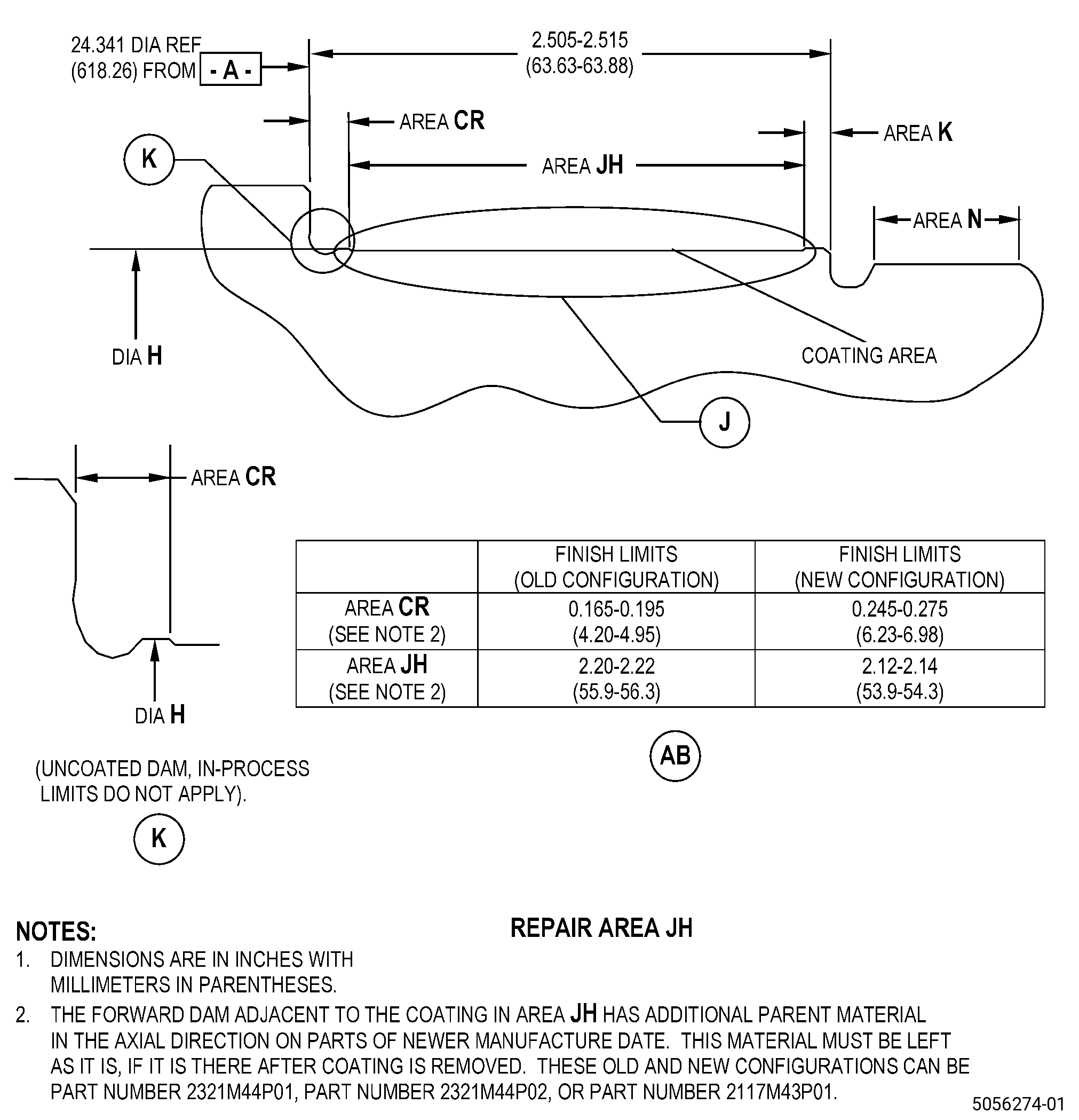
| (a) | Overspray is permitted in area BA, area BB, area CR, and area K. |
| (3) | Thermal-spray coating thickness must be 0.002-0.006 inch (0.06-0.15 mm) after final machining. Make sure that you apply the thermal spray coating to a maximum as-sprayed thickness of 0.018 inch (0.45 mm). |
| (4) | Overspray coating is permitted in area DJ on the flat surface only and as follows: |
| (a) | Overspray coating is not permitted in the pocket radius. |
| (5) | Overspray is permitted in area BA, area BB, area CR, and area K, but you must remove it during the final machining. |
| NOTE: |
|
| (6) | Do all the quality assurance testing specified in TASK 70-49-37-340-036 (TUNGSTEN CARBIDE/17% COBALT WEAR COATING APPLIED BY HIGH VELOCITY OXY-FUEL (HVOF) PROCESS). |
| Subtask 72-24-40-320-002 |
| L. | Machine/grind the shaft repair areas to the finish dimensions. Refer to TASK 70-00-03-800-004 (MACHINING DATA), Figure 902, and as follows: |
| (1) | Machine/grind surface AT to the finish dimensions as follows: |
| (a) | Set-up the shaft to machine surface AT. Refer to Subtask 72-24-40-350-005 (paragraph 4.A.). |
| (b) | Overspray is not permitted into the pocket radius in the area DJ. |
| (c) | A maximum mismatch of 0.002 inch (0.05 mm) is permitted. |
| (2) | Machine/grind diameter B and diameter H to the finish dimensions as follows: |
| (a) | Set-up the shaft to machine diameter B and diameter H. Refer to Subtask 72-24-40-350-009 (paragraph 4.B.). |
| (b) | If it is necessary to remove the overspray coating from the No. 1 bearing journal (diameter B), it is permitted to remove a minimum quantity of parent material from the adjacent dams (area BA and area BB) to fully remove the overspray coating. |
| (c) | If it is necessary to remove the overspray coating from the No. 2 bearing journal (diameter H), you must make sure that diameter H at area CR, area K, and area JH agrees with finish dimensions. Mismatch between area JH and the adjacent dams (area CR and area K) is not permitted. |
| (d) | Make sure that there is a minimum radius of 0.010 inch (0.26 mm) at the thermal spray coating edge. |
| (3) | The surface finish after final grind must be 32 microinches (0.81 micrometers) or better. |
| Subtask 72-24-40-220-089 |
| M. | Do a dimensional inspection of the shaft repaired areas. Refer to Figure 902 and as follows: |
| (1) | Make sure that the thermal sprayed areas, the adjacent area BA, area BB, area CR, and area K agree with the finish dimensions. |
| Subtask 72-24-40-220-091 |
| (2) | Record the actual reading of diameter B at area BA and area BB again. If the dimensions measured at area BA and area BB after the final machining are smaller than the dimensions measured at area JB in Subtask 72-24-40-220-087 (paragraph 5.E.(3)), before you apply thermal spray coating, this shaft is not serviceable. |
| Subtask 72-24-40-220-090 |
| N. | Do an inspection of the thermal spray coating as follows: |
| (1) | Use a white light. |
| (2) | Linear indications, flaking, chipping, blistering, and separation of coating are not permitted. |
| NOTE: |
|
| (3) | A maximum of four missing coating areas are permitted at each thermal sprayed surface and as follows: |
| (a) | The missing coating can be a maximum of 0.03 inch (0.7 mm) in diameter with a maximum depth no more than the coating thickness. |
| (b) | There must be a minimum distance of 0.05 inch (1.3 mm) between adjacent missing coating areas. |
| (c) | Each missing coating area must have a smooth and rounded bottom. |
| (4) | Deleted. |
| Subtask 72-24-40-230-004 |
| O. | Do an inspection of the thermal spray coating. Refer to TASK 70-32-00-200-002 (INDIRECT INSPECTION METHODS), TASK 70-32-03-230-002 (SPOT-FLUORESCENT-PENETRANT INSPECTION), and as follows: |
| (1) | Use Class G penetrant. |
| (2) | Linear indications that are 0.015 inch (0.38 mm) or smaller are permitted. |
| NOTE: |
|
| Subtask 72-24-40-350-008 |
| CAUTION: |
|
| P. | Deleted. |
| Subtask 72-24-40-160-008 |
| Q. | Clean the shaft. Refer to TASK 70-21-00-110-051 (CHEMICAL CLEANING) and TASK 70-21-03-160-001 (CLEANING METHOD NO. 3 - STEAM CLEANING). |
| Subtask 72-24-40-350-017 |
| CAUTION: |
|
| R. | Apply the dry film lubricant to the shaft. Refer to TASK 72-24-40-300-801 (72-24-40, REPAIR 001). |
| Subtask 72-24-40-160-009 |
| CAUTION: |
|
| S. | Do a cleanliness inspection to the shaft. Refer to TASK 70-22-00-100-001 (SPECIAL CLEANING PRECAUTIONS), TASK 70-22-80-160-801 (SPECIAL CLEANING PROCEDURE NO. 80 - CLEANLINESS INSPECTION), and as follows: |
| (1) | Use Class C cleanliness. |