| GENX-1B CLEANING,INSPECTION,AND REPAIR MANUAL | Dated: 08/20/2024 | |
| CIR 72-30-99 , INSPECTION 001 | ||
| HIGH PRESSURE COMPRESSOR HARDWARE - INSPECTION | ||
| GENX-1B CLEANING,INSPECTION,AND REPAIR MANUAL | Dated: 08/20/2024 | |
| CIR 72-30-99 , INSPECTION 001 | ||
| HIGH PRESSURE COMPRESSOR HARDWARE - INSPECTION | ||
| * * * FOR ALL |
| TASK 72-30-99-200-801 |
| 1 . | General. |
| A. | This procedure gives instructions to do an inspection of the high pressure compressor (HPC) hardware that follows: |
| Alignment pin: |
| • |
|
| • |
|
| Bolt spacer (spacer): |
| • |
|
| • |
|
| • |
|
| Compressor stator spline seals (spline seals) stage 5 thru stage 9: |
| • |
|
| • |
|
| • |
|
| • |
|
| • |
|
| Double hex head bolts (hex bolts): |
| • |
|
| • |
|
| • |
|
| • |
|
| • |
|
| • |
|
| • |
|
| • |
|
| Double hex head shear bolts (shear bolts): |
| • |
|
| • |
|
| • |
|
| • |
|
| • |
|
| • |
|
| • |
|
| • |
|
| • |
|
| • |
|
| • |
|
| • |
|
| • |
|
| • |
|
| • |
|
| • |
|
| Free running nuts: |
| • |
|
| • |
|
| • |
|
| • |
|
| • |
|
| • |
|
| • |
|
| • |
|
| IGV thru stage 4 clevises (clevises): |
| • |
|
| • |
|
| • |
|
| • |
|
| • |
|
| • |
|
| • |
|
| • |
|
| IGV thru stage 4 turnbuckle bodies (turnbuckle bodies): |
| • |
|
| • |
|
| • |
|
| • |
|
| • |
|
| • |
|
| Machine Bolt: |
| • |
|
| Nuts: |
| • |
|
| • |
|
| • |
|
| • |
|
| Self-locking nuts: |
| • |
|
| • |
|
| • |
|
| • |
|
| • |
|
| • |
|
| • |
|
| • |
|
| • |
|
| • |
|
| • |
|
| • |
|
| • |
|
| • |
|
| • |
|
| • |
|
| • |
|
| • |
|
| Slabbed head bolts (slab bolts): |
| • |
|
| • |
|
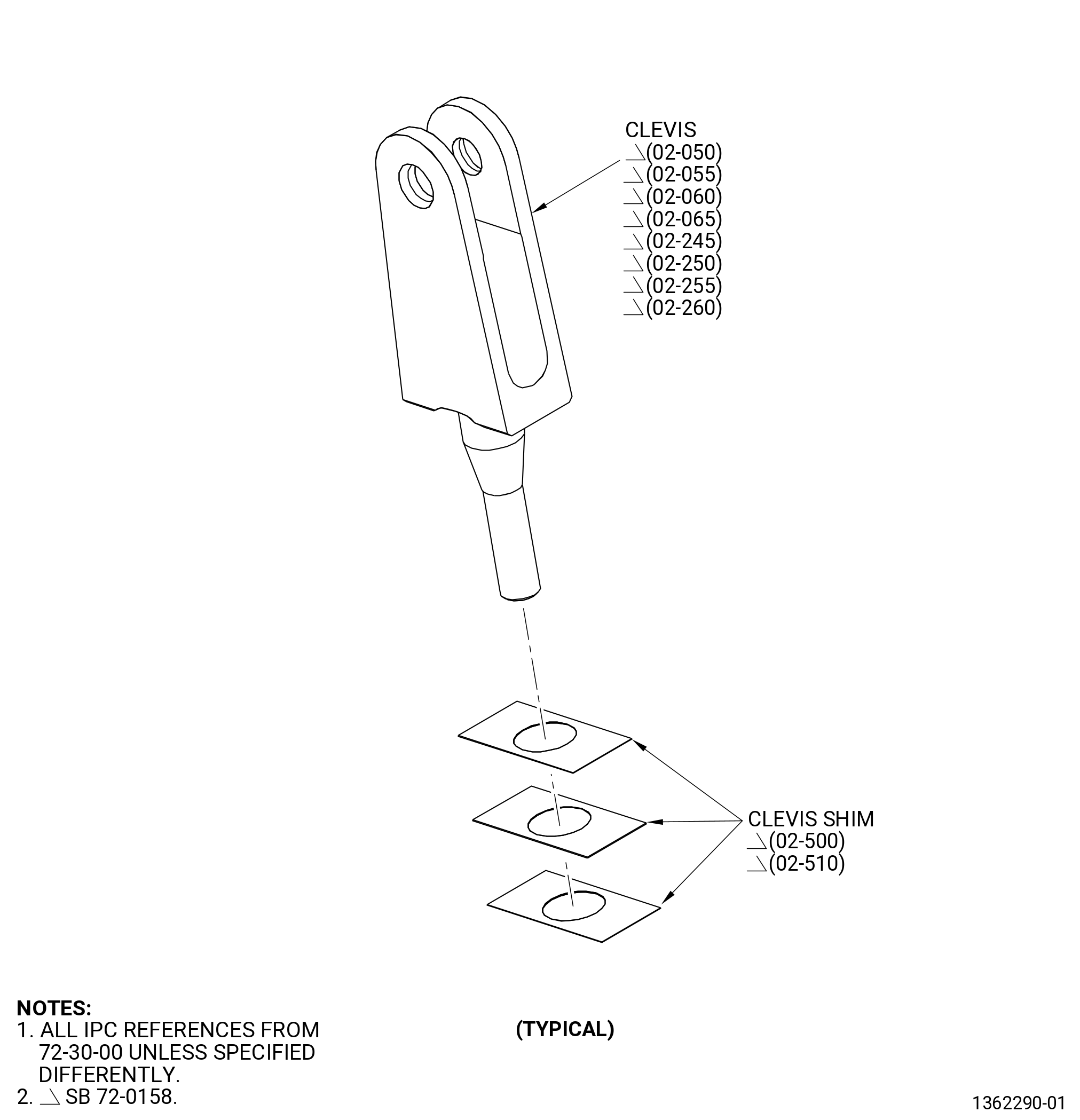
| Torque shaft clevis shims (clevis shims): |
| • |
|
| • |
|
| • |
|
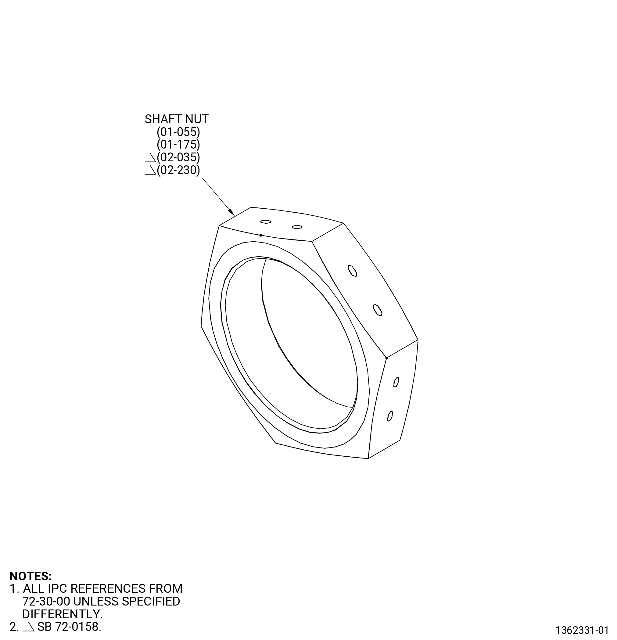
| Torque shaft nut (shaft nut): |
| • |
|
| • |
|
| • |
|
| • |
|
| Turnbuckle rod end assemblies (rod end assemblies): |
| • |
|
| • |
|
| • |
|
| • |
|
| • |
|
| • |
|
| • |
|
| • |
|
| • |
|
| • |
|
| • |
|
| • |
|
| 2 . | Tools, Equipment, and Materials. |
| NOTE: |
|
| A. | Tools and Equipment. |
| (1) | Special Tools. None. |
| (2) | Standard Tools and Equipment. None. |
| (3) | Locally Manufactured Tools. None. |
| B. | Consumable Materials. None. |
| C. | Referenced Procedures. |
| D. | Expendable Parts. None. |
| 3 . | Specific Inspection Procedure. |
| Subtask 72-30-99-230-001 |
| A. | Alternative Procedure Available. Do a Class A fluorescent penetrant inspection of the HPC hardware (this does not include the turnbuckle bodies). Refer to TASK 70-32-02-230-001 (FLUORESCENT PENETRANT INSPECTION). |
| (1) | Cracks are not permitted. |
| Subtask 72-30-99-230-002 |
| A.A. | Alternative Procedure. Do a spot-fluorescent-penetrant inspection of the HPC hardware (this does not include the turnbuckle bodies). Refer to TASK 70-32-03-230-002 (SPOT-FLUORESCENT-PENETRANT INSPECTION). |
| (1) | Cracks are not permitted. |
| Subtask 72-30-99-230-003 |
| B. | Do a class D fluorescent penetrant inspection of the external areas of the turnbuckle bodies. Refer to TASK 70-32-02-230-001 (FLUORESCENT PENETRANT INSPECTION). |
| (1) | Cracks are not permitted. |
| 4 . | Visual Inspection. |
| Subtask 72-30-99-220-004 |
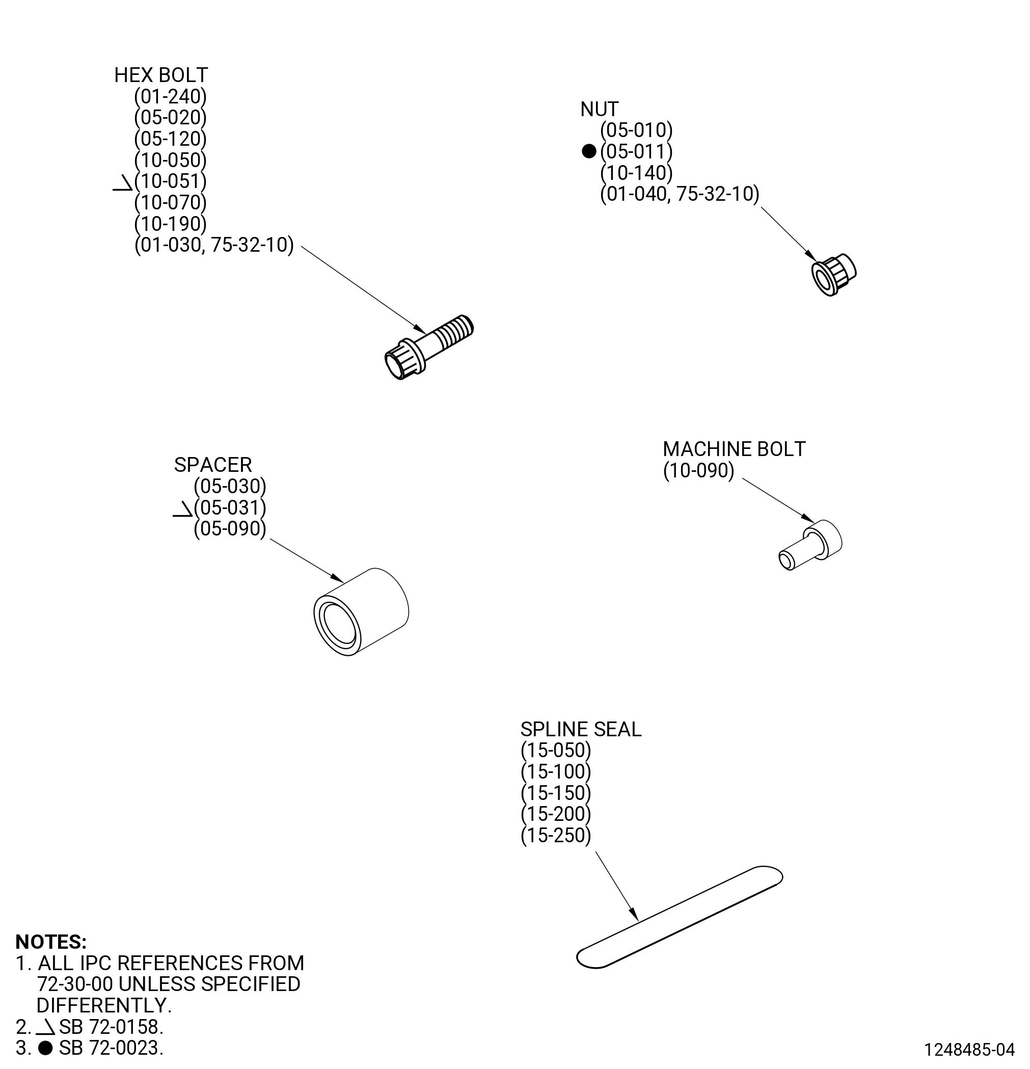
| A. | Do an inspection of each spline seal for. Refer to Figure 801. |
| (1) | Cracks: |
| Maximum serviceable limit: |
|
| Repair method: |
|
| Subtask 72-30-99-220-005 |
| (2) | Fretting, galling, and wear: |
| Maximum serviceable limit: |
|
| Repair method: |
|
| Subtask 72-30-99-220-006 |
| (3) | Distortion: |
| Maximum serviceable limit: |
|
| Repair method: |
|
| Subtask 72-30-99-220-007 |
| (4) | Wear and missing material on the ends: |
| Maximum serviceable limit: |
|
| Repair method: |
|
|
|
|
|
| Subtask 72-30-99-220-008 |
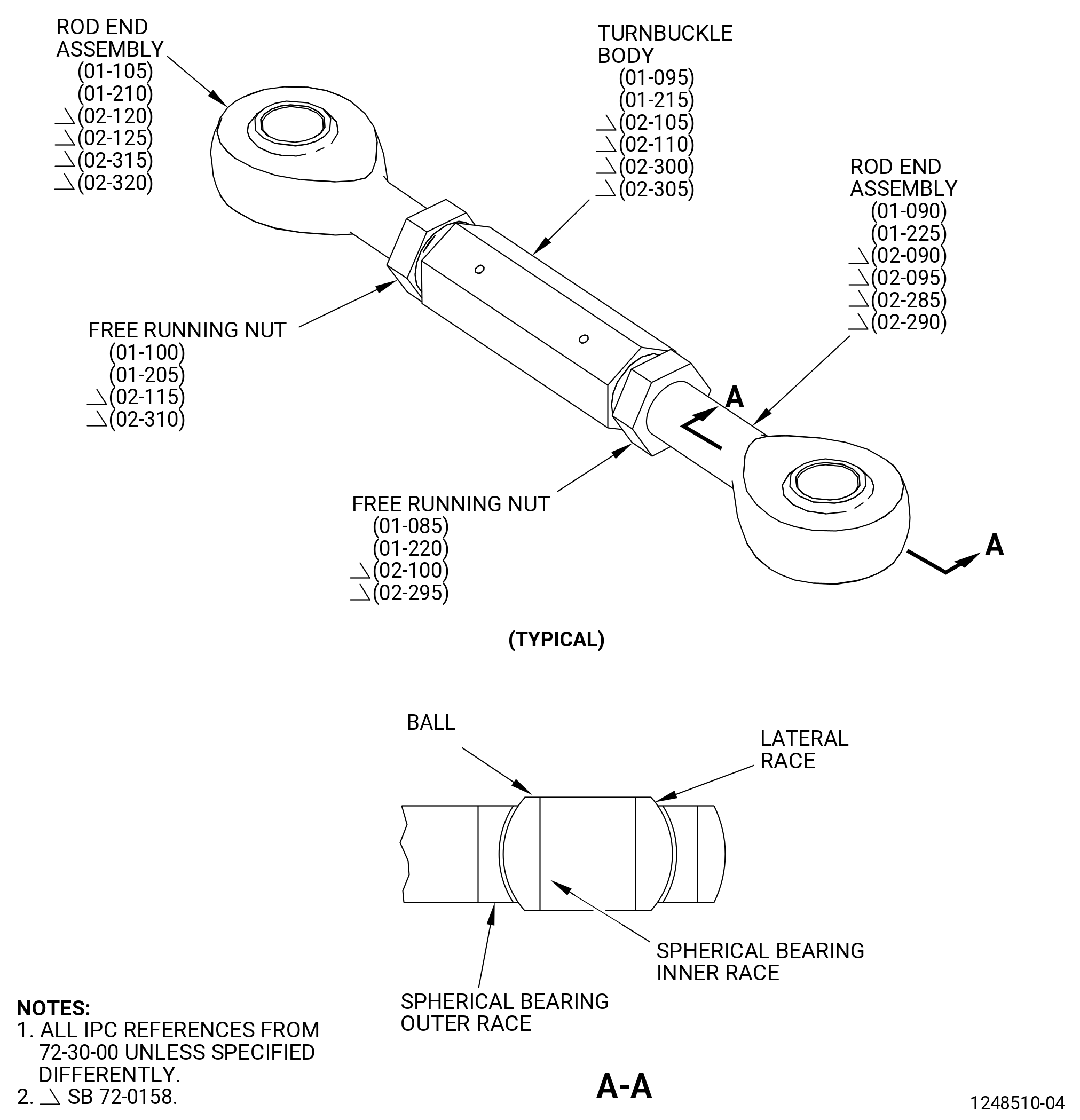
| B. | Do an inspection of all areas of each turnbuckle or fixed link for. Refer to Figure 803. |
| (1) | Cracks: |
| Maximum serviceable limit: |
|
| Repair method: |
|
| Subtask 72-30-99-220-009 |
| * * * PRE SB 72-0483 |
| (2) | Looseness of either nut: |
| Maximum serviceable limit: |
|
| Maximum repairable limit: |
|
| Repair method: |
|
| * * * END PRE SB 72-0483 |
| Subtask 72-30-99-220-011 |
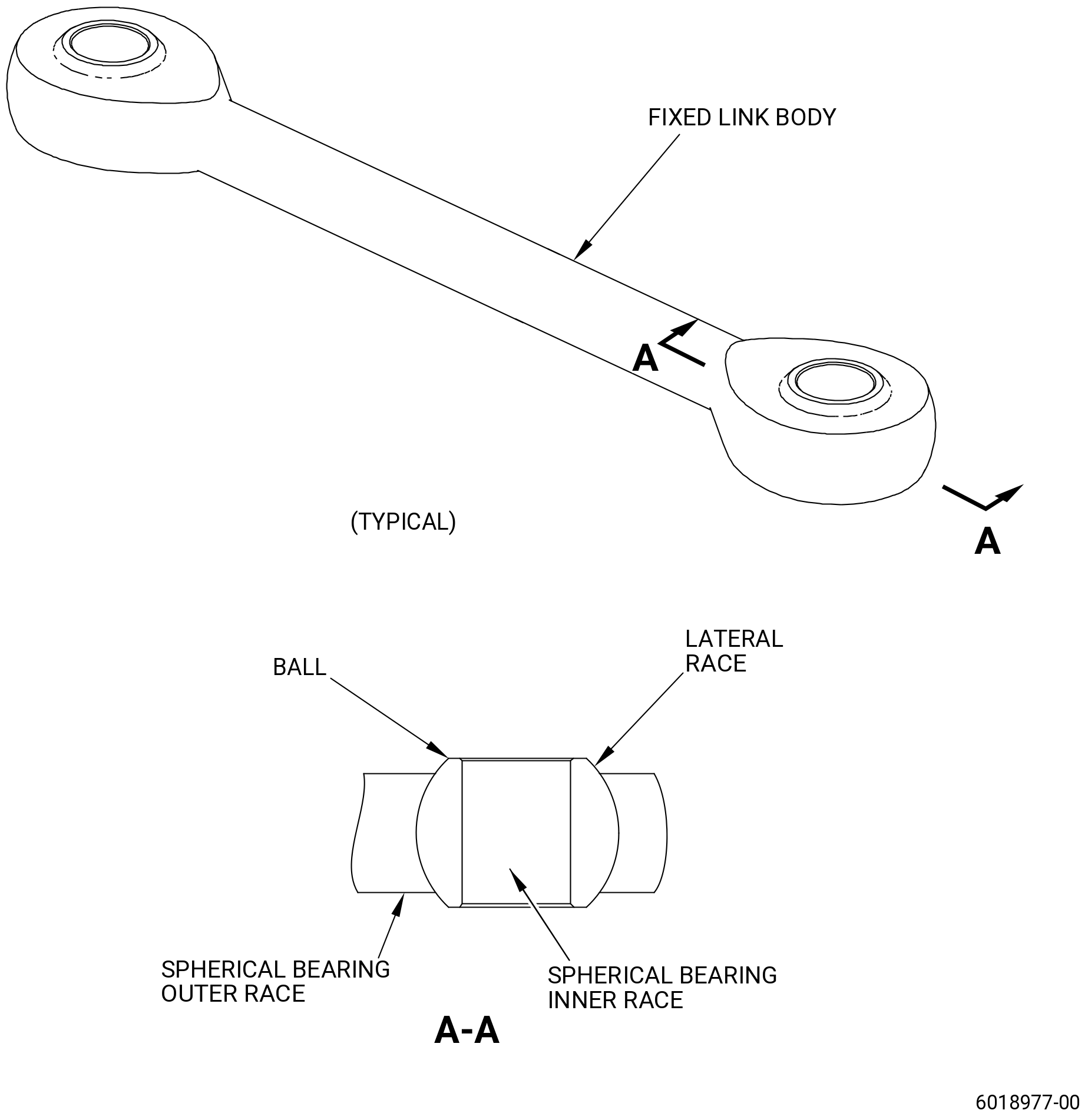
| C. | Do an inspection of the spherical bearings of each turnbuckle or fixed link for. Refer to Figure 803. |
| (1) | Circumferential movement of ball: |
| Maximum serviceable limit: |
|
| Repair method: |
|
| Subtask 72-30-99-220-012 |
| (2) | A ball that will not turn side-to-side (pivot) in the spherical bearing outer race: |
| Maximum serviceable limit: |
|
| Repair method: |
|
| Subtask 72-30-99-220-013 |
| (3) | Radial clearance of the balls in the spherical bearings in the outer race: |
| Maximum serviceable limit: |
|
| Repair method: |
|
| Subtask 72-30-99-220-014 |
| (4) | Nicks, dents, scratches, and galling on each spherical bearing inner race: |
| Maximum serviceable limit: |
|
| Repair method: |
|
| Subtask 72-30-99-220-015 |
| (5) | Nicks, dents, scratches, and pits on the lateral faces of each spherical bearing outer race: |
| Maximum serviceable limit: |
|
| Repair method: |
|
| Subtask 72-30-99-220-016 |
| (6) | Axial looseness of each spherical bearing outer race in the rod ends: |
| Maximum serviceable limit: |
|
| Repair method: |
|
| Subtask 72-30-99-220-017 |
| (7) | Axial looseness of the ball in each spherical bearing outer race: |
| Maximum serviceable limit: |
|
| Repair method: |
|
| Subtask 72-30-99-220-018 |
| D. | Do an inspection of the rod end assemblies of each turnbuckle for. Refer to Figure 803. |
| (1) | Damage to the threads: |
| Maximum serviceable limit: |
|
| Maximum repairable limit: |
|
| Repair method: |
|
| Subtask 72-30-99-220-019 |
| (2) | Nicks, dents, scratches, and pits (this does not include the spherical bearing outer race): |
| Maximum serviceable limit: |
|
| Maximum repairable limit: |
|
| Repair method: |
|
| Subtask 72-30-99-220-045 |
| * * * SB 72-0483 |
| E. | Do an inspection of the fixed link body for. Refer to Figure 804. |
| (1) | Nicks, dents, scratches, and pits (this does not include the spherical bearing outer race): |
| Maximum serviceable limit: |
|
| Maximum repairable limit: |
|
| Repair method: |
|
| * * * END SB 72-0483 |
| Subtask 72-30-99-220-020 |
| * * * DELETED( ) |
| * * * DELETED( ) |
| F. | Do an inspection of the clevises for. Refer to Figure 805. |
| NOTE: |
|
| (1) | Nicks, dents, scratches on each clevis: |
| Maximum serviceable limit: |
|
| Maximum repairable limit: |
|
| Repair method: |
|
| Subtask 72-30-99-220-021 |
| (2) | Rub marks on the bolthead, turnbuckle, and nut mating surface: |
| Maximum serviceable limit: |
|
| Repair method: |
|
| Subtask 72-30-99-220-022 |
| (3) | Thread damage: |
| Maximum serviceable limit: |
|
| Maximum repairable limit: |
|
| Repair method: |
|
| Subtask 72-30-99-220-046 |
| (4) | Wear due to contact with turnbuckle rod end on inner surface of the shaft stage clevises (IGV through stage 4): |
| Maximum serviceable limit: |
|
| Repair method: |
|
| * * * DELETED |
| * * * DELETED |
| Subtask 72-30-99-220-023 |
| G. | Do an inspection of the shaft nut for. Refer to Figure 806. |
| (1) | Cracks: |
| Maximum serviceable limit: |
|
| Repair method: |
|
| Subtask 72-30-99-220-024 |
| (2) | Nicks, dents, and scores: |
| Maximum serviceable limit: |
|
| Repair method: |
|
| Subtask 72-30-99-220-027 |
| (3) | High metal in the safety wire holes: |
| Maximum serviceable limit: |
|
| Repair method: |
|
| Subtask 72-30-99-220-031 |
| H. | Do an inspection of the spacers for. Refer to Figure 801. |
| (1) | Cracks: |
| Maximum serviceable limit: |
|
| Repair method: |
|
| Subtask 72-30-99-220-032 |
| (2) | Fretting and galling: |
| Maximum serviceable limit: |
|
| Repair method: |
|
| Subtask 72-30-99-220-033 |
| (3) | Nicks, dents, and scratches: |
| Maximum serviceable limit: |
|
| Repair method: |
|
| Subtask 72-30-99-220-034 |
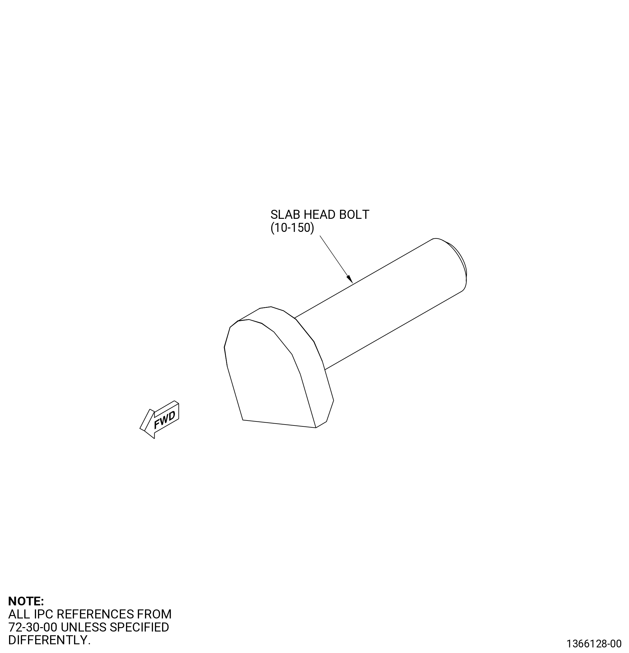
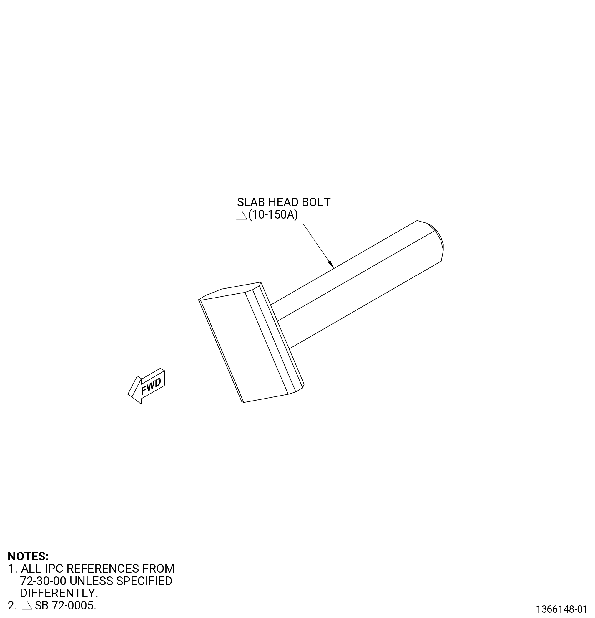
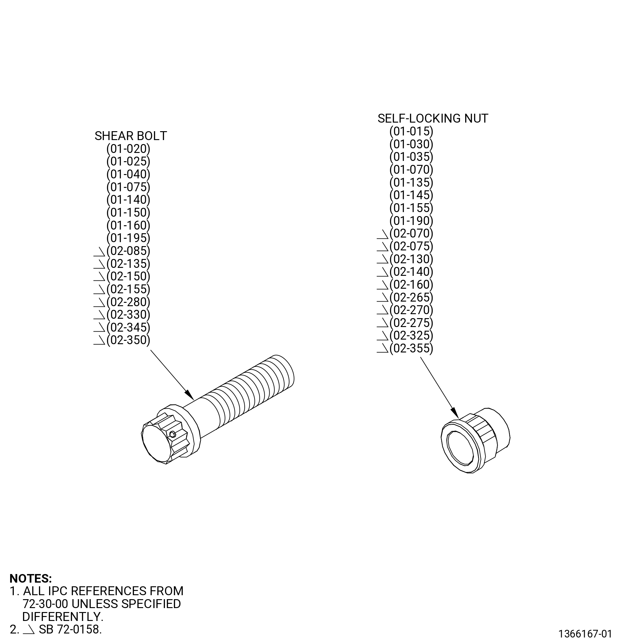
| I. | Do an inspection of all other bolts for. Refer to Figure 801, Figure 802, Figure 802A, and Figure 803. |
| (1) | Damaged threads: |
| Maximum serviceable limit: |
|
| Maximum repairable limit: |
|
| Repair method: |
|
| Subtask 72-30-99-220-036 |
| (2) | Cracks: |
| Maximum serviceable limit: |
|
| Repair method: |
|
| Subtask 72-30-99-220-040 |
| (3) | Axial scratches on the shank: |
| Maximum serviceable limit: |
|
| Repair method: |
|
| Subtask 72-30-99-220-041 |
| J. | Do an inspection of all other nuts for. Refer to Figure 801 and Figure 803. |
| (1) | Cracks: |
| Maximum serviceable limit: |
|
| Repair method: |
|
| Subtask 72-30-99-220-042 |
| (2) | Damage to the threads: |
| Maximum serviceable limit: |
|
| Maximum repairable limit: |
|
| Repair method: |
|
| Subtask 72-30-99-220-043 |
| (3) | Loss of the self-locking quality: |
| Maximum serviceable limit: |
|
| Repair method: |
|
| Subtask 72-30-99-220-048 |
| K. | Do an inspection of the alignment pin for. Refer to Figure 807 and as follows: |
| (1) | Wear on outer diameter (OD): |
| Maximum serviceable limit: |
|
| Repair method: |
|